EP3054706A2 - Binaurales hörsystem und hörgerät mit einer strahlformungseinheit - Google Patents
Binaurales hörsystem und hörgerät mit einer strahlformungseinheit Download PDFInfo
- Publication number
- EP3054706A2 EP3054706A2 EP16154436.6A EP16154436A EP3054706A2 EP 3054706 A2 EP3054706 A2 EP 3054706A2 EP 16154436 A EP16154436 A EP 16154436A EP 3054706 A2 EP3054706 A2 EP 3054706A2
- Authority
- EP
- European Patent Office
- Prior art keywords
- hearing
- binaural
- unit
- devices
- signal
- Prior art date
- Legal status (The legal status is an assumption and is not a legal conclusion. Google has not performed a legal analysis and makes no representation as to the accuracy of the status listed.)
- Withdrawn
Links
Images


Classifications
-
- H—ELECTRICITY
- H04—ELECTRIC COMMUNICATION TECHNIQUE
- H04R—LOUDSPEAKERS, MICROPHONES, GRAMOPHONE PICK-UPS OR LIKE ACOUSTIC ELECTROMECHANICAL TRANSDUCERS; DEAF-AID SETS; PUBLIC ADDRESS SYSTEMS
- H04R25/00—Deaf-aid sets, i.e. electro-acoustic or electro-mechanical hearing aids; Electric tinnitus maskers providing an auditory perception
- H04R25/55—Deaf-aid sets, i.e. electro-acoustic or electro-mechanical hearing aids; Electric tinnitus maskers providing an auditory perception using an external connection, either wireless or wired
- H04R25/552—Binaural
-
- H—ELECTRICITY
- H04—ELECTRIC COMMUNICATION TECHNIQUE
- H04R—LOUDSPEAKERS, MICROPHONES, GRAMOPHONE PICK-UPS OR LIKE ACOUSTIC ELECTROMECHANICAL TRANSDUCERS; DEAF-AID SETS; PUBLIC ADDRESS SYSTEMS
- H04R25/00—Deaf-aid sets, i.e. electro-acoustic or electro-mechanical hearing aids; Electric tinnitus maskers providing an auditory perception
- H04R25/40—Arrangements for obtaining a desired directivity characteristic
- H04R25/407—Circuits for combining signals of a plurality of transducers
-
- H—ELECTRICITY
- H04—ELECTRIC COMMUNICATION TECHNIQUE
- H04R—LOUDSPEAKERS, MICROPHONES, GRAMOPHONE PICK-UPS OR LIKE ACOUSTIC ELECTROMECHANICAL TRANSDUCERS; DEAF-AID SETS; PUBLIC ADDRESS SYSTEMS
- H04R1/00—Details of transducers, loudspeakers or microphones
- H04R1/10—Earpieces; Attachments therefor ; Earphones; Monophonic headphones
- H04R1/1041—Mechanical or electronic switches, or control elements
-
- H—ELECTRICITY
- H04—ELECTRIC COMMUNICATION TECHNIQUE
- H04R—LOUDSPEAKERS, MICROPHONES, GRAMOPHONE PICK-UPS OR LIKE ACOUSTIC ELECTROMECHANICAL TRANSDUCERS; DEAF-AID SETS; PUBLIC ADDRESS SYSTEMS
- H04R1/00—Details of transducers, loudspeakers or microphones
- H04R1/20—Arrangements for obtaining desired frequency or directional characteristics
- H04R1/32—Arrangements for obtaining desired frequency or directional characteristics for obtaining desired directional characteristic only
- H04R1/40—Arrangements for obtaining desired frequency or directional characteristics for obtaining desired directional characteristic only by combining a number of identical transducers
- H04R1/406—Arrangements for obtaining desired frequency or directional characteristics for obtaining desired directional characteristic only by combining a number of identical transducers microphones
-
- H—ELECTRICITY
- H04—ELECTRIC COMMUNICATION TECHNIQUE
- H04R—LOUDSPEAKERS, MICROPHONES, GRAMOPHONE PICK-UPS OR LIKE ACOUSTIC ELECTROMECHANICAL TRANSDUCERS; DEAF-AID SETS; PUBLIC ADDRESS SYSTEMS
- H04R2203/00—Details of circuits for transducers, loudspeakers or microphones covered by H04R3/00 but not provided for in any of its subgroups
- H04R2203/12—Beamforming aspects for stereophonic sound reproduction with loudspeaker arrays
-
- H—ELECTRICITY
- H04—ELECTRIC COMMUNICATION TECHNIQUE
- H04R—LOUDSPEAKERS, MICROPHONES, GRAMOPHONE PICK-UPS OR LIKE ACOUSTIC ELECTROMECHANICAL TRANSDUCERS; DEAF-AID SETS; PUBLIC ADDRESS SYSTEMS
- H04R2225/00—Details of deaf aids covered by H04R25/00, not provided for in any of its subgroups
- H04R2225/39—Aspects relating to automatic logging of sound environment parameters and the performance of the hearing aid during use, e.g. histogram logging, or of user selected programs or settings in the hearing aid, e.g. usage logging
-
- H—ELECTRICITY
- H04—ELECTRIC COMMUNICATION TECHNIQUE
- H04R—LOUDSPEAKERS, MICROPHONES, GRAMOPHONE PICK-UPS OR LIKE ACOUSTIC ELECTROMECHANICAL TRANSDUCERS; DEAF-AID SETS; PUBLIC ADDRESS SYSTEMS
- H04R2225/00—Details of deaf aids covered by H04R25/00, not provided for in any of its subgroups
- H04R2225/43—Signal processing in hearing aids to enhance the speech intelligibility
-
- H—ELECTRICITY
- H04—ELECTRIC COMMUNICATION TECHNIQUE
- H04R—LOUDSPEAKERS, MICROPHONES, GRAMOPHONE PICK-UPS OR LIKE ACOUSTIC ELECTROMECHANICAL TRANSDUCERS; DEAF-AID SETS; PUBLIC ADDRESS SYSTEMS
- H04R25/00—Deaf-aid sets, i.e. electro-acoustic or electro-mechanical hearing aids; Electric tinnitus maskers providing an auditory perception
- H04R25/55—Deaf-aid sets, i.e. electro-acoustic or electro-mechanical hearing aids; Electric tinnitus maskers providing an auditory perception using an external connection, either wireless or wired
- H04R25/558—Remote control, e.g. of amplification, frequency
-
- H—ELECTRICITY
- H04—ELECTRIC COMMUNICATION TECHNIQUE
- H04R—LOUDSPEAKERS, MICROPHONES, GRAMOPHONE PICK-UPS OR LIKE ACOUSTIC ELECTROMECHANICAL TRANSDUCERS; DEAF-AID SETS; PUBLIC ADDRESS SYSTEMS
- H04R3/00—Circuits for transducers, loudspeakers or microphones
- H04R3/005—Circuits for transducers, loudspeakers or microphones for combining the signals of two or more microphones
-
- H—ELECTRICITY
- H04—ELECTRIC COMMUNICATION TECHNIQUE
- H04R—LOUDSPEAKERS, MICROPHONES, GRAMOPHONE PICK-UPS OR LIKE ACOUSTIC ELECTROMECHANICAL TRANSDUCERS; DEAF-AID SETS; PUBLIC ADDRESS SYSTEMS
- H04R5/00—Stereophonic arrangements
- H04R5/033—Headphones for stereophonic communication
Definitions
- the present application relates to hearing devices, in particular to a binaural hearing system comprising first and second hearing devices.
- the disclosure relates specifically to a binaural hearing system comprising first and second hearing devices adapted for being mounted at or in left and right ears of a user, each hearing device comprising a beamformer unit for generating a beamformed signal from first and second electric input signals.
- the application furthermore relates to a method of operating a binaural hearing system.
- Embodiments of the disclosure may e.g. be useful in applications such as binaural hearing aid systems, ear phone or ear protection systems.
- FIG. 1A shows a standard reaction of a (two-microphone) hearing instrument to focus listening in a given direction, i.e. to listen to two persons talking, where both instruments of a binaural hearing system are focused on both talkers (at the same time) meaning they will receive almost the same sound mix at each ear.
- the present application relates to a binaural hearing system comprising left and right hearing devices, each hearing device comprising a beamformer unit.
- An alternative directional mode termed Dual-DIR mode in the present disclosure.
- the Dual-DIR mode is preferably entered in a 'two-persons-talking scenario'.
- Such acoustic situation may e.g. be identified manually, e.g. by a user, e.g. via a user interface, or automatically, e.g. using advanced algorithms and information interchange between the two hearing devices (and/or an auxiliary device) of the binaural hearing system.
- the Dual-DIR mode is entered, wherein the beamformer units of the first and second hearing devices focus their beams to cover only ONE talker each (e.g. respective first and second talkers). This is schematically illustrated in FIG. 1 B
- the respective voices can be forwarded from the hearing device where it has been picked up to the other hearing device of the binaural hearing system (optionally processed to be separated in time, to include directional cues (e.g. by applying e.g. pre-determined) head-related transfer functions (HRTFs).
- HRTFs head-related transfer functions
- performance can also be further enhanced by using psycho-acoustic algorithms to make the voices appear as if the persons were placed farther away from each other than they are in real-life. This method might be more 'listen-friendly' than just providing one talker in each ear.
- An object of the present application is provide an alternative scheme for separating two target sound sources in a mixed sound environment.
- a binaural hearing system :
- a binaural hearing system comprising first and second hearing devices, e.g. hearing aids, adapted for being mounted at or in left and right ears or fully or partially implanted in the head of a user, each hearing device comprising first and second input units providing first and second electric input signals representing first and second sound signals from the environment of the binaural hearing system,
- each of the first and second hearing devices of the binaural hearing system comprises an output unit for generating or receiving and presenting stimuli perceivable to a user as sound.
- the binaural hearing system is configured to present a signal originating from the first sound source via the output unit of the first hearing device, and to present a signal originating from the second sound source via the output unit of the second hearing device.
- the binaural hearing system is adapted to establish a communication link between the first and second hearing devices.
- each of the first and second hearing devices comprises antenna and transceiver circuitry for establishing a wireless communication link between the two hearing devices (e.g. via a third (auxiliary) device).
- the binaural hearing system comprises a user interface allowing a user to control functionality of the binaural hearing system (or to present data, e.g. processed to the user, e.g. graphically).
- the binaural hearing system comprises a user interface allowing a user to control functionality of the beamformer unit.
- the binaural hearing system is configured to allow a selection of a mode of operation, e.g. the 'dual DIR' mode of operation, of the binaural hearing system via the user interface.
- the binaural hearing system is configured to operate in at least two modes, the dual DIR mode and a normal mode of operation (different from the dual DIR mode).
- the binaural hearing system comprises an environment classification unit for classifying the current acoustic environment.
- the binaural hearing system e.g. an auxiliary device
- each of the first and second hearing devices comprises an environment classification unit for classifying the current acoustic environment (around the respective hearing device).
- the binaural hearing system is configured to exchange information about the current acoustic environment between devices of the binaural hearing system, and optionally external devices.
- at least one (preferably both) of the first and second hearing devices comprises antenna and transceiver circuitry for establishing a wireless communication link to an auxiliary device.
- the binaural hearing system comprises a source localization unit for localizing one or more sound sources in the acoustic environment.
- each of the first and second hearing devices comprises a source localization unit for localizing one or more sound sources in the acoustic environment (around the respective hearing device).
- the source localization unit is configured to localize one or more sound sources S s in the acoustic environment relative to the location of the binaural hearing system (or relative to a particular hearing device of the binaural hearing system, e.g. based on first and second electric input signals of a particular hearing device).
- a sound source localization unit is fully or partially implemented in an auxiliary device, e.g. a SmartPhone.
- At least one of the first and second hearing devices is/are configured to receive from an auxiliary device a location information related to a direction to and/or location of the first and/or second target sound source relative to the at least one of the first and second hearing devices.
- the user interface is implemented in the auxiliary device, e.g. a remote control device, a cellular telephone (e.g. a SmartPhone), or other communication device.
- the binaural hearing system comprises the auxiliary device.
- the auxiliary device e.g. a SmartPhone, is configured to run an APP allowing to control the functionality of the binaural hearing system and/or to provide a user interface.
- the first and/or second hearing device(s) comprises an appropriate wireless interface to the auxiliary device (e.g. a SmartPhone), e.g. based on Bluetooth or some other standardized or proprietary scheme.
- At least one of the first and second hearing devices is/are configured to receive system location information from the user interface.
- the first and second hearing devices each comprise a source localization unit for localizing one or more sound sources in the acoustic environment.
- the first and second hearing devices are configured to identify said first and second (different) sound sources (each e.g. comprising speech).
- the first and second hearing devices are configured to transmit location information (e.g. direction or angle information regarding a dominant sound source (e.g. comprising speech)) to the opposite hearing device (e.g. for comparison and possible mode change).
- location information e.g. direction or angle information regarding a dominant sound source (e.g. comprising speech)
- the binaural hearing system e.g. each hearing device
- the first and second hearing devices are configured to enter the dual DIR mode of operation based on said location information from the first and second hearing devices.
- the first and second hearing devices are configured to transmit location information to an auxiliary device (e.g. for display at a user interface).
- an auxiliary device e.g. for display at a user interface
- each hearing device comprises more than two input units, e.g. a third input unit in addition to said first and second input units.
- each of the first and second input units comprises a microphone.
- each hearing device comprises a third input unit configured to receive an electric input signal from another device, e.g. from the other hearing device of the binaural hearing system, or from an auxiliary device.
- each of the first and second input units comprises a time to time-frequency conversion unit for providing the first and second electric input signals in a time-frequency representation.
- each of the input units of the first and second hearing devices comprises a time to time-frequency conversion unit for providing the respective electric input signals in a time-frequency representation.
- the binaural hearing system is configured to provide that a signal originating from the first sound source is transmitted to the second hearing device and/or a signal originating from the second sound source is transmitted to the first hearing device via the communication link.
- a communication link between the first and second hearing devices can be established (e.g. to allow the streaming of sound between the first and second hearing devices)
- the signals originating from the first and second sound sources can be forwarded from the hearing device where it has been picked up to the other hearing device of the binaural hearing system (optionally processed, e.g. to be separated in time).
- the binaural hearing system is configured to present a signal originating from the first sound source, which is transmitted to the second hearing device, to the user via the output unit of the second hearing device. In an embodiment, the binaural hearing system is configured to present a signal originating from the second sound source, which is transmitted to the first hearing device, to the user via the output unit of the first hearing device.
- the binaural hearing system is configured to present a signal originating from the first sound source, which is transmitted to the second hearing device, to the user via the output unit of the second hearing device with a configurable delay. In an embodiment, the binaural hearing system is configured to present a signal originating from the second sound source, which is transmitted to the first hearing device, to the user via the output unit of the first hearing device with a configurable delay. In an embodiment, the delay is configured to avoid overlap in time between the signals originating from the first and second sound sources (when presented to the user).
- the binaural hearing system is configured to include directional cues to a signal originating from the first or second sound source when transmitted to and presented to the user via output units of the second and first hearing devices, respectively.
- the binaural hearing system is adapted to include directional cues in the signals originating from the first and second sound source by applying relevant head-related transfer functions (HRTFs) to the signals (the HRTFs being e.g. pre-determined and stored in a memory of the binaural hearing system, e.g. in each of the first and second hearing devices).
- HRTFs head-related transfer functions
- the binaural hearing system is configured to apply a psycho-acoustic algorithm to a signal originating from the first or second sound source to make the presented signals appear to the user as if the first and second target sound sources were placed farther away from or closer to each other than they actually are.
- the hearing device is adapted to provide a frequency dependent gain and/or a level dependent compression and/or a transposition (with or without frequency compression) of one or frequency ranges to one or more other frequency ranges, e.g. to compensate for a hearing impairment of a user.
- the hearing device comprises a signal processing unit for enhancing the input signals and providing a processed output signal.
- the hearing device comprises an output unit for providing a stimulus perceived by the user as an acoustic signal based on a processed electric signal.
- the output unit comprises a number of electrodes of a cochlear implant or a vibrator of a bone conducting hearing device.
- the output unit comprises an output transducer.
- the output transducer comprises a receiver (loudspeaker) for providing the stimulus as an acoustic signal to the user.
- the output transducer comprises a vibrator for providing the stimulus as mechanical vibration of a skull bone to the user (e.g. in a bone-attached or bone-anchored hearing device).
- the hearing device comprises an antenna and transceiver circuitry for wirelessly receiving a direct electric input signal from another device, e.g. a communication device or another hearing device.
- the hearing device comprises a (possibly standardized) electric interface (e.g. in the form of a connector) for receiving a wired direct electric input signal from another device, e.g. a communication device or another hearing device.
- the direct electric input signal represents or comprises an audio signal and/or a control signal and/or an information signal.
- the hearing device comprises demodulation circuitry for demodulating the received direct electric input to provide the direct electric input signal representing an audio signal and/or a control signal e.g. for setting an operational parameter (e.g.
- the wireless link established by a transmitter and antenna and transceiver circuitry of the hearing device can be of any type.
- the wireless link is a link based on near-field communication, e.g. an inductive link based on an inductive coupling between antenna coils of transmitter and receiver parts.
- the wireless link is based on far-field, electromagnetic radiation.
- the wireless link is based on a standardized or proprietary technology.
- the wireless link is based on Bluetooth technology (e.g. Bluetooth Low-Energy technology).
- the hearing device has a maximum outer dimension of the order of 0.05 m (e.g. a hearing instrument).
- the hearing device is portable device, e.g. a device comprising a local energy source, e.g. a battery, e.g. a rechargeable battery.
- a local energy source e.g. a battery, e.g. a rechargeable battery.
- the hearing device comprises a forward or signal path between an input transducer (microphone system and/or direct electric input (e.g. a wireless receiver)) and an output transducer.
- the signal processing unit is located in the forward path.
- the signal processing unit is adapted to provide a frequency dependent gain according to a user's particular needs.
- the hearing device comprises an analysis path comprising functional components for analyzing the input signal (e.g. determining a level, a modulation, a type of signal, an acoustic feedback estimate, etc.).
- some or all signal processing of the analysis path and/or the signal path is conducted in the frequency domain.
- some or all signal processing of the analysis path and/or the signal path is conducted in the time domain.
- the hearing devices comprise an analogue-to-digital (AD) converter to digitize an analogue input with a predefined sampling rate, e.g. 20 kHz.
- the hearing devices comprise a digital-to-analogue (DA) converter to convert a digital signal to an analogue output signal, e.g. for being presented to a user via an output transducer.
- AD analogue-to-digital
- DA digital-to-analogue
- the hearing device e.g. the microphone unit, and or the transceiver unit comprise(s) a TF-conversion unit for providing a time-frequency representation of an input signal.
- the TF conversion unit comprises a filter bank for filtering a (time varying) input signal and providing a number of (time varying) output signals each comprising a distinct frequency range of the input signal.
- the TF conversion unit comprises a Fourier transformation unit for converting a time variant input signal to a (time variant) signal in the frequency domain.
- the hearing device comprises a level detector (LD) for determining the level of an input signal (e.g. on a band level and/or of the full (wide band) signal).
- the input level of the electric microphone signal picked up from the user's acoustic environment is e.g. a classifier of the environment.
- the level detector is adapted to classify a current acoustic environment of the user according to a number of different (e.g. average) signal levels, e.g. as a HIGH-LEVEL or LOW-LEVEL environment.
- the hearing device comprises a voice detector (VD) for determining whether or not an input signal comprises a voice signal (at a given point in time).
- a voice signal is in the present context taken to include a speech signal from a human being. It may also include other forms of utterances generated by the human speech system (e.g. singing).
- the voice detector unit is adapted to classify a current acoustic environment of the user as a VOICE or NO-VOICE environment. This has the advantage that time segments of the electric microphone signal comprising human utterances (e.g. speech) in the user's environment can be identified, and thus separated from time segments only comprising other sound sources (e.g. artificially generated noise).
- the hearing device comprises an own voice detector for detecting whether a given input sound (e.g. a voice) originates from the voice of the user of the system.
- a given input sound e.g. a voice
- the hearing device comprises an acoustic (and/or mechanical) feedback suppression system.
- the hearing device further comprises other relevant functionality for the application in question, e.g. compression, noise reduction, etc.
- the hearing device comprises a listening device, e.g. a hearing aid, e.g. a hearing instrument, e.g. a hearing instrument adapted for being located at the ear or fully or partially in the ear canal of a user, e.g. a headset, an earphone, an ear protection device or a combination thereof.
- a listening device e.g. a hearing aid, e.g. a hearing instrument, e.g. a hearing instrument adapted for being located at the ear or fully or partially in the ear canal of a user, e.g. a headset, an earphone, an ear protection device or a combination thereof.
- a hearing device :
- an object of the application is achieved by a hearing device, e.g. a hearing aid, adapted for being mounted at or in left and right ears or fully or partially implanted in the head of a user, the hearing device comprising
- the hearing device is or comprises a hearing aid. In an embodiment, the other device is or comprises another hearing aid.
- a binaural hearing system as described above, in the detailed description of embodiments' and in the claims, is moreover provided.
- use is provided in a system comprising one or more hearing instruments, headsets, ear phones, active ear protection systems, etc.
- a method of operating a binaural hearing system comprising first and second hearing devices adapted for being mounted at or in left and right ears or fully or partially implanted in the head of a user, the method comprising
- the method comprises the step of manually (e.g. via a user interface) or automatically providing a direction to and/or a location of the first and/or second target sound sources.
- a data processing system :
- a data processing system comprising a processor and program code means for causing the processor to perform at least some (such as a majority or all) of the steps of the method described above, in the 'detailed description of embodiments' and in the claims is furthermore provided by the present application.
- a 'hearing device' refers to a device, such as e.g. a hearing instrument or an active ear-protection device or other audio processing device, which is adapted to improve, augment and/or protect the hearing capability of a user by receiving acoustic signals from the user's surroundings, generating corresponding audio signals, possibly modifying the audio signals and providing the possibly modified audio signals as audible signals to at least one of the user's ears.
- a 'hearing device' further refers to a device such as an earphone or a headset adapted to receive audio signals electronically, possibly modifying the audio signals and providing the possibly modified audio signals as audible signals to at least one of the user's ears.
- Such audible signals may e.g.
- acoustic signals radiated into the user's outer ears acoustic signals transferred as mechanical vibrations to the user's inner ears through the bone structure of the user's head and/or through parts of the middle ear as well as electric signals transferred directly or indirectly to the cochlear nerve of the user.
- the hearing device may be configured to be worn in any known way, e.g. as a unit arranged behind the ear with a tube leading radiated acoustic signals into the ear canal or with a loudspeaker arranged close to or in the ear canal, as a unit entirely or partly arranged in the pinna and/or in the ear canal, as a unit attached to a fixture implanted into the skull bone, as an entirely or partly implanted unit, etc.
- the hearing device may comprise a single unit or several units communicating electronically with each other.
- a hearing device comprises an input transducer for receiving an acoustic signal from a user's surroundings and providing a corresponding input audio signal and/or a receiver for electronically (i.e. wired or wirelessly) receiving an input audio signal, a signal processing circuit for processing the input audio signal and an output means for providing an audible signal to the user in dependence on the processed audio signal.
- an amplifier may constitute the signal processing circuit.
- the output means may comprise an output transducer, such as e.g. a loudspeaker for providing an airborne acoustic signal or a vibrator for providing a structure-borne or liquid-borne acoustic signal.
- the output means may comprise one or more output electrodes for providing electric signals.
- the vibrator may be adapted to provide a structure-borne acoustic signal transcutaneously or percutaneously to the skull bone.
- the vibrator may be implanted in the middle ear and/or in the inner ear.
- the vibrator may be adapted to provide a structure-borne acoustic signal to a middle-ear bone and/or to the cochlea.
- the vibrator may be adapted to provide a liquid-borne acoustic signal to the cochlear liquid, e.g. through the oval window.
- the output electrodes may be implanted in the cochlea or on the inside of the skull bone and may be adapted to provide the electric signals to the hair cells of the cochlea, to one or more hearing nerves, to the auditory cortex and/or to other parts of the cerebral cortex.
- a 'hearing system' refers to a system comprising one or two hearing devices
- a 'binaural hearing system' refers to a system comprising one or two hearing devices and being adapted to cooperatively provide audible signals to both of the user's ears.
- Listening systems or binaural listening systems may further comprise 'auxiliary devices', which communicate with the hearing devices and affect and/or benefit from the function of the hearing devices.
- Auxiliary devices may be e.g. remote controls, audio gateway devices, mobile phones, public-address systems, car audio systems or music players.
- Hearing devices, listening systems or binaural listening systems may e.g. be used for compensating for a hearing-impaired person's loss of hearing capability, augmenting or protecting a normal-hearing person's hearing capability and/or conveying electronic audio signals to a person.
- the electronic hardware may include microprocessors, microcontrollers, digital signal processors (DSPs), field programmable gate arrays (FPGAs), programmable logic devices (PLDs), gated logic, discrete hardware circuits, and other suitable hardware configured to perform the various functionality described throughout this disclosure.
- Computer program shall be construed broadly to mean instructions, instruction sets, code, code segments, program code, programs, subprograms, software modules, applications, software applications, software packages, routines, subroutines, objects, executables, threads of execution, procedures, functions, etc., whether referred to as software, firmware, middleware, microcode, hardware description language, or otherwise.
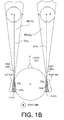
- FIG. 1A and 1B show two different modes of operation of beamfomer units of first and second hearing devices of a binaural hearing system, FIG. 1A illustrating a normal mode of operation, and FIG. 1B illustrating a Dual DIR mode of operation according to the present disclosure.
- the acoustic situation schematically illustrated by FIG. 1A and 1 B is the same, a user (U) listening to a conversation between two persons (A and B ) in front of the user (here shown in a direction of attention, a look direction ( LOOK-DIR ), of the user (U)).
- the user is equipped with left and right hearing devices (L-HD and R-HD) located at the left (Left ear ) and right ears ( Right ear ), respectively, of the user.
- L-HD and R-HD left and right hearing devices located at the left (Left ear ) and right ears ( Right ear ), respectively, of the user.
- the left and right hearing devices each comprises at least two input units for providing first and second electric input signals representing first and second sound signals from the environment of the binaural hearing system, and a beamformer unit for generating a beamformed signal from the first and second electric input signals.
- the first and second input units are implemented by front (FM L , FM R ) and rear (RM L , RM R ) microphones, in the left and right hearing devices, respectively, 'front' and 'rear' being defined relative to the look direction of the user (and assuming that the hearing devices are correctly mounted). located in a front and rear.
- the front ( FM L , FM R ) and rear ( RM L , RM R ) microphones of the left and right hearing devices, respectively, constitute respective microphone systems, which together with respective configurable beamformer units allow each hearing device to maximize the sensitivity of the microphone system (cf. schematic beams BEAM L and BEAM R , respectively) in a specific direction relative to the hearing device in question ( REF-DIR L , REF-DIR R , respectively, e.g. equal to the look direction ( LOOK-DIR ) of the user, assuming that the hearing devices are correctly mounted).
- 1A and 1B is intended to represent a horizontal cross-sectional view perpendicular to the surface on which the two persons A and B and the user U are standing (or otherwise located), as indicated by the symbol denoted VERT-DIR intended to indicate a vertical direction with respect to said surface (e.g. of the earth).
- FIG. 1A schematically shows a typical configuration of the beamformed signals of a binaural hearing system comprising left and right (two-microphone) hearing devices ( L-HD and R-HD) focusing listening on a given target, here aiming to listen to two persons talking.
- L-HD and R-HD left and right hearing devices
- FIG. 1B schematically illustrates the Dual-DIR mode according to the present disclosure.
- the beamformer units of the left and right hearing devices (L-HD and R-HD) each are configured to focus their beams to cover only ONE talker each (e.g. respective first and second talkers; here the left hearing device (L-HD) focuses on person A and the right hearing device (R-HD) focuses on person B).
- the focused beams BEAM L and BEAM R of the left and right hearing devices are defined by directions DIR A and DIR B from the left and right hearing devices to persons A and B respectively.
- the respective 'clean' signals from person A and B are presented to the user (U) as received by the respective hearing device (L-HD and R-HD).
- This has the advantage of (to a certain extent) separate the two sound sources (A and B) compared to the mixture of the two signals picked up by the binaural hearing system of FIG. 1A .
- Other uses of the respective received signals at the left and right hearing devices may advantageously be made, typically involving some sort of processing of the 'clean' received signals (e.g. delay, frequency shaping, and/or addition of directional cues), as outlined in connection with the embodiments described in the following.
- the binaural hearing system is configured to apply a psycho-acoustic algorithm to a signal originating from the first or second sound source to make the presented signals appear to the user as if the first and second target sound sources were placed farther away from or closer to each other than they actually are.
- the focused beams BEAM L and BEAM R of the left and right hearing devices are schematically shown in FIG. 1A and 1B as clearly defined angular sectors (in the presented cross-section).
- the 'beams' will be less clearly defined and not necessarily exhibit a linearly limited cross-section of a cone.
- the beams are illustrated as if they stop at the location of the persons A and B. This need not be the case either.
- the beams may cover a larger area beyond the location of the persons A and B.
- the beams BEAM L and BEAM R of the left and right hearing devices are configured to 'just include' the persons A and B (i.e. to reflect a direction ( DIR A , DIR B ) and distance from the left and right hearing devices to the persons A and B, respectively).
- FIG. 2 shows an embodiment of a binaural hearing system comprising first and second hearing devices according to the present disclosure.
- the first and second hearing devices (also termed left and right hearing devices, and denoted L-HD and R-HD in the drawings) are adapted for being mounted at or in left and right ears or fully or partially implanted in the head of a user.
- Each of the left and right hearing devices further comprises a beamformer unit ( BF ) for generating a beamformed signal RBFS from the multitude of electric input signals ( l 1 , l 2 , ..., l M ).
- the left and right hearing devices further comprises respective control unit ( CONT ) for controlling the beamformer units in its various modes of operation (cf. signal BFC ), including in the specific dual DIR mode of operation aimed at a listening situation comprising first and second target sound sources (cf. FIG. 1 B) .
- the binaural hearing system is configured to provide that - in the dual DIR mode of operation - the contol unit ( CONT ) of the left hearing device (L-HD) is configured to focus the beamformer unit ( BF ) of the left hearing device on the first target sound source (person A in FIG. 1 B) , and the control unit of the right hearing device (R-HD) is configured to focus the beamformer unit ( BF ) of the right hearing device on the second target sound source (person B in FIG. 1B ).
- CONT contol unit
- L-HD the contol unit of the left hearing device
- R-HD is configured to focus the beamformer unit ( BF ) of the right hearing device on the second target sound source (person B in FIG. 1B ).
- each of the left and right hearing devcies comprises a signal processing unit (SPU) for processing the beamformed signal RBFS and provide a processed signal EOUT to an output unit ( OU ) for generating or receiving and presenting stimuli perceivable to a user as sound based thereon (the output stimuli being denoted Output u L and Output u R in the left and right hearing devices, respectively).
- the binaural hearing system is configured to present a signal originating from the first sound source (person A in FIG. 1 B) via the output unit ( OU ) of the left hearing device, and to present a signal originating from the second sound source (person B in FIG. 1 B) via the output unit ( OU ) of the right hearing device.
- a forward path from Sound input to Output is defined by the operational connection of the input units ( IU ), the beamformer unit ( BF ), the signal processing unit (SPU) and the output unit ( OU ) and any functional components located there between.
- the number M of input units is two, such as three or four.
- the binaural hearing system is adapted to establish a communication link between the left and right hearing devices (L-HD, R-HD).
- Each of the left and right hearing devices comprises antenna and transceiver circuitry ( IA-Rx / Tx ) for establishing a wireless communication link ( IA-WLS ) between the two hearing devices (e.g. directly, as indicated, or via a third (auxiliary) device).
- the inter-aural link can e.g. be used to exchange respective audio signals (e.g. the beamformed signals ( RBFS )) between the left and right hearing devices.
- the binaural hearing system is configured to transmit a signal originating from the first sound source (person A in FIG.
- the binaural hearing system may be configured to transmit a signal originating from the second sound source (person B in FIG. 1 B) , picked up by the right hearing device, to the left hearing device via the communication link ( IA-WLS ).
- the transmitted audio signals are received and extracted in the respective transceiver units ( IA-Tx / Rx ) and preferably forwarded to respective signal processing units (SPU), cf. signal TS-C.
- SPU signal processing units
- Control or information signals may likewise be exchanged between the first and second hearing devices via the inter-aural communication link ( IA-WLS ), and forwarded to appropriate functional units, e.g. to the control unit for controlling the beamformer unit ( BF ) (cf. signal IAC ) and/or to the processing units (SPU) for controlling the processing of signals of the forward path (cf. signal TS-C).
- the binaural hearing system may be configured to present a signal originating from the first sound source (person A in FIG. 1 B) , picked up by the left hearing device, and which is transmitted to the second hearing device, to the user via the output unit ( OU ) of the second hearing device.
- the binaural hearing system may be configured to present a signal originating from the second sound source (person B in FIG. 1B ), picked up by the right hearing device, and which is transmitted to the first hearing device, to the user via the output unit ( OU ) of the first hearing device.
- the audio signals received from the opposite hearing device are processed in advance of being presented to the user.
- an audio signal (the 'opposite audio signal') received in a first hearing device from an (opposite) second hearing device is mixed with an audio signal (the 'local audio signal') picked up by the first hearing device itself.
- the processing (e.g. mixing) of audio signals received from the opposite hearing device comprise the application of a configurable delay to the opposite and/or to the local audio signals to avoid or minimize substantial overlap in time of speech content in the respective signals.
- the binaural hearing system is configured to include directional cues to a signal originating from the first or second sound source when transmitted to and presented to the user via output units of the opposite hearing devices (i.e. the second and first hearing devices, respectively).
- the input unit ( IU ) may comprise one or more input transducers, e.g. microphone units (such as M 1 , M 2 in FIG. 3A and 3B ), preferably having an omni-directional gain characteristic, and/or one or more receivers of an audio signal, e.g. a wireless receiver.
- the output unit (OU) may comprise an output transducer, e.g. a loudspeaker (such as SP in FIG. 3A and 3B ) for converting an electric signal to an acoustic signal, and/or a transmitter (e.g. a wireless transmitter) for forwarding the resulting signal to another device for further analysis and/or presentation.
- the output unit ( OU ) may alternatively (or additionally) comprise a vibrator of a bone anchored hearing aid and/or a multi-electrode stimulation arrangement of a cochlear implant type hearing aid for providing a mechanical vibration of bony tissue and electrical stimulation of the cochlear nerve, respectively.
- the input unit IU comprises a microphone array comprising a multitude of microphones (e.g. more than two).
- the beamformer filter ( BF ) is configured for making frequency-dependent directional filtering of the electric input signals ( l 1 , l 2 , ..., l M ).
- the output of the beamformer filter ( BF ) is a resulting beamformed output signal ( RBFS ), e.g. being optimized to comprise a relatively large (target) signal (S) component and a relatively small noise (N) component (e.g. to have a relatively large gain in a direction of the target signal and to comprise a minimum of noise).
- the signal processing unit is configured to apply a level and/or frequency dependent gain to the input signal (here RBFS ), e.g. to adjust the input signal to the impaired hearing ability of the user.
- the beamformer unit comprises a combined beam-former-noise reduction system.
- Such systems may be implemented in many different ways as is customary in the art, e.g. as a Minimum Variance Distortionless Response (MVDR) beam former and a single-channel post-filter (see e.g. EP2701145A1 ).
- MVDR Minimum Variance Distortionless Response
- the hearing devices of FIG. 2 may further comprise other functionality, such as a feedback estimation and/or cancellation system (for reducing or cancelling acoustic or mechanical feedback leaked via an 'external' feedback path from output to input transducer of the hearing device).
- a feedback estimation and/or cancellation system for reducing or cancelling acoustic or mechanical feedback leaked via an 'external' feedback path from output to input transducer of the hearing device.
- the signal processing is performed on digital signals.
- the hearing device comprises appropriate analogue-to-digital (AD) and possibly digital-to-analogue (DA) converters (e.g. forming part of the input and possibly output units (e.g. transducers)).
- AD analogue-to-digital
- DA digital-to-analogue
- the signal processing (or a part thereof) is performed in the analogue domain.
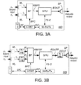
- FIG. 3 A and 3B show two embodiments of a hearing device adapted to form part of a binaural hearing system according to the present disclosure.
- a binaural hearing system can e.g. be provided by two hearing devices as shown in FIG. 3A or FIG. 3B located at or in left and right ears of a user.
- FIG. 3A and 3B both shows a hearing device ( HD ) including the functional elements and operational connections as shown in FIG. 2 (represented by any of the left and right hearing devices ( L-HD, R-HD )) and described above.
- the embodiments of FIG. 3A and 3B additionally comprise a user interface ( UI ) allowing a user to control functionality of the hearing device, e.g. the beamformer unit ( BF ).
- the output unit ( OU ) is in the embodiments of FIG. 3A and 3B implemented as a loudspeaker unit (SP) converting the processed signal EOUT to an Acoustic output signal , u.
- the user interface ( IU ) is configured to allow a user to control functionality (e.g. a mode of operation, e.g. of the beamformer unit) of the binaural hearing system (and/or to present data, e.g. processed data, to the user, e.g. graphically), cf. signal UIC .
- the user interface ( UI ) comprises an activation element on the hearing device ( HD ).
- the binaural hearing system is configured to allow a selection of a mode of operation, e.g. the 'dual DIR' or a 'normal' mode of operation, of the binaural hearing system via the user interface.
- FIG. 3A illustrates an embodiment of a hearing device ( HD ), where signal processing of the forward path (e.g. in the beamformer unit ( BF ) and in the signal processing unit ( SPU )) is performed in the time domain.
- signal processing of the forward path e.g. in the beamformer unit ( BF ) and in the signal processing unit ( SPU )
- FIG. 3B illustrates an embodiment of a hearing device ( HD ), where signal processing of the forward path is performed in the time-frequency domain, e.g. in a number of frequency bands.
- This is implemented by including an analysis filter bank ( A-FB ) in each of the microphone paths (between the microphone units M 1 and M 2 and the beamformer unit ( BF )) and a synthesis filter bank ( S-FB ) between the signal processing unit (SPU) and the loudspeaker unit ( SP ).
- A-FB analysis filter bank
- S-FB synthesis filter bank
- the transceiver unit ( IA-Rx / Tx ) comprises a time to time frequency conversion unit (e.g. an analysis filter bank) to convert a signal received from an opposite hearing device into the time-frequency domain (so that it can be processed, and possibly mixed with the beamformed signal RBFSF of the forward path, in the signal processing unit ( SPU ), cf. signal TS-C ).
- a time to time frequency conversion unit e.g. an analysis filter bank
- FIG. 4A and 4B shows two further embodiments of a hearing device ( HD ) adapted to form part of a binaural hearing system according to the present disclosure, FIG. 4A and 4B illustrating embodiments comprising an environment classification unit (ECLU) for influencing a mode of operation of the hearing device in question.
- a binaural hearing system can e.g. be provided by two hearing devices as shown in FIG. 4A or FIG. 4B located at or in left and right ears of a user.
- FIG. 4A shows an embodiment of a hearing device ( HD ) comprising a forward path comprising first and second microphones ( M 1 , M 2 ), a beamformer unit ( BF ), a signal processing unit (SPU) and a loudspeaker ( SP ) as in FIG. 3A . It further comprises a control unit (CONT) and a transceiver unit (IA-Rx / Tx ) for establishing a wireless link to another hearing device as also shown in FIG. 3A .
- the embodiment of FIG. 4A comprises an environment classification unit (ECLU) for influencing a mode of operation of the hearing device.
- ECLU environment classification unit
- the environment classification unit (ECLU) is operationally connected to the first and second microphones ( M 1 , M 2 ) (receives electric input signals ( l 1 , l 2 )) and provides mode control signal EC indicative of a type of acoustic environment of the hearing device in question.
- the mode control signal EC is fed to the control unit ( CONT ) and used to influence the mode of operation of the beamformer unit ( BF ), e.g. to identify a dual DIR mode, and configured the bemformer unit to focus on a specific one of the target signals (as illustrated in FIG. 1 B) .
- FIG. 4B shows an embodiment of a hearing device ( HD ) as illustrated in FIG. 4A but additionally comprising a user interface ( UI ).
- the user interface ( UI ) is adapted to allow a user to influence the mode of operation of the hearing device, e.g. in combination with the environment classification unit (ECLU).
- a binaural hearing system comprising left and right hearing devices, each as shown in FIG. 4B , is configured to provide that user inputs via the user interface regarding a mode of operation of the beamformer unit ( BF ) override possible indications from the environment classification unit (ECLU).
- the binaural hearing system e.g.
- one or both of the the left and right hearing devices comprises a source localization unit for localizing one or more sound sources in the acoustic environment.
- An output from such localization unit is preferably used to influence a mode of operation of the binaural hearing system (e.g. the beamformer unit), e.g. whether or not a dual DIR mode can preferably be entered.
- information about the current acoustic environment from the environment classification unit (ECLU) and/or a localization unit are presented to a user via the user interface ( UI ), and may be used by the user to identify an appropriate mode of operation, which may be imposed on the system via the user interface.
- the user interface comprises a graphical interface, e.g. a (possibly touch sensitive) display.
- a single user interface for the binaural hearing system e.g. embodied in a separate auxiliary device, e.g. a remote control, e.g. implemented as an APP of a communication device, e.g. a SmartPhone, is provided.
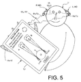
- An embodiment of such a system is illustrated in FIG. 5 .
- FIG. 5 shows an embodiment of a binaural hearing system comprising first e.g. (left) and second hearing (e.g. right) devices (L-HD, R-HD) and an auxiliary device (AD) in communication with the hearing devices.
- the auxiliary device (AD) comprises a user interface ( UI ) for influencing a mode of operation of the binaural hearing system, e.g. each of the left and right hearing devices (L-HD, R-HD), in particular the beamformer units (BF) of the hearing devices.
- UI user interface
- At least one of the left and right hearing devices, preferably both, of the binaural hearing system is configured to receive from the auxiliary device (AD) a location information related to a direction to and/or location of the first and/or second target sound source relative to the left and/or right hearing devices (L-HD, R-HD), cf. e.g. FIG. 1B .
- AD auxiliary device
- L-HD, R-HD left and/or right hearing devices
- the left and right hearing assistance devices are e.g. implemented as described in connection with FIG. 2-4 .
- the binaural hearing assistance system comprises an auxiliary device (AD) in the form of or comprising a cellphone, e.g. a SmartPhone.
- the left and right hearing assistance devices (L-HD, R-HD) and the auxiliary device (AD) each comprise relevant antenna and transceiver circuitry ( Rx / Tx ) for establishing wireless communication links between the hearing assistance devices (link IA-WLS) as well as between at least one of or each of the hearing assistance devices and the auxiliary device (link WL-RF).
- the interaural link IA-WLS is based on near-field communication (e.g. on inductive coupling), but may alternatively be based on radiated fields (e.g. according to the Bluetooth standard, and/or be based on audio transmission utilizing the Bluetooth Low Energy standard).
- the link WL-RF between the auxiliary device and the hearing assistance devices is based on radiated fields (e.g. according to the Bluetooth standard, and/or based on audio transmission utilizing the Bluetooth Low Energy standard), but may alternatively be based on near-field communication (e.g. on inductive coupling).
- the bandwidth of the links ( IA-WLS , WL-RF) is preferably adapted to allow sound source signals (or at least parts thereof, e.g.
- processing of the system e.g. sound source localization
- the function of a remote control is fully or partially implemented in the auxiliary device AD (e.g. a SmartPhone).
- the user interface UI is implemented by the SmartPhone possibly running an APP allowing to control the functionality of the audio processing device via the SmartPhone, e.g. utilizing a display of the SmartPhone to implement a graphical interface (e.g. combined with text entry options).
- a current location of the two target sound sources relative to the user ( U ) can be defined via the user interface ( UI ) of the SmartPhone (which is convenient for viewing and interaction via a touch sensitive display, when the Smartphone is held in a hand (Hand) of the user ( U )).
- the current sound sources A , B (cf. FIG. 1B ) displayed by the user interface may e.g. be located relative to the user by dragging the source symbols (head) to its approximate location.
- the target sound sources are located as in FIG. 1B .
- the binaural hearing assistance system (including the auxiliary device) is configured to determine and transmit localization parameters LP A LP B corresponding to the location of the two target sound sources, as proposed by the user via the user interface, to the left and right hearing assistance devices, respectively, of the binaural hearing assistance system. Additionally, the user is allowed to manipulate the sound field by placing one or more sound sources at another position than its/their physical (or otherwise proposed) location to thereby influence the received signals.
- IA-WLS inductive communication links
- IA-WLS inductive communication links
- EP 1 107 472 A2 EP 1 777 644 A1
- US 2005/0110700 A1 US2011222621A1
- WO 2005/055654 and WO 2005/053179 describe various aspects of a hearing aid comprising an induction coil for inductive communication with other units.
- a protocol for use in an inductive communication link is e.g. described in US 2005/0255843 A1 .
- the RF-communication link ( WL-RF ) is based on classic Bluetooth as specified by the Bluetooth Special Interest Group (SIG) (cf. e.g. https://www.bluetooth.org).
- the (second) RF-communication link is based other standard or proprietary protocols (e.g. a modified version of Bluetooth, e.g. Bluetooth Low Energy modified to comprise an audio layer).
- connection or “coupled” as used herein may include wirelessly connected or coupled.
- the term “and/or” includes any and all combinations of one or more of the associated listed items. The steps of any disclosed method is not limited to the exact order stated herein, unless expressly stated otherwise.
Landscapes
- Engineering & Computer Science (AREA)
- Health & Medical Sciences (AREA)
- General Health & Medical Sciences (AREA)
- Neurosurgery (AREA)
- Otolaryngology (AREA)
- Physics & Mathematics (AREA)
- Acoustics & Sound (AREA)
- Signal Processing (AREA)
- Computer Networks & Wireless Communication (AREA)
- Stereophonic System (AREA)
- Circuit For Audible Band Transducer (AREA)
Priority Applications (1)
| Application Number | Priority Date | Filing Date | Title |
|---|---|---|---|
| EP16154436.6A EP3054706A3 (de) | 2015-02-09 | 2016-02-05 | Binaurales hörsystem und hörgerät mit einer strahlformungseinheit |
Applications Claiming Priority (2)
| Application Number | Priority Date | Filing Date | Title |
|---|---|---|---|
| EP15154289 | 2015-02-09 | ||
| EP16154436.6A EP3054706A3 (de) | 2015-02-09 | 2016-02-05 | Binaurales hörsystem und hörgerät mit einer strahlformungseinheit |
Publications (2)
| Publication Number | Publication Date |
|---|---|
| EP3054706A2 true EP3054706A2 (de) | 2016-08-10 |
| EP3054706A3 EP3054706A3 (de) | 2016-12-07 |
Family
ID=52589227
Family Applications (1)
| Application Number | Title | Priority Date | Filing Date |
|---|---|---|---|
| EP16154436.6A Withdrawn EP3054706A3 (de) | 2015-02-09 | 2016-02-05 | Binaurales hörsystem und hörgerät mit einer strahlformungseinheit |
Country Status (3)
| Country | Link |
|---|---|
| US (1) | US9986346B2 (de) |
| EP (1) | EP3054706A3 (de) |
| CN (1) | CN105872924A (de) |
Cited By (5)
| Publication number | Priority date | Publication date | Assignee | Title |
|---|---|---|---|---|
| FR3052622A1 (fr) * | 2016-06-13 | 2017-12-15 | Elno | Casque acoustique |
| CN111050244A (zh) * | 2019-12-11 | 2020-04-21 | 佳禾智能科技股份有限公司 | 耳机的环境音监听方法、电子设备、计算机可读存储介质 |
| CN113347532A (zh) * | 2020-02-18 | 2021-09-03 | 宏碁股份有限公司 | 指定对象的声源的调控方法及应用其的音源处理装置 |
| EP3890357A1 (de) * | 2020-04-02 | 2021-10-06 | Sivantos Pte. Ltd. | Verfahren zum betrieb eines hörsystems sowie hörsystem |
| US11412332B2 (en) | 2020-10-30 | 2022-08-09 | Sonova Ag | Systems and methods for data exchange between binaural hearing devices |
Families Citing this family (12)
| Publication number | Priority date | Publication date | Assignee | Title |
|---|---|---|---|---|
| DE102015210652B4 (de) * | 2015-06-10 | 2019-08-08 | Sivantos Pte. Ltd. | Verfahren zur Verbesserung eines Aufnahmesignals in einem Hörsystem |
| US11086593B2 (en) * | 2016-08-26 | 2021-08-10 | Bragi GmbH | Voice assistant for wireless earpieces |
| GB201615538D0 (en) | 2016-09-13 | 2016-10-26 | Nokia Technologies Oy | A method , apparatus and computer program for processing audio signals |
| DK3306956T3 (da) * | 2016-10-05 | 2019-10-28 | Oticon As | En binaural stråleformerfiltreringsenhed, et høresystem og en høreanordning |
| DK179577B1 (en) * | 2016-10-10 | 2019-02-20 | Widex A/S | Binaural hearing aid system and a method of operating a binaural hearing aid system |
| US11253193B2 (en) * | 2016-11-08 | 2022-02-22 | Cochlear Limited | Utilization of vocal acoustic biomarkers for assistive listening device utilization |
| US10182299B1 (en) * | 2017-12-05 | 2019-01-15 | Gn Hearing A/S | Hearing device and method with flexible control of beamforming |
| US10425745B1 (en) | 2018-05-17 | 2019-09-24 | Starkey Laboratories, Inc. | Adaptive binaural beamforming with preservation of spatial cues in hearing assistance devices |
| US11089402B2 (en) * | 2018-10-19 | 2021-08-10 | Bose Corporation | Conversation assistance audio device control |
| US10795638B2 (en) | 2018-10-19 | 2020-10-06 | Bose Corporation | Conversation assistance audio device personalization |
| US11134350B2 (en) * | 2020-01-10 | 2021-09-28 | Sonova Ag | Dual wireless audio streams transmission allowing for spatial diversity or own voice pickup (OVPU) |
| US20230130930A1 (en) * | 2020-03-13 | 2023-04-27 | Hewlett-Packard Development Company, L.P. | Disabling spatial audio processing |
Citations (6)
| Publication number | Priority date | Publication date | Assignee | Title |
|---|---|---|---|---|
| EP1107472A2 (de) | 1999-12-02 | 2001-06-13 | Sony Corporation | Digitale Datenübertragungsvorrichtung unter Verwendung induktiver Kopplung |
| US20050110700A1 (en) | 2003-11-25 | 2005-05-26 | Starkey Laboratories, Inc. | Enhanced magnetic field communication system |
| WO2005055654A1 (en) | 2003-11-26 | 2005-06-16 | Starkey Laboratories, Inc. | Transmit-receive switching in wireless hearing aids |
| US20050255843A1 (en) | 2004-04-08 | 2005-11-17 | Hilpisch Robert E | Wireless communication protocol |
| EP1777644A1 (de) | 2005-10-20 | 2007-04-25 | Oticon A/S | System und Verfahren zur Antennenansteuerung |
| US20110222621A1 (en) | 2010-03-10 | 2011-09-15 | Oticon A/S | Wireless communication system with a modulation bandwidth comparable to or exceeding the bandwidth of the transmitter and/or receiver antennas |
Family Cites Families (10)
| Publication number | Priority date | Publication date | Assignee | Title |
|---|---|---|---|---|
| US6011851A (en) * | 1997-06-23 | 2000-01-04 | Cisco Technology, Inc. | Spatial audio processing method and apparatus for context switching between telephony applications |
| AU2008362920B2 (en) * | 2008-10-14 | 2013-09-19 | Widex A/S | Method of rendering binaural stereo in a hearing aid system and a hearing aid system |
| US20110096915A1 (en) * | 2009-10-23 | 2011-04-28 | Broadcom Corporation | Audio spatialization for conference calls with multiple and moving talkers |
| US9025782B2 (en) * | 2010-07-26 | 2015-05-05 | Qualcomm Incorporated | Systems, methods, apparatus, and computer-readable media for multi-microphone location-selective processing |
| US9031256B2 (en) * | 2010-10-25 | 2015-05-12 | Qualcomm Incorporated | Systems, methods, apparatus, and computer-readable media for orientation-sensitive recording control |
| DK2563045T3 (da) * | 2011-08-23 | 2014-10-27 | Oticon As | Fremgangsmåde og et binauralt lyttesystem for at maksimere en bedre øreeffekt |
| EP2680616A1 (de) * | 2012-06-25 | 2014-01-01 | LG Electronics Inc. | Mobiles Endgerät und Audiozoomverfahren dafür |
| DK3190587T3 (en) | 2012-08-24 | 2019-01-21 | Oticon As | Noise estimation for noise reduction and echo suppression in personal communication |
| KR102127640B1 (ko) * | 2013-03-28 | 2020-06-30 | 삼성전자주식회사 | 휴대 단말 및 보청기와 휴대 단말에서 음원의 위치를 제공하는 방법 |
| US10181328B2 (en) * | 2014-10-21 | 2019-01-15 | Oticon A/S | Hearing system |
-
2016
- 2016-02-05 EP EP16154436.6A patent/EP3054706A3/de not_active Withdrawn
- 2016-02-08 US US15/017,942 patent/US9986346B2/en not_active Expired - Fee Related
- 2016-02-14 CN CN201610085005.8A patent/CN105872924A/zh active Pending
Patent Citations (7)
| Publication number | Priority date | Publication date | Assignee | Title |
|---|---|---|---|---|
| EP1107472A2 (de) | 1999-12-02 | 2001-06-13 | Sony Corporation | Digitale Datenübertragungsvorrichtung unter Verwendung induktiver Kopplung |
| US20050110700A1 (en) | 2003-11-25 | 2005-05-26 | Starkey Laboratories, Inc. | Enhanced magnetic field communication system |
| WO2005053179A1 (en) | 2003-11-25 | 2005-06-09 | Starkey Laboratories, Inc. | Enhanced magnetic field communication system |
| WO2005055654A1 (en) | 2003-11-26 | 2005-06-16 | Starkey Laboratories, Inc. | Transmit-receive switching in wireless hearing aids |
| US20050255843A1 (en) | 2004-04-08 | 2005-11-17 | Hilpisch Robert E | Wireless communication protocol |
| EP1777644A1 (de) | 2005-10-20 | 2007-04-25 | Oticon A/S | System und Verfahren zur Antennenansteuerung |
| US20110222621A1 (en) | 2010-03-10 | 2011-09-15 | Oticon A/S | Wireless communication system with a modulation bandwidth comparable to or exceeding the bandwidth of the transmitter and/or receiver antennas |
Cited By (9)
| Publication number | Priority date | Publication date | Assignee | Title |
|---|---|---|---|---|
| FR3052622A1 (fr) * | 2016-06-13 | 2017-12-15 | Elno | Casque acoustique |
| CN111050244A (zh) * | 2019-12-11 | 2020-04-21 | 佳禾智能科技股份有限公司 | 耳机的环境音监听方法、电子设备、计算机可读存储介质 |
| CN113347532A (zh) * | 2020-02-18 | 2021-09-03 | 宏碁股份有限公司 | 指定对象的声源的调控方法及应用其的音源处理装置 |
| CN113347532B (zh) * | 2020-02-18 | 2022-08-30 | 宏碁股份有限公司 | 指定对象的声源的调控方法及应用其的音源处理装置 |
| EP3890357A1 (de) * | 2020-04-02 | 2021-10-06 | Sivantos Pte. Ltd. | Verfahren zum betrieb eines hörsystems sowie hörsystem |
| CN113498006A (zh) * | 2020-04-02 | 2021-10-12 | 西万拓私人有限公司 | 用于运行听力系统的方法和听力系统 |
| US11418898B2 (en) | 2020-04-02 | 2022-08-16 | Sivantos Pte. Ltd. | Method for operating a hearing system and hearing system |
| CN113498006B (zh) * | 2020-04-02 | 2023-08-15 | 西万拓私人有限公司 | 用于运行听力系统的方法和听力系统 |
| US11412332B2 (en) | 2020-10-30 | 2022-08-09 | Sonova Ag | Systems and methods for data exchange between binaural hearing devices |
Also Published As
| Publication number | Publication date |
|---|---|
| EP3054706A3 (de) | 2016-12-07 |
| CN105872924A (zh) | 2016-08-17 |
| US9986346B2 (en) | 2018-05-29 |
| US20160234609A1 (en) | 2016-08-11 |
Similar Documents
| Publication | Publication Date | Title |
|---|---|---|
| US9986346B2 (en) | Binaural hearing system and a hearing device comprising a beamformer unit | |
| EP3101919B1 (de) | Peer-to-peer-hörsystem | |
| US10129663B2 (en) | Partner microphone unit and a hearing system comprising a partner microphone unit | |
| EP3328097B1 (de) | Hörgerät mit einem eigenstimmendetektor | |
| EP3051844B1 (de) | Binaurales Hörsystem | |
| US9860656B2 (en) | Hearing system comprising a separate microphone unit for picking up a users own voice | |
| EP3499915B1 (de) | Hörgerät und binaurales hörsystem mit einem binauralen rauschunterdrückungssystem | |
| EP3373603B1 (de) | Hörgerät mit einem drahtlosen empfänger von schall | |
| EP2869599B1 (de) | Binaurales Hörgerätesystem mit einer Datenbank von kopfbezogenen Übertragungsfunktionen | |
| EP2928214A1 (de) | Binaurales hörgerätesystem mit binauraler rauschunterdrückung | |
| EP3185589A1 (de) | Hörgerät mit mikrofonsteuerungssystem | |
| US20200107137A1 (en) | Hearing device and a hearing system comprising a multitude of adaptive two channel beamformers | |
| EP3713253A1 (de) | Hörgerät mit einem zur platzierung am oder im gehörgang eines benutzers angepassten mikrofon | |
| US20190281395A1 (en) | Binaural level and/or gain estimator and a hearing system comprising a binaural level and/or gain estimator | |
| US20220256296A1 (en) | Binaural hearing system comprising frequency transition | |
| US10085099B2 (en) | Hearing aid system, a hearing aid device and a method of operating a hearing aid system |
Legal Events
| Date | Code | Title | Description |
|---|---|---|---|
| PUAI | Public reference made under article 153(3) epc to a published international application that has entered the european phase |
Free format text: ORIGINAL CODE: 0009012 |
|
| AK | Designated contracting states |
Kind code of ref document: A2 Designated state(s): AL AT BE BG CH CY CZ DE DK EE ES FI FR GB GR HR HU IE IS IT LI LT LU LV MC MK MT NL NO PL PT RO RS SE SI SK SM TR |
|
| AX | Request for extension of the european patent |
Extension state: BA ME |
|
| PUAL | Search report despatched |
Free format text: ORIGINAL CODE: 0009013 |
|
| AK | Designated contracting states |
Kind code of ref document: A3 Designated state(s): AL AT BE BG CH CY CZ DE DK EE ES FI FR GB GR HR HU IE IS IT LI LT LU LV MC MK MT NL NO PL PT RO RS SE SI SK SM TR |
|
| AX | Request for extension of the european patent |
Extension state: BA ME |
|
| RIC1 | Information provided on ipc code assigned before grant |
Ipc: H04R 1/40 20060101ALN20161101BHEP Ipc: H04R 3/00 20060101ALN20161101BHEP Ipc: H04R 25/00 20060101AFI20161101BHEP Ipc: H04R 5/033 20060101ALN20161101BHEP Ipc: H04R 1/10 20060101ALN20161101BHEP |
|
| 17P | Request for examination filed |
Effective date: 20170607 |
|
| RBV | Designated contracting states (corrected) |
Designated state(s): AL AT BE BG CH CY CZ DE DK EE ES FI FR GB GR HR HU IE IS IT LI LT LU LV MC MK MT NL NO PL PT RO RS SE SI SK SM TR |
|
| 17Q | First examination report despatched |
Effective date: 20200422 |
|
| STAA | Information on the status of an ep patent application or granted ep patent |
Free format text: STATUS: THE APPLICATION IS DEEMED TO BE WITHDRAWN |
|
| 18D | Application deemed to be withdrawn |
Effective date: 20200903 |