EP3373603B1 - Hörgerät mit einem drahtlosen empfänger von schall - Google Patents
Hörgerät mit einem drahtlosen empfänger von schall Download PDFInfo
- Publication number
- EP3373603B1 EP3373603B1 EP18160039.6A EP18160039A EP3373603B1 EP 3373603 B1 EP3373603 B1 EP 3373603B1 EP 18160039 A EP18160039 A EP 18160039A EP 3373603 B1 EP3373603 B1 EP 3373603B1
- Authority
- EP
- European Patent Office
- Prior art keywords
- signal
- hearing device
- hearing
- audio signal
- sound
- Prior art date
- Legal status (The legal status is an assumption and is not a legal conclusion. Google has not performed a legal analysis and makes no representation as to the accuracy of the status listed.)
- Active
Links
- 230000005236 sound signal Effects 0.000 claims description 134
- 238000001914 filtration Methods 0.000 claims description 52
- 230000003044 adaptive effect Effects 0.000 claims description 33
- 238000012545 processing Methods 0.000 claims description 32
- 238000000034 method Methods 0.000 claims description 30
- 238000004891 communication Methods 0.000 claims description 18
- 230000000644 propagated effect Effects 0.000 claims description 16
- 230000002238 attenuated effect Effects 0.000 claims description 10
- 239000000203 mixture Substances 0.000 claims description 10
- 238000004590 computer program Methods 0.000 claims description 8
- 230000004886 head movement Effects 0.000 claims description 8
- 230000006870 function Effects 0.000 description 16
- 210000003128 head Anatomy 0.000 description 14
- 230000000875 corresponding effect Effects 0.000 description 11
- 230000008901 benefit Effects 0.000 description 9
- 230000001419 dependent effect Effects 0.000 description 9
- 238000004422 calculation algorithm Methods 0.000 description 8
- 238000012546 transfer Methods 0.000 description 8
- 210000000613 ear canal Anatomy 0.000 description 7
- 230000008569 process Effects 0.000 description 7
- 230000004044 response Effects 0.000 description 7
- 238000004458 analytical method Methods 0.000 description 6
- 230000005540 biological transmission Effects 0.000 description 6
- 230000006835 compression Effects 0.000 description 6
- 238000007906 compression Methods 0.000 description 6
- 230000003321 amplification Effects 0.000 description 5
- 210000005069 ears Anatomy 0.000 description 5
- 208000016354 hearing loss disease Diseases 0.000 description 5
- 239000011159 matrix material Substances 0.000 description 5
- 238000003199 nucleic acid amplification method Methods 0.000 description 5
- 238000006243 chemical reaction Methods 0.000 description 4
- 210000003625 skull Anatomy 0.000 description 4
- 230000017105 transposition Effects 0.000 description 4
- 230000001413 cellular effect Effects 0.000 description 3
- 210000003477 cochlea Anatomy 0.000 description 3
- 230000001276 controlling effect Effects 0.000 description 3
- 210000000959 ear middle Anatomy 0.000 description 3
- 230000000694 effects Effects 0.000 description 3
- 238000005516 engineering process Methods 0.000 description 3
- 230000001939 inductive effect Effects 0.000 description 3
- 230000009467 reduction Effects 0.000 description 3
- 208000032041 Hearing impaired Diseases 0.000 description 2
- 238000003491 array Methods 0.000 description 2
- 230000000903 blocking effect Effects 0.000 description 2
- 210000000988 bone and bone Anatomy 0.000 description 2
- 210000000860 cochlear nerve Anatomy 0.000 description 2
- 238000001514 detection method Methods 0.000 description 2
- 238000010586 diagram Methods 0.000 description 2
- 210000003027 ear inner Anatomy 0.000 description 2
- 230000002708 enhancing effect Effects 0.000 description 2
- 230000014509 gene expression Effects 0.000 description 2
- 239000007943 implant Substances 0.000 description 2
- 230000004807 localization Effects 0.000 description 2
- 230000003287 optical effect Effects 0.000 description 2
- 238000005070 sampling Methods 0.000 description 2
- 239000007787 solid Substances 0.000 description 2
- 210000003926 auditory cortex Anatomy 0.000 description 1
- 230000003190 augmentative effect Effects 0.000 description 1
- 230000015572 biosynthetic process Effects 0.000 description 1
- 210000000133 brain stem Anatomy 0.000 description 1
- 238000004364 calculation method Methods 0.000 description 1
- 210000003710 cerebral cortex Anatomy 0.000 description 1
- 230000001149 cognitive effect Effects 0.000 description 1
- 230000002596 correlated effect Effects 0.000 description 1
- 230000008878 coupling Effects 0.000 description 1
- 238000010168 coupling process Methods 0.000 description 1
- 238000005859 coupling reaction Methods 0.000 description 1
- 230000001934 delay Effects 0.000 description 1
- 238000013461 design Methods 0.000 description 1
- 210000000883 ear external Anatomy 0.000 description 1
- 230000005670 electromagnetic radiation Effects 0.000 description 1
- 210000002768 hair cell Anatomy 0.000 description 1
- 230000001976 improved effect Effects 0.000 description 1
- 230000003993 interaction Effects 0.000 description 1
- 239000007788 liquid Substances 0.000 description 1
- 210000001259 mesencephalon Anatomy 0.000 description 1
- 238000012986 modification Methods 0.000 description 1
- 230000004048 modification Effects 0.000 description 1
- 238000012544 monitoring process Methods 0.000 description 1
- 210000005036 nerve Anatomy 0.000 description 1
- 230000010363 phase shift Effects 0.000 description 1
- 230000035807 sensation Effects 0.000 description 1
- 230000004936 stimulating effect Effects 0.000 description 1
- 239000000758 substrate Substances 0.000 description 1
- 230000001629 suppression Effects 0.000 description 1
- 238000003786 synthesis reaction Methods 0.000 description 1
- 230000009466 transformation Effects 0.000 description 1
Images


Classifications
-
- H—ELECTRICITY
- H04—ELECTRIC COMMUNICATION TECHNIQUE
- H04R—LOUDSPEAKERS, MICROPHONES, GRAMOPHONE PICK-UPS OR LIKE ACOUSTIC ELECTROMECHANICAL TRANSDUCERS; DEAF-AID SETS; PUBLIC ADDRESS SYSTEMS
- H04R25/00—Deaf-aid sets, i.e. electro-acoustic or electro-mechanical hearing aids; Electric tinnitus maskers providing an auditory perception
- H04R25/40—Arrangements for obtaining a desired directivity characteristic
- H04R25/407—Circuits for combining signals of a plurality of transducers
-
- H—ELECTRICITY
- H04—ELECTRIC COMMUNICATION TECHNIQUE
- H04R—LOUDSPEAKERS, MICROPHONES, GRAMOPHONE PICK-UPS OR LIKE ACOUSTIC ELECTROMECHANICAL TRANSDUCERS; DEAF-AID SETS; PUBLIC ADDRESS SYSTEMS
- H04R25/00—Deaf-aid sets, i.e. electro-acoustic or electro-mechanical hearing aids; Electric tinnitus maskers providing an auditory perception
- H04R25/40—Arrangements for obtaining a desired directivity characteristic
- H04R25/405—Arrangements for obtaining a desired directivity characteristic by combining a plurality of transducers
-
- H—ELECTRICITY
- H04—ELECTRIC COMMUNICATION TECHNIQUE
- H04R—LOUDSPEAKERS, MICROPHONES, GRAMOPHONE PICK-UPS OR LIKE ACOUSTIC ELECTROMECHANICAL TRANSDUCERS; DEAF-AID SETS; PUBLIC ADDRESS SYSTEMS
- H04R25/00—Deaf-aid sets, i.e. electro-acoustic or electro-mechanical hearing aids; Electric tinnitus maskers providing an auditory perception
- H04R25/43—Electronic input selection or mixing based on input signal analysis, e.g. mixing or selection between microphone and telecoil or between microphones with different directivity characteristics
-
- H—ELECTRICITY
- H04—ELECTRIC COMMUNICATION TECHNIQUE
- H04R—LOUDSPEAKERS, MICROPHONES, GRAMOPHONE PICK-UPS OR LIKE ACOUSTIC ELECTROMECHANICAL TRANSDUCERS; DEAF-AID SETS; PUBLIC ADDRESS SYSTEMS
- H04R25/00—Deaf-aid sets, i.e. electro-acoustic or electro-mechanical hearing aids; Electric tinnitus maskers providing an auditory perception
- H04R25/50—Customised settings for obtaining desired overall acoustical characteristics
- H04R25/505—Customised settings for obtaining desired overall acoustical characteristics using digital signal processing
-
- H—ELECTRICITY
- H04—ELECTRIC COMMUNICATION TECHNIQUE
- H04R—LOUDSPEAKERS, MICROPHONES, GRAMOPHONE PICK-UPS OR LIKE ACOUSTIC ELECTROMECHANICAL TRANSDUCERS; DEAF-AID SETS; PUBLIC ADDRESS SYSTEMS
- H04R25/00—Deaf-aid sets, i.e. electro-acoustic or electro-mechanical hearing aids; Electric tinnitus maskers providing an auditory perception
- H04R25/55—Deaf-aid sets, i.e. electro-acoustic or electro-mechanical hearing aids; Electric tinnitus maskers providing an auditory perception using an external connection, either wireless or wired
- H04R25/554—Deaf-aid sets, i.e. electro-acoustic or electro-mechanical hearing aids; Electric tinnitus maskers providing an auditory perception using an external connection, either wireless or wired using a wireless connection, e.g. between microphone and amplifier or using Tcoils
-
- H—ELECTRICITY
- H04—ELECTRIC COMMUNICATION TECHNIQUE
- H04R—LOUDSPEAKERS, MICROPHONES, GRAMOPHONE PICK-UPS OR LIKE ACOUSTIC ELECTROMECHANICAL TRANSDUCERS; DEAF-AID SETS; PUBLIC ADDRESS SYSTEMS
- H04R2225/00—Details of deaf aids covered by H04R25/00, not provided for in any of its subgroups
- H04R2225/55—Communication between hearing aids and external devices via a network for data exchange
-
- H—ELECTRICITY
- H04—ELECTRIC COMMUNICATION TECHNIQUE
- H04R—LOUDSPEAKERS, MICROPHONES, GRAMOPHONE PICK-UPS OR LIKE ACOUSTIC ELECTROMECHANICAL TRANSDUCERS; DEAF-AID SETS; PUBLIC ADDRESS SYSTEMS
- H04R2430/00—Signal processing covered by H04R, not provided for in its groups
- H04R2430/20—Processing of the output signals of the acoustic transducers of an array for obtaining a desired directivity characteristic
- H04R2430/25—Array processing for suppression of unwanted side-lobes in directivity characteristics, e.g. a blocking matrix
Definitions
- the present disclosure relates to hearing devices, e.g. hearing aids, and in particular to parallel reception in the hearing device of an audio signal from an audio source, e.g. a TV, via a wireless link and via an acoustic propagation channel, respectively.
- an audio source e.g. a TV
- EP3101919A1 deals with a hearing system comprising first and second hearing aids worn by first and second persons adapted to exchange audio data between them.
- Each of the hearing aids comprises a beamformer unit for spatially filtering electric input signals and a control unit for controlling the beamformer unit and antenna and transceiver circuitry to configure the beam-former unit to retrieve an own voice signal of the person wearing the hearing aid from the electric input signals, and to transmit the own voice signal to the other hearing aid via the antenna and transceiver circuitry.
- a hearing device :
- a hearing device e.g. a hearing aid, adapted for being located at or in an ear of a user and/or for being fully or partially implanted in the head of the user, as defined in claim 1, is provided.
- the hearing device comprises
- the hearing device is further arranged to provide that the beamformer filtering unit comprises an audio signal cancelling beamformer configured to provide that sound from a direction from the hearing device to the audio signal source is cancelled or attenuated compared to other directions in said beamformed signal.
- the hearing device e.g. the beamformer filtering unit
- the hearing device may be arranged to cancel or attenuate said audio signal from said audio signal source (in said beamformed signal) in dependence of said direct representation of the audio signal or on an estimate or an indication (e.g. from a user interface) of a direction to said audio signal source.
- the beamformer filtering unit may be arranged to cancel or attenuate the audio signal from the audio signal source in the beamformed signal in dependence of whether or not the direct representation of the audio signal is present or not.
- the audio signal cancelling beamformer comprises a fixed beamformer configured to provide that sound from the direction from the hearing device to the audio signal source (e.g. the look direction of the user) is cancelled or attenuated compared to other directions in said beamformed signal (such direction being e.g. termed a 'null direction').
- the direction from the hearing device to the audio signal source is defined by a look direction of the user (e.g. by a microphone axis of microphones of the hearing device.
- the direction from the hearing device to the audio signal source is defined by the user, e.g. via a user interface (see e.g. FIG. 5B ).
- the direction from the hearing device to the audio signal is adaptively determined.
- the direction from the hearing device to the audio signal is adaptively determined and limited to a specific angle range relative to a look direction of the user, e.g. the front half-plane of the user, e.g. +/-60° around the look direction (0°).
- the combination unit is a weighting unit providing the mixed signal as a weighted combination of said direct representation of the audio signal and said beamformed signal, or signals originating therefrom.
- the mixed signal is a (possibly weighted) sum of the direct representation of the audio signal and the beamformed signal.
- the beamformer filtering unit comprises an MVDR beamformer. In an embodiment, the beamformer filtering unit comprises generalized sidelobe cancelling (GSC) beamformer.
- GSC generalized sidelobe cancelling
- the hearing device comprises a wireless signal detector configured to detect whether or not - at a given point in time - a wireless direct representation of the audio signal is received by the hearing device, and to provide a detector signal indicative thereof.
- the wireless signal detector is configured to detect whether or not a received wireless signal comprises speech or not (or with what probability is comprises speech).
- the hearing device comprises a control unit for receiving said direct representation of the audio signal and determining or defining a direction from the hearing device to the audio signal source.
- the control unit comprises the wireless signal detector.
- control unit is configured to determine or define a direction from the hearing device to one or more other sound sources of interest to the user (other than the audio sound source).
- the control unit is configured to adaptively determine the look direction for one or more other sound sources of interest to the user (other than the audio sound source), e.g. whenever sound of interest is detected as not being part of the television signal.
- the hearing device comprises an adaptive filter configured to determine the spatial filter, e.g. the MVDR beamformer, that minimizes the correlation between the acoustically propagated sound and the wirelessly received sound under the constraint that noise from a direction to another sound source of interest, e.g. to the side of the user, is unaltered.
- the beamformer filtering unit comprises an adaptive filter configured to determine a spatial filter (e.g. an MVDR beamformer) that minimizes the correlation between the acoustically propagated sound represented by said electric input signal(s) and the wirelessly received sound represented by said direct representation of the audio signal under the constraint that noise from a direction to another sound source of interest (other than said audio signal source, e.g.
- filter coefficients of the spatial filter are update when the audio signal source is active.
- a detection of whether or not the audio signal source is active may e.g. be determined using a detector in the wireless receiver (e.g. a wireless signal strength detector) or another detector monitoring the presence or contents of the direct representation of the audio signal.
- the hearing device comprises a controller configured to minimize the correlation between the acoustically propagated sound and the wirelessly received sound only, when the wireless signal is being received by the hearing device.
- the hearing device is configured to enter a specific audio signal reception mode, when the detector signal is indicative of a wireless direct representation of the audio signal being received by the hearing device.
- the hearing device is configured to leave the specific audio signal reception mode, when the detector signal is indicative of a wireless direct representation of the audio signal being no longer received by the hearing device.
- the hearing device comprises a user interface allowing a user to influence a location of or direction to an acoustic signal source of interest to the user other than the audio signal source.
- the user interface is implemented in a remote control device, e.g. as an APP, e.g. in a smartphone.
- the hearing device comprises a movement sensor for tracking a head movement, or is configured to receive data about head movement from another device, and the control unit is configured to update beamformer filtering coefficients in dependence of detected head movements.
- a null direction (as well as a look direction) may be updated according to head movements.
- the hearing device comprises a hearing aid, a headset, an earphone, an ear protection device or a combination thereof.
- the hearing device e.g. a hearing aid
- the hearing device is adapted to provide a frequency dependent gain and/or a level dependent compression and/or a transposition (with or without frequency compression) of one or frequency ranges to one or more other frequency ranges, e.g. to compensate for a hearing impairment of a user.
- the hearing device comprises a signal processor for enhancing the input signals and providing a processed output signal.
- the hearing device comprises an output unit for providing a stimulus perceived by the user as an acoustic signal based on a processed electric signal.
- the output unit comprises a number of electrodes of a cochlear implant type hearing device.
- the output unit comprises an output transducer.
- the output transducer comprises a receiver (loudspeaker) for providing the stimulus as an acoustic signal to the user.
- the output transducer comprises a vibrator for providing the stimulus as mechanical vibration of a skull bone to the user (e.g. in a bone-attached or bone-anchored hearing device).
- the hearing device comprises an input unit for providing an electric input signal representing sound.
- the input unit comprises an input transducer, e.g. a microphone, for converting an input sound to an electric input signal.
- the input unit comprises a wireless receiver for receiving a wireless signal comprising sound and for providing an electric input signal representing said sound.
- the hearing device comprises a directional microphone system (e.g. a beamformer filtering unit) adapted to spatially filter sounds from the environment, and thereby attenuate sound from one or more directions in the local environment of the user wearing the hearing device.
- the directional system is adapted to detect (such as adaptively detect) from which direction a particular part of the microphone signal originates. This can be achieved in various different ways as e.g. described in the prior art.
- a microphone array beamformer is often used for spatially attenuating background noise sources. Many beamformer variants can be found in literature.
- the minimum variance distortionless response (MVDR) beamformer is widely used in microphone array signal processing.
- the MVDR beamformer keeps the signals from the target direction (also referred to as the look direction) unchanged, while attenuating sound signals from other directions maximally.
- the generalized sidelobe canceller (GSC) structure is an equivalent representation of the MVDR beamformer offering computational and numerical advantages over a direct implementation in its original form.
- the hearing device comprises an antenna and transceiver circuitry (e.g. a wireless receiver) for wirelessly receiving a direct electric input signal from another device, e.g. from an entertainment device (e.g. a TV-set), a communication device, a wireless microphone, or another hearing device.
- the direct electric input signal represents or comprises an audio signal (e.g. a direct representation of the audio signal) and/or a control signal and/or an information signal.
- the hearing device comprises demodulation circuitry for demodulating the received direct electric input to provide the direct electric input signal representing an audio signal and/or a control signal e.g. for setting an operational parameter (e.g. volume) and/or a processing parameter of the hearing device.
- a wireless link established by antenna and transceiver circuitry of the hearing device can be of any type.
- the wireless link is established between two devices, e.g. between an entertainment device (e.g. a TV) and the hearing device, or between two hearing devices, e.g. via a third, intermediate device (e.g. a processing device, such as a remote control device, a smartphone, etc.).
- the wireless link is used under power constraints, e.g. in that the hearing device is or comprises a portable (typically battery driven) device.
- the wireless link is a link based on near-field communication, e.g. an inductive link based on an inductive coupling between antenna coils of transmitter and receiver parts.
- the wireless link is based on far-field, electromagnetic radiation.
- the communication via the wireless link is arranged according to a specific modulation scheme, e.g. an analogue modulation scheme, such as FM (frequency modulation) or AM (amplitude modulation) or PM (phase modulation), or a digital modulation scheme, such as ASK (amplitude shift keying), e.g. On-Off keying, FSK (frequency shift keying), PSK (phase shift keying), e.g. MSK (minimum shift keying), or QAM (quadrature amplitude modulation), etc.
- a specific modulation scheme e.g. an analogue modulation scheme, such as FM (frequency modulation) or AM (amplitude modulation) or PM (phase modulation), or a digital modulation scheme, such as ASK (amplitude shift keying), e.g. On-Off keying, FSK (frequency shift keying), PSK (phase shift keying), e.g. MSK (minimum shift keying), or QAM
- the communication between the hearing device and the other device is in the base band (audio frequency range, e.g. between 0 and 20 kHz).
- communication between the hearing device and the other device is based on some sort of modulation at frequencies above 100 kHz.
- frequencies used to establish a communication link between the hearing device and the other device is below 50 GHz, e.g. located in a range from 50 MHz to 70 GHz, e.g. above 300 MHz, e.g. in an ISM range above 300 MHz, e.g.
- the wireless link is based on a standardized or proprietary technology.
- the wireless link is based on Bluetooth technology (e.g. Bluetooth Low-Energy technology).
- the hearing device is a portable device, e.g. a device comprising a local energy source, e.g. a battery, e.g. a rechargeable battery.
- a local energy source e.g. a battery, e.g. a rechargeable battery.
- the hearing device comprises a forward or signal path between an input unit (e.g. an input transducer, such as a microphone or a microphone system and/or direct electric input (e.g. a wireless receiver)) and an output unit, e.g. an output transducer.
- the signal processor is located in the forward path.
- the signal processor is adapted to provide a frequency dependent gain according to a user's particular needs.
- the hearing device comprises an analysis path comprising functional components for analyzing the input signal (e.g. determining a level, a modulation, a type of signal, an acoustic feedback estimate, etc.).
- some or all signal processing of the analysis path and/or the signal path is conducted in the frequency domain.
- some or all signal processing of the analysis path and/or the signal path is conducted in the time domain.
- an analogue electric signal representing an acoustic signal is converted to a digital audio signal in an analogue-to-digital (AD) conversion process, where the analogue signal is sampled with a predefined sampling frequency or rate f s , f s being e.g. in the range from 8 kHz to 48 kHz (adapted to the particular needs of the application) to provide digital samples x n (or x[n]) at discrete points in time t n (or n), each audio sample representing the value of the acoustic signal at t n by a predefined number N b of bits, N b being e.g. in the range from 1 to 48 bits, e.g. 24 bits.
- AD analogue-to-digital
- a number of audio samples are arranged in a time frame.
- a time frame comprises 64 or 128 audio data samples. Other frame lengths may be used depending on the practical application.
- the hearing devices comprise an analogue-to-digital (AD) converter to digitize an analogue input (e.g. from an input transducer, such as a microphone) with a predefined sampling rate, e.g. 20 kHz.
- the hearing devices comprise a digital-to-analogue (DA) converter to convert a digital signal to an analogue output signal, e.g. for being presented to a user via an output transducer.
- AD analogue-to-digital
- DA digital-to-analogue
- the hearing device e.g. the microphone unit, and or the transceiver unit comprise(s) a TF-conversion unit for providing a time-frequency representation of an input signal.
- the time-frequency representation comprises an array or map of corresponding complex or real values of the signal in question in a particular time and frequency range.
- the TF conversion unit comprises a filter bank for filtering a (time varying) input signal and providing a number of (time varying) output signals each comprising a distinct frequency range of the input signal.
- the TF conversion unit comprises a Fourier transformation unit for converting a time variant input signal to a (time variant) signal in the (time-)frequency domain.
- the frequency range considered by the hearing device from a minimum frequency f min to a maximum frequency f max comprises a part of the typical human audible frequency range from 20 Hz to 20 kHz, e.g. a part of the range from 20 Hz to 12 kHz.
- a sample rate f s is larger than or equal to twice the maximum frequency f max , f s ⁇ 2f max .
- a signal of the forward and/or analysis path of the hearing device is split into a number NI of frequency bands (e.g. of uniform width), where NI is e.g. larger than 5, such as larger than 10, such as larger than 50, such as larger than 100, such as larger than 500, at least some of which are processed individually.
- the hearing device is/are adapted to process a signal of the forward and/or analysis path in a number NP of different frequency channels ( NP ⁇ NI ).
- the frequency channels may be uniform or nonuniform in width (e.g. increasing in width with frequency), overlapping or nonoverlapping.
- the hearing device comprises a number of detectors configured to provide status signals relating to a current physical environment of the hearing device (e.g. the current acoustic environment), and/or to a current state of the user wearing the hearing device, and/or to a current state or mode of operation of the hearing device.
- one or more detectors may form part of an external device in communication (e.g. wirelessly) with the hearing device.
- An external device may e.g. comprise another hearing device, a remote control, and audio delivery device, a telephone (e.g. a Smartphone), an external sensor, etc.
- one or more of the number of detectors operate(s) on the full band signal (time domain). In an embodiment, one or more of the number of detectors operate(s) on band split signals ((time-) frequency domain), e.g. in a limited number of frequency bands.
- the number of detectors comprises a level detector for estimating a current level of a signal of the forward path.
- the hearing device is configured to determine whether the current level of a signal of the forward path is above or below a given (L-)threshold value.
- the hearing device comprises a voice detector (VD) for estimating whether or not (or with what probability) an input signal comprises a voice signal (at a given point in time).
- a voice signal is in the present context taken to include a speech signal from a human being. It may also include other forms of utterances generated by the human speech system (e.g. singing).
- the voice detector unit is adapted to classify a current acoustic environment of the user as a VOICE or NO-VOICE environment. This has the advantage that time segments of the electric microphone signal comprising human utterances (e.g. speech) in the user's environment can be identified, and thus separated from time segments only (or mainly) comprising other sound sources (e.g. artificially generated noise).
- the voice detector is adapted to detect as a VOICE also the user's own voice. Alternatively, the voice detector is adapted to exclude a user's own voice from the detection of a VOICE.
- the hearing device comprises an own voice detector for estimating whether or not (or with what probability) a given input sound (e.g. a voice, e.g. speech) originates from the voice of the user of the system.
- a microphone system of the hearing device is adapted to be able to differentiate between a user's own voice and another person's voice and possibly from NON-voice sounds.
- the hearing device comprises a classification unit configured to classify the current situation based on input signals from (at least some of) the detectors, and possibly other inputs as well.
- a current situation' is taken to be defined by one or more of
- the hearing device comprises an acoustic (and/or mechanical) feedback suppression system.
- the hearing device further comprises other relevant functionality for the application in question, e.g. compression, noise reduction, etc.
- the hearing device comprises a listening device, e.g. a hearing aid, e.g. a hearing instrument, e.g. a hearing instrument adapted for being located at the ear or fully or partially in the ear canal of a user, e.g. a headset, an earphone, an ear protection device or a combination thereof.
- a listening device e.g. a hearing aid, e.g. a hearing instrument, e.g. a hearing instrument adapted for being located at the ear or fully or partially in the ear canal of a user, e.g. a headset, an earphone, an ear protection device or a combination thereof.
- use is provided in a system comprising audio distribution.
- use is provided in a system comprising one or more hearing aids (hearing instruments), headsets, ear phones, active ear protection systems, etc.
- use is provided in connection with a television or a wireless microphone.
- a method of operating a hearing device e.g. a hearing aid, adapted for being located at or in an ear of a user and/or for being fully or partially implanted in the head of the user, as defined in claim 12, is furthermore provided by the present application.
- the method comprises
- the method may comprise cancelling or attenuating said audio signal from said audio signal source (in said beamformed signal) in dependence of said direct representation of the audio signal or on an estimate or indication (e.g. from a user) of a direction to said audio signal source.
- a computer readable medium :
- a tangible computer-readable medium storing a computer program comprising program code means for causing a data processing system to perform at least some (such as a majority or all) of the steps of the method described above, in the 'detailed description of embodiments' and in the claims, when said computer program is executed on the data processing system is furthermore provided by the present application.
- Such computer-readable media can comprise RAM, ROM, EEPROM, CD-ROM or other optical disk storage, magnetic disk storage or other magnetic storage devices, or any other medium that can be used to carry or store desired program code in the form of instructions or data structures and that can be accessed by a computer.
- Disk and disc includes compact disc (CD), laser disc, optical disc, digital versatile disc (DVD), floppy disk and Bluray disc where disks usually reproduce data magnetically, while discs reproduce data optically with lasers. Combinations of the above should also be included within the scope of computer-readable media.
- the computer program can also be transmitted via a transmission medium such as a wired or wireless link or a network, e.g. the Internet, and loaded into a data processing system for being executed at a location different from that of the tangible medium.
- a transmission medium such as a wired or wireless link or a network, e.g. the Internet
- a computer program comprising instructions which, when the program is executed by a computer, cause the computer to carry out (steps of) the method described above, in the 'detailed description of embodiments' and in the claims is furthermore provided by the present application.
- a data processing system :
- a data processing system comprising a processor and program code means for causing the processor to perform at least some (such as a majority or all) of the steps of the method described above, in the 'detailed description of embodiments' and in the claims is furthermore provided by the present application.
- a hearing system :
- a hearing system comprising a hearing device as described above, in the 'detailed description of embodiments', and in the claims, AND an auxiliary device is moreover provided.
- the system is adapted to establish a communication link between the hearing device and the auxiliary device to provide that information (e.g. control and status signals, possibly audio signals) can be exchanged or forwarded from one to the other.
- information e.g. control and status signals, possibly audio signals
- the auxiliary device is or comprises a smartphone or similar communication device.
- the auxiliary device is or comprises a remote control for controlling functionality and operation of the hearing device(s).
- the function of a remote control is implemented in a SmartPhone, the SmartPhone possibly running an APP allowing to control the functionality of the audio processing device via the SmartPhone (the hearing device(s) comprising an appropriate wireless interface to the SmartPhone, e.g. based on Bluetooth or some other standardized or proprietary scheme).
- the auxiliary device is or comprises an audio gateway device adapted for receiving a multitude of audio signals (e.g. from an entertainment device, e.g. a TV or a music player, a telephone apparatus, e.g. a mobile telephone or a computer, e.g. a PC) and adapted for selecting and/or combining an appropriate one of the received audio signals (or combination of signals) for transmission to the hearing device.
- an entertainment device e.g. a TV or a music player
- a telephone apparatus e.g. a mobile telephone or a computer, e.g. a PC
- the auxiliary device is or comprises another hearing device.
- the hearing system comprises two hearing devices adapted to implement a binaural hearing system, e.g. a binaural hearing aid system.
- the hearing system is configured to apply spatial cues to the TV-signal in order to provide a perceived spatial direction of the TV sound to the user, e.g. as proposed in our co-pending European patent application [Farmani et al.; 2017b].
- the hearing system comprises a movement sensor, e.g. a gyroscope, to detect movements of the head, and configured to make the streamed audio signal, e.g. a TV signal, appearing from the same place even though the head is turning by adapting the applied spatial cues (e.g. head related transfer functions or relative transfer functions) taking account of the head rotation.
- a non-transitory application termed an APP
- the APP comprises executable instructions configured to be executed on an auxiliary device to implement a user interface for a hearing device or a hearing system described above in the 'detailed description of embodiments', and in the claims.
- the APP is configured to run on cellular phone, e.g. a smartphone, or on another portable device allowing communication with said hearing device or said hearing system.
- a 'hearing device' refers to a device, such as a hearing aid, e.g. a hearing instrument, or an active ear-protection device, or other audio processing device, which is adapted to improve, augment and/or protect the hearing capability of a user by receiving acoustic signals from the user's surroundings, generating corresponding audio signals, possibly modifying the audio signals and providing the possibly modified audio signals as audible signals to at least one of the user's ears.
- a 'hearing device' further refers to a device such as an earphone or a headset adapted to receive audio signals electronically, possibly modifying the audio signals and providing the possibly modified audio signals as audible signals to at least one of the user's ears.
- Such audible signals may e.g. be provided in the form of acoustic signals radiated into the user's outer ears, acoustic signals transferred as mechanical vibrations to the user's inner ears through the bone structure of the user's head and/or through parts of the middle ear as well as electric signals transferred directly or indirectly to the cochlear nerve of the user.
- the hearing device may be configured to be worn in any known way, e.g. as a unit arranged behind the ear with a tube leading radiated acoustic signals into the ear canal or with an output transducer, e.g. a loudspeaker, arranged close to or in the ear canal, as a unit entirely or partly arranged in the pinna and/or in the ear canal, as a unit, e.g. a vibrator, attached to a fixture implanted into the skull bone, as an attachable, or entirely or partly implanted, unit, etc.
- the hearing device may comprise a single unit or several units communicating electronically with each other.
- the loudspeaker may be arranged in a housing together with other components of the hearing device, or may be an external unit in itself (possibly in combination with a flexible guiding element, e.g. a dome-like element).
- a hearing device comprises an input transducer for receiving an acoustic signal from a user's surroundings and providing a corresponding input audio signal and/or a receiver for electronically (i.e. wired or wirelessly) receiving an input audio signal, a (typically configurable) signal processing circuit (e.g. a signal processor, e.g. comprising a configurable (programmable) processor, e.g. a digital signal processor) for processing the input audio signal and an output unit for providing an audible signal to the user in dependence on the processed audio signal.
- the signal processor may be adapted to process the input signal in the time domain or in a number of frequency bands.
- an amplifier and/or compressor may constitute the signal processing circuit.
- the signal processing circuit typically comprises one or more (integrated or separate) memory elements for executing programs and/or for storing parameters used (or potentially used) in the processing and/or for storing information relevant for the function of the hearing device and/or for storing information (e.g. processed information, e.g. provided by the signal processing circuit), e.g. for use in connection with an interface to a user and/or an interface to a programming device.
- the output unit may comprise an output transducer, such as e.g. a loudspeaker for providing an air-borne acoustic signal or a vibrator for providing a structure-borne or liquid-borne acoustic signal.
- the output unit may comprise one or more output electrodes for providing electric signals (e.g. a multi-electrode array for electrically stimulating the cochlear nerve).
- the vibrator may be adapted to provide a structure-borne acoustic signal transcutaneously or percutaneously to the skull bone.
- the vibrator may be implanted in the middle ear and/or in the inner ear.
- the vibrator may be adapted to provide a structure-borne acoustic signal to a middle-ear bone and/or to the cochlea.
- the vibrator may be adapted to provide a liquid-borne acoustic signal to the cochlear liquid, e.g. through the oval window.
- the output electrodes may be implanted in the cochlea or on the inside of the skull bone and may be adapted to provide the electric signals to the hair cells of the cochlea, to one or more hearing nerves, to the auditory brainstem, to the auditory midbrain, to the auditory cortex and/or to other parts of the cerebral cortex.
- a hearing device e.g. a hearing aid
- a configurable signal processing circuit of the hearing device may be adapted to apply a frequency and level dependent compressive amplification of an input signal.
- a customized frequency and level dependent gain (amplification or compression) may be determined in a fitting process by a fitting system based on a user's hearing data, e.g. an audiogram, using a fitting rationale (e.g. adapted to speech).
- the frequency and level dependent gain may e.g. be embodied in processing parameters, e.g. uploaded to the hearing device via an interface to a programming device (fitting system), and used by a processing algorithm executed by the configurable signal processing circuit of the hearing device.
- a 'hearing system' refers to a system comprising one or two hearing devices
- a 'binaural hearing system' refers to a system comprising two hearing devices and being adapted to cooperatively provide audible signals to both of the user's ears.
- Hearing systems or binaural hearing systems may further comprise one or more 'auxiliary devices', which communicate with the hearing device(s) and affect and/or benefit from the function of the hearing device(s).
- Auxiliary devices may be e.g. remote controls, audio gateway devices, mobile phones (e.g. SmartPhones), or music players.
- Hearing devices, hearing systems or binaural hearing systems may e.g.
- Hearing devices or hearing systems may e.g. form part of or interact with public-address systems, active ear protection systems, handsfree telephone systems, car audio systems, entertainment (e.g. karaoke) systems, teleconferencing systems, classroom amplification systems, etc.
- Embodiments of the disclosure may e.g. be useful in applications such as hearing aids.
- the electronic hardware may include microprocessors, microcontrollers, digital signal processors (DSPs), field programmable gate arrays (FPGAs), programmable logic devices (PLDs), gated logic, discrete hardware circuits, and other suitable hardware configured to perform the various functionality described throughout this disclosure.
- Computer program shall be construed broadly to mean instructions, instruction sets, code, code segments, program code, programs, subprograms, software modules, applications, software applications, software packages, routines, subroutines, objects, executables, threads of execution, procedures, functions, etc., whether referred to as software, firmware, middleware, microcode, hardware description language, or otherwise.
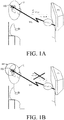
- FIG. 1A illustrates the problem when direct and wirelessly transmitted sound from a TV (TV) is transmitted to a hearing aid user (U) via a wireless link (WL).
- TV TV
- U hearing aid user
- WL wireless link
- the hearing aid user (U) is exposed to both the audio presented via the television's loudspeakers (propagated via an acoustic path) as well as the wirelessly streamed audio signal (termed direct representation of the audio signal).
- the signals are not fully time aligned when received in the hearing device (HD), the quality of the resulting sound of the mixture between the acoustically propagated and the wirelessly streamed audio signal is degraded.
- a simple solution would be to turn off the hearing aid microphones while the user is watching television, hereby only exposing the hearing aid user to the wirelessly transmitted television signal.
- This solution has the disadvantage that it prevents the hearing aid user from listening to other sounds of interest.
- Another solution would be to adjust delay of the acoustically propagated sound or the delay of the wireless sound in order to align the two signals.
- the wireless sound may even be subtracted from the acoustically propagated sound in order to remove the television signal from the microphone signal. It is however not easy to estimate the correct delay as the delay changes with the distance between the hearing aids and the television.
- FIG. 1B illustrates a solution to the problem of FIG. 1A .
- a beamformer is used to cancel the television signal recorded by the hearing aid microphones (cf. beam pattern BP in FIG. 1B ).
- an adaptive spatial filter able to cancel the sound in the direction of the television can be created.
- the adaptive filter takes advantage of the wirelessly streamed television signal. We hereby know the signal we would like to remove in the recorded microphone signals. We may e.g. find the spatial filter that minimizes the correlation between the acoustically propagated sound and the wirelessly transmitted sound under the constraint that noise from e.g. the side is unaltered.
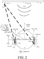
- FIG. 2 illustrates the same situation as shown in 1A, 1B, but where a specific (localized) sound source (AS), in addition to the sound from the television set (TV), is present in the environment of the user (U) of a (possibly binaural) hearing system according to the present disclosure.
- the sound source (S) e.g. a person speaking, is located at a distance d from the user and has a direction-of-arrival (DoA. REF-DIR AS ) defined (in a horizontal plane) by angle ⁇ relative to a reference direction, here a look direction (LOOK-DIR) of the user.
- the look direction is adaptively estimated, whenever sound of interest is detected as not being part of the television signal.
- the sound source (AS) provides acoustic sound a(n), n being a time index, (as indicated in FIG. 2 by three dashed arcs denoted a(n) ).
- the television set (TV) is located in front of the user ( U ) in a look direction (LOOK-DIR) of the user, and the TV-sound, s(n), produced by a loudspeaker (TV-SP) forming part of or connected to the TV set, is shown to arrive at the user from this direction (indicated by three dashed arcs denoted s(n) ).
- a transmitter transmits the (clean) TV-sound, s(n), wirelessly to the left and right hearing devices (HD L , HD R ) of the hearing system, as indicated by dashed arrows from TV-transmitter (TV-Tx) to the left and right hearing devices (HD L , HD R ).
- FIG. 2 schematically illustrates a geometrical arrangement of two sound sources ( AS, TV-SP ) relative to a hearing system comprising left and right hearing devices ( HD L , HD R ) when located on the head at or in left ( Left ear ) and right ( Right ear ) ears, respectively, of a user ( U ).
- Front and rear directions and front and rear half planes of space are defined relative to the user ( U ) and determined by the look direction ( LOOK-DIR, dashed arrow) of the user (here defined by the user's nose ( NOSE )) and a (vertical) reference plane through the user's ears (solid line perpendicular to the look direction ( LOOK-DIR )).
- the left and right hearing devices each comprise a BTE-part located at or behind-the-ear of the user.
- each BTE-part comprises two microphones, a front located microphone ( FM L , FM R ) and a rear located microphone ( RM L , RM R ) of the left and right hearing devices, respectively.
- the front and rear microphones on each BTE-part are spaced a distance ⁇ L M apart along a line (substantially) parallel to the look direction (LOOK-DIR), see dotted lines REF-DIR L and REF-DIR R , respectively.
- the two sets of microphones ( FM L , RML), ( FM R , RM R ) are spaced a distance L E2E apart (e.g. defined by the head of the user, ear-to-ear).
- the left and right hearing devices ( HD L , HD R ) each comprises appropriate antenna and transceiver circuitry for wirelessly receiving the TV-sound signal s(n).
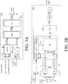
- FIG. 3A illustrates a hearing device (HD) according to a first embodiment of the present disclosure.
- the hearing device is adapted for wirelessly receiving an audio signal s(n) from an audio source (TV) in the vicinity of the user (U) wearing the hearing device (HD), e.g. from a TV-set as illustrated in FIG. 1A, 1B and 2 .
- the hearing device (HD) e.g.
- a hearing aid is adapted for being located at or in an ear of a user and/or for being fully or partially implanted in the head of the user.
- the hearing device comprises a fixed or adaptive filtering unit (Ada-BF) and a mixing unit (MIX) for mixing a wirelessly received TV-sound signal s(n) with signals from one or more sound sources in the environment (other than the TV-sound).
- the hearing device (HD) comprises a multitude of input units (here microphones M 1 , M 2 ), each providing an electric input signal x 1 (n), x 2 (n), representing a mixture of an audio signal from an audio signal source and possibly acoustic signals from other acoustic signal sources around the hearing device as received at the input unit in question.
- the hearing device (HD) further comprises a wireless receiver comprising appropriate antenna and transceiver circuitry (ANT, xTU) for receiving a wirelessly transmitted TV-signal (denoted TV-sound signal in FIG. 3A ), and providing a direct representation s(n) of the audio signal from the TV.
- ANT, xTU appropriate antenna and transceiver circuitry
- the (e.g. adaptive) beamformer filtering unit receives the multitude of electric input signals x 1 (n), x 2 (n), comprising the total acoustically propagated signal as received at 1 st and 2 nd microphones, and the wirelessly received TV-sound signal s(n), and is configured to provide a beamformed signal ⁇ (n) representing an estimate of the acoustic signal at the hearing device with components originating from the original signal s(n) removed.
- the beamformer filtering unit (Ada-BF) comprises a fixed beamformer configured to provide that sound from the direction from the hearing device to the audio signal source (e.g. the look direction of the user) is cancelled or attenuated compared to other directions in said beamformed signal. This is illustrated in FIG. 3A by ignoring the dotted arrow from wirelessly received audio signal s(n) to the beamformer filtering unit (Ada-BF).
- the beamformer filtering unit (Ada-BF) comprises an adaptive beamformer.
- the adaptive beamformer filtering unit (Ada-BF) is configured to determine the spatial filter (beamformer filtering coefficients) that minimizes the correlation between the acoustically received sound and the wirelessly received sound under the constraint that noise from a direction of a sound source of interest (e.g. AS in FIG. 2 ) in the environment, e.g. from the side, is unaltered. This is illustrated in FIG. 3A by the dotted arrow from wirelessly received audio signal s(n) to the (adaptive) beamformer filtering unit (Ada-BF).
- a sound source of interest e.g. AS in FIG. 2
- the combination unit implemented as mixing unit (MIX), for providing a mixed signal sa(n) comprising a combination (e.g. a weighted combination) of the wirelessly received (direct representation of the) audio signal s(n) and the beamformed signal ⁇ (n) (devoid of the TV-signal), or signals originating therefrom.
- MIX mixing unit
- the hearing device (HD) further comprises a processor (SPU) for processing the mixed signal sa(n) and providing a processed signal out out.
- a processor SPU for processing the mixed signal sa(n) and providing a processed signal out out.
- the combination unit (MIX) and the processor (SPU) form part of a signal processor (PRO).
- the hearing device (HD) further comprises an output unit (here loudspeaker SP) for presenting stimuli perceivable to the user as sound based on the processed signal out (here as sound, denoted Mixed sound in FIG. 3A ).
- an output unit here loudspeaker SP for presenting stimuli perceivable to the user as sound based on the processed signal out (here as sound, denoted Mixed sound in FIG. 3A ).
- FIG. 3B shows a hearing device (HD) according to a second embodiment of the present disclosure.
- the hearing device (HD) of FIG. 3B comprises the same functional elements as described in connection with FIG. 3A .
- IT l input transducer
- AFB analysis filter bank
- the adaptive filtering unit may e.g. comprise a minimum variance distortionless response (MVDR) beamformer, e.g. implemented as a generalized sidelobe canceller (GSC) structure.
- MVDR minimum variance distortionless response
- GSC generalized sidelobe canceller
- the adaptive filtering unit (Ada-BF) comprises a control unit (CONT) for receiving and/or estimating a location of and/or direction to relevant sound sources in the environment.
- the (Ada-BF) receives the wirelessly streamed version s of the audio signal (e.g. a TV-signal).
- the beamformer control signal CBF from the control unit (CONT) may comprise information about direction(s) to the sound source(s) of interest (AS in FIG. 2 ) in the environment (other than the audio sound source (TV in FIG. 2 ).
- Other information that may be advantageously provided by or from the control unit relate to the presence of speech in the signal received from the audio sound source (TV).
- Such information may be used to update noise information (e.g. represented by an inter-microphone noise correlation matrix C a , including 'noise' from the sound source(s) of interest (AS)) when the no speech is present in the signal received from the audio sound source (TV).
- the control unit (CONT) comprises a voice activity detector (WLD) for detecting time segments of the wirelessly streamed version s of the audio signal estimated to comprise speech and no speech, respectively (e.g. with a certain probability). This is relatively simple, since a clean version s of the audio signal is available (assuming that the audio signal is of sufficient quality).
- the control unit (CONT) comprises a memory MEM, e.g. for storing initial (e.g. predefined) values of a location of, or a direction to, one or more sound sources (AS) of interest to the user.
- beamformer filtering weights e.g. w mvdr (k, m)
- the beamformer control signal CBF may comprise such current beamformer filtering weights determined by the control unit (CONT).
- a movement sensor such as a gyroscope, an accelerometer or a magnetometer.
- the hearing device further comprises a signal processor (PRO) for providing a processed frequency sub-band signal OUT based on the wirelessly received audio signal s and the environment signal ⁇ .
- the signal processor (PRO) may e.g. be configured to execute a number of processing algorithms (e.g. for applying a frequency and level dependent gain (or attenuation) to the input signal(s), e.g. to compensate for a hearing impairment of the user, and/or to compensate for a noisy environment) for enhancing the input signals s, ⁇ .
- the signal processor (PRO) may comprise other functions, e.g. one or more of noise reduction, feedback cancellation, compressive amplification, etc.
- the signal processor may e.g.
- the signal processor is configured to combine the input signals, s, ⁇ , before other processing algorithms are applied to the combined signal.
- the hearing device further comprises an output unit (OU) for converting the frequency sub-band signal OUT to stimuli perceivable by a user as sound representing the wirelessly received audio sound signal and acoustic signals from the environment ( Mixed sound in FIG. 2 ).
- the output unit (OU) comprises synthesis filter bank (SFB) for converting the frequency sub-band signal OUT to a time domain signal out, and an output transducer (OT, e.g. a loudspeaker or a vibrator of a bone-conducting hearing device) for converting the time domain signal out to the stimuli perceivable by a user as sound.
- synthesis filter bank SFB
- OT output transducer
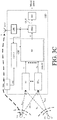
- FIG. 3C shows a hearing device (HD) according to a third embodiment of the present disclosure.
- the hearing device comprises the same functional units as described in connection with FIG. 3A, and 3B , but a specific frequency sub-band representation of signals is not illustrated in FIG. 3C ; signal processing may be performed in the time domain or in the time-frequency domain or mixed depending on the function to be performed.
- the hearing device (HD) of FIG. 3C comprises a user interface (UI) allowing a user to influence the adaptive beamformer filtering unit (Ada-BF).
- UI user interface
- the hearing device is configured to allow the user to indicate a location or direction of arrival (DoA) of sound from the audio sound source (TV) and/or from other sound source(s) (AS) of interest in the environment via the user interface, cf. user control signal UC (cf. e.g. also FIG. 5A, 5B ).
- DoA location or direction of arrival
- AS sound source(s)
- TV audio sound source
- AS environment sound source
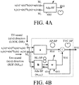
- FIG. 4A shows a top level block diagram of an adaptive filtering scheme (embodied in fixed or adaptive beamformer filtering unit Ada-BF ) for removing the direct (acoustically propagated) TV sound from an audio signal to be presented the user via a hearing device comprising a microphone array (here comprising two microphones M 1 , M 2 ).
- the fixed version of the beamformer filtering unit (Ada-BF) is configured to provide that sound from the direction from the hearing device to the audio signal source (e.g. the look direction of the user) is cancelled or attenuated compared to other directions in said beamformed signal.
- the adaptive beamformer filtering unit (Ada-BF) is configured to determine the spatial filter (beamformer filtering coefficients) that minimizes the correlation between the acoustically received sound (x 1 (n) , x 2 (n) ) and the wirelessly received sound ( s(n) ) under the constraint that noise from a direction of a sound source of interest (e.g. AS in FIG. 2 ) in the environment, e.g. from the side, is unaltered.
- a sound source of interest e.g. AS in FIG. 2
- the basic function of the adaptive beamformer filtering unit (Ada-BF) shown in FIG. 4A in a hearing device (HD) according to the present disclosure is described in connection with FIG. 3A .
- the minimum variance distortionless response (MVDR) beamformer is widely used in microphone array signal processing. Ideally the MVDR beamformer keeps the signals from the target direction (also referred to as the look direction) unchanged, while attenuating sound signals from other directions maximally.
- the generalized sidelobe canceller (GSC) structure is an equivalent representation of the MVDR beamformer offering computational and numerical advantages over a direct implementation in its original form.
- FIG. 4B and 4C illustrate first and second embodiments of the adaptive filtering scheme, where a GSC-type beamformer is used to cancel the television signal recorded by the hearing aid microphones, while attending to a nearby sound source from the environment (other than the TV-sound).
- the wirelessly received signal s(n) is used in the estimation of the environment sound ⁇ (n) (exclusive of the TV-sound).
- FIG. 4B and 4C illustrate possible adaptive filtering schemes, where the spatial filter (Ada-BF) adapts towards cancelling the received wireless sound s from the microphone signals x 1 , x 2 .
- the adaptive spatial filter (Ada-BF ( w GSC )) may e.g. be or comprise an MVDR beamformer. Assuming that the television signal mainly is in front of the listener (cf. Front in FIG. 2 ), the look direction (cf. LOOK-DIR in FIG. 2 ) corresponding to a direction from which the beamformed signal is undistorted can be in any other appropriate direction, e.g. towards the side of the listener (cf. bold arrow denoted Env.
- the wireless signal s may also be used for a voice activity detector such that the adaptive spatial filter w only is allowed to adapt, when the wireless signal is active (e.g. comprising speech), cf. input s(n) to the adaptive beamformer w.
- the look vector d AS representing transfer functions from an environment sound source (AS, other than the TV) to each of the microphones ( M 1 , M 2 ) may be updated in energetic time-frequency frames, where the TV sound s(n) is not active.
- FIG. 4A, 4B , 4C The following notation is used in FIG. 4A, 4B , 4C :
- the adaptive beamformer filtering unit (Ada-BF ( w GSC )) of FIG. 4B is an embodiment of FIG. 4A .
- the beamformer filtering unit of FIG. 4B (and 4C ) comprises functional units a, B and w and +.
- the unit a represents an all pass beamformer unit configured to provide an omni-diectional beam pattern (AP-BP).
- the output signal â(n) is typically represented by a delay-sum beamformer.
- the unit B comprises a blocking filter, e.g. configured to attenuate signals from the side(s) of the user (+/- 90°, perpendicular to the look direction (LOOK-DIR) towards the audio source, here the TV).
- the look direction is adaptively determined.
- the output signal b(n) represents a target cancelling beamformer.
- a and B are orthogonal.
- the combination unit subtracts the estimate ⁇ (n) of the acoustic part of the TV-signal from the estimate â(n) of the environment sound source of interest (other than the TV), and provides resulting signal ⁇ (n) representing an estimation of the environment sound (exclusive of the TV-sound), cf. beam pattern TVC-BP.
- the adaptive beamformer filtering unit (Ada-BF ( w GSC )) of FIG. 4C is similar to the embodiment of FIG. 4B .
- 4C further comprises a wireless receiver comprising appropriate antenna and transceiver circuitry (ANT, xTU) for receiving a wirelessly transmitted TV-signal (denoted TV-sound signal in FIG. 3A ), and providing the direct representation s(n) of the audio signal from the TV.
- ANT, xTU appropriate antenna and transceiver circuitry
- all three input signals x 1 , x 2 , s are input to both beamformer blocks a and B.
- the wireless signal s is delay compensated in order to ensure that the wireless signal and the microphone signals are correlated, cf. unit DEL (representing a delay of an appropriate number of time frames, inserted in the microphone paths and/or the wireless reception path, respectively, and providing delay compensated signals x 1 ', x 2 ', and s' , respectively.
- the delay unit may e.g. represent estimated delays (hereby taking transmission delay as well as acoustic propagation delay into account).
- B is a blocking matrix of size 3x2, and a is a 3x1 matrix.
- a is represented by a matrix (vector) [d AS,1 d* AS,1 , d* AS,1 d AS,2 , 0] T , where T represents transposition.
- one column of B is represented by [(1-d AS,1 d* AS,1 ), -d* AS ,d AS,2 , 0], and the other column of B is represented by [0,0,1] T .
- 2 , l 1, 2, and it is assumed that
- 2 1.
- FIG. 5A illustrates an embodiment of a hearing system according to the present disclosure.
- the hearing system comprises left and right hearing devices in communication with an auxiliary device, e.g. a remote control device, e.g. a communication device, such as a cellular telephone or similar device capable of establishing a communication link to one or both of the left and right hearing devices.
- auxiliary device e.g. a remote control device, e.g. a communication device, such as a cellular telephone or similar device capable of establishing a communication link to one or both of the left and right hearing devices.
- a remote control device e.g. a communication device, such as a cellular telephone or similar device capable of establishing a communication link to one or both of the left and right hearing devices.
- FIG. 5A, 5B shows an application scenario comprising an embodiment of a binaural hearing system comprising first and second hearing devices (HD R , HD L ), e.g. hearing aids, and an auxiliary device (Aux) according to the present disclosure.
- the auxiliary device (Aux) comprises a cellular telephone, e.g. a SmartPhone.
- the hearing devices and the auxiliary device are configured to establish wireless links (WL) between them, e.g. in the form of digital transmission links according to the Bluetooth standard (e.g. Bluetooth Low Energy).
- the links may alternatively be implemented in any other convenient wireless and/or wired manner, and according to any appropriate modulation type or transmission standard, possibly different for different audio sources.
- the auxiliary device (e.g. a SmartPhone) of FIG. 5A, 5B comprises a user interface (UI) providing the function of a remote control of the hearing system, e.g. for changing program or operating parameters (e.g. volume) in the hearing device(s), etc.
- the user interface (UI) of FIG. 5B illustrates an APP (denoted 'TV Audio APP' ) for selecting a mode of operation of the hearing system where audio signals streamed to the left and right hearing devices (HD L , HD R ) are mixed with signals from the environment.
- the APP allows a user to select a manual ( Manual ), and an automatic ( Automatic ) mode (cf. Select source signals AS, TV ). In the screen of FIG.
- the manual mode of operation has been selected as indicated by the left solid 'tick-box' and the bold face indication Manual.
- the direction of arrival of a target sound source among the acoustic around sources (AS, other than the audio source, e.g. from the TV) and the direction to the audio sound source (TV) can be manually selected, e.g. via the touch sensitive screen.
- the result is displayed in the screen by circular and square symbols denoted AS and TV, respectively, and bold solid and dashed arrows denoted DoA AS and DoA TV , respectively, schematically shown relative to the head of the user to reflect their approximate location. This is indicated by the text Manually determined DoA to sources (AS), (TV) in the lower part of the screen in FIG.
- an estimate of the location of the target sound source(s) may be indicated by the user via the user interface (UI), e.g. by moving a sound source symbol (circular symbol denoted AS, and rectangular symbol denoted TV in FIG. 5B ) to an estimated location on the screen relative to the user's head.
- UI user interface
- AS circular symbol denoted
- TV rectangular symbol denoted TV in FIG. 5B
- default directions to the sound sources AS and TV are assumed by the hearing device or hearing system (e.g. as stored in a memory (MEM) of the hearing device (or hearing system)).
- the calculations of the direction of arrival are performed in the auxiliary device, e.g. according to a predefined algorithm, such as e.g. described in [Farmani et al.; 2017a].
- the hearing system is configured to apply appropriate transfer functions to the wirelessly received (streamed) audio signal (from the TV) to reflect its direction of arrival. This has the advantage of providing a sensation of the spatial origin of the streamed signal to the user.
- the hearing device (HD L , HD R ) are shown in FIG. 5A as devices mounted at the ear (behind the ear) of a user (U). Other styles may be used, e.g. located completely in the ear (e.g. in the ear canal), fully or partly implanted in the head, etc.
- Each of the hearing instruments comprise a wireless transceiver to establish an interaural wireless link (IA-WL) between the hearing devices, here e.g. based on inductive communication.
- Each of the hearing devices further comprises a transceiver for establishing a wireless link (WL, e.g.
- auxiliary device based on radiated fields (RF)) to the auxiliary device (Aux), at least for receiving and/or transmitting signals (CNT R , CNT L ), e.g. control signals, e.g. information signals (e.g. DoA), e.g. including audio signals.
- the transceivers are indicated by RF-IA-Rx/Tx-R and RF-IA-Rx/Tx-L in the right and left hearing devices, respectively.
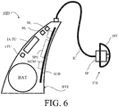
- FIG. 6 shows an exemplary (schematic) physical implementation of a hearing device according to the present disclosure.
- the hearing device (HD) shown in FIG. 6 e.g. a hearing aid, is of a particular style (sometimes termed receiver-in-the ear, or RITE, style) comprising a BTE-part (BTE) adapted for being located at or behind an ear of a user and an ITE-part (ITE) adapted for being located in or at an ear canal of a user's ear and comprising a receiver (loudspeaker, SP).
- BTE-part and the ITE-part are connected (e.g. electrically connected) by a connecting element (IC).
- IC connecting element
- the BTE part comprises two input transducers (e.g. microphones) (M 1 , M 2 , e.g. corresponding to front and rear microphones, respectively), each for providing an electric input audio signal representative of an input sound signal (e.g. a 'noisy' version of the audio signal).
- the hearing device (HD) comprises three or more input transducers (e.g. microphones).
- the hearing device of FIG. 6 further comprises two wireless transceivers (IA-TU, xTU) for availing reception and/or transmission of respective audio and/or information or control signals.
- xTU is configured to receive an essentially noise-free version of the audio signal from the audio sound source (here a TV, see FIG. 1A, 1B , 2 ), and IA-TU is configured to transmit or receive audio signals (e.g. microphone signals, or (e.g. band-limited) parts thereof) and/or to transmit or receive information (e.g. related to the localization of the audio sound source (e.g. TV in FIG. 5B ) and/or a preferred acoustic sound source in the user's environment (e.g. AS in FIG. 5B ), e.g. a DoA) from a contralateral hearing device of a binaural hearing system, e.g.
- audio signals e.g. microphone signals, or (e.g. band-limited) parts thereof
- information e.g. related to the localization of the audio sound source (e.g. TV in FIG. 5B ) and/or a preferred acoustic sound source in the user's environment (e.g
- the hearing device (HD) comprises a substrate SUB whereon a number of electronic components are mounted, including a memory (MEM), e.g. storing default relative transfer functions RTF(k, ⁇ ) from a reference microphone to any of the further microphones of the hearing system.
- the BTE-part further comprises a configurable signal processor (SPU, PRO) adapted to access the memory (MEM) and for selecting and processing one or more of the electric input audio signals and/or one or more of the directly received auxiliary audio input signals, based on a current parameter setting (and/or on inputs from a user interface).
- the configurable signal processor (SPU, PRO) provides an enhanced audio signal, which may be presented to a user or further processed or transmitted to another device as the case may be.
- the hearing device (HD) further comprises an output unit (e.g. an output transducer or electrodes of a cochlear implant) providing an enhanced output signal as stimuli perceivable by the user as sound based on said enhanced audio signal or a signal derived therefrom
- an output unit e.g. an output transducer or electrodes of a cochlear implant
- the ITE part comprises the output unit in the form of a loudspeaker (receiver) (SP) for converting an electric signal to an acoustic signal.
- the ITE-part further comprises a guiding element, e.g. a dome, (DO) for guiding and positioning the ITE-part in the ear canal of the user.
- the hearing device (HA) exemplified in FIG. 6 is a portable device and further comprises a battery (BAT), e.g. a rechargeable battery, for energizing electronic components of the BTE- and ITE-parts.
- BAT battery
- e.g. a rechargeable battery for energizing electronic components of the BTE- and ITE-parts.
- the hearing device e.g. a hearing aid (e.g. the signal processor)
- a hearing aid e.g. the signal processor
- the hearing device is adapted to provide a frequency dependent gain and/or a level dependent compression and/or a transposition (with or without frequency compression) of one or more source frequency ranges to one or more target frequency ranges, e.g. to compensate for a hearing impairment of a user.
- a hearing system according to the present disclosure may e.g. comprise left and right hearing devices as shown in FIG. 6 .
- FIG. 7 shows a method of operating a hearing device according to an embodiment of the disclosure/
- the hearing device e.g. a hearing aid
- the hearing device may be adapted for being located at or in an ear of a user and/or for being fully or partially implanted in the head of the user is furthermore provided by the present application.
- the method comprises
- connection or “coupled” as used herein may include wirelessly connected or coupled.
- the term “and/or” includes any and all combinations of one or more of the associated listed items. The steps of any disclosed method is not limited to the exact order stated herein, unless expressly stated otherwise.
Landscapes
- Engineering & Computer Science (AREA)
- Health & Medical Sciences (AREA)
- General Health & Medical Sciences (AREA)
- Neurosurgery (AREA)
- Otolaryngology (AREA)
- Physics & Mathematics (AREA)
- Acoustics & Sound (AREA)
- Signal Processing (AREA)
- Computer Networks & Wireless Communication (AREA)
- Circuit For Audible Band Transducer (AREA)
Claims (16)
- Hörgerät (hearing device - HD), z. B. eine Hörhilfe, das dazu angepasst ist, an oder in einem Ohr eines Benutzers (user - U) angeordnet zu sein und/oder in dem Kopf des Benutzers (U) implantiert zu sein, wobei das Hörgerät (HD) Folgendes umfasst:• eine Vielzahl von Eingangseinheiten (M1, M2; IU1, ..., IUM), wobei jede ein elektrisches Eingangssignal (x1(n), x2(n); x1, ..., xM; X1, ..., XM) bereitstellt, das eine Mischung eines Audiosignals von einer Audiosignalquelle (TV) und möglicherweise Akustiksignalen von anderen Akustiksignalquellen um das Hörgerät (HD), wie an den betreffenden Eingangseinheiten (IU1, .., IUM) empfangen, darstellt;• einen drahtlosen Empfänger (xTU) zum Empfangen und Bereitstellen einer direkten Darstellung (s(n); s) des Audiosignals;• eine Strahlformerfiltereinheit (Ada-BF), die dazu konfiguriert ist, die Vielzahl von elektrischen Eingangssignalen (x1(n), x2(n); x1, ..., xM; X1, ..., XM) zu empfangen, und die ein strahlgeformtes Signal (ä(n), Ã) bereitstellt;• eine Kombinationseinheit (MIX; PRO) zum Bereitstellen eines gemischten Signals (sa(n); OUT), umfassend eine Kombination der direkten Darstellung (s(n); s) des Audiosignals und des strahlgeformten Signals (ä(n), Ã), oder von Signalen, die daher stammen;• eine Ausgangseinheit (SP; OT) zum Darstellen von Reizen, die durch den Benutzer (U) wahrnehmbar sind, als Schall basierend auf dem gemischten Signal (sa(n); OUT),
DADURCH GEKENNZEICHNET, DASS
die Strahlformerfiltereinheit (Ada-BF) einen Audiosignalunterdrückungsstrahlformer umfasst, der dazu konfiguriert ist, dafür zu sorgen, dass Schall aus einer Richtung von dem Hörgerät (HD) zu der Audiosignalquelle (TV) im Vergleich zu anderen Richtungen in dem strahlgeformten Signal (ã(n), Ã) unterdrückt oder gedämpft wird, wobei die Strahlformerfiltereinheit (Ada-BF) einen adaptiven Filter umfasst, der dazu konfiguriert ist, einen räumlichen Filter, z. B. einen MVDR-Strahlformer, zu bestimmen, der die Korrelation zwischen akustisch ausgebreitetem Schall, der durch (ein) elektrische(s) Eingangssignal(e) (x1(n), x2(n); x1, ..., xM; X1, ..., XM) dargestellt ist, und drahtlos empfangenem Schall, der durch die direkte Darstellung (s(n); s) des Audiosignals dargestellt ist, unter der Einschränkung minimiert, dass Ton aus einer Richtung (REF-DIRAS, θ) zu einer anderen Schallquelle (AS) von Interesse, z. B. an der Seite des Benutzers, nicht verändert ist, und ein strahlgeformtes Signal (ã; ã(n); Ã) basierend darauf bereitzustellen. - Hörgerät (HD) nach Anspruch 1, wobei die Kombinationseinheit (MIX; PRO) eine Gewichtungseinheit ist, die das gemischte Signals (sa(n); OUT) als eine gewichtete Kombination der direkten Darstellung (s(n); s) des Audiosignals und des strahlgeformten Signals (ã(n), Ã), oder von Signalen, die daher stammen, bereitstellt.
- Hörgerät (HD) nach Anspruch 1 oder 2, wobei die Strahlformerfiltereinheit (Ada-BF) einen MVDR-Strahlformer umfasst.
- Hörgerät (HD) nach einem der Ansprüche 1-3, umfassend einen Drahtlossignaldetektor, der dazu konfiguriert ist, zu erkennen, ob eine drahtlose direkte Darstellung des Audiosignals zu einem gegebenen Zeitpunkt durch das Hörgerät (HD) empfangen wird oder nicht, und dazu, ein Detektorsignal bereitzustellen, das dies angibt.
- Hörgerät (HD) nach einem der Ansprüche 1-4, umfassend eine Steuereinheit (control unit - CONT) zum Empfangen der direkten Darstellung (s(n); s) des Audiosignals und zum Bestimmen oder Definieren einer Richtung (LOOK-DIR; DoATV) von dem Hörgerät (HD) zu der Audiosignalquelle (TV, TV-SP).
- Hörgerät (HD) nach einem der Ansprüche 1-5, umfassend eine Steuerung, die dazu konfiguriert ist, die Korrelation zwischen dem akustisch ausgebreiteten Schall und nur dem drahtlos empfangenen Schall, wenn das drahtlose Signal durch das Hörgerät (HD) empfangen wird, zu minimieren.
- Hörgerät (HD) nach einem der Ansprüche 1-6, umfassend eine Benutzerschnittstelle (user interface - UI), die es einem Benutzer (U) ermöglicht, einen Standort oder eine Ankunftsrichtung (LOOK-DIR, REF-DIRAS; DoATV, DOAAS) von Schall von der Audioschallquelle (TV) und/oder von (einer) anderen Schallquelle(n) von Interesse (AS) in der Umgebung anzugeben.
- Hörgerät (HD) nach einem der Ansprüche 1-7, umfassend einen Bewegungssensor zum Verfolgen einer Kopfbewegung oder der dazu konfiguriert ist, Daten zur Kopfbewegung von einer anderen Vorrichtung zu empfangen, und wobei die Steuereinheit (CONT) dazu konfiguriert ist, Strahlformerfilterkoeffizienten in Abhängigkeit von erkannten Kopfbewegungen zu aktualisieren.
- Hörgerät (HD) nach einem der Ansprüche 1-8, umfassend eine Hörhilfe, ein Headset, einen Ohrhörer, eine Ohrschutzvorrichtung oder eine Kombination davon.
- Hörgerät (HD) nach einem der Ansprüche 1-9, das dazu konfiguriert ist, das Audiosignal von der Audiosignalquelle (TV) in dem strahlgeformten Signal (ä(n), Ã) in Abhängigkeit von der direkten Darstellung (s(n); s) des Audiosignals oder von einem Schätzwert oder einer Angabe einer Richtung (LOOK-DIR; DoATV) zu der Audiosignalquelle (TV) zu unterdrücken oder zu dämpfen.
- Hörsystem, umfassend ein linkes und ein rechtes Hörgerät (HDL, HDR) gemäß einem der Ansprüche 1-10 und eine Hilfsvorrichtung (auxiliary device - Aux), wobei das Hörsystem dazu angepasst ist, eine Kommunikationsverbindung (WL) zwischen den Hörgeräten (HDL, HDR) und der Hilfsvorrichtung (Aux) herzustellen, um dafür zu sorgen, dass Informationen (CNTL, CNTR), z. B. Steuer- und Statussignale, möglicherweise Audiosignale, von einem zum anderen ausgetauscht oder weitergeleitet werden können.
- Verfahren zum Betreiben eines Hörgeräts (HD), z. B. eine Hörhilfe, das dazu angepasst ist, an oder in einem Ohr eines Benutzers (U) angeordnet zu werden und/oder in dem Kopf des Benutzers (U) implantiert zu werden, wobei das Verfahren Folgendes umfasst:• Bereitstellen einer Vielzahl von elektrischen Eingangssignalen (x1(n), x2(n); x1, ..., xM; X1, ..., XM), wobei jedes eine Mischung eines Audiosignals von einer Audiosignalquelle (TV) und möglicherweise anderen Akustiksignalen von anderen Akustiksignalquellen um das Hörgerät, wie an gegebenen Eingangseinheiten (M1, M2; IU1, ..., IUM) des Hörgeräts (HD) empfangen, darstellt;• drahtloses Empfangen und Bereitstellen einer direkten Darstellung (s(n); s) des Audiosignals;• Bereitstellen eines strahlgeformten Signals (ã(n), Ã) in Abhängigkeit von der Vielzahl von elektrischen Eingangssignalen (x1(n), x2(n); x1, ..., xM; X1, ..., XM);• Bereitstellen eines gemischten Signals (sa(n); OUT), umfassend eine Kombination der direkten Darstellung (s(n); s) des Audiosignals und des strahlgeformten Signals (ã(n), Ã), oder von Signalen, die daher stammen;• Darstellen von Reizen, die durch den Benutzer (U) wahrnehmbar sind, als Schall basierend auf dem gemischten Signal (sa(n); OUT),• DADURCH GEKENNZEICHNET, dass dafür gesorgt wird, dass Schalls aus der Richtung (LOOK-DIR; DoATV) von dem Hörgerät (HD) zu der Audiosignalquelle (TV) im Vergleich zu anderen Richtungen in dem strahlgeformten Signal (ä(n), Ã) durch Folgendes unterdrückt oder gedämpft wird:∘ adaptives Bestimmen eines räumlichen Filters, z. B. eines MVDR-Strahlformers, der die Korrelation zwischen akustisch ausgebreitetem Schall, der durch das/die elektrische(n) Eingangssignal(e) (x1(n), x2(n); x1, ..., xM; X1, ..., XM) dargestellt ist, und drahtlos empfangenem Schall, der durch die direkte Darstellung (s(n); s) des Audiosignals dargestellt ist, unter der Einschränkung minimiert, dass Ton aus einer Richtung (REF-DIRAS; θ) zu einer anderen Schallquelle (AS) von Interesse, z. B. an der Seite des Benutzers, nicht verändert ist, und∘ Bereitstellen eines strahlgeformten Signals (ã; ã(n); Ã) basierend darauf.
- Verfahren nach Anspruch 12, umfassend Unterdrücken oder Dämpfen des Audiosignal von der Audiosignalquelle (TV) in dem strahlgeformten Signal (ã(n), Ã) in Abhängigkeit von der direkten Darstellung (s(n); s) des Audiosignals oder von einem Schätzwert oder einer Angabe einer Richtung (LOOK-DIR; DoATV) zu der Audiosignalquelle (TV).
- Verwendung eines Hörgeräts (HD) nach einem der Ansprüche 1-10 in einer Hörhilfe.
- Datenverarbeitungssystem, umfassend einen Prozessor und Programmcodemittel, um den Prozessor zu veranlassen, das Verfahren nach Anspruch 12 oder 13 durchzuführen.
- Computerprogramm, umfassend Anweisungen, die, wenn das Programm von einem Computer ausgeführt wird, den Computer dazu veranlassen, das Verfahren nach Anspruch 12 oder 13 auszuführen.
Applications Claiming Priority (1)
| Application Number | Priority Date | Filing Date | Title |
|---|---|---|---|
| EP17160209 | 2017-03-09 |
Publications (2)
| Publication Number | Publication Date |
|---|---|
| EP3373603A1 EP3373603A1 (de) | 2018-09-12 |
| EP3373603B1 true EP3373603B1 (de) | 2020-07-08 |
Family
ID=58266459
Family Applications (1)
| Application Number | Title | Priority Date | Filing Date |
|---|---|---|---|
| EP18160039.6A Active EP3373603B1 (de) | 2017-03-09 | 2018-03-05 | Hörgerät mit einem drahtlosen empfänger von schall |
Country Status (4)
| Country | Link |
|---|---|
| US (1) | US10582314B2 (de) |
| EP (1) | EP3373603B1 (de) |
| CN (1) | CN108574922B (de) |
| DK (1) | DK3373603T3 (de) |
Families Citing this family (13)
| Publication number | Priority date | Publication date | Assignee | Title |
|---|---|---|---|---|
| US10962780B2 (en) * | 2015-10-26 | 2021-03-30 | Microsoft Technology Licensing, Llc | Remote rendering for virtual images |
| US10555094B2 (en) * | 2017-03-29 | 2020-02-04 | Gn Hearing A/S | Hearing device with adaptive sub-band beamforming and related method |
| EP3534624B1 (de) * | 2018-02-28 | 2024-04-17 | Sivantos Pte. Ltd. | Verfahren zum betrieb eines hörgerätes |
| DE102018203907A1 (de) | 2018-02-28 | 2019-08-29 | Sivantos Pte. Ltd. | Verfahren zum Betrieb eines Hörgerätes |
| DK3588983T3 (da) * | 2018-06-25 | 2023-04-17 | Oticon As | Høreanordning tilpasset til at matche indgangstransducere ved anvendelse af stemmen af en bruger af høreanordningen |
| US11500610B2 (en) * | 2018-07-12 | 2022-11-15 | Dolby Laboratories Licensing Corporation | Transmission control for audio device using auxiliary signals |
| CN109787930A (zh) * | 2019-03-29 | 2019-05-21 | 苏州东奇信息科技股份有限公司 | 一种基于mppsk调制方式的抗脉冲干扰方法 |
| US10798499B1 (en) * | 2019-03-29 | 2020-10-06 | Sonova Ag | Accelerometer-based selection of an audio source for a hearing device |
| EP3751868A1 (de) * | 2019-06-12 | 2020-12-16 | Oticon A/s | Binaurales hörsystem mit frequenzübergang |
| EP4052385A1 (de) * | 2019-10-30 | 2022-09-07 | Starkey Laboratories, Inc. | Audiozubehör für eine strahllenkende gruppenantenne |
| DE102020207586A1 (de) * | 2020-06-18 | 2021-12-23 | Sivantos Pte. Ltd. | Hörsystem mit mindestens einem am Kopf des Nutzers getragenen Hörinstrument sowie Verfahren zum Betrieb eines solchen Hörsystems |
| EP4009322A3 (de) * | 2020-09-17 | 2022-06-15 | Orcam Technologies Ltd. | Systeme und verfahren zur selektiven dämpfung einer stimme |
| CN114040308B (zh) * | 2021-11-17 | 2023-06-30 | 郑州航空工业管理学院 | 一种基于情感增益的皮肤听声助听装置 |
Family Cites Families (19)
| Publication number | Priority date | Publication date | Assignee | Title |
|---|---|---|---|---|
| US6694034B2 (en) * | 2000-01-07 | 2004-02-17 | Etymotic Research, Inc. | Transmission detection and switch system for hearing improvement applications |
| DE10048354A1 (de) * | 2000-09-29 | 2002-05-08 | Siemens Audiologische Technik | Verfahren zum Betrieb eines Hörgerätesystems sowie Hörgerätesystem |
| DE102006018634B4 (de) * | 2006-04-21 | 2017-12-07 | Sivantos Gmbh | Hörgerät mit Quellentrennung und entsprechendes Verfahren |
| US8391523B2 (en) * | 2007-10-16 | 2013-03-05 | Phonak Ag | Method and system for wireless hearing assistance |
| US8170247B2 (en) * | 2009-06-24 | 2012-05-01 | Panasonic Corporation | Hearing aid |
| DK2360943T3 (da) * | 2009-12-29 | 2013-07-01 | Gn Resound As | Beamforming i høreapparater |
| JP5514698B2 (ja) * | 2010-11-04 | 2014-06-04 | パナソニック株式会社 | 補聴器 |
| DK2826262T3 (en) * | 2012-03-12 | 2016-07-04 | Sonova Ag | Method of operation of a hearing aid and of a hearing aid |
| DE102013212853A1 (de) * | 2013-07-02 | 2015-01-08 | Siemens Medical Instruments Pte. Ltd. | Erkennen von Hörsituationen mit unterschiedlichen Signalquellen |
| EP2843971B1 (de) * | 2013-09-02 | 2018-11-14 | Oticon A/s | Hörgerät mit Mikrofon im Gehörkanal |
| EP2928210A1 (de) * | 2014-04-03 | 2015-10-07 | Oticon A/s | Binaurales Hörgerätesystem mit binauraler Rauschunterdrückung |
| EP2999235B1 (de) * | 2014-09-17 | 2019-11-06 | Oticon A/s | Hörvorrichtung mit gsc-beamformer |
| EP3051844B1 (de) * | 2015-01-30 | 2017-11-15 | Oticon A/s | Binaurales Hörsystem |
| DK3057340T3 (da) * | 2015-02-13 | 2019-08-19 | Oticon As | Partnermikrofonenhed og et høresystem, der omfatter en partnermikrofonenhed |
| DK3101919T3 (da) * | 2015-06-02 | 2020-04-06 | Oticon As | Peer-to-peer høresystem |
| WO2017088909A1 (en) * | 2015-11-24 | 2017-06-01 | Sonova Ag | Method of operating a hearing aid and hearing aid operating according to such method |
| EP3270608B1 (de) * | 2016-07-15 | 2021-08-18 | GN Hearing A/S | Hörgerät mit adaptiver verarbeitung und zugehöriges verfahren |
| DE102017202480A1 (de) * | 2017-02-16 | 2018-08-16 | Sivantos Pte. Ltd. | Verfahren zum Betrieb einer Hörvorrichtung und Hörvorrichtung |
| US10687157B2 (en) * | 2017-10-16 | 2020-06-16 | Intricon Corporation | Head direction hearing assist switching |
-
2018
- 2018-03-05 EP EP18160039.6A patent/EP3373603B1/de active Active
- 2018-03-05 DK DK18160039.6T patent/DK3373603T3/da active
- 2018-03-08 US US15/915,322 patent/US10582314B2/en active Active
- 2018-03-09 CN CN201810196249.2A patent/CN108574922B/zh active Active
Non-Patent Citations (1)
| Title |
|---|
| None * |
Also Published As
| Publication number | Publication date |
|---|---|
| CN108574922A (zh) | 2018-09-25 |
| DK3373603T3 (da) | 2020-09-14 |
| US20180262847A1 (en) | 2018-09-13 |
| CN108574922B (zh) | 2021-08-24 |
| US10582314B2 (en) | 2020-03-03 |
| EP3373603A1 (de) | 2018-09-12 |
Similar Documents
| Publication | Publication Date | Title |
|---|---|---|
| EP3373603B1 (de) | Hörgerät mit einem drahtlosen empfänger von schall | |
| US10356536B2 (en) | Hearing device comprising an own voice detector | |
| US10728677B2 (en) | Hearing device and a binaural hearing system comprising a binaural noise reduction system | |
| EP3236672B1 (de) | Hörgerät mit einer strahlformerfiltrierungseinheit | |
| US9712928B2 (en) | Binaural hearing system | |
| US9860656B2 (en) | Hearing system comprising a separate microphone unit for picking up a users own voice | |
| EP3506658B1 (de) | Hörgerät mit einem zur platzierung am oder im gehörgang eines benutzers angepassten mikrofon | |
| EP3681175A1 (de) | Hörgerät mit direkter schallkompensation | |
| US10951995B2 (en) | Binaural level and/or gain estimator and a hearing system comprising a binaural level and/or gain estimator | |
| US11856357B2 (en) | Hearing device comprising a noise reduction system | |
| US20220256296A1 (en) | Binaural hearing system comprising frequency transition |
Legal Events
| Date | Code | Title | Description |
|---|---|---|---|
| PUAI | Public reference made under article 153(3) epc to a published international application that has entered the european phase |
Free format text: ORIGINAL CODE: 0009012 |
|
| STAA | Information on the status of an ep patent application or granted ep patent |
Free format text: STATUS: THE APPLICATION HAS BEEN PUBLISHED |
|
| AK | Designated contracting states |
Kind code of ref document: A1 Designated state(s): AL AT BE BG CH CY CZ DE DK EE ES FI FR GB GR HR HU IE IS IT LI LT LU LV MC MK MT NL NO PL PT RO RS SE SI SK SM TR |
|
| AX | Request for extension of the european patent |
Extension state: BA ME |
|
| STAA | Information on the status of an ep patent application or granted ep patent |
Free format text: STATUS: REQUEST FOR EXAMINATION WAS MADE |
|
| STAA | Information on the status of an ep patent application or granted ep patent |
Free format text: STATUS: EXAMINATION IS IN PROGRESS |
|
| 17P | Request for examination filed |
Effective date: 20190312 |
|
| RBV | Designated contracting states (corrected) |
Designated state(s): AL AT BE BG CH CY CZ DE DK EE ES FI FR GB GR HR HU IE IS IT LI LT LU LV MC MK MT NL NO PL PT RO RS SE SI SK SM TR |
|
| 17Q | First examination report despatched |
Effective date: 20190412 |
|
| GRAP | Despatch of communication of intention to grant a patent |
Free format text: ORIGINAL CODE: EPIDOSNIGR1 |
|
| STAA | Information on the status of an ep patent application or granted ep patent |
Free format text: STATUS: GRANT OF PATENT IS INTENDED |
|
| INTG | Intention to grant announced |
Effective date: 20200130 |
|
| GRAS | Grant fee paid |
Free format text: ORIGINAL CODE: EPIDOSNIGR3 |
|
| GRAA | (expected) grant |
Free format text: ORIGINAL CODE: 0009210 |
|
| STAA | Information on the status of an ep patent application or granted ep patent |
Free format text: STATUS: THE PATENT HAS BEEN GRANTED |
|
| AK | Designated contracting states |
Kind code of ref document: B1 Designated state(s): AL AT BE BG CH CY CZ DE DK EE ES FI FR GB GR HR HU IE IS IT LI LT LU LV MC MK MT NL NO PL PT RO RS SE SI SK SM TR |
|
| REG | Reference to a national code |
Ref country code: CH Ref legal event code: EP Ref country code: AT Ref legal event code: REF Ref document number: 1289785 Country of ref document: AT Kind code of ref document: T Effective date: 20200715 |
|
| REG | Reference to a national code |
Ref country code: DE Ref legal event code: R096 Ref document number: 602018005776 Country of ref document: DE |
|
| REG | Reference to a national code |
Ref country code: IE Ref legal event code: FG4D |
|
| REG | Reference to a national code |
Ref country code: DK Ref legal event code: T3 Effective date: 20200909 |
|
| REG | Reference to a national code |
Ref country code: LT Ref legal event code: MG4D |
|
| REG | Reference to a national code |
Ref country code: AT Ref legal event code: MK05 Ref document number: 1289785 Country of ref document: AT Kind code of ref document: T Effective date: 20200708 |
|
| REG | Reference to a national code |
Ref country code: NL Ref legal event code: MP Effective date: 20200708 |
|
| PG25 | Lapsed in a contracting state [announced via postgrant information from national office to epo] |
Ref country code: GR Free format text: LAPSE BECAUSE OF FAILURE TO SUBMIT A TRANSLATION OF THE DESCRIPTION OR TO PAY THE FEE WITHIN THE PRESCRIBED TIME-LIMIT Effective date: 20201009 Ref country code: FI Free format text: LAPSE BECAUSE OF FAILURE TO SUBMIT A TRANSLATION OF THE DESCRIPTION OR TO PAY THE FEE WITHIN THE PRESCRIBED TIME-LIMIT Effective date: 20200708 Ref country code: AT Free format text: LAPSE BECAUSE OF FAILURE TO SUBMIT A TRANSLATION OF THE DESCRIPTION OR TO PAY THE FEE WITHIN THE PRESCRIBED TIME-LIMIT Effective date: 20200708 Ref country code: PT Free format text: LAPSE BECAUSE OF FAILURE TO SUBMIT A TRANSLATION OF THE DESCRIPTION OR TO PAY THE FEE WITHIN THE PRESCRIBED TIME-LIMIT Effective date: 20201109 Ref country code: BG Free format text: LAPSE BECAUSE OF FAILURE TO SUBMIT A TRANSLATION OF THE DESCRIPTION OR TO PAY THE FEE WITHIN THE PRESCRIBED TIME-LIMIT Effective date: 20201008 Ref country code: SE Free format text: LAPSE BECAUSE OF FAILURE TO SUBMIT A TRANSLATION OF THE DESCRIPTION OR TO PAY THE FEE WITHIN THE PRESCRIBED TIME-LIMIT Effective date: 20200708 Ref country code: NO Free format text: LAPSE BECAUSE OF FAILURE TO SUBMIT A TRANSLATION OF THE DESCRIPTION OR TO PAY THE FEE WITHIN THE PRESCRIBED TIME-LIMIT Effective date: 20201008 Ref country code: HR Free format text: LAPSE BECAUSE OF FAILURE TO SUBMIT A TRANSLATION OF THE DESCRIPTION OR TO PAY THE FEE WITHIN THE PRESCRIBED TIME-LIMIT Effective date: 20200708 Ref country code: LT Free format text: LAPSE BECAUSE OF FAILURE TO SUBMIT A TRANSLATION OF THE DESCRIPTION OR TO PAY THE FEE WITHIN THE PRESCRIBED TIME-LIMIT Effective date: 20200708 Ref country code: ES Free format text: LAPSE BECAUSE OF FAILURE TO SUBMIT A TRANSLATION OF THE DESCRIPTION OR TO PAY THE FEE WITHIN THE PRESCRIBED TIME-LIMIT Effective date: 20200708 |
|
| PG25 | Lapsed in a contracting state [announced via postgrant information from national office to epo] |
Ref country code: PL Free format text: LAPSE BECAUSE OF FAILURE TO SUBMIT A TRANSLATION OF THE DESCRIPTION OR TO PAY THE FEE WITHIN THE PRESCRIBED TIME-LIMIT Effective date: 20200708 Ref country code: LV Free format text: LAPSE BECAUSE OF FAILURE TO SUBMIT A TRANSLATION OF THE DESCRIPTION OR TO PAY THE FEE WITHIN THE PRESCRIBED TIME-LIMIT Effective date: 20200708 Ref country code: RS Free format text: LAPSE BECAUSE OF FAILURE TO SUBMIT A TRANSLATION OF THE DESCRIPTION OR TO PAY THE FEE WITHIN THE PRESCRIBED TIME-LIMIT Effective date: 20200708 Ref country code: IS Free format text: LAPSE BECAUSE OF FAILURE TO SUBMIT A TRANSLATION OF THE DESCRIPTION OR TO PAY THE FEE WITHIN THE PRESCRIBED TIME-LIMIT Effective date: 20201108 |
|
| PG25 | Lapsed in a contracting state [announced via postgrant information from national office to epo] |
Ref country code: NL Free format text: LAPSE BECAUSE OF FAILURE TO SUBMIT A TRANSLATION OF THE DESCRIPTION OR TO PAY THE FEE WITHIN THE PRESCRIBED TIME-LIMIT Effective date: 20200708 |
|
| REG | Reference to a national code |
Ref country code: DE Ref legal event code: R097 Ref document number: 602018005776 Country of ref document: DE |
|
| PG25 | Lapsed in a contracting state [announced via postgrant information from national office to epo] |
Ref country code: IT Free format text: LAPSE BECAUSE OF FAILURE TO SUBMIT A TRANSLATION OF THE DESCRIPTION OR TO PAY THE FEE WITHIN THE PRESCRIBED TIME-LIMIT Effective date: 20200708 Ref country code: SM Free format text: LAPSE BECAUSE OF FAILURE TO SUBMIT A TRANSLATION OF THE DESCRIPTION OR TO PAY THE FEE WITHIN THE PRESCRIBED TIME-LIMIT Effective date: 20200708 Ref country code: EE Free format text: LAPSE BECAUSE OF FAILURE TO SUBMIT A TRANSLATION OF THE DESCRIPTION OR TO PAY THE FEE WITHIN THE PRESCRIBED TIME-LIMIT Effective date: 20200708 Ref country code: CZ Free format text: LAPSE BECAUSE OF FAILURE TO SUBMIT A TRANSLATION OF THE DESCRIPTION OR TO PAY THE FEE WITHIN THE PRESCRIBED TIME-LIMIT Effective date: 20200708 Ref country code: RO Free format text: LAPSE BECAUSE OF FAILURE TO SUBMIT A TRANSLATION OF THE DESCRIPTION OR TO PAY THE FEE WITHIN THE PRESCRIBED TIME-LIMIT Effective date: 20200708 |
|
| PLBE | No opposition filed within time limit |
Free format text: ORIGINAL CODE: 0009261 |
|
| STAA | Information on the status of an ep patent application or granted ep patent |
Free format text: STATUS: NO OPPOSITION FILED WITHIN TIME LIMIT |
|
| PG25 | Lapsed in a contracting state [announced via postgrant information from national office to epo] |
Ref country code: AL Free format text: LAPSE BECAUSE OF FAILURE TO SUBMIT A TRANSLATION OF THE DESCRIPTION OR TO PAY THE FEE WITHIN THE PRESCRIBED TIME-LIMIT Effective date: 20200708 |
|
| 26N | No opposition filed |
Effective date: 20210409 |
|
| PG25 | Lapsed in a contracting state [announced via postgrant information from national office to epo] |
Ref country code: SK Free format text: LAPSE BECAUSE OF FAILURE TO SUBMIT A TRANSLATION OF THE DESCRIPTION OR TO PAY THE FEE WITHIN THE PRESCRIBED TIME-LIMIT Effective date: 20200708 |
|
| PG25 | Lapsed in a contracting state [announced via postgrant information from national office to epo] |
Ref country code: SI Free format text: LAPSE BECAUSE OF FAILURE TO SUBMIT A TRANSLATION OF THE DESCRIPTION OR TO PAY THE FEE WITHIN THE PRESCRIBED TIME-LIMIT Effective date: 20200708 |
|
| PG25 | Lapsed in a contracting state [announced via postgrant information from national office to epo] |
Ref country code: MC Free format text: LAPSE BECAUSE OF FAILURE TO SUBMIT A TRANSLATION OF THE DESCRIPTION OR TO PAY THE FEE WITHIN THE PRESCRIBED TIME-LIMIT Effective date: 20200708 |
|
| REG | Reference to a national code |
Ref country code: BE Ref legal event code: MM Effective date: 20210331 |
|
| PG25 | Lapsed in a contracting state [announced via postgrant information from national office to epo] |
Ref country code: LU Free format text: LAPSE BECAUSE OF NON-PAYMENT OF DUE FEES Effective date: 20210305 Ref country code: IE Free format text: LAPSE BECAUSE OF NON-PAYMENT OF DUE FEES Effective date: 20210305 |
|
| PG25 | Lapsed in a contracting state [announced via postgrant information from national office to epo] |
Ref country code: BE Free format text: LAPSE BECAUSE OF NON-PAYMENT OF DUE FEES Effective date: 20210331 |
|
| PG25 | Lapsed in a contracting state [announced via postgrant information from national office to epo] |
Ref country code: CY Free format text: LAPSE BECAUSE OF FAILURE TO SUBMIT A TRANSLATION OF THE DESCRIPTION OR TO PAY THE FEE WITHIN THE PRESCRIBED TIME-LIMIT Effective date: 20200708 |
|
| PG25 | Lapsed in a contracting state [announced via postgrant information from national office to epo] |
Ref country code: HU Free format text: LAPSE BECAUSE OF FAILURE TO SUBMIT A TRANSLATION OF THE DESCRIPTION OR TO PAY THE FEE WITHIN THE PRESCRIBED TIME-LIMIT; INVALID AB INITIO Effective date: 20180305 |
|
| PG25 | Lapsed in a contracting state [announced via postgrant information from national office to epo] |
Ref country code: MK Free format text: LAPSE BECAUSE OF FAILURE TO SUBMIT A TRANSLATION OF THE DESCRIPTION OR TO PAY THE FEE WITHIN THE PRESCRIBED TIME-LIMIT Effective date: 20200708 |
|
| PGFP | Annual fee paid to national office [announced via postgrant information from national office to epo] |
Ref country code: DE Payment date: 20240222 Year of fee payment: 7 Ref country code: GB Payment date: 20240222 Year of fee payment: 7 |
|
| PGFP | Annual fee paid to national office [announced via postgrant information from national office to epo] |
Ref country code: FR Payment date: 20240222 Year of fee payment: 7 Ref country code: DK Payment date: 20240221 Year of fee payment: 7 |
|
| PGFP | Annual fee paid to national office [announced via postgrant information from national office to epo] |
Ref country code: CH Payment date: 20240401 Year of fee payment: 7 |