EP3054428A2 - Cash processing apparatus and system - Google Patents
Cash processing apparatus and system Download PDFInfo
- Publication number
- EP3054428A2 EP3054428A2 EP16154467.1A EP16154467A EP3054428A2 EP 3054428 A2 EP3054428 A2 EP 3054428A2 EP 16154467 A EP16154467 A EP 16154467A EP 3054428 A2 EP3054428 A2 EP 3054428A2
- Authority
- EP
- European Patent Office
- Prior art keywords
- money
- stain
- section
- module
- conveyance
- Prior art date
- Legal status (The legal status is an assumption and is not a legal conclusion. Google has not performed a legal analysis and makes no representation as to the accuracy of the status listed.)
- Withdrawn
Links
Images


Classifications
-
- G—PHYSICS
- G07—CHECKING-DEVICES
- G07G—REGISTERING THE RECEIPT OF CASH, VALUABLES, OR TOKENS
- G07G1/00—Cash registers
- G07G1/0018—Constructional details, e.g. of drawer, printing means, input means
-
- G—PHYSICS
- G07—CHECKING-DEVICES
- G07D—HANDLING OF COINS OR VALUABLE PAPERS, e.g. TESTING, SORTING BY DENOMINATIONS, COUNTING, DISPENSING, CHANGING OR DEPOSITING
- G07D7/00—Testing specially adapted to determine the identity or genuineness of valuable papers or for segregating those which are unacceptable, e.g. banknotes that are alien to a currency
- G07D7/181—Testing mechanical properties or condition, e.g. wear or tear
- G07D7/187—Detecting defacement or contamination, e.g. dirt
-
- G—PHYSICS
- G07—CHECKING-DEVICES
- G07D—HANDLING OF COINS OR VALUABLE PAPERS, e.g. TESTING, SORTING BY DENOMINATIONS, COUNTING, DISPENSING, CHANGING OR DEPOSITING
- G07D1/00—Coin dispensers
- G07D1/02—Coin dispensers giving change
-
- G—PHYSICS
- G07—CHECKING-DEVICES
- G07D—HANDLING OF COINS OR VALUABLE PAPERS, e.g. TESTING, SORTING BY DENOMINATIONS, COUNTING, DISPENSING, CHANGING OR DEPOSITING
- G07D11/00—Devices accepting coins; Devices accepting, dispensing, sorting or counting valuable papers
- G07D11/50—Sorting or counting valuable papers
Definitions
- Embodiments described herein relate generally to a cash processing apparatus and a system relating thereto.
- a cash processing apparatus which is used together with an electronic equipment, such as a POS (Point Of Sales) terminal and an ECR (Electronic Cash Register), connected therewith.
- an electronic equipment such as a POS (Point Of Sales) terminal and an ECR (Electronic Cash Register) connected therewith.
- Such a cash processing apparatus selects money input from an input port by denominations, stores the selected money in a storage section and dispenses money stored in the storage section in response to a money dispensing instruction from the POS terminal.
- POS Point Of Sales
- ECR Electronic Cash Register
- a cash processing apparatus comprising:
- the collection section includes a collection box arranged detachably with respect to the collection section.
- the cash processing apparatus further comprises a setting module configured to set a detection level which is used by the identification module at the time of detecting stain of the money, wherein the identification module detects stain of the money according to the detection level set by the setting module.
- the cash processing apparatus further comprises a calculation module configured to calculate the amount of the money collected in the collection section by the money depositing conveyance module.
- the identification module includes a sensor for receiving a light reflected from the money to detect stain of the money according to the receiving amount of the light reflected from the money.
- the cash processing apparatus may comprise:
- the invention also relates to a cash processing system, comprising:
- the collection means includes a collection box arranged detachably with respect to the collection means.
- the cash processing system further comprises a setting means configured to set a detection level which is used by the identification means at the time of detecting stain of the money, wherein the identification means detects stain of the money according to the detection level set by the setting means.
- the cash processing apparatus further comprises a calculation module configured to calculate the amount of the money collected in the collection section by the money depositing conveyance module.
- the identification module includes a sensor for receiving a light reflected from the money to detect stain of the money according to the receiving amount of the light reflected from the money.
- the cash processing system may comprise:
- a cash processing apparatus includes a storage section, a money depositing conveyance module, a money dispensing conveyance module and an identification module.
- the storage section stores money by denominations for paying out.
- the money depositing conveyance module conveys money from a money depositing port to the storage section.
- the money dispensing conveyance module conveys money from the storage section to a money dispensing port.
- the identification module identifies the denomination of the money conveyed by the money depositing conveyance module and also detects stain of the money.
- the money depositing conveyance module collects the money of which stain is detected by the identification module to a collection section, and conveys the money of which no stain is detected by the identification module to the storage section by individual denominations.
- Fig. 1 is a perspective view illustrating appearances of a change machine 1 and a POS terminal 2.
- a plurality of POS terminals 2 each of which is assigned with a unique register number and arranged at a settlement area is arranged in a store.
- a cashier or store clerk uses the POS terminal 2 to carry out a sales processing.
- the POS terminal 2 is equipped with a keyboard 21, a display device 22 and a scanner 23 (refer to Fig. 4 ).
- the change machine 1 includes a bill change machine 11 and a coin change machine 12.
- the bill change machine 11 identifies a bill to store it therein and dispenses the stored bill as change.
- the coin change machine 12 identifies a coin to store it therein and dispenses the stored coin as change.
- the bill change machine 11 having a housing 31 is equipped with a money depositing port 32a and a money dispensing port 33a at the near side end part of the upper surface of the housing 31. Further, an operation key 38 and a display device 39 are arranged on the upper surface of the housing 31 at the far side of the money dispensing port 33a
- the coin change machine 12 having a housing 51 is equipped with a money depositing port 46a through which a plurality of coins can be collectively put at the right-near end part of the upper surface of the housing 51. Further, the coin change machine 12 is also equipped with a money dispensing port 47a at the left-near end part of the housing 51 for dispensing coins from the coin change machine 12. An operation key 48 and a display device 49 are arranged on the upper surface of the housing 51.
- the bill change machine 11 identifies bills having lots of stain and wrinkles to collect them.
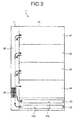
- Fig. 2 is a plane view illustrating the internal structure of the housing 31 of the bill change machine 11.
- the bill change machine 11 is equipped with an acquiring section 32 and a money dispensing section 33 in the housing 31.
- the bill change machine 11 is further equipped with an identification section 34, a storage section 35 and a conveyance section 36 inside the housing 31.
- the acquiring section 32 which includes the money depositing port 32a formed on the housing 31, acquires a paper such as a bill inserted through the money depositing port 32a into the housing 31.
- the money dispensing section 33 which includes the money dispensing port 33a formed on the housing 31, dispenses a paper such as a bill from money dispensing port 33a as change.
- the identification section 34 is arranged at a position close to the acquiring section 32 to determine authenticity and denomination of the bill on a conveyance belt to detect stain.
- the identification section 34 verifies whether or not the paper conveyed by the conveyance section 36 is a bill, and identifies its denomination if it is a genuine bill and then sums up the number of bills.
- the identification section 34 detects stain and wrinkles of the bill conveyed by the conveyance section 36.
- stain of bill the stain and wrinkles of bill are collectively referred to as "stain of bill”.
- stain of bill can be detected through a threshold value determination of an identification sensor 60 (refer to Fig. 3 ) of the identification section 34.
- a method for detecting the stain is described in a case in which the identification section 34 emits light to the bill and uses a sensor (light receiving element) for receiving a reflected light from the bill as the identification sensor 60.
- the surface of a bill having less stain and wrinkles easily reflects light but the surface of a bill having lots of stain and wrinkles hardly reflects light.
- the identification section 34 determines that the bill is stained. Further, the identification section 34 may carry out a threshold value determination with respect to an average value of the light receiving amount or a value obtained by executing some numerical operations for the light receiving amount.
- the threshold value may be stored in a storage device such as a ROM 52. Further, the threshold value may also be stored in a rewritable storage device, and the user can change (set) a detection level of the identification sensor 60 which determines the existence of stain through an operation from the operation key 38 (setting module). Then, the identification section 34 may detect stain of bill according to the set detection level.
- the storage section 35 is equipped with a first storage box 41, a second storage box 42, a third storage box 43 and a collection cassette 44.
- the first storage box 41 stores a paper identified by the identification section 34 as a first denomination bill (for example, 1000-yen bill).
- the second storage box 42 stores a paper identified by the identification section 34 as a second denomination bill (for example, 5000-yen bill).
- the third storage box 43 stores a paper identified by the identification section 34 as a third denomination bill (for example, 10000-yen bill). It is exemplified that the storage section 35 is provided with three storage boxes for respectively storing three kinds of denominations; however, the number of denominations to be handled and the number of the storage boxes are not limited to three and may be below two or above four.
- the collection cassette 44 is arranged detachably with respect to the housing 31 and is detached from the housing 31 after a lock mechanism (not shown) is released.
- the collection cassette 44 stores a bill transferred from the first storage box 41, the second storage box 42 or the third storage box 43 according to an instruction from the operation key 38.
- the collection cassette 44 is a storage box for collecting a bill stain on which is detected by the identification section 34 and temporarily storing the stained bill.
- a user such as a store manager having authority can detach the collection cassette 44 from the housing 31 and bring the collection cassette 44 from a register counter on which the POS terminal 2 is arranged to a place such as a back office of the store at which security is ensured while the stained bill is stored in the collection cassette 44.
- the conveyance section 36 functions as a money depositing conveyance module for conveying a bill from the money depositing port 32a to each storage box (the first storage box 41, the second storage box 42, the third storage box 43 and the collection cassette 44) of the storage section 35. Further, the conveyance section 36 functions as a money dispensing conveyance module for conveying a bill from each storage box (the first storage box 41, the second storage box 42 and the third storage box 43) for paying out of the storage section 35 to the money dispensing port 33a.
- the conveyance section 36 equipped with, for example, an endless conveyance belt, rotates the conveyance belt in a forward or reverse direction to convey the bill on the conveyance belt in a forward or reverse direction.
- the forward direction refers to a direction from the near side to the far side of the housing 31, i.e., a direction from the acquiring section 32 side to the first storage box 41 side.
- the reverse direction refers to a direction from the far side to the near side of the housing 31, i.e., a direction from the first storage box 41 side to the money dispensing section 33 side.
- the conveyance section 36 drives the conveyance belt in the forward direction to carry bill acquired in the housing 31 by the acquiring section 32 to each storage box (the first storage box 41, the second storage box 42, the third storage box 43 and the collection cassette 44) of the storage section 35.
- the conveyance section 36 drives the conveyance belt in the reverse direction to carry out bill for paying out from each storage box to the money dispensing port 33a.
- Each storage box for paying out refers to each storage box except the collection cassette 44, that is, the first storage box 41, the second storage box 42 and third storage box 43.
- the rotation direction of the conveyance belt is switched, and one conveyance belt is used for both a money depositing conveyance and a money dispensing conveyance; however, the embodiment is not limited to this.
- a belt for money depositing conveyance and a belt for money dispensing conveyance may be separately arranged as another constitution.
- Fig. 3 is block diagram illustrating an electrical connection of each section of the bill change machine 11.
- the bill change machine 11 includes a control section 51 constituted by a processor such as a CPU (Central Processing Unit) inside the housing 31.
- the control section 51 is connected with a ROM (Read Only Memory) 52 and a RAM (Random Access Memory) 53 through a bus line.
- ROM Read Only Memory
- RAM Random Access Memory
- the control section 51 is connected with each of a communication I/F (Interface) 54, a buzzer 55, a money depositing port sensor 56, a money depositing port motor 57, a money dispensing port motor 58, a money dispensing port sensor 59, the identification sensor 60, a storage box sensor 61, a storage box shutter 62, a collection cassette sensor 63 and conveyance motor 64 through a bus line and various interfaces. Further, the control section 51 is connected with the operation key 38 and the display device 39 (refer to Fig. 1 together) through a bus line and various interfaces.
- the control section 51 carries out an error notification processing to enable the buzzer 55 to output an error sound at the time an error occurs.
- the money depositing port sensor 56 arranged at the money depositing port 32a (refer to Fig. 2 ), detects the insertion of a bill into the money depositing port 32a.
- the money depositing port motor 57 if the bill is detected by the money depositing port sensor 56, drives a roller arranged at the money depositing port 32a to send out the bill inserted into the money depositing port 32a to the conveyance section 36.
- the money dispensing port motor 58 drives a roller arranged at the money dispensing port 33a (refer to Fig. 2 ) to send out the bill conveyed from the conveyance section 36 to the money dispensing section 33 to the outside of the money dispensing port 33a.
- the money dispensing port sensor 59 arranged at the money dispensing port 33a, detects whether or not the bill sent to the money dispensing port 33a is pulled out from the money dispensing port 33a.
- the identification sensor 60 is arranged at the identification section 34 (refer to Fig. 2 ).
- a light receiving sensor for receiving the reflected light from the bill as stated above can be used as the identification sensor 60.
- the storage box sensors 61 are respectively arranged at money depositing and dispensing ports of storage boxes of the storage section 35 (refer to Fig. 2 ), i.e., the first storage box 41, the second storage box 42, the third storage box 43 and the collection cassette 44.
- the storage box sensor 61 at the time of depositing money, sums up the number of the bills sent to each storage box (the first storage box 41, the second storage box 42, the third storage box 43 and the collection cassette 44) from the conveyance section 36.
- the storage box sensor 61 at the time of dispensing money, sums up the number of the bills sent to the conveyance section 36 from each storage box (the first storage box 41, the second storage box 42 and the third storage box 43) except the collection cassette 44.
- Each storage box shutter 62 is arranged at the money depositing and dispensing port of each storage box of the storage section 35 (refer to Fig. 2 ).
- the storage box shutter 62 of each storage box is opened when a bill is sent to the conveyance section 36 from each storage box and when a bill is carried into each storage box from the conveyance section 36, and is capable of sending out/carrying the bill.
- the collection cassette sensor 63 is arranged on the inner wall surface of a storage frame section that stores the collection cassette 44 in the storage section 35 (refer to Fig. 2 ). The collection cassette sensor 63 detects that the collection cassette 44 is housed in the storage section 35 or is detached from the housing (storage section 35).
- the conveyance motor 64 arranged at the conveyance section 36 (refer to Fig. 2 ), enables the conveyance belt of the conveyance section 36 to rotate in either the forward direction or the reverse direction.
- the operation key 38 receives a money dispensing instruction, an error releasing instruction and various setting operations.
- the display device 39 (refer to Fig. 1 ) displays various kinds of information such as a total balance amount stored in the storage section 35, a number of stored bills (a number of remaining bills) in each denomination, an error message, a money depositing amount and a money dispensing amount.
- the ROM 52 stores various programs executed by the control section 51 and various data.
- the RAM 53 temporarily stores programs and data when the control section 51 executes various programs.
- the control section 51 collectively controls each section of the bill change machine 11 by reading out the program stored in the ROM 52 to the RAM 53 to execute it.
- the programs executed by the bill change machine 11 are incorporated in the ROM 52 in advance to be provided.
- the programs executed by the bill change machine 11 may be recorded in a computer-readable recording medium such as a CD-ROM, a FD (Flexible Disk), a CD-R, a DVD (Digital Versatile Disk) in the form of an installable or executable file to be provided.
- a computer-readable recording medium such as a CD-ROM, a FD (Flexible Disk), a CD-R, a DVD (Digital Versatile Disk) in the form of an installable or executable file to be provided.
- the programs executed by the bill change machine 11 may be stored in a computer connected with a network such as an Internet and downloaded via the network to be provided.
- the programs executed by the bill change machine 11 may be provided or distributed via the network such as the Internet.
- the programs executed by the bill change machine 11 functions as each section (a money dispensing instruction output section 81 and a conveyance control section 82) and, as in the actual hardware, each section is generated on the main storage device through the execution of the programs read from the ROM 52 by the CPU (processor).
- the money dispensing instruction output section 81 receives a money dispensing instruction notified from a control section 71 of the POS terminal 2.
- the POS terminal 2 notifies, for example, the bill change machine 11 of the amount paid by bills within the change amount as the money dispensing instruction.
- the money dispensing instruction output section 81 receives the money dispensing instruction even when the money dispensing amount is input from the operation key 38.
- the money dispensing instruction output section 81 determines the amount of dispensed money of each denomination according to the money dispensing total amount and outputs the determined amount of dispensed money to the storage box of each denomination (the first storage box 41, the second storage box 42 and the third storage box 43).
- the conveyance control section 82 collectively controls the operation of each mechanism of the conveyance section 36.
- the conveyance control section 82 controls the driving of the conveyance motor 64 to enable the conveyance belt of the conveyance section 36 to rotate in a forward or reverse direction. In this way, the conveyance control section 82 switches the conveyance direction of the bill at the time of depositing or dispensing money.
- the conveyance control section 82 controls the conveyance section 36 to discharge a bill identified as a counterfeit bill by the identification section 34 from the money dispensing port 33a as a reject bill.
- the conveyance control section 82 controls the conveyance section 36 to convey a bill identified as a genuine bill by the identification section 34 to one of the storage boxes of the storage section 35 based on the identification result of the identification section 34.
- the conveyance section 36 carries the bill with stain determined by the identification section 34 to the collection cassette 44 to collect it so that the bill with stain is not used for paying out.
- the conveyance section 36 carries a bill with less stain determined by the identification section 34 to one of the first storage box 41, the second storage box 42 and the third storage box 43 by denominations. That is, the conveyance section 36 carries the bill identified as a first denomination by the identification section 34 to the first storage box 41. The conveyance section 36 carries the bill identified as a second denomination by the identification section 34 to the second storage box 42. The conveyance section 36 carries the bill identified as a third denomination by the identification section 34 to the third storage box 43.
- the conveyance control section 82 controls the conveyance section 36 to move bills having denomination and number thereof instructed from the first storage box 41, the second storage box 42 and the third storage box 43 into the collection cassette 44 according to a collection instruction received through the operation key 38.
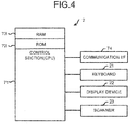
- Fig. 4 is a block diagram illustrating the functional structure of the POS terminal 2.
- the POS terminal 2 is equipped with a control section 71, a ROM 72 and a RAM 73.
- the ROM 72 stores various programs executed by the control section 71 and various data.
- the RAM 73 temporarily stores data and programs executed by the control section 71.
- a processor such as a CPU is used as the control section 71.
- the control section 71 collectively controls each section of the POS terminal 2 through reading out the program stored in the ROM 72 to the RAM 73 to execute it.
- control section 71 is connected with the communication I/F 74 via a bus line.
- the communication I/F 74 is an interface for transmitting/receiving data to/from the change machine 1.
- the control section 71 is connected with I/O devices such as the keyboard 21 (refer to Fig. 1 ), the display device 22 (refer to Fig. 1 ) and the scanner 23 via the bus line.
- the scanner 23 reads a commodity code attached to each commodity in the form of a barcode or a two-dimension code.
- the control section 71 inquires, if the scanner 23 reads the commodity code, the read commodity code of a commodity master file to read commodity information (such as unit price) of the commodity specified with the commodity code.
- the commodity master file may be stored in a store server connected with the POS terminal 2 through a connection circuit such as a LAN (Local Area Network).
- the control section 71 may inquire the commodity information of the commodity master file via a connection circuit.
- the control section 71 downloads the commodity master file from the store server to store it in the POS terminal 2 and may inquire the commodity information of the commodity master file serving as a storage destination.
- the control section 71 calculates a total amount of one transaction, according to the unit price and the sales quantity of each commodity, to carry out a settlement processing. Further, the control section 71 generates sales data of the transaction with the use of the commodity information of the transaction content and the information such as a price, quantity, total amount, deposited amount and change amount. Then, the control section 71 sends the sales data to the store server at a specific timing and registers the sales data in a sales master file managed by the store server.
- the control section 71 of the POS terminal 2 displays the total amount of one transaction on the display device 22.
- the customer refers to the displayed amount to pay the total amount in cash to the store clerk.
- the store clerk inserts the bills in the payment (cash) received from the customer into the money depositing port 32a of the bill change machine 11.
- the store clerk also puts the coins in the payment received from the customer into the money depositing port 46a of the coin change machine 12.
- the bills inserted into the money depositing port 32a are acquired by the conveyance section 36 inside the housing 31 with the money depositing port motor 57, and an authenticity determination, a denomination identification and a stain detection are carried out for the bills by the identification section 34.
- the conveyance control section 82 collects the bill with stain determined by the identification section 34 to the collection cassette 44 through the conveyance section 36.
- the conveyance control section 82 through the conveyance section 36, stores the bill with less stain determined by the identification section 34 in one of the first storage box 41, the second storage box 42 and the third storage box 43 in correspondence to the denomination identified by the identification section 34.
- the bill change machine 11 and the coin change machine 12 respectively calculate bill depositing amount and coin depositing amount and individually notify the calculated amount to the POS terminal 2.
- the bill change machine 11 calculates the bill depositing amount on the basis of the denomination and the number of bills identified by the identification section 34. At this time, the bill change machine 11 also calculates, even for the bill, of which stain is detected, collected in the collection cassette 44, the bill depositing amount thereof as a depositing bill and includes its denomination and number of bills to all the bill depositing amount.
- the control section 71 of the POS terminal 2 subtracts the total amount of commodity prices from a total of the notified bill depositing amount and the notified coin depositing amount to calculate the change amount. Then, the control section 71 of the POS terminal 2 notifies the bill change machine 11 of the amount of bills within the change amount, paid to the customer, which is contained in the money dispensing instruction. Further, the control section 71 also notifies the coin change machine 12 of the amount of coins, paid to the customer, which is contained in the money dispensing instruction. The control section 71 prints a receipt through a printer.
- the coin change machine 12 dispenses coins of the notified dispensing amount according to the money dispensing instruction from the POS terminal 2.
- the bill change machine 11 also dispenses bills of the notified dispensing amount according to the money dispensing instruction from the POS terminal 2.
- the store clerk hands over the bills and coins dispensed as change and a receipt to the customer. In this way, the settlement of one transaction is completed.
- the bill change machine 11 carries the bills of which no stain is detected to the storage section 35 which stores bills for paying out, and collects the bills of which stain is detected in the collection cassette 44. In this way, the bill with stain is treated as a depositing bill but is not paid to a customer as change. Thus, it can save the troublesome operation in which the store clerk removes the bill with stain and changes to the bill with no stain to hand over it to the customer, and thus the enhancement of the service quality is achieved without any troublesome operation.
- the bill change machine 11 treats the bill with stain as a depositing bill without rejecting (sending back) the bill with stain to calculate the bill depositing amount.
- the store collects the bill with stain but not hands over it to the customer, and thus the customer does not feel inconvenience.
- the bill change machine 11 identifies a bill with stain and collects it immediately after depositing the bill, and thus a bill can directly be conveyed from the storage box to the money dispensing port 33a, as similar to the conventional money dispensing processing. Further, the time required until the store clerk hands over the change to the customer can be almost the same extent to that in the conventional processing.
- the bill having stain is detected and collected at the time of depositing the bill; however, the timing of collecting the bill having stain is not limited to this. As another example, the bill having stain may be detected and collected at the time of dispensing the bill.
- the first storage box 41, the second storage box 42 and the third storage box 43 send out the bills of each denomination to the conveyance section 36 according to the money dispensing instruction from the money dispensing instruction output section 81.
- the conveyance control section 82 enables the conveyance motor 64 to rotate in reverse direction to drive the conveyance belt in the reverse direction, and conveys the bills sent out from each storage box one by one to a position where the identification section 34 is arranged.
- the bill of which stain less than a specified degree is detected by the identification section 34 is conveyed to the money dispensing port 33a by the conveyance section 36, and is sent to the money dispensing port 33a through the cooperation with the money dispensing port motor 58.
- the conveyance control section 82 controls the conveyance section 36 to send the bill of which stain more than the specified level is detected by the identification section 34 to the collection cassette 44 without feeding the bill having much stain to the money dispensing port 33a. Then, the identification section 34 notifies the money dispensing instruction output section 81 of the denomination of the bill of which much stain is detected.
- the storage box sensor 61 arranged in the collection cassette 44 notifies the money dispensing instruction output section 81 of the number of the collected bills.
- the money dispensing instruction output section 81 newly outputs the money dispensing instruction containing the denomination and the number of the bills notified.
- the storage box of each denomination (the first storage box 41, the second storage box 42 and the third storage box 43) and the conveyance section 36 dispense the bills corresponding to the collected bills again.
- the bill change machine 11 controls to compensate the amount corresponding to collected bills to dispense all the original change amounts.
- one collection cassette 44 is arranged in the storage section 35, and the bills having much stain are collected in the collection cassette 44 regardless of its denomination; however, a plurality of the collection sections may be arranged by each denomination to separately collect bills by each denomination.
- Fig. 2 it is exemplified that the collection cassette 44 is arranged at the front or near side of the storage section 35 but the collection cassette 44 may be arranged at the rear or far side of the storage section 35, for example, at the rear side of the first storage box 41.
- a coin having much stain may be detected and collected by the coin change machine 12.
- the stain of coin may be detected with the use of the light receiving sensor as being similar to that described above or another sensor such as a material sensor.
- the collection section for collecting coin having much stain may use a drawer box arranged at the lower portion of a coin conveyance route (for example, refer to the structure recorded in Japanese Unexamined Patent Application Publication No. 5620442 ).
- a shutter arranged at the conveyance route is opened and the coin having much stain that is being conveyed falls in the drawer box arranged at the lower portion of the conveyance route.
- the coil having stain can be collected in the collection section without being stored in the storage section. Therefore, the coin having much stain cannot be accidentally dispensed as change.
- the cash processing apparatus of the present invention is applied to the change machine 1 (the bill change machine 11 or the coin change machine 12) connected with the POS terminal 2; however, the embodiment is not limited to this.
- a money depositing/dispensing device arranged in an ATM Automated Teller Machine
- the foregoing structure may be applied to a cash processing apparatus for carrying out either of depositing money and dispensing money.
- the present invention described above may be applied to an apparatus equipped with both the functional structure of the change machine 1 and the functional structure of the POS terminal 2.
- a self-checkout apparatus hereinafter, simply referred to as a "self-POS terminal" used in a store such as a supermarket and a convenience store can be utilized.
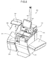
- Fig. 5 is an external perspective view illustrating the schematic structure of a self-POS terminal 200 according to another embodiment.
- a main body 202 of the self-POS terminal 200 is equipped with a display device 106 arranged at the surface of a touch panel 105 and a commodity reading section 110 for capturing a commodity image to recognize (detect) the category of a commodity.
- a liquid crystal display device is used as the display device 106, for example.
- the display device 106 displays a guidance screen for notifying a customer of the operation method of the self-POS terminal 200, various input screens, a registration screen for displaying information of the commodity captured by the commodity reading section 110 and a settlement screen for displaying total amount and deposited amount of the commodity to select a payment method.
- the commodity reading section 110 reads the commodity image through an image capturing section arranged inside the reading window 103 while the customer holds a code symbol attached to the commodity over the reading window 103 of the commodity reading section 110.
- a commodity placing table 203 for placing unsettled commodities input in a basket is arranged at the right side of the main body 202.
- a commodity placing table 204 for placing settled commodities is arranged at the left side of the main body 202.
- a temporary placing table 206 for temporarily placing settled but not bagged commodities is arranged at the upper surface of the commodity placing table 204 in a protruding manner.
- a pair of bag hooks 205 for hooking bags in which the settled commodities are put is arranged at the near side end part of the temporary placing table 206.
- the commodity placing tables 203 and 204 both include a weighing scale which has a function of confirming whether or not the weight of the commodity before the settlement is the same as that after the settlement.
- a change machine 201 is arranged in the main body 202 of the self-POS terminal 200 to deposit the bill for settlement and receive the change bill.
- the functional structure of the foregoing change machine 1 (refer to Fig. 1 to Fig. 3 ) may be applied to the change machine 201.
- the functional structure of the foregoing POS terminal 2 (refer to Fig. 1 and Fig. 5 ) may be applied to the self-POS terminal 200.
- the cash processing apparatus (as an example, change machine 1) of the present embodiment collects the money of which much stain is detected in the collection section without paying out the money having much stain to the money dispensing port.
- the cash processing apparatus can be provided that does not dispense the stained money.
Abstract
Description
- Embodiments described herein relate generally to a cash processing apparatus and a system relating thereto.
- Conventionally, a cash processing apparatus is known which is used together with an electronic equipment, such as a POS (Point Of Sales) terminal and an ECR (Electronic Cash Register), connected therewith. Such a cash processing apparatus selects money input from an input port by denominations, stores the selected money in a storage section and dispenses money stored in the storage section in response to a money dispensing instruction from the POS terminal. In such a cash processing apparatus, even if money with no stain is prepared in the storage section beforehand at a store side, if money having stain is received from a customer, money having much stain is dispensed as a change.
- In a conventional technology, there is a cash processing apparatus which does not receive such seriously stained money that causes difficulty of identification in the denomination thereof and discharges the money with much stain from a reject section. However, there is also money that has no stain enough to be rejected and the denomination thereof can be identified, but is undesirable for the store to be dispensed to a customer as a change. In such a store, the store clerk removes the money having much stain when delivering a change to the customer and delivers money with less train selected by himself/herself to the customer. There are problems in which the customer has to wait for if a job of selecting money is added at the time of settlement and the determination standard in selecting money depends on store clerks.
- To this end, there is provided a cash processing apparatus, comprising:
- a storage section configured to store money by denominations for paying out;
- a money depositing conveyance module configured to convey money from a money depositing port to the storage section;
- a money dispensing conveyance module configured to convey money from the storage section to a money dispensing port; and
- an identification module configured to identify the denomination of the money conveyed by the money depositing conveyance module and also to detect stain of the money, wherein
- the money depositing conveyance module collects the money of which stain is detected by the identification module to a collection section, and conveys the money of which no stain is detected by the identification module to the storage section by individual denominations.
- Preferably, the collection section includes a collection box arranged detachably with respect to the collection section.
- Preferably still, the cash processing apparatus further comprises a setting module configured to set a detection level which is used by the identification module at the time of detecting stain of the money, wherein the identification module detects stain of the money according to the detection level set by the setting module.
- Preferably yet, the cash processing apparatus further comprises a calculation module configured to calculate the amount of the money collected in the collection section by the money depositing conveyance module.
- Suitably, the identification module includes a sensor for receiving a light reflected from the money to detect stain of the money according to the receiving amount of the light reflected from the money.
- Typically, the cash processing apparatus may comprise:
- a storage section configured to store money by denominations for paying out;
- a money dispensing conveyance module configured to convey money from the storage section to a money dispensing port;
- a money dispensing instruction module configured to instruct the denomination and the amount of the money to be paid out from the money dispensing port;
- a paying out module configured to pay out money of the instructed amount from the storage section according to the instruction of the money dispensing instruction module;
- a detection module configured to detect stain of the money conveyed by the money dispensing conveyance module;
- a collection module configured to collect the money of which stain is detected by the detection module in a collection section without paying out it to the money dispensing port, and also to calculate the denomination and the amount of the collected money; and
- an additional payout module configured to again pay out money corresponding to the collected money by the collection module.
- The invention also relates to a cash processing system, comprising:
- a storage means configured to store money by denominations for paying out;
- a money depositing conveyance means configured to convey money from a money depositing means to the storage means;
- a money dispensing conveyance means configured to convey money from the storage means to a money dispensing means; and
- an identification means configured to identify the denomination of the money conveyed by the money depositing conveyance means and also to detect stain of the money, wherein
- the money depositing conveyance means collects the money of which stain is detected by the identification means to a collection means, and conveys the money of which no stain is detected by the identification means to the storage means by individual denominations.
- Conveniently, the collection means includes a collection box arranged detachably with respect to the collection means.
- Conveniently still, the cash processing system further comprises a setting means configured to set a detection level which is used by the identification means at the time of detecting stain of the money, wherein the identification means detects stain of the money according to the detection level set by the setting means.
- Conveniently yet, the cash processing apparatus further comprises a calculation module configured to calculate the amount of the money collected in the collection section by the money depositing conveyance module.
- Preferably, the identification module includes a sensor for receiving a light reflected from the money to detect stain of the money according to the receiving amount of the light reflected from the money.
- Typically, the cash processing system may comprise:
- a storage means configured to store money by denominations for paying out;
- a money dispensing conveyance means configured to convey money from the storage means to a money dispensing means;
- a money dispensing instruction means configured to instruct the denomination and the amount of the money to be paid out from the money dispensing means;
- a paying out means configured to pay out money of the instructed amount from the storage means according to the instruction of the money dispensing instruction means;
- a detection means configured to detect stain of the money conveyed by the money dispensing conveyance means;
- a collection means configured to collect the money of which stain is detected by the detection means in a collection means without paying out it to the money dispensing means, and also to calculate the denomination and the amount of the collected money; and
- an additional payout means configured to again pay out money corresponding to the collected money by the collection means.
- The above and other objects, features and advantages of the present invention will be made apparent from the following description of the preferred embodiments, given as non-limiting examples, with reference to the accompanying drawings, in which:
-
Fig. 1 is a perspective view illustrating appearances of a change machine and a POS terminal according to an embodiment; -
Fig. 2 is a plane view schematically illustrating the inside of a bill change machine; -
Fig. 3 is a block diagram illustrating an electrical connection of each section of the bill change machine; -
Fig. 4 is a block diagram illustrating the functional structure of the POS terminal; and -
Fig. 5 is an external perspective view illustrating the schematic structure of a self-POS terminal according to another embodiment. - A cash processing apparatus includes a storage section, a money depositing conveyance module, a money dispensing conveyance module and an identification module. The storage section stores money by denominations for paying out. The money depositing conveyance module conveys money from a money depositing port to the storage section. The money dispensing conveyance module conveys money from the storage section to a money dispensing port. The identification module identifies the denomination of the money conveyed by the money depositing conveyance module and also detects stain of the money. The money depositing conveyance module collects the money of which stain is detected by the identification module to a collection section, and conveys the money of which no stain is detected by the identification module to the storage section by individual denominations.
- The above-defined apparatus may be applied in a system comprising the corresponding means, as defined in claims 7 to 12.
-
Fig. 1 is a perspective view illustrating appearances of a change machine 1 and aPOS terminal 2. In general, a plurality ofPOS terminals 2 each of which is assigned with a unique register number and arranged at a settlement area is arranged in a store. A cashier or store clerk uses thePOS terminal 2 to carry out a sales processing. ThePOS terminal 2 is equipped with akeyboard 21, adisplay device 22 and a scanner 23 (refer toFig. 4 ). - The change machine 1 includes a
bill change machine 11 and acoin change machine 12. Thebill change machine 11 identifies a bill to store it therein and dispenses the stored bill as change. Thecoin change machine 12 identifies a coin to store it therein and dispenses the stored coin as change. - The
bill change machine 11 having ahousing 31 is equipped with amoney depositing port 32a and amoney dispensing port 33a at the near side end part of the upper surface of thehousing 31. Further, anoperation key 38 and adisplay device 39 are arranged on the upper surface of thehousing 31 at the far side of themoney dispensing port 33a - The
coin change machine 12 having ahousing 51 is equipped with amoney depositing port 46a through which a plurality of coins can be collectively put at the right-near end part of the upper surface of thehousing 51. Further, thecoin change machine 12 is also equipped with amoney dispensing port 47a at the left-near end part of thehousing 51 for dispensing coins from thecoin change machine 12. Anoperation key 48 and adisplay device 49 are arranged on the upper surface of thehousing 51. - Next, the structure of the
bill change machine 11 is described in detail. - In a store that intends to improve its service quality, there is a need to arrange bills having less stain and wrinkles to hand over them to a customer. Hereinafter, an example is adopted to describe that the
bill change machine 11 identifies bills having lots of stain and wrinkles to collect them. -
Fig. 2 is a plane view illustrating the internal structure of thehousing 31 of thebill change machine 11. Thebill change machine 11 is equipped with an acquiring section 32 and amoney dispensing section 33 in thehousing 31. Thebill change machine 11 is further equipped with anidentification section 34, astorage section 35 and aconveyance section 36 inside thehousing 31. - The acquiring section 32, which includes the
money depositing port 32a formed on thehousing 31, acquires a paper such as a bill inserted through themoney depositing port 32a into thehousing 31. Themoney dispensing section 33, which includes themoney dispensing port 33a formed on thehousing 31, dispenses a paper such as a bill frommoney dispensing port 33a as change. - The
identification section 34 is arranged at a position close to the acquiring section 32 to determine authenticity and denomination of the bill on a conveyance belt to detect stain. Theidentification section 34 verifies whether or not the paper conveyed by theconveyance section 36 is a bill, and identifies its denomination if it is a genuine bill and then sums up the number of bills. Theidentification section 34 detects stain and wrinkles of the bill conveyed by theconveyance section 36. Hereinafter, the stain and wrinkles of bill are collectively referred to as "stain of bill". - No specific limitation is given to the method for detecting the stain, as an example, stain of bill can be detected through a threshold value determination of an identification sensor 60 (refer to
Fig. 3 ) of theidentification section 34. For example, a method for detecting the stain is described in a case in which theidentification section 34 emits light to the bill and uses a sensor (light receiving element) for receiving a reflected light from the bill as theidentification sensor 60. In general, there is a tendency that the surface of a bill having less stain and wrinkles easily reflects light but the surface of a bill having lots of stain and wrinkles hardly reflects light. Thus, if the light receiving amount of reflected light from a bill is smaller than a specific threshold value, theidentification section 34 determines that the bill is stained. Further, theidentification section 34 may carry out a threshold value determination with respect to an average value of the light receiving amount or a value obtained by executing some numerical operations for the light receiving amount. - The threshold value may be stored in a storage device such as a
ROM 52. Further, the threshold value may also be stored in a rewritable storage device, and the user can change (set) a detection level of theidentification sensor 60 which determines the existence of stain through an operation from the operation key 38 (setting module). Then, theidentification section 34 may detect stain of bill according to the set detection level. - The
storage section 35 is equipped with afirst storage box 41, asecond storage box 42, athird storage box 43 and acollection cassette 44. Thefirst storage box 41 stores a paper identified by theidentification section 34 as a first denomination bill (for example, 1000-yen bill). Thesecond storage box 42 stores a paper identified by theidentification section 34 as a second denomination bill (for example, 5000-yen bill). Thethird storage box 43 stores a paper identified by theidentification section 34 as a third denomination bill (for example, 10000-yen bill). It is exemplified that thestorage section 35 is provided with three storage boxes for respectively storing three kinds of denominations; however, the number of denominations to be handled and the number of the storage boxes are not limited to three and may be below two or above four. - The
collection cassette 44 is arranged detachably with respect to thehousing 31 and is detached from thehousing 31 after a lock mechanism (not shown) is released. Thecollection cassette 44 stores a bill transferred from thefirst storage box 41, thesecond storage box 42 or thethird storage box 43 according to an instruction from theoperation key 38. Further, thecollection cassette 44 is a storage box for collecting a bill stain on which is detected by theidentification section 34 and temporarily storing the stained bill. A user such as a store manager having authority can detach thecollection cassette 44 from thehousing 31 and bring thecollection cassette 44 from a register counter on which thePOS terminal 2 is arranged to a place such as a back office of the store at which security is ensured while the stained bill is stored in thecollection cassette 44. - The
conveyance section 36 functions as a money depositing conveyance module for conveying a bill from themoney depositing port 32a to each storage box (thefirst storage box 41, thesecond storage box 42, thethird storage box 43 and the collection cassette 44) of thestorage section 35. Further, theconveyance section 36 functions as a money dispensing conveyance module for conveying a bill from each storage box (thefirst storage box 41, thesecond storage box 42 and the third storage box 43) for paying out of thestorage section 35 to themoney dispensing port 33a. - The
conveyance section 36 equipped with, for example, an endless conveyance belt, rotates the conveyance belt in a forward or reverse direction to convey the bill on the conveyance belt in a forward or reverse direction. The forward direction refers to a direction from the near side to the far side of thehousing 31, i.e., a direction from the acquiring section 32 side to thefirst storage box 41 side. The reverse direction refers to a direction from the far side to the near side of thehousing 31, i.e., a direction from thefirst storage box 41 side to themoney dispensing section 33 side. - At the time of depositing money, the
conveyance section 36 drives the conveyance belt in the forward direction to carry bill acquired in thehousing 31 by the acquiring section 32 to each storage box (thefirst storage box 41, thesecond storage box 42, thethird storage box 43 and the collection cassette 44) of thestorage section 35. - At the time of dispensing money, the
conveyance section 36 drives the conveyance belt in the reverse direction to carry out bill for paying out from each storage box to themoney dispensing port 33a. Each storage box for paying out refers to each storage box except thecollection cassette 44, that is, thefirst storage box 41, thesecond storage box 42 andthird storage box 43. - Further, at the time of depositing and dispensing money, the rotation direction of the conveyance belt is switched, and one conveyance belt is used for both a money depositing conveyance and a money dispensing conveyance; however, the embodiment is not limited to this. A belt for money depositing conveyance and a belt for money dispensing conveyance may be separately arranged as another constitution.
-
Fig. 3 is block diagram illustrating an electrical connection of each section of thebill change machine 11. Thebill change machine 11 includes acontrol section 51 constituted by a processor such as a CPU (Central Processing Unit) inside thehousing 31. Thecontrol section 51 is connected with a ROM (Read Only Memory) 52 and a RAM (Random Access Memory) 53 through a bus line. - The
control section 51 is connected with each of a communication I/F (Interface) 54, abuzzer 55, a money depositingport sensor 56, a money depositingport motor 57, a money dispensingport motor 58, a money dispensingport sensor 59, theidentification sensor 60, astorage box sensor 61, astorage box shutter 62, acollection cassette sensor 63 andconveyance motor 64 through a bus line and various interfaces. Further, thecontrol section 51 is connected with theoperation key 38 and the display device 39 (refer toFig. 1 together) through a bus line and various interfaces. - The
control section 51 carries out an error notification processing to enable thebuzzer 55 to output an error sound at the time an error occurs. The money depositingport sensor 56, arranged at themoney depositing port 32a (refer toFig. 2 ), detects the insertion of a bill into themoney depositing port 32a. The money depositingport motor 57, if the bill is detected by the money depositingport sensor 56, drives a roller arranged at themoney depositing port 32a to send out the bill inserted into themoney depositing port 32a to theconveyance section 36. - The money dispensing
port motor 58 drives a roller arranged at themoney dispensing port 33a (refer toFig. 2 ) to send out the bill conveyed from theconveyance section 36 to themoney dispensing section 33 to the outside of themoney dispensing port 33a. The money dispensingport sensor 59, arranged at themoney dispensing port 33a, detects whether or not the bill sent to themoney dispensing port 33a is pulled out from themoney dispensing port 33a. - The
identification sensor 60 is arranged at the identification section 34 (refer toFig. 2 ). For example, a light receiving sensor for receiving the reflected light from the bill as stated above can be used as theidentification sensor 60. - The
storage box sensors 61 are respectively arranged at money depositing and dispensing ports of storage boxes of the storage section 35 (refer toFig. 2 ), i.e., thefirst storage box 41, thesecond storage box 42, thethird storage box 43 and thecollection cassette 44. Thestorage box sensor 61, at the time of depositing money, sums up the number of the bills sent to each storage box (thefirst storage box 41, thesecond storage box 42, thethird storage box 43 and the collection cassette 44) from theconveyance section 36. Moreover, thestorage box sensor 61, at the time of dispensing money, sums up the number of the bills sent to theconveyance section 36 from each storage box (thefirst storage box 41, thesecond storage box 42 and the third storage box 43) except thecollection cassette 44. - Each
storage box shutter 62 is arranged at the money depositing and dispensing port of each storage box of the storage section 35 (refer toFig. 2 ). Thestorage box shutter 62 of each storage box is opened when a bill is sent to theconveyance section 36 from each storage box and when a bill is carried into each storage box from theconveyance section 36, and is capable of sending out/carrying the bill. - The
collection cassette sensor 63 is arranged on the inner wall surface of a storage frame section that stores thecollection cassette 44 in the storage section 35 (refer toFig. 2 ). Thecollection cassette sensor 63 detects that thecollection cassette 44 is housed in thestorage section 35 or is detached from the housing (storage section 35). - The
conveyance motor 64, arranged at the conveyance section 36 (refer toFig. 2 ), enables the conveyance belt of theconveyance section 36 to rotate in either the forward direction or the reverse direction. - The operation key 38 (refer to
Fig. 1 ) receives a money dispensing instruction, an error releasing instruction and various setting operations. The display device 39 (refer toFig. 1 ) displays various kinds of information such as a total balance amount stored in thestorage section 35, a number of stored bills (a number of remaining bills) in each denomination, an error message, a money depositing amount and a money dispensing amount. - The
ROM 52 stores various programs executed by thecontrol section 51 and various data. TheRAM 53 temporarily stores programs and data when thecontrol section 51 executes various programs. Thecontrol section 51 collectively controls each section of thebill change machine 11 by reading out the program stored in theROM 52 to theRAM 53 to execute it. - The programs executed by the
bill change machine 11 are incorporated in theROM 52 in advance to be provided. The programs executed by thebill change machine 11 may be recorded in a computer-readable recording medium such as a CD-ROM, a FD (Flexible Disk), a CD-R, a DVD (Digital Versatile Disk) in the form of an installable or executable file to be provided. - Furthermore, the programs executed by the
bill change machine 11 may be stored in a computer connected with a network such as an Internet and downloaded via the network to be provided. The programs executed by thebill change machine 11 may be provided or distributed via the network such as the Internet. - The programs executed by the
bill change machine 11 functions as each section (a money dispensinginstruction output section 81 and a conveyance control section 82) and, as in the actual hardware, each section is generated on the main storage device through the execution of the programs read from theROM 52 by the CPU (processor). - The money dispensing
instruction output section 81 receives a money dispensing instruction notified from acontrol section 71 of thePOS terminal 2. ThePOS terminal 2 notifies, for example, thebill change machine 11 of the amount paid by bills within the change amount as the money dispensing instruction. The money dispensinginstruction output section 81 receives the money dispensing instruction even when the money dispensing amount is input from theoperation key 38. The money dispensinginstruction output section 81 determines the amount of dispensed money of each denomination according to the money dispensing total amount and outputs the determined amount of dispensed money to the storage box of each denomination (thefirst storage box 41, thesecond storage box 42 and the third storage box 43). - The
conveyance control section 82 collectively controls the operation of each mechanism of theconveyance section 36. For example, theconveyance control section 82 controls the driving of theconveyance motor 64 to enable the conveyance belt of theconveyance section 36 to rotate in a forward or reverse direction. In this way, theconveyance control section 82 switches the conveyance direction of the bill at the time of depositing or dispensing money. - The
conveyance control section 82 controls theconveyance section 36 to discharge a bill identified as a counterfeit bill by theidentification section 34 from themoney dispensing port 33a as a reject bill. Theconveyance control section 82 controls theconveyance section 36 to convey a bill identified as a genuine bill by theidentification section 34 to one of the storage boxes of thestorage section 35 based on the identification result of theidentification section 34. - More specifically, the
conveyance section 36 carries the bill with stain determined by theidentification section 34 to thecollection cassette 44 to collect it so that the bill with stain is not used for paying out. - Further, the
conveyance section 36 carries a bill with less stain determined by theidentification section 34 to one of thefirst storage box 41, thesecond storage box 42 and thethird storage box 43 by denominations. That is, theconveyance section 36 carries the bill identified as a first denomination by theidentification section 34 to thefirst storage box 41. Theconveyance section 36 carries the bill identified as a second denomination by theidentification section 34 to thesecond storage box 42. Theconveyance section 36 carries the bill identified as a third denomination by theidentification section 34 to thethird storage box 43. - The
conveyance control section 82 controls theconveyance section 36 to move bills having denomination and number thereof instructed from thefirst storage box 41, thesecond storage box 42 and thethird storage box 43 into thecollection cassette 44 according to a collection instruction received through theoperation key 38. -
Fig. 4 is a block diagram illustrating the functional structure of thePOS terminal 2. ThePOS terminal 2 is equipped with acontrol section 71, aROM 72 and aRAM 73. TheROM 72 stores various programs executed by thecontrol section 71 and various data. TheRAM 73 temporarily stores data and programs executed by thecontrol section 71. A processor such as a CPU is used as thecontrol section 71. Thecontrol section 71 collectively controls each section of thePOS terminal 2 through reading out the program stored in theROM 72 to theRAM 73 to execute it. - Further, the
control section 71 is connected with the communication I/F 74 via a bus line. The communication I/F 74 is an interface for transmitting/receiving data to/from the change machine 1. Thecontrol section 71 is connected with I/O devices such as the keyboard 21 (refer toFig. 1 ), the display device 22 (refer toFig. 1 ) and thescanner 23 via the bus line. Thescanner 23 reads a commodity code attached to each commodity in the form of a barcode or a two-dimension code. - The
control section 71 inquires, if thescanner 23 reads the commodity code, the read commodity code of a commodity master file to read commodity information (such as unit price) of the commodity specified with the commodity code. The commodity master file may be stored in a store server connected with thePOS terminal 2 through a connection circuit such as a LAN (Local Area Network). Moreover, thecontrol section 71 may inquire the commodity information of the commodity master file via a connection circuit. Alternatively, thecontrol section 71 downloads the commodity master file from the store server to store it in thePOS terminal 2 and may inquire the commodity information of the commodity master file serving as a storage destination. - The
control section 71 calculates a total amount of one transaction, according to the unit price and the sales quantity of each commodity, to carry out a settlement processing. Further, thecontrol section 71 generates sales data of the transaction with the use of the commodity information of the transaction content and the information such as a price, quantity, total amount, deposited amount and change amount. Then, thecontrol section 71 sends the sales data to the store server at a specific timing and registers the sales data in a sales master file managed by the store server. - Next, the settlement processing carried out through the cooperation of the
POS terminal 2 with the change machine 1 is described. Thecontrol section 71 of thePOS terminal 2 displays the total amount of one transaction on thedisplay device 22. The customer refers to the displayed amount to pay the total amount in cash to the store clerk. The store clerk inserts the bills in the payment (cash) received from the customer into themoney depositing port 32a of thebill change machine 11. The store clerk also puts the coins in the payment received from the customer into themoney depositing port 46a of thecoin change machine 12. The bills inserted into themoney depositing port 32a are acquired by theconveyance section 36 inside thehousing 31 with the money depositingport motor 57, and an authenticity determination, a denomination identification and a stain detection are carried out for the bills by theidentification section 34. - The
conveyance control section 82 collects the bill with stain determined by theidentification section 34 to thecollection cassette 44 through theconveyance section 36. Theconveyance control section 82, through theconveyance section 36, stores the bill with less stain determined by theidentification section 34 in one of thefirst storage box 41, thesecond storage box 42 and thethird storage box 43 in correspondence to the denomination identified by theidentification section 34. - The
bill change machine 11 and thecoin change machine 12 respectively calculate bill depositing amount and coin depositing amount and individually notify the calculated amount to thePOS terminal 2. Thebill change machine 11 calculates the bill depositing amount on the basis of the denomination and the number of bills identified by theidentification section 34. At this time, thebill change machine 11 also calculates, even for the bill, of which stain is detected, collected in thecollection cassette 44, the bill depositing amount thereof as a depositing bill and includes its denomination and number of bills to all the bill depositing amount. - The
control section 71 of thePOS terminal 2 subtracts the total amount of commodity prices from a total of the notified bill depositing amount and the notified coin depositing amount to calculate the change amount. Then, thecontrol section 71 of thePOS terminal 2 notifies thebill change machine 11 of the amount of bills within the change amount, paid to the customer, which is contained in the money dispensing instruction. Further, thecontrol section 71 also notifies thecoin change machine 12 of the amount of coins, paid to the customer, which is contained in the money dispensing instruction. Thecontrol section 71 prints a receipt through a printer. - The
coin change machine 12 dispenses coins of the notified dispensing amount according to the money dispensing instruction from thePOS terminal 2. Thebill change machine 11 also dispenses bills of the notified dispensing amount according to the money dispensing instruction from thePOS terminal 2. The store clerk hands over the bills and coins dispensed as change and a receipt to the customer. In this way, the settlement of one transaction is completed. - As stated above, the
bill change machine 11 carries the bills of which no stain is detected to thestorage section 35 which stores bills for paying out, and collects the bills of which stain is detected in thecollection cassette 44. In this way, the bill with stain is treated as a depositing bill but is not paid to a customer as change. Thus, it can save the troublesome operation in which the store clerk removes the bill with stain and changes to the bill with no stain to hand over it to the customer, and thus the enhancement of the service quality is achieved without any troublesome operation. - Further, the
bill change machine 11 treats the bill with stain as a depositing bill without rejecting (sending back) the bill with stain to calculate the bill depositing amount. The store collects the bill with stain but not hands over it to the customer, and thus the customer does not feel inconvenience. - The
bill change machine 11 identifies a bill with stain and collects it immediately after depositing the bill, and thus a bill can directly be conveyed from the storage box to themoney dispensing port 33a, as similar to the conventional money dispensing processing. Further, the time required until the store clerk hands over the change to the customer can be almost the same extent to that in the conventional processing. - As stated above, it is exemplified that the bill having stain is detected and collected at the time of depositing the bill; however, the timing of collecting the bill having stain is not limited to this. As another example, the bill having stain may be detected and collected at the time of dispensing the bill.
- · An example of the configuration in a case of collecting bill with stain at the time of dispensing bill
- The
first storage box 41, thesecond storage box 42 and thethird storage box 43 send out the bills of each denomination to theconveyance section 36 according to the money dispensing instruction from the money dispensinginstruction output section 81. Theconveyance control section 82 enables theconveyance motor 64 to rotate in reverse direction to drive the conveyance belt in the reverse direction, and conveys the bills sent out from each storage box one by one to a position where theidentification section 34 is arranged. The bill of which stain less than a specified degree is detected by theidentification section 34 is conveyed to themoney dispensing port 33a by theconveyance section 36, and is sent to themoney dispensing port 33a through the cooperation with the money dispensingport motor 58. - On the other hand, the
conveyance control section 82 controls theconveyance section 36 to send the bill of which stain more than the specified level is detected by theidentification section 34 to thecollection cassette 44 without feeding the bill having much stain to themoney dispensing port 33a. Then, theidentification section 34 notifies the money dispensinginstruction output section 81 of the denomination of the bill of which much stain is detected. Thestorage box sensor 61 arranged in thecollection cassette 44 notifies the money dispensinginstruction output section 81 of the number of the collected bills. The money dispensinginstruction output section 81 newly outputs the money dispensing instruction containing the denomination and the number of the bills notified. Then, the storage box of each denomination (thefirst storage box 41, thesecond storage box 42 and the third storage box 43) and theconveyance section 36 dispense the bills corresponding to the collected bills again. In this way, thebill change machine 11 controls to compensate the amount corresponding to collected bills to dispense all the original change amounts. - In this way, even if the bills having much stain are collected at the time of dispensing money, as similar to the above, it can be performed that the bills having much stain are not accidentally contained in the change handed over to the customer.
- · Another example of the configuration of the collection section
- As stated above, one
collection cassette 44 is arranged in thestorage section 35, and the bills having much stain are collected in thecollection cassette 44 regardless of its denomination; however, a plurality of the collection sections may be arranged by each denomination to separately collect bills by each denomination. InFig. 2 , it is exemplified that thecollection cassette 44 is arranged at the front or near side of thestorage section 35 but thecollection cassette 44 may be arranged at the rear or far side of thestorage section 35, for example, at the rear side of thefirst storage box 41. - · An example applicable to the
coin change machine 12 - As stated above, an example of detecting and collecting the bill having much stain through the
bill change machine 11 is described; however, a coin having much stain may be detected and collected by thecoin change machine 12. The stain of coin may be detected with the use of the light receiving sensor as being similar to that described above or another sensor such as a material sensor. - The collection section for collecting coin having much stain may use a drawer box arranged at the lower portion of a coin conveyance route (for example, refer to the structure recorded in
Japanese Unexamined Patent Application Publication No. 5620442 - · An example of configuration of another device.
- As stated above, it is exemplified that the cash processing apparatus of the present invention is applied to the change machine 1 (the
bill change machine 11 or the coin change machine 12) connected with thePOS terminal 2; however, the embodiment is not limited to this. For example, a money depositing/dispensing device arranged in an ATM (Automated Teller Machine) may be used as the cash processing apparatus of the present invention. Further, the foregoing structure may be applied to a cash processing apparatus for carrying out either of depositing money and dispensing money. - As another embodiment, the present invention described above may be applied to an apparatus equipped with both the functional structure of the change machine 1 and the functional structure of the
POS terminal 2. As an example of such an apparatus, a self-checkout apparatus (hereinafter, simply referred to as a "self-POS terminal") used in a store such as a supermarket and a convenience store can be utilized. -
Fig. 5 is an external perspective view illustrating the schematic structure of a self-POS terminal 200 according to another embodiment. As shown inFig. 5 , amain body 202 of the self-POS terminal 200 is equipped with adisplay device 106 arranged at the surface of atouch panel 105 and acommodity reading section 110 for capturing a commodity image to recognize (detect) the category of a commodity. - A liquid crystal display device is used as the
display device 106, for example. Thedisplay device 106 displays a guidance screen for notifying a customer of the operation method of the self-POS terminal 200, various input screens, a registration screen for displaying information of the commodity captured by thecommodity reading section 110 and a settlement screen for displaying total amount and deposited amount of the commodity to select a payment method. - The
commodity reading section 110 reads the commodity image through an image capturing section arranged inside the readingwindow 103 while the customer holds a code symbol attached to the commodity over the readingwindow 103 of thecommodity reading section 110. - Further, a commodity placing table 203 for placing unsettled commodities input in a basket is arranged at the right side of the
main body 202. A commodity placing table 204 for placing settled commodities is arranged at the left side of themain body 202. A temporary placing table 206 for temporarily placing settled but not bagged commodities is arranged at the upper surface of the commodity placing table 204 in a protruding manner. A pair of bag hooks 205 for hooking bags in which the settled commodities are put is arranged at the near side end part of the temporary placing table 206. The commodity placing tables 203 and 204 both include a weighing scale which has a function of confirming whether or not the weight of the commodity before the settlement is the same as that after the settlement. - Further, a
change machine 201 is arranged in themain body 202 of the self-POS terminal 200 to deposit the bill for settlement and receive the change bill. - In the self-
POS terminal 200 with such a structure described above, the functional structure of the foregoing change machine 1 (refer toFig. 1 to Fig. 3 ) may be applied to thechange machine 201. The functional structure of the foregoing POS terminal 2 (refer toFig. 1 andFig. 5 ) may be applied to the self-POS terminal 200. - While certain embodiments have been described, these embodiments have been presented by way of example only, and are not intended to limit the scope of the invention. Indeed, the novel embodiments described herein may be embodied in a variety of other forms; furthermore, various omissions, substitutions and changes in the form of the embodiments described herein may be made without departing from the spirit of the invention. The accompanying claims and their equivalents are intended to cover such forms or modifications as would fall within the scope and framework of the invention.
- As described above, the cash processing apparatus (as an example, change machine 1) of the present embodiment collects the money of which much stain is detected in the collection section without paying out the money having much stain to the money dispensing port. Thus, according to the present embodiment, the cash processing apparatus can be provided that does not dispense the stained money.
Claims (12)
- A cash processing apparatus, comprising:a storage section configured to store money by denominations for paying out;a money depositing conveyance module configured to convey money from a money depositing port to the storage section;a money dispensing conveyance module configured to convey money from the storage section to a money dispensing port; andan identification module configured to identify the denomination of the money conveyed by the money depositing conveyance module and also to detect stain of the money, whereinthe money depositing conveyance module collects the money of which stain is detected by the identification module to a collection section, and conveys the money of which no stain is detected by the identification module to the storage section by individual denominations.
- The cash processing apparatus according to claim 1, wherein the collection section includes a collection box arranged detachably with respect to the collection section.
- The cash processing apparatus according to claim 1 or 2, further comprising a setting module configured to set a detection level which is used by the identification module at the time of detecting stain of the money, wherein the identification module detects stain of the money according to the detection level set by the setting module.
- The cash processing apparatus according to any one of claims 1 to 3, further comprising a calculation module configured to calculate the amount of the money collected in the collection section by the money depositing conveyance module.
- The cash processing apparatus according to any one of claims 1 to 4, wherein the identification module includes a sensor for receiving a light reflected from the money to detect stain of the money according to the receiving amount of the light reflected from the money.
- A cash processing apparatus, comprising:a storage section configured to store money by denominations for paying out;a money dispensing conveyance module configured to convey money from the storage section to a money dispensing port;a money dispensing instruction module configured to instruct the denomination and the amount of the money to be paid out from the money dispensing port;a paying out module configured to pay out money of the instructed amount from the storage section according to the instruction of the money dispensing instruction module;a detection module configured to detect stain of the money conveyed by the money dispensing conveyance module;a collection module configured to collect the money of which stain is detected by the detection module in a collection section without paying out it to the money dispensing port, and also to calculate the denomination and the amount of the collected money; andan additional payout module configured to again pay out money corresponding to the collected money by the collection module.
- A cash processing system, comprising:a storage means configured to store money by denominations for paying out;a money depositing conveyance means configured to convey money from a money depositing means to the storage means;a money dispensing conveyance means configured to convey money from the storage means to a money dispensing means; andan identification means configured to identify the denomination of the money conveyed by the money depositing conveyance means and also to detect stain of the money, whereinthe money depositing conveyance means collects the money of which stain is detected by the identification means to a collection means, and conveys the money of which no stain is detected by the identification means to the storage means by individual denominations.
- The cash processing system according to claim 7, wherein the collection means includes a collection box arranged detachably with respect to the collection means.
- The cash processing system according to claim 7 or 8, further comprising a setting means configured to set a detection level which is used by the identification means at the time of detecting stain of the money, wherein the identification means detects stain of the money according to the detection level set by the setting means.
- The cash processing apparatus according to any one of claims 7 to 9, further comprising a calculation module configured to calculate the amount of the money collected in the collection section by the money depositing conveyance module.
- The cash processing apparatus according to any one of claims 7 to 10, wherein the identification module includes a sensor for receiving a light reflected from the money to detect stain of the money according to the receiving amount of the light reflected from the money.
- A cash processing system, comprising:a storage means configured to store money by denominations for paying out;a money dispensing conveyance means configured to convey money from the storage means to a money dispensing means;a money dispensing instruction means configured to instruct the denomination and the amount of the money to be paid out from the money dispensing means;a paying out means configured to pay out money of the instructed amount from the storage means according to the instruction of the money dispensing instruction means;a detection means configured to detect stain of the money conveyed by the money dispensing conveyance means;a collection means configured to collect the money of which stain is detected by the detection means in a collection means without paying out it to the money dispensing means, and also to calculate the denomination and the amount of the collected money; andan additional payout means configured to again pay out money corresponding to the collected money by the collection means.
Applications Claiming Priority (1)
| Application Number | Priority Date | Filing Date | Title |
|---|---|---|---|
| JP2015022645A JP6250573B2 (en) | 2015-02-06 | 2015-02-06 | Money processing equipment |
Publications (2)
| Publication Number | Publication Date |
|---|---|
| EP3054428A2 true EP3054428A2 (en) | 2016-08-10 |
| EP3054428A3 EP3054428A3 (en) | 2016-12-21 |
Family
ID=55304928
Family Applications (1)
| Application Number | Title | Priority Date | Filing Date |
|---|---|---|---|
| EP16154467.1A Withdrawn EP3054428A3 (en) | 2015-02-06 | 2016-02-05 | Cash processing apparatus and system |
Country Status (4)
| Country | Link |
|---|---|
| US (1) | US9792496B2 (en) |
| EP (1) | EP3054428A3 (en) |
| JP (1) | JP6250573B2 (en) |
| CN (1) | CN105869312A (en) |
Cited By (1)
| Publication number | Priority date | Publication date | Assignee | Title |
|---|---|---|---|---|
| EP3703017A1 (en) * | 2019-02-27 | 2020-09-02 | Glory Ltd. | Money handling apparatus and money handling system |
Families Citing this family (1)
| Publication number | Priority date | Publication date | Assignee | Title |
|---|---|---|---|---|
| JP6790642B2 (en) * | 2016-09-16 | 2020-11-25 | 富士電機株式会社 | Banknote processing device |
Citations (1)
| Publication number | Priority date | Publication date | Assignee | Title |
|---|---|---|---|---|
| JP5620442B2 (en) | 2012-09-05 | 2014-11-05 | 東芝テック株式会社 | Coin deposit / withdrawal device and deformed true coin separation method |
Family Cites Families (13)
| Publication number | Priority date | Publication date | Assignee | Title |
|---|---|---|---|---|
| JP2532671B2 (en) * | 1989-07-24 | 1996-09-11 | 沖電気工業株式会社 | Cash deposit / withdrawal processing device |
| JP3263112B2 (en) * | 1992-02-05 | 2002-03-04 | 株式会社東芝 | Bill discrimination device |
| WO1996036931A2 (en) * | 1995-05-11 | 1996-11-21 | Giesecke & Devrient Gmbh | Device and process for processing sheet articles such as bank notes |
| JP3690080B2 (en) * | 1996-09-20 | 2005-08-31 | 株式会社日立製作所 | Automatic cash transaction equipment |
| JP2000099804A (en) * | 1998-09-18 | 2000-04-07 | Toshiba Corp | Paper money processor having damaged money reject storage |
| EP1434176A1 (en) * | 2002-12-27 | 2004-06-30 | Mars, Incorporated | Banknote validator |
| JP2006120074A (en) | 2004-10-25 | 2006-05-11 | Toshiba Tec Corp | Commodity sales data processor |
| WO2007044570A2 (en) * | 2005-10-05 | 2007-04-19 | Cummins-Allison Corp. | Currency processing system with fitness detection |
| WO2009128145A1 (en) * | 2008-04-16 | 2009-10-22 | グローリー株式会社 | Bill processing device and bill processing method |
| EP2144203B1 (en) * | 2008-07-07 | 2019-04-10 | Kabushiki Kaisha Toshiba | Sheet processing system, sheet processing apparatus, and sheet processing method |
| JP5275874B2 (en) * | 2009-03-27 | 2013-08-28 | 富士通フロンテック株式会社 | Paper sheet processing equipment |
| DE102009048002A1 (en) * | 2009-10-02 | 2011-04-07 | Beb Industrie-Elektronik Ag | Method and device for checking the degree of soiling of banknotes |
| JP5469256B2 (en) * | 2010-12-28 | 2014-04-16 | 富士通フロンテック株式会社 | Deposit / withdrawal device, replenishment / collection device, and operation method of deposit / withdrawal device |
-
2015
- 2015-02-06 JP JP2015022645A patent/JP6250573B2/en not_active Expired - Fee Related
-
2016
- 2016-01-11 US US14/992,161 patent/US9792496B2/en not_active Expired - Fee Related
- 2016-02-05 CN CN201610081262.4A patent/CN105869312A/en active Pending
- 2016-02-05 EP EP16154467.1A patent/EP3054428A3/en not_active Withdrawn
Patent Citations (1)
| Publication number | Priority date | Publication date | Assignee | Title |
|---|---|---|---|---|
| JP5620442B2 (en) | 2012-09-05 | 2014-11-05 | 東芝テック株式会社 | Coin deposit / withdrawal device and deformed true coin separation method |
Cited By (2)
| Publication number | Priority date | Publication date | Assignee | Title |
|---|---|---|---|---|
| EP3703017A1 (en) * | 2019-02-27 | 2020-09-02 | Glory Ltd. | Money handling apparatus and money handling system |
| US11887091B2 (en) | 2019-02-27 | 2024-01-30 | Glory Ltd. | Money handling apparatus and money handling system |
Also Published As
| Publication number | Publication date |
|---|---|
| US9792496B2 (en) | 2017-10-17 |
| JP6250573B2 (en) | 2017-12-20 |
| JP2016146067A (en) | 2016-08-12 |
| CN105869312A (en) | 2016-08-17 |
| US20160232406A1 (en) | 2016-08-11 |
| EP3054428A3 (en) | 2016-12-21 |
Similar Documents
| Publication | Publication Date | Title |
|---|---|---|
| JP2016028316A (en) | Currency processing device, currency processing system, and currency processing method | |
| US9792496B2 (en) | Cash processing apparatus | |
| JP5998927B2 (en) | Change machine and register system | |
| JP6685724B2 (en) | Deposit / withdrawal device, information processing device, and accounting device | |
| JP6193288B2 (en) | Deposit / withdrawal equipment | |
| JP2017199431A (en) | Money receiving/dispensing device | |
| JP6585409B2 (en) | Money handling apparatus, money handling system, and money handling method | |
| CN113379980A (en) | Information processing apparatus and storage medium | |
| JP6045800B2 (en) | Gift certificate management system, change machine, POS register and gift certificate management method | |
| JP6576687B2 (en) | Money handling system and money handling method | |
| JP6827313B2 (en) | Money processing machine and money processing system | |
| JP2017037475A (en) | Currency processing device, currency processing system, and currency processing method | |
| JP6770372B2 (en) | Money processing machine, money processing system and money processing method | |
| JP2017037530A (en) | Currency processing device and currency processing method | |
| JP2016018546A (en) | Currency processing device, currency processing system, and currency processing method | |
| US20170076557A1 (en) | Money depositing and dispensing apparatus, money depositing and dispensing system and method for training releasing method of error condition by the same | |
| JP5577387B2 (en) | Change management system | |
| EP4064233A1 (en) | Money processing device | |
| JP7320229B2 (en) | Transaction processing equipment | |
| JP2018028946A (en) | Money processor | |
| CN108629925B (en) | Coin dispensing apparatus, control method thereof, and settlement apparatus | |
| JP6584160B2 (en) | Money handling apparatus and money handling method | |
| JP6614677B2 (en) | Automatic change machine and control method thereof | |
| JP6327302B2 (en) | Change machine | |
| JP2017021701A (en) | Currency processing device and currency processing method |
Legal Events
| Date | Code | Title | Description |
|---|---|---|---|
| PUAI | Public reference made under article 153(3) epc to a published international application that has entered the european phase |
Free format text: ORIGINAL CODE: 0009012 |
|
| AK | Designated contracting states |
Kind code of ref document: A2 Designated state(s): AL AT BE BG CH CY CZ DE DK EE ES FI FR GB GR HR HU IE IS IT LI LT LU LV MC MK MT NL NO PL PT RO RS SE SI SK SM TR |
|
| AX | Request for extension of the european patent |
Extension state: BA ME |
|
| PUAL | Search report despatched |
Free format text: ORIGINAL CODE: 0009013 |
|
| RIC1 | Information provided on ipc code assigned before grant |
Ipc: G07D 7/12 20160101AFI20161109BHEP Ipc: G07D 11/00 20060101ALI20161109BHEP |
|
| AK | Designated contracting states |
Kind code of ref document: A3 Designated state(s): AL AT BE BG CH CY CZ DE DK EE ES FI FR GB GR HR HU IE IS IT LI LT LU LV MC MK MT NL NO PL PT RO RS SE SI SK SM TR |
|
| AX | Request for extension of the european patent |
Extension state: BA ME |
|
| RIC1 | Information provided on ipc code assigned before grant |
Ipc: G07D 7/12 20160101AFI20161117BHEP Ipc: G07D 11/00 20060101ALI20161117BHEP |
|
| STAA | Information on the status of an ep patent application or granted ep patent |
Free format text: STATUS: REQUEST FOR EXAMINATION WAS MADE |
|
| 17P | Request for examination filed |
Effective date: 20170621 |
|
| RBV | Designated contracting states (corrected) |
Designated state(s): AL AT BE BG CH CY CZ DE DK EE ES FI FR GB GR HR HU IE IS IT LI LT LU LV MC MK MT NL NO PL PT RO RS SE SI SK SM TR |
|
| STAA | Information on the status of an ep patent application or granted ep patent |
Free format text: STATUS: EXAMINATION IS IN PROGRESS |
|
| 17Q | First examination report despatched |
Effective date: 20210614 |
|
| STAA | Information on the status of an ep patent application or granted ep patent |
Free format text: STATUS: THE APPLICATION HAS BEEN WITHDRAWN |
|
| 18W | Application withdrawn |
Effective date: 20211014 |