EP3054214B1 - Method for feeding air to a fluidized bed boiler, a fluidized bed boiler and fuel feeding means for a fluidized bed boiler - Google Patents
Method for feeding air to a fluidized bed boiler, a fluidized bed boiler and fuel feeding means for a fluidized bed boiler Download PDFInfo
- Publication number
- EP3054214B1 EP3054214B1 EP16154668.4A EP16154668A EP3054214B1 EP 3054214 B1 EP3054214 B1 EP 3054214B1 EP 16154668 A EP16154668 A EP 16154668A EP 3054214 B1 EP3054214 B1 EP 3054214B1
- Authority
- EP
- European Patent Office
- Prior art keywords
- air
- fuel
- combustion
- volatile matter
- combustion air
- Prior art date
- Legal status (The legal status is an assumption and is not a legal conclusion. Google has not performed a legal analysis and makes no representation as to the accuracy of the status listed.)
- Not-in-force
Links
- 239000000446 fuel Substances 0.000 title claims description 313
- 238000000034 method Methods 0.000 title claims description 28
- 238000002485 combustion reaction Methods 0.000 claims description 400
- 230000005587 bubbling Effects 0.000 claims description 32
- 239000000463 material Substances 0.000 claims description 14
- MWUXSHHQAYIFBG-UHFFFAOYSA-N Nitric oxide Chemical compound O=[N] MWUXSHHQAYIFBG-UHFFFAOYSA-N 0.000 description 104
- 239000007789 gas Substances 0.000 description 29
- 239000002245 particle Substances 0.000 description 25
- 239000003546 flue gas Substances 0.000 description 16
- UGFAIRIUMAVXCW-UHFFFAOYSA-N Carbon monoxide Chemical compound [O+]#[C-] UGFAIRIUMAVXCW-UHFFFAOYSA-N 0.000 description 14
- 230000009467 reduction Effects 0.000 description 14
- 239000012530 fluid Substances 0.000 description 11
- 239000000203 mixture Substances 0.000 description 8
- 239000004576 sand Substances 0.000 description 8
- LELOWRISYMNNSU-UHFFFAOYSA-N hydrogen cyanide Chemical compound N#C LELOWRISYMNNSU-UHFFFAOYSA-N 0.000 description 7
- 230000001965 increasing effect Effects 0.000 description 7
- 239000003415 peat Substances 0.000 description 7
- 238000000197 pyrolysis Methods 0.000 description 7
- 239000002023 wood Substances 0.000 description 6
- 238000006243 chemical reaction Methods 0.000 description 5
- 238000001816 cooling Methods 0.000 description 5
- 238000009826 distribution Methods 0.000 description 5
- 239000004215 Carbon black (E152) Substances 0.000 description 4
- 230000003247 decreasing effect Effects 0.000 description 4
- 230000000694 effects Effects 0.000 description 4
- 229930195733 hydrocarbon Natural products 0.000 description 4
- 230000006872 improvement Effects 0.000 description 4
- 229910000069 nitrogen hydride Inorganic materials 0.000 description 4
- 239000002699 waste material Substances 0.000 description 4
- 239000003570 air Substances 0.000 description 3
- QVGXLLKOCUKJST-UHFFFAOYSA-N atomic oxygen Chemical compound [O] QVGXLLKOCUKJST-UHFFFAOYSA-N 0.000 description 3
- 239000002551 biofuel Substances 0.000 description 3
- 238000005260 corrosion Methods 0.000 description 3
- 230000007797 corrosion Effects 0.000 description 3
- 238000005516 engineering process Methods 0.000 description 3
- 230000004907 flux Effects 0.000 description 3
- 238000012423 maintenance Methods 0.000 description 3
- VNWKTOKETHGBQD-UHFFFAOYSA-N methane Chemical compound C VNWKTOKETHGBQD-UHFFFAOYSA-N 0.000 description 3
- 238000002156 mixing Methods 0.000 description 3
- 239000003921 oil Substances 0.000 description 3
- 239000001301 oxygen Substances 0.000 description 3
- 229910052760 oxygen Inorganic materials 0.000 description 3
- XLYOFNOQVPJJNP-UHFFFAOYSA-N water Substances O XLYOFNOQVPJJNP-UHFFFAOYSA-N 0.000 description 3
- IJGRMHOSHXDMSA-UHFFFAOYSA-N Atomic nitrogen Chemical compound N#N IJGRMHOSHXDMSA-UHFFFAOYSA-N 0.000 description 2
- 229910052783 alkali metal Inorganic materials 0.000 description 2
- 150000001340 alkali metals Chemical class 0.000 description 2
- 230000008859 change Effects 0.000 description 2
- 238000011109 contamination Methods 0.000 description 2
- 238000001035 drying Methods 0.000 description 2
- 230000000630 rising effect Effects 0.000 description 2
- 239000002893 slag Substances 0.000 description 2
- 239000007787 solid Substances 0.000 description 2
- QGZKDVFQNNGYKY-UHFFFAOYSA-N Ammonia Chemical compound N QGZKDVFQNNGYKY-UHFFFAOYSA-N 0.000 description 1
- 238000005054 agglomeration Methods 0.000 description 1
- 230000002776 aggregation Effects 0.000 description 1
- XKMRRTOUMJRJIA-UHFFFAOYSA-N ammonia nh3 Chemical compound N.N XKMRRTOUMJRJIA-UHFFFAOYSA-N 0.000 description 1
- 230000015572 biosynthetic process Effects 0.000 description 1
- 238000007664 blowing Methods 0.000 description 1
- 239000011449 brick Substances 0.000 description 1
- 229910002091 carbon monoxide Inorganic materials 0.000 description 1
- 238000003763 carbonization Methods 0.000 description 1
- 239000000460 chlorine Substances 0.000 description 1
- 229910052801 chlorine Inorganic materials 0.000 description 1
- 125000001309 chloro group Chemical group Cl* 0.000 description 1
- 238000004140 cleaning Methods 0.000 description 1
- 239000003245 coal Substances 0.000 description 1
- 238000010276 construction Methods 0.000 description 1
- 230000007423 decrease Effects 0.000 description 1
- 230000001419 dependent effect Effects 0.000 description 1
- 230000002708 enhancing effect Effects 0.000 description 1
- 230000003628 erosive effect Effects 0.000 description 1
- 238000002474 experimental method Methods 0.000 description 1
- 238000005243 fluidization Methods 0.000 description 1
- 239000011261 inert gas Substances 0.000 description 1
- 239000004033 plastic Substances 0.000 description 1
- 229920003023 plastic Polymers 0.000 description 1
- 230000005855 radiation Effects 0.000 description 1
- 238000000926 separation method Methods 0.000 description 1
- 239000010801 sewage sludge Substances 0.000 description 1
- 230000007480 spreading Effects 0.000 description 1
- 238000003892 spreading Methods 0.000 description 1
Images



Classifications
-
- F—MECHANICAL ENGINEERING; LIGHTING; HEATING; WEAPONS; BLASTING
- F23—COMBUSTION APPARATUS; COMBUSTION PROCESSES
- F23C—METHODS OR APPARATUS FOR COMBUSTION USING FLUID FUEL OR SOLID FUEL SUSPENDED IN A CARRIER GAS OR AIR
- F23C10/00—Fluidised bed combustion apparatus
- F23C10/18—Details; Accessories
- F23C10/22—Fuel feeders specially adapted for fluidised bed combustion apparatus
-
- F—MECHANICAL ENGINEERING; LIGHTING; HEATING; WEAPONS; BLASTING
- F23—COMBUSTION APPARATUS; COMBUSTION PROCESSES
- F23C—METHODS OR APPARATUS FOR COMBUSTION USING FLUID FUEL OR SOLID FUEL SUSPENDED IN A CARRIER GAS OR AIR
- F23C10/00—Fluidised bed combustion apparatus
- F23C10/002—Fluidised bed combustion apparatus for pulverulent solid fuel
-
- F—MECHANICAL ENGINEERING; LIGHTING; HEATING; WEAPONS; BLASTING
- F23—COMBUSTION APPARATUS; COMBUSTION PROCESSES
- F23C—METHODS OR APPARATUS FOR COMBUSTION USING FLUID FUEL OR SOLID FUEL SUSPENDED IN A CARRIER GAS OR AIR
- F23C6/00—Combustion apparatus characterised by the combination of two or more combustion chambers or combustion zones, e.g. for staged combustion
- F23C6/04—Combustion apparatus characterised by the combination of two or more combustion chambers or combustion zones, e.g. for staged combustion in series connection
- F23C6/045—Combustion apparatus characterised by the combination of two or more combustion chambers or combustion zones, e.g. for staged combustion in series connection with staged combustion in a single enclosure
-
- F—MECHANICAL ENGINEERING; LIGHTING; HEATING; WEAPONS; BLASTING
- F23—COMBUSTION APPARATUS; COMBUSTION PROCESSES
- F23L—SUPPLYING AIR OR NON-COMBUSTIBLE LIQUIDS OR GASES TO COMBUSTION APPARATUS IN GENERAL ; VALVES OR DAMPERS SPECIALLY ADAPTED FOR CONTROLLING AIR SUPPLY OR DRAUGHT IN COMBUSTION APPARATUS; INDUCING DRAUGHT IN COMBUSTION APPARATUS; TOPS FOR CHIMNEYS OR VENTILATING SHAFTS; TERMINALS FOR FLUES
- F23L9/00—Passages or apertures for delivering secondary air for completing combustion of fuel
- F23L9/06—Passages or apertures for delivering secondary air for completing combustion of fuel by discharging the air into the fire bed
-
- F—MECHANICAL ENGINEERING; LIGHTING; HEATING; WEAPONS; BLASTING
- F27—FURNACES; KILNS; OVENS; RETORTS
- F27B—FURNACES, KILNS, OVENS OR RETORTS IN GENERAL; OPEN SINTERING OR LIKE APPARATUS
- F27B15/00—Fluidised-bed furnaces; Other furnaces using or treating finely-divided materials in dispersion
- F27B15/02—Details, accessories or equipment specially adapted for furnaces of these types
- F27B15/10—Arrangements of air or gas supply devices
-
- F—MECHANICAL ENGINEERING; LIGHTING; HEATING; WEAPONS; BLASTING
- F23—COMBUSTION APPARATUS; COMBUSTION PROCESSES
- F23C—METHODS OR APPARATUS FOR COMBUSTION USING FLUID FUEL OR SOLID FUEL SUSPENDED IN A CARRIER GAS OR AIR
- F23C2201/00—Staged combustion
- F23C2201/10—Furnace staging
- F23C2201/101—Furnace staging in vertical direction, e.g. alternating lean and rich zones
-
- F—MECHANICAL ENGINEERING; LIGHTING; HEATING; WEAPONS; BLASTING
- F23—COMBUSTION APPARATUS; COMBUSTION PROCESSES
- F23C—METHODS OR APPARATUS FOR COMBUSTION USING FLUID FUEL OR SOLID FUEL SUSPENDED IN A CARRIER GAS OR AIR
- F23C2900/00—Special features of, or arrangements for combustion apparatus using fluid fuels or solid fuels suspended in air; Combustion processes therefor
- F23C2900/06041—Staged supply of oxidant
Definitions
- the present invention relates to a method for feeding air to a fluidized bed boiler.
- the present invention further relates to a fluidized bed boiler and to fuel feeding means for a fluidized bed boiler.
- Fluidized bed boilers are in general use for producing energy from biofuels of various kinds and from oil-based waste. Fuels of this type are characterized in that the share of volatile matter is high in the dry matter of the fuel. The fuel used in fluidized bed boilers often contains fine and light particles, which are easily carried away with the fluidizing gas and secondary air into the upper parts of the furnace. Controlling combustion and reduction of nitrogen oxide emissions with this type of fuels is challenging.
- fluidized bed boilers There are two main types of fluidized bed boilers: bubbling fluidized bed boilers (BFB) and circulating fluidized bed boilers (CFB).
- BFB bubbling fluidized bed boilers
- CFB circulating fluidized bed boilers
- BFB boilers combustion is stabilized by a fluidized bed having a large thermal capacity.
- the fluidized bed consists of a fine incombustible material, such as sand, which is fluidized by supplying fluidizing gas into the bed from below.
- the main difference between BFB boilers and CFB boilers is in fluidization velocity. Low gas velocity is used in BFB boilers and the position of the solids layer is relatively stationary, forming a fluidized bed in the lower part of the furnace.
- CFB boilers higher gases velocities are used sufficient to suspend the particle bed and entrain particles, which are recirculated via an external loop back into the fluidized bed.
- Nitrogen oxide emissions are conventionally reduced using staged air supply.
- the fuel is supplied on top of the fluidized bed or into the fluidized bed with the aid of carrier air, which is used for, among other things, preventing clogging of the fuel supply chutes.
- carrier air which is used for, among other things, preventing clogging of the fuel supply chutes.
- volatile matter is released, that is, pyrolysis occurs, and the carbonized residue is incinerated. Drying and pyrolysis are very fast events.
- the volatile matter released in pyrolysis comprises mainly methane CH 4 and carbon monoxide CO as well as ammonia NH 3 and hydrogen cyanide HCN. The volatile matter rises upwards in the furnace and it will burn when reaching an oxygen-containing region.
- staged air supply it is possible with the aid of staged air supply to reduce the formation of nitrogen oxides in a bubbling fluidized bed boiler.
- NH 3 and HCN react into nitrogen monoxide NO.
- staging the air supply reducing substoichiometric areas are formed in the furnace of the bubbling fluidized bed boiler. In these areas, NH 3 and HCN formed from the fuel are reduced into molecular nitrogen in accordance with reaction equations (1) and (2):
- reaction equation (3) in which -CH i acts as the hydrocarbon radical:
- Reducing areas are usually formed by adjusting the volume of primary and secondary air.
- the furnace is kept substoichiometric as regards oxygen until the supply of tertiary air, whereby the available dwell time for reactions (1) and (2) is maximized and the quantity of NH 3 and HCN before the tertiary air level is minimized.
- the optimum total air coefficient SR TOT for NO x emissions before the tertiary air supply is just under 1, depending on the combustion temperature.
- the air needed for complete combustion of volatile matter and of the carbonized residue is brought into the furnace as tertiary air. NH 3 and HCN remaining in the flue gases will oxidize into nitrogen oxides after the tertiary air supply.
- WO 2006084954 A1 describes a solution, which aims at reducing nitrogen oxide emissions of a bubbling fluidized bed boiler by using staged air supply in such a way that a part of the primary air, i.e. combustion air for volatile matter, is supplied into the furnace in connection with the fuel supply in the same direction as the fuel itself.
- the combustion air for volatile matter can be supplied either with the fuel or within the immediate vicinity of the fuel supply point in the same direction as the fuel itself.
- the quantity of combustion air for volatile matter is adjusted to be such that the combustion of volatile matter released from the fuel will take place in substoichiometric conditions in relation to the volatile matter.
- the air coefficient in relation to volatile matter, that is, SR VOL , in the primary air zone is as high as possible, however, less than 1.
- the combustion air for volatile matter may supplied within the immediate vicinity of the fuel supply point in the same direction as the fuel itself.
- the amount of combustion air for volatile matter supplied in connection with the fuel is such that the velocity of the air supplied parallelly with the fuel is high as compared to the velocity of the fuel supply.
- the velocity of the combustion air for volatile matter may be, for instance, 30 - 40 m/s. The great velocity difference between the stream of combustion air for volatile matter and the fuel stream causes underpressure at the outlet of the fuel feed pipe.
- Equalization of pressures at the outlet of the fuel feed pipe causes mixing of the streams and spreading of the fuel feed particles to the walls of the furnace forming slags. Slagging prevents full utilization of the system and reduces boiler availability by increasing the need for maintenance.
- the desired flux flow of the fuel into the fluidized bed is not achieved. With such a high velocity, the combustion air for volatile matter crashes aggressively into the fluidized bed and results in escape of sand from the fluidized bed. As a consequence, the fluidized bed does not work in the way planned.
- An alternative way of supplying combustion air for volatile matter described in WO 2006084954 A1 is such that the combustion air for volatile matter is supplied together with the fuel. In this case, the fuel is not efficiently directed into the fluidized bed. Due to these drawbacks, reduction in nitrogen oxide emissions is not sufficient.
- GB 2286345 describes a solution for fluidized bed combustion for directing fuel into the fluidized bed in which a high velocity collar or curtain of air, recycled flue gas or a proportion of each surrounds the fuel or fuel and air/gas mixture.
- the gas curtain is usually of higher velocity than the fuel or fuel and air/gas mixture. The high velocities and the velocity difference of the gas curtain and the fuel or fuel and air/gas mixture cause the fuel and air to crash into the fluidized bed in too high a velocity, thereby causing slagging of the boiler walls and escape of sand from the fluidized bed.
- the purpose of the invention is to provide a new type of method for feeding air to a fluidized bed boiler with improved fluid dynamics inside the furnace, thus enabling more efficient reduction of nitrogen oxide emissions of the boiler and improvement of the efficiency of the boiler. Further, the purpose of the invention is to provide a fluidized bed boiler and fuel feeding means for a fluidized bed boiler.
- the present invention relates to a method for feeding air to a fluidized bed boiler burning fuel according to claim 1.
- the fluidized bed boiler comprises a fluidized bed and a boiler furnace comprising a first combustion zone (I). Air needed for burning the fuel in the fluidized bed is supplied in stages into the boiler furnace for causing substoichiometric combustion in the first combustion zone (I).
- the method comprises:
- Part of the combustion air for volatile matter is supplied as a first combustion air supply mixed with the fuel supply and part of the combustion air for volatile matter is supplied as a second combustion air supply surrounding at least part of the fuel supply.
- the velocity at which the combustion air for volatile matter is supplied in both the first and the second combustion air supplies is 10 to 25 m/s.
- the present invention further relates to a fluidized bed boiler according to claim 8.
- the fluidized bed boiler comprising a fluidized bed, a boiler furnace comprising furnace walls and a first combustion zone (I), primary air nozzles under the fluidized bed for supplying primary air into the first combustion zone (I) for fluidizing the bed material, at least one fuel feed pipe on at least one furnace wall in the first combustion zone (I) for supplying fuel into the fluidized bed, the at least one fuel feed pipe comprising a first outlet, and an inlet for supplying combustion air for volatile matter into the first combustion zone (I) along with the fuel supply.
- the boiler comprises at least one air feed channel around at least part of the length of the fuel feed pipe and surrounding at least part of the fuel feed pipe, the at least one air feed channel comprising a second outlet.
- Part of the combustion air for volatile matter is arranged to be supplied into the boiler furnace through the fuel feed pipe as a first combustion air supply mixed with the fuel supply and part of the combustion air for volatile matter is arranged to be supplied into the furnace through the at least one air feed channel as a second combustion air supply surrounding at least part of the fuel supply.
- the cross-sectional area of the fuel feed pipe at the first outlet and of the at least one air feed channel at the second outlet is arranged to be such that the velocity at which the combustion air for volatile matter is supplied in the first combustion air supply and in the second combustion air supply is 10 to 25 m/s.
- a fluidized bed boiler comprising a fluidized bed, a boiler furnace comprising furnace walls and a first combustion zone (I), primary air nozzles under the fluidized bed for supplying primary air into the first combustion zone (I) for fluidizing the bed material, at least one fuel feed pipe on at least one furnace wall in the first combustion zone (I) for supplying fuel into the fluidized bed, and an inlet for supplying combustion air for volatile matter into the first combustion zone (I) along with the fuel supply.
- the boiler comprises at least one air feed channel around at least part of the length of the fuel feed pipe and surrounding at least part of the fuel feed pipe.
- Part of the combustion air for volatile matter is arranged to be supplied into the boiler furnace through the fuel feed pipe as a first combustion air supply mixed with the fuel supply and part of the combustion air for volatile matter is arranged to be supplied into the furnace through the at least one air feed channel as a second combustion air supply surrounding at least part of the fuel supply.
- the present invention further relates to fuel feeding means for a fluidized bed boiler according to claim 11, comprising at least one fuel feed pipe for supplying fuel into the fluidized bed, the fuel feed pipe comprising a first outlet, and an inlet for supplying combustion air for volatile matter along with the fuel supply.
- the fuel feeding means comprise at least one air feed channel around at least part of the length of the fuel feed pipe and surrounding at least part of the fuel feed pipe, the at least one air feed channel comprising a second outlet.
- Part of the combustion air for volatile matter is arranged to be supplied through the fuel feed pipe as a first combustion air supply mixed with the fuel supply and part of the combustion air for volatile matter is arranged to be supplied through the at least one air feed channel as a second combustion air supply surrounding at least part of the fuel supply.
- the cross-sectional area of the fuel feed pipe at the first outlet and of the at least one air feed channel at the second outlet is arranged to be such that the velocity at which the combustion air for volatile matter is supplied in the first combustion air supply and in the second combustion air supply is 10 to 25 m/s.
- Fuel feeding means for a fluidized bed boiler comprising at least one fuel feed pipe for supplying fuel into the fluidized bed, and an inlet for supplying combustion air for volatile matter along with the fuel supply.
- the fuel feeding means comprise at least one air feed channel around at least part of the length of the fuel feed pipe and surrounding at least part of the fuel feed pipe.
- Part of the combustion air for volatile matter is arranged to be supplied through the fuel feed pipe as a first combustion air supply mixed with the fuel supply and part of the combustion air for volatile matter is arranged to be supplied through the at least one air feed channel as a second combustion air supply surrounding at least part of the fuel supply.
- combustion air for volatile matter is supplied as divided into first and second combustion air supplies.
- the first combustion air supply is mixed with the fuel supply.
- the second combustion air supply surrounds at least part of the fuel supply.
- the fuel is more efficiently migrated into the fluidized bed when it is mixed with combustion air for volatile matter, causing efficient combustion of the fuel.
- combustion air for volatile matter forms a curtain of combustion air around the fuel stream or part of the fuel stream, thereby directing the fuel stream, including fine fuel particles, into the fluidized bed and preventing escape of fuel particles to the upper parts of the furnace.
- the air curtain also prevents fuel particles from ending up on the boiler walls.
- the fuel stream is not directed into the fluidized bed, fine fuel particles are easily captured and carried to the upper parts of the furnace by fluidizing air fed from the bottom of the furnace to fluidize the bed material. Because essentially all the fuel is forced into the fluidized bed, the amount of unburned fuel is minimized and combustion of the fuel is more complete. Also, the dwell time of the fuel in the furnace is increased and the combustion is easier to control.
- the velocity at which the combustion air for volatile matter is supplied in both the first and the second combustion air supplies is 10 to 25 m/s.
- the velocity at which the combustion air for volatile matter is supplied means the velocity of the combustion air for volatile matter at the outlet of the air feed pipe or the air feed channel.
- the method and the fluidized bed boiler according to the present invention lead to improved reduction in nitrogen oxide emissions.
- Better nitrogen oxide reduction is achieved when combustion air for volatile matter is supplied both mixed with the fuel supply and surrounding at least part of the fuel supply together, as compared to supplying combustion air for volatile matter either mixed with the fuel supply or surrounding the fuel supply solely or together but with a large velocity difference between the two air supplies.
- Similar results have been achieved for boilers of both high and low furnace load.
- nitrogen oxide emissions have been reduced by 100 - 150 mg/Nm 3 , thereby reducing overall nitrogen oxide emissions by 20 - 30 % as compared to conventional staged combustion.
- the above results are achieved when SR VOL in the first combustion zone is approximately 0.95 and the refractory lining in the lower part of the furnace extends to a height of 1.8 meters from the surface of the fluidized bed.
- the current invention also reduces the temperature of the flue gas at the furnace exit (Furnace Exit Gas Temperature, FEGT). Volatile matter released from the fuel is burnt as low in the furnace as possible. As a result, most of the volatile matter can be burnt before the second combustion zone. Also, the fuel particles are forced to the fluidized bed and therefore do not escape to the upper parts of the furnace. Thus the temperature in the upper part of the furnace and of flue gases at the nose of the furnace is not excessively risen. Low FEGT improves the efficiency of the boiler. Similar results have been achieved for boilers of both high and low furnace load.
- Low FEGT also decreases fouling of the heat transfer surfaces.
- the temperature of flue gases should not usually rise from the present-time values at the nose of the furnace. If in connection with changes in the combustion technology the flue gas temperature becomes too high or if the temperature distribution of flue gas is very uneven, this will lead to contamination of the heat transfer surfaces of the boiler's second draft, especially when burning fuels that contain lots of alkali metals. On the other hand, with chlorine-bearing fuels high flue gas temperatures may cause strong corrosion in the super-heater area.
- the first combustion zone (I) begins from the height level of the primary air nozzles and extends up to below the height level of secondary air nozzles.
- the length of the first combustion zone (I) may be optimized by optimizing the height of secondary air nozzles by the method described in EP 2574841 A2 .
- the method comprises supplying secondary air above the first combustion zone (I).
- the fluidized bed boiler comprises a boiler furnace comprising secondary air nozzles on at least one furnace wall above the first combustion zone (I) for supplying secondary air above the first combustion zone (I).
- the fluidized bed boiler comprises a boiler furnace comprising secondary air nozzles on at least one furnace wall above the first combustion zone (I) for supplying secondary air into the second combustion zone (II).
- the fluidized bed boiler is a bubbling fluidized bed boiler, and the method comprises supplying secondary air into the second combustion zone (II) located above the first combustion zone (I).
- the second combustion zone (II) begins from the height level of the secondary air nozzles and extends up to below the height level of tertiary air nozzles.
- the second combustion zone (II) is substoichiometric.
- the fluidized bed boiler is a bubbling fluidized bed boiler, and the method comprises supplying tertiary air into a third combustion zone (III) located above the second combustion zone (II).
- the fluidized bed boiler is a bubbling fluidized bed boiler which comprises tertiary air nozzles on at least one furnace wall above the second combustion zone (II) for supplying tertiary air into the third combustion zone (III).
- the tertiary air nozzles are located 2 - 4 meters below the furnace nose.
- the fluidized bed boiler is a circulating fluidized bed boiler
- the method comprises supplying secondary air into the third combustion zone (III) located above the first combustion zone (I).
- the third combustion zone (III) begins from the height level of the secondary air nozzles and extends up to the height level of furnace nose.
- the total air coefficient SR TOT is about 1.2.
- the first and second combustion zones (I,II) are substoichiometric.
- substoichiometric combustion it is meant that the total air coefficient SR TOT is kept substoichiometric.
- the total air coefficient SR TOT is kept superstoichiometric in the third combustion zone (III), in which the combustion is completed.
- Part of the combustion air for volatile matter is supplied as a first combustion air supply mixed with the fuel supply.
- a small amount of carrier air may also be supplied with the fuel supply.
- Part of the combustion air for volatile matter is supplied as a second combustion air supply surrounding at least part of the fuel supply.
- the second combustion air supply fully surrounds the fuel supply.
- the second combustion air supply surrounds the fuel supply on three sides but not on side below the fuel supply.
- the at least one air feed channel surrounds the fuel feed pipe on all sides.
- the at least one air feed channel surrounds the fuel feed pipe on three sides but not on side below the fuel feed pipe. In one embodiment, the at least one air feed channel surrounds the fuel feed pipe on all sides.
- the at least one air feed channel may be one air feed channel or several separate air feed channels surrounding at least part of the fuel feed pipe.
- At least part of the length of the fuel feed pipe is surrounded by at least one air feed channel. In one embodiment, at least part of the circumference or perimeter of the cross section of the fuel feed pipe is surrounded by at least one air feed channel.
- the inlet for supplying combustion air for volatile matter or the at least one air feed channel may contain means for directing the air flow, such as guide vanes.
- the fuel is biofuel, peat or oil-based waste.
- biofuel comprises wood and industrial sewage sludge.
- oil-based waste comprises plastics waste.
- the fluidized bed boiler is a circulating fluidized bed boiler and the fuel comprises coal.
- the fuel feed pipe comprises a first outlet for directing fuel into the furnace.
- the outlets of the fuel feed pipes are usually located side by side at the same height.
- the cross-section of the fuel feed pipe may be of any shape. In one embodiment, the cross-section of the fuel feed pipe is rectangular. In one embodiment, the cross-section of the fuel fee pipe is round.
- the bed material is fluidized by supplying fluidizing gas from under the fluidized bed.
- fluidizing gas is supplied trough primary air nozzles.
- the fluidizing gas may consist solely of primary air or it may be a mixture of primary air and an inert gas, such as flue gas.
- the fluidizing gas is set to flow with such a velocity that the particles in the fluidized bed are in continuous motion and the bed efficiently mixes together the bed material and the fuel supplied into it.
- the fluidizing gas velocity is set such that the particles will not escape along with the gas flow into the upper part of the boiler but will form a fluidized bed in the lower part of the boiler.
- the fluidizing gas velocity is set such that the fluidized bed extends to the upper part of the boiler.
- EP 2574841 A2 discloses ways to adjust certain boiler parameters, which may be used together with the current invention for improving nitrogen oxide reduction.
- the distance of the fuel supply openings from the surface of the bubbling fluidized bed described in EP 2574841 A2 may be used to improve nitrogen oxide reduction.
- the vertical supply angle and horizontal supply angle of the fuel chutes, the arrangement of secondary and tertiary air nozzles in rows including nozzles blowing a small, medium and large air jet, and the side air nozzles placed between the outermost fuel supply chutes and the side wall described in EP 2574841 A2 may be used to improve nitrogen oxide reduction.
- the first combustion zone (I) is supplied with combustion air for volatile matter in order to enhance nitrogen oxide reduction.
- the amount of primary air supplied into the first combustion zone (I) as a fluidizing gas or as a part of it does not change as compared to conventional fluidized bed combustion.
- the total amount of combustion air in the first combustion zone (I) is thus increased by adding combustion air for volatile matter.
- the air coefficient in relation to volatile matter SR VOL in the first combustion zone (I) is in the substoichiometric area. That is, SR VOL is below 1.
- the air coefficient or the stoichiometric ratio SR tells how much air must be used for the combustion in comparison with the theoretical (stoichiometric) volume of air needed for complete combustion of the fuel. In substoichiometric combustion, the air coefficient SR is under 1, and in superstoichiometric combustion the air coefficient SR is over 1.
- the air coefficient in relation to volatile matter is below 1, but as high as possible in order to enhance combustion of volatile matter in the first combustion zone (I).
- Most of the volatile matter can be burnt in the first combustion zone (I) before the supply of secondary air.
- the total air coefficient SR TOT in the first combustion zone is substoichiometric.
- the air coefficient in relation to volatile matter SR VOL in the first combustion zone (I) is 0.9 - 1.0.
- nitrogen oxides are efficiently reduced, whereby a major part of the fuel's volatile matter will burn already in the first combustion zone (I).
- the air coefficient in relation to volatile matter SR VOL in the first combustion zone (I) is 0.95 - 1.0. The optimum air coefficient in relation to volatile matter SR VOL in the first combustion zone (I) depends on the fuel, because different fuels have different contents of volatile matter.
- the boiler is a bubbling fluidized bed boiler and the boiler furnace comprises a second combustion zone (II) located above the first combustion zone (I), and the total air coefficient SR TOT in the second combustion zone (II) is 0.75 - 0.85. In one embodiment the total air coefficient SR TOT in the second combustion zone (II) is 0.8. In one embodiment the total air coefficient SR TOT in the second combustion zone (II) is 0.75 - 0.85. In one embodiment the total air coefficient SR TOT in the second combustion zone (II) is 0.8. Substoichiometric conditions are maintained above the first combustion zone (I).
- the combustion air for volatile matter comprises secondary air.
- the combustion air for volatile matter consists of secondary air.
- the amount of secondary air provided above the first combustion zone (I) is decreased correspondingly.
- part of the secondary air is supplied as combustion air for volatile matter into the first combustion zone (I).
- the temperature of the combustion air for volatile matter is 150 to 250 °C.
- Secondary air is typically preheated in order to enhance combustion in the furnace, the temperature of secondary air in a fluidized bed boiler typically being in a range of 150 - 250 °C.
- combustion of the fuel begins earlier and is enhanced in the lower part of the furnace, thereby increasing the temperature in the lower part of the furnace.
- the time available for combustion is increased.
- hot combustion air for volatile matter is used, the result of combustion is better.
- Most of the volatile matter released from the fuel in pyrolysis is burnt in the first combustion zone before supply of secondary air.
- mixing of the combustion air for volatile matter with the fuel is improved by the high temperature.
- the high temperature of the combustion air for volatile matter also keeps the fuel supply chutes dry and clean, and no separate "fluidizing air" is needed in the supply chute for cleaning the chute.
- the fluidized bed boiler comprises secondary air nozzles on at least one furnace wall above the first combustion zone (I) for supplying secondary air above the first combustion zone (I), and the inlet is connected to the secondary air for supplying secondary air at least as part of the combustion air for volatile matter.
- the inlet is connected to the secondary air for supplying secondary air as the combustion air for volatile matter.
- the temperature of the combustion air for volatile matter is arranged to be 150 to 250°C.
- the velocity at which the combustion air for volatile matter is supplied in both the first and the second combustion air supplies is 12 to 20 m/s. Good fluid dynamics are achieved when the velocity is in this range. In one embodiment the velocity at which the combustion air for volatile matter is supplied in both the first and the second combustion air supplies is 15 to 20 m/s. In one embodiment, the velocity at which the combustion air for volatile matter is supplied in the first combustion air supply is the same as the velocity at which the combustion air for volatile matter is supplied in the second combustion air supply. This way, flux flow is achieved directing the fuel into the fluidized bed.
- the velocity at which the combustion air for volatile matter is supplied in the first combustion air supply is 12 to 20 m/s. In one embodiment, the velocity at which the combustion air for volatile matter is supplied in the first combustion air supply is 15 to 20 m/s. In one embodiment, the velocity at which the combustion air for volatile matter is supplied in the first combustion air supply is 15 m/s.
- the velocity at which the combustion air for volatile matter is supplied in the second combustion air supply is 12 to 20 m/s. In one embodiment the velocity at which the combustion air for volatile matter is supplied in the second combustion air supply is 15 to 20 m/s. In one embodiment the velocity at which the combustion air for volatile matter is supplied in the second combustion air supply is 15 m/s.
- the first combustion air supply comprises 60 to 70 % of the combustion air for volatile matter and the second combustion air supply comprises 30 to 40 % of the combustion air for volatile matter.
- fluid dynamics in the furnace in relation to reduction of nitrogen oxide emissions are improved when 60 to 70 % of combustion air for volatile matter is supplied as mixed with the fuel supply and from 30 to 40 % of combustion air for volatile matter is supplied as surrounding the fuel supply.
- the fuel particles end up into the fluidized bed, thereby preventing fouling of the heat transfer surfaces of the boiler. This solution reduces nitrogen oxide emission levels to about 250 mg/Nm 3 .
- the fuel is supplied into the first combustion zone (I) through a fuel feed pipe, and the first combustion air supply is mixed with the fuel supply and supplied into the furnace simultaneously with the fuel supply through said fuel feed pipe.
- the fuel supply and first combustion air supply are mixed in the fuel feed pipe.
- the second combustion air supply is supplied into the first combustion zone (I) through at least one air feed channel arranged around at least part of the length of the fuel feed pipe and surrounding at least part of the fuel feed pipe.
- first combustion air supply and the second combustion air supply are simultaneously supplied into the first combustion zone (I).
- the method is carried out in a bubbling fluidized bed boiler, in which the fluidized bed has a top surface and the boiler furnace has a lower part which is equipped with a refractory lining extending to a height of 1.8 - 2.4 meters from the top surface of the fluidized bed.
- the boiler is a bubbling fluidized bed boiler, in which the fluidized bed (1) has a top surface and the boiler furnace has a lower part which is equipped with a refractory lining extending to a height of 1.8 - 2.4 meters from the top surface of the fluidized bed.
- the refractory lining extends to a height of 1.8 - 2.0 meters from the top surface of the fluidized bed.
- the temperature of the fluidized bed should be kept within a range of 800 - 900 °C. If the bed temperature rises much above 900 °C and the fuel contains much alkali metals, this could lead to agglomeration of ash particles in the fluidized bed.
- One way of lowering the fluidized bed temperature in a bubbling fluidized bed boiler is by reducing the boiler's refractory lining surface in the region between the primary air level and the secondary air level.
- the refractory lining surface in the lower part of the furnace is made by laying bricks to a height of about 2.5 - 5 meters from the surface of the bubbling fluidized bed.
- the purpose of the refractory lining is to protect the boiler's water pipes against corrosion and contamination, but at the same time it also increases the temperatures in the part above the fluidized bed, because the refractory lining prevents radiation heat transfer to the water pipes lining the furnace.
- the refractory lining is lowered, the generated heat is more efficiently transferred into the water pipes. Consequently, the temperature of the flue gas in the upper part of the furnace is decreased.
- the fuel feed pipe comprises a first opening for directing part of the combustion air for volatile matter as a first combustion air supply from the inlet into the fuel feed pipe, and the at least one air feed channel comprises a second opening for directing part of the combustion air for volatile matter as a second combustion air supply from the inlet into the at least one air feed channel.
- the openings may be on any side of the fuel feed pipe or the air feed channel.
- At least one of the first and second openings comprises at least one control damper for directing 60 to 70 % of the combustion air for volatile matter from the inlet into the fuel feed pipe and 30 to 40 % of the combustion air for volatile matter from the inlet into the at least one air feed channel.
- a first control damper directs 60% of the combustion air for volatile matter from the inlet into the fuel feed pipe.
- a second control damper directs 40% of the combustion air for volatile matter from the inlet into the at least one air feed channel.
- the fuel feed pipe comprises a first outlet and the at least one air feed channel comprises a second outlet and the cross-sectional area of the fuel feed pipe at the first outlet and of the at least one air feed channel at the second outlet is arranged to be such that the velocity at which the combustion air for volatile matter is supplied in the first combustion air supply and in the second combustion air supply is 10 to 25 m/s. In one embodiment, the velocity at which the combustion air for volatile matter is supplied in the first combustion air supply and in the second combustion air supply is arranged to be 12 to 25 m/s. In one embodiment, the velocity at which the combustion air for volatile matter is supplied in the first combustion air supply and in the second combustion air supply is arranged to be 15 to 25 m/s.
- the velocity at which the combustion air for volatile matter is supplied in the first combustion air supply and in the second combustion air supply is arranged to be 15 m/s. In one embodiment, the velocity at which the combustion air for volatile matter is supplied in the first combustion air supply is arranged to be the same as in the second combustion air supply.
- the amount of combustion air for volatile matter is determined by the amount of primary air supplied into the first combustion zone (I) so that the value of SR VOL in the first combustion zone (I) is in the correct area.
- the velocity of the combustion air for volatile matter in the fuel feed pipe is affected by the mass flow of the air and the cross-section of the fuel feed pipe.
- the velocity of the combustion air for volatile matter in the at least one air feed channel is affected by the mass flow of air and the cross-section of the at least one air feed channel.
- the velocity of the combustion air for volatile matter in the fuel feed pipe is also affected by the mass flow of fuel.
- Fluid dynamics in the furnace are improved by supplying part of the combustion air for volatile matter as mixed with the fuel supply and part of the combustion air for volatile matter as surrounding at least part of the fuel supply. Controlled feed of fuel and air into the fluidised bed reduce slagging of the boiler walls and escape of sand from the fluidized bed. Improvements in fluid dynamics thus facilitate full utilization of the boiler. Boiler availability and efficiency is improved since maintenance intervals are extended. Further, operating costs are reduced.
- the nitrogen oxide emissions may be reduced to 250 - 300 mg/Nm 3 .
- the combustion air for volatile matter supplied as described forces the fuel into the fluidized bed, thereby minimizing the amount of unburned fuel and resulting in more complete combustion of the fuel. Also, dwell time of the fuel in the furnace is increased and the combustion is easier to control.
- the high temperature of the secondary air used as combustion air for volatile matter enhances combustion and increases the temperature in the lower part of the furnace as well as keeps the fuel supply chutes clean and dry.
- the temperature of flue gas at the furnace exit (FEGT) is also reduced, since combustion takes place lower in the furnace. Also, low FEGT reduces corrosion in the super heater area and fouling of heat transfer surfaces is reduced.
- the temperature of flue gas may be further reduced by lowering the refractory lining in the lower part of the furnace, thereby enhancing heat transfer in the lower part of the furnace.
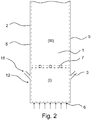
- Figures 1 and 2 show schematic sectional front views of the furnace of a bubbling fluidized bed boiler and a circulating fluidized bed boiler, respectively.
- the figures are basic views of the boilers and they are not intended to present the fluidized bed boiler on its correct scale.
- the fluidized bed 1 is in the lower part 12 of the furnace 2.
- the fluidized bed 1 consists of fluidized bed material, into which fluidizing gas is supplied through primary air nozzles 6 arranged in the bottom of the furnace 2, which primary air makes the fluidized bed material float and bubble.
- the fluidizing gas may be just air or it may be a mixture of air and a circulating gas.
- fuel is supplied above the fluidized bed 1 surface through one or several fuel feed pipes 3 located on two opposite furnace walls 5.
- Combustion air for volatile matter is supplied into the first combustion zone (I) along with the fuel supply.
- Part of the combustion air for volatile matter is supplied as a first combustion air supply mixed with the fuel supply and part of the combustion air for volatile matter is supplied as a second combustion air supply surrounding at least part of the fuel supply.
- the first and second combustion air supplies together direct the fuel into the fluidized bed 1.
- the fuel feeding means 18 are presented in more detail in figure 4 .
- a small amount of carrier air may be brought along with the fuel into the boiler, its main function being to prevent clogging of the supply chute.
- first combustion zone (I) The space confined between the height level of primary air nozzles 6 and the secondary air nozzles 7, which space contains the fluidized bed 1 and the volume above it all the way up to a level under the secondary air nozzles 7, forms a first combustion zone (I).
- fuel is supplied through fuel feed pipes 3
- fluidizing gas is supplied through primary air nozzles 6, and combustion air for volatile matter is supplied along with the fuel.
- Air conducted into the first combustion zone (I) along with the fuel supply is taken from the secondary air register, whereby it reduces the quantity of air to be supplied into the second combustion zone (II).
- a larger supply of air into the first combustion zone (I) will result in high temperatures in the first combustion zone (I).
- the fuel is made to ignite quickly and a major part of the fuel's volatile matter can be burnt before the second combustion zone (II) .
- Tertiary air is supplied above the secondary air nozzles 7 through tertiary air nozzles 16 arranged in the upper part of the furnace 2.
- the tertiary air nozzles 16 are usually placed 2 - 4 meters below the furnace nose.
- secondary air is supplied through the secondary air nozzles 7, to be mixed together with a flue gas flow rising upwards from the first combustion zone (I) and containing non-combusted gases and particles deriving from the fuel, which gases and particles will be further combusted in the second combustion zone (II).
- the burning of fuel continues further in a third combustion zone (III) beginning from the height level the tertiary air nozzles 16.
- the first combustion zone (I) and the second combustion zone (II) are substoichiometric zones, whereas the third combustion zone is a superstoichiometric zone, that is, the total air coefficient SR TOT in the third combustion zone (III) is over 1.
- the lower part 12 of the furnace comprises refractory lining 13 which protects the walls of the furnace 2 from erosion caused by fluidizing bed material and extends from the top surface of a fluidized bed to a height of 1.8 - 2.4 meters.
- the height of the refractory lining 13 may be different from the fuel supply height.
- the air coefficient SR VOL for volatile matter in the first combustion zone (I) is in a range of 0.9 - 1.00.
- the total air coefficient SR TOT is in a range of 0.75 - 0.85.
- the total air coefficient SR TOT is about 1.15.
- the reduction to molecular nitrogen of nitrogen oxides formed from the fuel is carried out mainly in two stages.
- first substoichiometric combustion zone (I) a major part of the volatile matter of the fuel and a part of the carbonization residue are burnt. This takes place in conditions which are substoichiometric as regards the air coefficient SR VOL in relation to the volatile matter of the fuel, whereby a lot of hydrocarbon radicals will result.
- second combustion zone (II) combustion air is supplied into the furnace from the secondary air nozzles 7 so much that substoichiometric combustion conditions are maintained, whereby the total air coefficient SR TOT in the second combustion zone (II) is in a range of 0.75 - 0.85.
- the solution according to the invention aims at optimizing the combustion of the fuel's volatile matter in the two first substoichiometric combustion zones (I) and (II) of the furnace.
- the solution does not change the air volume supplied into the furnace and not either the total air coefficient, but it changes the air distribution in the boiler, so that the air coefficient in relation to volatile matter is as high as possible at as low a level as possible in the furnace and for as long a time as possible before the secondary air level.
- Figure 2 shows a schematic sectional front view of the furnace of a circulating fluidized bed boiler.
- the fluidized bed 1 extends to the upper part of the furnace 2.
- the fluidized bed 1 consists of fluidized bed material, into which fluidizing gas is supplied through primary air nozzles 6 arranged in the bottom of the furnace 2, which primary air makes the fluidized bed material fluidize.
- the fluidizing gas may be just air or it may be a mixture of air and a circulating gas.
- fuel is supplied into the fluidized bed 1 through one or several fuel feed pipes 3 located on two opposite furnace walls 5.
- Combustion air for volatile matter is supplied into the first combustion zone (I) along with the fuel supply.
- Part of the combustion air for volatile matter is supplied as a first combustion air supply mixed with the fuel supply and part of the combustion air for volatile matter is supplied as a second combustion air supply surrounding at least part of the fuel supply.
- the first and second combustion air supplies together direct the fuel into the fluidized bed 1.
- the fuel feeding means 18 are presented in more detail in figure 4 .
- a small amount of carrier air may be brought along with the fuel into the boiler, its main function being to prevent clogging of the supply chute.
- fuel is supplied through fuel feed pipes 3
- fluidizing gas is supplied through primary air nozzles 6, and combustion air for volatile matter is supplied along with the fuel.
- Air conducted into the first combustion zone (I) along with the fuel supply is taken from the secondary air register, whereby it reduces the quantity of air to be supplied into the third combustion zone (III).
- a larger supply of air into the first combustion zone (I) will result in high temperatures in the first combustion zone (I).
- the upper part of the CFB boiler of figure 2 further comprises an exit chute and a separation system for separating solids from the flue gas (not presented) .
- the air coefficient SR VOL for volatile matter in the first combustion zone (I) is in a range of 0.9 - 1.00.
- the total air coefficient SR TOT is about 1.2.
- FIGS 3a-3e show the fuel feed pipe 3 and the at least one air feed channel 4 from the inside the furnace according to the first, second, third, fourth and fifth embodiment of the present invention.
- the fuel feed pipe 3 comprises a first outlet 14 for supplying fuel and combustion air for volatile matter into the furnace.
- the at least one air feed channel 4 comprises a second outlet 15 for supplying combustion air for volatile matter into the furnace.
- the cross-section of the fuel feed pipe 3 may be of any shape, e.g. rectangular or round.
- the air feed channel 4 may be one continuous air feed channel 4 or separate air feed channels 4 on different sides of the fuel feed pipe 3.
- one continuous air feed channel 4 surrounds the fuel feed pipe 3 on all sides, thereby forming a second combustion air supply around the whole fuel supply.
- one continuous air feed channel 4 surrounds the fuel feed pipe 3 on all sides except from below, thereby forming a second combustion air supply around three sides of the fuel supply, but not below it.
- three separate air feed channels 4 surround the fuel feed pipe 3 on all sides except from below, thereby forming a second combustion air supply around three sides of the fuel supply, but not below it.
- four separate air feed channels 4 surround the fuel feed pipe 3 on all sides, thereby forming a second combustion air supply around the whole fuel supply.
- FIG. 4 shows a schematic sectional view of the fuel feed pipe 3 and the air feed channel 4 according to one embodiment of the invention.
- the fuel feeding means 18 comprise a fuel feed pipe 3 and an air feed channel 4 around part of the length of the fuel feed pipe 3 and surrounding the fuel feed pipe 3 on all sides.
- the fuel feeding means 18 further comprise an inlet 8 for supplying combustion air for volatile matter along with the fuel.
- the fuel feed pipe 3 and the air feed channel 4 end in the first outlet 14 and the second outlet 15, respectively. Through these outlets fuel and combustion air for volatile matter are directed into the furnace.
- the inlet 8 is connected to secondary air for supplying secondary air as combustion air for volatile matter.
- the upper side of the fuel feed pipe 3 comprises a first opening for directing combustion air for volatile matter from the inlet 8 into the fuel feed pipe 3.
- the upper side of the air feed channel 4 comprises a second opening for directing combustion air for volatile matter from the inlet 8 into the air feed channel 4.
- the control dampers 11 direct 60 % of the combustion air for volatile matter from the inlet into the fuel feed pipe and 40 % of the combustion air for volatile matter into the air feed channel 4.
- the guide vanes 19 direct the air flow smoothly into the fuel feed pipe 3.
- the cross-sectional area of the fuel feed pipe 3 at the first outlet 14 and of the air feed channel 4 at the second outlet 15 is such that the velocity at which the combustion air for volatile matter is supplied in both the fuel feed pipe 3 and the air feed channel 4 is 15 to 20 m/s.
- Figure 5 shows a schematic perspective view of a bubbling fluidized bed boiler showing peat particles on boiler walls when combustion air for volatile matter is supplied using a method according to one embodiment of the invention.
- Figure 6 shows a schematic perspective view of a bubbling fluidized bed boiler showing peat particles on boiler walls when combustion air for volatile matter is supplied using a method according to prior art, i.e. when combustion air for volatile matter is supplied around the fuel supply but not trough the fuel feed pipe 3 mixed with the fuel.
- the peat particles of the fuel form slag 14 on boiler walls.
- Tables 1 and 2 show stage by stage the total air coefficients SR TOT and air coefficient in relation to volatile matter SR VOL in a bubbling fluidized bed boiler in which no combustion air for volatile matter is supplied (Table 1) and in a boiler in which combustion air for volatile matter is supplied along with the fuel as described above (Table 2) when using peat or wood as fuel.
- Table 1 shows stage by stage the total air coefficients SR TOT and air coefficient in relation to volatile matter SR VOL in a bubbling fluidized bed boiler in which no combustion air for volatile matter is supplied (Table 1) and in a boiler in which combustion air for volatile matter is supplied along with the fuel as described above (Table 2) when using peat or wood as fuel.
- Table 1 shows stage by stage the total air coefficients SR TOT and air coefficient in relation to volatile matter SR VOL in a bubbling fluidized bed boiler in which no combustion air for volatile matter is supplied
- Table 2 in a boiler in which combustion air for volatile matter is supplied along with the fuel as described above
- furnace air is supplied into the first combustion zone (I) mainly together with the fluidizing gas as fluidizing air and in connection with the fuel supply as carrier air.
- the small air volume used for cooling start-up burners has only a minor effect on the total air coefficient SR TOT of the first combustion zone (I).
- Table 1 Total air coefficients SR TOT and air coefficients in relation to volatile matter SR VOL in a bubbling fluidized bed boiler in which no combustion air for volatile matter is supplied.
- the air coefficient in relation to volatile matter of the fuel in the first combustion zone (I), that is, SR VOL is in a range of 0.65 - 0.75, whereby the combustion temperatures are low in the lower part of the furnace.
- Addition of secondary air at the beginning of the second combustion zone (II) and addition of tertiary air at the beginning of the third combustion zone (III) clearly raise the total air coefficient SR TOT .
- Table 2 shows the air distribution in a bubbling fluidized bed boiler, where additional air taken from the secondary air register and intended for the combustion of fuel's volatile matter in the first combustion zone (I) is supplied into the boiler furnace along with the fuel supply. Part of the combustion air for volatile matter is supplied as mixed with the fuel supply and part of the combustion air for volatile matter is supplied as surrounding at least part of the fuel supply.
- the air coefficient SR VOL in relation to volatile matter in the first combustion zone (I) is kept within an optimum range for the reduction of nitrogen oxides, which range is 0.9 - 1.0.
- Table 2 Total air coefficients SR TOT and air coefficients in relation to volatile matter SR VOL in a bubbling fluidized bed boiler in which combustion air for volatile matter is supplied along with the fuel.
- the combustion air for volatile matter supplied into the first combustion zone (I) along with the fuel supply clearly raises the total air coefficient.
- the total air coefficient is at the same level as in Table 1.
- the total air volume to be supplied into the bubbling fluidized bed boiler is the same as in the case shown in Table 1, but the air distribution is different, when in the solution according to Table 2 a part of the secondary air of Table 1 is supplied into the first combustion zone (I) along with the fuel supply.
Landscapes
- Engineering & Computer Science (AREA)
- Chemical & Material Sciences (AREA)
- Mechanical Engineering (AREA)
- General Engineering & Computer Science (AREA)
- Combustion & Propulsion (AREA)
- Dispersion Chemistry (AREA)
- Fluidized-Bed Combustion And Resonant Combustion (AREA)
Description
- The present invention relates to a method for feeding air to a fluidized bed boiler. The present invention further relates to a fluidized bed boiler and to fuel feeding means for a fluidized bed boiler.
- Fluidized bed boilers are in general use for producing energy from biofuels of various kinds and from oil-based waste. Fuels of this type are characterized in that the share of volatile matter is high in the dry matter of the fuel. The fuel used in fluidized bed boilers often contains fine and light particles, which are easily carried away with the fluidizing gas and secondary air into the upper parts of the furnace. Controlling combustion and reduction of nitrogen oxide emissions with this type of fuels is challenging.
- In the near future, new, significantly stricter nitrogen oxide (NOx) emission limits depending on the fuel power of the boiler are about to enter into force in the member states of the European Union (Industrial Emissions Directive, IED). There is thus the need for developing better ways to reduce nitrogen oxide emissions.
- There are two main types of fluidized bed boilers: bubbling fluidized bed boilers (BFB) and circulating fluidized bed boilers (CFB). In fluidized bed boilers, combustion is stabilized by a fluidized bed having a large thermal capacity. The fluidized bed consists of a fine incombustible material, such as sand, which is fluidized by supplying fluidizing gas into the bed from below. The main difference between BFB boilers and CFB boilers is in fluidization velocity. Low gas velocity is used in BFB boilers and the position of the solids layer is relatively stationary, forming a fluidized bed in the lower part of the furnace. In CFB boilers higher gases velocities are used sufficient to suspend the particle bed and entrain particles, which are recirculated via an external loop back into the fluidized bed.
- Nitrogen oxide emissions are conventionally reduced using staged air supply. The fuel is supplied on top of the fluidized bed or into the fluidized bed with the aid of carrier air, which is used for, among other things, preventing clogging of the fuel supply chutes. In the fluidized bed and above it fuel particles are dried, volatile matter is released, that is, pyrolysis occurs, and the carbonized residue is incinerated. Drying and pyrolysis are very fast events. The volatile matter released in pyrolysis comprises mainly methane CH4 and carbon monoxide CO as well as ammonia NH3 and hydrogen cyanide HCN. The volatile matter rises upwards in the furnace and it will burn when reaching an oxygen-containing region. In a fluidized bed boiler operating with staged air supply, the combustion of volatile matter takes place mainly under the effect of secondary air and partly also under the effect of tertiary air. The combustion of carbonized residue of fuel particles takes place under the effect of primary, secondary and tertiary air.
- It is possible with the aid of staged air supply to reduce the formation of nitrogen oxides in a bubbling fluidized bed boiler. In the presence of oxygen, NH3 and HCN react into nitrogen monoxide NO. By staging the air supply, reducing substoichiometric areas are formed in the furnace of the bubbling fluidized bed boiler. In these areas, NH3 and HCN formed from the fuel are reduced into molecular nitrogen in accordance with reaction equations (1) and (2):


- Additionally, nitrogen oxides are reduced with the aid of an internal re-burning reaction, in which hydrocarbon radicals formed in the pyrolysis will take part in reducing the nitrogen oxides. An example of such a reaction is described in reaction equation (3), in which -CHi acts as the hydrocarbon radical:

- Reducing areas are usually formed by adjusting the volume of primary and secondary air. The furnace is kept substoichiometric as regards oxygen until the supply of tertiary air, whereby the available dwell time for reactions (1) and (2) is maximized and the quantity of NH3 and HCN before the tertiary air level is minimized. The optimum total air coefficient SRTOT for NOx emissions before the tertiary air supply is just under 1, depending on the combustion temperature. The air needed for complete combustion of volatile matter and of the carbonized residue is brought into the furnace as tertiary air. NH3 and HCN remaining in the flue gases will oxidize into nitrogen oxides after the tertiary air supply.
- With these conventional measures in accordance with staged air supply it is possible to reduce nitrogen oxide emissions by approximately 30 % in comparison with non-staged air supply.
-
WO 2006084954 A1 describes a solution, which aims at reducing nitrogen oxide emissions of a bubbling fluidized bed boiler by using staged air supply in such a way that a part of the primary air, i.e. combustion air for volatile matter, is supplied into the furnace in connection with the fuel supply in the same direction as the fuel itself. The combustion air for volatile matter can be supplied either with the fuel or within the immediate vicinity of the fuel supply point in the same direction as the fuel itself. The quantity of combustion air for volatile matter is adjusted to be such that the combustion of volatile matter released from the fuel will take place in substoichiometric conditions in relation to the volatile matter. The air coefficient in relation to volatile matter, that is, SRVOL, in the primary air zone is as high as possible, however, less than 1. - In the method described in
WO 2006084954 A1 , the combustion air for volatile matter may supplied within the immediate vicinity of the fuel supply point in the same direction as the fuel itself. In order to increase the air coefficient for volatile matter SRVOL close to 1, the amount of combustion air for volatile matter supplied in connection with the fuel is such that the velocity of the air supplied parallelly with the fuel is high as compared to the velocity of the fuel supply. Depending on the pipe construction, the velocity of the combustion air for volatile matter may be, for instance, 30 - 40 m/s. The great velocity difference between the stream of combustion air for volatile matter and the fuel stream causes underpressure at the outlet of the fuel feed pipe. Equalization of pressures at the outlet of the fuel feed pipe causes mixing of the streams and spreading of the fuel feed particles to the walls of the furnace forming slags. Slagging prevents full utilization of the system and reduces boiler availability by increasing the need for maintenance. In addition, the desired flux flow of the fuel into the fluidized bed is not achieved. With such a high velocity, the combustion air for volatile matter crashes aggressively into the fluidized bed and results in escape of sand from the fluidized bed. As a consequence, the fluidized bed does not work in the way planned. An alternative way of supplying combustion air for volatile matter described inWO 2006084954 A1 is such that the combustion air for volatile matter is supplied together with the fuel. In this case, the fuel is not efficiently directed into the fluidized bed. Due to these drawbacks, reduction in nitrogen oxide emissions is not sufficient. -
GB 2286345 - The purpose of the invention is to provide a new type of method for feeding air to a fluidized bed boiler with improved fluid dynamics inside the furnace, thus enabling more efficient reduction of nitrogen oxide emissions of the boiler and improvement of the efficiency of the boiler. Further, the purpose of the invention is to provide a fluidized bed boiler and fuel feeding means for a fluidized bed boiler.
- The present invention relates to a method for feeding air to a fluidized bed boiler burning fuel according to
claim 1. The fluidized bed boiler comprises a fluidized bed and a boiler furnace comprising a first combustion zone (I). Air needed for burning the fuel in the fluidized bed is supplied in stages into the boiler furnace for causing substoichiometric combustion in the first combustion zone (I). The method comprises: - supplying primary air into the first combustion zone (I) from under the fluidized bed for fluidizing the bed material;
- supplying combustion air for volatile matter into the first combustion zone (I) along with the fuel supply.
- Part of the combustion air for volatile matter is supplied as a first combustion air supply mixed with the fuel supply and part of the combustion air for volatile matter is supplied as a second combustion air supply surrounding at least part of the fuel supply. The velocity at which the combustion air for volatile matter is supplied in both the first and the second combustion air supplies is 10 to 25 m/s.
- The present invention further relates to a fluidized bed boiler according to
claim 8. The fluidized bed boiler comprising a fluidized bed, a boiler furnace comprising furnace walls and a first combustion zone (I),
primary air nozzles under the fluidized bed for supplying primary air into the first combustion zone (I) for fluidizing the bed material,
at least one fuel feed pipe on at least one furnace wall in the first combustion zone (I) for supplying fuel into the fluidized bed, the at least one fuel feed pipe comprising a first outlet, and
an inlet for supplying combustion air for volatile matter into the first combustion zone (I) along with the fuel supply. - The boiler comprises at least one air feed channel around at least part of the length of the fuel feed pipe and surrounding at least part of the fuel feed pipe, the at least one air feed channel comprising a second outlet. Part of the combustion air for volatile matter is arranged to be supplied into the boiler furnace through the fuel feed pipe as a first combustion air supply mixed with the fuel supply and part of the combustion air for volatile matter is arranged to be supplied into the furnace through the at least one air feed channel as a second combustion air supply surrounding at least part of the fuel supply. The cross-sectional area of the fuel feed pipe at the first outlet and of the at least one air feed channel at the second outlet is arranged to be such that the velocity at which the combustion air for volatile matter is supplied in the first combustion air supply and in the second combustion air supply is 10 to 25 m/s.
- Disclosed is a fluidized bed boiler comprising a fluidized bed, a boiler furnace comprising furnace walls and a first combustion zone (I),
primary air nozzles under the fluidized bed for supplying primary air into the first combustion zone (I) for fluidizing the bed material,
at least one fuel feed pipe on at least one furnace wall in the first combustion zone (I) for supplying fuel into the fluidized bed, and
an inlet for supplying combustion air for volatile matter into the first combustion zone (I) along with the fuel supply. - The boiler comprises at least one air feed channel around at least part of the length of the fuel feed pipe and surrounding at least part of the fuel feed pipe. Part of the combustion air for volatile matter is arranged to be supplied into the boiler furnace through the fuel feed pipe as a first combustion air supply mixed with the fuel supply and part of the combustion air for volatile matter is arranged to be supplied into the furnace through the at least one air feed channel as a second combustion air supply surrounding at least part of the fuel supply.
- The present invention further relates to fuel feeding means for a fluidized bed boiler according to
claim 11, comprising at least one fuel feed pipe for supplying fuel into the fluidized bed, the fuel feed pipe comprising a first outlet, and an inlet for supplying combustion air for volatile matter along with the fuel supply. The fuel feeding means comprise at least one air feed channel around at least part of the length of the fuel feed pipe and surrounding at least part of the fuel feed pipe, the at least one air feed channel comprising a second outlet. Part of the combustion air for volatile matter is arranged to be supplied through the fuel feed pipe as a first combustion air supply mixed with the fuel supply and part of the combustion air for volatile matter is arranged to be supplied through the at least one air feed channel as a second combustion air supply surrounding at least part of the fuel supply. The cross-sectional area of the fuel feed pipe at the first outlet and of the at least one air feed channel at the second outlet is arranged to be such that the velocity at which the combustion air for volatile matter is supplied in the first combustion air supply and in the second combustion air supply is 10 to 25 m/s. - Further detailed characteristics and advantages are described in the dependent claims.
- Disclosed are fuel feeding means for a fluidized bed boiler comprising at least one fuel feed pipe for supplying fuel into the fluidized bed, and an inlet for supplying combustion air for volatile matter along with the fuel supply. The fuel feeding means comprise at least one air feed channel around at least part of the length of the fuel feed pipe and surrounding at least part of the fuel feed pipe. Part of the combustion air for volatile matter is arranged to be supplied through the fuel feed pipe as a first combustion air supply mixed with the fuel supply and part of the combustion air for volatile matter is arranged to be supplied through the at least one air feed channel as a second combustion air supply surrounding at least part of the fuel supply.
- The inventors surprisingly found out that when part of the combustion air for volatile matter is supplied as mixed with the fuel supply and part of the combustion air for volatile matter is supplied as surrounding at least part of the fuel supply in a manner where the velocities of the two air supplies are controlled, fluid dynamics at the outlet of the fuel feed pipe are improved. Flux flow of the fuel and the combustion air for volatile matter into the fluidized bed is achieved. Feeding of the fuel and combustion air for volatile matter into the fluidised bed is more easily controlled, thereby reducing slagging of the boiler walls and escape of sand from the fluidized bed. Improvements in fluid dynamics thus facilitate full utilization of the boiler. Maintenance intervals are extended, which improves boiler availability. Further, operating costs are reduced.
- According to the invention, combustion air for volatile matter is supplied as divided into first and second combustion air supplies. The first combustion air supply is mixed with the fuel supply. The second combustion air supply surrounds at least part of the fuel supply. The fuel is more efficiently migrated into the fluidized bed when it is mixed with combustion air for volatile matter, causing efficient combustion of the fuel. In addition, combustion air for volatile matter forms a curtain of combustion air around the fuel stream or part of the fuel stream, thereby directing the fuel stream, including fine fuel particles, into the fluidized bed and preventing escape of fuel particles to the upper parts of the furnace. The air curtain also prevents fuel particles from ending up on the boiler walls. If the fuel stream is not directed into the fluidized bed, fine fuel particles are easily captured and carried to the upper parts of the furnace by fluidizing air fed from the bottom of the furnace to fluidize the bed material. Because essentially all the fuel is forced into the fluidized bed, the amount of unburned fuel is minimized and combustion of the fuel is more complete. Also, the dwell time of the fuel in the furnace is increased and the combustion is easier to control.
- The velocity at which the combustion air for volatile matter is supplied in both the first and the second combustion air supplies is 10 to 25 m/s. The velocity at which the combustion air for volatile matter is supplied means the velocity of the combustion air for volatile matter at the outlet of the air feed pipe or the air feed channel. By controlling the velocities of air supplies the crash of air into the fluidized bed and escape of sand can be reduced. The velocity of the air supply depends on the cross-section of the pipe or channel in which the supply flows, i.e. the smaller the cross-section, the faster the flow. Good fluid dynamics at the outlet of the fuel feed pipe are achieved when the velocity at which the combustion air for volatile matter is supplied in both supplies is 10 to 25 m/s. According to CFD (Computational Fluid Dynamics) calculations, the overall fluid dynamics in fluidized bed boiler furnace relative to nitrogen oxide emissions are improved when output velocities of both combustion air supplies are in this velocity range. Because the combustion air for volatile matter is directed to the furnace both mixed with the fuel supply and surrounding at least part of the fuel supply, the total additional air flow needed to increase SRVOL near
value 1 is divided into larger cross-section of the pipe, and the velocity of the air is decreased. As a consequence, nitrogen oxide emissions are decreased and combustion is enhanced. Too high velocities end up in increasing nitrogen oxide emissions. - The method and the fluidized bed boiler according to the present invention lead to improved reduction in nitrogen oxide emissions. Better nitrogen oxide reduction is achieved when combustion air for volatile matter is supplied both mixed with the fuel supply and surrounding at least part of the fuel supply together, as compared to supplying combustion air for volatile matter either mixed with the fuel supply or surrounding the fuel supply solely or together but with a large velocity difference between the two air supplies. Similar results have been achieved for boilers of both high and low furnace load. In bubbling fluidized bed boilers of furnace loads of 144 MW/m3 and 120 MW/m3, nitrogen oxide emissions have been reduced by 100 - 150 mg/Nm3, thereby reducing overall nitrogen oxide emissions by 20 - 30 % as compared to conventional staged combustion. The above results are achieved when SRVOL in the first combustion zone is approximately 0.95 and the refractory lining in the lower part of the furnace extends to a height of 1.8 meters from the surface of the fluidized bed.
- The current invention also reduces the temperature of the flue gas at the furnace exit (Furnace Exit Gas Temperature, FEGT). Volatile matter released from the fuel is burnt as low in the furnace as possible. As a result, most of the volatile matter can be burnt before the second combustion zone. Also, the fuel particles are forced to the fluidized bed and therefore do not escape to the upper parts of the furnace. Thus the temperature in the upper part of the furnace and of flue gases at the nose of the furnace is not excessively risen. Low FEGT improves the efficiency of the boiler. Similar results have been achieved for boilers of both high and low furnace load. In bubbling fluidized bed boilers of furnace loads of 144 MW/m3 and 120 MW/m3, temperature of the flue gas at the furnace exit (FEGT) has been reduced by 50 to 100 °C as compared to conventional staged combustion. The above results are achieved when SRVOL in the first combustion zone is approximately 0.95 and the refractory lining in the lower part of the furnace extends to a height of 1.8 meters from the surface of the fluidized bed.
- Low FEGT also decreases fouling of the heat transfer surfaces. When the aim is to reduce nitrogen oxide emissions with means of combustion technology in existing boilers, the temperature of flue gases should not usually rise from the present-time values at the nose of the furnace. If in connection with changes in the combustion technology the flue gas temperature becomes too high or if the temperature distribution of flue gas is very uneven, this will lead to contamination of the heat transfer surfaces of the boiler's second draft, especially when burning fuels that contain lots of alkali metals. On the other hand, with chlorine-bearing fuels high flue gas temperatures may cause strong corrosion in the super-heater area.
- The first combustion zone (I) begins from the height level of the primary air nozzles and extends up to below the height level of secondary air nozzles. For a bubbling fluidized bed boiler, the length of the first combustion zone (I) may be optimized by optimizing the height of secondary air nozzles by the method described in
EP 2574841 A2 . In one embodiment, the method comprises supplying secondary air above the first combustion zone (I). In one embodiment, the fluidized bed boiler comprises a boiler furnace comprising secondary air nozzles on at least one furnace wall above the first combustion zone (I) for supplying secondary air above the first combustion zone (I). In one embodiment, the fluidized bed boiler comprises a boiler furnace comprising secondary air nozzles on at least one furnace wall above the first combustion zone (I) for supplying secondary air into the second combustion zone (II). - In one embodiment, the fluidized bed boiler is a bubbling fluidized bed boiler, and the method comprises supplying secondary air into the second combustion zone (II) located above the first combustion zone (I). The second combustion zone (II) begins from the height level of the secondary air nozzles and extends up to below the height level of tertiary air nozzles. The second combustion zone (II) is substoichiometric. In one embodiment, the fluidized bed boiler is a bubbling fluidized bed boiler, and the method comprises supplying tertiary air into a third combustion zone (III) located above the second combustion zone (II). In one embodiment, the fluidized bed boiler is a bubbling fluidized bed boiler which comprises tertiary air nozzles on at least one furnace wall above the second combustion zone (II) for supplying tertiary air into the third combustion zone (III). In one embodiment, the tertiary air nozzles are located 2 - 4 meters below the furnace nose.
- In one embodiment, the fluidized bed boiler is a circulating fluidized bed boiler, and the method comprises supplying secondary air into the third combustion zone (III) located above the first combustion zone (I). In a circulating fluidized bed boiler, the third combustion zone (III) begins from the height level of the secondary air nozzles and extends up to the height level of furnace nose. In the third combustion zone (III), the total air coefficient SRTOT is about 1.2.
- The first and second combustion zones (I,II) are substoichiometric. By substoichiometric combustion it is meant that the total air coefficient SRTOT is kept substoichiometric. The total air coefficient SRTOT is kept superstoichiometric in the third combustion zone (III), in which the combustion is completed.
- Part of the combustion air for volatile matter is supplied as a first combustion air supply mixed with the fuel supply. A small amount of carrier air may also be supplied with the fuel supply.
- Part of the combustion air for volatile matter is supplied as a second combustion air supply surrounding at least part of the fuel supply. In one embodiment, the second combustion air supply fully surrounds the fuel supply. In one embodiment, the second combustion air supply surrounds the fuel supply on three sides but not on side below the fuel supply. In one embodiment, the at least one air feed channel surrounds the fuel feed pipe on all sides.
- In one embodiment, the at least one air feed channel surrounds the fuel feed pipe on three sides but not on side below the fuel feed pipe. In one embodiment, the at least one air feed channel surrounds the fuel feed pipe on all sides. The at least one air feed channel may be one air feed channel or several separate air feed channels surrounding at least part of the fuel feed pipe.
- In one embodiment, at least part of the length of the fuel feed pipe is surrounded by at least one air feed channel. In one embodiment, at least part of the circumference or perimeter of the cross section of the fuel feed pipe is surrounded by at least one air feed channel. The inlet for supplying combustion air for volatile matter or the at least one air feed channel may contain means for directing the air flow, such as guide vanes.
- In one embodiment, the fuel is biofuel, peat or oil-based waste. In one embodiment, biofuel comprises wood and industrial sewage sludge. In one embodiment, oil-based waste comprises plastics waste. In one embodiment, the fluidized bed boiler is a circulating fluidized bed boiler and the fuel comprises coal.
- In one embodiment, several fuel feed pipes are located on two opposite furnace walls. The fuel feed pipe comprises a first outlet for directing fuel into the furnace. The outlets of the fuel feed pipes are usually located side by side at the same height. The cross-section of the fuel feed pipe may be of any shape. In one embodiment, the cross-section of the fuel feed pipe is rectangular. In one embodiment, the cross-section of the fuel fee pipe is round.
- The bed material is fluidized by supplying fluidizing gas from under the fluidized bed. In one embodiment, fluidizing gas is supplied trough primary air nozzles. The fluidizing gas may consist solely of primary air or it may be a mixture of primary air and an inert gas, such as flue gas. The fluidizing gas is set to flow with such a velocity that the particles in the fluidized bed are in continuous motion and the bed efficiently mixes together the bed material and the fuel supplied into it. In a BFB boiler the fluidizing gas velocity is set such that the particles will not escape along with the gas flow into the upper part of the boiler but will form a fluidized bed in the lower part of the boiler. In a CFB boiler, the fluidizing gas velocity is set such that the fluidized bed extends to the upper part of the boiler.
-
EP 2574841 A2 discloses ways to adjust certain boiler parameters, which may be used together with the current invention for improving nitrogen oxide reduction. For BFB boilers the distance of the fuel supply openings from the surface of the bubbling fluidized bed described inEP 2574841 A2 may be used to improve nitrogen oxide reduction. For both BFB and CFB boilers, the vertical supply angle and horizontal supply angle of the fuel chutes, the arrangement of secondary and tertiary air nozzles in rows including nozzles blowing a small, medium and large air jet, and the side air nozzles placed between the outermost fuel supply chutes and the side wall described inEP 2574841 A2 may be used to improve nitrogen oxide reduction. - In addition to primary air, the first combustion zone (I) is supplied with combustion air for volatile matter in order to enhance nitrogen oxide reduction. The amount of primary air supplied into the first combustion zone (I) as a fluidizing gas or as a part of it does not change as compared to conventional fluidized bed combustion. The total amount of combustion air in the first combustion zone (I) is thus increased by adding combustion air for volatile matter. In one embodiment, the air coefficient in relation to volatile matter SRVOL in the first combustion zone (I) is in the substoichiometric area. That is, SRVOL is below 1.
- The air coefficient or the stoichiometric ratio SR tells how much air must be used for the combustion in comparison with the theoretical (stoichiometric) volume of air needed for complete combustion of the fuel. In substoichiometric combustion, the air coefficient SR is under 1, and in superstoichiometric combustion the air coefficient SR is over 1.
- Since SRVOL is in substoichiometric area, combustion of volatile matter released from the fuel in pyrolysis takes place in substoichiometric conditions in relation to volatile matter. In one embodiment, the air coefficient in relation to volatile matter is below 1, but as high as possible in order to enhance combustion of volatile matter in the first combustion zone (I). The higher the air coefficient SRVOL in relation to volatile matter, the more quickly the volatile matter will burn, at the same time causing a high local temperature and forming a maximum quantity of hydrocarbon radicals, which are needed for the reduction of nitrogen oxides formed from the fuel. Most of the volatile matter can be burnt in the first combustion zone (I) before the supply of secondary air. In one embodiment, the total air coefficient SRTOT in the first combustion zone is substoichiometric.
- In one embodiment the air coefficient in relation to volatile matter SRVOL in the first combustion zone (I) is 0.9 - 1.0. When the air coefficient in relation to volatile matter SRVOL in the first combustion zone (I) is 0.9 - 1.0, nitrogen oxides are efficiently reduced, whereby a major part of the fuel's volatile matter will burn already in the first combustion zone (I). In one embodiment the air coefficient in relation to volatile matter SRVOL in the first combustion zone (I) is 0.95 - 1.0. The optimum air coefficient in relation to volatile matter SRVOL in the first combustion zone (I) depends on the fuel, because different fuels have different contents of volatile matter.
- In one embodiment the boiler is a bubbling fluidized bed boiler and the boiler furnace comprises a second combustion zone (II) located above the first combustion zone (I), and the total air coefficient SRTOT in the second combustion zone (II) is 0.75 - 0.85. In one embodiment the total air coefficient SRTOT in the second combustion zone (II) is 0.8. In one embodiment the total air coefficient SRTOT in the second combustion zone (II) is 0.75 - 0.85. In one embodiment the total air coefficient SRTOT in the second combustion zone (II) is 0.8. Substoichiometric conditions are maintained above the first combustion zone (I).
- In one embodiment, the combustion air for volatile matter comprises secondary air. In one embodiment the combustion air for volatile matter consists of secondary air. The amount of secondary air provided above the first combustion zone (I) is decreased correspondingly. In one embodiment, part of the secondary air is supplied as combustion air for volatile matter into the first combustion zone (I). In one embodiment, the temperature of the combustion air for volatile matter is 150 to 250 °C. Secondary air is typically preheated in order to enhance combustion in the furnace, the temperature of secondary air in a fluidized bed boiler typically being in a range of 150 - 250 °C. As a result of mixing hot combustion air for volatile matter with the fuel supply, drying of the fuel particles and subsequent pyrolysis already begin inside the fuel feed pipe. Consequently, combustion of the fuel begins earlier and is enhanced in the lower part of the furnace, thereby increasing the temperature in the lower part of the furnace. The time available for combustion is increased. When hot combustion air for volatile matter is used, the result of combustion is better. Most of the volatile matter released from the fuel in pyrolysis is burnt in the first combustion zone before supply of secondary air. In addition, mixing of the combustion air for volatile matter with the fuel is improved by the high temperature. The high temperature of the combustion air for volatile matter also keeps the fuel supply chutes dry and clean, and no separate "fluidizing air" is needed in the supply chute for cleaning the chute.
- In one embodiment, the fluidized bed boiler comprises secondary air nozzles on at least one furnace wall above the first combustion zone (I) for supplying secondary air above the first combustion zone (I), and the inlet is connected to the secondary air for supplying secondary air at least as part of the combustion air for volatile matter. In one embodiment, the inlet is connected to the secondary air for supplying secondary air as the combustion air for volatile matter. In one embodiment, the temperature of the combustion air for volatile matter is arranged to be 150 to 250°C.
- In one embodiment the velocity at which the combustion air for volatile matter is supplied in both the first and the second combustion air supplies is 12 to 20 m/s. Good fluid dynamics are achieved when the velocity is in this range. In one embodiment the velocity at which the combustion air for volatile matter is supplied in both the first and the second combustion air supplies is 15 to 20 m/s. In one embodiment, the velocity at which the combustion air for volatile matter is supplied in the first combustion air supply is the same as the velocity at which the combustion air for volatile matter is supplied in the second combustion air supply. This way, flux flow is achieved directing the fuel into the fluidized bed.
- In one embodiment, the velocity at which the combustion air for volatile matter is supplied in the first combustion air supply is 12 to 20 m/s. In one embodiment, the velocity at which the combustion air for volatile matter is supplied in the first combustion air supply is 15 to 20 m/s. In one embodiment, the velocity at which the combustion air for volatile matter is supplied in the first combustion air supply is 15 m/s.
- In one embodiment the velocity at which the combustion air for volatile matter is supplied in the second combustion air supply is 12 to 20 m/s. In one embodiment the velocity at which the combustion air for volatile matter is supplied in the second combustion air supply is 15 to 20 m/s. In one embodiment the velocity at which the combustion air for volatile matter is supplied in the second combustion air supply is 15 m/s.
- The first combustion air supply comprises 60 to 70 % of the combustion air for volatile matter and the second combustion air supply comprises 30 to 40 % of the combustion air for volatile matter. According to CFD calculations and confirmed by experiments in fluidized bed boilers, fluid dynamics in the furnace in relation to reduction of nitrogen oxide emissions are improved when 60 to 70 % of combustion air for volatile matter is supplied as mixed with the fuel supply and from 30 to 40 % of combustion air for volatile matter is supplied as surrounding the fuel supply. The fuel particles end up into the fluidized bed, thereby preventing fouling of the heat transfer surfaces of the boiler. This solution reduces nitrogen oxide emission levels to about 250 mg/Nm3.
- In one embodiment the fuel is supplied into the first combustion zone (I) through a fuel feed pipe, and the first combustion air supply is mixed with the fuel supply and supplied into the furnace simultaneously with the fuel supply through said fuel feed pipe. In one embodiment, the fuel supply and first combustion air supply are mixed in the fuel feed pipe.
- In one embodiment the second combustion air supply is supplied into the first combustion zone (I) through at least one air feed channel arranged around at least part of the length of the fuel feed pipe and surrounding at least part of the fuel feed pipe.
- In one embodiment the first combustion air supply and the second combustion air supply are simultaneously supplied into the first combustion zone (I).
- In one embodiment the method is carried out in a bubbling fluidized bed boiler, in which the fluidized bed has a top surface and the boiler furnace has a lower part which is equipped with a refractory lining extending to a height of 1.8 - 2.4 meters from the top surface of the fluidized bed. In one embodiment, the boiler is a bubbling fluidized bed boiler, in which the fluidized bed (1) has a top surface and the boiler furnace has a lower part which is equipped with a refractory lining extending to a height of 1.8 - 2.4 meters from the top surface of the fluidized bed.
- In one embodiment, the refractory lining extends to a height of 1.8 - 2.0 meters from the top surface of the fluidized bed. Typically, the temperature of the fluidized bed should be kept within a range of 800 - 900 °C. If the bed temperature rises much above 900 °C and the fuel contains much alkali metals, this could lead to agglomeration of ash particles in the fluidized bed. One way of lowering the fluidized bed temperature in a bubbling fluidized bed boiler is by reducing the boiler's refractory lining surface in the region between the primary air level and the secondary air level. In typical bubbling fluidized bed boilers of today, the refractory lining surface in the lower part of the furnace is made by laying bricks to a height of about 2.5 - 5 meters from the surface of the bubbling fluidized bed. The purpose of the refractory lining is to protect the boiler's water pipes against corrosion and contamination, but at the same time it also increases the temperatures in the part above the fluidized bed, because the refractory lining prevents radiation heat transfer to the water pipes lining the furnace. When the refractory lining is lowered, the generated heat is more efficiently transferred into the water pipes. Consequently, the temperature of the flue gas in the upper part of the furnace is decreased.
- The fuel feed pipe comprises a first opening for directing part of the combustion air for volatile matter as a first combustion air supply from the inlet into the fuel feed pipe, and the at least one air feed channel comprises a second opening for directing part of the combustion air for volatile matter as a second combustion air supply from the inlet into the at least one air feed channel. The openings may be on any side of the fuel feed pipe or the air feed channel.
- At least one of the first and second openings comprises at least one control damper for directing 60 to 70 % of the combustion air for volatile matter from the inlet into the fuel feed pipe and 30 to 40 % of the combustion air for volatile matter from the inlet into the at least one air feed channel. In one embodiment, a first control damper directs 60% of the combustion air for volatile matter from the inlet into the fuel feed pipe. In one embodiment, a second control damper directs 40% of the combustion air for volatile matter from the inlet into the at least one air feed channel.
- The fuel feed pipe comprises a first outlet and the at least one air feed channel comprises a second outlet and the cross-sectional area of the fuel feed pipe at the first outlet and of the at least one air feed channel at the second outlet is arranged to be such that the velocity at which the combustion air for volatile matter is supplied in the first combustion air supply and in the second combustion air supply is 10 to 25 m/s. In one embodiment, the velocity at which the combustion air for volatile matter is supplied in the first combustion air supply and in the second combustion air supply is arranged to be 12 to 25 m/s. In one embodiment, the velocity at which the combustion air for volatile matter is supplied in the first combustion air supply and in the second combustion air supply is arranged to be 15 to 25 m/s. In one embodiment, the velocity at which the combustion air for volatile matter is supplied in the first combustion air supply and in the second combustion air supply is arranged to be 15 m/s. In one embodiment, the velocity at which the combustion air for volatile matter is supplied in the first combustion air supply is arranged to be the same as in the second combustion air supply.
- The amount of combustion air for volatile matter is determined by the amount of primary air supplied into the first combustion zone (I) so that the value of SRVOL in the first combustion zone (I) is in the correct area. The velocity of the combustion air for volatile matter in the fuel feed pipe is affected by the mass flow of the air and the cross-section of the fuel feed pipe. Similarly, the velocity of the combustion air for volatile matter in the at least one air feed channel is affected by the mass flow of air and the cross-section of the at least one air feed channel. The velocity of the combustion air for volatile matter in the fuel feed pipe is also affected by the mass flow of fuel.
- Several advantages are achieved by using the current invention. Fluid dynamics in the furnace are improved by supplying part of the combustion air for volatile matter as mixed with the fuel supply and part of the combustion air for volatile matter as surrounding at least part of the fuel supply. Controlled feed of fuel and air into the fluidised bed reduce slagging of the boiler walls and escape of sand from the fluidized bed. Improvements in fluid dynamics thus facilitate full utilization of the boiler. Boiler availability and efficiency is improved since maintenance intervals are extended. Further, operating costs are reduced.
- Improvements in fluid dynamics also facilitate more efficient reduction in nitrogen oxide emissions. The nitrogen oxide emissions may be reduced to 250 - 300 mg/Nm3. The combustion air for volatile matter supplied as described forces the fuel into the fluidized bed, thereby minimizing the amount of unburned fuel and resulting in more complete combustion of the fuel. Also, dwell time of the fuel in the furnace is increased and the combustion is easier to control. In addition, the high temperature of the secondary air used as combustion air for volatile matter enhances combustion and increases the temperature in the lower part of the furnace as well as keeps the fuel supply chutes clean and dry. The temperature of flue gas at the furnace exit (FEGT) is also reduced, since combustion takes place lower in the furnace. Also, low FEGT reduces corrosion in the super heater area and fouling of heat transfer surfaces is reduced. The temperature of flue gas may be further reduced by lowering the refractory lining in the lower part of the furnace, thereby enhancing heat transfer in the lower part of the furnace.
- The accompanying drawings, which are included to provide a further understanding of the invention and constitute a part of this specification, illustrate embodiments of the invention and together with the description help to explain the principles of the invention. In the drawings:
-
Fig. 1 is schematic sectional front view of the furnace of a bubbling fluidized bed boiler (BFB), -
Fig. 2 is schematic sectional front view of the furnace of a circulating fluidized bed boiler (CFB), -
Figs. 3a-3e show the fuel feed pipe and the air feed channel from the inside the furnace according to a first, second, third, fourth and fifth embodiment of the present invention, -
Fig. 4 is a schematic sectional view of the fuel feed pipe and the air feed channel according to one embodiment of the invention. -
Fig. 5 is a schematic perspective view of a bubbling fluidized bed boiler showing peat particles on boiler walls when combustion air for volatile matter is supplied using a method according to one embodiment of the invention. -
Fig. 6 is a schematic perspective view of a bubbling fluidized bed boiler showing peat particles on boiler walls when combustion air for volatile matter is supplied using a method according to prior art. -
Figures 1 and2 show schematic sectional front views of the furnace of a bubbling fluidized bed boiler and a circulating fluidized bed boiler, respectively. The figures are basic views of the boilers and they are not intended to present the fluidized bed boiler on its correct scale. - In the BFB boiler of
figure 1 , thefluidized bed 1 is in thelower part 12 of thefurnace 2. Thefluidized bed 1 consists of fluidized bed material, into which fluidizing gas is supplied throughprimary air nozzles 6 arranged in the bottom of thefurnace 2, which primary air makes the fluidized bed material float and bubble. The fluidizing gas may be just air or it may be a mixture of air and a circulating gas. - In
figure 1 , fuel is supplied above thefluidized bed 1 surface through one or severalfuel feed pipes 3 located on twoopposite furnace walls 5. Combustion air for volatile matter is supplied into the first combustion zone (I) along with the fuel supply. Part of the combustion air for volatile matter is supplied as a first combustion air supply mixed with the fuel supply and part of the combustion air for volatile matter is supplied as a second combustion air supply surrounding at least part of the fuel supply. The first and second combustion air supplies together direct the fuel into thefluidized bed 1. As a result, fuel particles and sand will not escape from thefluidized bed 1 when the mixture of air and fuel hits the top surface of the bubblingfluidized bed 1. The fuel feeding means 18 are presented in more detail infigure 4 . A small amount of carrier air may be brought along with the fuel into the boiler, its main function being to prevent clogging of the supply chute. - In
figure 1 , secondary air is supplied into thefurnace 2 fromsecondary air nozzles 7 located above the fuel supply level on twoopposite furnace walls 5, the reference number of which walls are not presented infigure 1 . - The space confined between the height level of
primary air nozzles 6 and thesecondary air nozzles 7, which space contains thefluidized bed 1 and the volume above it all the way up to a level under thesecondary air nozzles 7, forms a first combustion zone (I). Into the first combustion zone (I), fuel is supplied throughfuel feed pipes 3, fluidizing gas is supplied throughprimary air nozzles 6, and combustion air for volatile matter is supplied along with the fuel. Air conducted into the first combustion zone (I) along with the fuel supply is taken from the secondary air register, whereby it reduces the quantity of air to be supplied into the second combustion zone (II). A larger supply of air into the first combustion zone (I) will result in high temperatures in the first combustion zone (I). When air is supplied into thefurnace 2 along with the fuel supply, the fuel is made to ignite quickly and a major part of the fuel's volatile matter can be burnt before the second combustion zone (II) . - Tertiary air is supplied above the
secondary air nozzles 7 throughtertiary air nozzles 16 arranged in the upper part of thefurnace 2. Thetertiary air nozzles 16 are usually placed 2 - 4 meters below the furnace nose. - The space confined between the
secondary air nozzles 7 and thetertiary air nozzles 16, which space begins from the height level of thesecondary air nozzles 7 and ends under thetertiary air nozzles 16, forms a second combustion zone (II). Into the second combustion zone (II), secondary air is supplied through thesecondary air nozzles 7, to be mixed together with a flue gas flow rising upwards from the first combustion zone (I) and containing non-combusted gases and particles deriving from the fuel, which gases and particles will be further combusted in the second combustion zone (II). - The burning of fuel continues further in a third combustion zone (III) beginning from the height level the
tertiary air nozzles 16. The first combustion zone (I) and the second combustion zone (II) are substoichiometric zones, whereas the third combustion zone is a superstoichiometric zone, that is, the total air coefficient SRTOT in the third combustion zone (III) is over 1. - In
figure 1 , thelower part 12 of the furnace comprisesrefractory lining 13 which protects the walls of thefurnace 2 from erosion caused by fluidizing bed material and extends from the top surface of a fluidized bed to a height of 1.8 - 2.4 meters. The height of therefractory lining 13 may be different from the fuel supply height. - The air coefficient SRVOL for volatile matter in the first combustion zone (I) is in a range of 0.9 - 1.00. In the second combustion zone (II), the total air coefficient SRTOT is in a range of 0.75 - 0.85. In the third combustion zone (III), the total air coefficient SRTOT is about 1.15.
- The reduction to molecular nitrogen of nitrogen oxides formed from the fuel is carried out mainly in two stages. In the first substoichiometric combustion zone (I) a major part of the volatile matter of the fuel and a part of the carbonization residue are burnt. This takes place in conditions which are substoichiometric as regards the air coefficient SRVOL in relation to the volatile matter of the fuel, whereby a lot of hydrocarbon radicals will result. In the second combustion zone (II), combustion air is supplied into the furnace from the
secondary air nozzles 7 so much that substoichiometric combustion conditions are maintained, whereby the total air coefficient SRTOT in the second combustion zone (II) is in a range of 0.75 - 0.85. - The solution according to the invention aims at optimizing the combustion of the fuel's volatile matter in the two first substoichiometric combustion zones (I) and (II) of the furnace. The solution does not change the air volume supplied into the furnace and not either the total air coefficient, but it changes the air distribution in the boiler, so that the air coefficient in relation to volatile matter is as high as possible at as low a level as possible in the furnace and for as long a time as possible before the secondary air level.
-
Figure 2 shows a schematic sectional front view of the furnace of a circulating fluidized bed boiler. In the CFB boiler offigure 2 , thefluidized bed 1 extends to the upper part of thefurnace 2. Thefluidized bed 1 consists of fluidized bed material, into which fluidizing gas is supplied throughprimary air nozzles 6 arranged in the bottom of thefurnace 2, which primary air makes the fluidized bed material fluidize. The fluidizing gas may be just air or it may be a mixture of air and a circulating gas. - In
figure 2 , fuel is supplied into thefluidized bed 1 through one or severalfuel feed pipes 3 located on twoopposite furnace walls 5. Combustion air for volatile matter is supplied into the first combustion zone (I) along with the fuel supply. Part of the combustion air for volatile matter is supplied as a first combustion air supply mixed with the fuel supply and part of the combustion air for volatile matter is supplied as a second combustion air supply surrounding at least part of the fuel supply. The first and second combustion air supplies together direct the fuel into thefluidized bed 1. As a result, fuel particles and sand will not escape from thefluidized bed 1 when the mixture of air and fuel hits the top surface of the bubblingfluidized bed 1. The fuel feeding means 18 are presented in more detail infigure 4 . A small amount of carrier air may be brought along with the fuel into the boiler, its main function being to prevent clogging of the supply chute. - In
figure 2 , secondary air is supplied into thefurnace 2 fromsecondary air nozzles 7 located above the fuel supply level on twoopposite furnace walls 5, the reference number of which walls are not presented infigure 2 . - The space confined between the height level of
primary air nozzles 6 and thesecondary air nozzles 7, which space contains part of thefluidized bed 1 all the way up to a level under thesecondary air nozzles 7, forms a first, substoichiometric combustion zone (I). Into the first combustion zone (I), fuel is supplied throughfuel feed pipes 3, fluidizing gas is supplied throughprimary air nozzles 6, and combustion air for volatile matter is supplied along with the fuel. Air conducted into the first combustion zone (I) along with the fuel supply is taken from the secondary air register, whereby it reduces the quantity of air to be supplied into the third combustion zone (III). A larger supply of air into the first combustion zone (I) will result in high temperatures in the first combustion zone (I). - The space above the
secondary air nozzles 7, which space begins from the height level of thesecondary air nozzles 7 and extends to the upper part of thefurnace 2, forms a third, superstoichiometric combustion zone (III). Into the third combustion zone (III), secondary air is supplied through thesecondary air nozzles 7, to be mixed together with a flue gas flow rising upwards from the first combustion zone (I). The upper part of the CFB boiler offigure 2 further comprises an exit chute and a separation system for separating solids from the flue gas (not presented) . - The air coefficient SRVOL for volatile matter in the first combustion zone (I) is in a range of 0.9 - 1.00. In the third combustion zone (III), the total air coefficient SRTOT is about 1.2.
-
Figures 3a-3e show thefuel feed pipe 3 and the at least oneair feed channel 4 from the inside the furnace according to the first, second, third, fourth and fifth embodiment of the present invention. Thefuel feed pipe 3 comprises afirst outlet 14 for supplying fuel and combustion air for volatile matter into the furnace. The at least oneair feed channel 4 comprises asecond outlet 15 for supplying combustion air for volatile matter into the furnace. The cross-section of thefuel feed pipe 3 may be of any shape, e.g. rectangular or round. Theair feed channel 4 may be one continuousair feed channel 4 or separateair feed channels 4 on different sides of thefuel feed pipe 3. - In
figures 3a and 3d , one continuousair feed channel 4 surrounds thefuel feed pipe 3 on all sides, thereby forming a second combustion air supply around the whole fuel supply. Infigure 3b , one continuousair feed channel 4 surrounds thefuel feed pipe 3 on all sides except from below, thereby forming a second combustion air supply around three sides of the fuel supply, but not below it. Infigure 3c , three separateair feed channels 4 surround thefuel feed pipe 3 on all sides except from below, thereby forming a second combustion air supply around three sides of the fuel supply, but not below it. Infigure 3e , four separateair feed channels 4 surround thefuel feed pipe 3 on all sides, thereby forming a second combustion air supply around the whole fuel supply. -
Figure 4 shows a schematic sectional view of thefuel feed pipe 3 and theair feed channel 4 according to one embodiment of the invention. The fuel feeding means 18 comprise afuel feed pipe 3 and anair feed channel 4 around part of the length of thefuel feed pipe 3 and surrounding thefuel feed pipe 3 on all sides. The fuel feeding means 18 further comprise aninlet 8 for supplying combustion air for volatile matter along with the fuel. Thefuel feed pipe 3 and theair feed channel 4 end in thefirst outlet 14 and thesecond outlet 15, respectively. Through these outlets fuel and combustion air for volatile matter are directed into the furnace. Theinlet 8 is connected to secondary air for supplying secondary air as combustion air for volatile matter. The upper side of thefuel feed pipe 3 comprises a first opening for directing combustion air for volatile matter from theinlet 8 into thefuel feed pipe 3. The upper side of theair feed channel 4 comprises a second opening for directing combustion air for volatile matter from theinlet 8 into theair feed channel 4. Thecontrol dampers 11 direct 60 % of the combustion air for volatile matter from the inlet into the fuel feed pipe and 40 % of the combustion air for volatile matter into theair feed channel 4. The guide vanes 19 direct the air flow smoothly into thefuel feed pipe 3. The cross-sectional area of thefuel feed pipe 3 at thefirst outlet 14 and of theair feed channel 4 at thesecond outlet 15 is such that the velocity at which the combustion air for volatile matter is supplied in both thefuel feed pipe 3 and theair feed channel 4 is 15 to 20 m/s. -
Figure 5 shows a schematic perspective view of a bubbling fluidized bed boiler showing peat particles on boiler walls when combustion air for volatile matter is supplied using a method according to one embodiment of the invention.Figure 6 shows a schematic perspective view of a bubbling fluidized bed boiler showing peat particles on boiler walls when combustion air for volatile matter is supplied using a method according to prior art, i.e. when combustion air for volatile matter is supplied around the fuel supply but not trough thefuel feed pipe 3 mixed with the fuel. The peat particles of thefuel form slag 14 on boiler walls. When combustion air for volatile matter is supplied using the method according to the invention (figure 5 ), slagging of boiler walls is reduced as compared to the method according to prior art (figure 6 ) . - In the following, the invention is described by referring to examples presented in Tables 1 and 2. The tables show stage by stage the total air coefficients SRTOT and air coefficient in relation to volatile matter SRVOL in a bubbling fluidized bed boiler in which no combustion air for volatile matter is supplied (Table 1) and in a boiler in which combustion air for volatile matter is supplied along with the fuel as described above (Table 2) when using peat or wood as fuel. The total air coefficient SRTOT increases in the vertical direction of the furnace as more air is supplied into the furnace.
- In table 1, furnace air is supplied into the first combustion zone (I) mainly together with the fluidizing gas as fluidizing air and in connection with the fuel supply as carrier air. The small air volume used for cooling start-up burners has only a minor effect on the total air coefficient SRTOT of the first combustion zone (I).
Table 1. Total air coefficients SRTOT and air coefficients in relation to volatile matter SRVOL in a bubbling fluidized bed boiler in which no combustion air for volatile matter is supplied. Wood SRTOT Wood SRVOL Peat SRTOT Peat SRVOL Fluidizing air 0.40 0.56 0.35 0.60 Carrier air 0.45 0.62 0.40 0.68 Cooling air for start-up burners 0.47 0.66 0.43 0.73 Secondary air 0.80 1.11 0.80 1.36 Cooling air for load bearing burners 0.83 1.15 0.83 1.41 Tertiary air 1.15 1.59 1.15 1.95 - In this air distribution, the air coefficient in relation to volatile matter of the fuel in the first combustion zone (I), that is, SRVOL, is in a range of 0.65 - 0.75, whereby the combustion temperatures are low in the lower part of the furnace. Addition of secondary air at the beginning of the second combustion zone (II) and addition of tertiary air at the beginning of the third combustion zone (III) clearly raise the total air coefficient SRTOT.
- Table 2 shows the air distribution in a bubbling fluidized bed boiler, where additional air taken from the secondary air register and intended for the combustion of fuel's volatile matter in the first combustion zone (I) is supplied into the boiler furnace along with the fuel supply. Part of the combustion air for volatile matter is supplied as mixed with the fuel supply and part of the combustion air for volatile matter is supplied as surrounding at least part of the fuel supply. The air coefficient SRVOL in relation to volatile matter in the first combustion zone (I) is kept within an optimum range for the reduction of nitrogen oxides, which range is 0.9 - 1.0.
Table 2. Total air coefficients SRTOT and air coefficients in relation to volatile matter SRVOL in a bubbling fluidized bed boiler in which combustion air for volatile matter is supplied along with the fuel. Wood SRTOT Wood SRVOL Peat SRTOT Peat SRVOL Fluidizing air 0.40 0.56 0.44 0.74 Carrier air 0.45 0.62 0.48 0.82 Combustion air for volatile matter 0.62 0.86 0.56 0.95 Cooling air for start-up burners 0.65 0.90 0.59 1.00 Secondary air 0.80 1.11 0.80 1.36 Cooling air for load bearing burners 0.83 1.15 0.83 1.41 Tertiary air 1.15 1.59 1.15 1.95 - In this case, the combustion air for volatile matter supplied into the first combustion zone (I) along with the fuel supply clearly raises the total air coefficient. However, after the supply of secondary air, the total air coefficient is at the same level as in Table 1. Thus, the total air volume to be supplied into the bubbling fluidized bed boiler is the same as in the case shown in Table 1, but the air distribution is different, when in the solution according to Table 2 a part of the secondary air of Table 1 is supplied into the first combustion zone (I) along with the fuel supply.
- It is obvious to a person skilled in the art that with the advancement of technology, the basic idea of the invention may be implemented in various ways. The invention and its embodiments are thus not limited to the examples described above; instead they may vary within the scope of the claims.
Claims (11)
- A method for feeding air to a fluidized bed boiler burning fuel, the fluidized bed boiler comprising a fluidized bed (1) and a boiler furnace (2) comprising a first combustion zone (I), in which method air needed for burning the fuel in the fluidized bed (1) is supplied in stages into the boiler furnace (2) for causing substoichiometric combustion in the first combustion zone (I), and which method comprises:- supplying primary air into the first combustion zone (I) from under the fluidized bed (1) for fluidizing the bed material;- supplying combustion air for volatile matter into the first combustion zone (I) along with the fuel supply,characterized in that- part of the combustion air for volatile matter is supplied as a first combustion air supply mixed with the fuel supply and part of the combustion air for volatile matter is supplied as a second combustion air supply surrounding at least part of the fuel supply, wherein the first combustion air supply comprises 60 to 70 % of the combustion air for volatile matter and the second combustion air supply comprises 30 to 40 % of the combustion air for volatile matter, and- the velocity at which the combustion air for volatile matter is supplied in both the first and the second combustion air supplies is 10 to 25 m/s.
- The method according to claim 1, char- acterized in that the air coefficient in relation to volatile matter SRVOL in the first combustion zone (I) is 0.9 - 1.0.
- The method according to claim 1 or 2, characterized in that the boiler is a bubbling fluidized bed boiler and the boiler furnace (2) comprises a second combustion zone (II) located above the first combustion zone (I), and the total air coefficient SRTOT in the second combustion zone (II) is 0.75 - 0.85.
- The method according to any of the preceding claims, characterized in that the combustion air for volatile matter comprises secondary air.
- The method according to any of the preceding claims, characterized in that, the fuel is supplied into the first combustion zone (I) through a fuel feed pipe (3), and the first combustion air supply is mixed with the fuel supply and supplied into the boiler furnace (2) simultaneously with the fuel supply through said fuel feed pipe (3).
- The method according to any of the preceding claims, characterized in that the second combustion air supply is supplied into the first combustion zone (I) through at least one air feed channel (4) arranged around at least part of the length of the fuel feed pipe (3) and surrounding at least part of the fuel feed pipe (3).
- The method according to any of the preceding claims, characterized in that the first combustion air supply and the second combustion air supply are simultaneously supplied into the first combustion zone (I).
- A fluidized bed boiler comprising a fluidized bed (1), a boiler furnace (2) comprising furnace walls (5) and a first combustion zone (I),
primary air nozzles (6) under the fluidized bed (1) for supplying primary air into the first combustion zone (I) for fluidizing the bed material,
at least one fuel feed pipe (3) on at least one furnace wall (5) in the first combustion zone (I) for supplying fuel into the fluidized bed (1), the at least one fuel feed pipe (3) comprising a first outlet (14), and
an inlet (8) for supplying combustion air for volatile matter into the first combustion zone (I) along with the fuel supply,
characterized in that
the boiler comprises at least one air feed channel (4) around at least part of the length of the fuel feed pipe (3) and surrounding at least part of the fuel feed pipe (3), the at least one air feed channel (4) comprising a second outlet (15);
part of the combustion air for volatile matter is arranged to be supplied into the boiler furnace (2) through the fuel feed pipe (3) as a first combustion air supply mixed with the fuel supply and part of the combustion air for volatile matter is arranged to be supplied into the furnace (2) through the at least one air feed channel (4) as a second combustion air supply surrounding at least part of the fuel supply,
the fuel feed pipe (3) comprises a first opening (9) for directing part of the combustion air for volatile matter as a first combustion air supply from the inlet (8) into the fuel feed pipe (3), and the at least one air feed channel (4) comprises a second opening (10) for directing part of the combustion air for volatile matter as a second combustion air supply from the inlet (8) into the at least one air feed channel (4),
at least one of the first and second openings (9,10) comprises at least one control damper (11) for directing from 60 to 70 % of the combustion air for volatile matter from the inlet (8) into the fuel feed pipe (3) and from 30 to 40 % of the combustion air for volatile matter from the inlet (8) into the at least one air feed channel (4); and
the cross-sectional area of the fuel feed pipe (3) at the first outlet (14) and of the at least one air feed channel at the second outlet (15) is arranged to be such that the velocity at which the combustion air for volatile matter is supplied in the first combustion air supply and in the second combustion air supply is 10 to 25 m/s. - The fluidized bed boiler according to claim 8, characterized in that the fluidized bed boiler comprises secondary air nozzles (7) on at least one furnace wall (5) above the first combustion zone (I) for supplying secondary air above the first combustion zone (I), and the inlet (8) is connected to the secondary air for supplying secondary air at least as part of the combustion air for volatile matter.
- The fluidized bed boiler according to any of claims 8 to 9, characterized in that the boiler is a bubbling fluidized bed boiler, in which the fluidized bed (1) has a top surface and the boiler furnace (2) has a lower part which is equipped with a refractory lining (13) extending to a height of 1.8 - 2.4 meters from the top surface of the fluidized bed (1).
- Fuel feeding means for a fluidized bed boiler comprising at least one fuel feed pipe (3) for supplying fuel into the fluidized bed (1), the fuel feed pipe (3) comprising a first outlet (14), and an inlet (8) for supplying combustion air for volatile matter along with the fuel supply, characterized in that
the fuel feeding means comprise at least one air feed channel (4) around at least part of the length of the fuel feed pipe (3) and surrounding at least part of the fuel feed pipe (3), the at least one air feed channel (4) comprising a second outlet (15); and part of the combustion air for volatile matter is arranged to be supplied through the fuel feed pipe (3) as a first combustion air supply mixed with the fuel supply and part of the combustion air for volatile matter is arranged to be supplied through the at least one air feed channel (4) as a second combustion air supply surrounding at least part of the fuel supply,
the fuel feed pipe (3) comprises a first opening (9) for directing part of the combustion air for volatile matter as a first combustion air supply from the inlet (8) into the fuel feed pipe (3), and the at least one air feed channel (4) comprises a second opening (10) for directing part of the combustion air for volatile matter as a second combustion air supply from the inlet (8) into the at least one air feed channel (4),
at least one of the first and second openings (9,10) comprises at least one control damper (11) for directing from 60 to 70 % of the combustion air for volatile matter from the inlet (8) into the fuel feed pipe (3) and from 30 to 40 % of the combustion air for volatile matter from the inlet (8) into the at least one air feed channel (4).; and
the cross-sectional area of the fuel feed pipe (3) at the first outlet (14) and of the at least one air feed channel (4) at the second outlet (15) is arranged to be such that the velocity at which the combustion air for volatile matter is supplied in the first combustion air supply and in the second combustion air supply is 10 to 25 m/s,
Priority Applications (1)
| Application Number | Priority Date | Filing Date | Title |
|---|---|---|---|
| PL16154668T PL3054214T3 (en) | 2015-02-09 | 2016-02-08 | A method of air supply to a fluidized bed boiler, a fluidized bed boiler, and fuel feeding means for a fluidized bed boiler |
Applications Claiming Priority (1)
| Application Number | Priority Date | Filing Date | Title |
|---|---|---|---|
| FI20155087A FI126254B (en) | 2015-02-09 | 2015-02-09 | Method for supplying air to a fluidized bed boiler, fluidized bed boiler and fuel supply means for a fluidized bed boiler |
Publications (2)
| Publication Number | Publication Date |
|---|---|
| EP3054214A1 EP3054214A1 (en) | 2016-08-10 |
| EP3054214B1 true EP3054214B1 (en) | 2020-04-01 |
Family
ID=55527723
Family Applications (1)
| Application Number | Title | Priority Date | Filing Date |
|---|---|---|---|
| EP16154668.4A Not-in-force EP3054214B1 (en) | 2015-02-09 | 2016-02-08 | Method for feeding air to a fluidized bed boiler, a fluidized bed boiler and fuel feeding means for a fluidized bed boiler |
Country Status (3)
| Country | Link |
|---|---|
| EP (1) | EP3054214B1 (en) |
| FI (1) | FI126254B (en) |
| PL (1) | PL3054214T3 (en) |
Families Citing this family (2)
| Publication number | Priority date | Publication date | Assignee | Title |
|---|---|---|---|---|
| CN106989386A (en) * | 2017-05-08 | 2017-07-28 | 中国华能集团清洁能源技术研究院有限公司 | A kind of depth presses down the CFBB of nitrogen minimum discharge |
| CN116105130B (en) * | 2022-12-07 | 2025-11-25 | 清华大学 | A circulating fluidized bed boiler system and method for achieving pure ammonia combustion |
Family Cites Families (4)
| Publication number | Priority date | Publication date | Assignee | Title |
|---|---|---|---|---|
| GB2286345A (en) | 1994-02-09 | 1995-08-16 | Mark Frederick Wickham | Feeding a fluidised bed |
| DE60120787T2 (en) * | 2001-05-11 | 2007-05-24 | Kvaerner Power Oy | COMBINED HORIZONTAL AND CARBON COMBUSTION PROCESS |
| FI20055063A7 (en) | 2005-02-11 | 2006-08-12 | Metso Power Oy | Method for reducing nitrogen oxide emissions from a fluidized bed boiler and air distribution system for a fluidized bed boiler |
| FI125314B (en) | 2011-09-30 | 2015-08-31 | Fortum Oyj | Process for reducing nitric oxide emissions and corrosion in a BFB boiler and a BFB boiler |
-
2015
- 2015-02-09 FI FI20155087A patent/FI126254B/en not_active IP Right Cessation
-
2016
- 2016-02-08 PL PL16154668T patent/PL3054214T3/en unknown
- 2016-02-08 EP EP16154668.4A patent/EP3054214B1/en not_active Not-in-force
Non-Patent Citations (1)
| Title |
|---|
| None * |
Also Published As
| Publication number | Publication date |
|---|---|
| EP3054214A1 (en) | 2016-08-10 |
| FI20155087A7 (en) | 2016-08-10 |
| PL3054214T3 (en) | 2020-09-07 |
| FI126254B (en) | 2016-08-31 |
Similar Documents
| Publication | Publication Date | Title |
|---|---|---|
| KR100306026B1 (en) | Method and apparatus for driving a circulating fluidized bed system | |
| US4240377A (en) | Fluidized-bed compact boiler and method of operation | |
| EP2668444B1 (en) | Method to enhance operation of circulating mass reactor and reactor to carry out such method | |
| US5316736A (en) | Apparatus for reacting a gas and a particulate material in an enclosure, and method for operating said apparatus | |
| CA2778989C (en) | Method and arrangement for feeding fuel into a circulating fluidized bed boiler | |
| EP2467640B1 (en) | Method and arrangement for optimising combustion conditions in a fluidised-bed boiler | |
| EP3054214A1 (en) | Method for feeding air to a fluidized bed boiler, a fluidized bed boiler and fuel feeding means for a fluidized bed boiler | |
| JP2009019870A (en) | Fluidized bed gasification combustion furnace | |
| GB1601231A (en) | Fluidized-bed compact boiler and method of operation | |
| EP2574841A2 (en) | Method for reducing nitrogen oxide emissions and corrosion in a bubbling fluidized bed boiler and a bubbling fluidized bed boiler | |
| CA2597159C (en) | A method for reducing nitrogen oxide emissions of a bubbling fluidized bed boiler and an air distribution system of a bubbling fluidized bed boiler | |
| CN102725587A (en) | Method and arrangement for feeding fuel into a circulating fluidized bed boiler | |
| JP2005299938A (en) | Circulated fluidized furnace | |
| KR100763775B1 (en) | Internal Circulating Fluidized Bed Combustion Furnace for RDF | |
| FI126253B (en) | Method for reducing nitrogen oxide emissions in a bubbling fluidised bed boiler and a bubbling fluidised bed boiler | |
| SK48798A3 (en) | Method and apparatus for controlling the temperature of the bed of a bubbling bed boiler | |
| JP2941785B1 (en) | Operating method of fluidized bed incinerator and its incinerator | |
| JP7781151B2 (en) | Combustion equipment, boilers, and combustion methods | |
| CN1204391A (en) | Method and apparatus for controlling temp. of bed of bubbling bed boiler | |
| JPH0359327B2 (en) | ||
| CN100554776C (en) | Method for burning oil shale in a circulating fluidized bed boiler | |
| JPS61143610A (en) | Multi-stage fluidized-bed boiler | |
| JPH09296384A (en) | Recovering boiler | |
| JPS63315810A (en) | Combustion stabilizing method for circulating type fluidized bed boiler |
Legal Events
| Date | Code | Title | Description |
|---|---|---|---|
| PUAI | Public reference made under article 153(3) epc to a published international application that has entered the european phase |
Free format text: ORIGINAL CODE: 0009012 |
|
| AK | Designated contracting states |
Kind code of ref document: A1 Designated state(s): AL AT BE BG CH CY CZ DE DK EE ES FI FR GB GR HR HU IE IS IT LI LT LU LV MC MK MT NL NO PL PT RO RS SE SI SK SM TR |
|
| AX | Request for extension of the european patent |
Extension state: BA ME |
|
| STAA | Information on the status of an ep patent application or granted ep patent |
Free format text: STATUS: REQUEST FOR EXAMINATION WAS MADE |
|
| 17P | Request for examination filed |
Effective date: 20161220 |
|
| RBV | Designated contracting states (corrected) |
Designated state(s): AL AT BE BG CH CY CZ DE DK EE ES FI FR GB GR HR HU IE IS IT LI LT LU LV MC MK MT NL NO PL PT RO RS SE SI SK SM TR |
|
| STAA | Information on the status of an ep patent application or granted ep patent |
Free format text: STATUS: EXAMINATION IS IN PROGRESS |
|
| 17Q | First examination report despatched |
Effective date: 20180801 |
|
| GRAP | Despatch of communication of intention to grant a patent |
Free format text: ORIGINAL CODE: EPIDOSNIGR1 |
|
| STAA | Information on the status of an ep patent application or granted ep patent |
Free format text: STATUS: GRANT OF PATENT IS INTENDED |
|
| INTG | Intention to grant announced |
Effective date: 20190612 |
|
| GRAS | Grant fee paid |
Free format text: ORIGINAL CODE: EPIDOSNIGR3 |
|
| GRAJ | Information related to disapproval of communication of intention to grant by the applicant or resumption of examination proceedings by the epo deleted |
Free format text: ORIGINAL CODE: EPIDOSDIGR1 |
|
| GRAL | Information related to payment of fee for publishing/printing deleted |
Free format text: ORIGINAL CODE: EPIDOSDIGR3 |
|
| STAA | Information on the status of an ep patent application or granted ep patent |
Free format text: STATUS: EXAMINATION IS IN PROGRESS |
|
| GRAP | Despatch of communication of intention to grant a patent |
Free format text: ORIGINAL CODE: EPIDOSNIGR1 |
|
| STAA | Information on the status of an ep patent application or granted ep patent |
Free format text: STATUS: GRANT OF PATENT IS INTENDED |
|
| INTC | Intention to grant announced (deleted) | ||
| INTG | Intention to grant announced |
Effective date: 20191030 |
|
| GRAA | (expected) grant |
Free format text: ORIGINAL CODE: 0009210 |
|
| STAA | Information on the status of an ep patent application or granted ep patent |
Free format text: STATUS: THE PATENT HAS BEEN GRANTED |
|
| AK | Designated contracting states |
Kind code of ref document: B1 Designated state(s): AL AT BE BG CH CY CZ DE DK EE ES FI FR GB GR HR HU IE IS IT LI LT LU LV MC MK MT NL NO PL PT RO RS SE SI SK SM TR |
|
| REG | Reference to a national code |
Ref country code: GB Ref legal event code: FG4D |
|
| REG | Reference to a national code |
Ref country code: AT Ref legal event code: REF Ref document number: 1251818 Country of ref document: AT Kind code of ref document: T Effective date: 20200415 Ref country code: CH Ref legal event code: EP |
|
| REG | Reference to a national code |
Ref country code: DE Ref legal event code: R096 Ref document number: 602016032832 Country of ref document: DE |
|
| REG | Reference to a national code |
Ref country code: IE Ref legal event code: FG4D |
|
| REG | Reference to a national code |
Ref country code: FI Ref legal event code: FGE |
|
| REG | Reference to a national code |
Ref country code: SE Ref legal event code: TRGR |
|
| PG25 | Lapsed in a contracting state [announced via postgrant information from national office to epo] |
Ref country code: BG Free format text: LAPSE BECAUSE OF FAILURE TO SUBMIT A TRANSLATION OF THE DESCRIPTION OR TO PAY THE FEE WITHIN THE PRESCRIBED TIME-LIMIT Effective date: 20200701 |
|
| REG | Reference to a national code |
Ref country code: NL Ref legal event code: MP Effective date: 20200401 |
|
| REG | Reference to a national code |
Ref country code: LT Ref legal event code: MG4D |
|
| PG25 | Lapsed in a contracting state [announced via postgrant information from national office to epo] |
Ref country code: NL Free format text: LAPSE BECAUSE OF FAILURE TO SUBMIT A TRANSLATION OF THE DESCRIPTION OR TO PAY THE FEE WITHIN THE PRESCRIBED TIME-LIMIT Effective date: 20200401 Ref country code: LT Free format text: LAPSE BECAUSE OF FAILURE TO SUBMIT A TRANSLATION OF THE DESCRIPTION OR TO PAY THE FEE WITHIN THE PRESCRIBED TIME-LIMIT Effective date: 20200401 Ref country code: IS Free format text: LAPSE BECAUSE OF FAILURE TO SUBMIT A TRANSLATION OF THE DESCRIPTION OR TO PAY THE FEE WITHIN THE PRESCRIBED TIME-LIMIT Effective date: 20200801 Ref country code: CZ Free format text: LAPSE BECAUSE OF FAILURE TO SUBMIT A TRANSLATION OF THE DESCRIPTION OR TO PAY THE FEE WITHIN THE PRESCRIBED TIME-LIMIT Effective date: 20200401 Ref country code: PT Free format text: LAPSE BECAUSE OF FAILURE TO SUBMIT A TRANSLATION OF THE DESCRIPTION OR TO PAY THE FEE WITHIN THE PRESCRIBED TIME-LIMIT Effective date: 20200817 Ref country code: GR Free format text: LAPSE BECAUSE OF FAILURE TO SUBMIT A TRANSLATION OF THE DESCRIPTION OR TO PAY THE FEE WITHIN THE PRESCRIBED TIME-LIMIT Effective date: 20200702 Ref country code: NO Free format text: LAPSE BECAUSE OF FAILURE TO SUBMIT A TRANSLATION OF THE DESCRIPTION OR TO PAY THE FEE WITHIN THE PRESCRIBED TIME-LIMIT Effective date: 20200701 |
|
| REG | Reference to a national code |
Ref country code: AT Ref legal event code: MK05 Ref document number: 1251818 Country of ref document: AT Kind code of ref document: T Effective date: 20200401 |
|
| PG25 | Lapsed in a contracting state [announced via postgrant information from national office to epo] |
Ref country code: RS Free format text: LAPSE BECAUSE OF FAILURE TO SUBMIT A TRANSLATION OF THE DESCRIPTION OR TO PAY THE FEE WITHIN THE PRESCRIBED TIME-LIMIT Effective date: 20200401 Ref country code: LV Free format text: LAPSE BECAUSE OF FAILURE TO SUBMIT A TRANSLATION OF THE DESCRIPTION OR TO PAY THE FEE WITHIN THE PRESCRIBED TIME-LIMIT Effective date: 20200401 Ref country code: HR Free format text: LAPSE BECAUSE OF FAILURE TO SUBMIT A TRANSLATION OF THE DESCRIPTION OR TO PAY THE FEE WITHIN THE PRESCRIBED TIME-LIMIT Effective date: 20200401 |
|
| PG25 | Lapsed in a contracting state [announced via postgrant information from national office to epo] |
Ref country code: AL Free format text: LAPSE BECAUSE OF FAILURE TO SUBMIT A TRANSLATION OF THE DESCRIPTION OR TO PAY THE FEE WITHIN THE PRESCRIBED TIME-LIMIT Effective date: 20200401 |
|
| REG | Reference to a national code |
Ref country code: DE Ref legal event code: R097 Ref document number: 602016032832 Country of ref document: DE |
|
| PG25 | Lapsed in a contracting state [announced via postgrant information from national office to epo] |
Ref country code: EE Free format text: LAPSE BECAUSE OF FAILURE TO SUBMIT A TRANSLATION OF THE DESCRIPTION OR TO PAY THE FEE WITHIN THE PRESCRIBED TIME-LIMIT Effective date: 20200401 Ref country code: SM Free format text: LAPSE BECAUSE OF FAILURE TO SUBMIT A TRANSLATION OF THE DESCRIPTION OR TO PAY THE FEE WITHIN THE PRESCRIBED TIME-LIMIT Effective date: 20200401 Ref country code: IT Free format text: LAPSE BECAUSE OF FAILURE TO SUBMIT A TRANSLATION OF THE DESCRIPTION OR TO PAY THE FEE WITHIN THE PRESCRIBED TIME-LIMIT Effective date: 20200401 Ref country code: AT Free format text: LAPSE BECAUSE OF FAILURE TO SUBMIT A TRANSLATION OF THE DESCRIPTION OR TO PAY THE FEE WITHIN THE PRESCRIBED TIME-LIMIT Effective date: 20200401 Ref country code: DK Free format text: LAPSE BECAUSE OF FAILURE TO SUBMIT A TRANSLATION OF THE DESCRIPTION OR TO PAY THE FEE WITHIN THE PRESCRIBED TIME-LIMIT Effective date: 20200401 Ref country code: RO Free format text: LAPSE BECAUSE OF FAILURE TO SUBMIT A TRANSLATION OF THE DESCRIPTION OR TO PAY THE FEE WITHIN THE PRESCRIBED TIME-LIMIT Effective date: 20200401 Ref country code: ES Free format text: LAPSE BECAUSE OF FAILURE TO SUBMIT A TRANSLATION OF THE DESCRIPTION OR TO PAY THE FEE WITHIN THE PRESCRIBED TIME-LIMIT Effective date: 20200401 |
|
| PLBE | No opposition filed within time limit |
Free format text: ORIGINAL CODE: 0009261 |
|
| STAA | Information on the status of an ep patent application or granted ep patent |
Free format text: STATUS: NO OPPOSITION FILED WITHIN TIME LIMIT |
|
| PG25 | Lapsed in a contracting state [announced via postgrant information from national office to epo] |
Ref country code: SK Free format text: LAPSE BECAUSE OF FAILURE TO SUBMIT A TRANSLATION OF THE DESCRIPTION OR TO PAY THE FEE WITHIN THE PRESCRIBED TIME-LIMIT Effective date: 20200401 |
|
| 26N | No opposition filed |
Effective date: 20210112 |
|
| PGFP | Annual fee paid to national office [announced via postgrant information from national office to epo] |
Ref country code: FI Payment date: 20210218 Year of fee payment: 6 |
|
| PG25 | Lapsed in a contracting state [announced via postgrant information from national office to epo] |
Ref country code: SI Free format text: LAPSE BECAUSE OF FAILURE TO SUBMIT A TRANSLATION OF THE DESCRIPTION OR TO PAY THE FEE WITHIN THE PRESCRIBED TIME-LIMIT Effective date: 20200401 |
|
| PGFP | Annual fee paid to national office [announced via postgrant information from national office to epo] |
Ref country code: DE Payment date: 20210217 Year of fee payment: 6 Ref country code: GB Payment date: 20210224 Year of fee payment: 6 Ref country code: SE Payment date: 20210217 Year of fee payment: 6 Ref country code: PL Payment date: 20210129 Year of fee payment: 6 |
|
| PG25 | Lapsed in a contracting state [announced via postgrant information from national office to epo] |
Ref country code: MC Free format text: LAPSE BECAUSE OF FAILURE TO SUBMIT A TRANSLATION OF THE DESCRIPTION OR TO PAY THE FEE WITHIN THE PRESCRIBED TIME-LIMIT Effective date: 20200401 |
|
| REG | Reference to a national code |
Ref country code: BE Ref legal event code: MM Effective date: 20210228 |
|
| PG25 | Lapsed in a contracting state [announced via postgrant information from national office to epo] |
Ref country code: LI Free format text: LAPSE BECAUSE OF NON-PAYMENT OF DUE FEES Effective date: 20210228 Ref country code: LU Free format text: LAPSE BECAUSE OF NON-PAYMENT OF DUE FEES Effective date: 20210208 Ref country code: CH Free format text: LAPSE BECAUSE OF NON-PAYMENT OF DUE FEES Effective date: 20210228 |
|
| PG25 | Lapsed in a contracting state [announced via postgrant information from national office to epo] |
Ref country code: IE Free format text: LAPSE BECAUSE OF NON-PAYMENT OF DUE FEES Effective date: 20210208 Ref country code: FR Free format text: LAPSE BECAUSE OF NON-PAYMENT OF DUE FEES Effective date: 20210228 |
|
| PG25 | Lapsed in a contracting state [announced via postgrant information from national office to epo] |
Ref country code: BE Free format text: LAPSE BECAUSE OF NON-PAYMENT OF DUE FEES Effective date: 20210228 |
|
| REG | Reference to a national code |
Ref country code: DE Ref legal event code: R119 Ref document number: 602016032832 Country of ref document: DE |
|
| REG | Reference to a national code |
Ref country code: FI Ref legal event code: MAE |
|
| REG | Reference to a national code |
Ref country code: SE Ref legal event code: EUG |
|
| GBPC | Gb: european patent ceased through non-payment of renewal fee |
Effective date: 20220208 |
|
| PG25 | Lapsed in a contracting state [announced via postgrant information from national office to epo] |
Ref country code: SE Free format text: LAPSE BECAUSE OF NON-PAYMENT OF DUE FEES Effective date: 20220209 Ref country code: FI Free format text: LAPSE BECAUSE OF NON-PAYMENT OF DUE FEES Effective date: 20220208 |
|
| PG25 | Lapsed in a contracting state [announced via postgrant information from national office to epo] |
Ref country code: GB Free format text: LAPSE BECAUSE OF NON-PAYMENT OF DUE FEES Effective date: 20220208 Ref country code: DE Free format text: LAPSE BECAUSE OF NON-PAYMENT OF DUE FEES Effective date: 20220901 |
|
| PG25 | Lapsed in a contracting state [announced via postgrant information from national office to epo] |
Ref country code: PL Free format text: LAPSE BECAUSE OF NON-PAYMENT OF DUE FEES Effective date: 20220208 Ref country code: HU Free format text: LAPSE BECAUSE OF FAILURE TO SUBMIT A TRANSLATION OF THE DESCRIPTION OR TO PAY THE FEE WITHIN THE PRESCRIBED TIME-LIMIT; INVALID AB INITIO Effective date: 20160208 |
|
| PG25 | Lapsed in a contracting state [announced via postgrant information from national office to epo] |
Ref country code: CY Free format text: LAPSE BECAUSE OF FAILURE TO SUBMIT A TRANSLATION OF THE DESCRIPTION OR TO PAY THE FEE WITHIN THE PRESCRIBED TIME-LIMIT Effective date: 20200401 |
|
| PG25 | Lapsed in a contracting state [announced via postgrant information from national office to epo] |
Ref country code: MK Free format text: LAPSE BECAUSE OF FAILURE TO SUBMIT A TRANSLATION OF THE DESCRIPTION OR TO PAY THE FEE WITHIN THE PRESCRIBED TIME-LIMIT Effective date: 20200401 |
|
| PG25 | Lapsed in a contracting state [announced via postgrant information from national office to epo] |
Ref country code: TR Free format text: LAPSE BECAUSE OF FAILURE TO SUBMIT A TRANSLATION OF THE DESCRIPTION OR TO PAY THE FEE WITHIN THE PRESCRIBED TIME-LIMIT Effective date: 20200401 |
|
| PG25 | Lapsed in a contracting state [announced via postgrant information from national office to epo] |
Ref country code: MT Free format text: LAPSE BECAUSE OF FAILURE TO SUBMIT A TRANSLATION OF THE DESCRIPTION OR TO PAY THE FEE WITHIN THE PRESCRIBED TIME-LIMIT Effective date: 20200401 |