EP3054188B1 - Leaf spring, leaf spring group, and compressor - Google Patents
Leaf spring, leaf spring group, and compressor Download PDFInfo
- Publication number
- EP3054188B1 EP3054188B1 EP14847938.9A EP14847938A EP3054188B1 EP 3054188 B1 EP3054188 B1 EP 3054188B1 EP 14847938 A EP14847938 A EP 14847938A EP 3054188 B1 EP3054188 B1 EP 3054188B1
- Authority
- EP
- European Patent Office
- Prior art keywords
- spring
- leaf spring
- concentric
- fixing hole
- arm
- Prior art date
- Legal status (The legal status is an assumption and is not a legal conclusion. Google has not performed a legal analysis and makes no representation as to the accuracy of the status listed.)
- Active
Links
Images


Classifications
-
- F—MECHANICAL ENGINEERING; LIGHTING; HEATING; WEAPONS; BLASTING
- F16—ENGINEERING ELEMENTS AND UNITS; GENERAL MEASURES FOR PRODUCING AND MAINTAINING EFFECTIVE FUNCTIONING OF MACHINES OR INSTALLATIONS; THERMAL INSULATION IN GENERAL
- F16F—SPRINGS; SHOCK-ABSORBERS; MEANS FOR DAMPING VIBRATION
- F16F1/00—Springs
- F16F1/02—Springs made of steel or other material having low internal friction; Wound, torsion, leaf, cup, ring or the like springs, the material of the spring not being relevant
- F16F1/18—Leaf springs
- F16F1/185—Leaf springs characterised by shape or design of individual leaves
- F16F1/187—Leaf springs characterised by shape or design of individual leaves shaped into an open profile, i.e. C- or U-shaped
-
- F—MECHANICAL ENGINEERING; LIGHTING; HEATING; WEAPONS; BLASTING
- F16—ENGINEERING ELEMENTS AND UNITS; GENERAL MEASURES FOR PRODUCING AND MAINTAINING EFFECTIVE FUNCTIONING OF MACHINES OR INSTALLATIONS; THERMAL INSULATION IN GENERAL
- F16F—SPRINGS; SHOCK-ABSORBERS; MEANS FOR DAMPING VIBRATION
- F16F1/00—Springs
- F16F1/02—Springs made of steel or other material having low internal friction; Wound, torsion, leaf, cup, ring or the like springs, the material of the spring not being relevant
- F16F1/18—Leaf springs
- F16F1/185—Leaf springs characterised by shape or design of individual leaves
-
- F—MECHANICAL ENGINEERING; LIGHTING; HEATING; WEAPONS; BLASTING
- F04—POSITIVE - DISPLACEMENT MACHINES FOR LIQUIDS; PUMPS FOR LIQUIDS OR ELASTIC FLUIDS
- F04B—POSITIVE-DISPLACEMENT MACHINES FOR LIQUIDS; PUMPS
- F04B35/00—Piston pumps specially adapted for elastic fluids and characterised by the driving means to their working members, or by combination with, or adaptation to, specific driving engines or motors, not otherwise provided for
- F04B35/01—Piston pumps specially adapted for elastic fluids and characterised by the driving means to their working members, or by combination with, or adaptation to, specific driving engines or motors, not otherwise provided for the means being mechanical
-
- F—MECHANICAL ENGINEERING; LIGHTING; HEATING; WEAPONS; BLASTING
- F16—ENGINEERING ELEMENTS AND UNITS; GENERAL MEASURES FOR PRODUCING AND MAINTAINING EFFECTIVE FUNCTIONING OF MACHINES OR INSTALLATIONS; THERMAL INSULATION IN GENERAL
- F16F—SPRINGS; SHOCK-ABSORBERS; MEANS FOR DAMPING VIBRATION
- F16F1/00—Springs
- F16F1/02—Springs made of steel or other material having low internal friction; Wound, torsion, leaf, cup, ring or the like springs, the material of the spring not being relevant
- F16F1/025—Springs made of steel or other material having low internal friction; Wound, torsion, leaf, cup, ring or the like springs, the material of the spring not being relevant characterised by having a particular shape
- F16F1/027—Planar, e.g. in sheet form; leaf springs
-
- F—MECHANICAL ENGINEERING; LIGHTING; HEATING; WEAPONS; BLASTING
- F16—ENGINEERING ELEMENTS AND UNITS; GENERAL MEASURES FOR PRODUCING AND MAINTAINING EFFECTIVE FUNCTIONING OF MACHINES OR INSTALLATIONS; THERMAL INSULATION IN GENERAL
- F16F—SPRINGS; SHOCK-ABSORBERS; MEANS FOR DAMPING VIBRATION
- F16F1/00—Springs
- F16F1/02—Springs made of steel or other material having low internal friction; Wound, torsion, leaf, cup, ring or the like springs, the material of the spring not being relevant
- F16F1/18—Leaf springs
- F16F1/20—Leaf springs with layers, e.g. anti-friction layers, or with rollers between the leaves
-
- F—MECHANICAL ENGINEERING; LIGHTING; HEATING; WEAPONS; BLASTING
- F16—ENGINEERING ELEMENTS AND UNITS; GENERAL MEASURES FOR PRODUCING AND MAINTAINING EFFECTIVE FUNCTIONING OF MACHINES OR INSTALLATIONS; THERMAL INSULATION IN GENERAL
- F16F—SPRINGS; SHOCK-ABSORBERS; MEANS FOR DAMPING VIBRATION
- F16F1/00—Springs
- F16F1/02—Springs made of steel or other material having low internal friction; Wound, torsion, leaf, cup, ring or the like springs, the material of the spring not being relevant
- F16F1/18—Leaf springs
- F16F1/26—Attachments or mountings
-
- F—MECHANICAL ENGINEERING; LIGHTING; HEATING; WEAPONS; BLASTING
- F16—ENGINEERING ELEMENTS AND UNITS; GENERAL MEASURES FOR PRODUCING AND MAINTAINING EFFECTIVE FUNCTIONING OF MACHINES OR INSTALLATIONS; THERMAL INSULATION IN GENERAL
- F16F—SPRINGS; SHOCK-ABSORBERS; MEANS FOR DAMPING VIBRATION
- F16F3/00—Spring units consisting of several springs, e.g. for obtaining a desired spring characteristic
-
- F—MECHANICAL ENGINEERING; LIGHTING; HEATING; WEAPONS; BLASTING
- F16—ENGINEERING ELEMENTS AND UNITS; GENERAL MEASURES FOR PRODUCING AND MAINTAINING EFFECTIVE FUNCTIONING OF MACHINES OR INSTALLATIONS; THERMAL INSULATION IN GENERAL
- F16F—SPRINGS; SHOCK-ABSORBERS; MEANS FOR DAMPING VIBRATION
- F16F3/00—Spring units consisting of several springs, e.g. for obtaining a desired spring characteristic
- F16F3/02—Spring units consisting of several springs, e.g. for obtaining a desired spring characteristic with springs made of steel or of other material having low internal friction
- F16F3/023—Spring units consisting of several springs, e.g. for obtaining a desired spring characteristic with springs made of steel or of other material having low internal friction composed only of leaf springs
Definitions
- the present disclosure aims to provide a leaf spring, which has smaller equivalent mass. What's more, the present disclosure further provides a leaf spring group comprising multiple leaf springs mentioned, and a compressor comprising the leaf spring group.
Landscapes
- Engineering & Computer Science (AREA)
- General Engineering & Computer Science (AREA)
- Mechanical Engineering (AREA)
- Springs (AREA)
- Compressor (AREA)
- Reciprocating Pumps (AREA)
Description
- The present disclosure relates to the technical field of springs, more particularly, to a leaf spring, a leaf spring group comprising multiple leaf springs, and a compressor comprising the leaf spring group.
- The leaf spring supporting technology is one of the most important technologies for a linear compressor. Compared with a traditional cylindrical spring, the leaf spring has the greater radial rigidity, thereby avoiding the radial displacement of the piston caused by the vibration when the piston is moving, further avoiding a direct contact between the piston and the cylinder. What's more, the axial rigidity of the leaf spring is far smaller than the radial rigidity, which enables the piston to move to and fro in the cylinder freely. The patent with the publication No.
JP2003247580 (A CN201010248988.5
EP 1 167 765 A2
EP 1 780 440 A1 - The present disclosure aims to provide a leaf spring, which has smaller equivalent mass. What's more, the present disclosure further provides a leaf spring group comprising multiple leaf springs mentioned, and a compressor comprising the leaf spring group.
- The technical schemes of the present disclosure are as follows:
A leaf spring comprises at least two spring arms and an inner fixing hole; the at least two spring arms are evenly distributed around a center of the inner fixing hole; each spring arm is of same structure; and an outer fixing hole is disposed at an outermost end of each spring arm. - In one of the examples, each spring arm is contoured by multiple pairs of concentric circular arcs, adjacent circular arcs are tangent to each other; radii of the multiple pairs of concentric circular arcs increase gradually from inside to outside; a tail end of the spring arm is contoured by a pair of concentric circular arcs with the largest radii and a circular arc which is concentric with the outer fixing hole; and the circular arc concentric with the outer fixing hole is tangent to both of the concentric circular arcs.
- In one of the embodiments, the radii of the multiple pairs of concentric circular arcs increase from 1 mm to 500 mm.
- In one of the embodiments, an arm width of the spring arm is ranged from 5 mm to 50 mm.
- In one of the embodiments, each spring arm is contoured by two concentric vortex lines, that is, a first vortex line and a second vortex line; a start end of the spring arm is contoured by connecting start ends of the first vortex line and the second vortex line with circular arcs which are concentric with the inner fixing hole; a tail end of the spring arm is contoured by two or three segments of circular arcs and two concentric vortex lines, and the segments of circular arcs are tangent to the two concentric vortex lines; and a circular arc at the outermost tail end is concentric with the outer fixing hole.
- In one of the embodiments, via a first circular arc and a second circular arc, start ends of the two concentric vortex lines are respectively connected to the circular arc which is concentric with the inner fixing hole; two ends of the first circular arc are respectively tangent to the first vortex line and the circular arc which is concentric with the inner fixing hole; and two ends of the second circular arc are respectively tangent to the second vortex line and the circular arc which is concentric with the inner fixing hole.
- In one of the embodiments, the two concentric vortex lines meet equations:




- In one of the embodiments, a thickness of the leaf spring is ranged from 0.1mm to 5mm; and a ratio of the largest outer radius to the thickness is ranged from 5 to 5000.
- In one of the examples, an arm width of each spring arm is constant.
- In one of the embodiments, an arm width of each spring arm increases gradually from inside to outside; and a ratio of maximum arm width to minimum arm width is greater than 1, and less than or equals to 10.
- The present disclosure further provides a leaf spring group comprising at least two leaf springs mentioned above; a gasket is arranged between the leaf springs.
- The present disclosure further provides a compressor comprising the leaf spring group mentioned above.
- The leaf spring provided by the present disclosure has a structure of multiple concentric circular arms or a structure of concentric vortex arms, and the leaf spring has smaller equivalent mass, so that the rigidity and inherent frequency requirements are met without the need of increasing the mass of the components, thereby reducing the product mass and saving the cost. The leaf spring group provided by the present disclosure comprises multiple leaf springs stacked together, which can enhance the rigidity between the components which move relatively to each other. The compressor provided by the present disclosure comprises the leaf spring group, thereby enhancing the rigidity between the components which move relatively to each other, and reducing the product mass.
-
-
Fig. 1 is a structural schematic diagram of a spring vibration system; -
Fig. 2 is a structural schematic diagram of the leaf spring according to the first example. -
Fig. 3 is a structural schematic diagram of the leaf spring according to the second example; -
Fig. 4 is a structural schematic diagram of the leaf spring according to the first embodiment of the present invention; -
Fig. 5 is a plane view of the compressor according to one embodiment of the present invention; -
Fig. 6 is a plane sectional view of the compressor ofFig. 5 ; -
Fig. 7 is a top view of the compressor ofFig. 5 ; -
Fig. 8 is a lateral view of the compressor ofFig. 5 ; -
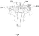
Fig. 9 is a stereo sectional view of the compressor ofFig. 5 . - Firstly, the equivalent mass of a leaf spring is explained as follows:
In the spring vibration system as shown inFig. 1 , let the mass of the spring be ms , the length of the spring in static balance be l, and the displacement of the end of the spring in vibration be u(t). According to a conclusion in material mechanics that the static tension/compression displacement of a straight rod has a linear distribution, it can be considered that the vibration displacement of the spring also has a linear distribution, so the displacement of the spring's cross-section with a coordinate x is


- As can be known from the above, the equivalent mass of the leaf spring is determined by the actual structure of the leaf spring, i.e., by the inherent frequency and the axial rigidity of the leaf spring. It is preferable that the ratio of the equivalent mass mE of the leaf spring to the mass ms of the leaf spring is as small as possible. The ratio for the leaf spring in the prior art, which comprises concentric vortex arms with the equal arm width, is about 50%, whereas the ratio for the leaf spring comprising eccentric vortex arms is larger. The present invention aims at reducing the ratio mE /ms to the range from 25% to 50% by reducing the relative material amount in the intermediate region of the leaf spring.
- As shown in
Figs. 2-4 , the present disclosure provides a leaf spring, comprising at least two spring arms and an inner fixing hole. All spring arms are evenly distributed around a center of the inner fixing hole. Each spring arm is of the same structure, and an outer fixing hole is provided at an outermost end of each spring arm. - Preferably, the number of the spring arms may be two or three; the leaf spring may be a spring having equal or unequal arm width; the spring arm may be contoured with circular arcs or vortex lines; which will be respectively described below:
-
Fig. 2 illustrates the leaf spring according to the first example. The leaf spring comprises multiple concentric circular arms with equal arm width. Theleaf spring 100 comprises theinner fixing hole 110, thespring arms spring arms inner fixing hole 110. Thespring arms leaf spring 100 will be illustrated with reference to thespring arm 120 as follows:
Theouter fixing hole 122 is disposed in thespring arm 120 to fix theleaf spring 100. Thespring arm 120 is contoured by multiple pairs of concentric circular arcs, wherein adjacent circular arcs are tangent to each other. As shown inFig. 2 , from inside to outside, radii of the multiple pairs of concentric circular arcs gradually increase, for example, from 1 mm to 500 mm. The tail end of thespring arm 120 is contoured by thecircular arc 124 and the pair of concentric circular arcs with the largest radii, and the circular arc is tangent to both of the concentric circular arcs. Thecircular arc 124 and theouter fixing hole 122 are concentric, and the diameter of thecircular arc 124 is equal to the arm width of the spring arm 120 (the radius difference between the radii of each pair of concentric circular arcs forms the arm width of the spring arm). In this embodiment, the arm width of thespring arm 120 is constant. Preferably, the arm width of thespring arm 120 is ranged from 5 mm to 50 mm, and the thickness of theleaf spring 100 is ranged from 0.1 mm to 5 mm, so the ratio of the largest outer radius to the thickness is ranged from 5 to 5000. -
Fig. 3 illustrates the leaf spring according to the second example. The leaf spring comprises multiple concentric circular arms with unequal arm width. Theleaf spring 200 comprises theinner fixing hole 210, thespring arms 220and 230. Thespring arms inner fixing hole 210. Thespring arms leaf spring 200 will be illustrated with reference to thespring arm 220 as follows:
Theouter fixing hole 222 is disposed in thespring arm 220 to fix theleaf spring 200. Thespring arm 220 is contoured by multiple pairs of concentric circular arcs, wherein adjacent circular arcs are tangent to each other. As shown inFig. 3 , from inside to outside, radii of the multiple pairs of concentric circular arcs gradually increase, for example, from 1 mm to 500 mm. The tail end of thespring arm 220 is contoured by thecircular arc 224 and the pair of concentric circular arcs with the largest radii, and the circular arc is tangent to both of the pair of concentric circular arcs. Thecircular arc 224 and theouter fixing hole 222 are concentric. The arm width of thespring arm 220 is not constant and increases gradually from inside to outside. The ratio of the maximum arm width to the minimum arm width is greater than 1, and less than or equals to 10. Preferably, the arm width of thespring arm 220 is ranged from 5 mm to 50 mm, the thickness of theleaf spring 100 is ranged from 0.1 mm to 5 mm, so the ratio of the largest outer radius to the thickness is ranged from 5 to 5000. -
Fig. 4 illustrates the leaf spring according to the first embodiment of the present invention. The leaf spring comprises concentric vortex arms with unequal arm width. Theleaf spring 300 comprises theinner fixing hole 310 and thespring arms inner fixing hole 310. Thespring arms leaf spring 300 will be illustrated with reference to thespring arm 320 as follows:
Theouter fixing hole 322 is disposed in thespring arm 320. Thespring arm 320 is contoured by two concentric vortex lines, namely, thefirst vortex line 324 and thesecond vortex line 326. The start end of thespring arm 320 is contoured by connecting the start ends of thefirst vortex line 324 and thesecond vortex line 326 with the circular arcs which are concentric with theinner fixing hole 310. Preferably, thefirst vortex line 324 is connected, via a firstcircular arc 328, to a circular arc which is concentric with theinner fixing hole 310. Two ends of the firstcircular arc 328 are respectively tangent to the start end of thefirst vortex line 324 and the circular arc which is concentric with theinner fixing hole 310. Thesecond vortex line 326 is connected, via a secondcircular arc 329, to the circular arc which is concentric with theinner fixing hole 310. Two ends of the secondcircular arc 329 are respectively tangent to the start end of the second vortex line and the circular arc which is concentric with theinner fixing hole 310. The tail end of thespring arm 320 is contoured by two or three segments of circular arcs and thevortex lines circular arc 327 at the outermost tail end is concentric with the outer fixing hole. Thefirst vortex line 324 and thesecond vortex line 326 respectively meet the following equations:


- Wherein, X and Y are coordinate values, a and a+b are coefficients of radius, t is a variable, α is an initial angle, and 0.5≤a≤30, 0≤b≤10, 0 rad<t≤30 rad, and 0 rad<α≤150 rad.
- As shown in
Fig. 4 , the arm width of thespring arm 320 increases gradually from inside to outside, and the ratio of the maximum arm width to the minimum arm width is greater than 1, and less than or equals to 10. The thickness of theleaf spring 300 is ranged from 0.1 mm to 5 mm, so the ratio of the largest outer radius to the thickness is ranged from 5 to 5000. - The leaf spring provided by the present disclosure has a structure of multiple concentric circular arms or a structure of concentric vortex arms, and the leaf spring has smaller equivalent mass (25% ∼ 50%), so that the rigidity and the inherent frequency requirements are met without the need of increasing mass of the components, thereby reducing the product mass and saving the cost. What's more, under the conditions of the same outer radius, the leaf spring with the structure of the present disclosure has a larger linear working range, which is beneficial for making the leaf spring compact in structure.
- The present disclosure further provides a
leaf spring group 000, which comprises at least two leaf springs mentioned above. Multiple leaf springs mentioned above are stacked together, which can enhance the rigidity between the components which move relatively to each other. Preferably,gaskets 400 are arranged between two adjacent leaf springs. - As shown in
Fig.5-9 , the present invention further provides a compressor, which comprises theleaf spring group 000 above. Thegaskets 400 with certain thickness and shape are arranged between the leaf springs of theleaf spring group 000. Preferably, thegasket 400 is arranged at the position where the leaf spring group is fixed. On one hand, thegaskets 400 reduce the concentrated stress acting on the position where theleaf spring group 000 is fixed; on the other hand, the gaskets prevent the friction and abrasion between adjacent leaf springs, and prolong the service life of theleaf spring group 000. - What described above are several embodiments of the present invention, and they are specific and in details, but not intended to limit the scope of the present invention. It will be understood by those skilled in the art that various modifications and improvements can be made without departing from the conception of the present disclosure, and all these modifications and improvements are within the scope of the present invention. Therefore, the scope of the present invention should be subject to the claims attached.
Claims (7)
- A leaf spring (100; 200; 300), comprising at least two spring arms (120, 130; 220, 230; 320, 330, 340) and an inner fixing hole (110; 210; 310); the at least two spring arms are evenly distributed around a center of the inner fixing hole; each spring arm is of same structure; and an outer fixing hole (122; 222; 322) is disposed at an outermost end of each spring arm; characterized in that:each spring arm (120, 130; 220, 230; 320, 330, 340) is contoured by two concentric vortex lines, that is, a first vortex line (324) and a second vortex line (326); a start end of the spring arm is contoured by connecting start ends of the first vortex line (324) and the second vortex line (326) with circular arcs which are concentric with the inner fixing hole (310); a tail end of the spring arm (320) is contoured by two or three segments of circular arcs and two concentric vortex lines (324, 326), and the segments of circular arcs are tangent to the two concentric vortex lines; and a circular arc (327) at the outermost tail end is concentric with the outer fixing hole;the two concentric vortex lines (324, 326) respectively meet equations:


and

- The leaf spring (300) according to claim 1, characterized in that, via a first circular arc (328) and a second circular arc (329), start ends of the two concentric vortex lines are respectively connected to the circular arc which is concentric with the inner fixing hole (310); two ends of the first circular arc (328) are respectively tangent to the first vortex line (324) and the circular arc which is concentric with the inner fixing hole (310); and two ends of the second circular arc (329) are respectively tangent to the second vortex line (326) and the circular arc which is concentric with the inner fixing hole (310).
- The leaf spring (100; 200; 300) according to any one of the preceding claims, characterized in that, a thickness of the leaf spring (100; 200; 300) is ranged from 0.1mm to 5mm; and a ratio of the largest outer radius to the thickness is ranged from 5 to 5000.
- The leaf spring (100) according to claim 1, characterized in that, an arm width of each spring arm (120, 130) is constant.
- The leaf spring (200) according to claim 1, characterized in that, an arm width of each spring arm (220, 230) increases gradually from inside to outside; and a ratio of maximum arm width to minimum arm width is greater than 1, and less than or equals to 10.
- A leaf spring group (000), comprising at least two leaf springs (100; 200; 300) as defined in any one of claims 1-5, characterized in that, a gasket (400) is arranged between the leaf springs (100; 200; 300).
- A compressor, comprising the leaf spring group (000) as defined in claim 6.
Applications Claiming Priority (2)
| Application Number | Priority Date | Filing Date | Title |
|---|---|---|---|
| CN201310459756.8A CN104514828B (en) | 2013-09-30 | 2013-09-30 | Flat spring and plate spring groups and compressor |
| PCT/CN2014/086056 WO2015043371A1 (en) | 2013-09-30 | 2014-09-05 | Leaf spring, leaf spring group, and compressor |
Publications (3)
| Publication Number | Publication Date |
|---|---|
| EP3054188A1 EP3054188A1 (en) | 2016-08-10 |
| EP3054188A4 EP3054188A4 (en) | 2016-11-02 |
| EP3054188B1 true EP3054188B1 (en) | 2019-07-31 |
Family
ID=52742019
Family Applications (1)
| Application Number | Title | Priority Date | Filing Date |
|---|---|---|---|
| EP14847938.9A Active EP3054188B1 (en) | 2013-09-30 | 2014-09-05 | Leaf spring, leaf spring group, and compressor |
Country Status (6)
| Country | Link |
|---|---|
| US (1) | US9810278B2 (en) |
| EP (1) | EP3054188B1 (en) |
| JP (1) | JP6663853B2 (en) |
| KR (1) | KR102004888B1 (en) |
| CN (1) | CN104514828B (en) |
| WO (1) | WO2015043371A1 (en) |
Families Citing this family (29)
| Publication number | Priority date | Publication date | Assignee | Title |
|---|---|---|---|---|
| US20160102724A1 (en) * | 2014-10-09 | 2016-04-14 | Rethink Motion Inc. | Concentric Arc Spline Rotational Spring |
| US10364858B2 (en) * | 2015-07-23 | 2019-07-30 | Rethink Robotics Gmbh | Planar flexure members and actuators using them |
| WO2017028004A1 (en) * | 2015-08-14 | 2017-02-23 | 海能达通信股份有限公司 | Carrying clip for electronic device |
| CN105134553B (en) * | 2015-08-25 | 2018-06-26 | 同济大学 | The flat spring and the compressor using the flat spring of linear springs arm and its composition |
| CN105179540B (en) * | 2015-08-25 | 2018-06-26 | 同济大学 | The flat spring and the compressor using the flat spring of fan-shaped spring arm and its composition |
| CN106224419B (en) * | 2016-08-19 | 2018-06-12 | 珠海格力节能环保制冷技术研究中心有限公司 | Flat spring and compressor |
| CN106777796B (en) * | 2017-01-12 | 2019-09-03 | 山东理工大学 | Matching Method of Stiffness and Contact Load of Three-stage Gradient Leaf Spring in Vehicle Suspension |
| FR3074620B1 (en) * | 2017-12-05 | 2019-10-25 | Ams R&D Sas | ELECTRIC MOTOR |
| CN108194547B (en) * | 2017-12-28 | 2024-02-13 | 陕西仙童科技有限公司 | Flexible springs, flexible spring groups and compressors |
| CN108194548B (en) * | 2017-12-28 | 2023-12-29 | 陕西仙童科技有限公司 | Plate spring, plate spring set and compressor |
| DE102018102758B4 (en) * | 2018-02-07 | 2020-01-16 | Kendrion (Villingen) Gmbh | Spring for a check valve, check valve with such a spring, controllable vibration damper with such a check valve and motor vehicle with such a controllable vibration damper |
| CN108194561A (en) * | 2018-02-22 | 2018-06-22 | 方舟 | A kind of acoustic energy refrigeration machine and its damper |
| JP7401517B2 (en) * | 2018-03-28 | 2023-12-19 | ロボリジェント インコーポレイテッド | Torsional series elastic actuator |
| DE102019121225A1 (en) * | 2019-08-06 | 2021-02-11 | DÜRR Technik GmbH & Co. KG | Linear compressor or linear pump |
| DE102019121227A1 (en) * | 2019-08-06 | 2021-02-11 | Dürr Technik GmbH & Co.KG | Linear compressor or linear pump |
| CN111043234A (en) * | 2019-11-18 | 2020-04-21 | 上海厚酷科技有限公司 | Vibration absorber |
| CN111043214A (en) * | 2019-11-18 | 2020-04-21 | 上海厚酷科技有限公司 | Shock absorption system of refrigerating machine |
| EP4115095A1 (en) * | 2020-03-03 | 2023-01-11 | FM Energie GmbH & Co. KG | Frequency-adaptive leaf-spring tuned mass damper |
| CN113669397B (en) * | 2020-05-14 | 2022-09-30 | 同济大学 | A connecting reed and leaf spring |
| CN113757282A (en) * | 2020-06-05 | 2021-12-07 | 中国科学院理化技术研究所 | Leaf spring |
| RU203373U1 (en) * | 2020-08-04 | 2021-04-01 | Федеральное государственное бюджетное образовательное учреждение высшего образования "Самарский государственный университет путей сообщения" (СамГУПС) | PLATE VIBRATION ISOLATOR |
| KR102436042B1 (en) * | 2020-12-18 | 2022-08-24 | 엘지전자 주식회사 | Elastic body and linear compressor including the same |
| CN115143216B (en) * | 2021-03-29 | 2024-09-24 | 中国科学院理化技术研究所 | Curved beam arm plate spring, elastic support piece and compressor |
| CN115126809B (en) * | 2021-03-29 | 2024-07-02 | 中国科学院理化技术研究所 | Leaf spring, leaf spring group, motor and vibration damper |
| CN115146397B (en) * | 2021-03-29 | 2025-01-21 | 中国科学院理化技术研究所 | Leaf spring and its swing arm shape determination method |
| CN116006608B (en) * | 2021-10-22 | 2025-01-14 | 中国科学院理化技术研究所 | Leaf spring assembly, linear motor and linear compressor |
| US11680660B2 (en) * | 2021-11-09 | 2023-06-20 | Raytheon Company | Ball valve handle, spring loaded |
| US12092092B2 (en) | 2022-01-04 | 2024-09-17 | Haier Us Appliance Solutions, Inc. | Linear compressor and planar spring assembly |
| CN115717634B (en) * | 2022-11-21 | 2025-07-29 | 国家电网有限公司 | Variable force rolling plate spring for tower climbing unpowered exoskeleton joint |
Family Cites Families (24)
| Publication number | Priority date | Publication date | Assignee | Title |
|---|---|---|---|---|
| US5351490A (en) * | 1992-01-31 | 1994-10-04 | Mitsubishi Denki Kabushiki Kaisha | Piston/displacer support means for a cryogenic refrigerator |
| US5522214A (en) * | 1993-07-30 | 1996-06-04 | Stirling Technology Company | Flexure bearing support, with particular application to stirling machines |
| US5525845A (en) * | 1994-03-21 | 1996-06-11 | Sunpower, Inc. | Fluid bearing with compliant linkage for centering reciprocating bodies |
| JP3656312B2 (en) * | 1996-03-19 | 2005-06-08 | 富士電機システムズ株式会社 | Suspension spring unit for refrigerator |
| JP3700740B2 (en) * | 1997-03-10 | 2005-09-28 | アイシン精機株式会社 | Flexure bearing for linear motor driven compressor |
| US6056519A (en) * | 1997-10-15 | 2000-05-02 | Matsushita Refrigeration Company | Structure of vibrating compressor |
| JP2000120536A (en) * | 1998-10-15 | 2000-04-25 | Matsushita Refrig Co Ltd | Oscillatory type compressor |
| JP2001304316A (en) * | 2000-04-20 | 2001-10-31 | Sanyo Electric Co Ltd | Suspension spring |
| JP3512371B2 (en) * | 2000-06-19 | 2004-03-29 | 松下電器産業株式会社 | Linear compressor |
| JP2003247580A (en) * | 2002-02-26 | 2003-09-05 | Sharp Corp | Flat spring, linear motor compressor and Stirling engine |
| JP4273737B2 (en) * | 2002-10-16 | 2009-06-03 | パナソニック株式会社 | Linear motor and linear compressor |
| AU2003301464A1 (en) * | 2002-10-16 | 2004-05-04 | Matsushita Refrigeration Company | Linear motor and liner compressor using the same |
| KR100512748B1 (en) * | 2003-12-18 | 2005-09-07 | 삼성전자주식회사 | Linear compressor |
| CN2675950Y (en) | 2004-03-08 | 2005-02-02 | 李岳 | Disc torsion combined spring |
| JP3772179B2 (en) * | 2004-08-02 | 2006-05-10 | シャープ株式会社 | Vibration suppression device and Stirling engine equipped with the same |
| GB0417611D0 (en) * | 2004-08-06 | 2004-09-08 | Microgen Energy Ltd | A linear free piston stirling machine |
| JP2006275178A (en) * | 2005-03-29 | 2006-10-12 | Sanden Corp | Electromagnetic clutch |
| JP4629601B2 (en) * | 2006-03-22 | 2011-02-09 | ツインバード工業株式会社 | Spring device |
| CN201198826Y (en) | 2007-12-28 | 2009-02-25 | 中国航天科技集团公司第五研究院第五一〇研究所 | A leaf spring box assembly |
| CN101892971B (en) * | 2010-08-06 | 2012-05-16 | 浙江大学 | Linear compressor of plate spring supporting system adopting two different types of lines |
| FR2993035B1 (en) * | 2012-07-05 | 2015-02-20 | Asco Joucomatic Sa | FLAT CORE TYPE SOLENOID VALVE AND FLAT SPRING. |
| CN103256203B (en) * | 2013-04-17 | 2015-07-29 | 浙江大学 | A kind of air-conditioning refrigerator Linearkompressor |
| US8960655B2 (en) * | 2013-05-31 | 2015-02-24 | Sunpower, Inc. | Compact flexure bearing spring for springing multiple bodies |
| US20160102724A1 (en) * | 2014-10-09 | 2016-04-14 | Rethink Motion Inc. | Concentric Arc Spline Rotational Spring |
-
2013
- 2013-09-30 CN CN201310459756.8A patent/CN104514828B/en active Active
-
2014
- 2014-09-05 KR KR1020167011414A patent/KR102004888B1/en active Active
- 2014-09-05 JP JP2016544708A patent/JP6663853B2/en active Active
- 2014-09-05 WO PCT/CN2014/086056 patent/WO2015043371A1/en not_active Ceased
- 2014-09-05 EP EP14847938.9A patent/EP3054188B1/en active Active
- 2014-09-05 US US15/026,012 patent/US9810278B2/en active Active
Non-Patent Citations (1)
| Title |
|---|
| None * |
Also Published As
| Publication number | Publication date |
|---|---|
| EP3054188A4 (en) | 2016-11-02 |
| JP2016537592A (en) | 2016-12-01 |
| CN104514828A (en) | 2015-04-15 |
| EP3054188A1 (en) | 2016-08-10 |
| KR20160097190A (en) | 2016-08-17 |
| WO2015043371A1 (en) | 2015-04-02 |
| JP6663853B2 (en) | 2020-03-13 |
| CN104514828B (en) | 2016-06-08 |
| US9810278B2 (en) | 2017-11-07 |
| KR102004888B1 (en) | 2019-07-29 |
| US20160290427A1 (en) | 2016-10-06 |
Similar Documents
| Publication | Publication Date | Title |
|---|---|---|
| EP3054188A1 (en) | Leaf spring, leaf spring group, and compressor | |
| US20140008557A1 (en) | Solenoid valve with flat core and flat spring | |
| AU626188B2 (en) | Coiled spring | |
| JP7316737B2 (en) | Pump body structure, compressor and heat exchange equipment | |
| CN111664207A (en) | A variable damping friction pair of a base metal shock absorber | |
| US8876095B2 (en) | Coil spring | |
| CN105757152A (en) | Plate spring, plate spring set and compressor | |
| CN107850213A (en) | Compression ring with odd-shaped cross section | |
| CN111173871B (en) | Rigidity-adjustable large-flexibility torsion spring for steering engine loading | |
| US20170335919A1 (en) | Damping Valve For A Vibration Damper | |
| CN109519498A (en) | SMA Self-resetting becomes friction damping device | |
| KR20200037433A (en) | Torsional vibration damper with nonuniform elastomer profile | |
| CN104632885A (en) | Rubber elastic bearing | |
| CN103343797B (en) | A kind of damping unit | |
| CN112096741B (en) | Gas bearings | |
| CN103291750B (en) | The elastic foil gas bearing that a kind of pretension is adjustable | |
| CN204357997U (en) | Leaf spring, plate spring groups and compressor | |
| CN110499676B (en) | Local resonance type supporting structure for floating slab track | |
| CN212775298U (en) | Variable damping friction pair of base type metal shock absorber | |
| EP3269998B1 (en) | Holed and spherical hinge type rubber elastic element | |
| CN109654117A (en) | A kind of two-way compression-resistant type bearing | |
| CN102913323B (en) | Heavy-load crank-link mechanism | |
| CN218581707U (en) | M-shaped lightweight piston and engine | |
| CN216691977U (en) | Piston assembly for air spring, air spring and vehicle | |
| CN205896455U (en) | Bellows and adopt oil pipe that adds of this bellows |
Legal Events
| Date | Code | Title | Description |
|---|---|---|---|
| PUAI | Public reference made under article 153(3) epc to a published international application that has entered the european phase |
Free format text: ORIGINAL CODE: 0009012 |
|
| 17P | Request for examination filed |
Effective date: 20160330 |
|
| AK | Designated contracting states |
Kind code of ref document: A1 Designated state(s): AL AT BE BG CH CY CZ DE DK EE ES FI FR GB GR HR HU IE IS IT LI LT LU LV MC MK MT NL NO PL PT RO RS SE SI SK SM TR |
|
| AX | Request for extension of the european patent |
Extension state: BA ME |
|
| A4 | Supplementary search report drawn up and despatched |
Effective date: 20161006 |
|
| RIC1 | Information provided on ipc code assigned before grant |
Ipc: F16F 1/32 20060101AFI20160929BHEP Ipc: F16F 3/00 20060101ALI20160929BHEP Ipc: F16F 1/02 20060101ALI20160929BHEP |
|
| DAX | Request for extension of the european patent (deleted) | ||
| REG | Reference to a national code |
Ref country code: DE Ref legal event code: R079 Ref document number: 602014051017 Country of ref document: DE Free format text: PREVIOUS MAIN CLASS: F16F0001320000 Ipc: F16F0001180000 |
|
| GRAP | Despatch of communication of intention to grant a patent |
Free format text: ORIGINAL CODE: EPIDOSNIGR1 |
|
| STAA | Information on the status of an ep patent application or granted ep patent |
Free format text: STATUS: GRANT OF PATENT IS INTENDED |
|
| RIC1 | Information provided on ipc code assigned before grant |
Ipc: F16F 1/02 20060101ALI20190312BHEP Ipc: F16F 1/18 20060101AFI20190312BHEP Ipc: F16F 3/02 20060101ALI20190312BHEP Ipc: F16F 3/00 20060101ALI20190312BHEP |
|
| INTG | Intention to grant announced |
Effective date: 20190415 |
|
| GRAS | Grant fee paid |
Free format text: ORIGINAL CODE: EPIDOSNIGR3 |
|
| GRAA | (expected) grant |
Free format text: ORIGINAL CODE: 0009210 |
|
| STAA | Information on the status of an ep patent application or granted ep patent |
Free format text: STATUS: THE PATENT HAS BEEN GRANTED |
|
| AK | Designated contracting states |
Kind code of ref document: B1 Designated state(s): AL AT BE BG CH CY CZ DE DK EE ES FI FR GB GR HR HU IE IS IT LI LT LU LV MC MK MT NL NO PL PT RO RS SE SI SK SM TR |
|
| REG | Reference to a national code |
Ref country code: CH Ref legal event code: EP Ref country code: GB Ref legal event code: FG4D |
|
| REG | Reference to a national code |
Ref country code: AT Ref legal event code: REF Ref document number: 1161223 Country of ref document: AT Kind code of ref document: T Effective date: 20190815 |
|
| REG | Reference to a national code |
Ref country code: IE Ref legal event code: FG4D |
|
| REG | Reference to a national code |
Ref country code: DE Ref legal event code: R096 Ref document number: 602014051017 Country of ref document: DE |
|
| REG | Reference to a national code |
Ref country code: NL Ref legal event code: MP Effective date: 20190731 |
|
| REG | Reference to a national code |
Ref country code: LT Ref legal event code: MG4D |
|
| REG | Reference to a national code |
Ref country code: AT Ref legal event code: MK05 Ref document number: 1161223 Country of ref document: AT Kind code of ref document: T Effective date: 20190731 |
|
| PG25 | Lapsed in a contracting state [announced via postgrant information from national office to epo] |
Ref country code: FI Free format text: LAPSE BECAUSE OF FAILURE TO SUBMIT A TRANSLATION OF THE DESCRIPTION OR TO PAY THE FEE WITHIN THE PRESCRIBED TIME-LIMIT Effective date: 20190731 Ref country code: HR Free format text: LAPSE BECAUSE OF FAILURE TO SUBMIT A TRANSLATION OF THE DESCRIPTION OR TO PAY THE FEE WITHIN THE PRESCRIBED TIME-LIMIT Effective date: 20190731 Ref country code: SE Free format text: LAPSE BECAUSE OF FAILURE TO SUBMIT A TRANSLATION OF THE DESCRIPTION OR TO PAY THE FEE WITHIN THE PRESCRIBED TIME-LIMIT Effective date: 20190731 Ref country code: BG Free format text: LAPSE BECAUSE OF FAILURE TO SUBMIT A TRANSLATION OF THE DESCRIPTION OR TO PAY THE FEE WITHIN THE PRESCRIBED TIME-LIMIT Effective date: 20191031 Ref country code: NO Free format text: LAPSE BECAUSE OF FAILURE TO SUBMIT A TRANSLATION OF THE DESCRIPTION OR TO PAY THE FEE WITHIN THE PRESCRIBED TIME-LIMIT Effective date: 20191031 Ref country code: NL Free format text: LAPSE BECAUSE OF FAILURE TO SUBMIT A TRANSLATION OF THE DESCRIPTION OR TO PAY THE FEE WITHIN THE PRESCRIBED TIME-LIMIT Effective date: 20190731 Ref country code: LT Free format text: LAPSE BECAUSE OF FAILURE TO SUBMIT A TRANSLATION OF THE DESCRIPTION OR TO PAY THE FEE WITHIN THE PRESCRIBED TIME-LIMIT Effective date: 20190731 Ref country code: AT Free format text: LAPSE BECAUSE OF FAILURE TO SUBMIT A TRANSLATION OF THE DESCRIPTION OR TO PAY THE FEE WITHIN THE PRESCRIBED TIME-LIMIT Effective date: 20190731 Ref country code: PT Free format text: LAPSE BECAUSE OF FAILURE TO SUBMIT A TRANSLATION OF THE DESCRIPTION OR TO PAY THE FEE WITHIN THE PRESCRIBED TIME-LIMIT Effective date: 20191202 |
|
| PG25 | Lapsed in a contracting state [announced via postgrant information from national office to epo] |
Ref country code: IS Free format text: LAPSE BECAUSE OF FAILURE TO SUBMIT A TRANSLATION OF THE DESCRIPTION OR TO PAY THE FEE WITHIN THE PRESCRIBED TIME-LIMIT Effective date: 20191130 Ref country code: GR Free format text: LAPSE BECAUSE OF FAILURE TO SUBMIT A TRANSLATION OF THE DESCRIPTION OR TO PAY THE FEE WITHIN THE PRESCRIBED TIME-LIMIT Effective date: 20191101 Ref country code: ES Free format text: LAPSE BECAUSE OF FAILURE TO SUBMIT A TRANSLATION OF THE DESCRIPTION OR TO PAY THE FEE WITHIN THE PRESCRIBED TIME-LIMIT Effective date: 20190731 Ref country code: AL Free format text: LAPSE BECAUSE OF FAILURE TO SUBMIT A TRANSLATION OF THE DESCRIPTION OR TO PAY THE FEE WITHIN THE PRESCRIBED TIME-LIMIT Effective date: 20190731 Ref country code: LV Free format text: LAPSE BECAUSE OF FAILURE TO SUBMIT A TRANSLATION OF THE DESCRIPTION OR TO PAY THE FEE WITHIN THE PRESCRIBED TIME-LIMIT Effective date: 20190731 Ref country code: RS Free format text: LAPSE BECAUSE OF FAILURE TO SUBMIT A TRANSLATION OF THE DESCRIPTION OR TO PAY THE FEE WITHIN THE PRESCRIBED TIME-LIMIT Effective date: 20190731 |
|
| PG25 | Lapsed in a contracting state [announced via postgrant information from national office to epo] |
Ref country code: TR Free format text: LAPSE BECAUSE OF FAILURE TO SUBMIT A TRANSLATION OF THE DESCRIPTION OR TO PAY THE FEE WITHIN THE PRESCRIBED TIME-LIMIT Effective date: 20190731 |
|
| PG25 | Lapsed in a contracting state [announced via postgrant information from national office to epo] |
Ref country code: EE Free format text: LAPSE BECAUSE OF FAILURE TO SUBMIT A TRANSLATION OF THE DESCRIPTION OR TO PAY THE FEE WITHIN THE PRESCRIBED TIME-LIMIT Effective date: 20190731 Ref country code: PL Free format text: LAPSE BECAUSE OF FAILURE TO SUBMIT A TRANSLATION OF THE DESCRIPTION OR TO PAY THE FEE WITHIN THE PRESCRIBED TIME-LIMIT Effective date: 20190731 Ref country code: IT Free format text: LAPSE BECAUSE OF FAILURE TO SUBMIT A TRANSLATION OF THE DESCRIPTION OR TO PAY THE FEE WITHIN THE PRESCRIBED TIME-LIMIT Effective date: 20190731 Ref country code: RO Free format text: LAPSE BECAUSE OF FAILURE TO SUBMIT A TRANSLATION OF THE DESCRIPTION OR TO PAY THE FEE WITHIN THE PRESCRIBED TIME-LIMIT Effective date: 20190731 Ref country code: DK Free format text: LAPSE BECAUSE OF FAILURE TO SUBMIT A TRANSLATION OF THE DESCRIPTION OR TO PAY THE FEE WITHIN THE PRESCRIBED TIME-LIMIT Effective date: 20190731 |
|
| PG25 | Lapsed in a contracting state [announced via postgrant information from national office to epo] |
Ref country code: CZ Free format text: LAPSE BECAUSE OF FAILURE TO SUBMIT A TRANSLATION OF THE DESCRIPTION OR TO PAY THE FEE WITHIN THE PRESCRIBED TIME-LIMIT Effective date: 20190731 Ref country code: SK Free format text: LAPSE BECAUSE OF FAILURE TO SUBMIT A TRANSLATION OF THE DESCRIPTION OR TO PAY THE FEE WITHIN THE PRESCRIBED TIME-LIMIT Effective date: 20190731 Ref country code: SM Free format text: LAPSE BECAUSE OF FAILURE TO SUBMIT A TRANSLATION OF THE DESCRIPTION OR TO PAY THE FEE WITHIN THE PRESCRIBED TIME-LIMIT Effective date: 20190731 Ref country code: IS Free format text: LAPSE BECAUSE OF FAILURE TO SUBMIT A TRANSLATION OF THE DESCRIPTION OR TO PAY THE FEE WITHIN THE PRESCRIBED TIME-LIMIT Effective date: 20200224 Ref country code: MC Free format text: LAPSE BECAUSE OF FAILURE TO SUBMIT A TRANSLATION OF THE DESCRIPTION OR TO PAY THE FEE WITHIN THE PRESCRIBED TIME-LIMIT Effective date: 20190731 |
|
| REG | Reference to a national code |
Ref country code: CH Ref legal event code: PL |
|
| REG | Reference to a national code |
Ref country code: DE Ref legal event code: R097 Ref document number: 602014051017 Country of ref document: DE |
|
| PLBE | No opposition filed within time limit |
Free format text: ORIGINAL CODE: 0009261 |
|
| STAA | Information on the status of an ep patent application or granted ep patent |
Free format text: STATUS: NO OPPOSITION FILED WITHIN TIME LIMIT |
|
| PG2D | Information on lapse in contracting state deleted |
Ref country code: IS |
|
| PG25 | Lapsed in a contracting state [announced via postgrant information from national office to epo] |
Ref country code: CH Free format text: LAPSE BECAUSE OF NON-PAYMENT OF DUE FEES Effective date: 20190930 Ref country code: LU Free format text: LAPSE BECAUSE OF NON-PAYMENT OF DUE FEES Effective date: 20190905 Ref country code: IE Free format text: LAPSE BECAUSE OF NON-PAYMENT OF DUE FEES Effective date: 20190905 Ref country code: LI Free format text: LAPSE BECAUSE OF NON-PAYMENT OF DUE FEES Effective date: 20190930 Ref country code: IS Free format text: LAPSE BECAUSE OF FAILURE TO SUBMIT A TRANSLATION OF THE DESCRIPTION OR TO PAY THE FEE WITHIN THE PRESCRIBED TIME-LIMIT Effective date: 20191030 |
|
| REG | Reference to a national code |
Ref country code: BE Ref legal event code: MM Effective date: 20190930 |
|
| 26N | No opposition filed |
Effective date: 20200603 |
|
| PG25 | Lapsed in a contracting state [announced via postgrant information from national office to epo] |
Ref country code: SI Free format text: LAPSE BECAUSE OF FAILURE TO SUBMIT A TRANSLATION OF THE DESCRIPTION OR TO PAY THE FEE WITHIN THE PRESCRIBED TIME-LIMIT Effective date: 20190731 Ref country code: BE Free format text: LAPSE BECAUSE OF NON-PAYMENT OF DUE FEES Effective date: 20190930 |
|
| PG25 | Lapsed in a contracting state [announced via postgrant information from national office to epo] |
Ref country code: CY Free format text: LAPSE BECAUSE OF FAILURE TO SUBMIT A TRANSLATION OF THE DESCRIPTION OR TO PAY THE FEE WITHIN THE PRESCRIBED TIME-LIMIT Effective date: 20190731 |
|
| PG25 | Lapsed in a contracting state [announced via postgrant information from national office to epo] |
Ref country code: MT Free format text: LAPSE BECAUSE OF FAILURE TO SUBMIT A TRANSLATION OF THE DESCRIPTION OR TO PAY THE FEE WITHIN THE PRESCRIBED TIME-LIMIT Effective date: 20190731 Ref country code: HU Free format text: LAPSE BECAUSE OF FAILURE TO SUBMIT A TRANSLATION OF THE DESCRIPTION OR TO PAY THE FEE WITHIN THE PRESCRIBED TIME-LIMIT; INVALID AB INITIO Effective date: 20140905 |
|
| PG25 | Lapsed in a contracting state [announced via postgrant information from national office to epo] |
Ref country code: MK Free format text: LAPSE BECAUSE OF FAILURE TO SUBMIT A TRANSLATION OF THE DESCRIPTION OR TO PAY THE FEE WITHIN THE PRESCRIBED TIME-LIMIT Effective date: 20190731 |
|
| P01 | Opt-out of the competence of the unified patent court (upc) registered |
Effective date: 20230530 |
|
| PGFP | Annual fee paid to national office [announced via postgrant information from national office to epo] |
Ref country code: DE Payment date: 20250919 Year of fee payment: 12 |
|
| PGFP | Annual fee paid to national office [announced via postgrant information from national office to epo] |
Ref country code: GB Payment date: 20250811 Year of fee payment: 12 |
|
| PGFP | Annual fee paid to national office [announced via postgrant information from national office to epo] |
Ref country code: FR Payment date: 20250811 Year of fee payment: 12 |