EP3054169B1 - Stator blade assembly and gas turbine - Google Patents
Stator blade assembly and gas turbine Download PDFInfo
- Publication number
- EP3054169B1 EP3054169B1 EP16160027.5A EP16160027A EP3054169B1 EP 3054169 B1 EP3054169 B1 EP 3054169B1 EP 16160027 A EP16160027 A EP 16160027A EP 3054169 B1 EP3054169 B1 EP 3054169B1
- Authority
- EP
- European Patent Office
- Prior art keywords
- portions
- inner shroud
- springs
- shroud portions
- disposed
- Prior art date
- Legal status (The legal status is an assumption and is not a legal conclusion. Google has not performed a legal analysis and makes no representation as to the accuracy of the status listed.)
- Active
Links
- 238000013016 damping Methods 0.000 claims description 77
- 238000000034 method Methods 0.000 claims description 20
- 238000010586 diagram Methods 0.000 description 32
- 125000006850 spacer group Chemical group 0.000 description 31
- 239000012530 fluid Substances 0.000 description 20
- 238000003825 pressing Methods 0.000 description 15
- 230000005284 excitation Effects 0.000 description 9
- 230000006835 compression Effects 0.000 description 8
- 238000007906 compression Methods 0.000 description 8
- 239000000463 material Substances 0.000 description 7
- 230000002829 reductive effect Effects 0.000 description 6
- 238000007789 sealing Methods 0.000 description 6
- 238000003780 insertion Methods 0.000 description 5
- 230000037431 insertion Effects 0.000 description 5
- 230000007774 longterm Effects 0.000 description 4
- 238000011144 upstream manufacturing Methods 0.000 description 3
- 230000007423 decrease Effects 0.000 description 2
- 238000003754 machining Methods 0.000 description 2
- 230000036961 partial effect Effects 0.000 description 2
- 230000000149 penetrating effect Effects 0.000 description 2
- 230000002441 reversible effect Effects 0.000 description 2
- 230000003068 static effect Effects 0.000 description 2
- 230000015572 biosynthetic process Effects 0.000 description 1
- 238000005219 brazing Methods 0.000 description 1
- 239000002826 coolant Substances 0.000 description 1
- 230000003247 decreasing effect Effects 0.000 description 1
- 230000000694 effects Effects 0.000 description 1
- 239000000284 extract Substances 0.000 description 1
- 239000000446 fuel Substances 0.000 description 1
- 238000012423 maintenance Methods 0.000 description 1
- 238000003466 welding Methods 0.000 description 1
Images


Classifications
-
- F—MECHANICAL ENGINEERING; LIGHTING; HEATING; WEAPONS; BLASTING
- F01—MACHINES OR ENGINES IN GENERAL; ENGINE PLANTS IN GENERAL; STEAM ENGINES
- F01D—NON-POSITIVE DISPLACEMENT MACHINES OR ENGINES, e.g. STEAM TURBINES
- F01D5/00—Blades; Blade-carrying members; Heating, heat-insulating, cooling or antivibration means on the blades or the members
- F01D5/02—Blade-carrying members, e.g. rotors
-
- F—MECHANICAL ENGINEERING; LIGHTING; HEATING; WEAPONS; BLASTING
- F01—MACHINES OR ENGINES IN GENERAL; ENGINE PLANTS IN GENERAL; STEAM ENGINES
- F01D—NON-POSITIVE DISPLACEMENT MACHINES OR ENGINES, e.g. STEAM TURBINES
- F01D11/00—Preventing or minimising internal leakage of working-fluid, e.g. between stages
- F01D11/001—Preventing or minimising internal leakage of working-fluid, e.g. between stages for sealing space between stator blade and rotor
-
- F—MECHANICAL ENGINEERING; LIGHTING; HEATING; WEAPONS; BLASTING
- F01—MACHINES OR ENGINES IN GENERAL; ENGINE PLANTS IN GENERAL; STEAM ENGINES
- F01D—NON-POSITIVE DISPLACEMENT MACHINES OR ENGINES, e.g. STEAM TURBINES
- F01D11/00—Preventing or minimising internal leakage of working-fluid, e.g. between stages
- F01D11/02—Preventing or minimising internal leakage of working-fluid, e.g. between stages by non-contact sealings, e.g. of labyrinth type
-
- F—MECHANICAL ENGINEERING; LIGHTING; HEATING; WEAPONS; BLASTING
- F01—MACHINES OR ENGINES IN GENERAL; ENGINE PLANTS IN GENERAL; STEAM ENGINES
- F01D—NON-POSITIVE DISPLACEMENT MACHINES OR ENGINES, e.g. STEAM TURBINES
- F01D5/00—Blades; Blade-carrying members; Heating, heat-insulating, cooling or antivibration means on the blades or the members
- F01D5/02—Blade-carrying members, e.g. rotors
- F01D5/10—Anti- vibration means
-
- F—MECHANICAL ENGINEERING; LIGHTING; HEATING; WEAPONS; BLASTING
- F01—MACHINES OR ENGINES IN GENERAL; ENGINE PLANTS IN GENERAL; STEAM ENGINES
- F01D—NON-POSITIVE DISPLACEMENT MACHINES OR ENGINES, e.g. STEAM TURBINES
- F01D5/00—Blades; Blade-carrying members; Heating, heat-insulating, cooling or antivibration means on the blades or the members
- F01D5/12—Blades
- F01D5/14—Form or construction
- F01D5/16—Form or construction for counteracting blade vibration
-
- F—MECHANICAL ENGINEERING; LIGHTING; HEATING; WEAPONS; BLASTING
- F01—MACHINES OR ENGINES IN GENERAL; ENGINE PLANTS IN GENERAL; STEAM ENGINES
- F01D—NON-POSITIVE DISPLACEMENT MACHINES OR ENGINES, e.g. STEAM TURBINES
- F01D5/00—Blades; Blade-carrying members; Heating, heat-insulating, cooling or antivibration means on the blades or the members
- F01D5/12—Blades
- F01D5/26—Antivibration means not restricted to blade form or construction or to blade-to-blade connections or to the use of particular materials
-
- F—MECHANICAL ENGINEERING; LIGHTING; HEATING; WEAPONS; BLASTING
- F01—MACHINES OR ENGINES IN GENERAL; ENGINE PLANTS IN GENERAL; STEAM ENGINES
- F01D—NON-POSITIVE DISPLACEMENT MACHINES OR ENGINES, e.g. STEAM TURBINES
- F01D9/00—Stators
- F01D9/02—Nozzles; Nozzle boxes; Stator blades; Guide conduits, e.g. individual nozzles
-
- F—MECHANICAL ENGINEERING; LIGHTING; HEATING; WEAPONS; BLASTING
- F04—POSITIVE - DISPLACEMENT MACHINES FOR LIQUIDS; PUMPS FOR LIQUIDS OR ELASTIC FLUIDS
- F04D—NON-POSITIVE-DISPLACEMENT PUMPS
- F04D29/00—Details, component parts, or accessories
- F04D29/40—Casings; Connections of working fluid
- F04D29/52—Casings; Connections of working fluid for axial pumps
- F04D29/54—Fluid-guiding means, e.g. diffusers
- F04D29/541—Specially adapted for elastic fluid pumps
- F04D29/542—Bladed diffusers
-
- F—MECHANICAL ENGINEERING; LIGHTING; HEATING; WEAPONS; BLASTING
- F04—POSITIVE - DISPLACEMENT MACHINES FOR LIQUIDS; PUMPS FOR LIQUIDS OR ELASTIC FLUIDS
- F04D—NON-POSITIVE-DISPLACEMENT PUMPS
- F04D29/00—Details, component parts, or accessories
- F04D29/66—Combating cavitation, whirls, noise, vibration or the like; Balancing
- F04D29/661—Combating cavitation, whirls, noise, vibration or the like; Balancing especially adapted for elastic fluid pumps
- F04D29/668—Combating cavitation, whirls, noise, vibration or the like; Balancing especially adapted for elastic fluid pumps damping or preventing mechanical vibrations
-
- F—MECHANICAL ENGINEERING; LIGHTING; HEATING; WEAPONS; BLASTING
- F05—INDEXING SCHEMES RELATING TO ENGINES OR PUMPS IN VARIOUS SUBCLASSES OF CLASSES F01-F04
- F05D—INDEXING SCHEME FOR ASPECTS RELATING TO NON-POSITIVE-DISPLACEMENT MACHINES OR ENGINES, GAS-TURBINES OR JET-PROPULSION PLANTS
- F05D2250/00—Geometry
- F05D2250/10—Two-dimensional
- F05D2250/18—Two-dimensional patterned
- F05D2250/184—Two-dimensional patterned sinusoidal
-
- F—MECHANICAL ENGINEERING; LIGHTING; HEATING; WEAPONS; BLASTING
- F05—INDEXING SCHEMES RELATING TO ENGINES OR PUMPS IN VARIOUS SUBCLASSES OF CLASSES F01-F04
- F05D—INDEXING SCHEME FOR ASPECTS RELATING TO NON-POSITIVE-DISPLACEMENT MACHINES OR ENGINES, GAS-TURBINES OR JET-PROPULSION PLANTS
- F05D2250/00—Geometry
- F05D2250/60—Structure; Surface texture
- F05D2250/61—Structure; Surface texture corrugated
- F05D2250/611—Structure; Surface texture corrugated undulated
-
- F—MECHANICAL ENGINEERING; LIGHTING; HEATING; WEAPONS; BLASTING
- F05—INDEXING SCHEMES RELATING TO ENGINES OR PUMPS IN VARIOUS SUBCLASSES OF CLASSES F01-F04
- F05D—INDEXING SCHEME FOR ASPECTS RELATING TO NON-POSITIVE-DISPLACEMENT MACHINES OR ENGINES, GAS-TURBINES OR JET-PROPULSION PLANTS
- F05D2260/00—Function
- F05D2260/50—Kinematic linkage, i.e. transmission of position
- F05D2260/52—Kinematic linkage, i.e. transmission of position involving springs
-
- Y—GENERAL TAGGING OF NEW TECHNOLOGICAL DEVELOPMENTS; GENERAL TAGGING OF CROSS-SECTIONAL TECHNOLOGIES SPANNING OVER SEVERAL SECTIONS OF THE IPC; TECHNICAL SUBJECTS COVERED BY FORMER USPC CROSS-REFERENCE ART COLLECTIONS [XRACs] AND DIGESTS
- Y02—TECHNOLOGIES OR APPLICATIONS FOR MITIGATION OR ADAPTATION AGAINST CLIMATE CHANGE
- Y02T—CLIMATE CHANGE MITIGATION TECHNOLOGIES RELATED TO TRANSPORTATION
- Y02T50/00—Aeronautics or air transport
- Y02T50/60—Efficient propulsion technologies, e.g. for aircraft
Description
- The present invention relates to a gas turbine stator blade structure and gas turbines.
- Cantilever stator blades in which shrouds are provided as separate pieces, shrouded stator blades in which shrouds are integrally provided, and so on, are typically employed as stator blades of gas turbine compressors.
- With the shrouded stator blades, leakage of air, etc. is less likely to occur at tips of airfoil portions thereof as compared with the cantilever stator blades and, in addition, a rotor seal structure that suppresses leakage of air, etc. between the stator blades and the rotor can be provided at the inner circumferences of the shrouds. This allows the shrouded stator blades to reduce the air leakage level to an appropriate amount; therefore, they are considered advantageous in terms of performance.
- In the above-described shrouded stator blades, circumferential base portions referred to as shroud portions are provided at outer and inner end portions of the airfoil portions (profile portions).
- Examples of methods for securing the airfoil portions to the shroud portions include the tenon-type securing method, in which insertion portions protruding from the airfoil portions are inserted into insertion openings provided in the shroud portions, and the pork-chop-type securing method, in which insertion-flange portions formed in a widening shape from the airfoil portions are inserted into the above-described insertion openings.
- With the tenon-type securing method or the pork-chop-type securing method, the insertion portions or the insertion-flange portions may be secured by mechanically inserting them into the insertion openings, or they may be secured by brazing or welding. The shroud portions of the stator blades are assembled into a ring shape in this way.
- In addition, in some cases, the airfoil portions and the shroud portions are molded or machined as an integral structure.
- In order to absorb thermal expansion in the circumferential directions in a ring-shaped assembled state, to enhance the ease of machining and assembly of the shroud portions, and to achieve enhanced ease of maintenance for the shroud portions, etc., the shroud portions are typically divided into a plurality of portions in the circumferential direction. For example, in the case of the shrouded stator blades, the shroud portions are divided in correspondence with each stator blade.
- Furthermore, a seal structure, such as a labyrinth seal, a honeycomb seal or the like, is provided between the shroud portions and a rotating rotor shaft (for example, see
JP 2002-276304A - In consideration of the ease of machining or the ease of repairing, the configuration of the seal structure may be such that the seal structure is formed as a separate structure from the airfoil portions or the shroud portions, wherein the seal structure is combined with the airfoil portions or the shroud portions after being formed.
- In addition to the structure disclosed in
JP 2002-276304A - On the other hand, in a flow field of air or gas inside a compressor of a gas turbine, it is known that when stator blades receive an excitation force having a frequency matching the natural frequency of the stator blades or a frequency that is an integral multiple of the rotation speed, the airfoil portions and the shroud portions of the stator blades exhibit large vibrations (exhibit a vibration response).
- Examples of the above-described excitation force include the excitation force of a wake flow (wake) of rotating rotor blades, the excitation force of an interference flow (potential), and so forth.
- When the stress that acts on the stator blades caused by the above-described vibration response increases, exceeding the fatigue resistance of materials that constitute the stator blades, fatigue cracks may form in the stator blades, and the stator blades may be broken due to the fatigue cracks.
- Because of this, it is necessary to design the airfoil portions and the shroud portions so as to have physical-frame strength that prevents fatigue crack formation even if the vibration response occurs, and the natural frequency of the stator blades also needs to be shifted, in other words, detuned, from the excitation frequency that is expected to act on the stator blades.
- On the other hand, along with increases in output power, enhancement of performance, and reduction of costs in gas turbines in recent years, the size of profile portions is being increased, including enlargement of the blade profile width (blade chord), enlargement of the blade length (span), and so forth in the profile portions.
- When the profile portions are increased in size in this way, the aerodynamic force or force of gas that acts on the airfoil portions increases, and the load or moment that acts on base portions of the airfoil portions, in other words, connection portions between the airfoil portions and the shroud portions, increases. In order to endure such increases in load or moment, sufficient strength needs to be ensured by increasing the radial size of the radius of curvature R of fillets formed at the base portions of the airfoil portions.
- With regard to this, in contrast to ensuring sufficient strength at the base portions of the airfoil portions, there is a demand from an aerodynamic standpoint, that it is preferred to reduce the radial size of the radius of curvature R of the fillets formed at the base portions of the airfoil portions.
- The profile portions compress gas-containing air, etc. by being rotationally driven, and, on the other hand, receive air (containing gas) resistance in the flow field. Therefore, in order to decrease this air resistance, the profile shape is optimized, the leading-edge diameter and trailing-edge diameter in the profile portions are decreased in the radial sizes thereof, and the airfoil thickness itself is reduced.
- However, the above-described reduction of the radial size or thickness is a factor that decreases the strength of the stator blades, in particular the strength against a resonant response. Accordingly, with regard to designs of the profile portions, there are restrictions on the above-described reduction of the radial size or thickness in order to ensure the strength of the profile portions.
- In addition, in order to prevent the stator blades from breaking through resonating with the excitation force, the natural frequency of a stator-blade ring as a whole, in which a plurality of stator blades are combined, is shifted from the frequency of the excitation source; that is, detuning design is conducted so that the frequencies do not match.
- However, because the above-described natural frequency depends on the shape of the profile portions, the shape of the shroud portions, and so forth, when detuning between the natural frequency and the frequency of the excitation source is given priority, the stator blades in many cases are inevitably designed at the expense of the aerodynamic characteristics of the stator blades.
-
JP 2002-276304A - Furthermore, in order to reduce the vibration response in the stator blades, there is also a known technique for damping vibrations due to the vibration response in the stator blades by vibration damping (damping) which uses a frictional force using springs.
- More specifically, a known structure damps vibrations in the stator blades with a structure in which doughnut-ring shaped springs are inserted between a shroud ring that is disposed on an inner circumferential side and a seal holder that holds a seal, pressing the springs against the shroud rings.
- By doing so, when the shroud portions articulated with the profile portions vibrationally deform due to resonance, the shroud portions and the springs slide, and a frictional force acts between the shroud portions and the springs. Consequently, vibrational energy is converted into frictional energy (thermal energy) at the sliding surfaces between the shroud portions and the springs, thus damping the vibrations of the stator blades.
- However, when physical frames of blades such as stator blades increase in size, the vibrational energy associated with vibrations also relatively increases; therefore, it is also necessary to increase the damping force in a mechanism for damping the vibrations in the stator blades. For example, in the case of the above-described structure in which the springs are pressed against the shroud rings, it is necessary to increase the spring force in order to obtain sufficient damping force due to friction.
- When the seal holder ring and the shroud ring are assembled with a runner guided structure under such circumstances, there is a problem in that assembly or disassembly of the seal holder ring and the shroud rings becomes difficult.
- That is, the expanding force of the above-described spring acts between the seal holder ring and the shroud rings, and a frictional force also acts between the springs and the seal holder ring or between the springs and the shroud rings; therefore, there is a problem of increasing force required when the seal holder ring and the shroud rings slide, making assembly or disassembly thereof difficult.
- In addition, with the configuration disclosed in
JP 2002-276304A -
JP 2004-011434A -
US 3552753B discloses a stator blade structure for a gas turbine which includes a static seal structure provided to cooperate with inner shroud portions of stator vanes to minimize leakage of a compressed coolant fluid. The static seal structure has a cavity defined between a bottom and parallel sidewalls of an annular channel-shaped housing and at least two segmented rings disposed in mutually abutting side-by-side relation in the channel-shaped housing. The rings are separately biased radially outward against the shroud portions by leaf springs located between the bottom of the cavity and the rings. -
US 4897021B discloses a stator blade for a rotary machine which includes stator vanes of a turbine and an inner air seal attached to a seal holder casing slidably engaged with inner shroud portions of the stator vanes. The inner air seal is radially urged into sliding contact with the vanes at the radial inner ends of the vanes by a resilient device such as a radial spring member that is located in a space formed between the seal holder casing and the inner shroud portions. - The present invention is for solving the above-described problems and provides a gas turbine stator blade structure and a gas turbine that are capable of damping vibrations caused by an excitation force and that are capable of facilitating mounting or disassembly of a seal holder ring and a shroud ring and replacement of an elastic member, such as a spring.
- In order to achieve the above-described object, the present invention provides the gas turbine stator blade structure according to
claim 1 and a method of damping vibrations of a gas turbine stator blade structure according toclaim 6. - With the gas turbine stator blade structure according to the present invention, when the airfoil portions and the shroud portions vibrate and slide relative to the holder casing, the elastic portions, which have been pressing the shroud portions in the direction away from the holder casing, and the shroud portions relatively move; that is, the elastic portions and shroud portions slide. Accordingly, energy associated with vibrations in the airfoil portions and the shroud portions is converted into thermal energy (frictional energy) due to sliding, thereby damping the vibrations in the airfoil portions and the shroud portions. In addition, the elastic portions are moved by sliding together with the holder casing to be attached to/detached from the shroud portions, and thereby, the elastic portions can easily be replaced.
- With the above-described gas turbine stator blade structure according to the invention, the configuration thereof is such that the elastic portion extends parallel to the direction in which the plurality of the shroud portions form a row and is a plate-like spring formed in substantially a wave shape, and peak portions of the spring are in contact with the shroud portions or the pressing casing.
- With this configuration, by employing plate-like springs formed into a wave-like shape as the elastic portions, a larger pressing force can be exerted on the shroud portions as compared with the case in which other types of springs are employed.
- In addition, by making each of the peak portions of the springs individually contact the shroud portions, the plurality of the shroud portions can be moved, by sliding, with respect to a single spring.
- With the above-described gas turbine stator blade structure according to the invention, the configuration is such that a plurality of the springs are disposed in substantially parallel rows and, relative to peak portions of the first spring, peak portions of the other spring are disposed shifted therefrom.
- With this configuration, it is possible to make the springs contact all of the shroud portions, even when arrangement intervals of the peak portions in the first spring are wider than arrangement intervals of the shroud portions. That is, the shroud portions with which the peak portions of the first spring are not in contact are in contact with the peak portions of the other spring, thereby making it possible to have all of the shroud portions in contact with the springs.
- The gas turbine stator blade structure according to the present invention includes the shroud portions disposed at each end portion of the airfoil portions; a holder casing that can be moved by sliding relative to the shroud portion, that can also be attached thereto/detached therefrom, and that forms a space with the shroud portions therebetween; an elastic portion that is disposed in the space and that biases the shroud portions in a direction that separates them from the holder casing; and the friction portions that are disposed between the elastic portion and the shroud portions, that can be moved closer to/away from the shroud portion, and that are disposed in a movable manner relative to the shroud portions.
- With the gas turbine stator blade structure according to the invention, when the airfoil portions and the shroud portions vibrate and slide relative to the holder casing, the friction portions, which have been pressed against the shroud portions by the elastic portions, and the shroud portions relatively move; that is, the friction portions and shroud portions slide. Accordingly, energy associated with vibrations of the airfoil portions and the shroud portions is converted into thermal energy (frictional energy) due to sliding, thereby damping the vibrations in the airfoil portions and the shroud portions.
- On the other hand, by moving the friction portions closer to the holder casing, the biasing force of the elastic portions is received by the friction portions and the holder casing. In other words, the biasing force of the elastic portions does not directly act on the shroud portions. Accordingly, when moving the holder casing by sliding it relative to the shroud portions or when attaching/detaching the holder casing, the frictional force that acts at contact surfaces between the shroud portions and the holder casing is reduced, thereby making it possible to facilitate the sliding movement or attaching/detaching.
- With the above-described gas turbine stator blade structure according to the invention, it is desirable that the configuration thereof be such that the shroud portion is independently disposed for each of a plurality of the airfoil portions; for a plurality of the shroud portions, a single holder casing be configured in a attachable/detachable manner; and, in the space formed by the plurality of the shroud portions and the single holder casing, a single friction portion be disposed for a single shroud portion.
- With this configuration, because the shroud portions are independently disposed for each of the plurality of the airfoil portions, the individual airfoil portions and the shroud portions readily move relative to the friction portions, as compared with the case in which the plurality of the shroud portions are integrally formed. In other words, the sliding distance between the shroud portions and the friction portions is extended.
- Accordingly, a greater amount of energy associated with the vibrations in the airfoil portions and the shroud portions is converted into thermal energy (frictional energy) due to sliding, and therefore, the vibrations in the airfoil portions and the shroud portions are more readily damped.
- On the other hand, because a single holder casing is provided for the plurality of the airfoil portions and the shroud portions, the sealing level between the upstream side and the downstream side of the turbine blades is increased as compared with the case in which the holder casings are disposed for each of the plurality of the airfoil portions and the shroud portions.
- With the above-described gas turbine stator blade structure according to the invention, it is desirable that the configuration thereof be such that the friction portion is provided with a compressing portion that extends from the friction portion toward the holder casing, protrudes so as to penetrate the holder casing, and compresses the elastic portion by moving the friction portion closer to the holder casing.
- With this configuration, because the compressing portions protrude from the friction portions penetrating the holder casing, the compressing portions and the friction portions are movable in directions toward and away from the holder casing, while being restricted in movement in the direction that intersects with the direction of movement toward and away from the holder casing. Accordingly, it is ensured that sliding occurs between the shroud portions and the friction portions.
- With the above-described gas turbine stator blade structure according to the invention, it is desirable that the configuration thereof be such that a relief groove that extends in a direction that intersects with the direction into which the holder casing slides is provided at a surface where the friction portion comes in contact with the shroud portion.
- With this configuration, by providing the relief grooves, the surfaces of the friction portions that come into contact with the shroud portions are divided into two with the relief grooves therebetween, and each surface comes into contact with the shroud portions. Accordingly, even if the shroud portions and the friction portions slide, the shroud portions and the friction portions come into stable contact at the above-described two surfaces, thereby preventing the occurrence of problems such as partial contact or the like.
- A gas turbine according to the present invention includes any of the above-described gas turbine stator blade structures of the invention.
- With the gas turbine according to the present invention, because the turbine stator blade structure of this embodiment are provided, energy associated with the vibrations of the airfoil portions and the shroud portions of the turbine blades is converted into thermal energy (frictional energy) due to sliding, thereby damping the vibrations in the airfoil portions and the shroud portions.
- With a gas turbine provided with the gas turbine stator blade structure according to the invention, when moving the holder casing by sliding it relative to the shroud portions or when attaching/detaching the holder casing, the frictional force that acts at contact surfaces between the shroud portions and the holder casing is reduced by moving the friction portions closer to the holder casing, thereby making it possible to facilitate the sliding movement or attaching/detaching.
- With the gas turbine stator blade structure and the gas turbine according to the present invention, an advantage is afforded in that, because the friction portions and the shroud portions slide, the energy associated with the vibrations in the airfoil portions and the shroud portions is converted into thermal energy (frictional energy) due to sliding, thereby damping the vibrations in the airfoil portions and the shroud portions.
-
- {
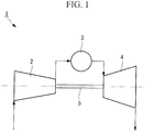
Fig. 1} Fig. 1 is a schematic diagram for explaining the configuration of gas turbines according to an embodiment of the present invention and according to other examples. - {
Fig. 2} Fig. 2 is a schematic diagram for explaining the configuration of a rotor disc and stator blades in a compressor of a gas turbine according to the first example serving to explain features of the present invention. - {
Fig. 3} Fig. 3 is a cross-sectional view for explaining the configuration near a seal holder in the stator blades inFig. 2 . - {
Fig. 4} Fig. 4 is a schematic diagram for explaining another arrangement example of springs inFig. 3 . - {
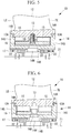
Fig. 5} Fig. 5 is a schematic diagram for explaining attaching and detaching of the seal holder in the stator blades inFig. 3 . - {
Fig. 6} Fig. 6 is a schematic diagram for explaining the state after the seal holder is attached to the stator blades inFig. 3 . - {
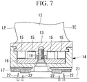
Fig. 7} Fig. 7 is a schematic diagram for explaining yet another arrangement example of the springs inFig. 3 . - {
Fig. 8} Fig. 8 is a schematic diagram for explaining the configuration of a rotor disc and stator blades in a compressor of a gas turbine according to an embodiment of the present invention. - {
Fig. 9} Fig. 9 is a cross-sectional view for explaining the configuration near a seal holder in the stator blades inFig. 8 . - {
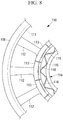
Fig. 10} Fig. 10 is a schematic diagram for explaining an arrangement of springs inFig. 9 according to an embodiment of the invention. - {
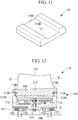
Fig. 11} Fig. 11 is a schematic diagram for explaining the configuration of damping plates inFig. 9 . - {
Fig. 12} Fig. 12 is a schematic diagram for explaining attaching and detaching of the seal holder to and from the stator blades inFig. 9 . - {
Fig. 13} Fig. 13 is a schematic diagram for explaining the state after the seal holder is attached to the stator blades inFig. 9 . - {
Fig. 14} Fig. 14 is a schematic diagram for explaining another embodiment of the springs inFig. 9 - {
Fig. 15} Fig. 15 is a schematic diagram for explaining another configuration of the seal holder inFig. 9 . - {
Fig. 16} Fig. 16 is a schematic diagram for explaining the configuration of a rotor disc and stator blades in a compressor of a gas turbine according to the second example serving to explain features of the present invention. - {
Fig. 17} Fig. 17 is a cross-sectional view for explaining the configuration near a seal holder in the stator blades inFig. 16 . - {
Fig. 18} Fig. 18 is a schematic diagram for explaining another arrangement example of springs inFig. 17 . - {
Fig. 19} Fig. 19 is a schematic diagram for explaining yet another arrangement example of the springs inFig. 17 . -
Fig. 1 is a schematic diagram for explaining the configuration of gas turbines according to the embodiment of the present invention and of other examples described below. - As shown in
Fig. 1 , agas turbine 1 is provided with acompressor 2, acombustor 3, aturbine unit 4, and arotational shaft 5. - As shown in
Fig. 1 , thecompressor 2 sucks in air to compress it and supplies the compressed air to thecombustor 3. A rotational driving force is transmitted from theturbine unit 4 to thecompressor 2 via therotational shaft 5, and, upon being rotationally driven, thecompressor 2 sucks in air and compresses it. - Note that any known configurations can be employed for the
compressor 2; it is not particularly limited. - As shown in
Fig. 1 , thecombustor 3 mixes externally supplied fuel and the supplied compressed air, generates high-temperature gas by combusting the mixed air, and supplies the generated high-temperature gas to theturbine unit 4. - Note that any known combustors can be employed as the
combustor 3; it is not particularly limited. - As shown in
Fig. 1 , theturbine unit 4 extracts rotational driving force from the supplied high-temperature gas to rotationally drive therotational shaft 5. - Note that any known configurations can be employed for the
turbine unit 4; it is not particularly limited. - A gas turbine according to a first example serving to explain features of the present invention will now be described with reference to
Figs. 1 to 7 . Note that, in this example, stator blades of the present application will be described as applied to stator blades of sixth to ninth stages in thecompressor 2 of thegas turbine 1. -
Fig. 2 is a schematic diagram for explaining the configuration of a rotor disc and stator blades in a compressor of a gas turbine according to this example. - As shown in
Figs. 1 and2 , thecompressor 2 is provided withstator blades 10 that are attached to acasing 6 of thegas turbine 1 and rotor blades that are disposed at a circumferential surface of a circular plate-shaped rotor disc (not shown) which is rotationally driven by therotational shaft 5. - The
stator blades 10 and the rotor blades are disposed in rows in the circumferential direction of therotational shaft 5 at regular intervals and are disposed in alternating rows in the axial direction of therotational shaft 5. - Next, the
stator blades 10, which are the feature of this example, will be described. -
Fig. 3 is a cross-sectional view for explaining the configuration near a seal holder in the stator blade inFig. 2 . - As shown in
Figs. 2 and3 , thestator blades 10 are provided with anouter shroud portion 11,airfoil portions 12,inner shroud portions 13, a seal holder (holder casing) 14, springs (elastic portions) 15, a spacer (pressing portion) 16, and ahoneycomb seal 17. - As shown in
Fig. 2 , theouter shroud portion 11 is a member that forms part of wall surfaces of a flow channel in which fluid flows in thecompressor 2. Furthermore, theouter shroud portion 11 is a curved plate-like member disposed at end portions of theairfoil portions 12 on the radially outer side thereof, and a singleouter shroud portion 11 is disposed for a plurality of theairfoil portions 12. In other words, theouter shroud portion 11 is formed of a cylindrical member that has been divided into a plurality of portions, and the plurality of theairfoil portions 12 are connected to an inner circumferential surface thereof. - With regard to the shape of the
outer shroud portion 11 and the connection method with theairfoil portions 12, any known shapes and methods can be employed; they are not particularly limited. - As shown in
Fig. 2 , theairfoil portions 12 are members whose cross-sections extending in the radial direction of therotational shaft 5 are formed in airfoil shapes and that, together with the rotor blades rotationally driven by therotational shaft 5, compress a fluid, such as air, and send it toward thecombustor 3. - The
airfoil portions 12 are provided with leading edges LE, which are upstream-end portions relative to a flow of surrounding fluid, trailing edges TE, which are downstream-end portions, negative pressure surfaces, which are surfaces curved in convex shapes, and positive pressure surfaces, which are curved in concave shapes. - As shown in
Figs. 2 and3 , theinner shroud portions 13, as well as theouter shroud portion 11, form part of the flow channel in which the fluid flows inside thecompressor 2. Furthermore, theinner shroud portions 13 are curved plate-like members disposed at end portions of theairfoil portions 12 on the radially inner side thereof, and a singleinner shroud portion 13 is disposed for asingle airfoil portion 12. In other words, theinner shroud portions 13 are formed of a cylindrical member that has been divided into a plurality of portions, and theairfoil portions 12 are connected to outer circumferential surfaces thereof. - Fitting
grooves 13A that fit with theseal holder 14, extending in the circumferential direction (direction perpendicular to the plane of the drawing inFig. 3 ), are provided at end portions on the leading edge LE side and trailing edge TE side of theinner shroud portions 13. - As shown in
Fig. 3 , theseal holder 14 is a member that is attached to theinner shroud portions 13 on the inner circumferential side thereof (bottom side inFig. 3 ), that, together with theinner shroud portions 13, forms a space for accommodating thesprings 15 and thespacer 16 inside thereof, and that supports thehoneycomb seal 17. - As with the
outer shroud portion 11, asingle seal holder 14 is disposed for the plurality of theairfoil portions 12 and theinner shroud portions 13. - The
seal holder 14 is provided with a pair ofside wall portions 14S that extend in radial directions at the leading edge LE side and the trailing edge TE side and abottom plate portion 14B which connects end portions of the pair ofside wall portions 14S at the radially inner side thereof. - In other words, a groove portion is formed in the
seal holder 14, opening outward in the circumferential direction (top side inFig. 3 ). - The radially outer-side end portions of the
side wall portions 14S are provided withprotrusions 14A which protrude inward in theseal holder 14, extending in the circumferential direction thereof, and fit with thefitting grooves 13A of theinner shroud portions 13. - The
bottom plate portion 14B is provided with through-holes 14H into which compressing bolts (compressing portions) 18 that press thespacer 16 together with thesprings 15 are inserted. The through-holes 14H are provided in thebottom plate portion 14B at an equidistant position from each of the pair ofside wall portions 14S, and a plurality thereof are provided in the circumferential direction (direction perpendicular to the plane of the drawing inFig. 3 ) at predetermined intervals. - As shown in
Figs. 2 and3 , thesprings 15 are elastic members that bias theinner shroud portions 13 in directions that separate them from thespacer 16 and theseal holder 14. Furthermore, by sliding on theinner shroud portions 13, thesprings 15 damp the vibrations in thestator blades 10, i.e., theairfoil portions 12 and theinner shroud portions 13. - In this way, by having the
springs 15 bias theinner shroud portions 13 in the directions that separate them from theseal holder 14, thefitting grooves 13A and theprotrusions 14A are pressed together, coming into close contact with each other, thereby making it possible to ensure the sealing level between theinner shroud portions 13 and theseal holder 14. - The
springs 15 are substantially rectangularly formed plate springs that are formed into substantially a wave shape, and the spring force of thesprings 15 is adjusted by adjusting the plate thickness of the plate springs. With regard to the material forming thesprings 15, the material is desirably capable of maintaining the required spring properties while thegas turbine 1 is in operation, that is, even if thesprings 15 are heated to high temperature. - The
springs 15 are disposed in a space formed between theinner shroud portions 13 and theseal holder 14, more specifically, between theinner shroud portions 13 and thespacer 16. Furthermore, a total of twosprings 15, one on the leading edge LE side and another on the trailing edge TE side, are disposed in a parallel arrangement. - In this example, descriptions will be given as applied to an example in which these two
springs 15 are disposed at the same phase, in other words, an example in which peak portions of the twosprings 15 come in contact with theinner shroud portions 13 or thespacer 16 at the same positions. -
Fig. 4 is a schematic diagram for explaining another arrangement example of the springs. - Note that, the two
springs 15 may be disposed at the same phase, as described above, or they may be disposed at different phases, as shown inFig. 4 ; it is not particularly limited. - With the arrangement of the
springs 15 shown inFig. 4 , at locations where the peak portions of thefirst spring 15 are in contact with theinner shroud portions 13, the peak portions of theother spring 15 are in contact with thespacer 16. - By doing so, it is possible to make the
springs 15 contact all of theinner shroud portions 13, even when arrangement intervals of the peak portions in thefirst spring 15 are wider than arrangement intervals of theinner shroud portions 13. That is, theinner shroud portions 13 with which the peak portions of thefirst spring 15 are not in contact are in contact with the peak portions of theother spring 15, thereby making it possible to have all of theinner shroud portions 13 in contact with thesprings 15. - The shapes of the
springs 15 are determined such that the amplitude of the wave shape (peak-to-peak distance in the radial direction) is longer than the distance from the inner circumferential surfaces of theinner shroud portions 13 to the outer circumferential surface of thespacer 16 and so that the peak portions of thesprings 15 are in contact with the inner circumferential surfaces of individualinner shroud portions 13. - More specifically, the amplitude of the wave shape in the
springs 15 is determined on the basis of the frictional force for damping the vibrations of thestator blades 10, that is, the compression level of thesprings 15 required for generating the spring force. The wavelength (peak-to-peak distance in the circumferential direction) in the wave shape of thesprings 15 is determined on the basis of the arrangement intervals of theinner shroud portions 13, that is, the pitch thereof. - As shown in
Fig. 3 , thespacer 16, together with the compressingbolts 18, presses thesprings 15 toward theinner shroud portions 13 and is disposed between thebottom plate portion 14B of theseal holder 14 and thesprings 15. - As with the
seal holder 14, asingle spacer 16 is disposed for the plurality of theairfoil portions 12 and theinner shroud portions 13. In other words, thespacer 16 is formed of a cylindrical member that has been divided into a plurality of portions, and thesprings 15 come in contact with the inner circumferential surface thereof. - The
spacer 16 is provided with through-holes 16H into which the compressingbolts 18 are inserted. - As shown in
Fig. 3 , thehoneycomb seal 17, together withseal fins 22 provided in arotor 21, suppresses leakage of the fluid that flows between thestator blades 10 and therotor 21. - Any known honeycomb seal may be used as the
honeycomb seal 17, it is not particularly limited. - Next, an assembly method of the
stator blades 10 having the above-described configuration will be described. -
Fig. 5 is a schematic diagram for explaining attaching and detaching of the seal holder in the stator blades inFig. 3 . - First, the
springs 15 and thespacer 16 are disposed on the inner circumferential surface side in theinner shroud portions 13, and the compressingbolts 18 are screwed onto theinner shroud portions 13 via the through-holes 16H of thespacer 16. Then, by screwing the compressingbolts 18 further into theinner shroud portions 13, thespacer 16 is brought closer to theinner shroud portions 13 to compress thesprings 15. - At this time, the distance from the inner circumferential surfaces of the
inner shroud portions 13 to the outer circumferential surface of thespacer 16 is made shorter than the distance from the inner circumferential surfaces of theinner shroud portions 13 to the outer circumferential surface of thebottom plate portion 14B of theseal holder 14. - Subsequently, the
seal holder 14 is fitted to theinner shroud portions 13. More specifically, theprotrusions 14A of theseal holder 14 are fitted to thefitting grooves 13A in theinner shroud portions 13. At this time, theseal holder 14 is fitted while sliding it in the circumferential direction relative to theinner shroud portions 13. -
Fig. 6 is a schematic diagram for explaining the state after the seal holder is attached to the stator blades inFig. 3 . - Then, as shown in
Fig. 6 , the compressingbolts 18 are removed from theinner shroud portions 13 via the through-holes 14H of theseal holder 14, and thus, attaching of theseal holder 14 is completed. - The
seal holder 14 is removed by carrying out the above-described steps sequentially in reverse order. - Note that, the compressing
bolts 18 may be completely removed from thestator blades 10 as described above, or they may remain on thestator blades 10 in a state in which a predetermined level of compression is exerted on thesprings 15; it is not particularly limited. - Next, a method of damping vibrations in the
stator blades 10 having the above-described configuration will be described. - When the
gas turbine 1 is operated, vibrations are generated in thestator blades 10 due to the influence of the fluid or the like flowing in thecompressor 2. More specifically, vibrations are generated by which theairfoil portions 12 and theinner shroud portions 13 of thestator blades 10 vibrate in the circumferential direction. - When the
inner shroud portions 13 vibrate as described above, sliding occurs between the peak portions of thesprings 15, which are pressed against theinner shroud portions 13, and the inner circumferential surfaces of theinner shroud portions 13. The pressing force of thesprings 15 and the frictional force in accordance with the friction coefficient between theinner shroud portions 13 and thesprings 15 act between theinner shroud portions 13 and thesprings 15. - The above-described sliding converts vibrational energy of the
airfoil portions 12 and theinner shroud portions 13 into frictional energy, such as thermal energy and so forth, thereby damping the vibrations in thestator blades 10. - With the above-described configuration, when the
airfoil portions 12 and theinner shroud portions 13 vibrate and slide relative to theseal holder 14, thesprings 15, which have been pressing theinner shroud portions 13 in the direction away from theseal holder 14, and theinner shroud portions 13 relatively move; that is, thesprings 15 and theinner shroud portions 13 slide. Accordingly, energy associated with the vibrations in theairfoil portions 12 and theinner shroud portions 13 is converted into thermal energy (frictional energy) due to sliding, thereby making it possible to damp the vibrations in theairfoil portions 12 and theinner shroud portions 13. - Furthermore, because the compression level of the
springs 15 is adjusted by moving thespacer 16 closer to theinner shroud portions 13, the force with which thesprings 15 press theinner shroud portions 13 is adjusted. In other words, because the frictional force between thesprings 15 and theinner shroud portions 13 is adjusted, it is possible to adjust the level of damping of vibrations in theairfoil portions 12 and theinner shroud portions 13. - On the other hand, the
springs 15 can be easily replaced by attaching/detaching thesprings 15, together with theseal holder 14, to/from theinner shroud portions 13 by sliding them. Accordingly, even if thesprings 15 become deteriorated due to wear from long-term use, thesprings 15 can easily be replaced. - In addition, the
springs 15 are disposed inside the space surrounded by theseal holder 14 and theinner shroud portions 13; therefore, even if thesprings 15 break, it is possible to prevent them from leaping out of the space to damage theairfoil portions 12. - Furthermore, by moving the
spacer 16 closer to theinner shroud portions 13, the biasing force of thesprings 15 is received by theinner shroud portions 13 and thespacer 16. In other words, the biasing force of thesprings 15 does not act on theseal holder 14. Accordingly, when moving theseal holder 14 by sliding it relative to theinner shroud portions 13 or when attaching/detaching theseal holder 14, the frictional force that acts at contact surfaces between theinner shroud portions 13 and theseal holder 14 is reduced, thereby making it possible to facilitate the sliding movement or attaching/detaching. - Because the
inner shroud portions 13 are independently disposed for each of the plurality of theairfoil portions 12, theindividual airfoil portions 12 and theinner shroud portions 13 readily move relative to thesprings 15, as compared with the case in which the plurality of theinner shroud portions 13 are integrally formed. In other words, the sliding distance between theinner shroud portions 13 and thesprings 15 is extended. - Accordingly, a greater amount of energy associated with the vibrations in the
airfoil portions 12 and theinner shroud portions 13 is converted into thermal energy (frictional energy) due to sliding, and therefore, the vibrations in theairfoil portions 12 and theinner shroud portions 13 are more readily damped. - On the other hand, because a
single seal holder 14 is provided for the plurality of theairfoil portions 12 and theinner shroud portions 13, the sealing level between the upstream side and the downstream side of thestator blades 10 can be increased as compared with the case in which theseal holders 14 are disposed for each of the plurality of theairfoil portions 12 and theinner shroud portions 13. - By employing plate-like springs formed into a wave-like shape as the
springs 15, a larger pressing force can be exerted on theinner shroud portions 13 as compared with the case in which other types of springs are employed. - On the other hand, by making each of the peak portions of the
springs 15 individually contact theinner shroud portions 13, the plurality of theinner shroud portions 13 can be moved, by sliding them, with respect to asingle spring 15. - The
spacer 16 can be moved closer to theinner shroud portions 13 using the compressingbolts 18. Accordingly, the compression level of thesprings 15 is adjusted, thereby adjusting the force with which thesprings 15 press theinner shroud portions 13. In other words, because the frictional force between thesprings 15 and theinner shroud portions 13 is adjusted, it is possible to adjust the level of damping of vibrations in theairfoil portions 12 and theinner shroud portions 13. - On the other hand, by moving the
spacer 16 closer to theinner shroud portions 13, the biasing force of thesprings 15 is received by theinner shroud portions 13 and thespacer 16. Accordingly, when moving theseal holder 14 by sliding it relative to theinner shroud portions 13 or when attaching/detaching theseal holder 14, the frictional force that acts at contact surfaces between theinner shroud portions 13 and theseal holder 14 is reduced, thereby making it possible to facilitate the sliding movement or attaching/detaching. -
Fig. 7 is a schematic diagram for explaining yet another arrangement example of the springs inFig. 3 . - Note that, two
springs 15 may be disposed between theinner shroud portions 13 and thespacer 16, as in the example described above, or, as shown inFig. 7 , foursprings 15 may be disposed between theinner shroud portions 13 and thespacer 16; the number of thesprings 15 is not particularly limited. - Furthermore, the
spacer 16 may be pressed toward theinner shroud portions 13 by screwing the compressingbolts 18 onto theinner shroud portions 13 as in the above-described example, or thespacer 16 may be pressed toward theinner shroud portions 13 by screwing thepressing springs 15 onto theseal holder 14 to thereby press the tip of thepressing springs 15 against thespacer 16; it is not particularly limited. - As in the example described above, the
gas turbine 1 may be operated in a state in which thespacer 16 remains between theseal holder 14 and theinner shroud portions 13, or thegas turbine 1 may be operated with thespacer 16 removed from between theseal holder 14 and theinner shroud portions 13; it is not particularly limited. - As in the example described above, the spring force of the
springs 15 may be adjusted by adjusting the compression level of thesprings 15 using the compressingbolts 18 or, even in a state in which the compressingbolts 18 are removed, the spring force of thesprings 15 may be adjusted by adjusting only the plate thickness of thespacer 16; it is not particularly limited. - A gas turbine according to the present invention will be described with reference to
Figs. 8 to 15 . Note that stator blades of the invention of the present application will be described as applied to stator blades of first to fourth stages in thecompressor 2 of thegas turbine 1. -
Fig. 8 is a schematic diagram for explaining the configuration of a rotor disc and stator blades in a compressor of a gas turbine. - As shown in
Figs. 1 and8 , thecompressor 2 is provided withstator blades 110 that are attached to acasing 6 of thegas turbine 1 and rotor blades that are disposed at a circumferential surface of a circular plate-shaped rotor disc (not shown) which is rotationally driven by therotational shaft 5. - The
stator blades 110 and the rotor blades are disposed in rows in the circumferential direction of therotational shaft 5 at regular intervals and are disposed in alternating rows in the axial direction of therotational shaft 5. - Next, the
stator blades 110 will be described. -
Fig. 9 is a cross-sectional view for explaining the configuration near a seal holder in the stator blade inFig. 8 . - As shown in
Figs. 8 and9 , thestator blades 110 are provided with anouter shroud portion 111,airfoil portions 112,inner shroud portions 113, a seal holder (holder casing) 114, springs (elastic portions) 115, damping plates (friction portions) 116, and ahoneycomb seal 117. - As shown in
Fig. 8 , theouter shroud portion 111 is a member that forms part of wall surfaces of a flow channel in which fluid flows in thecompressor 2. Furthermore, theouter shroud portion 111 is a curved plate-like member disposed at end portions of theairfoil portions 112 on the radially outer side thereof, and a singleouter shroud portion 111 is disposed for a plurality of theairfoil portions 112. In other words, theouter shroud portion 111 is formed of a cylindrical member that has been divided into a plurality of portions, and the plurality of theairfoil portions 112 are connected to an inner circumferential surface thereof. - With regard to the shape of the
outer shroud portion 111 and the connection method with theairfoil portions 112, any known shapes and methods can be employed; they are not particularly limited. - As shown in
Fig. 8 , theairfoil portions 112 are members whose cross-sections extending in the radial direction of therotational shaft 5 are formed in airfoil shapes and that, together with the rotor blades rotationally driven by therotational shaft 5, compress a fluid, such as air, and send it toward thecombustor 3. - The
airfoil portions 112 are provided with leading edges LE, which are upstream-end portions relative to a flow of surrounding fluid, trailing edges TE, which are downstream-end portions, negative pressure surfaces, which are surfaces curved in convex shapes, and positive pressure surfaces, which are curved in concave shapes. - As shown in
Figs. 8 and9 , theinner shroud portions 113, as well as theouter shroud portion 111, form part of the flow channel in which the fluid flows inside thecompressor 2. Furthermore, theinner shroud portions 113 are curved plate-like members disposed at end portions of theairfoil portions 112 on radially inner side thereof, and a singleinner shroud portion 113 is disposed for asingle airfoil portion 112. In other words, theinner shroud portions 113 are formed of a cylindrical member that has been divided into a plurality of portions, and theairfoil portions 112 are connected to outer circumferential surfaces thereof. - Fitting
grooves 113A that fit with theseal holder 114, extending in the circumferential direction (direction perpendicular to the plane of the drawing inFig. 9 ), are provided at end portions on the leading edge LE side and trailing edge TE side of theinner shroud portions 113. - As shown in
Fig. 9 , theseal holder 114 is a member that is attached to theinner shroud portions 113 on the inner circumferential side thereof (bottom side inFig. 9 ), that, together with theinner shroud portions 113, forms a space for accommodating thesprings 115 and the dampingplates 116 inside thereof, and that supports thehoneycomb seal 117. - As with the
outer shroud portion 111, asingle seal holder 114 is disposed for the plurality of theairfoil portions 112 and theinner shroud portions 113. - The
seal holder 114 is provided with a pair ofside wall portions 114S that extend in radial directions at the leading edge LE side and the trailing edge TE side and abottom plate portion 114B which connects end portions of the pair ofside wall portions 114S at the radially inner side thereof. - In other words, a groove portion is formed in the
seal holder 114, opening outward in the circumferential direction (top side inFig. 9 ). - The radially outer-side end portions of the
side wall portions 114S are provided withprotrusions 114A which protrude inward in theseal holder 114, extending in the circumferential direction thereof, and fit with thefitting grooves 113A of theinner shroud portions 113. - The
bottom plate portion 114B is provided with through-holes 114H into which compressing bolts (compressing portions) 118 that press the dampingplates 116 together with thesprings 115 are inserted. The through-holes 114H are provided in thebottom plate portion 114B at an equidistant position from each of the pair ofside wall portions 114S and a plurality thereof are provided in the circumferential direction (direction perpendicular to the plane of the drawing inFig. 9 ) at predetermined intervals. - As shown in
Figs. 8 and9 , thesprings 115 are elastic members that bias theinner shroud portions 113 and the dampingplates 116 in directions that separate them from theseal holder 114. Furthermore, thesprings 115, together with the dampingplates 116, damp the vibrations in thestator blades 110, i.e., theairfoil portions 112, and theinner shroud portions 113. - In this way, by having the
springs 115 bias theinner shroud portions 113 in the directions that separate them from theseal holder 114, thefitting grooves 113A and theprotrusions 114A are pressed together, coming into close contact with each other, thereby making it possible to ensure the sealing level between theinner shroud portions 113 and theseal holder 114. - The
springs 115 are substantially rectangularly formed plate springs that are formed into substantially a wave shape, and the spring force of thesprings 115 is adjusted by adjusting the plate thickness of the plate springs. With regard to the material forming thesprings 115, the material is desirably capable of maintaining the required spring properties while thegas turbine 1 is in operation, that is, even if thesprings 115 are heated to high temperature. - The
springs 115 are disposed in the space formed between theinner shroud portions 113 and theseal holder 114, more specifically, between theseal holder 114 and the dampingplates 116. Furthermore, a total of twosprings 115, one on the leading edge LE side and another on the trailing edge TE side, are disposed in a parallel arrangement. - In a non-claimed example, these two
springs 115 are disposed at the same phase, in other words, an example in which peak portions of the twosprings 115 come in contact with the dampingplates 116 or theseal holder 114 at the same positions. -
Fig. 10 is a schematic diagram for further illustrating the positioning of the springs inFig. 9 . Note that, the twosprings 115 are disposed at different phases, as shown inFig. 10 . - With the arrangement of the
springs 115 shown inFig. 10 , at locations where the peak portions of thefirst spring 115 are in contact with the dampingplates 116, the peak portions of theother spring 115 are in contact with theseal holder 114. - By doing so, it is possible to make the
springs 115 contact all of the dampingplates 116, even when arrangement intervals of the peak portions in thefirst spring 115 are wider than arrangement intervals of theinner shroud portions 113 and the dampingplates 116. That is, the dampingplates 116 with which the peak portions of thefirst spring 115 are not in contact are in contact with the peak portions of theother spring 115, thereby making it possible to have all of the dampingplates 116 in contact with thesprings 115. - The shapes of the
springs 115 are determined such that the amplitude of the wave shape (peak-to-peak distance in the radial direction) is longer than the distance from the outer circumferential surfaces of the dampingplates 116 to the inner circumferential surface of theseal holder 114 and so that the peak portions of thesprings 115 are in contact with the inner circumferential surfaces of individual dampingplates 116. - More specifically, the amplitude of the wave shape in the
springs 115 is determined on the basis of the frictional force for damping the vibrations of thestator blades 110, that is, the compression level of thesprings 115 required for generating the spring force. The wavelength (peak-to-peak distance in the circumferential direction) in the wave shape of thesprings 115 is determined on the basis of the arrangement intervals of theinner shroud portions 113 and dampingplates 116, that is, the pitch thereof. - As shown in
Fig. 9 , the dampingplates 116 are pressed against the inner circumferential surfaces of theinner shroud portions 113 by thesprings 115 and are disposed between theinner shroud portions 113 and thesprings 115. - As with the
inner shroud portions 113, one dampingplate 116 is disposed for each of the plurality of theairfoil portions 112 and theinner shroud portions 113. -
Fig. 11 is a schematic diagram for explaining the configuration of the damping plates inFig. 9 . - The damping
plates 116 are provided withbolt holes 116H into which the compressingbolts 118 are screwed andrelief grooves 116G formed on surfaces facing theinner shroud portions 113. - The bolt holes 116H are female screw holes formed substantially at the center of the damping
plates 116 and the compressingbolts 118 are screwed thereinto. - First end portions of the compressing
bolts 118 are screwed into the bolt holes 116H of the dampingplates 116. Second end portions of the compressingbolts 118 are inserted into the through-holes 114H of theseal holder 114. The nuts (compressing portions) 119, which compress thesprings 115 together with the compressingbolts 118, are threaded onto the second end portions of the compressingbolts 118. - As shown in
Figs. 9 and11 , therelief grooves 116G are grooves formed on the surfaces (top-side surfaces inFigs. 9 and11 ) of the dampingplates 116 facing theinner shroud portions 113. In addition, therelief grooves 116G are grooves extending in the direction parallel to the direction in which therotational shaft 5 extends, in other words, grooves extending in a direction that intersect with, more preferably a direction perpendicular to, the direction in which the dampingplates 116 and theinner shroud portions 113 slide. - By providing the
relief grooves 116G in this way, the surfaces of the dampingplates 116 that come into contact with theinner shroud portions 113 are divided into two with therelief grooves 116G therebetween, and each surface comes into contact with theinner shroud portions 113. Accordingly, even if theinner shroud portions 113 and the dampingplates 116 slide, theinner shroud portions 113 and the dampingplates 116 come into stable contact at the above-described two surfaces, thereby preventing the occurrence of problems such as partial contact or the like. - As shown in
Fig. 9 , thehoneycomb seal 117, together withseal fins 122 provided in arotor 21, suppresses leakage of a fluid that flows between thestator blades 110 and therotor 21. - Any known honeycomb seal may be used as the
honeycomb seal 117; it is not particularly limited. - Next, an assembly method not forming part of the present invention of the
stator blades 110 having the above-described configuration will be described. -
Fig. 12 is a schematic diagram for explaining attaching and detaching of the seal holder in the stator blades inFig. 9 . - First, the
springs 115 and the dampingplates 116 are disposed inside theseal holder 114, and the second end portions of the compressingbolts 118 are inserted into the through-holes 114H of theseal holder 114. Then, by threading thenuts 119 on the second end portions of the compressingbolts 118, the dampingplates 116 are brought closer to thebottom plate portion 114B of theseal holder 114, thereby compressing thesprings 115. - At this time, the distance from the outer circumferential surface of the
bottom plate portion 114B to the outer circumferential surfaces of the dampingplates 116 is made shorter than the distance from the outer circumferential surface of thebottom plate portion 114B to the inner circumferential surfaces of theinner shroud portions 113. - Subsequently, the
seal holder 114 is fitted to theinner shroud portions 113. More specifically, theprotrusions 114A of theseal holder 114 are fitted to thefitting grooves 113A in theinner shroud portions 113. At this time, theseal holder 114 is fitted while sliding it in the circumferential direction relative to theinner shroud portions 113. -
Fig. 13 is a schematic diagram for explaining the state after the seal holder is attached to the stator blade inFig. 9 . - Then, as shown in
Fig. 13 , thenuts 119 are removed from the compressingbolts 118, and the dampingplates 116 are brought into contact with theinner shroud portions 113, thereby completing the attaching of theseal holder 114. - The
seal holder 114 is removed by carrying out the above-described steps sequentially in reverse order. - Note that, the compressing
bolts 118 may be left attached to the dampingplates 116, as described above, or they may be removed from the dampingplates 116; it is not particularly limited. - Next, a method of damping vibrations in the
stator blades 110 having the above-described configuration will be described. - When the
gas turbine 1 is operated, vibrations are generated in thestator blades 110 due to the influence of the fluid or the like flowing in thecompressor 2. More specifically, vibrations are generated by which theairfoil portions 112 and theinner shroud portions 113 of thestator blades 110 vibrate in the circumferential direction. - When the
inner shroud portions 113 vibrate as described above, sliding occurs between the dampingplates 116, which are pressed against theinner shroud portions 113, and the inner circumferential surfaces of theinner shroud portions 113. The pressing force of thesprings 115 and the frictional force in accordance with the friction coefficient between theinner shroud portions 113 and the dampingplates 116 act between theinner shroud portions 113 and the dampingplates 116. - The above-described sliding converts vibrational energy of the
airfoil portions 112 and theinner shroud portions 113 into frictional energy, such as thermal energy and so forth, thereby damping the vibrations in thestator blades 110. - With the above-described configuration, when the
airfoil portions 112 and theinner shroud portions 113 vibrate and slide relative to theseal holder 114, the dampingplates 116, which have been pressed against theinner shroud portions 113, and theinner shroud portions 113 relatively move; that is, the dampingplates 116 and theinner shroud portions 113 slide. Accordingly, energy associated with the vibrations in theairfoil portions 112 and theinner shroud portions 113 is converted into thermal energy (frictional energy) due to the sliding, thereby making it possible to damp the vibrations in theairfoil portions 112 and theinner shroud portions 113. - On the other hand, by moving the damping
plates 116 closer to theseal holder 114, the biasing force of thesprings 115 is received by the dampingplates 116 and theseal holder 114. In other words, the biasing force of thesprings 115 does not directly act on theinner shroud portions 113. Accordingly, when moving theseal holder 114 by sliding it relative to theinner shroud portions 113 or when attaching/detaching theseal holder 114, the frictional force that acts at contact surfaces between theinner shroud portions 113 and theseal holder 114 is reduced, thereby making it possible to facilitate the sliding movement or attaching/detaching. - Furthermore, the
springs 115 can be easily replaced by attaching/detaching thesprings 115, together with theseal holder 114, to/from theinner shroud portions 113 by sliding them. Accordingly, even if thesprings 115 become deteriorated due to wear from long-term use, thesprings 115 can easily be replaced. - In addition, the
springs 115 are disposed inside the space surrounded by theseal holder 114 and theinner shroud portions 113; therefore, even if thesprings 115 break, it is possible to prevent them from leaping out of the space to damage theairfoil portions 112. - Because the
inner shroud portions 113 are independently disposed for each of the plurality of theairfoil portions 112, theindividual airfoil portions 112 and theinner shroud portions 113 readily move relative to the dampingplates 116, as compared with the case in which the plurality of theinner shroud portions 113 are integrally formed. In other words, the sliding distance between theinner shroud portions 113 and the dampingplates 116 is extended. - Accordingly, a greater amount of energy associated with the vibrations in the
airfoil portions 112 and theinner shroud portions 113 is converted into thermal energy (frictional energy) due to sliding, and therefore, the vibrations in theairfoil portions 112 and theinner shroud portions 113 are more readily damped. - On the other hand, because a
single seal holder 114 is provided for the plurality of theairfoil portions 112 and theinner shroud portions 113, the sealing level between the upstream side and the downstream side of thestator blades 110 can be increased as compared with the case in which theseal holders 114 are disposed for each of the plurality of theairfoil portions 112 and theinner shroud portions 113. - By employing springs formed into a wave-like shape as the
springs 115, a larger pressing force can be exerted on theinner shroud portions 113 as compared with the case in which other types of springs are employed. - On the other hand, by making each of the peak portions of the
springs 115 individually contact the dampingplates 116, the plurality of the dampingplates 116 are pressed against theinner shroud portions 113 by a single spring. - Because the compressing
bolts 118 protrude from the dampingplates 116 penetrating theseal holder 114, the compressingbolts 118 and the dampingplates 116 are movable in directions toward and away from theseal holder 114, while being restricted in movement in the direction that intersects with the direction of movement toward/away from theseal holder 114; that is, movement in the circumferential direction of therotational shaft 5 is restricted. Accordingly, it is ensured that sliding occurs between theinner shroud portions 113 and the dampingplates 116. -
Fig. 14 is a schematic diagram for explaining another embodiment showing a variation of the springs inFig. 9 . - Note that, two
springs 115 may be disposed between the dampingplates 116 and theseal holder 114, as in the embodiment described above, or, as shown inFig. 14 , foursprings 115 may be disposed between the dampingplates 116 and theseal holder 114; the number of thesprings 115 is not particularly limited. -
Fig. 15 is a schematic diagram for explaining another configuration of the seal holder inFig. 9 . - Note that, as in the above-described embodiment, the
honeycomb seal 117 may be disposed in theseal holder 114, and theseal fins 122 may be disposed at therotor 21 or, as shown inFig. 15 ,seal fins 122 may be disposed in theseal holder 114, configuring them as a labyrinth seal in which steps are provided at positions that face theseal fins 122 of therotor 21; it is not particularly limited. - As in the embodiment described above, the spring force of the
springs 115 may be adjusted by adjusting the compression level of thesprings 115 using compressingbolts 118 and thenuts 119 or, even in a state in which thenuts 119 are removed, the spring force of thesprings 115 may be adjusted by adjusting only the plate thickness of the dampingplates 116; it is not particularly limited. - A gas turbine according to a second example serving to explain features of this invention will now be described with reference to
Fig. 1 andFigs. 16 to 19 . Note that, in this example, stator blades of the present application will be described as applied to stator blades of first to third, fifth to seventeenth, or tenth to fourteenth stages in thecompressor 2 of thegas turbine 1. -
Fig. 16 is a schematic diagram for explaining the configuration of a rotor disc and stator blades in a compressor of a gas turbine according to this example. - As shown in
Figs. 1 and16 , thecompressor 2 is provided with stator blades (turbine blades) 210 that are attached to acasing 6 of thegas turbine 1 and rotor blades that are disposed at a circumferential surface of a circular plate-like rotor disc (not shown) which is rotationally driven by therotational shaft 5. - The
stator blades 210 and the rotor blades are disposed in rows in the circumferential direction of therotational shaft 5 at regular intervals and are disposed in alternating rows in the axial direction of therotational shaft 5. - Next, the
stator blades 210, which are the feature of this example, will be described. -
Fig. 17 is a cross-sectional view for explaining the configuration near a seal holder in the stator blades inFig. 16 . - In this example, the
stator blades 210 will be described as applied to stator blades with fixed pitch, in other words, stator blades with fixed angles of attack with respect to the flow of the fluid flowing inside thecompressor 2. - As shown in
Figs. 16 and17 , thestator blades 210 are provided with anouter shroud portion 211,airfoil portions 212,inner shroud portions 213, a seal holder (holder casing) 214, springs (elastic portions) 215, and ahoneycomb seal 217. - As shown in
Fig. 16 , theouter shroud portion 211 is a member that forms part of wall surfaces of a flow channel in which fluid flows in thecompressor 2. Furthermore, theouter shroud portion 211 is a curved plate-like member disposed at end portions of theairfoil portions 212 on the radially outer side thereof, and a singleouter shroud portion 211 is disposed for a plurality of theairfoil portions 212. In other words, theouter shroud portion 211 is formed of a cylindrical member that has been divided into a plurality of portions, and the plurality of theairfoil portions 212 are connected to an inner circumferential surface thereof. - With regard to the shape of the
outer shroud portion 211 and the connection method with theairfoil portions 212, any known shapes and methods can be employed; they are not particularly limited. - As shown in
Fig. 16 , theairfoil portions 212 are members whose cross-sections extending in the radial direction of therotational shaft 5 are formed in airfoil shapes and that, together with the rotor blades rotationally driven by therotational shaft 5, compress a fluid such as air and send it toward thecombustor 3. - The
airfoil portions 212 are provided with leading edges LE, which are upstream-end portions relative to a flow of surrounding fluid, trailing edges TE, which are downstream-end portions, negative pressure surfaces, which are surfaces curved in convex shapes, and positive pressure surfaces, which are curved in concave shapes. - As shown in
Figs. 16 and17 , theinner shroud portions 213, as well as theouter shroud portion 211, form part of the flow channel in which the fluid flows inside thecompressor 2. Furthermore, theinner shroud portions 213 are curved plate-like members disposed at end portions of theairfoil portions 212 on radially inner side thereof, and a singleinner shroud portion 213 is disposed for asingle airfoil portion 212. In other words, theinner shroud portions 213 are formed of a cylindrical member that has been divided into a plurality of portions, and theairfoil portions 212 are connected to outer circumferential surfaces thereof. - Fitting
grooves 213A that fit with theseal holder 214, extending in the circumferential direction (direction perpendicular to the plane of the drawing inFig. 17 ), are provided at end portions on the leading edge LE side and trailing edge TE side of theinner shroud portions 213. - As shown in
Fig. 17 , theseal holder 214 is a member that is attached to theinner shroud portions 213 on the inner circumferential side thereof (bottom side inFig. 17 ), that, together with theinner shroud portions 213, forms a space for accommodating thesprings 215 inside thereof, and that supports thehoneycomb seal 217. - As with the
outer shroud portion 211, asingle seal holder 214 is disposed for the plurality of theairfoil portions 212 and theinner shroud portions 213. - The
seal holder 214 is provided with a pair of side wall portions 214S that extend in radial directions at the leading edge LE side and the trailing edge TE side and abottom plate portion 214B which connects end portions of the pair of side wall portions 214S at radially inner side thereof. - In other words, a groove portion is formed in the
seal holder 214, opening outward in the circumferential direction (top side inFig. 17 ). - The radially outer-side end portions of the side wall portions 214S are provided with
protrusions 214A which protrude inward in theseal holder 214, extending in the circumferential direction thereof, and fit with thefitting grooves 213A of theinner shroud portions 213. - As shown in
Figs. 16 and17 , thesprings 215 are elastic members that bias theinner shroud portions 213 in directions that separate them from theseal holder 214. Furthermore, by sliding on theinner shroud portions 213, thesprings 215 damp the vibrations in thestator blades 210, i.e., theairfoil portions 212, and the inner shouldportions 213. - In this way, by having the
springs 215 bias theinner shroud portions 213 in the directions that separate them from theseal holder 214, thefitting grooves 213A and theprotrusions 214A are pressed together, coming into close contact with each other, thereby making it possible to ensure the sealing level between theinner shroud portions 213 and theseal holder 214. - The
springs 215 are substantially rectangularly formed plate springs that are formed into substantially a wave shape, and the spring force of thesprings 215 is adjusted by adjusting the plate thickness of the plate springs. With regard to the material forming thesprings 215, the material is desirably capable of maintaining the required spring properties while thegas turbine 1 is in operation, that is, even if thesprings 215 are heated to high temperature. - The
springs 215 are disposed in a space formed between theinner shroud portions 213 and theseal holder 214, more specifically, between theinner shroud portions 213 and theseal holder 214. Furthermore, a total of twosprings 215, one on the leading edge LE side and another on the trailing edge TE side, are disposed in a parallel arrangement. - In this example, descriptions will be given as applied to an example in which these two
springs 215 are disposed at the same phase, in other words, an example in which peak portions of the twosprings 215 come in contact with theinner shroud portions 213 or theseal holder 214 at the same positions. -
Fig. 18 is a schematic diagram for explaining another arrangement example of springs inFig. 17 . - Note that, the two
springs 215 may be disposed at the same phase, as described above, or they may be disposed at different phases, as shown inFig. 18 ; it is not particularly limited. - With the arrangement of the
springs 215 shown inFig. 18 , at locations where the peak portions of thefirst spring 215 are in contact with theinner shroud portions 213, the peak portions of theother spring 215 are in contact with theseal holder 214. - By doing so, it is possible to make the
springs 215 contact all of theinner shroud portions 213, even when arrangement intervals of the peak portions in thefirst spring 215 are wider than arrangement intervals of theinner shroud portions 213. That is, theinner shroud portions 213 with which the peak portions of thefirst spring 215 are not in contact are in contact with the peak portions of theother spring 215, thereby making it possible to have all of theinner shroud portions 213 in contact with thesprings 215. - The shapes of the
springs 215 are determined such that the amplitude of the wave shape (peak-to-peak distance in the radial direction) is longer than the distance from the inner circumferential surfaces of theinner shroud portions 213 to the outer circumferential surface of theseal holder 214 and so that the peak portions of thesprings 215 are in contact with the inner circumferential surfaces of individualinner shroud portions 213. - More specifically, the amplitude of the wave shape in the
springs 215 is determined on the basis of the frictional force for damping the vibrations of thestator blades 210, that is, the compression level of thesprings 215 required for generating the spring force. The wavelength (peak-to-peak distance in the circumferential direction) in the wave shape of thesprings 215 is determined on the basis of the arrangement intervals of theinner shroud portions 213, that is, the pitch, thereof. - As shown in
Fig. 17 , thehoneycomb seal 217, together withseal fins 222 provided in therotor 21, suppresses leakage of a fluid that flows between thestator blades 210 and therotor 21. - Any known honeycomb seal may be used as the
honeycomb seal 217; it is not particularly limited. - Next, a method of damping vibrations in the
stator blades 210 having the above-described configuration will be described. - When the
gas turbine 1 is operated, vibrations are generated in thestator blades 210 due to the influence of the fluid or the like flowing in thecompressor 2. More specifically, vibrations are energized by which theairfoil portions 212 and theinner shroud portions 213 of thestator blades 210 vibrate in the circumferential direction. - When the
inner shroud portions 213 vibrate as described above, sliding occurs between the peak portions of thesprings 215, which are pressed against theinner shroud portions 213, and the inner circumferential surfaces of theinner shroud portions 213. The pressing force of thesprings 215 and the frictional force in accordance with the friction coefficient between theinner shroud portions 213 and thesprings 215 act between theinner shroud portions 213 and thesprings 215. - The above-described sliding converts vibrational energy of the
airfoil portions 212 and theinner shroud portions 213 into thermal energy, such as frictional energy and so forth, thereby damping the vibrations in thestator blades 210. - With the above-described configuration, when the
airfoil portions 212 and theinner shroud portions 213 vibrate and slide relative to theseal holder 214, thesprings 215 and theinner shroud portions 213 relatively move; that is, thesprings 215 and theinner shroud portions 213 slide. Accordingly, energy associated with the vibrations in theairfoil portions 212 and theinner shroud portions 213 is converted into thermal energy (frictional energy) due to the sliding, thereby making it possible to damp the vibrations in theairfoil portions 212 and theinner shroud portions 213. - On the other hand, the
springs 215 can be easily replaced by attaching/detaching thesprings 215, together with theseal holder 214, to/from theinner shroud portions 213 by sliding them. Accordingly, even if thesprings 215 become deteriorated due to wear from long-term use, thesprings 215 can easily be replaced. - In addition, the
springs 215 are disposed inside the space surrounded by theseal holder 214 and theinner shroud portions 213; therefore, even if thesprings 215 break, it is possible to prevent them from leaping out of the space to damage theairfoil portions 212. - Because the
inner shroud portions 213 are independently disposed for each of the plurality of theairfoil portions 212, theindividual airfoil portions 212 and theinner shroud portions 213 readily move relative to thesprings 215, as compared with the case in which the plurality of theinner shroud portions 213 are integrally formed. In other words, the sliding distance between theinner shroud portions 213 and thesprings 215 is extended. - Accordingly, a greater amount of energy associated with the vibrations in the
airfoil portions 212 and theinner shroud portions 213 is converted into thermal energy (frictional energy) due to sliding, and therefore, greater damping of the vibrations in theairfoil portions 212 and theinner shroud portions 213 is possible. -
Fig. 19 is a schematic diagram for explaining yet another arrangement example of the springs inFig. 17 . - Note that, two
springs 215 may be disposed between theinner shroud portions 213 and theseal holder 214, as in the example described above, or, as shown inFig. 19 , foursprings 215 may be disposed between theinner shroud portions 213 and theseal holder 214; the number of thesprings 215 is not particularly limited. -
- 1 gas turbine
- 10, 110, 210 stator blade
- 12, 112, 212 airfoil portion
- 13, 113, 213 inner shroud portion
- 14, 114, 214 seal holder (holder casing)
- 15, 115, 215 spring (elastic portion)
- 16 spacer (pressing portion)
- 18 compressing bolt (compressing portion)
- 116 damping plate (friction portion)
- 116G relief groove
- 118 compressing bolt (compressing portion)
- 119 nut (compressing portion)
Claims (6)
- A gas turbine stator blade structure (110) comprising:a plurality of inner shroud portions (113) each disposed at each end portion of a plurality of airfoil portions (112);a holder casing (114) that can be moved by sliding relative to the plurality of inner shroud portions (113), that can also be attached thereto/detached therefrom, and that forms a space with the plurality of inner shroud portions (113) therebetween;an elastic portion (115) that is disposed in the space, and that biases the plurality of inner shroud portions (113) in a direction that separates them from the holder casing (114); characterized in that the gas turbine stator blade structure further comprisesa plurality of friction portions (116) that are disposed between the elastic portion (115) and the plurality of inner shroud portions (113), that can be moved closer to or away from the plurality of inner shroud portions (113), and that are disposed in a movable manner relative to the plurality of inner shroud portions (113),wherein the elastic portion (115) extends parallel to the direction in which the plurality of inner shroud portions (113) form a row and comprises a plurality of plate-like springs (115) each formed in substantially a wave shape,peak portions of the plurality of springs (115) are in contact with the friction portions (116) or the holder casing (114), andthe plurality of springs (115) are disposed in substantially parallel rows and, relative to peak portions of one of the plurality of springs (115), peak portions of the other spring (115) of the plurality of springs (115) are disposed shifted therefrom.
- The gas turbine stator blade structure (110) according to Claim 1, wherein each of the plurality of inner shroud portions (113) is independently disposed for each of the plurality of airfoil portions (112);
for a plurality of inner shroud portions (113), a single holder casing (114) is configured in an attachable or detachable manner; and
in the space formed by the plurality of inner shroud portions (113) and the single holder casing (114), a single friction portion (116) is disposed for a single inner shroud portion (113). - The gas turbine stator blade structure (110) according to Claim 1 or 2, wherein the friction portion (116) is provided with a compressing portion (118) that extends from the friction portion (116) toward the holder casing (114), protrudes so as to penetrate the holder casing (114), and compresses the elastic portion (115) by moving the friction portion (116) closer to the holder casing (114).
- The gas turbine stator blade structure (110) according to any one of Claims 1 to 3, wherein a relief groove (116G) that extends in a direction that intersects with the direction into which the holder casing (114) slides is in the friction portion (116) at a surface where the friction portion (116) comes in contact with the inner shroud portion (113).
- A gas turbine (1) provided with the gas turbine stator blade structure (110) according to any one of claims 1 to 4.
- A method of damping vibrations of a gas turbine stator blade structure (110), comprising:a sliding-occuring step of, when inner shroud portions (113) each disposed at each end portion of a plurality of airfoil portions (112) vibrate, having sliding occur between a plurality of friction portions (116), which are pressed against the inner shroud portions (113), by a plurality of elastic portions (115) and an inside of the inner shroud portions (113); andan energy-converting step of converting, by the sliding having occurred in the sliding-occuring step, vibrational energy of the vibration into frictional energy that occurs between the inner shroud portions (113) and the friction portions (116),wherein each of the elastic portions (115) extends parallel to the direction in which a plurality of inner shroud portions (113) form a row and comprises a plurality of plate-like springs (115) each formed in substantially a wave shape, andwherein the inner shroud portions (113) with which peak portions of a first spring (115) are not in contact are in contact with peak portions of the other spring (115), whereby all of the inner shroud portions (113) are in contact with the springs (115).
Applications Claiming Priority (6)
| Application Number | Priority Date | Filing Date | Title |
|---|---|---|---|
| JP2008330613A JP5501610B2 (en) | 2008-12-25 | 2008-12-25 | Turbine blade and gas turbine |
| JP2008330612A JP5501609B2 (en) | 2008-12-25 | 2008-12-25 | Turbine blade and gas turbine |
| JP2008330614A JP5501611B2 (en) | 2008-12-25 | 2008-12-25 | Turbine blade and gas turbine |
| PCT/JP2009/066515 WO2010073783A1 (en) | 2008-12-25 | 2009-09-24 | Turbine blade and gas turbine |
| EP09834589.5A EP2372165B1 (en) | 2008-12-25 | 2009-09-24 | Stator blade structure and gas turbine |
| EP15160927.8A EP2905475B1 (en) | 2008-12-25 | 2009-09-24 | Stator blade assembly and gas turbine |
Related Parent Applications (3)
| Application Number | Title | Priority Date | Filing Date |
|---|---|---|---|
| EP15160927.8A Division EP2905475B1 (en) | 2008-12-25 | 2009-09-24 | Stator blade assembly and gas turbine |
| EP15160927.8A Division-Into EP2905475B1 (en) | 2008-12-25 | 2009-09-24 | Stator blade assembly and gas turbine |
| EP09834589.5A Division EP2372165B1 (en) | 2008-12-25 | 2009-09-24 | Stator blade structure and gas turbine |
Publications (2)
| Publication Number | Publication Date |
|---|---|
| EP3054169A1 EP3054169A1 (en) | 2016-08-10 |
| EP3054169B1 true EP3054169B1 (en) | 2019-02-20 |
Family
ID=42287409
Family Applications (4)
| Application Number | Title | Priority Date | Filing Date |
|---|---|---|---|
| EP09834589.5A Active EP2372165B1 (en) | 2008-12-25 | 2009-09-24 | Stator blade structure and gas turbine |
| EP15160927.8A Active EP2905475B1 (en) | 2008-12-25 | 2009-09-24 | Stator blade assembly and gas turbine |
| EP16160027.5A Active EP3054169B1 (en) | 2008-12-25 | 2009-09-24 | Stator blade assembly and gas turbine |
| EP15160928.6A Active EP2905476B1 (en) | 2008-12-25 | 2009-09-24 | Stator blade assembly and gas turbine |
Family Applications Before (2)
| Application Number | Title | Priority Date | Filing Date |
|---|---|---|---|
| EP09834589.5A Active EP2372165B1 (en) | 2008-12-25 | 2009-09-24 | Stator blade structure and gas turbine |
| EP15160927.8A Active EP2905475B1 (en) | 2008-12-25 | 2009-09-24 | Stator blade assembly and gas turbine |
Family Applications After (1)
| Application Number | Title | Priority Date | Filing Date |
|---|---|---|---|
| EP15160928.6A Active EP2905476B1 (en) | 2008-12-25 | 2009-09-24 | Stator blade assembly and gas turbine |
Country Status (5)
| Country | Link |
|---|---|
| US (1) | US8708641B2 (en) |
| EP (4) | EP2372165B1 (en) |
| KR (1) | KR101271363B1 (en) |
| CN (1) | CN102132047B (en) |
| WO (1) | WO2010073783A1 (en) |
Families Citing this family (21)
| Publication number | Priority date | Publication date | Assignee | Title |
|---|---|---|---|---|
| US9353649B2 (en) * | 2013-01-08 | 2016-05-31 | United Technologies Corporation | Wear liner spring seal |
| EP2818642A1 (en) | 2013-06-28 | 2014-12-31 | Siemens Aktiengesellschaft | Seal ring segment for a stator of a turbine |
| US9267387B2 (en) * | 2013-07-15 | 2016-02-23 | General Electric Company | Seal platform |
| EP3123002B1 (en) * | 2014-03-27 | 2019-01-09 | Siemens Aktiengesellschaft | Stator vane support system within a gas turbine engine |
| WO2016022136A1 (en) * | 2014-08-08 | 2016-02-11 | Siemens Energy, Inc. | Interstage seal housing optimization system in a gas turbine engine |
| CN109281752B (en) | 2014-08-29 | 2021-03-26 | 株式会社Ihi | Variable flow valve mechanism and supercharger |
| US10329931B2 (en) | 2014-10-01 | 2019-06-25 | United Technologies Corporation | Stator assembly for a gas turbine engine |
| US10107125B2 (en) | 2014-11-18 | 2018-10-23 | United Technologies Corporation | Shroud seal and wearliner |
| US9790809B2 (en) | 2015-03-24 | 2017-10-17 | United Technologies Corporation | Damper for stator assembly |
| US10557364B2 (en) * | 2016-11-22 | 2020-02-11 | United Technologies Corporation | Two pieces stator inner shroud |
| KR102095033B1 (en) * | 2017-05-30 | 2020-03-30 | 두산중공업 주식회사 | Vane ring assembly and compressor and gas turbine including the same |
| US10774668B2 (en) * | 2017-09-20 | 2020-09-15 | General Electric Company | Intersage seal assembly for counter rotating turbine |
| CN107939455A (en) * | 2017-11-10 | 2018-04-20 | 中国联合重型燃气轮机技术有限公司 | Gas turbine and its seal assembly |
| KR102193940B1 (en) * | 2018-01-22 | 2020-12-22 | 두산중공업 주식회사 | Vane ring assembly, assembly method thereof and gas turbine including the same |
| DE102018208229A1 (en) * | 2018-05-24 | 2019-11-28 | MTU Aero Engines AG | Turbomachine assembly with a detuning device for different detuning of natural frequencies of the blades |
| FR3108675B1 (en) | 2020-03-25 | 2022-11-04 | Safran Aircraft Engines | Turbomachine stator distributor comprising a continuous and free sealing ring |
| US11519284B2 (en) | 2020-06-02 | 2022-12-06 | General Electric Company | Turbine engine with a floating interstage seal |
| CN114508386A (en) * | 2020-11-16 | 2022-05-17 | 中国航发商用航空发动机有限责任公司 | Blade damper, turbine and aircraft engine |
| JP7465374B2 (en) | 2021-02-05 | 2024-04-10 | 三菱重工業株式会社 | Stator blade ring and rotating machine |
| FR3119861B1 (en) * | 2021-02-12 | 2023-08-25 | Safran Aircraft Engines | Device for maintaining a turbomachine blade in position |
| EP4053381A1 (en) * | 2021-03-01 | 2022-09-07 | ANSALDO ENERGIA S.p.A. | Ring segment device for turbine vanes of a power plant and corresponding gas turbine assembly for power plant |
Family Cites Families (18)
| Publication number | Priority date | Publication date | Assignee | Title |
|---|---|---|---|---|
| US3326523A (en) * | 1965-12-06 | 1967-06-20 | Gen Electric | Stator vane assembly having composite sectors |
| US3552753A (en) * | 1968-06-26 | 1971-01-05 | Westinghouse Electric Corp | High efficiency static seal assembly |
| US3529906A (en) * | 1968-10-30 | 1970-09-22 | Westinghouse Electric Corp | Static seal structure |
| US3966353A (en) * | 1975-02-21 | 1976-06-29 | Westinghouse Electric Corporation | Ceramic-to-metal (or ceramic) cushion/seal for use with three piece ceramic stationary vane assembly |
| US4285633A (en) * | 1979-10-26 | 1981-08-25 | The United States Of America As Represented By The Secretary Of The Air Force | Broad spectrum vibration damper assembly fixed stator vanes of axial flow compressor |
| JPS6043102A (en) * | 1983-08-18 | 1985-03-07 | Toshiba Corp | Turbine rotor |
| US4897021A (en) | 1988-06-02 | 1990-01-30 | United Technologies Corporation | Stator vane asssembly for an axial flow rotary machine |
| DE4017861A1 (en) * | 1990-06-02 | 1991-12-05 | Mtu Muenchen Gmbh | CONDUCTING WREATH FOR A GAS TURBINE |
| JP2503186Y2 (en) * | 1990-11-27 | 1996-06-26 | エヌティエヌ株式会社 | Rolling bearing device |
| FR2702242B1 (en) * | 1993-03-03 | 1995-04-07 | Snecma | Free blades stage at one end. |
| US5346362A (en) * | 1993-04-26 | 1994-09-13 | United Technologies Corporation | Mechanical damper |
| JPH11102774A (en) * | 1997-09-25 | 1999-04-13 | Twinbird Corp | Electric cooking device |
| JP2002276304A (en) * | 2001-03-14 | 2002-09-25 | Mitsubishi Heavy Ind Ltd | Stator blade of fluid rotary machine and fluid rotary machine with the same |
| JP4095834B2 (en) * | 2002-06-03 | 2008-06-04 | 三菱重工業株式会社 | Fluid equipment |
| US7291946B2 (en) * | 2003-01-27 | 2007-11-06 | United Technologies Corporation | Damper for stator assembly |
| JP2006056151A (en) * | 2004-08-20 | 2006-03-02 | Alps Electric Co Ltd | Solder paste printing device |
| US7326030B2 (en) * | 2005-02-02 | 2008-02-05 | Siemens Power Generation, Inc. | Support system for a composite airfoil in a turbine engine |
| CN101156003B (en) * | 2005-03-31 | 2010-12-01 | 百乐仕株式会社 | Spring assembly |
-
2009
- 2009-09-24 EP EP09834589.5A patent/EP2372165B1/en active Active
- 2009-09-24 CN CN200980133125.9A patent/CN102132047B/en active Active
- 2009-09-24 EP EP15160927.8A patent/EP2905475B1/en active Active
- 2009-09-24 US US13/058,439 patent/US8708641B2/en active Active
- 2009-09-24 EP EP16160027.5A patent/EP3054169B1/en active Active
- 2009-09-24 WO PCT/JP2009/066515 patent/WO2010073783A1/en active Application Filing
- 2009-09-24 KR KR1020117003743A patent/KR101271363B1/en active IP Right Grant
- 2009-09-24 EP EP15160928.6A patent/EP2905476B1/en active Active
Non-Patent Citations (1)
| Title |
|---|
| None * |
Also Published As
| Publication number | Publication date |
|---|---|
| EP2372165A4 (en) | 2012-06-06 |
| KR101271363B1 (en) | 2013-06-07 |
| WO2010073783A1 (en) | 2010-07-01 |
| EP2905476A1 (en) | 2015-08-12 |
| EP2372165A1 (en) | 2011-10-05 |
| US8708641B2 (en) | 2014-04-29 |
| US20110135479A1 (en) | 2011-06-09 |
| EP2905476B1 (en) | 2016-11-30 |
| EP2905475A3 (en) | 2015-12-16 |
| EP2905475A2 (en) | 2015-08-12 |
| EP2372165B1 (en) | 2015-12-23 |
| CN102132047A (en) | 2011-07-20 |
| EP3054169A1 (en) | 2016-08-10 |
| CN102132047B (en) | 2014-11-05 |
| EP2905475B1 (en) | 2016-12-21 |
| KR20110030701A (en) | 2011-03-23 |
Similar Documents
| Publication | Publication Date | Title |
|---|---|---|
| EP3054169B1 (en) | Stator blade assembly and gas turbine | |
| EP2395200B1 (en) | Gas turbine engine blade mounting arrangement | |
| EP3106614B1 (en) | Rotor damper | |
| EP3139003B1 (en) | Damper pin for turbine blades and corresponding turbine engine | |
| EP3139001B1 (en) | Damper pin for turbine blades and corresponding turbine engine | |
| US20150176413A1 (en) | Snubber configurations for turbine rotor blades | |
| JP5785056B2 (en) | gas turbine | |
| EP3139000A1 (en) | Damper pin for turbine blades and corresponding turbine engine | |
| US7572098B1 (en) | Vane ring with a damper | |
| US20140255207A1 (en) | Turbine rotor blades having mid-span shrouds | |
| JP5501609B2 (en) | Turbine blade and gas turbine | |
| JP6083717B2 (en) | Seal mechanism | |
| CN112943376A (en) | Damper stack for a turbomachine rotor blade | |
| US20160108737A1 (en) | Blade system, and corresponding method of manufacturing a blade system | |
| EP3138999A1 (en) | Damper pin for turbine blades and corresponding turbine engine | |
| US10385865B2 (en) | Airfoil tip geometry to reduce blade wear in gas turbine engines | |
| JP2015175247A (en) | Shroud, moving blade body and rotary machine | |
| EP3222811A1 (en) | Damping vibrations in a gas turbine | |
| JP5501610B2 (en) | Turbine blade and gas turbine | |
| KR20200037669A (en) | Blade fixing structure using blade-integrated elastic body and gas turbine having the same | |
| CN210509729U (en) | Blade locking structure with damping effect | |
| JP5501611B2 (en) | Turbine blade and gas turbine |
Legal Events
| Date | Code | Title | Description |
|---|---|---|---|
| PUAI | Public reference made under article 153(3) epc to a published international application that has entered the european phase |
Free format text: ORIGINAL CODE: 0009012 |
|
| 17P | Request for examination filed |
Effective date: 20160311 |
|
| AC | Divisional application: reference to earlier application |
Ref document number: 2905475 Country of ref document: EP Kind code of ref document: P Ref document number: 2372165 Country of ref document: EP Kind code of ref document: P |
|
| AK | Designated contracting states |
Kind code of ref document: A1 Designated state(s): AT BE BG CH CY CZ DE DK EE ES FI FR GB GR HR HU IE IS IT LI LT LU LV MC MK MT NL NO PL PT RO SE SI SK SM TR |
|
| GRAP | Despatch of communication of intention to grant a patent |
Free format text: ORIGINAL CODE: EPIDOSNIGR1 |
|
| STAA | Information on the status of an ep patent application or granted ep patent |
Free format text: STATUS: GRANT OF PATENT IS INTENDED |
|
| RIC1 | Information provided on ipc code assigned before grant |
Ipc: F01D 9/02 20060101ALN20180810BHEP Ipc: F04D 29/54 20060101AFI20180810BHEP Ipc: F01D 11/02 20060101ALN20180810BHEP Ipc: F01D 5/26 20060101ALI20180810BHEP Ipc: F04D 29/66 20060101ALI20180810BHEP |
|
| INTG | Intention to grant announced |
Effective date: 20180829 |
|
| RIN1 | Information on inventor provided before grant (corrected) |
Inventor name: SHIGEMOTO, KATSUHISA Inventor name: UEDA, OSAMU Inventor name: SEKI, NAOYUKI Inventor name: HAMANA, HIROYUKI Inventor name: ARASE, KENICHI |
|
| GRAS | Grant fee paid |
Free format text: ORIGINAL CODE: EPIDOSNIGR3 |
|
| GRAA | (expected) grant |
Free format text: ORIGINAL CODE: 0009210 |
|
| STAA | Information on the status of an ep patent application or granted ep patent |
Free format text: STATUS: THE PATENT HAS BEEN GRANTED |
|
| AC | Divisional application: reference to earlier application |
Ref document number: 2372165 Country of ref document: EP Kind code of ref document: P Ref document number: 2905475 Country of ref document: EP Kind code of ref document: P |
|
| AK | Designated contracting states |
Kind code of ref document: B1 Designated state(s): AT BE BG CH CY CZ DE DK EE ES FI FR GB GR HR HU IE IS IT LI LT LU LV MC MK MT NL NO PL PT RO SE SI SK SM TR |
|
| REG | Reference to a national code |
Ref country code: GB Ref legal event code: FG4D |
|
| REG | Reference to a national code |
Ref country code: CH Ref legal event code: EP |
|
| REG | Reference to a national code |
Ref country code: DE Ref legal event code: R096 Ref document number: 602009057148 Country of ref document: DE |
|
| REG | Reference to a national code |
Ref country code: AT Ref legal event code: REF Ref document number: 1098555 Country of ref document: AT Kind code of ref document: T Effective date: 20190315 |
|
| REG | Reference to a national code |
Ref country code: IE Ref legal event code: FG4D |
|
| REG | Reference to a national code |
Ref country code: LT Ref legal event code: MG4D |
|
| REG | Reference to a national code |
Ref country code: NL Ref legal event code: MP Effective date: 20190220 |
|
| PG25 | Lapsed in a contracting state [announced via postgrant information from national office to epo] |
Ref country code: NO Free format text: LAPSE BECAUSE OF FAILURE TO SUBMIT A TRANSLATION OF THE DESCRIPTION OR TO PAY THE FEE WITHIN THE PRESCRIBED TIME-LIMIT Effective date: 20190520 Ref country code: FI Free format text: LAPSE BECAUSE OF FAILURE TO SUBMIT A TRANSLATION OF THE DESCRIPTION OR TO PAY THE FEE WITHIN THE PRESCRIBED TIME-LIMIT Effective date: 20190220 Ref country code: LT Free format text: LAPSE BECAUSE OF FAILURE TO SUBMIT A TRANSLATION OF THE DESCRIPTION OR TO PAY THE FEE WITHIN THE PRESCRIBED TIME-LIMIT Effective date: 20190220 Ref country code: PT Free format text: LAPSE BECAUSE OF FAILURE TO SUBMIT A TRANSLATION OF THE DESCRIPTION OR TO PAY THE FEE WITHIN THE PRESCRIBED TIME-LIMIT Effective date: 20190620 Ref country code: SE Free format text: LAPSE BECAUSE OF FAILURE TO SUBMIT A TRANSLATION OF THE DESCRIPTION OR TO PAY THE FEE WITHIN THE PRESCRIBED TIME-LIMIT Effective date: 20190220 |
|
| PG25 | Lapsed in a contracting state [announced via postgrant information from national office to epo] |
Ref country code: LV Free format text: LAPSE BECAUSE OF FAILURE TO SUBMIT A TRANSLATION OF THE DESCRIPTION OR TO PAY THE FEE WITHIN THE PRESCRIBED TIME-LIMIT Effective date: 20190220 Ref country code: NL Free format text: LAPSE BECAUSE OF FAILURE TO SUBMIT A TRANSLATION OF THE DESCRIPTION OR TO PAY THE FEE WITHIN THE PRESCRIBED TIME-LIMIT Effective date: 20190220 Ref country code: BG Free format text: LAPSE BECAUSE OF FAILURE TO SUBMIT A TRANSLATION OF THE DESCRIPTION OR TO PAY THE FEE WITHIN THE PRESCRIBED TIME-LIMIT Effective date: 20190520 Ref country code: IS Free format text: LAPSE BECAUSE OF FAILURE TO SUBMIT A TRANSLATION OF THE DESCRIPTION OR TO PAY THE FEE WITHIN THE PRESCRIBED TIME-LIMIT Effective date: 20190620 Ref country code: HR Free format text: LAPSE BECAUSE OF FAILURE TO SUBMIT A TRANSLATION OF THE DESCRIPTION OR TO PAY THE FEE WITHIN THE PRESCRIBED TIME-LIMIT Effective date: 20190220 Ref country code: GR Free format text: LAPSE BECAUSE OF FAILURE TO SUBMIT A TRANSLATION OF THE DESCRIPTION OR TO PAY THE FEE WITHIN THE PRESCRIBED TIME-LIMIT Effective date: 20190521 |
|
| REG | Reference to a national code |
Ref country code: AT Ref legal event code: MK05 Ref document number: 1098555 Country of ref document: AT Kind code of ref document: T Effective date: 20190220 |
|
| PG25 | Lapsed in a contracting state [announced via postgrant information from national office to epo] |
Ref country code: DK Free format text: LAPSE BECAUSE OF FAILURE TO SUBMIT A TRANSLATION OF THE DESCRIPTION OR TO PAY THE FEE WITHIN THE PRESCRIBED TIME-LIMIT Effective date: 20190220 Ref country code: EE Free format text: LAPSE BECAUSE OF FAILURE TO SUBMIT A TRANSLATION OF THE DESCRIPTION OR TO PAY THE FEE WITHIN THE PRESCRIBED TIME-LIMIT Effective date: 20190220 Ref country code: RO Free format text: LAPSE BECAUSE OF FAILURE TO SUBMIT A TRANSLATION OF THE DESCRIPTION OR TO PAY THE FEE WITHIN THE PRESCRIBED TIME-LIMIT Effective date: 20190220 Ref country code: IT Free format text: LAPSE BECAUSE OF FAILURE TO SUBMIT A TRANSLATION OF THE DESCRIPTION OR TO PAY THE FEE WITHIN THE PRESCRIBED TIME-LIMIT Effective date: 20190220 Ref country code: SK Free format text: LAPSE BECAUSE OF FAILURE TO SUBMIT A TRANSLATION OF THE DESCRIPTION OR TO PAY THE FEE WITHIN THE PRESCRIBED TIME-LIMIT Effective date: 20190220 Ref country code: ES Free format text: LAPSE BECAUSE OF FAILURE TO SUBMIT A TRANSLATION OF THE DESCRIPTION OR TO PAY THE FEE WITHIN THE PRESCRIBED TIME-LIMIT Effective date: 20190220 Ref country code: CZ Free format text: LAPSE BECAUSE OF FAILURE TO SUBMIT A TRANSLATION OF THE DESCRIPTION OR TO PAY THE FEE WITHIN THE PRESCRIBED TIME-LIMIT Effective date: 20190220 |
|
| REG | Reference to a national code |
Ref country code: DE Ref legal event code: R097 Ref document number: 602009057148 Country of ref document: DE |
|
| PG25 | Lapsed in a contracting state [announced via postgrant information from national office to epo] |
Ref country code: SM Free format text: LAPSE BECAUSE OF FAILURE TO SUBMIT A TRANSLATION OF THE DESCRIPTION OR TO PAY THE FEE WITHIN THE PRESCRIBED TIME-LIMIT Effective date: 20190220 Ref country code: PL Free format text: LAPSE BECAUSE OF FAILURE TO SUBMIT A TRANSLATION OF THE DESCRIPTION OR TO PAY THE FEE WITHIN THE PRESCRIBED TIME-LIMIT Effective date: 20190220 |
|
| PLBE | No opposition filed within time limit |
Free format text: ORIGINAL CODE: 0009261 |
|
| STAA | Information on the status of an ep patent application or granted ep patent |
Free format text: STATUS: NO OPPOSITION FILED WITHIN TIME LIMIT |
|
| PG25 | Lapsed in a contracting state [announced via postgrant information from national office to epo] |
Ref country code: AT Free format text: LAPSE BECAUSE OF FAILURE TO SUBMIT A TRANSLATION OF THE DESCRIPTION OR TO PAY THE FEE WITHIN THE PRESCRIBED TIME-LIMIT Effective date: 20190220 |
|
| 26N | No opposition filed |
Effective date: 20191121 |
|
| PG25 | Lapsed in a contracting state [announced via postgrant information from national office to epo] |
Ref country code: SI Free format text: LAPSE BECAUSE OF FAILURE TO SUBMIT A TRANSLATION OF THE DESCRIPTION OR TO PAY THE FEE WITHIN THE PRESCRIBED TIME-LIMIT Effective date: 20190220 |
|
| PG25 | Lapsed in a contracting state [announced via postgrant information from national office to epo] |
Ref country code: TR Free format text: LAPSE BECAUSE OF FAILURE TO SUBMIT A TRANSLATION OF THE DESCRIPTION OR TO PAY THE FEE WITHIN THE PRESCRIBED TIME-LIMIT Effective date: 20190220 |
|
| PG25 | Lapsed in a contracting state [announced via postgrant information from national office to epo] |
Ref country code: MC Free format text: LAPSE BECAUSE OF FAILURE TO SUBMIT A TRANSLATION OF THE DESCRIPTION OR TO PAY THE FEE WITHIN THE PRESCRIBED TIME-LIMIT Effective date: 20190220 |
|
| REG | Reference to a national code |
Ref country code: CH Ref legal event code: PL |
|
| PG25 | Lapsed in a contracting state [announced via postgrant information from national office to epo] |
Ref country code: LI Free format text: LAPSE BECAUSE OF NON-PAYMENT OF DUE FEES Effective date: 20190930 Ref country code: CH Free format text: LAPSE BECAUSE OF NON-PAYMENT OF DUE FEES Effective date: 20190930 Ref country code: IE Free format text: LAPSE BECAUSE OF NON-PAYMENT OF DUE FEES Effective date: 20190924 Ref country code: LU Free format text: LAPSE BECAUSE OF NON-PAYMENT OF DUE FEES Effective date: 20190924 |
|
| REG | Reference to a national code |
Ref country code: BE Ref legal event code: MM Effective date: 20190930 |
|
| PG25 | Lapsed in a contracting state [announced via postgrant information from national office to epo] |
Ref country code: BE Free format text: LAPSE BECAUSE OF NON-PAYMENT OF DUE FEES Effective date: 20190930 |
|
| GBPC | Gb: european patent ceased through non-payment of renewal fee |
Effective date: 20190924 |
|
| PG25 | Lapsed in a contracting state [announced via postgrant information from national office to epo] |
Ref country code: GB Free format text: LAPSE BECAUSE OF NON-PAYMENT OF DUE FEES Effective date: 20190924 Ref country code: FR Free format text: LAPSE BECAUSE OF NON-PAYMENT OF DUE FEES Effective date: 20190930 |
|
| REG | Reference to a national code |
Ref country code: DE Ref legal event code: R082 Ref document number: 602009057148 Country of ref document: DE Representative=s name: HENKEL & PARTNER MBB PATENTANWALTSKANZLEI, REC, DE Ref country code: DE Ref legal event code: R081 Ref document number: 602009057148 Country of ref document: DE Owner name: MITSUBISHI POWER, LTD., JP Free format text: FORMER OWNER: MITSUBISHI HITACHI POWER SYSTEMS, LTD., YOKOHAMA, JP |
|
| PG25 | Lapsed in a contracting state [announced via postgrant information from national office to epo] |
Ref country code: CY Free format text: LAPSE BECAUSE OF FAILURE TO SUBMIT A TRANSLATION OF THE DESCRIPTION OR TO PAY THE FEE WITHIN THE PRESCRIBED TIME-LIMIT Effective date: 20190220 |
|
| PG25 | Lapsed in a contracting state [announced via postgrant information from national office to epo] |
Ref country code: HU Free format text: LAPSE BECAUSE OF FAILURE TO SUBMIT A TRANSLATION OF THE DESCRIPTION OR TO PAY THE FEE WITHIN THE PRESCRIBED TIME-LIMIT; INVALID AB INITIO Effective date: 20090924 Ref country code: MT Free format text: LAPSE BECAUSE OF FAILURE TO SUBMIT A TRANSLATION OF THE DESCRIPTION OR TO PAY THE FEE WITHIN THE PRESCRIBED TIME-LIMIT Effective date: 20190220 |
|
| PG25 | Lapsed in a contracting state [announced via postgrant information from national office to epo] |
Ref country code: MK Free format text: LAPSE BECAUSE OF FAILURE TO SUBMIT A TRANSLATION OF THE DESCRIPTION OR TO PAY THE FEE WITHIN THE PRESCRIBED TIME-LIMIT Effective date: 20190220 |
|
| PGFP | Annual fee paid to national office [announced via postgrant information from national office to epo] |
Ref country code: DE Payment date: 20230802 Year of fee payment: 15 |