EP3054163A1 - Rotary compressor - Google Patents
Rotary compressor Download PDFInfo
- Publication number
- EP3054163A1 EP3054163A1 EP14849885.0A EP14849885A EP3054163A1 EP 3054163 A1 EP3054163 A1 EP 3054163A1 EP 14849885 A EP14849885 A EP 14849885A EP 3054163 A1 EP3054163 A1 EP 3054163A1
- Authority
- EP
- European Patent Office
- Prior art keywords
- cylinder
- layer
- vane
- annular piston
- unit
- Prior art date
- Legal status (The legal status is an assumption and is not a legal conclusion. Google has not performed a legal analysis and makes no representation as to the accuracy of the status listed.)
- Granted
Links
Images


Classifications
-
- F—MECHANICAL ENGINEERING; LIGHTING; HEATING; WEAPONS; BLASTING
- F04—POSITIVE - DISPLACEMENT MACHINES FOR LIQUIDS; PUMPS FOR LIQUIDS OR ELASTIC FLUIDS
- F04C—ROTARY-PISTON, OR OSCILLATING-PISTON, POSITIVE-DISPLACEMENT MACHINES FOR LIQUIDS; ROTARY-PISTON, OR OSCILLATING-PISTON, POSITIVE-DISPLACEMENT PUMPS
- F04C18/00—Rotary-piston pumps specially adapted for elastic fluids
- F04C18/30—Rotary-piston pumps specially adapted for elastic fluids having the characteristics covered by two or more of groups F04C18/02, F04C18/08, F04C18/22, F04C18/24, F04C18/48, or having the characteristics covered by one of these groups together with some other type of movement between co-operating members
- F04C18/34—Rotary-piston pumps specially adapted for elastic fluids having the characteristics covered by two or more of groups F04C18/02, F04C18/08, F04C18/22, F04C18/24, F04C18/48, or having the characteristics covered by one of these groups together with some other type of movement between co-operating members having the movement defined in group F04C18/08 or F04C18/22 and relative reciprocation between the co-operating members
- F04C18/356—Rotary-piston pumps specially adapted for elastic fluids having the characteristics covered by two or more of groups F04C18/02, F04C18/08, F04C18/22, F04C18/24, F04C18/48, or having the characteristics covered by one of these groups together with some other type of movement between co-operating members having the movement defined in group F04C18/08 or F04C18/22 and relative reciprocation between the co-operating members with vanes reciprocating with respect to the outer member
- F04C18/3562—Rotary-piston pumps specially adapted for elastic fluids having the characteristics covered by two or more of groups F04C18/02, F04C18/08, F04C18/22, F04C18/24, F04C18/48, or having the characteristics covered by one of these groups together with some other type of movement between co-operating members having the movement defined in group F04C18/08 or F04C18/22 and relative reciprocation between the co-operating members with vanes reciprocating with respect to the outer member the inner and outer member being in contact along one line or continuous surfaces substantially parallel to the axis of rotation
- F04C18/3564—Rotary-piston pumps specially adapted for elastic fluids having the characteristics covered by two or more of groups F04C18/02, F04C18/08, F04C18/22, F04C18/24, F04C18/48, or having the characteristics covered by one of these groups together with some other type of movement between co-operating members having the movement defined in group F04C18/08 or F04C18/22 and relative reciprocation between the co-operating members with vanes reciprocating with respect to the outer member the inner and outer member being in contact along one line or continuous surfaces substantially parallel to the axis of rotation the surfaces of the inner and outer member, forming the working space, being surfaces of revolution
-
- C—CHEMISTRY; METALLURGY
- C23—COATING METALLIC MATERIAL; COATING MATERIAL WITH METALLIC MATERIAL; CHEMICAL SURFACE TREATMENT; DIFFUSION TREATMENT OF METALLIC MATERIAL; COATING BY VACUUM EVAPORATION, BY SPUTTERING, BY ION IMPLANTATION OR BY CHEMICAL VAPOUR DEPOSITION, IN GENERAL; INHIBITING CORROSION OF METALLIC MATERIAL OR INCRUSTATION IN GENERAL
- C23C—COATING METALLIC MATERIAL; COATING MATERIAL WITH METALLIC MATERIAL; SURFACE TREATMENT OF METALLIC MATERIAL BY DIFFUSION INTO THE SURFACE, BY CHEMICAL CONVERSION OR SUBSTITUTION; COATING BY VACUUM EVAPORATION, BY SPUTTERING, BY ION IMPLANTATION OR BY CHEMICAL VAPOUR DEPOSITION, IN GENERAL
- C23C28/00—Coating for obtaining at least two superposed coatings either by methods not provided for in a single one of groups C23C2/00 - C23C26/00 or by combinations of methods provided for in subclasses C23C and C25C or C25D
- C23C28/04—Coating for obtaining at least two superposed coatings either by methods not provided for in a single one of groups C23C2/00 - C23C26/00 or by combinations of methods provided for in subclasses C23C and C25C or C25D only coatings of inorganic non-metallic material
- C23C28/044—Coating for obtaining at least two superposed coatings either by methods not provided for in a single one of groups C23C2/00 - C23C26/00 or by combinations of methods provided for in subclasses C23C and C25C or C25D only coatings of inorganic non-metallic material coatings specially adapted for cutting tools or wear applications
-
- C—CHEMISTRY; METALLURGY
- C23—COATING METALLIC MATERIAL; COATING MATERIAL WITH METALLIC MATERIAL; CHEMICAL SURFACE TREATMENT; DIFFUSION TREATMENT OF METALLIC MATERIAL; COATING BY VACUUM EVAPORATION, BY SPUTTERING, BY ION IMPLANTATION OR BY CHEMICAL VAPOUR DEPOSITION, IN GENERAL; INHIBITING CORROSION OF METALLIC MATERIAL OR INCRUSTATION IN GENERAL
- C23C—COATING METALLIC MATERIAL; COATING MATERIAL WITH METALLIC MATERIAL; SURFACE TREATMENT OF METALLIC MATERIAL BY DIFFUSION INTO THE SURFACE, BY CHEMICAL CONVERSION OR SUBSTITUTION; COATING BY VACUUM EVAPORATION, BY SPUTTERING, BY ION IMPLANTATION OR BY CHEMICAL VAPOUR DEPOSITION, IN GENERAL
- C23C28/00—Coating for obtaining at least two superposed coatings either by methods not provided for in a single one of groups C23C2/00 - C23C26/00 or by combinations of methods provided for in subclasses C23C and C25C or C25D
- C23C28/04—Coating for obtaining at least two superposed coatings either by methods not provided for in a single one of groups C23C2/00 - C23C26/00 or by combinations of methods provided for in subclasses C23C and C25C or C25D only coatings of inorganic non-metallic material
- C23C28/046—Coating for obtaining at least two superposed coatings either by methods not provided for in a single one of groups C23C2/00 - C23C26/00 or by combinations of methods provided for in subclasses C23C and C25C or C25D only coatings of inorganic non-metallic material with at least one amorphous inorganic material layer, e.g. DLC, a-C:H, a-C:Me, the layer being doped or not
-
- C—CHEMISTRY; METALLURGY
- C23—COATING METALLIC MATERIAL; COATING MATERIAL WITH METALLIC MATERIAL; CHEMICAL SURFACE TREATMENT; DIFFUSION TREATMENT OF METALLIC MATERIAL; COATING BY VACUUM EVAPORATION, BY SPUTTERING, BY ION IMPLANTATION OR BY CHEMICAL VAPOUR DEPOSITION, IN GENERAL; INHIBITING CORROSION OF METALLIC MATERIAL OR INCRUSTATION IN GENERAL
- C23C—COATING METALLIC MATERIAL; COATING MATERIAL WITH METALLIC MATERIAL; SURFACE TREATMENT OF METALLIC MATERIAL BY DIFFUSION INTO THE SURFACE, BY CHEMICAL CONVERSION OR SUBSTITUTION; COATING BY VACUUM EVAPORATION, BY SPUTTERING, BY ION IMPLANTATION OR BY CHEMICAL VAPOUR DEPOSITION, IN GENERAL
- C23C8/00—Solid state diffusion of only non-metal elements into metallic material surfaces; Chemical surface treatment of metallic material by reaction of the surface with a reactive gas, leaving reaction products of surface material in the coating, e.g. conversion coatings, passivation of metals
- C23C8/04—Treatment of selected surface areas, e.g. using masks
-
- C—CHEMISTRY; METALLURGY
- C23—COATING METALLIC MATERIAL; COATING MATERIAL WITH METALLIC MATERIAL; CHEMICAL SURFACE TREATMENT; DIFFUSION TREATMENT OF METALLIC MATERIAL; COATING BY VACUUM EVAPORATION, BY SPUTTERING, BY ION IMPLANTATION OR BY CHEMICAL VAPOUR DEPOSITION, IN GENERAL; INHIBITING CORROSION OF METALLIC MATERIAL OR INCRUSTATION IN GENERAL
- C23C—COATING METALLIC MATERIAL; COATING MATERIAL WITH METALLIC MATERIAL; SURFACE TREATMENT OF METALLIC MATERIAL BY DIFFUSION INTO THE SURFACE, BY CHEMICAL CONVERSION OR SUBSTITUTION; COATING BY VACUUM EVAPORATION, BY SPUTTERING, BY ION IMPLANTATION OR BY CHEMICAL VAPOUR DEPOSITION, IN GENERAL
- C23C8/00—Solid state diffusion of only non-metal elements into metallic material surfaces; Chemical surface treatment of metallic material by reaction of the surface with a reactive gas, leaving reaction products of surface material in the coating, e.g. conversion coatings, passivation of metals
- C23C8/06—Solid state diffusion of only non-metal elements into metallic material surfaces; Chemical surface treatment of metallic material by reaction of the surface with a reactive gas, leaving reaction products of surface material in the coating, e.g. conversion coatings, passivation of metals using gases
- C23C8/08—Solid state diffusion of only non-metal elements into metallic material surfaces; Chemical surface treatment of metallic material by reaction of the surface with a reactive gas, leaving reaction products of surface material in the coating, e.g. conversion coatings, passivation of metals using gases only one element being applied
- C23C8/24—Nitriding
- C23C8/26—Nitriding of ferrous surfaces
-
- F—MECHANICAL ENGINEERING; LIGHTING; HEATING; WEAPONS; BLASTING
- F01—MACHINES OR ENGINES IN GENERAL; ENGINE PLANTS IN GENERAL; STEAM ENGINES
- F01C—ROTARY-PISTON OR OSCILLATING-PISTON MACHINES OR ENGINES
- F01C21/00—Component parts, details or accessories not provided for in groups F01C1/00 - F01C20/00
- F01C21/08—Rotary pistons
- F01C21/0809—Construction of vanes or vane holders
-
- F—MECHANICAL ENGINEERING; LIGHTING; HEATING; WEAPONS; BLASTING
- F04—POSITIVE - DISPLACEMENT MACHINES FOR LIQUIDS; PUMPS FOR LIQUIDS OR ELASTIC FLUIDS
- F04C—ROTARY-PISTON, OR OSCILLATING-PISTON, POSITIVE-DISPLACEMENT MACHINES FOR LIQUIDS; ROTARY-PISTON, OR OSCILLATING-PISTON, POSITIVE-DISPLACEMENT PUMPS
- F04C29/00—Component parts, details or accessories of pumps or pumping installations, not provided for in groups F04C18/00 - F04C28/00
- F04C29/12—Arrangements for admission or discharge of the working fluid, e.g. constructional features of the inlet or outlet
-
- F—MECHANICAL ENGINEERING; LIGHTING; HEATING; WEAPONS; BLASTING
- F04—POSITIVE - DISPLACEMENT MACHINES FOR LIQUIDS; PUMPS FOR LIQUIDS OR ELASTIC FLUIDS
- F04C—ROTARY-PISTON, OR OSCILLATING-PISTON, POSITIVE-DISPLACEMENT MACHINES FOR LIQUIDS; ROTARY-PISTON, OR OSCILLATING-PISTON, POSITIVE-DISPLACEMENT PUMPS
- F04C2230/00—Manufacture
- F04C2230/90—Improving properties of machine parts
- F04C2230/91—Coating
-
- F—MECHANICAL ENGINEERING; LIGHTING; HEATING; WEAPONS; BLASTING
- F04—POSITIVE - DISPLACEMENT MACHINES FOR LIQUIDS; PUMPS FOR LIQUIDS OR ELASTIC FLUIDS
- F04C—ROTARY-PISTON, OR OSCILLATING-PISTON, POSITIVE-DISPLACEMENT MACHINES FOR LIQUIDS; ROTARY-PISTON, OR OSCILLATING-PISTON, POSITIVE-DISPLACEMENT PUMPS
- F04C2230/00—Manufacture
- F04C2230/90—Improving properties of machine parts
- F04C2230/92—Surface treatment
-
- F—MECHANICAL ENGINEERING; LIGHTING; HEATING; WEAPONS; BLASTING
- F04—POSITIVE - DISPLACEMENT MACHINES FOR LIQUIDS; PUMPS FOR LIQUIDS OR ELASTIC FLUIDS
- F04C—ROTARY-PISTON, OR OSCILLATING-PISTON, POSITIVE-DISPLACEMENT MACHINES FOR LIQUIDS; ROTARY-PISTON, OR OSCILLATING-PISTON, POSITIVE-DISPLACEMENT PUMPS
- F04C23/00—Combinations of two or more pumps, each being of rotary-piston or oscillating-piston type, specially adapted for elastic fluids; Pumping installations specially adapted for elastic fluids; Multi-stage pumps specially adapted for elastic fluids
- F04C23/001—Combinations of two or more pumps, each being of rotary-piston or oscillating-piston type, specially adapted for elastic fluids; Pumping installations specially adapted for elastic fluids; Multi-stage pumps specially adapted for elastic fluids of similar working principle
-
- F—MECHANICAL ENGINEERING; LIGHTING; HEATING; WEAPONS; BLASTING
- F04—POSITIVE - DISPLACEMENT MACHINES FOR LIQUIDS; PUMPS FOR LIQUIDS OR ELASTIC FLUIDS
- F04C—ROTARY-PISTON, OR OSCILLATING-PISTON, POSITIVE-DISPLACEMENT MACHINES FOR LIQUIDS; ROTARY-PISTON, OR OSCILLATING-PISTON, POSITIVE-DISPLACEMENT PUMPS
- F04C23/00—Combinations of two or more pumps, each being of rotary-piston or oscillating-piston type, specially adapted for elastic fluids; Pumping installations specially adapted for elastic fluids; Multi-stage pumps specially adapted for elastic fluids
- F04C23/008—Hermetic pumps
-
- F—MECHANICAL ENGINEERING; LIGHTING; HEATING; WEAPONS; BLASTING
- F05—INDEXING SCHEMES RELATING TO ENGINES OR PUMPS IN VARIOUS SUBCLASSES OF CLASSES F01-F04
- F05C—INDEXING SCHEME RELATING TO MATERIALS, MATERIAL PROPERTIES OR MATERIAL CHARACTERISTICS FOR MACHINES, ENGINES OR PUMPS OTHER THAN NON-POSITIVE-DISPLACEMENT MACHINES OR ENGINES
- F05C2201/00—Metals
- F05C2201/04—Heavy metals
- F05C2201/0403—Refractory metals, e.g. V, W
- F05C2201/0406—Chromium
-
- F—MECHANICAL ENGINEERING; LIGHTING; HEATING; WEAPONS; BLASTING
- F05—INDEXING SCHEMES RELATING TO ENGINES OR PUMPS IN VARIOUS SUBCLASSES OF CLASSES F01-F04
- F05C—INDEXING SCHEME RELATING TO MATERIALS, MATERIAL PROPERTIES OR MATERIAL CHARACTERISTICS FOR MACHINES, ENGINES OR PUMPS OTHER THAN NON-POSITIVE-DISPLACEMENT MACHINES OR ENGINES
- F05C2201/00—Metals
- F05C2201/04—Heavy metals
- F05C2201/0403—Refractory metals, e.g. V, W
- F05C2201/0409—Molybdenum
-
- F—MECHANICAL ENGINEERING; LIGHTING; HEATING; WEAPONS; BLASTING
- F05—INDEXING SCHEMES RELATING TO ENGINES OR PUMPS IN VARIOUS SUBCLASSES OF CLASSES F01-F04
- F05C—INDEXING SCHEME RELATING TO MATERIALS, MATERIAL PROPERTIES OR MATERIAL CHARACTERISTICS FOR MACHINES, ENGINES OR PUMPS OTHER THAN NON-POSITIVE-DISPLACEMENT MACHINES OR ENGINES
- F05C2201/00—Metals
- F05C2201/04—Heavy metals
- F05C2201/0433—Iron group; Ferrous alloys, e.g. steel
- F05C2201/0436—Iron
- F05C2201/0439—Cast iron
-
- F—MECHANICAL ENGINEERING; LIGHTING; HEATING; WEAPONS; BLASTING
- F05—INDEXING SCHEMES RELATING TO ENGINES OR PUMPS IN VARIOUS SUBCLASSES OF CLASSES F01-F04
- F05C—INDEXING SCHEME RELATING TO MATERIALS, MATERIAL PROPERTIES OR MATERIAL CHARACTERISTICS FOR MACHINES, ENGINES OR PUMPS OTHER THAN NON-POSITIVE-DISPLACEMENT MACHINES OR ENGINES
- F05C2201/00—Metals
- F05C2201/04—Heavy metals
- F05C2201/0433—Iron group; Ferrous alloys, e.g. steel
- F05C2201/0448—Steel
-
- F—MECHANICAL ENGINEERING; LIGHTING; HEATING; WEAPONS; BLASTING
- F05—INDEXING SCHEMES RELATING TO ENGINES OR PUMPS IN VARIOUS SUBCLASSES OF CLASSES F01-F04
- F05C—INDEXING SCHEME RELATING TO MATERIALS, MATERIAL PROPERTIES OR MATERIAL CHARACTERISTICS FOR MACHINES, ENGINES OR PUMPS OTHER THAN NON-POSITIVE-DISPLACEMENT MACHINES OR ENGINES
- F05C2201/00—Metals
- F05C2201/04—Heavy metals
- F05C2201/0433—Iron group; Ferrous alloys, e.g. steel
- F05C2201/0448—Steel
- F05C2201/046—Stainless steel or inox, e.g. 18-8
-
- F—MECHANICAL ENGINEERING; LIGHTING; HEATING; WEAPONS; BLASTING
- F05—INDEXING SCHEMES RELATING TO ENGINES OR PUMPS IN VARIOUS SUBCLASSES OF CLASSES F01-F04
- F05C—INDEXING SCHEME RELATING TO MATERIALS, MATERIAL PROPERTIES OR MATERIAL CHARACTERISTICS FOR MACHINES, ENGINES OR PUMPS OTHER THAN NON-POSITIVE-DISPLACEMENT MACHINES OR ENGINES
- F05C2201/00—Metals
- F05C2201/04—Heavy metals
- F05C2201/0433—Iron group; Ferrous alloys, e.g. steel
- F05C2201/0466—Nickel
-
- F—MECHANICAL ENGINEERING; LIGHTING; HEATING; WEAPONS; BLASTING
- F05—INDEXING SCHEMES RELATING TO ENGINES OR PUMPS IN VARIOUS SUBCLASSES OF CLASSES F01-F04
- F05C—INDEXING SCHEME RELATING TO MATERIALS, MATERIAL PROPERTIES OR MATERIAL CHARACTERISTICS FOR MACHINES, ENGINES OR PUMPS OTHER THAN NON-POSITIVE-DISPLACEMENT MACHINES OR ENGINES
- F05C2203/00—Non-metallic inorganic materials
- F05C2203/08—Ceramics; Oxides
- F05C2203/0804—Non-oxide ceramics
- F05C2203/0808—Carbon, e.g. graphite
-
- F—MECHANICAL ENGINEERING; LIGHTING; HEATING; WEAPONS; BLASTING
- F05—INDEXING SCHEMES RELATING TO ENGINES OR PUMPS IN VARIOUS SUBCLASSES OF CLASSES F01-F04
- F05C—INDEXING SCHEME RELATING TO MATERIALS, MATERIAL PROPERTIES OR MATERIAL CHARACTERISTICS FOR MACHINES, ENGINES OR PUMPS OTHER THAN NON-POSITIVE-DISPLACEMENT MACHINES OR ENGINES
- F05C2203/00—Non-metallic inorganic materials
- F05C2203/08—Ceramics; Oxides
- F05C2203/0804—Non-oxide ceramics
- F05C2203/083—Nitrides
-
- F—MECHANICAL ENGINEERING; LIGHTING; HEATING; WEAPONS; BLASTING
- F05—INDEXING SCHEMES RELATING TO ENGINES OR PUMPS IN VARIOUS SUBCLASSES OF CLASSES F01-F04
- F05C—INDEXING SCHEME RELATING TO MATERIALS, MATERIAL PROPERTIES OR MATERIAL CHARACTERISTICS FOR MACHINES, ENGINES OR PUMPS OTHER THAN NON-POSITIVE-DISPLACEMENT MACHINES OR ENGINES
- F05C2203/00—Non-metallic inorganic materials
- F05C2203/08—Ceramics; Oxides
- F05C2203/0865—Oxide ceramics
- F05C2203/0882—Carbon, e.g. graphite
-
- F—MECHANICAL ENGINEERING; LIGHTING; HEATING; WEAPONS; BLASTING
- F05—INDEXING SCHEMES RELATING TO ENGINES OR PUMPS IN VARIOUS SUBCLASSES OF CLASSES F01-F04
- F05C—INDEXING SCHEME RELATING TO MATERIALS, MATERIAL PROPERTIES OR MATERIAL CHARACTERISTICS FOR MACHINES, ENGINES OR PUMPS OTHER THAN NON-POSITIVE-DISPLACEMENT MACHINES OR ENGINES
- F05C2253/00—Other material characteristics; Treatment of material
- F05C2253/12—Coating
Definitions
- the present invention relates to a rotary compressor that is used in an air conditioner or a refrigerating machine.
- a compressor which is provided in a refrigeration cycle and compresses and circulates a fluorocarbon refrigerant which does not contain chlorine
- a base member of a blade vane
- a chromium nitride layer is formed on a surface of the base member
- an iron nitride layer which contains chromium nitride is formed as a joint layer between the base member and the chromium nitride layer
- a roller annular piston
- the present invention is performed by taking the above problems into account and has an object to achieve a rotary compressor in which abnormal wear of the annular piston does not occur even in a case where a refrigerant discharge temperature of the rotary compressor exceeds 115°C during operation.
- a rotary compressor of the present invention includes a compressor housing, a compressing unit, and a motor.
- the compressor housing is a vertically-positioned airtight compressor housing having an upper section in which a discharge portion of a refrigerant is provided and a lower section in which an inlet unit of the refrigerant is provided on a side surface thereof.
- the compressing unit is disposed in the lower section of the compressor housing and includes an annular cylinder, an end plate which has a bearing unit and a discharge valve unit and closes an end portion of the cylinder, an annular piston which is fit in an eccentric portion of a rotation shaft supported in the bearing unit, performs an orbital motion inside the cylinder along a cylinder inner wall of the cylinder, and forms an operation chamber together with the cylinder inner wall, and a vane which protrudes from the inside of a vane groove of the cylinder to the inside of the operation chamber, comes into contact with the annular piston, and partitions the operation chamber into an inlet chamber and a compression chamber and the compressing unit performs suction of the refrigerant via the inlet unit and discharges the refrigerant from the discharge portion via the inside of the compressor housing.
- the motor is disposed in the upper section of the compressor housing and drives the compressing unit via the rotation shaft.
- the vane is formed of steel and has a diamond-like carbon layer formed on a sliding surface with respect to the annular piston.
- the annular piston is formed of Ni-Cr-Mo cast iron to which 0.15 wt% to 0.45 wt% of phosphorus is added or the annular piston is formed of cast iron or steel and has an iron nitride layer formed on an outer circumferential surface thereof.
- the effect that abnormal wear of the annular piston does not occur even in a case where a refrigerant discharge temperature of a rotary compressor exceeds 115°C during operation is achieved.
- Fig. 1 is a vertical cross-sectional view illustrating an example of a rotary compressor according to the present invention.
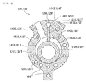
- Fig. 2 is a horizontal cross-sectional view of first and second compressing units according to the example when viewed from above.
- a rotary compressor 1 of the example includes a compressing unit 12 that is disposed in the lower section of a vertically-positioned airtight compressor housing 10 which has a cylindrical shape and a motor 11 that is disposed in the upper section of the compressor housing 10 and drives the compressing unit 12 via a rotation shaft 15.
- a stator 111 of the motor 11 is formed in a cylindrical shape and is shrink-fitted and fixed in the inner circumferential surface of the compressor housing 10.
- a rotor 112 of the motor 11 is disposed inside the cylindrical stator 111 and is shrink-fitted and fixed to the rotation shaft 15 that mechanically connects the motor 11 with the compressing unit 12.
- the compressing unit 12 includes a first compressing unit 12S and a second compressing unit 12T that is disposed in parallel with the first compressing unit 12S and is stacked on the first compressing unit 12S.
- the first and second compressing units 12S and 12T include annular first and second cylinders 121S and 121T in which first and second inlet holes 135S and 135T that are radially disposed and first and second vane grooves 128S and 128T are provided in first and second side-flared portions 122S and 122T.
- first and second cylinder inner walls 123S and 123T are formed in the first and second cylinders 121S and 121T so as to be concentric with the rotation shaft 15 of the motor 11.
- First and second annular pistons 125S and 125T which have an outer diameter smaller than an inner diameter of the cylinder are provided inside the first and second cylinder inner walls 123S and 123T, respectively.
- first and second operation chambers 130S and 130T which suck in, compress, and discharge a refrigerant gas are formed between the first and second cylinder inner walls 123S and 123T and the first and second annular pistons 125S and 125T.
- first and second vane grooves 128S and 128T are formed over the entire cylinder height of the first and second cylinders 121S and 121T in a radial direction from the first and second cylinder inner walls 123S and 123T.
- first and second vanes 127S and 127T are slidably fit in the first and second vane grooves 128S and 128T.
- first and second spring bores 124S and 124T are formed in a deep portion of the first and second vane grooves 128S and 128T such that communication from the outer circumferential portions of the first and second cylinders 121S and 121T to the first and second vane grooves 128S and 128T is performed.
- First and second vane springs (not illustrated) which press the back surface of the first and second vanes 127S and 127T are inserted into the first and second spring bores 124S and 124T.
- the first and second vanes 127S and 127T protrude from the inside of the first and second vane grooves 128S and 128T to the inside of the first and second operation chambers 130S and 130T due to bounces of the first and second vane springs.
- This allows ends of the vanes to come into contact with the outer circumferential surfaces of the first and second annular pistons 125S and 125T and the first and second vanes 127S and 127T to partition the first and second operation chambers 130S and 130T into first and second inlet chambers 131S and 131T and first and second compression chambers 133S and 133T.
- the refrigerant gas compressed in the compressor housing 10 is guided into the first and second cylinders 121S and 121T by communicating the deep portion of the first and second vane grooves 128S and 128T with the inside of the compressor housing 10 via an opening R illustrated in Fig. 1 .
- First and second pressure guiding-in paths 129S and 129T which cause back pressures to be applied by the pressure of the refrigerant gas are formed in the first and second vanes 127S and 127T.
- the first and second inlet holes 135S and 135T which cause the first and second inlet chambers 131S and 131T to communicate with the outside are provided in the first and second cylinders 121S and 121T such that a refrigerant is sucked into the first and second inlet chambers 131S and 131T from the outside.
- an intermediate partition plate 140 is disposed between the first cylinder 121S and the second cylinder 121T and partitions and closes the first operation chamber 130S (refer to Fig. 2 ) of the first cylinder 121S from the second operation chamber 130T (refer to Fig. 2 ) of the second cylinder 121T.
- a lower end plate 160S is disposed on a lower end portion of the first cylinder 121S and closes the first operation chamber 130S of the first cylinder 121S.
- an upper end plate 160T is disposed on an upper end portion of the second cylinder 121T and closes the second operation chamber 130T of the second cylinder 121T.
- a sub-bearing unit 161S is formed on the lower end plate 160S and a sub-shaft unit 151 of the rotation shaft 15 is rotatably supported in the sub-bearing unit 161S.
- a main-bearing unit 161T is formed on the upper end plate 160T and a main-shaft unit 153 of the rotation shaft 15 is rotatably supported in the main-bearing unit 161T.
- the rotation shaft 15 includes a first eccentric portion 152S and a second eccentric portion 152T which are eccentric by a 180° phase shift from each other.
- the first eccentric portion 152S is rotatably fit in the first annular piston 125S of the first compressing unit 12S.
- the second eccentric portion 152T is rotatably fit in the second annular piston 125T of the second compressing unit 12T.
- the first and second annular pistons 125S and 125T make orbital motions inside the first and second cylinders 121S and 121T along the first and second cylinder inner walls 123S and 123T in a counterclockwise direction in Fig. 2 . Accordingly, the first and second vanes 127S and 127T perform reciprocal motions.
- the motions of the first and second annular pistons 125S and 125T and the first and second vanes 127S and 127T cause volumes of the first and second inlet chambers 131S and 131T and the first and second compression chambers 133S and 133T to be continually changed. In this manner, the compressing unit 12 continually sucks in, compresses, and discharges the refrigerant gas.
- a lower muffler cover 170S is disposed on the lower side of the lower end plate 160S and a lower muffler chamber 180S is formed between the lower end plate 160S and the lower muffler cover 170S.
- the first compressing unit 12S opens to the lower muffler chamber 180S. That is, a first outlet 190S (refer to Fig. 2 ) through which the first compression chamber 133S of the first cylinder 121S communicates with the lower muffler chamber 180S is provided in the vicinity of the first vane 127S of the lower end plate 160S.
- a first discharge valve 200S which prevents the compressed refrigerant gas from flowing backward is disposed in the first outlet 190S.
- the lower muffler chamber 180S is a single annular chamber.
- the lower muffler chamber 180S is a part of a communication path through which a discharge side of the first compressing unit 12S communicates with the inside of the upper muffler chamber 180T by passing through a refrigerant path 136 (refer to Fig. 2 ) which penetrates the lower end plate 160S, the first cylinder 121S, the intermediate partition plate 140, the second cylinder 121T and the upper end plate 160T.
- the lower muffler chamber 180S causes pressure pulsation of the discharged refrigerant gas to be reduced.
- a first discharge valve cover 201S which controls an amount of flexural valve opening of the first discharge valve 200S is stacked on the first discharge valve 200S and is fixed to the first discharge valve 200S using a rivet.
- the first outlet 190S, the first discharge valve 200S, and the first discharge valve cover 201S configure a first discharge valve unit of the lower end plate 160S.
- an upper muffler cover 170T is disposed on the upper side of the upper end plate 160T and an upper muffler chamber 180T is formed between the upper end plate 160T and the upper muffler cover 170T.
- a second outlet 190T (refer to Fig. 2 ) through which the second compression chamber 133T of the second cylinder 121T communicates with the upper muffler chamber 180T is provided in the vicinity of the second vane 127T of the upper end plate 160T.
- a reed valve type second discharge valve 200T which prevents the compressed refrigerant gas from flowing backward is disposed in the second outlet 190T.
- a second discharge valve cover 201T which controls an amount of flexural valve opening of the second discharge valve 200T is stacked on the second discharge valve 200T and is fixed using a rivet with the second discharge valve 200T.
- the upper muffler chamber 180T causes pressure pulsation of discharged refrigerant to be reduced.
- the second outlet 190T, the second discharge valve 200T, and the second discharge valve cover 201T configure a second discharge valve unit of the upper end plate 160T.
- the first cylinder 121S, the lower end plate 160S, the lower muffler cover 170S, the second cylinder 121T, the upper end plate 160T, the upper muffler cover 170T, and the intermediate partition plate 140 are integrally fastened using a plurality of penetrating bolts 175 or the like.
- the outer circumferential portion of the upper end plate 160T of the compressing unit 12 which is integrally fastened using the penetrating bolts 175 or the like is firmly fixed to the compressor housing 10 through spot welding. This allows the compressing unit 12 to be fixed to the compressor housing 10.
- First and second through holes 101 and 102 are provided in the outer-side wall of the cylindrical compressor housing 10 at an interval in an axial direction in this order from a lower section thereof so as to communicate with first and second inlet pipes 104 and 105, respectively.
- an accumulator 25 which is formed of a separate airtight cylindrical container is held by an accumulator holder 252 and an accumulator band 253.
- a system connecting pipe 255 which is connected to an evaporator in a refrigeration cycle is connected at the center of the top portion of the accumulator 25.
- First and second low-pressure communication tubes 31S and 31T, each of which has one end extending toward the upward side inside the accumulator 25, and which have the other ends connected to one ends of the first and second inlet pipes 104 and 105, are connected to a bottom through hole 257 provided in the bottom of the accumulator 25.
- the first and second low-pressure communication tubes 31S and 31T which guide a low pressure refrigerant in the refrigeration cycle to the first and second compressing units 12S and 12T via the accumulator 25 are connected to the first and second inlet holes 135S and 135T (refer to Fig. 2 ) of the first and second cylinders 121S and 121T via the first and second inlet pipes 104 and 105 as an inlet unit. That is, the first and second inlet holes 135S and 135T are connected to the evaporator of the refrigeration cycle in parallel.
- a discharge pipe 107 as a discharge portion which is connected to the refrigeration cycle and discharges a high pressure refrigerant gas to a side of a condenser in the refrigeration cycle is connected to the top portion of the compressor housing 10. That is, the first and second outlets 190S and 190T are connected to the condenser in the refrigeration cycle.
- Lubricant oil is sealed in the compressor housing 10 substantially to the elevation of the second cylinder 121T.
- the lubricant oil is sucked up from a lubricating pipe 16 attached to the lower end portion of the rotation shaft 15, using a pump blade (not illustrated) which is inserted into the lower section of the rotation shaft 15.
- the lubricant oil circulates through the compressing unit 12. This allows sliding components to be lubricated and the lubricant oil to seal a fine gap in the compressing unit 12.
- Fig. 3 is a partial cross-sectional view illustrating a sliding portion of the first and second annular pistons and the first and second vanes of Example 1.
- the first and second vanes 127S and 127T of Example 1 have base members, respectively, which are made of steel such as high-speed tool steel (SKH) or stainless steel (SUS).
- SSH high-speed tool steel
- SUS stainless steel
- DLC layers diamond-like carbon layers
- 127SD and 127TD are formed on sliding surfaces (end surfaces) with respect to the first and second annular pistons 125S and 125T, respectively.
- the diamond-like carbon layers (DLC layers) 127SD and 127TD have a diamond bond (SP3: high hardness substance) and a graphite bond (SP2: low hardness and low friction substance).
- SP3 high hardness substance
- SP2 low hardness and low friction substance
- a ratio of a diamond bond (SP3)/ a graphite bond (SP2) of the DLC layers 127SD and 127TD described above is 6 to 10 and micro-Vickers hardness thereof is HmV of 1500 or higher.
- a DLC layer of which a ratio of SP3/SP2 is 5 or less or either a CrN layer or a nitride layer is formed as a joint layer.
- the hardness changes by small degrees between the DLC layer, the joint layer, and the base member and thus, it is possible to improve adhesion of the DLC layer to the base member.
- the first and second annular pistons 125S and 125T of Example 1 are formed using, as a material, Ni-Cr-Mo cast iron to which 0.15 wt% to 0.45 wt% of phosphorus (P) is added.
- P phosphorus
- P+Fe+C very hard steadite
- wear-resistance is improved.
- the upper limit of an amount of phosphorus to be added is set to 0.45 wt%.
- the base members of the first and second annular pistons 125S and 125T may be formed of cast iron or steel and iron nitride layers 125SN and 125TN (refer to Fig. 3 ) may be formed on outer circumferential surfaces of the pistons.
- a nitriding treatment is performed on the first and second annular pistons 125S and 125T and thereby, wear-resistance is improved.
- the nitriding treatment as ion nitriding is performed only on the outer circumferential surfaces.
- the nitriding treatment is not performed on inner circumferential surfaces of the first and second annular pistons 125S and 125T and abnormal wear of the first and second eccentric portions 152S and 152T of the rotation shaft 15 which slide on the inner circumferential surfaces is prevented.
- Fig. 4 is a partial cross-sectional view illustrating a sliding portion of first and second annular pistons and first and second vanes of Example 2.
- the first and second vanes 127S and 127T of Example 2 have base members, respectively, which are made of steel such as high-speed tool steel (SKH) or stainless steel (SUS).
- DLC layers 127SD1 and 127TD1 having HmV of 1500 or higher are formed as under layers on sliding surfaces (end surfaces) with respect to the first and second annular pistons 125S and 125T.
- DLC layers 127SD2 and 127TD2 having HmV of 1200 or lower are formed as fitness layers on the outer sides of the DLC layers 127SD1 and 127TD1 as the under layers.
- the DLC layers 127SD2 and 127TD2 having HmV of 1200 or lower as the fitness layers have the diamond bond (SP3) and the graphite bond (SP2) and a metal or other elements such as tungsten (W), silicon (Si), or nitrogen (n) is added thereto.
- SP3 diamond bond
- SP2 graphite bond
- a metal or other elements such as tungsten (W), silicon (Si), or nitrogen (n) is added thereto.
- a ratio of SP3/SP2 of the DLC layers 127SD1 and 127TD1 having HmV of 1500 or higher as the under layers is 6 to 10.
- the ratio of SP3/SP2 of the DLC layers 127SD2 and 127TD2 having HmV of 1200 or lower as the fitness layers is 5 or less and the DLC layers 127SD2 and 127TD2 may be the soft layers having hardness lower than the under layers.
- the first and second annular pistons 125S and 125T of Example 2 are formed using, as a material, Ni-Cr-Mo cast iron or Ni-Cr-Mo cast iron to which 0.15 wt% to 0.45 wt% of phosphorus (P) is added.
- the base members of the first and second annular pistons 125S and 125T may be formed of cast iron or steel and iron nitride layers 125SN and 125TN (refer to Fig. 4 ) may be formed on outer circumferential surfaces of the pistons. The nitriding treatment as ion nitriding is performed only on the outer circumferential surfaces.
- the nitriding treatment is not performed on inner circumferential surfaces of the first and second annular pistons 125S and 125T and abnormal wear of the first and second eccentric portions 152S and 152T of the rotation shaft 15 which slide on the inner circumferential surfaces is prevented.
- the first and second vanes 127S and 127T of Example 1 or Example 2 which have the sliding surfaces on which the DLC layers are provided and the first and second annular pistons 125S and 125T of Example 1 or Example 2 are combined to be used and thereby, abnormal wear of the first and second annular pistons 125S and 125T does not occur even in a case where a refrigerant discharge temperature of the rotary compressor 1 exceeds 115°C during operation.
Landscapes
- Chemical & Material Sciences (AREA)
- Engineering & Computer Science (AREA)
- Mechanical Engineering (AREA)
- Chemical Kinetics & Catalysis (AREA)
- Materials Engineering (AREA)
- Metallurgy (AREA)
- Organic Chemistry (AREA)
- Inorganic Chemistry (AREA)
- General Engineering & Computer Science (AREA)
- Applications Or Details Of Rotary Compressors (AREA)
Abstract
Description
- The present invention relates to a rotary compressor that is used in an air conditioner or a refrigerating machine.
- In the related art, a compressor (rotary compressor) which is provided in a refrigeration cycle and compresses and circulates a fluorocarbon refrigerant which does not contain chlorine is disclosed, in which, of sliding members which configure a compressing mechanism, a base member of a blade (vane) is made of a ferrous metal, a chromium nitride layer is formed on a surface of the base member, an iron nitride layer which contains chromium nitride is formed as a joint layer between the base member and the chromium nitride layer, and a roller (annular piston) as a counterpart member is formed of Ni-Cr-Mo cast iron (for example, see PTL 1).
- PTL 1:
JP-A-7-217568 - However, when an air conditioner using the rotary compressor in the related art described above is used as a heater at a low outside temperature, the air conditioner is operated under operation conditions of low inlet pressure of a refrigerant, a high compression ratio, and a high discharge temperature. In a case where the rotary compressor is operated with a discharge temperature above 115°C, a problem arises in that abnormal wear of the annular piston made of the Ni-Cr-Mo cast iron occurs.
- The present invention is performed by taking the above problems into account and has an object to achieve a rotary compressor in which abnormal wear of the annular piston does not occur even in a case where a refrigerant discharge temperature of the rotary compressor exceeds 115°C during operation.
- In order to solve the above problems and to achieve the object, a rotary compressor of the present invention includes a compressor housing, a compressing unit, and a motor. The compressor housing is a vertically-positioned airtight compressor housing having an upper section in which a discharge portion of a refrigerant is provided and a lower section in which an inlet unit of the refrigerant is provided on a side surface thereof. The compressing unit is disposed in the lower section of the compressor housing and includes an annular cylinder, an end plate which has a bearing unit and a discharge valve unit and closes an end portion of the cylinder, an annular piston which is fit in an eccentric portion of a rotation shaft supported in the bearing unit, performs an orbital motion inside the cylinder along a cylinder inner wall of the cylinder, and forms an operation chamber together with the cylinder inner wall, and a vane which protrudes from the inside of a vane groove of the cylinder to the inside of the operation chamber, comes into contact with the annular piston, and partitions the operation chamber into an inlet chamber and a compression chamber and the compressing unit performs suction of the refrigerant via the inlet unit and discharges the refrigerant from the discharge portion via the inside of the compressor housing. The motor is disposed in the upper section of the compressor housing and drives the compressing unit via the rotation shaft. Further, the vane is formed of steel and has a diamond-like carbon layer formed on a sliding surface with respect to the annular piston. The annular piston is formed of Ni-Cr-Mo cast iron to which 0.15 wt% to 0.45 wt% of phosphorus is added or the annular piston is formed of cast iron or steel and has an iron nitride layer formed on an outer circumferential surface thereof.
- According to the present invention, the effect that abnormal wear of the annular piston does not occur even in a case where a refrigerant discharge temperature of a rotary compressor exceeds 115°C during operation is achieved.
-
- [
Fig. 1] Fig. 1 is a vertical cross-sectional view illustrating an example of a rotary compressor according to the present invention. - [
Fig. 2] Fig. 2 is a horizontal cross-sectional view of first and second compressing units according to the example when viewed from above. - [
Fig. 3] Fig. 3 is a partial cross-sectional view illustrating a sliding portion of first and second annular pistons and first and second vanes of Example 1. - [
Fig. 4] Fig. 4 is a partial cross-sectional view illustrating a sliding portion of first and second annular pistons and first and second vanes of Example 2. - Hereinafter, an example of a rotary compressor according to the present invention will be described in detail based on the drawings. The invention is not limited to the example.
-
Fig. 1 is a vertical cross-sectional view illustrating an example of a rotary compressor according to the present invention.Fig. 2 is a horizontal cross-sectional view of first and second compressing units according to the example when viewed from above. - As illustrated in
Fig. 1 , a rotary compressor 1 of the example includes acompressing unit 12 that is disposed in the lower section of a vertically-positionedairtight compressor housing 10 which has a cylindrical shape and amotor 11 that is disposed in the upper section of thecompressor housing 10 and drives the compressingunit 12 via arotation shaft 15. - A
stator 111 of themotor 11 is formed in a cylindrical shape and is shrink-fitted and fixed in the inner circumferential surface of thecompressor housing 10. Arotor 112 of themotor 11 is disposed inside thecylindrical stator 111 and is shrink-fitted and fixed to therotation shaft 15 that mechanically connects themotor 11 with the compressingunit 12. - The
compressing unit 12 includes a first compressingunit 12S and a second compressingunit 12T that is disposed in parallel with the first compressingunit 12S and is stacked on the first compressingunit 12S. As illustrated inFig. 2 , the first and second compressingunits second cylinders second inlet holes second vane grooves portions - As illustrated in
Fig. 2 , circular first and second cylinderinner walls second cylinders rotation shaft 15 of themotor 11. First and secondannular pistons inner walls second operation chambers inner walls annular pistons - The first and
second vane grooves second cylinders inner walls second vanes second vane grooves - As illustrated in
Fig. 2 , first andsecond spring bores second vane grooves second cylinders second vane grooves second vanes second spring bores - When the rotary compressor 1 is started, the first and
second vanes second vane grooves second operation chambers annular pistons second vanes second operation chambers second inlet chambers second compression chambers - In addition, the refrigerant gas compressed in the
compressor housing 10 is guided into the first andsecond cylinders second vane grooves compressor housing 10 via an opening R illustrated inFig. 1 . First and second pressure guiding-inpaths second vanes - The first and
second inlet holes second inlet chambers second cylinders second inlet chambers - In addition, as illustrated in
Fig. 1 , anintermediate partition plate 140 is disposed between thefirst cylinder 121S and thesecond cylinder 121T and partitions and closes thefirst operation chamber 130S (refer toFig. 2 ) of thefirst cylinder 121S from thesecond operation chamber 130T (refer toFig. 2 ) of thesecond cylinder 121T. Alower end plate 160S is disposed on a lower end portion of thefirst cylinder 121S and closes thefirst operation chamber 130S of thefirst cylinder 121S. In addition, anupper end plate 160T is disposed on an upper end portion of thesecond cylinder 121T and closes thesecond operation chamber 130T of thesecond cylinder 121T. - A
sub-bearing unit 161S is formed on thelower end plate 160S and asub-shaft unit 151 of therotation shaft 15 is rotatably supported in thesub-bearing unit 161S. A main-bearingunit 161T is formed on theupper end plate 160T and a main-shaft unit 153 of therotation shaft 15 is rotatably supported in the main-bearingunit 161T. - The
rotation shaft 15 includes a firsteccentric portion 152S and a secondeccentric portion 152T which are eccentric by a 180° phase shift from each other. The firsteccentric portion 152S is rotatably fit in the firstannular piston 125S of the first compressingunit 12S. The secondeccentric portion 152T is rotatably fit in the secondannular piston 125T of the secondcompressing unit 12T. - When the
rotation shaft 15 rotates, the first and secondannular pistons second cylinders inner walls Fig. 2 . Accordingly, the first andsecond vanes annular pistons second vanes second inlet chambers second compression chambers unit 12 continually sucks in, compresses, and discharges the refrigerant gas. - As illustrated in
Fig. 1 , alower muffler cover 170S is disposed on the lower side of thelower end plate 160S and alower muffler chamber 180S is formed between thelower end plate 160S and thelower muffler cover 170S. The first compressingunit 12S opens to thelower muffler chamber 180S. That is, afirst outlet 190S (refer toFig. 2 ) through which thefirst compression chamber 133S of thefirst cylinder 121S communicates with thelower muffler chamber 180S is provided in the vicinity of thefirst vane 127S of thelower end plate 160S. Afirst discharge valve 200S which prevents the compressed refrigerant gas from flowing backward is disposed in thefirst outlet 190S. - The
lower muffler chamber 180S is a single annular chamber. Thelower muffler chamber 180S is a part of a communication path through which a discharge side of the first compressingunit 12S communicates with the inside of theupper muffler chamber 180T by passing through a refrigerant path 136 (refer toFig. 2 ) which penetrates thelower end plate 160S, thefirst cylinder 121S, theintermediate partition plate 140, thesecond cylinder 121T and theupper end plate 160T. Thelower muffler chamber 180S causes pressure pulsation of the discharged refrigerant gas to be reduced. A firstdischarge valve cover 201S which controls an amount of flexural valve opening of thefirst discharge valve 200S is stacked on thefirst discharge valve 200S and is fixed to thefirst discharge valve 200S using a rivet. Thefirst outlet 190S, thefirst discharge valve 200S, and the firstdischarge valve cover 201S configure a first discharge valve unit of thelower end plate 160S. - As illustrated in
Fig. 1 , anupper muffler cover 170T is disposed on the upper side of theupper end plate 160T and anupper muffler chamber 180T is formed between theupper end plate 160T and theupper muffler cover 170T. Asecond outlet 190T (refer toFig. 2 ) through which thesecond compression chamber 133T of thesecond cylinder 121T communicates with theupper muffler chamber 180T is provided in the vicinity of thesecond vane 127T of theupper end plate 160T. A reed valve typesecond discharge valve 200T which prevents the compressed refrigerant gas from flowing backward is disposed in thesecond outlet 190T. In addition, a seconddischarge valve cover 201T which controls an amount of flexural valve opening of thesecond discharge valve 200T is stacked on thesecond discharge valve 200T and is fixed using a rivet with thesecond discharge valve 200T. Theupper muffler chamber 180T causes pressure pulsation of discharged refrigerant to be reduced. Thesecond outlet 190T, thesecond discharge valve 200T, and the seconddischarge valve cover 201T configure a second discharge valve unit of theupper end plate 160T. - The
first cylinder 121S, thelower end plate 160S, thelower muffler cover 170S, thesecond cylinder 121T, theupper end plate 160T, theupper muffler cover 170T, and theintermediate partition plate 140 are integrally fastened using a plurality of penetratingbolts 175 or the like. The outer circumferential portion of theupper end plate 160T of the compressingunit 12 which is integrally fastened using the penetratingbolts 175 or the like is firmly fixed to thecompressor housing 10 through spot welding. This allows the compressingunit 12 to be fixed to thecompressor housing 10. - First and second through
holes cylindrical compressor housing 10 at an interval in an axial direction in this order from a lower section thereof so as to communicate with first andsecond inlet pipes compressor housing 10, anaccumulator 25 which is formed of a separate airtight cylindrical container is held by anaccumulator holder 252 and anaccumulator band 253. - A
system connecting pipe 255 which is connected to an evaporator in a refrigeration cycle is connected at the center of the top portion of theaccumulator 25. First and second low-pressure communication tubes accumulator 25, and which have the other ends connected to one ends of the first andsecond inlet pipes hole 257 provided in the bottom of theaccumulator 25. - The first and second low-
pressure communication tubes second compressing units accumulator 25 are connected to the first and second inlet holes 135S and 135T (refer toFig. 2 ) of the first andsecond cylinders second inlet pipes - A
discharge pipe 107 as a discharge portion which is connected to the refrigeration cycle and discharges a high pressure refrigerant gas to a side of a condenser in the refrigeration cycle is connected to the top portion of thecompressor housing 10. That is, the first andsecond outlets - Lubricant oil is sealed in the
compressor housing 10 substantially to the elevation of thesecond cylinder 121T. In addition, the lubricant oil is sucked up from a lubricatingpipe 16 attached to the lower end portion of therotation shaft 15, using a pump blade (not illustrated) which is inserted into the lower section of therotation shaft 15. The lubricant oil circulates through the compressingunit 12. This allows sliding components to be lubricated and the lubricant oil to seal a fine gap in the compressingunit 12. - Next, a characteristic configuration of the rotary compressor of the example will be described with reference to
Fig. 3. Fig. 3 is a partial cross-sectional view illustrating a sliding portion of the first and second annular pistons and the first and second vanes of Example 1. As illustrated inFig. 3 , the first andsecond vanes annular pistons - Even though wear-resistance is improved by the DLC layer, insufficient adhesion between the DLC layer and the base member results in peeling-off of the DLC layer. Hence, between the DLC layer and the base member, a DLC layer of which a ratio of SP3/SP2 is 5 or less or either a CrN layer or a nitride layer is formed as a joint layer. When the joint layer is formed, the hardness changes by small degrees between the DLC layer, the joint layer, and the base member and thus, it is possible to improve adhesion of the DLC layer to the base member.
- The first and second
annular pistons - In addition, the base members of the first and second
annular pistons Fig. 3 ) may be formed on outer circumferential surfaces of the pistons. A nitriding treatment is performed on the first and secondannular pistons annular pistons eccentric portions rotation shaft 15 which slide on the inner circumferential surfaces is prevented. - Next, a characteristic configuration of the rotary compressor of Example 2 will be described with reference to
Fig. 4. Fig. 4 is a partial cross-sectional view illustrating a sliding portion of first and second annular pistons and first and second vanes of Example 2. As illustrated inFig. 4 , the first andsecond vanes annular pistons - The DLC layers 127SD2 and 127TD2 having HmV of 1200 or lower as the fitness layers have the diamond bond (SP3) and the graphite bond (SP2) and a metal or other elements such as tungsten (W), silicon (Si), or nitrogen (n) is added thereto. In this manner, the hardness is further decreased than the under layers and the fitness layer becomes a soft layer, wear of the soft layer due to sliding causes a fine protrusion to be removed or one-side contact not to occur, surface pressure during the sliding is decreased, and seizing or abnormal wear is prevented.
- In addition, a ratio of SP3/SP2 of the DLC layers 127SD1 and 127TD1 having HmV of 1500 or higher as the under layers is 6 to 10. The ratio of SP3/SP2 of the DLC layers 127SD2 and 127TD2 having HmV of 1200 or lower as the fitness layers is 5 or less and the DLC layers 127SD2 and 127TD2 may be the soft layers having hardness lower than the under layers.
- Even though wear-resistance is improved by the DLC layer, insufficient adhesion between the DLC layer and the base member results in peeling-off of the DLC layer. Hence, between the DLC layer and the base member, a DLC layer of which a ratio of SP3/SP2 is 5 or less or either a CrN layer or a nitride layer is formed as a joint layer. In this manner, it is possible to improve adhesion of the DLC layer to the base member.
- The first and second
annular pistons annular pistons Fig. 4 ) may be formed on outer circumferential surfaces of the pistons. The nitriding treatment as ion nitriding is performed only on the outer circumferential surfaces. The nitriding treatment is not performed on inner circumferential surfaces of the first and secondannular pistons eccentric portions rotation shaft 15 which slide on the inner circumferential surfaces is prevented. - The first and
second vanes annular pistons annular pistons -
- 1
- rotary compressor
- 10
- compressor housing
- 11
- motor
- 12
- compressing unit
- 15
- rotation shaft
- 16
- lubricating pipe
- 25
- accumulator
- 31S
- first low-pressure communication tube
- 31T
- second low-pressure communication tube
- 101
- first through hole
- 102
- second through hole
- 104
- first inlet pipe
- 105
- second inlet pipe
- 107
- discharge pipe (discharge portion)
- 111
- stator
- 112
- rotor
- 12S
- first compressing unit
- 12T
- second compressing unit
- 121S
- first cylinder (cylinder)
- 121T
- second cylinder (cylinder)
- 122S
- first side-flared portion
- 122T
- second side-flared portion
- 123S
- first cylinder inner wall (cylinder inner wall)
- 123T
- second cylinder inner wall (cylinder inner wall)
- 124S
- first spring bore
- 124T
- second spring bore
- 125S
- first annular piston (annular piston)
- 125T
- second annular piston (annular piston)
- 125SN, 125TN
- iron nitride layer
- 127S
- first vane (vane)
- 127T
- second vane (vane)
- 127SD, 127TD
- diamond-like carbon layer (DLC layer)
- 127SD1, 127TD1
- under layer (DLC layer)
- 127SD2, 127TD2
- fitness layer (DLC layer)
- 128S
- first vane groove (vane groove)
- 128T
- second vane groove (vane groove)
- 129S
- first pressure guiding-in path
- 129T
- second pressure guiding-in path
- 130S
- first operation chamber (operation chamber)
- 130T
- second operation chamber (operation chamber)
- 131S
- first inlet chamber (inlet chamber)
- 131T
- second inlet chamber (inlet chamber)
- 133S
- first compression chamber (compression chamber)
- 133T
- second compression chamber (compression chamber)
- 135S
- first inlet hole (inlet hole)
- 135T
- second inlet hole (inlet hole)
- 136
- refrigerant path
- 140
- intermediate partition plate
- 151
- sub-shaft unit
- 152S
- first eccentric portion (eccentric portion)
- 152T
- second eccentric portion (eccentric portion)
- 153
- main-shaft unit
- 160S
- lower end plate (end plate)
- 160T
- upper end plate (end plate)
- 161S
- sub-bearing unit
- 161T
- main-bearing unit
- 170S
- lower muffler cover
- 170T
- upper muffler cover
- 175
- penetrating bolt
- 180S
- lower muffler chamber
- 180T
- upper muffler chamber
- 190S
- first outlet (outlet)
- 190T
- second outlet (outlet)
- 200S
- first discharge valve
- 200T
- second discharge valve
- 201S
- first discharge valve cover
- 201T
- second discharge valve cover
- 252
- accumulator holder
- 253
- accumulator band
- 255
- system connecting pipe
- R
- opening
Claims (5)
- A rotary compressor characterized by comprising:a vertically-positioned airtight compressor housing having an upper section in which a discharge portion of a refrigerant is provided and a lower section in which an inlet unit of the refrigerant is provided on a side surface thereof;a compressing unit that is disposed in the lower section of the compressor housing, that includes an annular cylinder, an end plate which has a bearing unit and a discharge valve unit and closes an end portion of the cylinder, an annular piston which is fit in an eccentric portion of a rotation shaft supported in the bearing unit, performs an orbital motion inside the cylinder along a cylinder inner wall of the cylinder, and forms an operation chamber together with the cylinder inner wall, and a vane which protrudes from the inside of a vane groove of the cylinder to the inside of the operation chamber, comes into contact with the annular piston, and partitions the operation chamber into an inlet chamber and a compression chamber, and that performs suction of the refrigerant via the inlet unit and discharges the refrigerant from the discharge portion via the inside of the compressor housing; anda motor that is disposed in the upper section of the compressor housing and drives the compressing unit via the rotation shaft,wherein the vane is formed of steel and has a diamond-like carbon layer formed on a sliding surface with respect to the annular piston, andwherein the annular piston is formed of Ni-Cr-Mo cast iron to which 0.15 wt% to 0.45 wt% of phosphorus is added, or is formed of cast iron or steel and has an iron nitride layer formed on an outer circumferential surface thereof.
- The rotary compressor according to Claim 1, characterized in that
between a base member and the diamond-like carbon layer of the vane, any one layer of a layer of which a ratio of SP3/SP2 is 5 or less, a CrN layer, and a nitride layer is formed as a joint layer. - A rotary compressor characterized by comprising:a vertically-positioned airtight compressor housing having an upper section in which a discharge portion of a refrigerant is provided and a lower section in which an inlet unit of the refrigerant is provided on a side surface thereof;a compressing unit that is disposed in the lower section of the compressor housing, that includes an annular cylinder, an end plate which has a bearing unit and a discharge valve unit and closes an end portion of the cylinder, an annular piston which is fit in an eccentric portion of a rotation shaft supported in the bearing unit, performs an orbital motion inside the cylinder along a cylinder inner wall of the cylinder, and forms an operation chamber together with the cylinder inner wall, and a vane which protrudes from the inside of a vane groove of the cylinder to the inside of the operation chamber, comes into contact with the annular piston, and partitions the operation chamber into an inlet chamber and a compression chamber, and that performs suction of the refrigerant via the inlet unit and discharges the refrigerant from the discharge portion via the inside of the compressor housing; anda motor that is disposed in the upper section of the compressor housing and drives the compressing unit via the rotation shaft,wherein the vane is formed of steel and has a diamond-like carbon layer having HmV of 1500 or higher which is formed as an under layer on a sliding surface with respect to the annular piston and a diamond-like carbon layer having HmV of 1200 or lower which is formed as a fitness layer on an outer side of the diamond-like carbon layer having HmV of 1500 or higher, andwherein the annular piston is formed of Ni-Cr-Mo cast iron or Ni-Cr-Mo cast iron to which 0.15 wt% to 0.45 wt% of phosphorus is added, or is formed of cast iron or steel and has an iron nitride layer formed on an outer circumferential surface thereof.
- The rotary compressor according to Claim 3, characterized in that
between a base member and the diamond-like carbon layer having HmV of 1500 or higher as the under layer of the vane, any one layer of a layer of which a ratio of SP3/SP2 is 5 or less, a CrN layer, and a nitride layer is formed as a joint layer. - The rotary compressor according to Claim 3, characterized in that
the diamond-like carbon layer having HmV of 1200 or lower as the fitness layer is formed by adding a metal or other elements thereto in addition to having a diamond bond and a graphite bond.
Applications Claiming Priority (2)
| Application Number | Priority Date | Filing Date | Title |
|---|---|---|---|
| JP2013205825A JP5652527B1 (en) | 2013-09-30 | 2013-09-30 | Rotary compressor |
| PCT/JP2014/051981 WO2015045433A1 (en) | 2013-09-30 | 2014-01-29 | Rotary compressor |
Publications (3)
| Publication Number | Publication Date |
|---|---|
| EP3054163A1 true EP3054163A1 (en) | 2016-08-10 |
| EP3054163A4 EP3054163A4 (en) | 2017-05-03 |
| EP3054163B1 EP3054163B1 (en) | 2019-10-09 |
Family
ID=52339814
Family Applications (1)
| Application Number | Title | Priority Date | Filing Date |
|---|---|---|---|
| EP14849885.0A Active EP3054163B1 (en) | 2013-09-30 | 2014-01-29 | Rotary compressor |
Country Status (6)
| Country | Link |
|---|---|
| US (1) | US9890786B2 (en) |
| EP (1) | EP3054163B1 (en) |
| JP (1) | JP5652527B1 (en) |
| CN (1) | CN105164421B (en) |
| AU (1) | AU2014325844B2 (en) |
| WO (1) | WO2015045433A1 (en) |
Families Citing this family (9)
| Publication number | Priority date | Publication date | Assignee | Title |
|---|---|---|---|---|
| JP2017014990A (en) * | 2015-06-30 | 2017-01-19 | 株式会社富士通ゼネラル | Rotary Compressor |
| JP2017031830A (en) * | 2015-07-29 | 2017-02-09 | 株式会社富士通ゼネラル | Rotary Compressor |
| DE102016105247A1 (en) | 2016-03-21 | 2017-09-21 | Schwäbische Hüttenwerke Automotive GmbH | CONVEYOR FOR A ROTATION PUMP |
| JP6834388B2 (en) * | 2016-11-16 | 2021-02-24 | 株式会社富士通ゼネラル | Rotary compressor |
| KR102554929B1 (en) * | 2018-10-19 | 2023-07-11 | 현대자동차주식회사 | Engine piston and manufacturing method thereof |
| JP6988940B2 (en) | 2020-03-30 | 2022-01-05 | 株式会社富士通ゼネラル | Rotary compressor |
| CN113638883A (en) * | 2021-09-23 | 2021-11-12 | 珠海格力节能环保制冷技术研究中心有限公司 | Pump body subassembly, compressor and air conditioner |
| US12038005B2 (en) | 2022-02-10 | 2024-07-16 | Samsung Electronics Co., Ltd. | Moving part, compressor, and manufacturing method thereof |
| CN114962261A (en) * | 2022-06-20 | 2022-08-30 | 珠海格力电器股份有限公司 | Pump body assembly, compressor and air conditioner with same |
Family Cites Families (18)
| Publication number | Priority date | Publication date | Assignee | Title |
|---|---|---|---|---|
| JPH05312168A (en) * | 1992-05-08 | 1993-11-22 | Matsushita Refrig Co Ltd | Compressor |
| JPH07217568A (en) | 1994-02-04 | 1995-08-15 | Toshiba Corp | compressor |
| JPH1082390A (en) * | 1996-07-18 | 1998-03-31 | Sanyo Electric Co Ltd | Sliding member, compressor and rotary compressor |
| US6066399A (en) | 1997-03-19 | 2000-05-23 | Sanyo Electric Co., Ltd. | Hard carbon thin film and method of forming the same |
| JPH11264393A (en) * | 1998-03-18 | 1999-09-28 | Sanyo Electric Co Ltd | Vane and refrigerant compressor using the same |
| JP4374153B2 (en) * | 2001-06-29 | 2009-12-02 | 日本ピストンリング株式会社 | piston ring |
| TW568996B (en) | 2001-11-19 | 2004-01-01 | Sanyo Electric Co | Defroster of refrigerant circuit and rotary compressor for refrigerant circuit |
| JP2006077582A (en) | 2004-09-07 | 2006-03-23 | Mitsubishi Electric Corp | Rotary compressor |
| JP2007162099A (en) | 2005-12-15 | 2007-06-28 | Toyota Motor Corp | Hard carbon film, method for producing the same, and sliding member |
| JP2009167512A (en) * | 2008-01-21 | 2009-07-30 | Kobe Steel Ltd | Diamond-like carbon film for sliding component and method for manufacturing the same |
| US8585385B2 (en) * | 2008-03-21 | 2013-11-19 | Toshiba Carrier Corporation | Refrigerant compressor and refrigerating cycle device |
| JP5182130B2 (en) | 2008-12-24 | 2013-04-10 | 株式会社豊田自動織機 | Sliding member in compressor |
| JP2011001598A (en) * | 2009-06-18 | 2011-01-06 | Jtekt Corp | Sliding member |
| JP2011001897A (en) | 2009-06-19 | 2011-01-06 | Panasonic Corp | Compressor |
| JP4862925B2 (en) * | 2009-07-31 | 2012-01-25 | 株式会社富士通ゼネラル | Rotary compressor |
| JP2014095291A (en) | 2011-02-28 | 2014-05-22 | Sanyo Electric Co Ltd | Rotary compressor |
| JP5870246B2 (en) | 2011-05-10 | 2016-02-24 | パナソニックIpマネジメント株式会社 | Rotary compressor |
| CN202483876U (en) | 2011-12-02 | 2012-10-10 | 广东美芝制冷设备有限公司 | Rolling rotor compressor |
-
2013
- 2013-09-30 JP JP2013205825A patent/JP5652527B1/en active Active
-
2014
- 2014-01-29 AU AU2014325844A patent/AU2014325844B2/en not_active Ceased
- 2014-01-29 US US14/898,042 patent/US9890786B2/en active Active
- 2014-01-29 WO PCT/JP2014/051981 patent/WO2015045433A1/en not_active Ceased
- 2014-01-29 CN CN201480025089.5A patent/CN105164421B/en active Active
- 2014-01-29 EP EP14849885.0A patent/EP3054163B1/en active Active
Also Published As
| Publication number | Publication date |
|---|---|
| US9890786B2 (en) | 2018-02-13 |
| WO2015045433A1 (en) | 2015-04-02 |
| US20160138593A1 (en) | 2016-05-19 |
| JP2015068324A (en) | 2015-04-13 |
| CN105164421A (en) | 2015-12-16 |
| AU2014325844B2 (en) | 2016-10-20 |
| EP3054163A4 (en) | 2017-05-03 |
| JP5652527B1 (en) | 2015-01-14 |
| AU2014325844A1 (en) | 2015-12-17 |
| EP3054163B1 (en) | 2019-10-09 |
| CN105164421B (en) | 2017-05-17 |
Similar Documents
| Publication | Publication Date | Title |
|---|---|---|
| EP3054163B1 (en) | Rotary compressor | |
| JP6015055B2 (en) | Rotary compressor | |
| EP3112587B1 (en) | Rotary compressor | |
| EP3043070B1 (en) | Rotary compressor | |
| JP5998522B2 (en) | Rotary compressor | |
| JP2017031831A (en) | Rotary compressor | |
| EP3054164B1 (en) | Rotary compressor | |
| JP2017031830A (en) | Rotary Compressor | |
| JP6201341B2 (en) | Rotary compressor | |
| JP2012207585A (en) | Rotary compressor | |
| JP2017053361A (en) | Rotary compressor | |
| AU2015224264A1 (en) | Rotary compressor | |
| JP6064726B2 (en) | Rotary compressor | |
| JP6064719B2 (en) | Rotary compressor | |
| JP2016089811A (en) | Rotary compressor | |
| JP6111695B2 (en) | Rotary compressor | |
| JP6011647B2 (en) | Rotary compressor | |
| JP2014015850A (en) | Rotary compressor |
Legal Events
| Date | Code | Title | Description |
|---|---|---|---|
| PUAI | Public reference made under article 153(3) epc to a published international application that has entered the european phase |
Free format text: ORIGINAL CODE: 0009012 |
|
| 17P | Request for examination filed |
Effective date: 20151214 |
|
| AK | Designated contracting states |
Kind code of ref document: A1 Designated state(s): AL AT BE BG CH CY CZ DE DK EE ES FI FR GB GR HR HU IE IS IT LI LT LU LV MC MK MT NL NO PL PT RO RS SE SI SK SM TR |
|
| AX | Request for extension of the european patent |
Extension state: BA ME |
|
| DAX | Request for extension of the european patent (deleted) | ||
| A4 | Supplementary search report drawn up and despatched |
Effective date: 20170405 |
|
| RIC1 | Information provided on ipc code assigned before grant |
Ipc: F04C 23/00 20060101ALN20170329BHEP Ipc: F04C 18/356 20060101AFI20170329BHEP Ipc: C23C 28/00 20060101ALI20170329BHEP Ipc: F01C 21/08 20060101ALI20170329BHEP |
|
| STAA | Information on the status of an ep patent application or granted ep patent |
Free format text: STATUS: EXAMINATION IS IN PROGRESS |
|
| 17Q | First examination report despatched |
Effective date: 20180517 |
|
| GRAP | Despatch of communication of intention to grant a patent |
Free format text: ORIGINAL CODE: EPIDOSNIGR1 |
|
| STAA | Information on the status of an ep patent application or granted ep patent |
Free format text: STATUS: GRANT OF PATENT IS INTENDED |
|
| RIC1 | Information provided on ipc code assigned before grant |
Ipc: C23C 28/00 20060101ALI20190319BHEP Ipc: F04C 18/356 20060101AFI20190319BHEP Ipc: F04C 23/00 20060101ALN20190319BHEP Ipc: F01C 21/08 20060101ALI20190319BHEP |
|
| INTG | Intention to grant announced |
Effective date: 20190411 |
|
| GRAS | Grant fee paid |
Free format text: ORIGINAL CODE: EPIDOSNIGR3 |
|
| GRAJ | Information related to disapproval of communication of intention to grant by the applicant or resumption of examination proceedings by the epo deleted |
Free format text: ORIGINAL CODE: EPIDOSDIGR1 |
|
| GRAL | Information related to payment of fee for publishing/printing deleted |
Free format text: ORIGINAL CODE: EPIDOSDIGR3 |
|
| STAA | Information on the status of an ep patent application or granted ep patent |
Free format text: STATUS: EXAMINATION IS IN PROGRESS |
|
| GRAR | Information related to intention to grant a patent recorded |
Free format text: ORIGINAL CODE: EPIDOSNIGR71 |
|
| STAA | Information on the status of an ep patent application or granted ep patent |
Free format text: STATUS: GRANT OF PATENT IS INTENDED |
|
| INTC | Intention to grant announced (deleted) | ||
| RIC1 | Information provided on ipc code assigned before grant |
Ipc: F04C 18/356 20060101AFI20190729BHEP Ipc: F04C 23/00 20060101ALN20190729BHEP Ipc: F01C 21/08 20060101ALI20190729BHEP Ipc: C23C 28/00 20060101ALI20190729BHEP |
|
| GRAA | (expected) grant |
Free format text: ORIGINAL CODE: 0009210 |
|
| STAA | Information on the status of an ep patent application or granted ep patent |
Free format text: STATUS: THE PATENT HAS BEEN GRANTED |
|
| INTG | Intention to grant announced |
Effective date: 20190829 |
|
| AK | Designated contracting states |
Kind code of ref document: B1 Designated state(s): AL AT BE BG CH CY CZ DE DK EE ES FI FR GB GR HR HU IE IS IT LI LT LU LV MC MK MT NL NO PL PT RO RS SE SI SK SM TR |
|
| REG | Reference to a national code |
Ref country code: GB Ref legal event code: FG4D |
|
| REG | Reference to a national code |
Ref country code: CH Ref legal event code: EP |
|
| REG | Reference to a national code |
Ref country code: IE Ref legal event code: FG4D |
|
| REG | Reference to a national code |
Ref country code: DE Ref legal event code: R096 Ref document number: 602014055044 Country of ref document: DE |
|
| REG | Reference to a national code |
Ref country code: AT Ref legal event code: REF Ref document number: 1189137 Country of ref document: AT Kind code of ref document: T Effective date: 20191115 |
|
| REG | Reference to a national code |
Ref country code: NL Ref legal event code: MP Effective date: 20191009 |
|
| REG | Reference to a national code |
Ref country code: LT Ref legal event code: MG4D |
|
| REG | Reference to a national code |
Ref country code: AT Ref legal event code: MK05 Ref document number: 1189137 Country of ref document: AT Kind code of ref document: T Effective date: 20191009 |
|
| PG25 | Lapsed in a contracting state [announced via postgrant information from national office to epo] |
Ref country code: SE Free format text: LAPSE BECAUSE OF FAILURE TO SUBMIT A TRANSLATION OF THE DESCRIPTION OR TO PAY THE FEE WITHIN THE PRESCRIBED TIME-LIMIT Effective date: 20191009 Ref country code: AT Free format text: LAPSE BECAUSE OF FAILURE TO SUBMIT A TRANSLATION OF THE DESCRIPTION OR TO PAY THE FEE WITHIN THE PRESCRIBED TIME-LIMIT Effective date: 20191009 Ref country code: LV Free format text: LAPSE BECAUSE OF FAILURE TO SUBMIT A TRANSLATION OF THE DESCRIPTION OR TO PAY THE FEE WITHIN THE PRESCRIBED TIME-LIMIT Effective date: 20191009 Ref country code: FI Free format text: LAPSE BECAUSE OF FAILURE TO SUBMIT A TRANSLATION OF THE DESCRIPTION OR TO PAY THE FEE WITHIN THE PRESCRIBED TIME-LIMIT Effective date: 20191009 Ref country code: GR Free format text: LAPSE BECAUSE OF FAILURE TO SUBMIT A TRANSLATION OF THE DESCRIPTION OR TO PAY THE FEE WITHIN THE PRESCRIBED TIME-LIMIT Effective date: 20200110 Ref country code: BG Free format text: LAPSE BECAUSE OF FAILURE TO SUBMIT A TRANSLATION OF THE DESCRIPTION OR TO PAY THE FEE WITHIN THE PRESCRIBED TIME-LIMIT Effective date: 20200109 Ref country code: NO Free format text: LAPSE BECAUSE OF FAILURE TO SUBMIT A TRANSLATION OF THE DESCRIPTION OR TO PAY THE FEE WITHIN THE PRESCRIBED TIME-LIMIT Effective date: 20200109 Ref country code: PL Free format text: LAPSE BECAUSE OF FAILURE TO SUBMIT A TRANSLATION OF THE DESCRIPTION OR TO PAY THE FEE WITHIN THE PRESCRIBED TIME-LIMIT Effective date: 20191009 Ref country code: NL Free format text: LAPSE BECAUSE OF FAILURE TO SUBMIT A TRANSLATION OF THE DESCRIPTION OR TO PAY THE FEE WITHIN THE PRESCRIBED TIME-LIMIT Effective date: 20191009 Ref country code: PT Free format text: LAPSE BECAUSE OF FAILURE TO SUBMIT A TRANSLATION OF THE DESCRIPTION OR TO PAY THE FEE WITHIN THE PRESCRIBED TIME-LIMIT Effective date: 20200210 Ref country code: ES Free format text: LAPSE BECAUSE OF FAILURE TO SUBMIT A TRANSLATION OF THE DESCRIPTION OR TO PAY THE FEE WITHIN THE PRESCRIBED TIME-LIMIT Effective date: 20191009 Ref country code: LT Free format text: LAPSE BECAUSE OF FAILURE TO SUBMIT A TRANSLATION OF THE DESCRIPTION OR TO PAY THE FEE WITHIN THE PRESCRIBED TIME-LIMIT Effective date: 20191009 |
|
| PG25 | Lapsed in a contracting state [announced via postgrant information from national office to epo] |
Ref country code: HR Free format text: LAPSE BECAUSE OF FAILURE TO SUBMIT A TRANSLATION OF THE DESCRIPTION OR TO PAY THE FEE WITHIN THE PRESCRIBED TIME-LIMIT Effective date: 20191009 Ref country code: IS Free format text: LAPSE BECAUSE OF FAILURE TO SUBMIT A TRANSLATION OF THE DESCRIPTION OR TO PAY THE FEE WITHIN THE PRESCRIBED TIME-LIMIT Effective date: 20200224 Ref country code: RS Free format text: LAPSE BECAUSE OF FAILURE TO SUBMIT A TRANSLATION OF THE DESCRIPTION OR TO PAY THE FEE WITHIN THE PRESCRIBED TIME-LIMIT Effective date: 20191009 |
|
| PG25 | Lapsed in a contracting state [announced via postgrant information from national office to epo] |
Ref country code: AL Free format text: LAPSE BECAUSE OF FAILURE TO SUBMIT A TRANSLATION OF THE DESCRIPTION OR TO PAY THE FEE WITHIN THE PRESCRIBED TIME-LIMIT Effective date: 20191009 |
|
| REG | Reference to a national code |
Ref country code: DE Ref legal event code: R097 Ref document number: 602014055044 Country of ref document: DE |
|
| PG2D | Information on lapse in contracting state deleted |
Ref country code: IS |
|
| PG25 | Lapsed in a contracting state [announced via postgrant information from national office to epo] |
Ref country code: EE Free format text: LAPSE BECAUSE OF FAILURE TO SUBMIT A TRANSLATION OF THE DESCRIPTION OR TO PAY THE FEE WITHIN THE PRESCRIBED TIME-LIMIT Effective date: 20191009 Ref country code: CZ Free format text: LAPSE BECAUSE OF FAILURE TO SUBMIT A TRANSLATION OF THE DESCRIPTION OR TO PAY THE FEE WITHIN THE PRESCRIBED TIME-LIMIT Effective date: 20191009 Ref country code: RO Free format text: LAPSE BECAUSE OF FAILURE TO SUBMIT A TRANSLATION OF THE DESCRIPTION OR TO PAY THE FEE WITHIN THE PRESCRIBED TIME-LIMIT Effective date: 20191009 Ref country code: DK Free format text: LAPSE BECAUSE OF FAILURE TO SUBMIT A TRANSLATION OF THE DESCRIPTION OR TO PAY THE FEE WITHIN THE PRESCRIBED TIME-LIMIT Effective date: 20191009 Ref country code: IS Free format text: LAPSE BECAUSE OF FAILURE TO SUBMIT A TRANSLATION OF THE DESCRIPTION OR TO PAY THE FEE WITHIN THE PRESCRIBED TIME-LIMIT Effective date: 20200209 |
|
| PLBE | No opposition filed within time limit |
Free format text: ORIGINAL CODE: 0009261 |
|
| STAA | Information on the status of an ep patent application or granted ep patent |
Free format text: STATUS: NO OPPOSITION FILED WITHIN TIME LIMIT |
|
| PG25 | Lapsed in a contracting state [announced via postgrant information from national office to epo] |
Ref country code: SM Free format text: LAPSE BECAUSE OF FAILURE TO SUBMIT A TRANSLATION OF THE DESCRIPTION OR TO PAY THE FEE WITHIN THE PRESCRIBED TIME-LIMIT Effective date: 20191009 Ref country code: IT Free format text: LAPSE BECAUSE OF FAILURE TO SUBMIT A TRANSLATION OF THE DESCRIPTION OR TO PAY THE FEE WITHIN THE PRESCRIBED TIME-LIMIT Effective date: 20191009 Ref country code: MC Free format text: LAPSE BECAUSE OF FAILURE TO SUBMIT A TRANSLATION OF THE DESCRIPTION OR TO PAY THE FEE WITHIN THE PRESCRIBED TIME-LIMIT Effective date: 20191009 Ref country code: SK Free format text: LAPSE BECAUSE OF FAILURE TO SUBMIT A TRANSLATION OF THE DESCRIPTION OR TO PAY THE FEE WITHIN THE PRESCRIBED TIME-LIMIT Effective date: 20191009 |
|
| REG | Reference to a national code |
Ref country code: CH Ref legal event code: PL |
|
| 26N | No opposition filed |
Effective date: 20200710 |
|
| REG | Reference to a national code |
Ref country code: BE Ref legal event code: MM Effective date: 20200131 |
|
| PG25 | Lapsed in a contracting state [announced via postgrant information from national office to epo] |
Ref country code: LU Free format text: LAPSE BECAUSE OF NON-PAYMENT OF DUE FEES Effective date: 20200129 |
|
| PG25 | Lapsed in a contracting state [announced via postgrant information from national office to epo] |
Ref country code: BE Free format text: LAPSE BECAUSE OF NON-PAYMENT OF DUE FEES Effective date: 20200131 Ref country code: SI Free format text: LAPSE BECAUSE OF FAILURE TO SUBMIT A TRANSLATION OF THE DESCRIPTION OR TO PAY THE FEE WITHIN THE PRESCRIBED TIME-LIMIT Effective date: 20191009 Ref country code: LI Free format text: LAPSE BECAUSE OF NON-PAYMENT OF DUE FEES Effective date: 20200131 Ref country code: CH Free format text: LAPSE BECAUSE OF NON-PAYMENT OF DUE FEES Effective date: 20200131 |
|
| PG25 | Lapsed in a contracting state [announced via postgrant information from national office to epo] |
Ref country code: IE Free format text: LAPSE BECAUSE OF NON-PAYMENT OF DUE FEES Effective date: 20200129 |
|
| PG25 | Lapsed in a contracting state [announced via postgrant information from national office to epo] |
Ref country code: TR Free format text: LAPSE BECAUSE OF FAILURE TO SUBMIT A TRANSLATION OF THE DESCRIPTION OR TO PAY THE FEE WITHIN THE PRESCRIBED TIME-LIMIT Effective date: 20191009 Ref country code: MT Free format text: LAPSE BECAUSE OF FAILURE TO SUBMIT A TRANSLATION OF THE DESCRIPTION OR TO PAY THE FEE WITHIN THE PRESCRIBED TIME-LIMIT Effective date: 20191009 Ref country code: CY Free format text: LAPSE BECAUSE OF FAILURE TO SUBMIT A TRANSLATION OF THE DESCRIPTION OR TO PAY THE FEE WITHIN THE PRESCRIBED TIME-LIMIT Effective date: 20191009 |
|
| PG25 | Lapsed in a contracting state [announced via postgrant information from national office to epo] |
Ref country code: MK Free format text: LAPSE BECAUSE OF FAILURE TO SUBMIT A TRANSLATION OF THE DESCRIPTION OR TO PAY THE FEE WITHIN THE PRESCRIBED TIME-LIMIT Effective date: 20191009 |
|
| PGFP | Annual fee paid to national office [announced via postgrant information from national office to epo] |
Ref country code: GB Payment date: 20221208 Year of fee payment: 10 Ref country code: FR Payment date: 20221208 Year of fee payment: 10 |
|
| PGFP | Annual fee paid to national office [announced via postgrant information from national office to epo] |
Ref country code: DE Payment date: 20221207 Year of fee payment: 10 |
|
| REG | Reference to a national code |
Ref country code: DE Ref legal event code: R119 Ref document number: 602014055044 Country of ref document: DE |
|
| GBPC | Gb: european patent ceased through non-payment of renewal fee |
Effective date: 20240129 |
|
| PG25 | Lapsed in a contracting state [announced via postgrant information from national office to epo] |
Ref country code: DE Free format text: LAPSE BECAUSE OF NON-PAYMENT OF DUE FEES Effective date: 20240801 |
|
| PG25 | Lapsed in a contracting state [announced via postgrant information from national office to epo] |
Ref country code: GB Free format text: LAPSE BECAUSE OF NON-PAYMENT OF DUE FEES Effective date: 20240129 |
|
| PG25 | Lapsed in a contracting state [announced via postgrant information from national office to epo] |
Ref country code: FR Free format text: LAPSE BECAUSE OF NON-PAYMENT OF DUE FEES Effective date: 20240131 |
|
| PG25 | Lapsed in a contracting state [announced via postgrant information from national office to epo] |
Ref country code: GB Free format text: LAPSE BECAUSE OF NON-PAYMENT OF DUE FEES Effective date: 20240129 Ref country code: FR Free format text: LAPSE BECAUSE OF NON-PAYMENT OF DUE FEES Effective date: 20240131 Ref country code: DE Free format text: LAPSE BECAUSE OF NON-PAYMENT OF DUE FEES Effective date: 20240801 |