EP3054104A2 - Vane stages - Google Patents
Vane stages Download PDFInfo
- Publication number
- EP3054104A2 EP3054104A2 EP16154554.6A EP16154554A EP3054104A2 EP 3054104 A2 EP3054104 A2 EP 3054104A2 EP 16154554 A EP16154554 A EP 16154554A EP 3054104 A2 EP3054104 A2 EP 3054104A2
- Authority
- EP
- European Patent Office
- Prior art keywords
- seal carrier
- platform
- flanges
- vane
- holes
- Prior art date
- Legal status (The legal status is an assumption and is not a legal conclusion. Google has not performed a legal analysis and makes no representation as to the accuracy of the status listed.)
- Granted
Links
Images
Classifications
-
- F—MECHANICAL ENGINEERING; LIGHTING; HEATING; WEAPONS; BLASTING
- F01—MACHINES OR ENGINES IN GENERAL; ENGINE PLANTS IN GENERAL; STEAM ENGINES
- F01D—NON-POSITIVE DISPLACEMENT MACHINES OR ENGINES, e.g. STEAM TURBINES
- F01D9/00—Stators
- F01D9/02—Nozzles; Nozzle boxes; Stator blades; Guide conduits, e.g. individual nozzles
- F01D9/04—Nozzles; Nozzle boxes; Stator blades; Guide conduits, e.g. individual nozzles forming ring or sector
- F01D9/041—Nozzles; Nozzle boxes; Stator blades; Guide conduits, e.g. individual nozzles forming ring or sector using blades
-
- F—MECHANICAL ENGINEERING; LIGHTING; HEATING; WEAPONS; BLASTING
- F01—MACHINES OR ENGINES IN GENERAL; ENGINE PLANTS IN GENERAL; STEAM ENGINES
- F01D—NON-POSITIVE DISPLACEMENT MACHINES OR ENGINES, e.g. STEAM TURBINES
- F01D11/00—Preventing or minimising internal leakage of working-fluid, e.g. between stages
- F01D11/001—Preventing or minimising internal leakage of working-fluid, e.g. between stages for sealing space between stator blade and rotor
-
- F—MECHANICAL ENGINEERING; LIGHTING; HEATING; WEAPONS; BLASTING
- F01—MACHINES OR ENGINES IN GENERAL; ENGINE PLANTS IN GENERAL; STEAM ENGINES
- F01D—NON-POSITIVE DISPLACEMENT MACHINES OR ENGINES, e.g. STEAM TURBINES
- F01D11/00—Preventing or minimising internal leakage of working-fluid, e.g. between stages
- F01D11/003—Preventing or minimising internal leakage of working-fluid, e.g. between stages by packing rings; Mechanical seals
-
- F—MECHANICAL ENGINEERING; LIGHTING; HEATING; WEAPONS; BLASTING
- F01—MACHINES OR ENGINES IN GENERAL; ENGINE PLANTS IN GENERAL; STEAM ENGINES
- F01D—NON-POSITIVE DISPLACEMENT MACHINES OR ENGINES, e.g. STEAM TURBINES
- F01D25/00—Component parts, details, or accessories, not provided for in, or of interest apart from, other groups
- F01D25/005—Selecting particular materials
-
- F—MECHANICAL ENGINEERING; LIGHTING; HEATING; WEAPONS; BLASTING
- F01—MACHINES OR ENGINES IN GENERAL; ENGINE PLANTS IN GENERAL; STEAM ENGINES
- F01D—NON-POSITIVE DISPLACEMENT MACHINES OR ENGINES, e.g. STEAM TURBINES
- F01D25/00—Component parts, details, or accessories, not provided for in, or of interest apart from, other groups
- F01D25/24—Casings; Casing parts, e.g. diaphragms, casing fastenings
- F01D25/246—Fastening of diaphragms or stator-rings
-
- F—MECHANICAL ENGINEERING; LIGHTING; HEATING; WEAPONS; BLASTING
- F01—MACHINES OR ENGINES IN GENERAL; ENGINE PLANTS IN GENERAL; STEAM ENGINES
- F01D—NON-POSITIVE DISPLACEMENT MACHINES OR ENGINES, e.g. STEAM TURBINES
- F01D25/00—Component parts, details, or accessories, not provided for in, or of interest apart from, other groups
- F01D25/24—Casings; Casing parts, e.g. diaphragms, casing fastenings
- F01D25/243—Flange connections; Bolting arrangements
-
- F—MECHANICAL ENGINEERING; LIGHTING; HEATING; WEAPONS; BLASTING
- F05—INDEXING SCHEMES RELATING TO ENGINES OR PUMPS IN VARIOUS SUBCLASSES OF CLASSES F01-F04
- F05D—INDEXING SCHEME FOR ASPECTS RELATING TO NON-POSITIVE-DISPLACEMENT MACHINES OR ENGINES, GAS-TURBINES OR JET-PROPULSION PLANTS
- F05D2220/00—Application
- F05D2220/30—Application in turbines
- F05D2220/32—Application in turbines in gas turbines
-
- F—MECHANICAL ENGINEERING; LIGHTING; HEATING; WEAPONS; BLASTING
- F05—INDEXING SCHEMES RELATING TO ENGINES OR PUMPS IN VARIOUS SUBCLASSES OF CLASSES F01-F04
- F05D—INDEXING SCHEME FOR ASPECTS RELATING TO NON-POSITIVE-DISPLACEMENT MACHINES OR ENGINES, GAS-TURBINES OR JET-PROPULSION PLANTS
- F05D2230/00—Manufacture
- F05D2230/10—Manufacture by removing material
-
- F—MECHANICAL ENGINEERING; LIGHTING; HEATING; WEAPONS; BLASTING
- F05—INDEXING SCHEMES RELATING TO ENGINES OR PUMPS IN VARIOUS SUBCLASSES OF CLASSES F01-F04
- F05D—INDEXING SCHEME FOR ASPECTS RELATING TO NON-POSITIVE-DISPLACEMENT MACHINES OR ENGINES, GAS-TURBINES OR JET-PROPULSION PLANTS
- F05D2230/00—Manufacture
- F05D2230/60—Assembly methods
-
- F—MECHANICAL ENGINEERING; LIGHTING; HEATING; WEAPONS; BLASTING
- F05—INDEXING SCHEMES RELATING TO ENGINES OR PUMPS IN VARIOUS SUBCLASSES OF CLASSES F01-F04
- F05D—INDEXING SCHEME FOR ASPECTS RELATING TO NON-POSITIVE-DISPLACEMENT MACHINES OR ENGINES, GAS-TURBINES OR JET-PROPULSION PLANTS
- F05D2240/00—Components
- F05D2240/10—Stators
- F05D2240/12—Fluid guiding means, e.g. vanes
-
- F—MECHANICAL ENGINEERING; LIGHTING; HEATING; WEAPONS; BLASTING
- F05—INDEXING SCHEMES RELATING TO ENGINES OR PUMPS IN VARIOUS SUBCLASSES OF CLASSES F01-F04
- F05D—INDEXING SCHEME FOR ASPECTS RELATING TO NON-POSITIVE-DISPLACEMENT MACHINES OR ENGINES, GAS-TURBINES OR JET-PROPULSION PLANTS
- F05D2240/00—Components
- F05D2240/55—Seals
-
- F—MECHANICAL ENGINEERING; LIGHTING; HEATING; WEAPONS; BLASTING
- F05—INDEXING SCHEMES RELATING TO ENGINES OR PUMPS IN VARIOUS SUBCLASSES OF CLASSES F01-F04
- F05D—INDEXING SCHEME FOR ASPECTS RELATING TO NON-POSITIVE-DISPLACEMENT MACHINES OR ENGINES, GAS-TURBINES OR JET-PROPULSION PLANTS
- F05D2240/00—Components
- F05D2240/80—Platforms for stationary or moving blades
-
- F—MECHANICAL ENGINEERING; LIGHTING; HEATING; WEAPONS; BLASTING
- F05—INDEXING SCHEMES RELATING TO ENGINES OR PUMPS IN VARIOUS SUBCLASSES OF CLASSES F01-F04
- F05D—INDEXING SCHEME FOR ASPECTS RELATING TO NON-POSITIVE-DISPLACEMENT MACHINES OR ENGINES, GAS-TURBINES OR JET-PROPULSION PLANTS
- F05D2300/00—Materials; Properties thereof
- F05D2300/10—Metals, alloys or intermetallic compounds
- F05D2300/13—Refractory metals, i.e. Ti, V, Cr, Zr, Nb, Mo, Hf, Ta, W
- F05D2300/133—Titanium
-
- F—MECHANICAL ENGINEERING; LIGHTING; HEATING; WEAPONS; BLASTING
- F05—INDEXING SCHEMES RELATING TO ENGINES OR PUMPS IN VARIOUS SUBCLASSES OF CLASSES F01-F04
- F05D—INDEXING SCHEME FOR ASPECTS RELATING TO NON-POSITIVE-DISPLACEMENT MACHINES OR ENGINES, GAS-TURBINES OR JET-PROPULSION PLANTS
- F05D2300/00—Materials; Properties thereof
- F05D2300/60—Properties or characteristics given to material by treatment or manufacturing
- F05D2300/603—Composites; e.g. fibre-reinforced
Definitions
- turbomachine components such as stator vane stages and vane support systems in gas turbine engines.
- gas turbine engines can include multiple stages of vanes to condition and guide airflow through the fan, compressor and/or turbine sections.
- the vane stages are configured to optimize airflow characteristics for various operating conditions.
- the vane stages are subject to high temperatures, aerodynamic loading and pressures that can affect their durability.
- a vane stage includes an arcuate platform defining a axial centerline axis having a pair of flanges that extend radially inward from the platform, The flanges are axially spaced from one another and from respective forward and aft ends of the platform.
- the vane stage includes a vane extending radially outward from the platform and a seal carrier mounted to the flanges of the platform.
- the axial distance between the flanges can range from 63% to 77% of the chord length of the vane.
- the axial distance between the flanges can range from 56% to 84% of the chord length of the vane.
- One of the flanges proximate to the forward end of the platform can be axially spaced apart from the forward end of the platform the same distance as the other flange proximate to the aft end of the platform is axially spaced apart from the aft end of the platform.
- the seal carrier can be mounted axially between the flanges.
- the vane and platform can be made from titanium, and/or the seal carrier can be made from composite.
- the vane and platform can be co-fabricated.
- the seal carrier can be one of a plurality of arcuate seal carriers.
- Each arcuate seal carrier can include a neck portion at one end that extends in a circumferential direction to nest within an end of a neighboring arcuate seal carrier.
- Axial outwardly facing sides of each neck portion can be in an interference fit with corresponding axial inwardly facing sides of the neighboring seal carrier in which each neck portion rests.
- a vane stage includes a washer mounted to the seal carrier.
- the washer is opposite of one of the flanges of the platform across the axial thickness of a side of the seal carrier.
- a portion of the seal carrier between the washer and flange can include at least two through holes in an axial direction for receiving respective fasteners.
- the washer can include a pair of through holes that correspond to respective pairs of holes in the platform flanges and the seal carrier.
- a cross-sectional area of the washer surface that interfaces with the seal carrier can be at least eight times greater in area than the total cross-sectional area of through holes in the portion of the seal carrier that the washer surface interfaces with.
- the washer can have a race-track shape.
- a method for constructing a vane stage includes sliding a seal carrier between flanges of an arcuate platform.
- Each flange includes at least a pair of through holes and interfaces with a respective axial side of the seal carrier.
- the method includes drilling through holes in each axial side of the seal carrier by using the through holes of each flange as guides.
- the method can include securing the axial sides of the seal carrier to respective flanges with fasteners inserted through the through holes of the flanges and the seal carrier. Securing the axial sides of the seal carrier to respective flanges can include placing a washer opposite each flange across the seal carrier.
- a vane stage comprising: an arcuate platform defining a axial centerline axis having a pair of flanges that extend radially inward from the platform, wherein the flanges are axially spaced apart from one another and from respective forward and aft ends of the platform; a vane extending radially outward from the platform; and a seal carrier mounted to the flanges of the platform.
- an axial distance between the flanges ranges from 63% to 77% of the chord length of the vane.
- an axial distance between the flanges ranges from 56% to 84% of the chord length of the vane.
- one of the flanges proximate to the forward end of the platform is axially spaced apart from the forward end of the platform the same distance as the other flange proximate to the aft end of the platform is axially spaced apart from the aft end of the platform.
- the seal carrier is mounted axially between the flanges.
- the vane and platform are titanium.
- the seal carrier is composite.
- the vane and platform are co-fabricated.
- the seal carrier is one of a plurality of arcuate seal carriers, wherein each arcuate seal carrier includes a neck portion at one end that extends in a circumferential direction to nest within an end of a neighboring arcuate seal carrier.
- axial outwardly facing sides of each neck portion are in an interference fit with corresponding axial inwardly facing sides of the neighboring seal carrier in which each neck portion rests.
- a vane stage comprising: an arcuate vane platform defining a axial centerline axis having a pair of flanges that extend radially inward from the platform; a seal carrier mounted to the flanges of the platform; and a washer mounted to the seal carrier, wherein the washer is opposite of one of the flanges of the platform across an axial thickness of a side of the seal carrier.
- a portion of the seal carrier between the washer and flange includes at least two through holes in an axial direction for receiving respective fasteners.
- the washer includes a pair of through holes that correspond to respective pairs of holes in the platform flanges and the seal carrier.
- a cross-sectional area of the washer surface that interfaces with the seal carrier is at least eight times greater in area than the total cross-sectional area of through holes in the portion of the seal carrier that the washer surface interfaces with.
- the washer has a race-track shape.
- a method for constructing a vane stage comprising: sliding a seal carrier between flanges of an arcuate platform, wherein the platform defines a axial centerline axis, wherein the flanges are axially spaced apart from one another and extend radially inward from the platform, wherein each flange includes at least a pair of through holes, and wherein each flange interfaces with a respective axial side of the seal carrier; and drilling through holes in each axial side of the seal carrier by using the through holes of each flange as guides.
- securing the axial sides of the seal carrier to respective flanges includes placing a washer opposite each flange across the seal carrier, wherein each washer includes at least two through holes for receiving fasteners, wherein the through holes of each washer correspond to the pair of through holes on each flange.
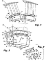
- FIG. 1 a perspective view of an exemplary embodiment of a portion of a vane stage for a gas turbine engine constructed in accordance with the disclosure is shown in Fig. 1 and is designated generally by reference character 100.
- FIGs. 2-4 Other embodiments of vane stages constructed in accordance with the disclosure, or aspects thereof, are provided in Figs. 2-4 , as will be described.
- a vane stage as shown and described herein can be used in a variety of gas turbine engines, for example low bypass ratio gas turbine engines or high bypass ratio gas turbine engines, such as in the second vane stage of a fan section of a low bypass ratio gas turbine engine.
- Embodiments of vanes stages shown and described herein provide improved operation at high temperatures while still having the desired stiffness, and ease of manufacture.
- vane stage 100 includes a plurality of arcuate platforms 102 circumferentially arranged to form an annulus. Each arcuate platform 102 defines a axial centerline axis A. A pair of flanges 104 extend radially inward from each platform 102. Flanges 104 are axially spaced from one another and from respective forward and aft ends 106 and 108, respectively, of platform 102. Vane stage 100 includes vanes 110 extending radially outward from respective platforms 102 and a seal carrier 112 mounted with fasteners 114 to flanges 104 of platforms 102. Seal carrier 112 is mounted axially between flanges 104 so that inner surfaces 105, one of which is shown in Fig.
- a seal 109 extends radially inward from carrier 112 for interfacing with a rotor disk, not shown. It is contemplated that a variety of suitable fasteners 114 can be used, for example, HI-LOK ® pin rivets and shear collars available from Hi-Shear Corporation of Torrance, California.
- vane stage 100 allows for vanes 110 and platforms 102 to be separately formed and then joined together with seal carrier 112. This permits vane 110 and platform 102 to be made from titanium, while seal carrier 112 can be made from a composite material, contrary to traditional configurations where the vanes, platforms and seal carrier are co-fabricated from composite material. High temperatures and pressures tend to be challenging for composite materials, especially for use in components under high aerodynamic loading, such as vanes 110. Vane stage 100 effectively joins titanium vanes and platforms, for example, vanes 110 and platforms 102, to a composite seal carrier, for example, seal carrier 112, providing the durability for high loads and high temperatures but allows use of lightweight composite for the relatively lower stressed seal carrier of the vane stage. Vane 110 and platform 102 are shown as being co-fabricated, however those skilled in the art will readily appreciate that vane 110 and platform 102 can be formed separately from titanium or other suitable materials.
- Vane stage 100 allows vanes 110 and platforms 102 to be joined to seal carrier 112 without the need for adhesives and without the need for bushings adhered to the composite. Adhesives are generally are not capable of operating at high operating temperatures and bushings tend to add weight to the vane stage assembly and tend to increase manufacturing complexity. Additionally, vane stage 100 overcomes traditional problems with using fasteners such as limitations to hole alignment and drilling, and slippage under low flange stack compression and access to fasteners inside the seal carrier.
- an axial distance D between flanges 104 ranges from 63% to 77% of the chord length of one of vanes 110.
- axial distance D between flanges 104 can range from 56% to 84% of the chord length of one of vanes 110, or more particularly, axial distance D can be 70% of the chord length of one of vanes 110.
- One of flanges 104 on each of the platforms 102 proximate to forward end 106 of the platform is axially spaced apart from forward end 106 of the platform the same distance as the other flange 104 proximate to aft end 108 of platform 102 is axially spaced apart from aft end 108 of platform 102.
- the spacing between pairs of flanges 104 relative to the chord length of respective vane 110 provides stiffness for vibration tuning.
- vane stage 100 includes washers 124 mounted to the seal carrier.
- Each washer 124 is opposite of one of flanges 104 of platform 102 across the axial thickness t of one of sides 136 of seal carrier 112.
- a portion 126 of seal carrier 112 between each washer 124 and flange 104 includes two through holes 128 in an axial direction for receiving respective fasteners 114.
- Each washer 124 includes a pair of through holes 130 that correspond to respective pair of holes 132 in flanges 104 and to through holes 128 of seal carrier 112.
- through holes 128 are positioned in seal carrier 112 such that only a few fasteners are required to carry the prying load from differential pressure across seal carrier 112, and the vane over-turning moments caused by aerodynamic gas loads acting on vanes 110 and platforms 102.
- a cross-sectional area of each washer surface that interfaces with seal carrier 112, for example, the surface opposite that of washer surface 134, is at least eight times greater in area than the total cross-sectional area of through holes 128 that the respective washer surface interfaces with, for example, the cross-sectional area of two holes 128.
- the cross-sectional area of each through hole 128 is taken perpendicular to respective hole axes H.
- Each washer 124 assists in spreading out fastener 114 pre-load over respective axial inwardly facing sides 122 of carrier 112.
- washers 124 are shown as having a race-track shape, washers 124 can take any suitable shape, such as, oval, rectangular, egg, round, and/or the like. It is also contemplated that washers 124 can be divided into separate washer portions that make up a similar shape as those described above.
- seal carrier 112 is one of a plurality of arcuate seal carriers.
- Each arcuate seal carrier 112 includes a neck portion 116 at one end that extends in a circumferential direction to nest within an end 118 of a neighboring arcuate seal carrier 112, ultimately forming a seal carrier ring.
- Axial outwardly facing sides 120 of neck portion 116 are interference fit with corresponding axial inwardly facing sides 122 of the neighboring seal carrier 112 in which each neck portion 116 rests.
- the interference fit between respective axial outwardly facing sides 120 of neck portion 116 and axial inwardly facing sides 122 of neighboring carrier 112 provides durability and vibration control for the seal carrier ring.
- method 200 for constructing a vane stage includes sliding a seal carrier, for example, seal carrier 112, between flanges, for example, flanges 104, of an arcuate platform, for example, arcuate platform 102, as shown in box 202.
- Each flange includes at least a pair of through holes, for example, through holes 132, and interfaces with a respective axial side, for example, side 136, of the seal carrier.
- Method 200 includes drilling through holes, for example, through holes 128, in each axial side of the seal carrier by using the through holes, for example, through holes 132, of each flange as guides, for example, transfer drilling, as shown in box 204.
- Method 200 includes securing the axial sides of the seal carrier to respective flanges with fasteners, for example, fasteners 114, inserted through the through holes of the flanges and the seal carrier, as shown in box 206.
- Securing the axial sides of the seal carrier to respective flanges includes placing a washer, for example, washer 124, opposite each flange across the seal carrier, also shown in box 206.
- Each washer includes at least two through holes, for example, through holes 130, for receiving the fasteners. The through holes of each washer correspond to the pair of through holes on each flange.
Landscapes
- Engineering & Computer Science (AREA)
- Mechanical Engineering (AREA)
- General Engineering & Computer Science (AREA)
- Chemical & Material Sciences (AREA)
- Materials Engineering (AREA)
- Turbine Rotor Nozzle Sealing (AREA)
- Structures Of Non-Positive Displacement Pumps (AREA)
Abstract
Description
- The present disclosure relates to turbomachine components, such as stator vane stages and vane support systems in gas turbine engines.
- Traditionally, gas turbine engines can include multiple stages of vanes to condition and guide airflow through the fan, compressor and/or turbine sections. The vane stages are configured to optimize airflow characteristics for various operating conditions. The vane stages are subject to high temperatures, aerodynamic loading and pressures that can affect their durability.
- It is expected that this will be exacerbated due to the ongoing trend of designing gas turbine engines to operate at even higher temperatures and pressures. As such, there is still a need in the art for improved vane stages that can operate at high temperatures while still providing the desired stiffness and ease of manufacture.
- A vane stage includes an arcuate platform defining a axial centerline axis having a pair of flanges that extend radially inward from the platform, The flanges are axially spaced from one another and from respective forward and aft ends of the platform. The vane stage includes a vane extending radially outward from the platform and a seal carrier mounted to the flanges of the platform.
- The axial distance between the flanges can range from 63% to 77% of the chord length of the vane. The axial distance between the flanges can range from 56% to 84% of the chord length of the vane. One of the flanges proximate to the forward end of the platform can be axially spaced apart from the forward end of the platform the same distance as the other flange proximate to the aft end of the platform is axially spaced apart from the aft end of the platform. The seal carrier can be mounted axially between the flanges. The vane and platform can be made from titanium, and/or the seal carrier can be made from composite. The vane and platform can be co-fabricated.
- The seal carrier can be one of a plurality of arcuate seal carriers. Each arcuate seal carrier can include a neck portion at one end that extends in a circumferential direction to nest within an end of a neighboring arcuate seal carrier. Axial outwardly facing sides of each neck portion can be in an interference fit with corresponding axial inwardly facing sides of the neighboring seal carrier in which each neck portion rests.
- In accordance with other embodiments, a vane stage includes a washer mounted to the seal carrier. The washer is opposite of one of the flanges of the platform across the axial thickness of a side of the seal carrier. A portion of the seal carrier between the washer and flange can include at least two through holes in an axial direction for receiving respective fasteners. The washer can include a pair of through holes that correspond to respective pairs of holes in the platform flanges and the seal carrier. A cross-sectional area of the washer surface that interfaces with the seal carrier can be at least eight times greater in area than the total cross-sectional area of through holes in the portion of the seal carrier that the washer surface interfaces with. The washer can have a race-track shape.
- In accordance with another embodiment, a method for constructing a vane stage includes sliding a seal carrier between flanges of an arcuate platform. Each flange includes at least a pair of through holes and interfaces with a respective axial side of the seal carrier. The method includes drilling through holes in each axial side of the seal carrier by using the through holes of each flange as guides. The method can include securing the axial sides of the seal carrier to respective flanges with fasteners inserted through the through holes of the flanges and the seal carrier. Securing the axial sides of the seal carrier to respective flanges can include placing a washer opposite each flange across the seal carrier.
- According to an embodiment, there is provided a vane stage comprising: an arcuate platform defining a axial centerline axis having a pair of flanges that extend radially inward from the platform, wherein the flanges are axially spaced apart from one another and from respective forward and aft ends of the platform; a vane extending radially outward from the platform; and a seal carrier mounted to the flanges of the platform.
- In addition to one or more of the features described above, or as an alternative to any of the foregoing embodiments, an axial distance between the flanges ranges from 63% to 77% of the chord length of the vane.
- In addition to one or more of the features described above, or as an alternative to any of the foregoing embodiments, an axial distance between the flanges ranges from 56% to 84% of the chord length of the vane.
- In addition to one or more of the features described above, or as an alternative to any of the foregoing embodiments, one of the flanges proximate to the forward end of the platform is axially spaced apart from the forward end of the platform the same distance as the other flange proximate to the aft end of the platform is axially spaced apart from the aft end of the platform.
- In addition to one or more of the features described above, or as an alternative to any of the foregoing embodiments, the seal carrier is mounted axially between the flanges.
- In addition to one or more of the features described above, or as an alternative to any of the foregoing embodiments, the vane and platform are titanium.
- In addition to one or more of the features described above, or as an alternative to any of the foregoing embodiments, the seal carrier is composite.
- In addition to one or more of the features described above, or as an alternative to any of the foregoing embodiments, the vane and platform are co-fabricated.
- In addition to one or more of the features described above, or as an alternative to any of the foregoing embodiments, the seal carrier is one of a plurality of arcuate seal carriers, wherein each arcuate seal carrier includes a neck portion at one end that extends in a circumferential direction to nest within an end of a neighboring arcuate seal carrier.
- In addition to one or more of the features described above, or as an alternative to any of the foregoing embodiments, axial outwardly facing sides of each neck portion are in an interference fit with corresponding axial inwardly facing sides of the neighboring seal carrier in which each neck portion rests.
- According to another embodiment there is provided a vane stage comprising: an arcuate vane platform defining a axial centerline axis having a pair of flanges that extend radially inward from the platform; a seal carrier mounted to the flanges of the platform; and a washer mounted to the seal carrier, wherein the washer is opposite of one of the flanges of the platform across an axial thickness of a side of the seal carrier.
- In addition to one or more of the features described above, or as an alternative to any of the foregoing embodiments, a portion of the seal carrier between the washer and flange includes at least two through holes in an axial direction for receiving respective fasteners.
- In addition to one or more of the features described above, or as an alternative to any of the foregoing embodiments, the washer includes a pair of through holes that correspond to respective pairs of holes in the platform flanges and the seal carrier.
- In addition to one or more of the features described above, or as an alternative to any of the foregoing embodiments, a cross-sectional area of the washer surface that interfaces with the seal carrier is at least eight times greater in area than the total cross-sectional area of through holes in the portion of the seal carrier that the washer surface interfaces with.
- In addition to one or more of the features described above, or as an alternative to any of the foregoing embodiments, the washer has a race-track shape.
- According to yet a further embodiment, there is provided a method for constructing a vane stage comprising: sliding a seal carrier between flanges of an arcuate platform, wherein the platform defines a axial centerline axis, wherein the flanges are axially spaced apart from one another and extend radially inward from the platform, wherein each flange includes at least a pair of through holes, and wherein each flange interfaces with a respective axial side of the seal carrier; and drilling through holes in each axial side of the seal carrier by using the through holes of each flange as guides.
- In addition to one or more of the features described above, or as an alternative to any of the foregoing embodiments, securing the axial sides of the seal carrier to respective flanges with fasteners inserted through the through holes of the flanges and the seal carrier.
- In addition to one or more of the features described above, or as an alternative to any of the foregoing embodiments, securing the axial sides of the seal carrier to respective flanges includes placing a washer opposite each flange across the seal carrier, wherein each washer includes at least two through holes for receiving fasteners, wherein the through holes of each washer correspond to the pair of through holes on each flange.
- So that those skilled in the art to which the subject disclosure appertains will readily understand how to make and use the devices and methods of the subject disclosure without undue experimentation, preferred embodiments thereof will be described in detail herein below with reference to certain figures, wherein:
-
Fig. 1 is a perspective exploded view of an exemplary embodiment of a portion of a vane stage constructed in accordance with the present disclosure, showing sides of a seal carrier mounted between a washer and a flange of a vane platform; -
Fig. 2 is a perspective view of a portion of the vane stage ofFig. 1 , showing the fasteners securing the seal carrier, flanges and washers together; -
Fig. 3 is a perspective exploded view of a portion of the vane stage ofFig. 1 , showing the through holes of the washer, seal carrier and flange; and -
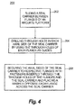
Fig. 4 is a method for constructing a vane stage, schematically showing the method. - Reference will now be made to the drawings wherein like reference numerals identify similar structural features or aspects of the subject disclosure. For purposes of explanation and illustration, and not limitation, a perspective view of an exemplary embodiment of a portion of a vane stage for a gas turbine engine constructed in accordance with the disclosure is shown in
Fig. 1 and is designated generally byreference character 100. Other embodiments of vane stages constructed in accordance with the disclosure, or aspects thereof, are provided inFigs. 2-4 , as will be described. A vane stage as shown and described herein can be used in a variety of gas turbine engines, for example low bypass ratio gas turbine engines or high bypass ratio gas turbine engines, such as in the second vane stage of a fan section of a low bypass ratio gas turbine engine. Embodiments of vanes stages shown and described herein provide improved operation at high temperatures while still having the desired stiffness, and ease of manufacture. - As shown in
Fig. 1 ,vane stage 100 includes a plurality ofarcuate platforms 102 circumferentially arranged to form an annulus. Eacharcuate platform 102 defines a axial centerline axis A. A pair offlanges 104 extend radially inward from eachplatform 102.Flanges 104 are axially spaced from one another and from respective forward and aft ends 106 and 108, respectively, ofplatform 102.Vane stage 100 includesvanes 110 extending radially outward fromrespective platforms 102 and aseal carrier 112 mounted withfasteners 114 toflanges 104 ofplatforms 102.Seal carrier 112 is mounted axially betweenflanges 104 so thatinner surfaces 105, one of which is shown inFig. 3 , offlanges 104, interface withouter surfaces 107 ofseal carrier 112. Aseal 109 extends radially inward fromcarrier 112 for interfacing with a rotor disk, not shown. It is contemplated that a variety ofsuitable fasteners 114 can be used, for example, HI-LOK ® pin rivets and shear collars available from Hi-Shear Corporation of Torrance, California. - With continued reference to
Fig. 1 ,vane stage 100 allows forvanes 110 andplatforms 102 to be separately formed and then joined together withseal carrier 112. This permitsvane 110 andplatform 102 to be made from titanium, whileseal carrier 112 can be made from a composite material, contrary to traditional configurations where the vanes, platforms and seal carrier are co-fabricated from composite material. High temperatures and pressures tend to be challenging for composite materials, especially for use in components under high aerodynamic loading, such asvanes 110.Vane stage 100 effectively joins titanium vanes and platforms, for example,vanes 110 andplatforms 102, to a composite seal carrier, for example,seal carrier 112, providing the durability for high loads and high temperatures but allows use of lightweight composite for the relatively lower stressed seal carrier of the vane stage.Vane 110 andplatform 102 are shown as being co-fabricated, however those skilled in the art will readily appreciate thatvane 110 andplatform 102 can be formed separately from titanium or other suitable materials. -
Vane stage 100 allowsvanes 110 andplatforms 102 to be joined to sealcarrier 112 without the need for adhesives and without the need for bushings adhered to the composite. Adhesives are generally are not capable of operating at high operating temperatures and bushings tend to add weight to the vane stage assembly and tend to increase manufacturing complexity. Additionally,vane stage 100 overcomes traditional problems with using fasteners such as limitations to hole alignment and drilling, and slippage under low flange stack compression and access to fasteners inside the seal carrier. - As shown in
Fig. 2 , an axial distance D betweenflanges 104 ranges from 63% to 77% of the chord length of one ofvanes 110. For example, axial distance D betweenflanges 104 can range from 56% to 84% of the chord length of one ofvanes 110, or more particularly, axial distance D can be 70% of the chord length of one ofvanes 110. One offlanges 104 on each of theplatforms 102 proximate toforward end 106 of the platform is axially spaced apart fromforward end 106 of the platform the same distance as theother flange 104 proximate toaft end 108 ofplatform 102 is axially spaced apart fromaft end 108 ofplatform 102. The spacing between pairs offlanges 104 relative to the chord length ofrespective vane 110 provides stiffness for vibration tuning. - With reference now to
Figs. 2 and 3 ,vane stage 100 includeswashers 124 mounted to the seal carrier. Eachwasher 124 is opposite of one offlanges 104 ofplatform 102 across the axial thickness t of one ofsides 136 ofseal carrier 112. Aportion 126 ofseal carrier 112 between eachwasher 124 andflange 104 includes two throughholes 128 in an axial direction for receivingrespective fasteners 114. Eachwasher 124 includes a pair of throughholes 130 that correspond to respective pair ofholes 132 inflanges 104 and to throughholes 128 ofseal carrier 112. Those skilled in the art will readily appreciate that throughholes 128 are positioned inseal carrier 112 such that only a few fasteners are required to carry the prying load from differential pressure acrossseal carrier 112, and the vane over-turning moments caused by aerodynamic gas loads acting onvanes 110 andplatforms 102. - With continued reference to
Fig. 3 , a cross-sectional area of each washer surface that interfaces withseal carrier 112, for example, the surface opposite that ofwasher surface 134, is at least eight times greater in area than the total cross-sectional area of throughholes 128 that the respective washer surface interfaces with, for example, the cross-sectional area of twoholes 128. The cross-sectional area of each throughhole 128 is taken perpendicular to respective hole axes H. Eachwasher 124 assists in spreading outfastener 114 pre-load over respective axial inwardly facingsides 122 ofcarrier 112. Those skilled in the art will readily appreciate that whilewashers 124 are shown as having a race-track shape,washers 124 can take any suitable shape, such as, oval, rectangular, egg, round, and/or the like. It is also contemplated thatwashers 124 can be divided into separate washer portions that make up a similar shape as those described above. - As shown in
Figs. 1 and 2 ,seal carrier 112 is one of a plurality of arcuate seal carriers. Eacharcuate seal carrier 112 includes aneck portion 116 at one end that extends in a circumferential direction to nest within anend 118 of a neighboringarcuate seal carrier 112, ultimately forming a seal carrier ring. Axial outwardly facingsides 120 ofneck portion 116 are interference fit with corresponding axial inwardly facingsides 122 of the neighboringseal carrier 112 in which eachneck portion 116 rests. The interference fit between respective axial outwardly facingsides 120 ofneck portion 116 and axial inwardly facingsides 122 of neighboringcarrier 112 provides durability and vibration control for the seal carrier ring. - With reference now to
Fig. 4 ,method 200 for constructing a vane stage, for example,vane stage 100, includes sliding a seal carrier, for example,seal carrier 112, between flanges, for example,flanges 104, of an arcuate platform, for example,arcuate platform 102, as shown inbox 202. Each flange includes at least a pair of through holes, for example, throughholes 132, and interfaces with a respective axial side, for example,side 136, of the seal carrier.Method 200 includes drilling through holes, for example, throughholes 128, in each axial side of the seal carrier by using the through holes, for example, throughholes 132, of each flange as guides, for example, transfer drilling, as shown inbox 204. By assembling the vane stage with the flanges placed on outer surfaces, for example,outer surfaces 107, of the seal carrier and using the through holes of each flange as guides, the need for bushings and adhesive is eliminated, reducing weight and manufacturing complexity. -
Method 200 includes securing the axial sides of the seal carrier to respective flanges with fasteners, for example,fasteners 114, inserted through the through holes of the flanges and the seal carrier, as shown inbox 206. Securing the axial sides of the seal carrier to respective flanges includes placing a washer, for example,washer 124, opposite each flange across the seal carrier, also shown inbox 206. Each washer includes at least two through holes, for example, throughholes 130, for receiving the fasteners. The through holes of each washer correspond to the pair of through holes on each flange. - The methods and systems of the present disclosure, as described above and shown in the drawings, provide for gas turbine engines and vane stages with superior properties including reduced weight and increased stiffness. While the apparatus and methods of the subject disclosure have been shown and described with reference to preferred embodiments, those skilled in the art will readily appreciate that changes and/or modifications may be made thereto without departing from the scope of the subject disclosure.
- The following clauses set out features of the present disclosure which may or may not presently be claimed but which may form basis for future amendments and/or a divisional application.
- 1. A vane stage comprising:
- an arcuate platform defining a axial centerline axis having a pair of flanges that extend radially inward from the platform, wherein the flanges are axially spaced apart from one another and from respective forward and aft ends of the platform;
- a vane extending radially outward from the platform; and
- a seal carrier mounted to the flanges of the platform.
- 2. A vane stage as recited in clause 1, wherein an axial distance between the flanges ranges from 63% to 77% of the chord length of the vane.
- 3. A vane stage as recited in clause 1, wherein an axial distance between the flanges ranges from 56% to 84% of the chord length of the vane.
- 4. A vane stage as recited in clause 1, wherein one of the flanges proximate to the forward end of the platform is axially spaced apart from the forward end of the platform the same distance as the other flange proximate to the aft end of the platform is axially spaced apart from the aft end of the platform.
- 5. A vane stage as recited in clause 1, wherein the seal carrier is mounted axially between the flanges.
- 6. A vane stage as recited in clause 1, wherein the vane and platform are titanium.
- 7. A vane stage tem as recited in clause 1, wherein the seal carrier is composite.
- 8. A vane stage as recited in clause 1, wherein the vane and platform are co-fabricated.
- 9. A vane stage as recited in clause 1, wherein the seal carrier is one of a plurality of arcuate seal carriers, wherein each arcuate seal carrier includes a neck portion at one end that extends in a circumferential direction to nest within an end of a neighboring arcuate seal carrier.
- 10. A vane stage as recited in clause 9, wherein axial outwardly facing sides of each neck portion are in an interference fit with corresponding axial inwardly facing sides of the neighboring seal carrier in which each neck portion rests.
- 11. A vane stage comprising:
- an arcuate vane platform defining a axial centerline axis having a pair of flanges that extend radially inward from the platform;
- a seal carrier mounted to the flanges of the platform; and
- a washer mounted to the seal carrier, wherein the washer is opposite of one of the flanges of the platform across an axial thickness of a side of the seal carrier.
- 12. A vane stage as recited in clause 11, wherein a portion of the seal carrier between the washer and flange includes at least two through holes in an axial direction for receiving respective fasteners.
- 13. A vane stage as recited in clause 11, wherein the washer includes a pair of through holes that correspond to respective pairs of holes in the platform flanges and the seal carrier.
- 14. A vane stage as recited in clause 11, wherein a cross-sectional area of the washer surface that interfaces with the seal carrier is at least eight times greater in area than the total cross-sectional area of through holes in the portion of the seal carrier that the washer surface interfaces with.
- 15. A vane stage as recited in clause 11, wherein the washer has a race-track shape.
- 16. A method for constructing a vane stage comprising:
- sliding a seal carrier between flanges of an arcuate platform, wherein the platform defines a axial centerline axis, wherein the flanges are axially spaced apart from one another and extend radially inward from the platform, wherein each flange includes at least a pair of through holes, and wherein each flange interfaces with a respective axial side of the seal carrier; and
- drilling through holes in each axial side of the seal carrier by using the through holes of each flange as guides.
- 17. A method as recited in clause 16, further comprising securing the axial sides of the seal carrier to respective flanges with fasteners inserted through the through holes of the flanges and the seal carrier.
- 18. A method as recited in clause 17, wherein securing the axial sides of the seal carrier to respective flanges includes placing a washer opposite each flange across the seal carrier, wherein each washer includes at least two through holes for receiving fasteners, wherein the through holes of each washer correspond to the pair of through holes on each flange.
Claims (15)
- A vane stage (100) comprising:an arcuate platform (102) defining an axial centerline axis having a pair of flanges (104) that extend radially inward from the platform, wherein the flanges are axially spaced apart from one another and from respective forward (106) and aft (108) ends of the platform;a vane (110) extending radially outward from the platform; anda seal carrier (112) mounted to the flanges of the platform.
- A vane stage (100) as recited in claim 1, wherein an axial distance between the flanges (104) ranges from 63% to 77% of the chord length of the vane (110).
- A vane stage (100) as recited in claim 1, wherein an axial distance between the flanges (104) ranges from 56% to 84% of the chord length of the vane (110).
- A vane stage (100) as recited in claim 1, 2 or 3, wherein one of the flanges (104) proximate to the forward end (106) of the platform (102) is axially spaced apart from the forward end of the platform the same distance as the other flange proximate to the aft end (108) of the platform is axially spaced apart from the aft end of the platform.
- A vane stage (100) as recited in any preceding claim, wherein the seal carrier (112) is mounted axially between the flanges (104).
- A vane stage (100) as recited in any preceding claim, wherein the vane (110) and platform (102) are titanium, and/or wherein the seal carrier (112) is composite.
- A vane stage (100) as recited in any preceding claim, wherein the vane (110) and platform (102) are co-fabricated.
- A vane stage as recited in any preceding claim, wherein the seal carrier (112) is one of a plurality of arcuate seal carriers, wherein each arcuate seal carrier includes a neck portion (116) at one end that extends in a circumferential direction to nest within an end of a neighboring arcuate seal carrier, and preferably wherein axial outwardly facing sides (120) of each neck portion are in an interference fit with corresponding axial inwardly facing sides (122) of the neighboring seal carrier in which each neck portion rests.
- A vane stage as recited in any preceding claim, wherein the vane stage further comprises a washer (124) mounted to the seal carrier (112), wherein the washer is opposite of one of the flanges (104) of the platform across an axial thickness of a side (136) of the seal carrier.
- A vane stage (100) comprising:an arcuate vane platform defining an axial centerline axis having a pair of flanges that extend radially inward from the platform (102);a seal carrier mounted to the flanges of the platform; anda washer (124) mounted to the seal carrier (112), wherein the washer is opposite of one of the flanges (104) of the platform across an axial thickness of a side (136) of the seal carrier.
- A vane stage (100) as recited in claim 9 or 10, wherein a portion (126) of the seal carrier (112) between the washer (124) and flange (104) includes at least two through holes (128) in an axial direction for receiving respective fasteners (114).
- A vane stage (100) as recited in any one of claims 9, 10 or 11, wherein the washer (124) includes a pair of through holes (130) that correspond to respective pairs of holes (132, 128) in the platform flanges (104) and the seal carrier (112).
- A vane stage (100) as recited in any one of claims 9 to 12, wherein a cross-sectional area of the washer surface (134) that interfaces with the seal carrier (112) is at least eight times greater in area than the total cross-sectional area of through holes (128) in the portion of the seal carrier that the washer surface interfaces with, and/or wherein the washer (124) has a race-track shape.
- A method for constructing a vane stage (100) comprising:sliding a seal carrier (112) between flanges (104) of an arcuate platform (102), wherein the platform defines an axial centerline axis, wherein the flanges (104) are axially spaced apart from one another and extend radially inward from the platform, wherein each flange includes at least a pair of through holes (132), and wherein each flange interfaces with a respective axial side of the seal carrier (112); anddrilling through holes (128) in each axial side of the seal carrier by using the through holes of each flange as guides.
- A method as recited in claim 14, further comprising securing the axial sides of the seal carrier (112) to respective flanges (104) with fasteners (114) inserted through the through holes (132, 128) of the flanges (104) and the seal carrier, wherein securing the axial sides of the seal carrier to respective flanges (104) includes placing a washer (124) opposite each flange across the seal carrier, wherein each washer includes at least two through holes (130) for receiving fasteners (114), and preferably wherein the through holes of each washer correspond to the pair of through holes (132) on each flange.
Applications Claiming Priority (1)
| Application Number | Priority Date | Filing Date | Title |
|---|---|---|---|
| US14/616,274 US10202857B2 (en) | 2015-02-06 | 2015-02-06 | Vane stages |
Publications (3)
| Publication Number | Publication Date |
|---|---|
| EP3054104A2 true EP3054104A2 (en) | 2016-08-10 |
| EP3054104A3 EP3054104A3 (en) | 2016-12-21 |
| EP3054104B1 EP3054104B1 (en) | 2020-04-15 |
Family
ID=55310741
Family Applications (1)
| Application Number | Title | Priority Date | Filing Date |
|---|---|---|---|
| EP16154554.6A Active EP3054104B1 (en) | 2015-02-06 | 2016-02-05 | Vane stages |
Country Status (2)
| Country | Link |
|---|---|
| US (2) | US10202857B2 (en) |
| EP (1) | EP3054104B1 (en) |
Cited By (2)
| Publication number | Priority date | Publication date | Assignee | Title |
|---|---|---|---|---|
| EP3597861A1 (en) * | 2018-07-19 | 2020-01-22 | United Technologies Corporation | Contact coupled airfoil singlets |
| WO2021009157A1 (en) * | 2019-07-16 | 2021-01-21 | Gkn Aerospace Sweden Ab | Injection bonding of composite vane into pocket |
Families Citing this family (8)
| Publication number | Priority date | Publication date | Assignee | Title |
|---|---|---|---|---|
| US10202857B2 (en) | 2015-02-06 | 2019-02-12 | United Technologies Corporation | Vane stages |
| FR3046951B1 (en) * | 2016-01-21 | 2018-01-12 | Safran Aircraft Engines | PROCESS FOR MANUFACTURING A PIECE OF A TURBOMACHINE AND PIECE PRODUCED THEREBY |
| FR3064023B1 (en) * | 2017-03-16 | 2019-09-13 | Safran Aircraft Engines | TURBINE RING ASSEMBLY |
| US10822975B2 (en) * | 2018-06-27 | 2020-11-03 | Raytheon Technologies Corporation | Vane system with connectors of different length |
| US11765864B2 (en) | 2019-08-26 | 2023-09-19 | Ovh | Cooling arrangement for a rack hosting electronic equipment and at least one fan |
| US11629606B2 (en) * | 2021-05-26 | 2023-04-18 | General Electric Company | Split-line stator vane assembly |
| US11781432B2 (en) | 2021-07-26 | 2023-10-10 | Rtx Corporation | Nested vane arrangement for gas turbine engine |
| US11773735B2 (en) | 2021-12-22 | 2023-10-03 | Rolls-Royce Plc | Vane ring assembly with ceramic matrix composite airfoils |
Family Cites Families (46)
| Publication number | Priority date | Publication date | Assignee | Title |
|---|---|---|---|---|
| US160862A (en) * | 1875-03-16 | Improvement in nut-locks | ||
| GB701101A (en) | 1950-06-29 | 1953-12-16 | Rolls Royce | Improvements in or relating to gas-turbine engines |
| US2868439A (en) * | 1954-05-07 | 1959-01-13 | Goodyear Aircraft Corp | Plastic axial-flow compressor for gas turbines |
| US2915280A (en) | 1957-04-18 | 1959-12-01 | Gen Electric | Nozzle and seal assembly |
| US3275294A (en) * | 1963-11-14 | 1966-09-27 | Westinghouse Electric Corp | Elastic fluid apparatus |
| US3411794A (en) * | 1966-12-12 | 1968-11-19 | Gen Motors Corp | Cooled seal ring |
| US3727660A (en) * | 1971-02-16 | 1973-04-17 | Gen Electric | Bolt retainer and compressor employing same |
| US3945758A (en) | 1974-02-28 | 1976-03-23 | Westinghouse Electric Corporation | Cooling system for a gas turbine |
| US3941500A (en) * | 1974-06-10 | 1976-03-02 | Westinghouse Electric Corporation | Turbomachine interstage seal assembly |
| US4113406A (en) | 1976-11-17 | 1978-09-12 | Westinghouse Electric Corp. | Cooling system for a gas turbine engine |
| US4380413A (en) * | 1980-11-03 | 1983-04-19 | Illinois Tool Works Inc. | Load-distributive washer for use with compressible material |
| GB2110768A (en) | 1981-12-01 | 1983-06-22 | Rolls Royce | Fixings for stator vanes |
| US4897021A (en) * | 1988-06-02 | 1990-01-30 | United Technologies Corporation | Stator vane asssembly for an axial flow rotary machine |
| US4869640A (en) | 1988-09-16 | 1989-09-26 | United Technologies Corporation | Controlled temperature rotating seal |
| JP3631271B2 (en) * | 1993-11-19 | 2005-03-23 | ユナイテッド テクノロジーズ コーポレイション | Inner shroud integrated stator vane structure |
| US5599131A (en) * | 1994-05-23 | 1997-02-04 | Flexible Steel Lacing Company | Plate fastener with bolts preassembled |
| DE19507673C2 (en) * | 1995-03-06 | 1997-07-03 | Mtu Muenchen Gmbh | Guide wheel for turbomachinery |
| EP0945597A1 (en) | 1998-03-23 | 1999-09-29 | Asea Brown Boveri AG | Stator vane assembly for a gas turbine plant |
| US6220815B1 (en) * | 1999-12-17 | 2001-04-24 | General Electric Company | Inter-stage seal retainer and assembly |
| US6425738B1 (en) * | 2000-05-11 | 2002-07-30 | General Electric Company | Accordion nozzle |
| US20110150640A1 (en) | 2003-08-21 | 2011-06-23 | Peter Tiemann | Labyrinth Seal in a Stationary Gas Turbine |
| JP4412081B2 (en) | 2004-07-07 | 2010-02-10 | 株式会社日立製作所 | Gas turbine and gas turbine cooling method |
| GB2426301B (en) * | 2005-05-19 | 2007-07-18 | Rolls Royce Plc | A seal arrangement |
| US7494317B2 (en) * | 2005-06-23 | 2009-02-24 | Siemens Energy, Inc. | Ring seal attachment system |
| FR2889249B1 (en) * | 2005-07-29 | 2007-10-19 | Snecma | MOUNTING A LABYRINTH SEAL SUPPORT ON A TURBOMACHINE ROTOR |
| AT503840B1 (en) * | 2006-06-30 | 2010-09-15 | Facc Ag | ROD ROD ARRANGEMENT FOR A TRANSMISSION |
| US7722317B2 (en) * | 2007-01-25 | 2010-05-25 | Siemens Energy, Inc. | CMC to metal attachment mechanism |
| WO2008118344A1 (en) * | 2007-03-27 | 2008-10-02 | Matthew Robert Younce | Universal two-hole electrical bond washer |
| FR2920492B1 (en) * | 2007-08-30 | 2009-10-30 | Snecma Sa | VARIABLE SHAFT OF AUBES FOR A TURBOMACHINE |
| US8292580B2 (en) * | 2008-09-18 | 2012-10-23 | Siemens Energy, Inc. | CMC vane assembly apparatus and method |
| US8454303B2 (en) * | 2010-01-14 | 2013-06-04 | General Electric Company | Turbine nozzle assembly |
| FR2956876B1 (en) * | 2010-02-26 | 2012-10-19 | Snecma | STRUCTURAL AND AERODYNAMIC MODULE OF A TURBOMACHINE CASING AND CARTER STRUCTURE COMPRISING A PLURALITY OF SUCH A MODULE |
| GB201111666D0 (en) * | 2011-07-08 | 2011-08-24 | Rolls Royce Plc | A joint assembly for an annular structure |
| FR2979662B1 (en) | 2011-09-07 | 2013-09-27 | Snecma | PROCESS FOR MANUFACTURING TURBINE DISPENSER SECTOR OR COMPRESSOR RECTIFIER OF COMPOSITE MATERIAL FOR TURBOMACHINE AND TURBINE OR COMPRESSOR INCORPORATING A DISPENSER OR RECTIFIER FORMED OF SUCH SECTORS |
| JP6012222B2 (en) * | 2012-03-30 | 2016-10-25 | 三菱重工業株式会社 | Stator blade segment, axial fluid machine including the same, and stator vane coupling method thereof |
| EP2666969B1 (en) * | 2012-05-21 | 2017-04-19 | General Electric Technology GmbH | Turbine diaphragm construction |
| US20140004293A1 (en) | 2012-06-30 | 2014-01-02 | General Electric Company | Ceramic matrix composite component and a method of attaching a static seal to a ceramic matrix composite component |
| EP2984292B1 (en) * | 2013-04-12 | 2018-06-06 | United Technologies Corporation | Stator vane platform with flanges |
| DE102013219024A1 (en) * | 2013-09-23 | 2015-04-09 | MTU Aero Engines AG | Component system of a turbomachine |
| US9702395B2 (en) * | 2014-07-23 | 2017-07-11 | Harger, Inc. | Bonding lug washer |
| US10036263B2 (en) * | 2014-10-22 | 2018-07-31 | United Technologies Corporation | Stator assembly with pad interface for a gas turbine engine |
| US9587517B2 (en) * | 2014-12-29 | 2017-03-07 | Rolls-Royce North American Technologies, Inc. | Blade track assembly with turbine tip clearance control |
| US10202857B2 (en) | 2015-02-06 | 2019-02-12 | United Technologies Corporation | Vane stages |
| US9863265B2 (en) * | 2015-04-15 | 2018-01-09 | General Electric Company | Shroud assembly and shroud for gas turbine engine |
| US10294808B2 (en) * | 2016-04-21 | 2019-05-21 | United Technologies Corporation | Fastener retention mechanism |
| US10494936B2 (en) * | 2016-05-23 | 2019-12-03 | United Technologies Corporation | Fastener retention mechanism |
-
2015
- 2015-02-06 US US14/616,274 patent/US10202857B2/en active Active
-
2016
- 2016-02-05 EP EP16154554.6A patent/EP3054104B1/en active Active
-
2019
- 2019-02-11 US US16/272,175 patent/US11408296B2/en active Active
Non-Patent Citations (1)
| Title |
|---|
| None |
Cited By (4)
| Publication number | Priority date | Publication date | Assignee | Title |
|---|---|---|---|---|
| EP3597861A1 (en) * | 2018-07-19 | 2020-01-22 | United Technologies Corporation | Contact coupled airfoil singlets |
| US10738634B2 (en) | 2018-07-19 | 2020-08-11 | Raytheon Technologies Corporation | Contact coupled singlets |
| WO2021009157A1 (en) * | 2019-07-16 | 2021-01-21 | Gkn Aerospace Sweden Ab | Injection bonding of composite vane into pocket |
| US12472699B2 (en) | 2019-07-16 | 2025-11-18 | Gkn Aerospace Sweden Ab | Injection bonding of composite vane into pocket |
Also Published As
| Publication number | Publication date |
|---|---|
| US11408296B2 (en) | 2022-08-09 |
| US20200024992A1 (en) | 2020-01-23 |
| US20160230574A1 (en) | 2016-08-11 |
| US10202857B2 (en) | 2019-02-12 |
| EP3054104B1 (en) | 2020-04-15 |
| EP3054104A3 (en) | 2016-12-21 |
Similar Documents
| Publication | Publication Date | Title |
|---|---|---|
| US11408296B2 (en) | Vane stages | |
| EP2995777B1 (en) | Vane ring for a gas turbine engine | |
| US9303521B2 (en) | Interstage coverplate assembly for arranging between adjacent rotor stages of a rotor assembly | |
| WO2006110125A3 (en) | Stacked annular components for turbine engines | |
| US10161251B2 (en) | Turbomachine rotors with thermal regulation | |
| US20190368360A1 (en) | Turbine vane assembly with ceramic matrix composite components | |
| US10273820B2 (en) | Turbine vane cooling arrangement | |
| US10662814B2 (en) | Stator shroud systems | |
| EP3246517B1 (en) | Fastener openings for stress distribution | |
| EP2971615B1 (en) | Low leakage duct segment using expansion joint assembly | |
| US9366185B2 (en) | Flexible connection between a wall and a case of a turbine engine | |
| EP3009604B1 (en) | Radially fastened fixed-variable vane system | |
| US10316749B2 (en) | Conduit for guiding low pressure compressor inner diameter shroud motion | |
| EP3358154A1 (en) | Case flange with stress reducing features | |
| EP3656989B1 (en) | Flange stress-reduction features | |
| US9593586B2 (en) | Vane assembly and method of making the same | |
| EP3663543B1 (en) | Case flange with scallop features | |
| EP3135892B1 (en) | Exhaust mixer with outer lobe constraint band | |
| EP2955360B1 (en) | Duct | |
| US20180149169A1 (en) | Support structure for radial inlet of gas turbine engine |
Legal Events
| Date | Code | Title | Description |
|---|---|---|---|
| PUAI | Public reference made under article 153(3) epc to a published international application that has entered the european phase |
Free format text: ORIGINAL CODE: 0009012 |
|
| AK | Designated contracting states |
Kind code of ref document: A2 Designated state(s): AL AT BE BG CH CY CZ DE DK EE ES FI FR GB GR HR HU IE IS IT LI LT LU LV MC MK MT NL NO PL PT RO RS SE SI SK SM TR |
|
| AX | Request for extension of the european patent |
Extension state: BA ME |
|
| RAP1 | Party data changed (applicant data changed or rights of an application transferred) |
Owner name: UNITED TECHNOLOGIES CORPORATION |
|
| PUAL | Search report despatched |
Free format text: ORIGINAL CODE: 0009013 |
|
| AK | Designated contracting states |
Kind code of ref document: A3 Designated state(s): AL AT BE BG CH CY CZ DE DK EE ES FI FR GB GR HR HU IE IS IT LI LT LU LV MC MK MT NL NO PL PT RO RS SE SI SK SM TR |
|
| AX | Request for extension of the european patent |
Extension state: BA ME |
|
| RIC1 | Information provided on ipc code assigned before grant |
Ipc: F01D 25/24 20060101ALI20161114BHEP Ipc: F01D 11/00 20060101AFI20161114BHEP |
|
| STAA | Information on the status of an ep patent application or granted ep patent |
Free format text: STATUS: REQUEST FOR EXAMINATION WAS MADE |
|
| 17P | Request for examination filed |
Effective date: 20170621 |
|
| RBV | Designated contracting states (corrected) |
Designated state(s): AL AT BE BG CH CY CZ DE DK EE ES FI FR GB GR HR HU IE IS IT LI LT LU LV MC MK MT NL NO PL PT RO RS SE SI SK SM TR |
|
| STAA | Information on the status of an ep patent application or granted ep patent |
Free format text: STATUS: EXAMINATION IS IN PROGRESS |
|
| 17Q | First examination report despatched |
Effective date: 20180614 |
|
| GRAP | Despatch of communication of intention to grant a patent |
Free format text: ORIGINAL CODE: EPIDOSNIGR1 |
|
| STAA | Information on the status of an ep patent application or granted ep patent |
Free format text: STATUS: GRANT OF PATENT IS INTENDED |
|
| INTG | Intention to grant announced |
Effective date: 20191105 |
|
| GRAS | Grant fee paid |
Free format text: ORIGINAL CODE: EPIDOSNIGR3 |
|
| GRAA | (expected) grant |
Free format text: ORIGINAL CODE: 0009210 |
|
| STAA | Information on the status of an ep patent application or granted ep patent |
Free format text: STATUS: THE PATENT HAS BEEN GRANTED |
|
| AK | Designated contracting states |
Kind code of ref document: B1 Designated state(s): AL AT BE BG CH CY CZ DE DK EE ES FI FR GB GR HR HU IE IS IT LI LT LU LV MC MK MT NL NO PL PT RO RS SE SI SK SM TR |
|
| REG | Reference to a national code |
Ref country code: CH Ref legal event code: EP |
|
| REG | Reference to a national code |
Ref country code: DE Ref legal event code: R096 Ref document number: 602016033907 Country of ref document: DE |
|
| REG | Reference to a national code |
Ref country code: IE Ref legal event code: FG4D |
|
| REG | Reference to a national code |
Ref country code: AT Ref legal event code: REF Ref document number: 1257523 Country of ref document: AT Kind code of ref document: T Effective date: 20200515 |
|
| REG | Reference to a national code |
Ref country code: NL Ref legal event code: MP Effective date: 20200415 |
|
| REG | Reference to a national code |
Ref country code: LT Ref legal event code: MG4D |
|
| PG25 | Lapsed in a contracting state [announced via postgrant information from national office to epo] |
Ref country code: SE Free format text: LAPSE BECAUSE OF FAILURE TO SUBMIT A TRANSLATION OF THE DESCRIPTION OR TO PAY THE FEE WITHIN THE PRESCRIBED TIME-LIMIT Effective date: 20200415 Ref country code: NO Free format text: LAPSE BECAUSE OF FAILURE TO SUBMIT A TRANSLATION OF THE DESCRIPTION OR TO PAY THE FEE WITHIN THE PRESCRIBED TIME-LIMIT Effective date: 20200715 Ref country code: IS Free format text: LAPSE BECAUSE OF FAILURE TO SUBMIT A TRANSLATION OF THE DESCRIPTION OR TO PAY THE FEE WITHIN THE PRESCRIBED TIME-LIMIT Effective date: 20200815 Ref country code: GR Free format text: LAPSE BECAUSE OF FAILURE TO SUBMIT A TRANSLATION OF THE DESCRIPTION OR TO PAY THE FEE WITHIN THE PRESCRIBED TIME-LIMIT Effective date: 20200716 Ref country code: FI Free format text: LAPSE BECAUSE OF FAILURE TO SUBMIT A TRANSLATION OF THE DESCRIPTION OR TO PAY THE FEE WITHIN THE PRESCRIBED TIME-LIMIT Effective date: 20200415 Ref country code: PT Free format text: LAPSE BECAUSE OF FAILURE TO SUBMIT A TRANSLATION OF THE DESCRIPTION OR TO PAY THE FEE WITHIN THE PRESCRIBED TIME-LIMIT Effective date: 20200817 Ref country code: NL Free format text: LAPSE BECAUSE OF FAILURE TO SUBMIT A TRANSLATION OF THE DESCRIPTION OR TO PAY THE FEE WITHIN THE PRESCRIBED TIME-LIMIT Effective date: 20200415 Ref country code: LT Free format text: LAPSE BECAUSE OF FAILURE TO SUBMIT A TRANSLATION OF THE DESCRIPTION OR TO PAY THE FEE WITHIN THE PRESCRIBED TIME-LIMIT Effective date: 20200415 |
|
| REG | Reference to a national code |
Ref country code: AT Ref legal event code: MK05 Ref document number: 1257523 Country of ref document: AT Kind code of ref document: T Effective date: 20200415 |
|
| PG25 | Lapsed in a contracting state [announced via postgrant information from national office to epo] |
Ref country code: LV Free format text: LAPSE BECAUSE OF FAILURE TO SUBMIT A TRANSLATION OF THE DESCRIPTION OR TO PAY THE FEE WITHIN THE PRESCRIBED TIME-LIMIT Effective date: 20200415 Ref country code: RS Free format text: LAPSE BECAUSE OF FAILURE TO SUBMIT A TRANSLATION OF THE DESCRIPTION OR TO PAY THE FEE WITHIN THE PRESCRIBED TIME-LIMIT Effective date: 20200415 Ref country code: HR Free format text: LAPSE BECAUSE OF FAILURE TO SUBMIT A TRANSLATION OF THE DESCRIPTION OR TO PAY THE FEE WITHIN THE PRESCRIBED TIME-LIMIT Effective date: 20200415 Ref country code: BG Free format text: LAPSE BECAUSE OF FAILURE TO SUBMIT A TRANSLATION OF THE DESCRIPTION OR TO PAY THE FEE WITHIN THE PRESCRIBED TIME-LIMIT Effective date: 20200715 |
|
| PG25 | Lapsed in a contracting state [announced via postgrant information from national office to epo] |
Ref country code: AL Free format text: LAPSE BECAUSE OF FAILURE TO SUBMIT A TRANSLATION OF THE DESCRIPTION OR TO PAY THE FEE WITHIN THE PRESCRIBED TIME-LIMIT Effective date: 20200415 |
|
| REG | Reference to a national code |
Ref country code: DE Ref legal event code: R097 Ref document number: 602016033907 Country of ref document: DE |
|
| PG25 | Lapsed in a contracting state [announced via postgrant information from national office to epo] |
Ref country code: DK Free format text: LAPSE BECAUSE OF FAILURE TO SUBMIT A TRANSLATION OF THE DESCRIPTION OR TO PAY THE FEE WITHIN THE PRESCRIBED TIME-LIMIT Effective date: 20200415 Ref country code: AT Free format text: LAPSE BECAUSE OF FAILURE TO SUBMIT A TRANSLATION OF THE DESCRIPTION OR TO PAY THE FEE WITHIN THE PRESCRIBED TIME-LIMIT Effective date: 20200415 Ref country code: CZ Free format text: LAPSE BECAUSE OF FAILURE TO SUBMIT A TRANSLATION OF THE DESCRIPTION OR TO PAY THE FEE WITHIN THE PRESCRIBED TIME-LIMIT Effective date: 20200415 Ref country code: ES Free format text: LAPSE BECAUSE OF FAILURE TO SUBMIT A TRANSLATION OF THE DESCRIPTION OR TO PAY THE FEE WITHIN THE PRESCRIBED TIME-LIMIT Effective date: 20200415 Ref country code: EE Free format text: LAPSE BECAUSE OF FAILURE TO SUBMIT A TRANSLATION OF THE DESCRIPTION OR TO PAY THE FEE WITHIN THE PRESCRIBED TIME-LIMIT Effective date: 20200415 Ref country code: IT Free format text: LAPSE BECAUSE OF FAILURE TO SUBMIT A TRANSLATION OF THE DESCRIPTION OR TO PAY THE FEE WITHIN THE PRESCRIBED TIME-LIMIT Effective date: 20200415 Ref country code: SM Free format text: LAPSE BECAUSE OF FAILURE TO SUBMIT A TRANSLATION OF THE DESCRIPTION OR TO PAY THE FEE WITHIN THE PRESCRIBED TIME-LIMIT Effective date: 20200415 Ref country code: RO Free format text: LAPSE BECAUSE OF FAILURE TO SUBMIT A TRANSLATION OF THE DESCRIPTION OR TO PAY THE FEE WITHIN THE PRESCRIBED TIME-LIMIT Effective date: 20200415 |
|
| PLBE | No opposition filed within time limit |
Free format text: ORIGINAL CODE: 0009261 |
|
| STAA | Information on the status of an ep patent application or granted ep patent |
Free format text: STATUS: NO OPPOSITION FILED WITHIN TIME LIMIT |
|
| PG25 | Lapsed in a contracting state [announced via postgrant information from national office to epo] |
Ref country code: PL Free format text: LAPSE BECAUSE OF FAILURE TO SUBMIT A TRANSLATION OF THE DESCRIPTION OR TO PAY THE FEE WITHIN THE PRESCRIBED TIME-LIMIT Effective date: 20200415 Ref country code: SK Free format text: LAPSE BECAUSE OF FAILURE TO SUBMIT A TRANSLATION OF THE DESCRIPTION OR TO PAY THE FEE WITHIN THE PRESCRIBED TIME-LIMIT Effective date: 20200415 |
|
| 26N | No opposition filed |
Effective date: 20210118 |
|
| PG25 | Lapsed in a contracting state [announced via postgrant information from national office to epo] |
Ref country code: SI Free format text: LAPSE BECAUSE OF FAILURE TO SUBMIT A TRANSLATION OF THE DESCRIPTION OR TO PAY THE FEE WITHIN THE PRESCRIBED TIME-LIMIT Effective date: 20200415 |
|
| PG25 | Lapsed in a contracting state [announced via postgrant information from national office to epo] |
Ref country code: MC Free format text: LAPSE BECAUSE OF FAILURE TO SUBMIT A TRANSLATION OF THE DESCRIPTION OR TO PAY THE FEE WITHIN THE PRESCRIBED TIME-LIMIT Effective date: 20200415 |
|
| REG | Reference to a national code |
Ref country code: BE Ref legal event code: MM Effective date: 20210228 |
|
| PG25 | Lapsed in a contracting state [announced via postgrant information from national office to epo] |
Ref country code: LU Free format text: LAPSE BECAUSE OF NON-PAYMENT OF DUE FEES Effective date: 20210205 Ref country code: LI Free format text: LAPSE BECAUSE OF NON-PAYMENT OF DUE FEES Effective date: 20210228 Ref country code: CH Free format text: LAPSE BECAUSE OF NON-PAYMENT OF DUE FEES Effective date: 20210228 |
|
| PG25 | Lapsed in a contracting state [announced via postgrant information from national office to epo] |
Ref country code: IE Free format text: LAPSE BECAUSE OF NON-PAYMENT OF DUE FEES Effective date: 20210205 |
|
| PG25 | Lapsed in a contracting state [announced via postgrant information from national office to epo] |
Ref country code: BE Free format text: LAPSE BECAUSE OF NON-PAYMENT OF DUE FEES Effective date: 20210228 |
|
| REG | Reference to a national code |
Ref country code: DE Ref legal event code: R081 Ref document number: 602016033907 Country of ref document: DE Owner name: RAYTHEON TECHNOLOGIES CORPORATION (N.D.GES.D.S, US Free format text: FORMER OWNER: UNITED TECHNOLOGIES CORPORATION, FARMINGTON, CONN., US Ref country code: DE Ref legal event code: R081 Ref document number: 602016033907 Country of ref document: DE Owner name: RTX CORPORATION (N.D.GES.D. STAATES DELAWARE),, US Free format text: FORMER OWNER: UNITED TECHNOLOGIES CORPORATION, FARMINGTON, CONN., US |
|
| PG25 | Lapsed in a contracting state [announced via postgrant information from national office to epo] |
Ref country code: HU Free format text: LAPSE BECAUSE OF FAILURE TO SUBMIT A TRANSLATION OF THE DESCRIPTION OR TO PAY THE FEE WITHIN THE PRESCRIBED TIME-LIMIT; INVALID AB INITIO Effective date: 20160205 |
|
| P01 | Opt-out of the competence of the unified patent court (upc) registered |
Effective date: 20230520 |
|
| PG25 | Lapsed in a contracting state [announced via postgrant information from national office to epo] |
Ref country code: CY Free format text: LAPSE BECAUSE OF FAILURE TO SUBMIT A TRANSLATION OF THE DESCRIPTION OR TO PAY THE FEE WITHIN THE PRESCRIBED TIME-LIMIT Effective date: 20200415 |
|
| PG25 | Lapsed in a contracting state [announced via postgrant information from national office to epo] |
Ref country code: MK Free format text: LAPSE BECAUSE OF FAILURE TO SUBMIT A TRANSLATION OF THE DESCRIPTION OR TO PAY THE FEE WITHIN THE PRESCRIBED TIME-LIMIT Effective date: 20200415 |
|
| PG25 | Lapsed in a contracting state [announced via postgrant information from national office to epo] |
Ref country code: MT Free format text: LAPSE BECAUSE OF FAILURE TO SUBMIT A TRANSLATION OF THE DESCRIPTION OR TO PAY THE FEE WITHIN THE PRESCRIBED TIME-LIMIT Effective date: 20200415 |
|
| REG | Reference to a national code |
Ref country code: DE Ref legal event code: R081 Ref document number: 602016033907 Country of ref document: DE Owner name: RTX CORPORATION (N.D.GES.D. STAATES DELAWARE),, US Free format text: FORMER OWNER: RAYTHEON TECHNOLOGIES CORPORATION (N.D.GES.D.STAATES DELAWARE), ARLINGTON, VA, US |
|
| PG25 | Lapsed in a contracting state [announced via postgrant information from national office to epo] |
Ref country code: TR Free format text: LAPSE BECAUSE OF FAILURE TO SUBMIT A TRANSLATION OF THE DESCRIPTION OR TO PAY THE FEE WITHIN THE PRESCRIBED TIME-LIMIT Effective date: 20200415 |
|
| PGFP | Annual fee paid to national office [announced via postgrant information from national office to epo] |
Ref country code: GB Payment date: 20260121 Year of fee payment: 11 |
|
| PGFP | Annual fee paid to national office [announced via postgrant information from national office to epo] |
Ref country code: DE Payment date: 20260121 Year of fee payment: 11 |
|
| PGFP | Annual fee paid to national office [announced via postgrant information from national office to epo] |
Ref country code: FR Payment date: 20260121 Year of fee payment: 11 |