EP3054047B1 - Foldable clothes drying rack - Google Patents
Foldable clothes drying rack Download PDFInfo
- Publication number
- EP3054047B1 EP3054047B1 EP15154131.5A EP15154131A EP3054047B1 EP 3054047 B1 EP3054047 B1 EP 3054047B1 EP 15154131 A EP15154131 A EP 15154131A EP 3054047 B1 EP3054047 B1 EP 3054047B1
- Authority
- EP
- European Patent Office
- Prior art keywords
- leg
- lateral wing
- frame
- folded
- wing
- Prior art date
- Legal status (The legal status is an assumption and is not a legal conclusion. Google has not performed a legal analysis and makes no representation as to the accuracy of the status listed.)
- Active
Links
Images



Classifications
-
- D—TEXTILES; PAPER
- D06—TREATMENT OF TEXTILES OR THE LIKE; LAUNDERING; FLEXIBLE MATERIALS NOT OTHERWISE PROVIDED FOR
- D06F—LAUNDERING, DRYING, IRONING, PRESSING OR FOLDING TEXTILE ARTICLES
- D06F57/00—Supporting means, other than simple clothes-lines, for linen or garments to be dried or aired
- D06F57/08—Folding stands
Definitions
- the present disclosure generally relates to clothes drying racks.
- it relates to a foldable clothes drying rack.
- Clothes drying racks of the foldable type may comprise a main frame, two lateral wings which are pivotally coupled to opposite ends of the main frame, and legs that are pivotally coupled to the main frame.
- the lateral wings may be foldable towards each other, and the legs may be placed in a folded position towards the main frame, thus minimising the size of the clothes drying rack when not in use.
- the utility model DE202004009881 discloses a clothes dryer that has a holding clamp for holding the lateral wings of the clothes dryer so that the dryer can be stored in the vertical position after use without the lateral wings unfolding from the main frame.
- the clamp is placed around portions of the lateral wings which face each other in the folded position, thus locking the lateral wings in this position.
- WO2005113882 shows another example of a clothes drying rack which has lateral wings that are fixed when the clothes drying rack is folded.
- each lateral wing is folded towards a respective leg and fixed thereto, wherein both legs are folded towards the main frame to obtain a folded clothes drying rack.
- DE202004009881 relies on clamps that are external to the clothes drying rack for locking the lateral wings in the folded position.
- an object of the present disclosure is to solve, or at least mitigate, the problems of the prior art.
- a clothes drying rack comprising a frame, a first lateral wing pivotally coupled to a first end portion of the frame, a second lateral wing pivotally coupled to a second end portion of the frame, each of the first lateral wing and the second lateral wing being pivotable between a folded wing position relative to the frame, the first lateral wing and the second lateral wing being foldable towards each other to obtain their folded wing position, and an unfolded wing position relative to the frame, wherein the first lateral wing is pivotable in a first rotational direction to obtain its folded wing position and the second lateral wing is pivotable in a second rotational direction, opposite to the first rotational direction, to obtain its folded wing position, a first leg pivotally coupled to the first end portion of the frame, wherein the first leg is pivotable between a folded leg position and an unfolded leg position relative to the frame, wherein the first leg is pivotable in the second rotational direction to obtain its folded leg position, a second leg pivotally coupled to
- the clothes drying rack remains in its folded state when the legs and the lateral wings have obtained their folded leg positions and folded wing positions, respectively.
- this may be obtained in a simple manner as a consequence of folding of the legs and the lateral wings, without the utilisation of any external means.
- the locking arrangement is arranged to interlock the first leg with one of the first lateral wing and the second lateral wing, and to interlock the second leg with the other one of the first lateral wing and the second lateral wing when the first leg and the second leg are in the folded leg position and the first lateral wing and the second lateral wing are in the folded wing position.
- the second leg is pivotable in the first rotational direction to obtain its folded leg position.
- the locking arrangement comprises a first pair of locking members arranged to interlock the first leg with the first lateral wing when the first lateral wing is in the folded wing position and the first leg is in the folded leg position thereby maintaining the first leg in the folded leg position and the first lateral wing in the folded wing position, and a second pair of locking members arranged to interlock the second leg with the second lateral wing when the second lateral wing is in the folded wing position and the second leg is in the folded leg position thereby maintaining the second leg in the folded leg position and the second lateral wing in the folded wing position.
- the locking arrangement comprises a first pair of locking members arranged to interlock the first leg with the second lateral wing when the second lateral wing is in the folded wing position and the first leg is in the folded leg position thereby maintaining the first leg in the folded leg position and the second lateral wing in the folded wing position, and a second pair of locking members arranged to interlock the second leg with the first lateral wing when the first lateral wing is in the folded wing position and the second leg is in the folded leg position thereby maintaining the second leg in the folded leg position and the first lateral wing in the folded wing position.
- each of the first pair of locking members is arranged to interlock the first leg with the frame when the first leg is in the folded leg position, and wherein each of the second pair of locking member is arranged to interlock the second leg with the frame when the second leg is in the folded leg position.
- each of the first pair of locking members has a fin provided with a first groove at a first side thereof for receiving a portion of a lateral wing and with a second groove at a second side opposite to the first side for receiving a portion of the frame.
- each locking member of the first pair of locking members forms part of a pivot joint member which pivotally couples the first leg to the frame.
- each of the second pair of locking members has a fin provided with a first groove at a first side thereof for receiving a portion of a lateral wing and with a second groove at a second side opposite to the first side for receiving a portion of the frame.
- each fin is made of a rigid material.
- each locking member of the second pair of locking members forms part of a pivot joint member which pivotally couples the second leg to the frame.
- the first leg has a first longitudinal bar and a second longitudinal bar, the first longitudinal bar and the second longitudinal bar extending from the frame, wherein the first leg comprises a first locking member of the first pair of locking members and the second longitudinal bar comprises a second locking member of the first pair of locking members.
- the second leg has a first longitudinal bar and a second longitudinal bar, the first longitudinal bar and the second longitudinal bar extending from the frame, wherein the second leg comprises a first locking member of the second pair of locking members and the second longitudinal bar comprises a second locking member of the second pair of locking members.
- the first lateral wing is pivotally coupled to the first end portion of the frame about a first pivot axis, and wherein the first leg is pivotally coupled to the first end portion of the frame about the first pivot axis.
- the second lateral wing is pivotally coupled to the second end portion of the frame about a second pivot axis, and wherein the second leg is pivotally coupled to the second end portion of the frame about the second pivot axis.
- the width of the frame is greater than the width of the first lateral wing, and the width of the first legs is greater than the width of the first lateral wing but smaller than the width of the frame, at a location where the first pair of locking members engage the first lateral wing when the clothes drying rack is in a fully folded state and wherein the width of the frame is greater than the width of the second lateral wing, and the width of the second legs is greater than the width of the second lateral wing but smaller than the width of the frame, at a location where the second pair of locking members engage the second lateral wing when the clothes drying rack is in a fully folded state.
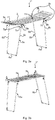
- Figs 1a and 1b show a first example of a clothes drying rack 1 which is foldable and arranged to be manoeuvrable between an unfolded state, in which the clothes drying rack 1 may be used for hanging wet garments, and a folded state in which the clothes drying rack 1 may be set when not in use.
- the clothes drying rack 1 has a frame 2, a first lateral wing 3a, a second lateral wing 3b, a first leg 5a and a second leg 5b.
- the first lateral wing 3a and the second lateral wing 3b form a lateral wing arrangement, and may thus together be referred to as a lateral wing arrangement.
- the first leg 5a and the second leg 5b form a leg arrangement, and may thus together be referred to as a leg arrangement. This applied to any example disclosed herein.
- the first lateral wing 3a is pivotally coupled to the frame 2.
- the first lateral wing 3a is pivotally coupled to a first end portion of the frame 2.
- the first lateral wing 3a is pivotable between an unfolded wing position shown in Fig. 1a , and a folded wing position relative to the frame 2, towards which the first lateral wing 3a is pivoted in Fig. 1b .
- the first lateral wing 3a is pivotable in a first rotational direction A when pivoted towards its folded wing position.
- the second lateral wing 3b is pivotally coupled to the frame 2.
- the second lateral wing 3b is pivotally coupled to a second end portion of the frame 2, the second end portion being opposite to the first end portion.
- the second lateral wing 3b is pivotable between an unfolded wing position shown in Fig. 1a , and a folded wing position relative to the frame 2, towards which the second lateral wing 3b is pivoted in Fig. 1b .
- the second lateral wing 3b is pivotable in a second rotational direction B when pivoted towards its folded wing position.
- the second rotational direction B is the direction opposite to the first rotational direction A.
- the first lateral wing 3a and the second lateral wing 3b are hence pivotable in opposite rotational directions towards each other.
- the clothes drying rack 1 can provide additional garment hanging space than what can be provided by the frame 2.
- the first leg 5a is pivotally coupled to the frame 2 and the second leg 5b is pivotally coupled to the frame 2.
- the first leg 5a is pivotally coupled to the first end portion of the frame 2 and the second leg 5b is pivotally coupled to the second end portion of the frame 2.
- the first leg 5a is pivotable between an unfolded leg position shown in Fig. 1a and a folded leg position relative to the frame 2, towards which the first leg 5a is pivoted in in Fig. 1b .
- the first leg 5a is pivotable towards its folded leg position in the second rotational direction B.
- the second leg 5b is pivotable between an unfolded leg position shown in Fig. 1a and a folded leg position relative to the frame 2, towards which the second leg 5a is pivoted in in Fig. 1b .
- the second leg 5b is pivotable towards its folded leg position in the first rotational direction A.
- first leg 5a and the second leg 5b are foldable towards each other towards an underside of the frame 2, wherein the first lateral wing 3a and the second lateral wing 3b are foldable towards each other towards an upper side of the frame 2.
- orientations “underside” and “upper side” is meant relative to a horizontal support surface upon which the clothes drying rack 1 is placed when in use.
- the first leg 5a and the second leg 5b hence function as frame support, arranged to support the frame 2 when the clothes drying rack 1 is in use.
- the clothes drying rack 1 also comprises a locking arrangement 4 which is fixedly arranged to the clothes drying rack 1.
- the locking arrangement 4 is arranged to interlock the lateral wing arrangement 3a, 3b with the leg arrangement 3a, 3b when the first lateral wing 3a and the second lateral wing 3b is in the folded wing position and the first leg 5a and the second leg 5b is in the folded leg position.
- the locking arrangement 4 is fixedly mounted to the first leg 5a and to the second leg 5b, but other variations are also possible.
- the locking arrangement may for example be fixedly arranged to the first lateral wing and to the second lateral wing, or to the frame.
- the locking arrangement 4 is not removable or at least not intended to be removed as the clothes drying rack is manoeuvred between its fully folded state and unfolded state; it forms a fixed part of the clothes drying rack which enables interlocking of the first leg, second leg, first lateral wing and second lateral wing when the clothes drying rack is fully folded and to allow the first leg, the second leg, the first lateral wing and the second lateral wing to be released from this interlocked state when the clothes drying rack is unfolded.
- the locking arrangement 4 is arranged to lock the first leg 5a to the first lateral wing 3a, and the second leg 5b to the second lateral wing 3b when the first leg 5a and the second leg 5b are in the folded leg position and the first lateral wing 3a and the second lateral wing 3b are in the folded wing position.
- the locking arrangement 4 is arranged to lock the first leg 5a to the second lateral wing 3b and the second leg 5b to the first lateral wing 3a when the first leg 5a and the second leg 5b are in the folded leg positon and the first lateral wing 3a and the second lateral wing 3b are in the folded wing position.
- the locking arrangement 4 comprises a first pair of locking members 7a, and a second pair of locking members 7b.
- the first pair of locking members 7a are arranged to interlock the first leg 5a with the first lateral wing 3a when the first leg 5a is in the folded leg position and the first lateral wing 3a is in the folded wing position. In this manner, the first lateral wing 3a maintains its folded wing position and the first leg 5a maintains its folded leg position when the clothes drying rack 1 is in its fully folded state.
- the first pair of locking members 7a are arranged to allow the first lateral wing 3a and the first leg 5a to be released from their folded positions when subjected to traction/rotational force larger than a threshold value. This may be the case when a user pivots the first lateral wing 3a and the first leg 5a towards their unfolded position, for example when it is desired to put the clothes drying rack 1 into use.
- the second pair of locking members 7b are arranged to interlock the second leg 5b with the second lateral wing 3b when the second leg 5b is in the folded leg position and the second lateral wing 3b is in the folded wing position. In this manner, the second lateral wing 3b maintains its folded wing position and the second leg 5b maintains its folded leg position.
- the second pair of locking members 7b are arranged to allow the second lateral wing 3b and the second leg 5b to be released from their folded positions when subjected to traction/rotational force larger than a threshold value. This may be the case when a user pivots the second lateral wing 3b and the second leg 5b towards their unfolded position, for example when it is desired to put the clothes drying rack 1 into use.
- first lateral wing 3a may be pivotally coupled to the first end portion of the frame 2 about a first pivot axis 9a.
- the first leg 5a may be pivotally coupled to the first end portion of the frame 2 about the first pivot axis 9a.
- second lateral wing 3b may be pivotally coupled to the second end portion of the frame 2 about a second pivot axis 9b.
- the second leg 5b may be pivotally coupled to the second end portion of the frame 2 about the second pivot axis 9b.
- first lateral wing 3a and the first leg 5a may have a common pivot axis
- the second lateral wing 3b and the second leg 5b may have a common pivot axis.
- the clothes drying rack 1 may have pivot joint members which pivotally couple the first leg 5a to the frame 2 and the first lateral wing 3a to the frame 2.
- the clothes drying rack 1 may also have pivot joint members which pivotally couple the second leg 5b to the frame 2 and the second lateral wing 3b to the frame 2.
- each one of the first pair of locking members 7a form part of a respective pivot joint member.
- each one of the second pair of locking members 7b form part of a respective pivot joint member.
- each pivot joint member may comprise a locking member.
- Figs 2a and 2b depict another example of a clothes drying rack 1'.
- Clothes drying rack 1' is similar to the clothes drying rack 1 presented in Figs 1a and 1b .
- Clothes drying rack 1' also has a frame 2, a first lateral wing 3a and a second lateral wing 3b, with the same functionality as clothes drying rack 1.
- Clothes drying rack 1' however differs from clothes drying rack 1 in that it has X-shaped legs.
- the X-shaped legs comprise a first leg 5a' and a second leg 5b'.
- the second leg 5b' has a knee 5c which enables the first leg 5a' and the second leg 5b' to be pivoted relative to the frame 2, and thus be set in their folded leg position, as partially shown in Fig. 2b .
- Clothes drying rack 1' also comprises a locking arrangement 4 arranged to interlock the lateral wing arrangement with the leg arrangement when the first lateral wing 3a and the second lateral wing 3b are in the folded wing position and the first leg 5a' and the second leg 5b' are in the folded leg position.
- the locking arrangement 4 may comprise a first pair of locking members 7a and a second pair of locking members 7b.
- FIG. 3a shows a perspective view of a clothes drying rack 1" having a frame 2, a first lateral wing 3a, a second lateral wing 3b, a first leg 5a and a second leg 5b.
- the clothes drying rack 1" furthermore comprises a locking arrangement in the form of a first pair of locking members 7a and a second pair of locking members 7b.
- the first lateral wing 3a and the first leg 5a are pivotable about a first pivot axis 9a.
- the second lateral wing 3b and the second leg 5b are pivotable about a second pivot axis 9b.
- the first leg 5a has a first longitudinal bar 6b and a second longitudinal bar 6c.
- the first longitudinal bar 6b and the second longitudinal bar 6c have a respective proximal end pivotally coupled to the frame 2, and a distal end, each of the first longitudinal bar 6b and the second longitudinal bar 6c extending from the frame 2 forming said first leg 5a.
- the first longitudinal bar 6b comprises a first locking member 7c of the first pair of locking members 7a.
- the first leg 5a also comprises two pivot joint members 11, which enables pivoting of the first leg 5a and of the first lateral wing 3a relative to the frame 2.
- the first locking member 7c of the first pair of locking members 7a forms part of one of the pivot joint members 11.
- the second longitudinal bar 6c of the first leg 5a comprises a second locking member of the first pair of locking members 7a.
- the second locking member of the first pair of locking members 7a forms part of the other pivot joint member 11 of the first leg 5a.
- the second leg 5b has a first longitudinal bar 6b and a second longitudinal bar 6c.
- the first longitudinal bar 6b and the second longitudinal bar 6c have a respective proximal end pivotally coupled to the frame 2, and a distal end, each of the first longitudinal bar 6b and the second longitudinal bar 6c extending from the frame 2 forming said second leg 5b.
- the first longitudinal bar 6b comprises a first locking member 7c of the second pair of locking members 7b.
- the second leg 5b also comprises two pivot joint members 11, which enables pivoting of the second leg 5b and of the second lateral wing 3b relative to the frame 2.
- the first locking member 7c of the second pair of locking members 7b forms part of one of the pivot joint members 11.
- the second longitudinal bar 6c of the second leg 5b comprises a second locking member of the second pair of locking members 7b.
- the second locking member of the second pair of locking members 7b forms part of the other pivot joint member 11 of the second leg 5b.
- the locking members 7c of the first leg 5a are arranged close to the first pivot axis 9a along the first leg 5a, not more than a distance of one fourth of the length of a corresponding longitudinal bar from the first pivot axis 9a, preferably less than one fifth of the distance.
- the locking members 7c of the second leg 5b are arranged close to the second pivot axis 9b along the second leg 5b, not more than a distance of one fourth of the length of a corresponding longitudinal bar from the second pivot axis 9b, preferably less than one fifth of the distance.
- the legs 5a, 5b may be tapering towards the foot 6a and/or the lateral wings 3a, 3b may be tapering towards their outer ends relative to their respective pivot axes, in order to enable full folding of the clothes drying rack 1", and a location of the locking members further away from the pivot axes would render it difficult to obtain the desired interlocking effect of the frame, legs and lateral wings.
- Fig. 3b shows the clothes drying rack 1" in a partially folded state.
- the first lateral wing 3a and the second lateral wing 3b have been fully folded towards the frame 5.
- Fig. 3c the clothes drying rack 1" is shown in a fully folded state.
- the first pair of locking members 7a interlock the first leg 5a with the first lateral wing 3a.
- the second pair of locking members 7b interlock the second leg 5b and the second lateral wing 3b.
- Fig. 4 depicts an example of a locking member 7c, which may be any single locking member of the first pair of locking members 7a and the second pair of locking members 7b.
- the pivot joint member 11 forms the end portion of a longitudinal bar 6b, 6c, in this example the first longitudinal bar 6b.
- the pivot joint member 11 is hence attachable to the frame 2 to enable pivoting about the first pivot axis 9a.
- the locking member 7c has a fin 7d which is arranged to engage with and interlock the frame 2 and the first lateral wing 3a when the first leg 5a is in the folded leg position and the first lateral wing 3a is in the folded wing position.
- the fins 7d may according to one variation be made of a rigid material such as a plastic or metal.
- the fin has a first groove 7e for receiving a portion of the first lateral wing 3a and a second groove 7f, essentially parallel to the first groove 7e, for receiving a portion of the frame 2 when the clothes drying rack 1" is in the fully folded state.
- the first groove 7e and the second groove 7f are arranged on opposite sides of the fin 7d, and are substantially parallel to the first longitudinal bar 6b. This structure applies to all of the locking members of the clothes drying rack 1".
- the fins 7d of two opposite locking members 7c of the first leg 5a and the second leg 5b point towards each other when both the first leg 5a and the second leg 5b are set in their unfolded leg positions.
- the fins 7d of the first leg 5a hence point in the second direction B and the fins 7d of the second leg 5b point in the first direction A.
- the pivot joint member 11 has a frame receiving groove 11a which extends transversely relative to the first pivot axis 9a.
- the frame receiving groove 11a is arranged to receive a portion of the frame 2 when the corresponding leg 5a, 5b is in the unfolded leg position.
- the fins 7d of the first leg 5a are forced between the frame 2 and the first lateral wing 3a and the fins 7d of the second leg 5b are forced between the frame 2 and the second lateral wing 3b when the clothes drying rack 1" is set in its fully folded state.
- One of the lateral wings 3a, 3b is hence received in the first groove 7e and the frame 2 is hence received in the second groove 7f.
- the width of the frame 2 is greater than the width of the first lateral wing 3a
- the width of the first leg 5a is greater than the width of the first lateral wing 3a but smaller than the width of the frame 2, at a location where the first pair of locking members 7a engage the first lateral wing 3a when the clothes drying rack 1" is in a fully folded state.
- width is here meant the width across from one end to the opposite end e.g. from one side of the frame to the opposite side in a direction parallel with the first pivot axis 9a.
- the width of the frame 2 is greater than the width of the second lateral wing 3b
- the width of the second leg 5b is greater than the width of the second lateral wing 3b but smaller than the width of the frame 2, at a location where the second pair of locking members 7b engage the second lateral wing 3b when the clothes drying rack 1" is in a fully folded state.
- the fins 7d are hence with regards to width arranged between the lateral wings 3a, 3b and the frame 2. As a result each fin 7d is squeezed between a lateral wing 3a, 3b and the frame 2 when the clothes drying rack 1" is being set in the fully folded state.
- Each fin 7d preferably has an elevated end portion 7g which is elevated relative to both the first groove 7e and the second groove 7f.
- the fin 7d is wider than its width at the first groove 7e and second groove 7f.
- the width w of the fin 7d at the elevated end portion 7g is preferably greater than the distance d between the frame 2 and a lateral wing 3a, 3b, as shown in Fig. 5 .
- One of the lateral wings 3a, 3b and the frame 2 will thereby be maintained in the first groove 7e and the second groove 7f, respectively, of a locking member 7c when the clothes drying rack 1" is in the fully folded state.
- Fig. 6 shows a cross section of the fully folded clothes drying rack 1" along lines II-II in Fig. 3c . It may be seen that a portion of the lateral wing, in this example the first lateral wing 3a, has been received by the first groove 7e of the fin 7d and that a portion of the frame 2 has been received in the second groove 7f.
- the elevated end portion 7g maintains the frame 2 and the lateral wing in their respective grooves 7e and 7f until they are released by force, for example when the clothes drying rack 1" is unfolded by a user.
- the fin may have a rotatable top part, corresponding to the elevated end portion of the example above, which rotatable top part is manually manoeuvred to be parallel or essentially parallel with its associated longitudinal bar when the clothes drying rack is being folded and set in its fully folded state.
- a user may then manually rotate the top part e.g. 90 degrees of each fin to maintain the clothes drying rack in its fully folded state and prevent it from unfolding.
- the top part is again rotated such that the fins may be slid between their respective lateral wings and frame, enabling the clothes drying rack to be set in its unfolded state.
- the fins are provided with biased protrusion members each of which may be manoeuvred between a retracted position and an extended position along the axis along which it is biased.
- Each protrusion member may for example be biased by means of a spring.
- the protrusion members are arranged to form the elevated end portion of each fin. The protrusion members are retracted when passed between the frame and a lateral wing, and due to the biasing extended when having passed through, thus providing an interlocking effect.
- each fin comprises a blocking arrangement arranged to prevent movement of a leg 5a, 5b and a lateral wing 3a, 3b when the leg in question is in the folded leg position and the lateral wing in question is in the folded leg position.
- FIG. 7a shows a clothes drying rack which has the locking arrangement mounted to the first lateral wing and to the second lateral wing.
- the locking arrangement hence comprises a first pair of locking members arranged on the first lateral wing and a second pair of locking members arranged on the second lateral wing.
- Fig. 7b shows a clothes drying rack which has the locking arrangement mounted to the frame.
- the locking arrangement 4 may comprise a first pair of locking members for interlocking the first lateral wing and the first leg, and a second pair of locking members for interlocking the second lateral wing and the second leg.
- Fig. 7c shows a clothes drying rack which has a locking arrangement fixedly mounted to the first leg and the second leg.
- the locking arrangement comprises a first pair of locking members arranged at the distal end of the first leg and a second pair of locking members arranged at the distal end of the second leg.
- This configuration may be realised in case the longitudinal bars of the legs do not approach each other in a tapering manner in the direction from the proximal end to the distal end, but are instead essentially parallel.
- Fig. 7d shows a clothes drying rack which has telescopic pivotable legs relative to the frame.
- the first lateral wing and the second lateral wing comprise the locking arrangement 4.
- the locking arrangement comprises a first locking member attached to the first lateral wing and a second locking member attached to the second lateral wing, preferably to their distal ends beams, e.g. a respective beam which is parallel to the first pivot axis and second pivot axis.
- the locking members are arranged to interlock a respective one of the first leg and the second leg when they have been retracted and folded towards the frame, and when the first lateral wing and the second lateral wing have been folded to their folded wing position.
- Fig. 7e shows yet another example of a clothes drying rack having a locking arrangement 4.
- the proximal end of the second leg is slidably arranged relative to the frame and is slidable towards the first leg in order to fold the first leg and the second leg to obtain their folded leg positions.
- the first leg may have a rung arranged between its two longitudinal bars, wherein a locking member of the locking arrangement 4 may be arranged on the rung, and a respective locking member may be arranged on the distal end portions of the first lateral wing and the second lateral wing.
- the locking members of the lateral wings may engage the locking member of the rung such that the clothes drying rack maintains its fully folded state.
- Fig. 7f shows a clothes drying rack which has a knee portion for folding its X-legged structure.
- a rung may extend between the two parallel longitudinal bars of the first leg comprising the knee portion, and extending in level with the knee portion.
- the locking arrangement 4 may be arranged at the rung and/or at a distal end of one or both of the lateral wings.
- the structure of the locking member should be modified in comparison to the locking members 7c described in more detail hereabove.
Landscapes
- Engineering & Computer Science (AREA)
- Textile Engineering (AREA)
- Assembled Shelves (AREA)
Description
- The present disclosure generally relates to clothes drying racks. In particular, it relates to a foldable clothes drying rack.
- Clothes drying racks of the foldable type may comprise a main frame, two lateral wings which are pivotally coupled to opposite ends of the main frame, and legs that are pivotally coupled to the main frame. The lateral wings may be foldable towards each other, and the legs may be placed in a folded position towards the main frame, thus minimising the size of the clothes drying rack when not in use.
- When a clothes drying rack has been placed in its folded state by folding of the legs and lateral wings, there is a risk that the legs and/or lateral wings will unfold when handling the clothes drying rack, for example when moved from one location to another.
- There are several existing solutions for maintaining a clothes drying rack in a folded state. The utility model
DE202004009881 , for example, discloses a clothes dryer that has a holding clamp for holding the lateral wings of the clothes dryer so that the dryer can be stored in the vertical position after use without the lateral wings unfolding from the main frame. The clamp is placed around portions of the lateral wings which face each other in the folded position, thus locking the lateral wings in this position. -
WO2005113882 shows another example of a clothes drying rack which has lateral wings that are fixed when the clothes drying rack is folded. In particular, each lateral wing is folded towards a respective leg and fixed thereto, wherein both legs are folded towards the main frame to obtain a folded clothes drying rack. -
DE202004009881 relies on clamps that are external to the clothes drying rack for locking the lateral wings in the folded position. - In view of the above, an object of the present disclosure is to solve, or at least mitigate, the problems of the prior art.
- There is hence provided a clothes drying rack comprising a frame, a first lateral wing pivotally coupled to a first end portion of the frame, a second lateral wing pivotally coupled to a second end portion of the frame, each of the first lateral wing and the second lateral wing being pivotable between a folded wing position relative to the frame, the first lateral wing and the second lateral wing being foldable towards each other to obtain their folded wing position, and an unfolded wing position relative to the frame, wherein the first lateral wing is pivotable in a first rotational direction to obtain its folded wing position and the second lateral wing is pivotable in a second rotational direction, opposite to the first rotational direction, to obtain its folded wing position, a first leg pivotally coupled to the first end portion of the frame, wherein the first leg is pivotable between a folded leg position and an unfolded leg position relative to the frame, wherein the first leg is pivotable in the second rotational direction to obtain its folded leg position, a second leg pivotally coupled to the second end portion of the frame, wherein the second leg is pivotable between a folded leg position and an unfolded leg position relative to the frame, and a locking arrangement fixedly mounted to the clothes drying rack, wherein the first lateral wing and the second lateral wing form a lateral wing arrangement and the first leg and the second leg form a leg arrangement, and wherein the locking arrangement is arranged to interlock the lateral wing arrangement with the leg arrangement when the first leg and the second leg is in the folded leg position and the first lateral wing and the second lateral wing is in the folded wing position.
- Hence the clothes drying rack remains in its folded state when the legs and the lateral wings have obtained their folded leg positions and folded wing positions, respectively. In particular, this may be obtained in a simple manner as a consequence of folding of the legs and the lateral wings, without the utilisation of any external means.
- According to one embodiment the locking arrangement is arranged to interlock the first leg with one of the first lateral wing and the second lateral wing, and to interlock the second leg with the other one of the first lateral wing and the second lateral wing when the first leg and the second leg are in the folded leg position and the first lateral wing and the second lateral wing are in the folded wing position.
- According to one embodiment the second leg is pivotable in the first rotational direction to obtain its folded leg position.
- According to one embodiment the locking arrangement comprises a first pair of locking members arranged to interlock the first leg with the first lateral wing when the first lateral wing is in the folded wing position and the first leg is in the folded leg position thereby maintaining the first leg in the folded leg position and the first lateral wing in the folded wing position, and a second pair of locking members arranged to interlock the second leg with the second lateral wing when the second lateral wing is in the folded wing position and the second leg is in the folded leg position thereby maintaining the second leg in the folded leg position and the second lateral wing in the folded wing position.
- According to one embodiment the locking arrangement comprises a first pair of locking members arranged to interlock the first leg with the second lateral wing when the second lateral wing is in the folded wing position and the first leg is in the folded leg position thereby maintaining the first leg in the folded leg position and the second lateral wing in the folded wing position, and a second pair of locking members arranged to interlock the second leg with the first lateral wing when the first lateral wing is in the folded wing position and the second leg is in the folded leg position thereby maintaining the second leg in the folded leg position and the first lateral wing in the folded wing position.
- According to one embodiment each of the first pair of locking members is arranged to interlock the first leg with the frame when the first leg is in the folded leg position, and wherein each of the second pair of locking member is arranged to interlock the second leg with the frame when the second leg is in the folded leg position.
- According to one embodiment each of the first pair of locking members has a fin provided with a first groove at a first side thereof for receiving a portion of a lateral wing and with a second groove at a second side opposite to the first side for receiving a portion of the frame.
- According to one embodiment each locking member of the first pair of locking members forms part of a pivot joint member which pivotally couples the first leg to the frame.
- According to one embodiment each of the second pair of locking members has a fin provided with a first groove at a first side thereof for receiving a portion of a lateral wing and with a second groove at a second side opposite to the first side for receiving a portion of the frame.
- According to one embodiment each fin is made of a rigid material.
- According to one embodiment each locking member of the second pair of locking members forms part of a pivot joint member which pivotally couples the second leg to the frame.
- According to one embodiment the first leg has a first longitudinal bar and a second longitudinal bar, the first longitudinal bar and the second longitudinal bar extending from the frame, wherein the first leg comprises a first locking member of the first pair of locking members and the second longitudinal bar comprises a second locking member of the first pair of locking members.
- According to one embodiment the second leg has a first longitudinal bar and a second longitudinal bar, the first longitudinal bar and the second longitudinal bar extending from the frame, wherein the second leg comprises a first locking member of the second pair of locking members and the second longitudinal bar comprises a second locking member of the second pair of locking members.
- According to one embodiment the first lateral wing is pivotally coupled to the first end portion of the frame about a first pivot axis, and wherein the first leg is pivotally coupled to the first end portion of the frame about the first pivot axis.
- According to one embodiment the second lateral wing is pivotally coupled to the second end portion of the frame about a second pivot axis, and wherein the second leg is pivotally coupled to the second end portion of the frame about the second pivot axis.
- According to one embodiment the width of the frame is greater than the width of the first lateral wing, and the width of the first legs is greater than the width of the first lateral wing but smaller than the width of the frame, at a location where the first pair of locking members engage the first lateral wing when the clothes drying rack is in a fully folded state and wherein the width of the frame is greater than the width of the second lateral wing, and the width of the second legs is greater than the width of the second lateral wing but smaller than the width of the frame, at a location where the second pair of locking members engage the second lateral wing when the clothes drying rack is in a fully folded state.
- Generally, all terms used in the claims are to be interpreted according to their ordinary meaning in the technical field, unless explicitly defined otherwise herein. All references to "a/an/the element, apparatus, component, means, etc. are to be interpreted openly as referring to at least one instance of the element, apparatus, component, means, etc., unless explicitly stated otherwise.
- The specific embodiments of the inventive concept will now be described, by way of example, with reference to the accompanying drawings, in which:
-
Fig. 1a is a schematic side view of an example of a clothes drying rack in an unfolded state; -
Fig. 1b is a schematic side view of the clothes drying rack inFig. 1a partially folded; -
Fig. 2a is a schematic side view of another example of a clothes drying rack in an unfolded state; -
Fig. 2b is a schematic side view of the clothes drying rack inFig. 1b partially folded; -
Figs 3a-3c show perspective view of an example of a clothes drying rack in the open state, in a partially folded state, and a fully folded state; -
Fig. 4 shows a perspective view of a locking member of the clothes drying rack inFigs 3a-3c ; -
Fig. 5 shows a top view of a portion of the clothes drying rack inFig. 3c ; -
Fig. 6 shows a perspective view of a cross section of the clothes drying rack inFig. 3c , taken at II-II; and -
Figs 7a-7f show a number of variations of a clothes drying rack. - The inventive concept will now be described more fully hereinafter with reference to the accompanying drawings, in which exemplifying embodiments are shown. The inventive concept may, however, be embodied in many different forms and should not be construed as limited to the embodiments set forth herein; rather, these embodiments are provided by way of example so that this disclosure will be thorough and complete, and will fully convey the scope of the inventive concept to those skilled in the art. Like numbers refer to like elements throughout the description.
-
Figs 1a and 1b show a first example of aclothes drying rack 1 which is foldable and arranged to be manoeuvrable between an unfolded state, in which theclothes drying rack 1 may be used for hanging wet garments, and a folded state in which theclothes drying rack 1 may be set when not in use. - The
clothes drying rack 1 has aframe 2, a firstlateral wing 3a, a secondlateral wing 3b, afirst leg 5a and asecond leg 5b. The firstlateral wing 3a and the secondlateral wing 3b form a lateral wing arrangement, and may thus together be referred to as a lateral wing arrangement. Thefirst leg 5a and thesecond leg 5b form a leg arrangement, and may thus together be referred to as a leg arrangement. This applied to any example disclosed herein. - The first
lateral wing 3a is pivotally coupled to theframe 2. In particular, the firstlateral wing 3a is pivotally coupled to a first end portion of theframe 2. The firstlateral wing 3a is pivotable between an unfolded wing position shown inFig. 1a , and a folded wing position relative to theframe 2, towards which the firstlateral wing 3a is pivoted inFig. 1b . The firstlateral wing 3a is pivotable in a first rotational direction A when pivoted towards its folded wing position. - The second
lateral wing 3b is pivotally coupled to theframe 2. In particular, the secondlateral wing 3b is pivotally coupled to a second end portion of theframe 2, the second end portion being opposite to the first end portion. The secondlateral wing 3b is pivotable between an unfolded wing position shown inFig. 1a , and a folded wing position relative to theframe 2, towards which the secondlateral wing 3b is pivoted inFig. 1b . The secondlateral wing 3b is pivotable in a second rotational direction B when pivoted towards its folded wing position. The second rotational direction B is the direction opposite to the first rotational direction A. The firstlateral wing 3a and the secondlateral wing 3b are hence pivotable in opposite rotational directions towards each other. - By means of the first
lateral wing 3a and the secondlateral wing 3b theclothes drying rack 1 can provide additional garment hanging space than what can be provided by theframe 2. - The
first leg 5a is pivotally coupled to theframe 2 and thesecond leg 5b is pivotally coupled to theframe 2. Thefirst leg 5a is pivotally coupled to the first end portion of theframe 2 and thesecond leg 5b is pivotally coupled to the second end portion of theframe 2. - The
first leg 5a is pivotable between an unfolded leg position shown inFig. 1a and a folded leg position relative to theframe 2, towards which thefirst leg 5a is pivoted in inFig. 1b . Thefirst leg 5a is pivotable towards its folded leg position in the second rotational direction B. - The
second leg 5b is pivotable between an unfolded leg position shown inFig. 1a and a folded leg position relative to theframe 2, towards which thesecond leg 5a is pivoted in inFig. 1b . Thesecond leg 5b is pivotable towards its folded leg position in the first rotational direction A. - Hence, the
first leg 5a and thesecond leg 5b are foldable towards each other towards an underside of theframe 2, wherein the firstlateral wing 3a and the secondlateral wing 3b are foldable towards each other towards an upper side of theframe 2. With the orientations "underside" and "upper side" is meant relative to a horizontal support surface upon which theclothes drying rack 1 is placed when in use. - The
first leg 5a and thesecond leg 5b hence function as frame support, arranged to support theframe 2 when theclothes drying rack 1 is in use. - The
clothes drying rack 1 also comprises alocking arrangement 4 which is fixedly arranged to theclothes drying rack 1. Generally speaking, the lockingarrangement 4 is arranged to interlock thelateral wing arrangement leg arrangement lateral wing 3a and the secondlateral wing 3b is in the folded wing position and thefirst leg 5a and thesecond leg 5b is in the folded leg position. - According to the example in
Fig. 1a , the lockingarrangement 4 is fixedly mounted to thefirst leg 5a and to thesecond leg 5b, but other variations are also possible. The locking arrangement may for example be fixedly arranged to the first lateral wing and to the second lateral wing, or to the frame. With "fixedly arranged" or "fixedly mounted" is meant that the lockingarrangement 4 is not removable or at least not intended to be removed as the clothes drying rack is manoeuvred between its fully folded state and unfolded state; it forms a fixed part of the clothes drying rack which enables interlocking of the first leg, second leg, first lateral wing and second lateral wing when the clothes drying rack is fully folded and to allow the first leg, the second leg, the first lateral wing and the second lateral wing to be released from this interlocked state when the clothes drying rack is unfolded. - According to one variation the locking
arrangement 4 is arranged to lock thefirst leg 5a to the firstlateral wing 3a, and thesecond leg 5b to the secondlateral wing 3b when thefirst leg 5a and thesecond leg 5b are in the folded leg position and the firstlateral wing 3a and the secondlateral wing 3b are in the folded wing position. According to another variation, the lockingarrangement 4 is arranged to lock thefirst leg 5a to the secondlateral wing 3b and thesecond leg 5b to the firstlateral wing 3a when thefirst leg 5a and thesecond leg 5b are in the folded leg positon and the firstlateral wing 3a and the secondlateral wing 3b are in the folded wing position. - According to one variation the locking
arrangement 4 comprises a first pair of lockingmembers 7a, and a second pair of lockingmembers 7b. The first pair of lockingmembers 7a are arranged to interlock thefirst leg 5a with the firstlateral wing 3a when thefirst leg 5a is in the folded leg position and the firstlateral wing 3a is in the folded wing position. In this manner, the firstlateral wing 3a maintains its folded wing position and thefirst leg 5a maintains its folded leg position when theclothes drying rack 1 is in its fully folded state. The first pair of lockingmembers 7a are arranged to allow the firstlateral wing 3a and thefirst leg 5a to be released from their folded positions when subjected to traction/rotational force larger than a threshold value. This may be the case when a user pivots the firstlateral wing 3a and thefirst leg 5a towards their unfolded position, for example when it is desired to put theclothes drying rack 1 into use. - The second pair of locking
members 7b are arranged to interlock thesecond leg 5b with the secondlateral wing 3b when thesecond leg 5b is in the folded leg position and the secondlateral wing 3b is in the folded wing position. In this manner, the secondlateral wing 3b maintains its folded wing position and thesecond leg 5b maintains its folded leg position. The second pair of lockingmembers 7b are arranged to allow the secondlateral wing 3b and thesecond leg 5b to be released from their folded positions when subjected to traction/rotational force larger than a threshold value. This may be the case when a user pivots the secondlateral wing 3b and thesecond leg 5b towards their unfolded position, for example when it is desired to put theclothes drying rack 1 into use. - According to one variation the first
lateral wing 3a may be pivotally coupled to the first end portion of theframe 2 about afirst pivot axis 9a. Thefirst leg 5a may be pivotally coupled to the first end portion of theframe 2 about thefirst pivot axis 9a. Furthermore the secondlateral wing 3b may be pivotally coupled to the second end portion of theframe 2 about asecond pivot axis 9b. Thesecond leg 5b may be pivotally coupled to the second end portion of theframe 2 about thesecond pivot axis 9b. To this end, the firstlateral wing 3a and thefirst leg 5a may have a common pivot axis, and the secondlateral wing 3b and thesecond leg 5b may have a common pivot axis. - The
clothes drying rack 1 may have pivot joint members which pivotally couple thefirst leg 5a to theframe 2 and the firstlateral wing 3a to theframe 2. Theclothes drying rack 1 may also have pivot joint members which pivotally couple thesecond leg 5b to theframe 2 and the secondlateral wing 3b to theframe 2. According to one variation, each one of the first pair of lockingmembers 7a form part of a respective pivot joint member. Moreover, each one of the second pair of lockingmembers 7b form part of a respective pivot joint member. To this end, each pivot joint member may comprise a locking member. -
Figs 2a and 2b depict another example of a clothes drying rack 1'. Clothes drying rack 1' is similar to theclothes drying rack 1 presented inFigs 1a and 1b . Clothes drying rack 1' also has aframe 2, a firstlateral wing 3a and a secondlateral wing 3b, with the same functionality asclothes drying rack 1. Clothes drying rack 1' however differs fromclothes drying rack 1 in that it has X-shaped legs. The X-shaped legs comprise afirst leg 5a' and asecond leg 5b'. Thesecond leg 5b' has aknee 5c which enables thefirst leg 5a' and thesecond leg 5b' to be pivoted relative to theframe 2, and thus be set in their folded leg position, as partially shown inFig. 2b . - Clothes drying rack 1' also comprises a
locking arrangement 4 arranged to interlock the lateral wing arrangement with the leg arrangement when the firstlateral wing 3a and the secondlateral wing 3b are in the folded wing position and thefirst leg 5a' and thesecond leg 5b' are in the folded leg position. The lockingarrangement 4 may comprise a first pair of lockingmembers 7a and a second pair of lockingmembers 7b. - An example of a clothes drying rack will now be described in more detail with reference to
Figs 3a to 6 . This clothes drying rack has legs of the type shown inFigs 1a and 1b , but its function and structure with regards to the locking mechanisms also applied to clothes drying racks with X-shaped legs.Fig. 3a shows a perspective view of aclothes drying rack 1" having aframe 2, a firstlateral wing 3a, a secondlateral wing 3b, afirst leg 5a and asecond leg 5b. Theclothes drying rack 1" furthermore comprises a locking arrangement in the form of a first pair of lockingmembers 7a and a second pair of lockingmembers 7b. The firstlateral wing 3a and thefirst leg 5a are pivotable about afirst pivot axis 9a. The secondlateral wing 3b and thesecond leg 5b are pivotable about asecond pivot axis 9b. - The
first leg 5a has a firstlongitudinal bar 6b and a secondlongitudinal bar 6c. The firstlongitudinal bar 6b and the secondlongitudinal bar 6c have a respective proximal end pivotally coupled to theframe 2, and a distal end, each of the firstlongitudinal bar 6b and the secondlongitudinal bar 6c extending from theframe 2 forming saidfirst leg 5a. The firstlongitudinal bar 6b comprises afirst locking member 7c of the first pair of lockingmembers 7a. Thefirst leg 5a also comprises two pivotjoint members 11, which enables pivoting of thefirst leg 5a and of the firstlateral wing 3a relative to theframe 2. Thefirst locking member 7c of the first pair of lockingmembers 7a forms part of one of the pivotjoint members 11. The secondlongitudinal bar 6c of thefirst leg 5a comprises a second locking member of the first pair of lockingmembers 7a. The second locking member of the first pair of lockingmembers 7a forms part of the other pivotjoint member 11 of thefirst leg 5a. - The
second leg 5b has a firstlongitudinal bar 6b and a secondlongitudinal bar 6c. The firstlongitudinal bar 6b and the secondlongitudinal bar 6c have a respective proximal end pivotally coupled to theframe 2, and a distal end, each of the firstlongitudinal bar 6b and the secondlongitudinal bar 6c extending from theframe 2 forming saidsecond leg 5b. The firstlongitudinal bar 6b comprises afirst locking member 7c of the second pair of lockingmembers 7b. Thesecond leg 5b also comprises two pivotjoint members 11, which enables pivoting of thesecond leg 5b and of the secondlateral wing 3b relative to theframe 2. Thefirst locking member 7c of the second pair of lockingmembers 7b forms part of one of the pivotjoint members 11. The secondlongitudinal bar 6c of thesecond leg 5b comprises a second locking member of the second pair of lockingmembers 7b. The second locking member of the second pair of lockingmembers 7b forms part of the other pivotjoint member 11 of thesecond leg 5b. - According to the example, the locking
members 7c of thefirst leg 5a are arranged close to thefirst pivot axis 9a along thefirst leg 5a, not more than a distance of one fourth of the length of a corresponding longitudinal bar from thefirst pivot axis 9a, preferably less than one fifth of the distance. The lockingmembers 7c of thesecond leg 5b are arranged close to thesecond pivot axis 9b along thesecond leg 5b, not more than a distance of one fourth of the length of a corresponding longitudinal bar from thesecond pivot axis 9b, preferably less than one fifth of the distance. This is due to the fact that thelegs foot 6a and/or thelateral wings clothes drying rack 1", and a location of the locking members further away from the pivot axes would render it difficult to obtain the desired interlocking effect of the frame, legs and lateral wings. -
Fig. 3b shows theclothes drying rack 1" in a partially folded state. In particular, the firstlateral wing 3a and the secondlateral wing 3b have been fully folded towards the frame 5. InFig. 3c theclothes drying rack 1" is shown in a fully folded state. The first pair of lockingmembers 7a interlock thefirst leg 5a with the firstlateral wing 3a. The second pair of lockingmembers 7b interlock thesecond leg 5b and the secondlateral wing 3b. -
Fig. 4 depicts an example of a lockingmember 7c, which may be any single locking member of the first pair of lockingmembers 7a and the second pair of lockingmembers 7b. The pivotjoint member 11 forms the end portion of alongitudinal bar longitudinal bar 6b. The pivotjoint member 11 is hence attachable to theframe 2 to enable pivoting about thefirst pivot axis 9a. - The locking
member 7c has afin 7d which is arranged to engage with and interlock theframe 2 and the firstlateral wing 3a when thefirst leg 5a is in the folded leg position and the firstlateral wing 3a is in the folded wing position. Thefins 7d may according to one variation be made of a rigid material such as a plastic or metal. The fin has afirst groove 7e for receiving a portion of the firstlateral wing 3a and asecond groove 7f, essentially parallel to thefirst groove 7e, for receiving a portion of theframe 2 when theclothes drying rack 1" is in the fully folded state. Thefirst groove 7e and thesecond groove 7f are arranged on opposite sides of thefin 7d, and are substantially parallel to the firstlongitudinal bar 6b. This structure applies to all of the locking members of theclothes drying rack 1". - The
fins 7d of twoopposite locking members 7c of thefirst leg 5a and thesecond leg 5b point towards each other when both thefirst leg 5a and thesecond leg 5b are set in their unfolded leg positions. Thefins 7d of thefirst leg 5a hence point in the second direction B and thefins 7d of thesecond leg 5b point in the first direction A. - The pivot
joint member 11 has aframe receiving groove 11a which extends transversely relative to thefirst pivot axis 9a. Theframe receiving groove 11a is arranged to receive a portion of theframe 2 when thecorresponding leg - The
fins 7d of thefirst leg 5a are forced between theframe 2 and the firstlateral wing 3a and thefins 7d of thesecond leg 5b are forced between theframe 2 and the secondlateral wing 3b when theclothes drying rack 1" is set in its fully folded state. One of thelateral wings first groove 7e and theframe 2 is hence received in thesecond groove 7f. The width of theframe 2 is greater than the width of the firstlateral wing 3a, and the width of thefirst leg 5a is greater than the width of the firstlateral wing 3a but smaller than the width of theframe 2, at a location where the first pair of lockingmembers 7a engage the firstlateral wing 3a when theclothes drying rack 1" is in a fully folded state. With "width" is here meant the width across from one end to the opposite end e.g. from one side of the frame to the opposite side in a direction parallel with thefirst pivot axis 9a. Similarly, the width of theframe 2 is greater than the width of the secondlateral wing 3b, and the width of thesecond leg 5b is greater than the width of the secondlateral wing 3b but smaller than the width of theframe 2, at a location where the second pair of lockingmembers 7b engage the secondlateral wing 3b when theclothes drying rack 1" is in a fully folded state. Thefins 7d are hence with regards to width arranged between thelateral wings frame 2. As a result eachfin 7d is squeezed between alateral wing frame 2 when theclothes drying rack 1" is being set in the fully folded state. - Each
fin 7d preferably has anelevated end portion 7g which is elevated relative to both thefirst groove 7e and thesecond groove 7f. Here, thefin 7d is wider than its width at thefirst groove 7e andsecond groove 7f. The width w of thefin 7d at theelevated end portion 7g is preferably greater than the distance d between theframe 2 and alateral wing Fig. 5 . One of thelateral wings frame 2 will thereby be maintained in thefirst groove 7e and thesecond groove 7f, respectively, of a lockingmember 7c when theclothes drying rack 1" is in the fully folded state. -
Fig. 6 shows a cross section of the fully foldedclothes drying rack 1" along lines II-II inFig. 3c . It may be seen that a portion of the lateral wing, in this example the firstlateral wing 3a, has been received by thefirst groove 7e of thefin 7d and that a portion of theframe 2 has been received in thesecond groove 7f. Theelevated end portion 7g maintains theframe 2 and the lateral wing in theirrespective grooves clothes drying rack 1" is unfolded by a user. - According to one variation the fin may have a rotatable top part, corresponding to the elevated end portion of the example above, which rotatable top part is manually manoeuvred to be parallel or essentially parallel with its associated longitudinal bar when the clothes drying rack is being folded and set in its fully folded state. A user may then manually rotate the top part e.g. 90 degrees of each fin to maintain the clothes drying rack in its fully folded state and prevent it from unfolding. When the clothes drying rack is to be unfolded, the top part is again rotated such that the fins may be slid between their respective lateral wings and frame, enabling the clothes drying rack to be set in its unfolded state.
- According to another variation, the fins are provided with biased protrusion members each of which may be manoeuvred between a retracted position and an extended position along the axis along which it is biased. Each protrusion member may for example be biased by means of a spring. The protrusion members are arranged to form the elevated end portion of each fin. The protrusion members are retracted when passed between the frame and a lateral wing, and due to the biasing extended when having passed through, thus providing an interlocking effect.
- Thus, generally for each of the above examples of the fin, each fin comprises a blocking arrangement arranged to prevent movement of a
leg lateral wing - Further examples of a clothes drying rack will be described with reference to
Figs 7a-7f , with different configurations of alocking arrangement 4.Fig. 7a shows a clothes drying rack which has the locking arrangement mounted to the first lateral wing and to the second lateral wing. The locking arrangement hence comprises a first pair of locking members arranged on the first lateral wing and a second pair of locking members arranged on the second lateral wing. -
Fig. 7b shows a clothes drying rack which has the locking arrangement mounted to the frame. The lockingarrangement 4 may comprise a first pair of locking members for interlocking the first lateral wing and the first leg, and a second pair of locking members for interlocking the second lateral wing and the second leg. -
Fig. 7c shows a clothes drying rack which has a locking arrangement fixedly mounted to the first leg and the second leg. The locking arrangement comprises a first pair of locking members arranged at the distal end of the first leg and a second pair of locking members arranged at the distal end of the second leg. This configuration may be realised in case the longitudinal bars of the legs do not approach each other in a tapering manner in the direction from the proximal end to the distal end, but are instead essentially parallel. -
Fig. 7d shows a clothes drying rack which has telescopic pivotable legs relative to the frame. The first lateral wing and the second lateral wing comprise thelocking arrangement 4. The locking arrangement comprises a first locking member attached to the first lateral wing and a second locking member attached to the second lateral wing, preferably to their distal ends beams, e.g. a respective beam which is parallel to the first pivot axis and second pivot axis. The locking members are arranged to interlock a respective one of the first leg and the second leg when they have been retracted and folded towards the frame, and when the first lateral wing and the second lateral wing have been folded to their folded wing position. -
Fig. 7e shows yet another example of a clothes drying rack having a lockingarrangement 4. According to this example the proximal end of the second leg is slidably arranged relative to the frame and is slidable towards the first leg in order to fold the first leg and the second leg to obtain their folded leg positions. The first leg may have a rung arranged between its two longitudinal bars, wherein a locking member of thelocking arrangement 4 may be arranged on the rung, and a respective locking member may be arranged on the distal end portions of the first lateral wing and the second lateral wing. When the clothes drying rack is fully folded, the locking members of the lateral wings may engage the locking member of the rung such that the clothes drying rack maintains its fully folded state. -
Fig. 7f shows a clothes drying rack which has a knee portion for folding its X-legged structure. A rung may extend between the two parallel longitudinal bars of the first leg comprising the knee portion, and extending in level with the knee portion. The lockingarrangement 4 may be arranged at the rung and/or at a distal end of one or both of the lateral wings. - In some of the examples above, the structure of the locking member should be modified in comparison to the locking
members 7c described in more detail hereabove. - The inventive concept has mainly been described above with reference to a few examples. However, as is readily appreciated by a person skilled in the art, other embodiments than the ones disclosed above are equally possible within the scope of the inventive concept, as defined by the appended claims.
Claims (12)
- A clothes drying rack (1; 1'; 1") comprising:a frame (2),a first lateral wing (3a) pivotally coupled to a first end portion of the frame (2),a second lateral wing (3b) pivotally coupled to a second end portion of the frame (2),each of the first lateral wing (3a) and the second lateral wing (3b) being pivotable between a folded wing position relative to the frame (2), the first lateral wing (3a) and the second lateral wing (3b) being foldable towards each other to obtain their folded wing position, and an unfolded wing position relative to the frame (2),wherein the first lateral wing (3a) is pivotable in a first rotational direction (A) to obtain its folded wing position and the second lateral wing (3b) is pivotable in a second rotational direction (B), opposite to the first rotational direction (A), to obtain its folded wing position,a first leg (5a) pivotally coupled to the first end portion of the frame (2), wherein the first leg (5a) is pivotable between a folded leg position and an unfolded leg position relative to the frame (2), wherein the first leg (5a) is pivotable in the second rotational direction (B) to obtain its folded leg position,a second leg (5b) pivotally coupled to the second end portion of the frame (2), wherein the second leg (5b) is pivotable between a folded leg position and an unfolded leg position relative to the frame (2), anda locking arrangement (4) fixedly mounted to the clothes drying rack (1; 1'; 1"),wherein the first lateral wing (3a) and the second lateral wing (3b) form a lateral wing arrangement (3a, 3b) and the first leg (5a) and the second leg (5b) form a leg arrangement (5a, 5b), and wherein the locking arrangement (4) is arranged to interlock the lateral wing arrangement (3a, 3b) with the leg arrangement (5a, 5b) when the first leg (5a) and the second leg (5b) is in the folded leg position and the first lateral wing (3a) and the second lateral wing (3b) is in the folded wing position, characterized in that the locking arrangement (4) comprises a first pair of locking members (7a) arranged to interlock the first leg (5a) with the first lateral wing (3a) when the first lateral wing (3a) is in the folded wing position and the first leg (5a) is in the folded leg position thereby maintaining the first leg (5a) in the folded leg position and the first lateral wing (3a) in the folded wing position, and a second pair of locking members (7b) arranged to interlock the second leg (5b) with the second lateral wing (3b) when the second lateral wing (3b) is in the folded wing position and the second leg (5b) is in the folded leg position thereby maintaining the second leg (5b) in the folded leg position and the second lateral wing (3b) in the folded wing position,each of the first pair of locking members (7a) is arranged to interlock the first leg (5a) with the frame (2) when the first leg (5a) is in the folded leg position, and wherein each of the second pair of locking member (7b) is arranged to interlock the second leg (5b) with the frame (2) when the second leg (5b) is in the folded leg position, and each of the first pair of locking members (7a) has a fin (7d) provided with a first groove (7e) at a first side thereof for receiving a portion of a lateral wing (3a, 3b) and with a second groove (7f) at a second side opposite to the first side for receiving a portion of the frame (2).
- The clothes drying rack as claimed in claim 1, wherein the locking arrangement (4) is arranged to interlock the first leg with one of the first lateral wing and the second lateral wing, and to interlock the second leg with the other one of the first lateral wing and the second lateral wing when the first leg and the second leg are in the folded leg position and the first lateral wing and the second lateral wing are in the folded wing position.
- The clothes drying rack (1; 1'; 1") as claimed in claim 1 or 2, wherein the second leg (5b) is pivotable in the first rotational direction (A) to obtain its folded leg position
- The clothes drying rack (1; 1'; 1") as claimed in any of the preceding claims, wherein each locking member (7c) of the first pair of locking members (7a) forms part of a pivot joint member (11) which pivotally couples the first leg (5a) to the frame (2).
- The clothes drying rack (1; 1'; 1") as claimed in any of the preceding claims, wherein each of the second pair of locking members (7b) has a fin (7d) provided with a first groove (7e) at a first side thereof for receiving a portion of a lateral wing (3a, 3b) and with a second groove (7f) at a second side opposite to the first side for receiving a portion of the frame (2).
- The clothes drying rack (1; 1'; 1") as claimed in any of the preceding claims, wherein each fin (7d) is made of a rigid material.
- The clothes drying rack (1; 1'; 1") as claimed in any of the preceding claims, wherein each locking member (7c) of the second pair of locking members (7b) forms part of a pivot joint member (11) which pivotally couples the second leg (5b) to the frame (2).
- The clothes drying rack (1; 1'; 1") as claimed in any of the preceding claims, wherein the first leg (5a) has a first longitudinal bar (6b) and a second longitudinal bar (6c), the first longitudinal bar (6b) and the second longitudinal bar (6c) extending from the frame (2), wherein the first leg (5a) comprises a first locking member (7c) of the first pair of locking members (7a) and the second longitudinal bar (6c) comprises a second locking member (7c) of the first pair of locking members (7a).
- The clothes drying rack (1; 1'; 1") as claimed in any of the preceding claims, wherein the second leg (5b) has a first longitudinal bar (6b) and a second longitudinal bar (6c), the first longitudinal bar (6b) and the second longitudinal bar (6c) extending from the frame (2), wherein the second leg (5b) comprises a first locking member (7d) of the second pair of locking members (7c) and the second longitudinal bar (6c) comprises a second locking member (7c) of the second pair of locking members (7b).
- The clothes drying rack (1; 1'; 1") as claimed in any of the preceding claims, wherein the first lateral wing (3a) is pivotally coupled to the first end portion of the frame (2) about a first pivot axis (9a), and wherein the first leg (5a) is pivotally coupled to the first end portion of the frame (2) about the first pivot axis (9a).
- The clothes drying rack (1; 1'; 1") as claimed in any of the preceding claims, wherein the second lateral wing (3b) is pivotally coupled to the second end portion of the frame (2) about a second pivot axis (9b), and wherein the second leg (5b) is pivotally coupled to the second end portion of the frame (2) about the second pivot axis (9a).
- The clothes drying rack (1; 1'; 1") as claimed in any of the preceding claims, wherein the width of the frame (2) is greater than the width of the first lateral wing (3a), and the width of the first leg (5a) is greater than the width of the first lateral wing (3a) but smaller than the width of the frame (2), at a location where the first pair of locking members (7a) engage the first lateral wing (3a) when the clothes drying rack (1; 1'; 1") is in a fully folded state, and wherein the width of the frame (2) is greater than the width of the second lateral wing (3b), and the width of the second leg (5b) is greater than the width of the second lateral wing (3b) but smaller than the width of the frame (2), at a location where the second pair of locking members (7b) engage the second lateral wing (3b) when the clothes drying rack (1; 1'; 1") is in a fully folded state.
Priority Applications (3)
| Application Number | Priority Date | Filing Date | Title |
|---|---|---|---|
| PL15154131T PL3054047T3 (en) | 2015-02-06 | 2015-02-06 | Foldable clothes drying rack |
| EP15154131.5A EP3054047B1 (en) | 2015-02-06 | 2015-02-06 | Foldable clothes drying rack |
| DK15154131.5T DK3054047T3 (en) | 2015-02-06 | 2015-02-06 | Foldable drying rack |
Applications Claiming Priority (1)
| Application Number | Priority Date | Filing Date | Title |
|---|---|---|---|
| EP15154131.5A EP3054047B1 (en) | 2015-02-06 | 2015-02-06 | Foldable clothes drying rack |
Publications (2)
| Publication Number | Publication Date |
|---|---|
| EP3054047A1 EP3054047A1 (en) | 2016-08-10 |
| EP3054047B1 true EP3054047B1 (en) | 2018-03-28 |
Family
ID=52462188
Family Applications (1)
| Application Number | Title | Priority Date | Filing Date |
|---|---|---|---|
| EP15154131.5A Active EP3054047B1 (en) | 2015-02-06 | 2015-02-06 | Foldable clothes drying rack |
Country Status (3)
| Country | Link |
|---|---|
| EP (1) | EP3054047B1 (en) |
| DK (1) | DK3054047T3 (en) |
| PL (1) | PL3054047T3 (en) |
Families Citing this family (3)
| Publication number | Priority date | Publication date | Assignee | Title |
|---|---|---|---|---|
| CN109000441B (en) * | 2018-08-03 | 2020-09-04 | 福州合农农业科技有限公司 | Concatenation formula cereal sunning frame |
| CN113320793B (en) * | 2021-06-01 | 2025-05-27 | 广东佛斯伯智能设备有限公司 | A wall panel of a paper splicer frame, a paper splicer frame and a paper feeding unit frame structure |
| CN114197178A (en) * | 2021-12-20 | 2022-03-18 | 宁波斯洛曼智能科技有限公司 | Folding airing frame |
Family Cites Families (2)
| Publication number | Priority date | Publication date | Assignee | Title |
|---|---|---|---|---|
| WO2005113882A1 (en) * | 2004-04-21 | 2005-12-01 | Carl Freudenberg Kg | Clothes dryer with a folding frame |
| ES2354662B1 (en) * | 2008-06-20 | 2012-01-25 | Rayen, S.L. | Folding clothesline. |
-
2015
- 2015-02-06 PL PL15154131T patent/PL3054047T3/en unknown
- 2015-02-06 DK DK15154131.5T patent/DK3054047T3/en active
- 2015-02-06 EP EP15154131.5A patent/EP3054047B1/en active Active
Non-Patent Citations (1)
| Title |
|---|
| None * |
Also Published As
| Publication number | Publication date |
|---|---|
| PL3054047T3 (en) | 2018-08-31 |
| DK3054047T3 (en) | 2018-07-02 |
| EP3054047A1 (en) | 2016-08-10 |
Similar Documents
| Publication | Publication Date | Title |
|---|---|---|
| US10221624B2 (en) | Folding ladder having connecting hinge | |
| US9938746B2 (en) | Snap-locking hinge joint | |
| US8465100B2 (en) | Portable footrest | |
| US10012000B2 (en) | Collapsible work platform | |
| CN102687977B (en) | Expandable clothes hanger | |
| US9241859B2 (en) | Folding table, portable, in particular massage table | |
| US20160143432A1 (en) | Anti-Unfolding Leg Assembly for Foldable Table | |
| DE602007000127D1 (en) | closure device | |
| CA2788589A1 (en) | Table | |
| US11617448B2 (en) | Bed frame | |
| EP3054047A1 (en) | Foldable clothes drying rack | |
| KR20130038272A (en) | Folding table frame | |
| CA3094726A1 (en) | A folding lock mechanism for furniture legs and a piece of furniture with such a mechanism | |
| KR101763026B1 (en) | Center fold Table Tennis Table | |
| US1859588A (en) | Folding table | |
| CN108095302B (en) | Self-locking cross mechanism for folding table and chair frame and folding bedstead | |
| EP2878760A1 (en) | Foldable ladder | |
| CN110485126A (en) | A kind of foldable clothes hanger and clothes drying machine | |
| EP3121327B1 (en) | Foldable clothes drying rack | |
| EP2980303B1 (en) | Laundry stand assembly for drying laundry | |
| WO2023202671A1 (en) | Folding desk | |
| US20070204772A1 (en) | Storage table system and method | |
| CA2823471A1 (en) | Expandable and collapsible table with nesting leaves | |
| KR101484247B1 (en) | Luggage board using picnic table | |
| KR20100011435U (en) | Laundry dry unit |
Legal Events
| Date | Code | Title | Description |
|---|---|---|---|
| PUAI | Public reference made under article 153(3) epc to a published international application that has entered the european phase |
Free format text: ORIGINAL CODE: 0009012 |
|
| AK | Designated contracting states |
Kind code of ref document: A1 Designated state(s): AL AT BE BG CH CY CZ DE DK EE ES FI FR GB GR HR HU IE IS IT LI LT LU LV MC MK MT NL NO PL PT RO RS SE SI SK SM TR |
|
| AX | Request for extension of the european patent |
Extension state: BA ME |
|
| STAA | Information on the status of an ep patent application or granted ep patent |
Free format text: STATUS: REQUEST FOR EXAMINATION WAS MADE |
|
| 17P | Request for examination filed |
Effective date: 20170210 |
|
| RBV | Designated contracting states (corrected) |
Designated state(s): AL AT BE BG CH CY CZ DE DK EE ES FI FR GB GR HR HU IE IS IT LI LT LU LV MC MK MT NL NO PL PT RO RS SE SI SK SM TR |
|
| GRAJ | Information related to disapproval of communication of intention to grant by the applicant or resumption of examination proceedings by the epo deleted |
Free format text: ORIGINAL CODE: EPIDOSDIGR1 |
|
| STAA | Information on the status of an ep patent application or granted ep patent |
Free format text: STATUS: GRANT OF PATENT IS INTENDED |
|
| GRAP | Despatch of communication of intention to grant a patent |
Free format text: ORIGINAL CODE: EPIDOSNIGR1 |
|
| RAP1 | Party data changed (applicant data changed or rights of an application transferred) |
Owner name: ROERETS INDUSTRIER AB |
|
| INTG | Intention to grant announced |
Effective date: 20171102 |
|
| RIN1 | Information on inventor provided before grant (corrected) |
Inventor name: SENKE, ANETTE Inventor name: ARNELL, THOMAS Inventor name: JOHANSSON, KENNETH Inventor name: GUSTAFSSON, JONAS |
|
| GRAS | Grant fee paid |
Free format text: ORIGINAL CODE: EPIDOSNIGR3 |
|
| GRAA | (expected) grant |
Free format text: ORIGINAL CODE: 0009210 |
|
| STAA | Information on the status of an ep patent application or granted ep patent |
Free format text: STATUS: THE PATENT HAS BEEN GRANTED |
|
| AK | Designated contracting states |
Kind code of ref document: B1 Designated state(s): AL AT BE BG CH CY CZ DE DK EE ES FI FR GB GR HR HU IE IS IT LI LT LU LV MC MK MT NL NO PL PT RO RS SE SI SK SM TR |
|
| REG | Reference to a national code |
Ref country code: GB Ref legal event code: FG4D |
|
| REG | Reference to a national code |
Ref country code: CH Ref legal event code: EP |
|
| REG | Reference to a national code |
Ref country code: AT Ref legal event code: REF Ref document number: 983542 Country of ref document: AT Kind code of ref document: T Effective date: 20180415 |
|
| REG | Reference to a national code |
Ref country code: IE Ref legal event code: FG4D |
|
| REG | Reference to a national code |
Ref country code: DE Ref legal event code: R096 Ref document number: 602015009217 Country of ref document: DE |
|
| REG | Reference to a national code |
Ref country code: DK Ref legal event code: T3 Effective date: 20180629 |
|
| REG | Reference to a national code |
Ref country code: NL Ref legal event code: FP |
|
| REG | Reference to a national code |
Ref country code: SE Ref legal event code: TRGR |
|
| PG25 | Lapsed in a contracting state [announced via postgrant information from national office to epo] |
Ref country code: HR Free format text: LAPSE BECAUSE OF FAILURE TO SUBMIT A TRANSLATION OF THE DESCRIPTION OR TO PAY THE FEE WITHIN THE PRESCRIBED TIME-LIMIT Effective date: 20180328 Ref country code: LT Free format text: LAPSE BECAUSE OF FAILURE TO SUBMIT A TRANSLATION OF THE DESCRIPTION OR TO PAY THE FEE WITHIN THE PRESCRIBED TIME-LIMIT Effective date: 20180328 |
|
| REG | Reference to a national code |
Ref country code: LT Ref legal event code: MG4D |
|
| REG | Reference to a national code |
Ref country code: NO Ref legal event code: T2 Effective date: 20180328 |
|
| PG25 | Lapsed in a contracting state [announced via postgrant information from national office to epo] |
Ref country code: BG Free format text: LAPSE BECAUSE OF FAILURE TO SUBMIT A TRANSLATION OF THE DESCRIPTION OR TO PAY THE FEE WITHIN THE PRESCRIBED TIME-LIMIT Effective date: 20180628 Ref country code: GR Free format text: LAPSE BECAUSE OF FAILURE TO SUBMIT A TRANSLATION OF THE DESCRIPTION OR TO PAY THE FEE WITHIN THE PRESCRIBED TIME-LIMIT Effective date: 20180629 Ref country code: LV Free format text: LAPSE BECAUSE OF FAILURE TO SUBMIT A TRANSLATION OF THE DESCRIPTION OR TO PAY THE FEE WITHIN THE PRESCRIBED TIME-LIMIT Effective date: 20180328 Ref country code: RS Free format text: LAPSE BECAUSE OF FAILURE TO SUBMIT A TRANSLATION OF THE DESCRIPTION OR TO PAY THE FEE WITHIN THE PRESCRIBED TIME-LIMIT Effective date: 20180328 |
|
| PG25 | Lapsed in a contracting state [announced via postgrant information from national office to epo] |
Ref country code: EE Free format text: LAPSE BECAUSE OF FAILURE TO SUBMIT A TRANSLATION OF THE DESCRIPTION OR TO PAY THE FEE WITHIN THE PRESCRIBED TIME-LIMIT Effective date: 20180328 Ref country code: AL Free format text: LAPSE BECAUSE OF FAILURE TO SUBMIT A TRANSLATION OF THE DESCRIPTION OR TO PAY THE FEE WITHIN THE PRESCRIBED TIME-LIMIT Effective date: 20180328 Ref country code: RO Free format text: LAPSE BECAUSE OF FAILURE TO SUBMIT A TRANSLATION OF THE DESCRIPTION OR TO PAY THE FEE WITHIN THE PRESCRIBED TIME-LIMIT Effective date: 20180328 Ref country code: ES Free format text: LAPSE BECAUSE OF FAILURE TO SUBMIT A TRANSLATION OF THE DESCRIPTION OR TO PAY THE FEE WITHIN THE PRESCRIBED TIME-LIMIT Effective date: 20180328 |
|
| PG25 | Lapsed in a contracting state [announced via postgrant information from national office to epo] |
Ref country code: CZ Free format text: LAPSE BECAUSE OF FAILURE TO SUBMIT A TRANSLATION OF THE DESCRIPTION OR TO PAY THE FEE WITHIN THE PRESCRIBED TIME-LIMIT Effective date: 20180328 Ref country code: SK Free format text: LAPSE BECAUSE OF FAILURE TO SUBMIT A TRANSLATION OF THE DESCRIPTION OR TO PAY THE FEE WITHIN THE PRESCRIBED TIME-LIMIT Effective date: 20180328 Ref country code: SM Free format text: LAPSE BECAUSE OF FAILURE TO SUBMIT A TRANSLATION OF THE DESCRIPTION OR TO PAY THE FEE WITHIN THE PRESCRIBED TIME-LIMIT Effective date: 20180328 |
|
| REG | Reference to a national code |
Ref country code: AT Ref legal event code: MK05 Ref document number: 983542 Country of ref document: AT Kind code of ref document: T Effective date: 20180328 |
|
| PG25 | Lapsed in a contracting state [announced via postgrant information from national office to epo] |
Ref country code: PT Free format text: LAPSE BECAUSE OF FAILURE TO SUBMIT A TRANSLATION OF THE DESCRIPTION OR TO PAY THE FEE WITHIN THE PRESCRIBED TIME-LIMIT Effective date: 20180730 |
|
| REG | Reference to a national code |
Ref country code: DE Ref legal event code: R097 Ref document number: 602015009217 Country of ref document: DE |
|
| PG25 | Lapsed in a contracting state [announced via postgrant information from national office to epo] |
Ref country code: AT Free format text: LAPSE BECAUSE OF FAILURE TO SUBMIT A TRANSLATION OF THE DESCRIPTION OR TO PAY THE FEE WITHIN THE PRESCRIBED TIME-LIMIT Effective date: 20180328 |
|
| PLBE | No opposition filed within time limit |
Free format text: ORIGINAL CODE: 0009261 |
|
| STAA | Information on the status of an ep patent application or granted ep patent |
Free format text: STATUS: NO OPPOSITION FILED WITHIN TIME LIMIT |
|
| 26N | No opposition filed |
Effective date: 20190103 |
|
| PG25 | Lapsed in a contracting state [announced via postgrant information from national office to epo] |
Ref country code: SI Free format text: LAPSE BECAUSE OF FAILURE TO SUBMIT A TRANSLATION OF THE DESCRIPTION OR TO PAY THE FEE WITHIN THE PRESCRIBED TIME-LIMIT Effective date: 20180328 |
|
| PG25 | Lapsed in a contracting state [announced via postgrant information from national office to epo] |
Ref country code: MC Free format text: LAPSE BECAUSE OF FAILURE TO SUBMIT A TRANSLATION OF THE DESCRIPTION OR TO PAY THE FEE WITHIN THE PRESCRIBED TIME-LIMIT Effective date: 20180328 Ref country code: LU Free format text: LAPSE BECAUSE OF NON-PAYMENT OF DUE FEES Effective date: 20190206 |
|
| REG | Reference to a national code |
Ref country code: BE Ref legal event code: MM Effective date: 20190228 |
|
| PG25 | Lapsed in a contracting state [announced via postgrant information from national office to epo] |
Ref country code: BE Free format text: LAPSE BECAUSE OF NON-PAYMENT OF DUE FEES Effective date: 20190228 |
|
| PG25 | Lapsed in a contracting state [announced via postgrant information from national office to epo] |
Ref country code: TR Free format text: LAPSE BECAUSE OF FAILURE TO SUBMIT A TRANSLATION OF THE DESCRIPTION OR TO PAY THE FEE WITHIN THE PRESCRIBED TIME-LIMIT Effective date: 20180328 |
|
| PG25 | Lapsed in a contracting state [announced via postgrant information from national office to epo] |
Ref country code: MT Free format text: LAPSE BECAUSE OF NON-PAYMENT OF DUE FEES Effective date: 20190206 |
|
| PG25 | Lapsed in a contracting state [announced via postgrant information from national office to epo] |
Ref country code: CY Free format text: LAPSE BECAUSE OF FAILURE TO SUBMIT A TRANSLATION OF THE DESCRIPTION OR TO PAY THE FEE WITHIN THE PRESCRIBED TIME-LIMIT Effective date: 20180328 |
|
| PG25 | Lapsed in a contracting state [announced via postgrant information from national office to epo] |
Ref country code: IS Free format text: LAPSE BECAUSE OF FAILURE TO SUBMIT A TRANSLATION OF THE DESCRIPTION OR TO PAY THE FEE WITHIN THE PRESCRIBED TIME-LIMIT Effective date: 20180728 |
|
| PG25 | Lapsed in a contracting state [announced via postgrant information from national office to epo] |
Ref country code: HU Free format text: LAPSE BECAUSE OF FAILURE TO SUBMIT A TRANSLATION OF THE DESCRIPTION OR TO PAY THE FEE WITHIN THE PRESCRIBED TIME-LIMIT; INVALID AB INITIO Effective date: 20150206 |
|
| PG25 | Lapsed in a contracting state [announced via postgrant information from national office to epo] |
Ref country code: MK Free format text: LAPSE BECAUSE OF FAILURE TO SUBMIT A TRANSLATION OF THE DESCRIPTION OR TO PAY THE FEE WITHIN THE PRESCRIBED TIME-LIMIT Effective date: 20180328 |
|
| P01 | Opt-out of the competence of the unified patent court (upc) registered |
Effective date: 20230503 |
|
| REG | Reference to a national code |
Ref country code: CH Ref legal event code: U11 Free format text: ST27 STATUS EVENT CODE: U-0-0-U10-U11 (AS PROVIDED BY THE NATIONAL OFFICE) Effective date: 20260301 |
|
| PGFP | Annual fee paid to national office [announced via postgrant information from national office to epo] |
Ref country code: NL Payment date: 20260217 Year of fee payment: 12 |
|
| PGFP | Annual fee paid to national office [announced via postgrant information from national office to epo] |
Ref country code: SE Payment date: 20260219 Year of fee payment: 12 |
|
| PGFP | Annual fee paid to national office [announced via postgrant information from national office to epo] |
Ref country code: GB Payment date: 20260217 Year of fee payment: 12 |
|
| PGFP | Annual fee paid to national office [announced via postgrant information from national office to epo] |
Ref country code: NO Payment date: 20260219 Year of fee payment: 12 Ref country code: DE Payment date: 20260217 Year of fee payment: 12 Ref country code: DK Payment date: 20260220 Year of fee payment: 12 Ref country code: IE Payment date: 20260216 Year of fee payment: 12 |
|
| PGFP | Annual fee paid to national office [announced via postgrant information from national office to epo] |
Ref country code: FI Payment date: 20260217 Year of fee payment: 12 Ref country code: IT Payment date: 20260223 Year of fee payment: 12 |
|
| PGFP | Annual fee paid to national office [announced via postgrant information from national office to epo] |
Ref country code: FR Payment date: 20260217 Year of fee payment: 12 |
|
| PGFP | Annual fee paid to national office [announced via postgrant information from national office to epo] |
Ref country code: CH Payment date: 20260301 Year of fee payment: 12 |
|
| PGFP | Annual fee paid to national office [announced via postgrant information from national office to epo] |
Ref country code: PL Payment date: 20260108 Year of fee payment: 12 |