EP3053679A1 - Intermetallic and composite metallic gap filler - Google Patents
Intermetallic and composite metallic gap filler Download PDFInfo
- Publication number
- EP3053679A1 EP3053679A1 EP16153588.5A EP16153588A EP3053679A1 EP 3053679 A1 EP3053679 A1 EP 3053679A1 EP 16153588 A EP16153588 A EP 16153588A EP 3053679 A1 EP3053679 A1 EP 3053679A1
- Authority
- EP
- European Patent Office
- Prior art keywords
- fastener
- fibers
- structural element
- structural
- metal
- Prior art date
- Legal status (The legal status is an assumption and is not a legal conclusion. Google has not performed a legal analysis and makes no representation as to the accuracy of the status listed.)
- Granted
Links
Images



Classifications
-
- B—PERFORMING OPERATIONS; TRANSPORTING
- B64—AIRCRAFT; AVIATION; COSMONAUTICS
- B64D—EQUIPMENT FOR FITTING IN OR TO AIRCRAFT; FLIGHT SUITS; PARACHUTES; ARRANGEMENT OR MOUNTING OF POWER PLANTS OR PROPULSION TRANSMISSIONS IN AIRCRAFT
- B64D45/00—Aircraft indicators or protectors not otherwise provided for
- B64D45/02—Lightning protectors; Static dischargers
-
- B—PERFORMING OPERATIONS; TRANSPORTING
- B22—CASTING; POWDER METALLURGY
- B22F—WORKING METALLIC POWDER; MANUFACTURE OF ARTICLES FROM METALLIC POWDER; MAKING METALLIC POWDER; APPARATUS OR DEVICES SPECIALLY ADAPTED FOR METALLIC POWDER
- B22F7/00—Manufacture of composite layers, workpieces, or articles, comprising metallic powder, by sintering the powder, with or without compacting wherein at least one part is obtained by sintering or compression
- B22F7/06—Manufacture of composite layers, workpieces, or articles, comprising metallic powder, by sintering the powder, with or without compacting wherein at least one part is obtained by sintering or compression of composite workpieces or articles from parts, e.g. to form tipped tools
- B22F7/062—Manufacture of composite layers, workpieces, or articles, comprising metallic powder, by sintering the powder, with or without compacting wherein at least one part is obtained by sintering or compression of composite workpieces or articles from parts, e.g. to form tipped tools involving the connection or repairing of preformed parts
-
- B—PERFORMING OPERATIONS; TRANSPORTING
- B22—CASTING; POWDER METALLURGY
- B22F—WORKING METALLIC POWDER; MANUFACTURE OF ARTICLES FROM METALLIC POWDER; MAKING METALLIC POWDER; APPARATUS OR DEVICES SPECIALLY ADAPTED FOR METALLIC POWDER
- B22F7/00—Manufacture of composite layers, workpieces, or articles, comprising metallic powder, by sintering the powder, with or without compacting wherein at least one part is obtained by sintering or compression
- B22F7/06—Manufacture of composite layers, workpieces, or articles, comprising metallic powder, by sintering the powder, with or without compacting wherein at least one part is obtained by sintering or compression of composite workpieces or articles from parts, e.g. to form tipped tools
- B22F7/062—Manufacture of composite layers, workpieces, or articles, comprising metallic powder, by sintering the powder, with or without compacting wherein at least one part is obtained by sintering or compression of composite workpieces or articles from parts, e.g. to form tipped tools involving the connection or repairing of preformed parts
- B22F7/064—Manufacture of composite layers, workpieces, or articles, comprising metallic powder, by sintering the powder, with or without compacting wherein at least one part is obtained by sintering or compression of composite workpieces or articles from parts, e.g. to form tipped tools involving the connection or repairing of preformed parts using an intermediate powder layer
-
- B—PERFORMING OPERATIONS; TRANSPORTING
- B29—WORKING OF PLASTICS; WORKING OF SUBSTANCES IN A PLASTIC STATE IN GENERAL
- B29C—SHAPING OR JOINING OF PLASTICS; SHAPING OF MATERIAL IN A PLASTIC STATE, NOT OTHERWISE PROVIDED FOR; AFTER-TREATMENT OF THE SHAPED PRODUCTS, e.g. REPAIRING
- B29C65/00—Joining or sealing of preformed parts, e.g. welding of plastics materials; Apparatus therefor
- B29C65/56—Joining or sealing of preformed parts, e.g. welding of plastics materials; Apparatus therefor using mechanical means or mechanical connections, e.g. form-fits
- B29C65/562—Joining or sealing of preformed parts, e.g. welding of plastics materials; Apparatus therefor using mechanical means or mechanical connections, e.g. form-fits using extra joining elements, i.e. which are not integral with the parts to be joined
-
- B—PERFORMING OPERATIONS; TRANSPORTING
- B29—WORKING OF PLASTICS; WORKING OF SUBSTANCES IN A PLASTIC STATE IN GENERAL
- B29C—SHAPING OR JOINING OF PLASTICS; SHAPING OF MATERIAL IN A PLASTIC STATE, NOT OTHERWISE PROVIDED FOR; AFTER-TREATMENT OF THE SHAPED PRODUCTS, e.g. REPAIRING
- B29C66/00—General aspects of processes or apparatus for joining preformed parts
- B29C66/01—General aspects dealing with the joint area or with the area to be joined
- B29C66/05—Particular design of joint configurations
- B29C66/10—Particular design of joint configurations particular design of the joint cross-sections
- B29C66/11—Joint cross-sections comprising a single joint-segment, i.e. one of the parts to be joined comprising a single joint-segment in the joint cross-section
- B29C66/112—Single lapped joints
-
- B—PERFORMING OPERATIONS; TRANSPORTING
- B29—WORKING OF PLASTICS; WORKING OF SUBSTANCES IN A PLASTIC STATE IN GENERAL
- B29C—SHAPING OR JOINING OF PLASTICS; SHAPING OF MATERIAL IN A PLASTIC STATE, NOT OTHERWISE PROVIDED FOR; AFTER-TREATMENT OF THE SHAPED PRODUCTS, e.g. REPAIRING
- B29C66/00—General aspects of processes or apparatus for joining preformed parts
- B29C66/01—General aspects dealing with the joint area or with the area to be joined
- B29C66/05—Particular design of joint configurations
- B29C66/10—Particular design of joint configurations particular design of the joint cross-sections
- B29C66/13—Single flanged joints; Fin-type joints; Single hem joints; Edge joints; Interpenetrating fingered joints; Other specific particular designs of joint cross-sections not provided for in groups B29C66/11 - B29C66/12
- B29C66/131—Single flanged joints, i.e. one of the parts to be joined being rigid and flanged in the joint area
-
- B—PERFORMING OPERATIONS; TRANSPORTING
- B29—WORKING OF PLASTICS; WORKING OF SUBSTANCES IN A PLASTIC STATE IN GENERAL
- B29C—SHAPING OR JOINING OF PLASTICS; SHAPING OF MATERIAL IN A PLASTIC STATE, NOT OTHERWISE PROVIDED FOR; AFTER-TREATMENT OF THE SHAPED PRODUCTS, e.g. REPAIRING
- B29C66/00—General aspects of processes or apparatus for joining preformed parts
- B29C66/70—General aspects of processes or apparatus for joining preformed parts characterised by the composition, physical properties or the structure of the material of the parts to be joined; Joining with non-plastics material
- B29C66/72—General aspects of processes or apparatus for joining preformed parts characterised by the composition, physical properties or the structure of the material of the parts to be joined; Joining with non-plastics material characterised by the structure of the material of the parts to be joined
- B29C66/721—Fibre-reinforced materials
- B29C66/7212—Fibre-reinforced materials characterised by the composition of the fibres
-
- B—PERFORMING OPERATIONS; TRANSPORTING
- B29—WORKING OF PLASTICS; WORKING OF SUBSTANCES IN A PLASTIC STATE IN GENERAL
- B29C—SHAPING OR JOINING OF PLASTICS; SHAPING OF MATERIAL IN A PLASTIC STATE, NOT OTHERWISE PROVIDED FOR; AFTER-TREATMENT OF THE SHAPED PRODUCTS, e.g. REPAIRING
- B29C66/00—General aspects of processes or apparatus for joining preformed parts
- B29C66/70—General aspects of processes or apparatus for joining preformed parts characterised by the composition, physical properties or the structure of the material of the parts to be joined; Joining with non-plastics material
- B29C66/72—General aspects of processes or apparatus for joining preformed parts characterised by the composition, physical properties or the structure of the material of the parts to be joined; Joining with non-plastics material characterised by the structure of the material of the parts to be joined
- B29C66/721—Fibre-reinforced materials
- B29C66/7214—Fibre-reinforced materials characterised by the length of the fibres
- B29C66/72141—Fibres of continuous length
-
- B—PERFORMING OPERATIONS; TRANSPORTING
- B29—WORKING OF PLASTICS; WORKING OF SUBSTANCES IN A PLASTIC STATE IN GENERAL
- B29C—SHAPING OR JOINING OF PLASTICS; SHAPING OF MATERIAL IN A PLASTIC STATE, NOT OTHERWISE PROVIDED FOR; AFTER-TREATMENT OF THE SHAPED PRODUCTS, e.g. REPAIRING
- B29C66/00—General aspects of processes or apparatus for joining preformed parts
- B29C66/70—General aspects of processes or apparatus for joining preformed parts characterised by the composition, physical properties or the structure of the material of the parts to be joined; Joining with non-plastics material
- B29C66/73—General aspects of processes or apparatus for joining preformed parts characterised by the composition, physical properties or the structure of the material of the parts to be joined; Joining with non-plastics material characterised by the intensive physical properties of the material of the parts to be joined, by the optical properties of the material of the parts to be joined, by the extensive physical properties of the parts to be joined, by the state of the material of the parts to be joined or by the material of the parts to be joined being a thermoplastic or a thermoset
- B29C66/731—General aspects of processes or apparatus for joining preformed parts characterised by the composition, physical properties or the structure of the material of the parts to be joined; Joining with non-plastics material characterised by the intensive physical properties of the material of the parts to be joined, by the optical properties of the material of the parts to be joined, by the extensive physical properties of the parts to be joined, by the state of the material of the parts to be joined or by the material of the parts to be joined being a thermoplastic or a thermoset characterised by the intensive physical properties of the material of the parts to be joined
- B29C66/7314—Electrical and dielectric properties
- B29C66/73141—Electrical conductivity
-
- B—PERFORMING OPERATIONS; TRANSPORTING
- B29—WORKING OF PLASTICS; WORKING OF SUBSTANCES IN A PLASTIC STATE IN GENERAL
- B29C—SHAPING OR JOINING OF PLASTICS; SHAPING OF MATERIAL IN A PLASTIC STATE, NOT OTHERWISE PROVIDED FOR; AFTER-TREATMENT OF THE SHAPED PRODUCTS, e.g. REPAIRING
- B29C66/00—General aspects of processes or apparatus for joining preformed parts
- B29C66/70—General aspects of processes or apparatus for joining preformed parts characterised by the composition, physical properties or the structure of the material of the parts to be joined; Joining with non-plastics material
- B29C66/74—Joining plastics material to non-plastics material
- B29C66/742—Joining plastics material to non-plastics material to metals or their alloys
-
- B—PERFORMING OPERATIONS; TRANSPORTING
- B29—WORKING OF PLASTICS; WORKING OF SUBSTANCES IN A PLASTIC STATE IN GENERAL
- B29C—SHAPING OR JOINING OF PLASTICS; SHAPING OF MATERIAL IN A PLASTIC STATE, NOT OTHERWISE PROVIDED FOR; AFTER-TREATMENT OF THE SHAPED PRODUCTS, e.g. REPAIRING
- B29C70/00—Shaping composites, i.e. plastics material comprising reinforcements, fillers or preformed parts, e.g. inserts
- B29C70/88—Shaping composites, i.e. plastics material comprising reinforcements, fillers or preformed parts, e.g. inserts characterised primarily by possessing specific properties, e.g. electrically conductive or locally reinforced
- B29C70/882—Shaping composites, i.e. plastics material comprising reinforcements, fillers or preformed parts, e.g. inserts characterised primarily by possessing specific properties, e.g. electrically conductive or locally reinforced partly or totally electrically conductive, e.g. for EMI shielding
-
- F—MECHANICAL ENGINEERING; LIGHTING; HEATING; WEAPONS; BLASTING
- F16—ENGINEERING ELEMENTS AND UNITS; GENERAL MEASURES FOR PRODUCING AND MAINTAINING EFFECTIVE FUNCTIONING OF MACHINES OR INSTALLATIONS; THERMAL INSULATION IN GENERAL
- F16B—DEVICES FOR FASTENING OR SECURING CONSTRUCTIONAL ELEMENTS OR MACHINE PARTS TOGETHER, e.g. NAILS, BOLTS, CIRCLIPS, CLAMPS, CLIPS OR WEDGES; JOINTS OR JOINTING
- F16B1/00—Devices for securing together, or preventing relative movement between, constructional elements or machine parts
-
- B—PERFORMING OPERATIONS; TRANSPORTING
- B29—WORKING OF PLASTICS; WORKING OF SUBSTANCES IN A PLASTIC STATE IN GENERAL
- B29C—SHAPING OR JOINING OF PLASTICS; SHAPING OF MATERIAL IN A PLASTIC STATE, NOT OTHERWISE PROVIDED FOR; AFTER-TREATMENT OF THE SHAPED PRODUCTS, e.g. REPAIRING
- B29C66/00—General aspects of processes or apparatus for joining preformed parts
- B29C66/40—General aspects of joining substantially flat articles, e.g. plates, sheets or web-like materials; Making flat seams in tubular or hollow articles; Joining single elements to substantially flat surfaces
- B29C66/47—Joining single elements to sheets, plates or other substantially flat surfaces
- B29C66/474—Joining single elements to sheets, plates or other substantially flat surfaces said single elements being substantially non-flat
-
- B—PERFORMING OPERATIONS; TRANSPORTING
- B29—WORKING OF PLASTICS; WORKING OF SUBSTANCES IN A PLASTIC STATE IN GENERAL
- B29C—SHAPING OR JOINING OF PLASTICS; SHAPING OF MATERIAL IN A PLASTIC STATE, NOT OTHERWISE PROVIDED FOR; AFTER-TREATMENT OF THE SHAPED PRODUCTS, e.g. REPAIRING
- B29C66/00—General aspects of processes or apparatus for joining preformed parts
- B29C66/50—General aspects of joining tubular articles; General aspects of joining long products, i.e. bars or profiled elements; General aspects of joining single elements to tubular articles, hollow articles or bars; General aspects of joining several hollow-preforms to form hollow or tubular articles
- B29C66/51—Joining tubular articles, profiled elements or bars; Joining single elements to tubular articles, hollow articles or bars; Joining several hollow-preforms to form hollow or tubular articles
- B29C66/54—Joining several hollow-preforms, e.g. half-shells, to form hollow articles, e.g. for making balls, containers; Joining several hollow-preforms, e.g. half-cylinders, to form tubular articles
-
- B—PERFORMING OPERATIONS; TRANSPORTING
- B29—WORKING OF PLASTICS; WORKING OF SUBSTANCES IN A PLASTIC STATE IN GENERAL
- B29C—SHAPING OR JOINING OF PLASTICS; SHAPING OF MATERIAL IN A PLASTIC STATE, NOT OTHERWISE PROVIDED FOR; AFTER-TREATMENT OF THE SHAPED PRODUCTS, e.g. REPAIRING
- B29C66/00—General aspects of processes or apparatus for joining preformed parts
- B29C66/70—General aspects of processes or apparatus for joining preformed parts characterised by the composition, physical properties or the structure of the material of the parts to be joined; Joining with non-plastics material
- B29C66/73—General aspects of processes or apparatus for joining preformed parts characterised by the composition, physical properties or the structure of the material of the parts to be joined; Joining with non-plastics material characterised by the intensive physical properties of the material of the parts to be joined, by the optical properties of the material of the parts to be joined, by the extensive physical properties of the parts to be joined, by the state of the material of the parts to be joined or by the material of the parts to be joined being a thermoplastic or a thermoset
- B29C66/731—General aspects of processes or apparatus for joining preformed parts characterised by the composition, physical properties or the structure of the material of the parts to be joined; Joining with non-plastics material characterised by the intensive physical properties of the material of the parts to be joined, by the optical properties of the material of the parts to be joined, by the extensive physical properties of the parts to be joined, by the state of the material of the parts to be joined or by the material of the parts to be joined being a thermoplastic or a thermoset characterised by the intensive physical properties of the material of the parts to be joined
- B29C66/7316—Surface properties
- B29C66/73161—Roughness or rugosity
-
- B—PERFORMING OPERATIONS; TRANSPORTING
- B29—WORKING OF PLASTICS; WORKING OF SUBSTANCES IN A PLASTIC STATE IN GENERAL
- B29C—SHAPING OR JOINING OF PLASTICS; SHAPING OF MATERIAL IN A PLASTIC STATE, NOT OTHERWISE PROVIDED FOR; AFTER-TREATMENT OF THE SHAPED PRODUCTS, e.g. REPAIRING
- B29C66/00—General aspects of processes or apparatus for joining preformed parts
- B29C66/70—General aspects of processes or apparatus for joining preformed parts characterised by the composition, physical properties or the structure of the material of the parts to be joined; Joining with non-plastics material
- B29C66/73—General aspects of processes or apparatus for joining preformed parts characterised by the composition, physical properties or the structure of the material of the parts to be joined; Joining with non-plastics material characterised by the intensive physical properties of the material of the parts to be joined, by the optical properties of the material of the parts to be joined, by the extensive physical properties of the parts to be joined, by the state of the material of the parts to be joined or by the material of the parts to be joined being a thermoplastic or a thermoset
- B29C66/739—General aspects of processes or apparatus for joining preformed parts characterised by the composition, physical properties or the structure of the material of the parts to be joined; Joining with non-plastics material characterised by the intensive physical properties of the material of the parts to be joined, by the optical properties of the material of the parts to be joined, by the extensive physical properties of the parts to be joined, by the state of the material of the parts to be joined or by the material of the parts to be joined being a thermoplastic or a thermoset characterised by the material of the parts to be joined being a thermoplastic or a thermoset
- B29C66/7392—General aspects of processes or apparatus for joining preformed parts characterised by the composition, physical properties or the structure of the material of the parts to be joined; Joining with non-plastics material characterised by the intensive physical properties of the material of the parts to be joined, by the optical properties of the material of the parts to be joined, by the extensive physical properties of the parts to be joined, by the state of the material of the parts to be joined or by the material of the parts to be joined being a thermoplastic or a thermoset characterised by the material of the parts to be joined being a thermoplastic or a thermoset characterised by the material of at least one of the parts being a thermoplastic
-
- B—PERFORMING OPERATIONS; TRANSPORTING
- B29—WORKING OF PLASTICS; WORKING OF SUBSTANCES IN A PLASTIC STATE IN GENERAL
- B29C—SHAPING OR JOINING OF PLASTICS; SHAPING OF MATERIAL IN A PLASTIC STATE, NOT OTHERWISE PROVIDED FOR; AFTER-TREATMENT OF THE SHAPED PRODUCTS, e.g. REPAIRING
- B29C66/00—General aspects of processes or apparatus for joining preformed parts
- B29C66/70—General aspects of processes or apparatus for joining preformed parts characterised by the composition, physical properties or the structure of the material of the parts to be joined; Joining with non-plastics material
- B29C66/73—General aspects of processes or apparatus for joining preformed parts characterised by the composition, physical properties or the structure of the material of the parts to be joined; Joining with non-plastics material characterised by the intensive physical properties of the material of the parts to be joined, by the optical properties of the material of the parts to be joined, by the extensive physical properties of the parts to be joined, by the state of the material of the parts to be joined or by the material of the parts to be joined being a thermoplastic or a thermoset
- B29C66/739—General aspects of processes or apparatus for joining preformed parts characterised by the composition, physical properties or the structure of the material of the parts to be joined; Joining with non-plastics material characterised by the intensive physical properties of the material of the parts to be joined, by the optical properties of the material of the parts to be joined, by the extensive physical properties of the parts to be joined, by the state of the material of the parts to be joined or by the material of the parts to be joined being a thermoplastic or a thermoset characterised by the material of the parts to be joined being a thermoplastic or a thermoset
- B29C66/7394—General aspects of processes or apparatus for joining preformed parts characterised by the composition, physical properties or the structure of the material of the parts to be joined; Joining with non-plastics material characterised by the intensive physical properties of the material of the parts to be joined, by the optical properties of the material of the parts to be joined, by the extensive physical properties of the parts to be joined, by the state of the material of the parts to be joined or by the material of the parts to be joined being a thermoplastic or a thermoset characterised by the material of the parts to be joined being a thermoplastic or a thermoset characterised by the material of at least one of the parts being a thermoset
-
- B—PERFORMING OPERATIONS; TRANSPORTING
- B29—WORKING OF PLASTICS; WORKING OF SUBSTANCES IN A PLASTIC STATE IN GENERAL
- B29L—INDEXING SCHEME ASSOCIATED WITH SUBCLASS B29C, RELATING TO PARTICULAR ARTICLES
- B29L2031/00—Other particular articles
- B29L2031/30—Vehicles, e.g. ships or aircraft, or body parts thereof
- B29L2031/3002—Superstructures characterized by combining metal and plastics, i.e. hybrid parts
-
- B—PERFORMING OPERATIONS; TRANSPORTING
- B29—WORKING OF PLASTICS; WORKING OF SUBSTANCES IN A PLASTIC STATE IN GENERAL
- B29L—INDEXING SCHEME ASSOCIATED WITH SUBCLASS B29C, RELATING TO PARTICULAR ARTICLES
- B29L2031/00—Other particular articles
- B29L2031/30—Vehicles, e.g. ships or aircraft, or body parts thereof
- B29L2031/3076—Aircrafts
-
- B—PERFORMING OPERATIONS; TRANSPORTING
- B64—AIRCRAFT; AVIATION; COSMONAUTICS
- B64D—EQUIPMENT FOR FITTING IN OR TO AIRCRAFT; FLIGHT SUITS; PARACHUTES; ARRANGEMENT OR MOUNTING OF POWER PLANTS OR PROPULSION TRANSMISSIONS IN AIRCRAFT
- B64D37/00—Arrangements in connection with fuel supply for power plant
- B64D37/32—Safety measures not otherwise provided for, e.g. preventing explosive conditions
-
- F—MECHANICAL ENGINEERING; LIGHTING; HEATING; WEAPONS; BLASTING
- F16—ENGINEERING ELEMENTS AND UNITS; GENERAL MEASURES FOR PRODUCING AND MAINTAINING EFFECTIVE FUNCTIONING OF MACHINES OR INSTALLATIONS; THERMAL INSULATION IN GENERAL
- F16B—DEVICES FOR FASTENING OR SECURING CONSTRUCTIONAL ELEMENTS OR MACHINE PARTS TOGETHER, e.g. NAILS, BOLTS, CIRCLIPS, CLAMPS, CLIPS OR WEDGES; JOINTS OR JOINTING
- F16B2200/00—Constructional details of connections not covered for in other groups of this subclass
- F16B2200/93—Fastener comprising feature for establishing a good electrical connection, e.g. electrostatic discharge or insulation feature
-
- Y—GENERAL TAGGING OF NEW TECHNOLOGICAL DEVELOPMENTS; GENERAL TAGGING OF CROSS-SECTIONAL TECHNOLOGIES SPANNING OVER SEVERAL SECTIONS OF THE IPC; TECHNICAL SUBJECTS COVERED BY FORMER USPC CROSS-REFERENCE ART COLLECTIONS [XRACs] AND DIGESTS
- Y02—TECHNOLOGIES OR APPLICATIONS FOR MITIGATION OR ADAPTATION AGAINST CLIMATE CHANGE
- Y02T—CLIMATE CHANGE MITIGATION TECHNOLOGIES RELATED TO TRANSPORTATION
- Y02T50/00—Aeronautics or air transport
- Y02T50/40—Weight reduction
Definitions
- This invention relates to a gap filler positioned between structural components of a structure, and more particularly, the gap filler which provides electrical conductivity between the structural components of an aircraft.
- Structures and particularly aircraft are designed to withstand lightning strikes and maintain their structural integrity.
- Traditional construction of aircraft included metallic structural elements being secured together with metallic fasteners.
- the fasteners were electrically grounded to the metallic structural elements with the metallic fasteners being in contact with the metallic structural elements.
- This arrangement provided electrical conductivity between the fastener and the structural element thereby not electrically isolating the fastener from the structural elements. Isolating the fastener would otherwise provide an undesired electrostatic force between the fastener and the structural element upon the occurrence of a lightning strike to the aircraft.
- Aircraft are more recently being constructed of structural components made of a composite material.
- the composite material comprises a matrix material, often a resin, and of a fiber material such as carbon fiber.
- the resin is generally not as electrically conductive in contrast to the fiber material.
- This composite material is often carbon fiber reinforced plastic ("CFRP").
- CFRP structural elements are secured together with fasteners, such as, metallic bolts.
- a bolt used to fasten a structural element constructed of CFRP may not necessarily be electrically grounded to the CFRP structural element. Rough surfaces of the bolt and rough surfaces of the structural element can create gaps between the surface of the metallic bolt and that of the electrically conductive fiber. This condition can lead to an electrostatic force build up between the fastener and the structural element constructed of CFRP.
- the fasteners or bolts are coated with an electrically insulating sealant material before they are secured to the structural element constructed of CFRP material.
- the insulating of the fastener from the structural element prevents an undesired electrostatic build-up between the fastener and the structural element.
- a soft metallic insert could also be employed and positioned between the two surfaces of the bolt and the CFRP material. However, this may improve electrical conductivity between the two surfaces but creates a structural weak point between the two surfaces and is limited in its ability to conform to the two surfaces. Alternatively, welding the bolt to the CFRP structural component is not feasible, where one surface, that of the CFRP structural component, is non-metallic.
- the gap filler will need to provide electrical conductivity between the fastener or bolt and fibers of the CFRP material to ground the fastener to the structural element constructed of CFRP material.
- An example of a structural assembly of an aircraft includes a structural element constructed of a composite material which includes a matrix material and a plurality of fibers positioned to extend through the matrix material in which at least a portion of the plurality of fibers are accessible from a surface of the structural element.
- a fastener secures the structural element to a structural component.
- a metal structure comprising gallium is positioned in contact with a surface of the fastener. The metal structure extends from the surface of the fastener and contacts at least a portion of the at least a portion of the plurality of fibers.
- An example of a method for assembling a structure which includes the step of providing a structural element constructed of a composite material which includes a matrix material and plurality of fibers positioned to extend through the matrix material wherein at least a portion of the plurality of fibers are accessible from a surface of the structural element. Another step includes mixing a liquid metal alloy comprising gallium with at least one of a solid metal or solid metal alloy forming a slurry. The method further includes the step of applying the slurry onto a surface of a fastener and onto at least a portion of the at least of the portion of the plurality of fibers.
- Another step of the method includes securing the structural element with the fastener to a structural component wherein the slurry is positioned in contact with the surface of the fastener and interconnects the surface of the fastener with the at least a portion of the at least a portion of the plurality of fibers.
- Aircraft 10 includes various sections to its assembly. These sections, in this example, include a fuselage 12 and wings 14 extending from opposing sides of fuselage 12. Fuselage 12 also includes a nose section 16 and an opposing tail section 18. Each of these sections of aircraft 10 can be selectively constructed with structural elements constructed of composite materials.
- Structural element 20 is constructed of a composite material, which includes a matrix material 22 and a plurality of fibers 24 positioned to extend through the matrix material 22.
- structural element 20 overlies another structural element 26, which is also constructed of the composite material including a matrix material 28 and a plurality of fibers 30 which are also positioned to extend through matrix material 28. Both structural element 20 and other structural element 26 are secured, to structural component 32.
- Structural component 32 is another structural item of an assembly of a section of aircraft 10. Structural component 32 can be constructed of a composite material, metal or the like. In this example, structural component 32 is a portion of a metallic frame positioned within a select section of aircraft 10.
- Plurality of fibers 24 and 30 in this example are constructed of electrically conductive material such as carbon.
- Matrix material 22 and 28 in this example is constructed of one of a thermoplastic resin such as polypropylene, polyethylene and nylon or thermosetting resin such as an epoxy.
- Fastener 34 is a securement item, which can secure two or more items together, such as a bolt, screw, pin or the like.
- fastener 34 is a bolt, which includes head 36, threaded shaft 38 (threads not shown) and threaded nut 40 (threads not shown).
- Fastener or bolt 34 is constructed of metal, such as carbon steel, titanium alloy or the like.
- through-hole 42 is positioned through structural component 32.
- Through-hole in this example, was pre-formed in structural component 32.
- Through-hole 42 may also be positioned through structural component 32 by drilling through structural component 32.
- Through-hole 44 and recess section 54 of structural element 20 and through-hole 46 of other structural element 26 have been formed with drilling through structural element 20 and other structural element 26, in this example.
- rough surface 48 of structural element 20 and rough surface 50 of other structural element 26 are formed.
- rough surface 52 is formed in recess section 54 of structural element 20.
- Plurality of fibers 24, which extend through matrix material 22 of structural element 20 are schematically represented, in FIG. 2 .
- plurality of fibers 24 extend through matrix material 22 and are positioned throughout structural element 20, extending in the length direction, width direction and layered in the thickness direction of structural element 20.
- Plurality of fibers 24 in FIG. 2 are schematically shown extending in a length direction and layered in the thickness direction of structural element 20 without showing plurality of fibers 24 extending in a width direction within matrix 22.
- through-hole 44 and recess section 54 engages at least a portion 25 of the total of the plurality of fibers 24, which are positioned throughout structural element 20.
- the at least a portion 25 of the plurality of fibers 24 of structural element 20 are schematically shown positioned at and along rough surface 48 of through-hole 44 and at and along rough surface 52 of recess section 54.
- Portion 25 of plurality of fibers 24, are also positioned about through-hole 44 and recess section 54, but are not shown.
- the at least a portion 25 of plurality of fibers 24, in FIG. 2 are shown schematically extending to rough surface 48 at through-hole 44 and to rough surface 52 at recess section 54.
- ends of the at least a portion 25 of the plurality of fibers 24 positioned at through-hole 44 and recess section 54 may extend from, be flush with or be recessed from rough surface 48 and rough surface 52. Regardless of the position of an end of a fiber of the at least a portion 25 of plurality of fibers 24 relative to rough surfaces 48 and 52, the ends will be accessible from rough surface 48 in through-hole 44 and from rough surface 52 of recess section 54.
- FIG. 1 Other structural element 26 with plurality of fibers 30 are similarly configured and schematically presented as described above for structural element 20 with plurality of fibers 24.
- Plurality of fibers 30 are schematically shown to extend through matrix material 28 and are positioned throughout another structural element 26, extending in the length direction, width direction and layered in the thickness direction of another structural element 26 as the plurality of fibers 24 were configured within structural element 20 and schematically shown.
- Plurality of fibers 30, in this example are shown extending in a length direction and layered in the thickness direction of another structural element 26 without showing plurality of fibers 24 extending in a width direction within matrix 28.
- through-hole 46 engages at least a portion 47 of the total of the plurality of fibers 30, which are positioned throughout another structural element 26.
- the at least a portion 47 of the plurality of fibers 30 of structural element 26 are schematically shown positioned at and along rough surface 50 of through-hole 46.
- the at least a portion 47 of plurality of fibers 30, are also positioned about through-hole 46 but are not shown.
- the at least a portion 47 of plurality of fibers 30 are shown schematically extending to rough surface 50 at through-hole 46.
- ends of the at least a portion 47 of the plurality of fibers 30 positioned at through-hole 46 may extend from, be flush with or be recessed from rough surface 50. Regardless of the position of an end of a fiber of the at least a portion 47 of plurality of fibers 30 relative to rough surface 50, the ends will be accessible from rough surface 50 in through-hole 46.
- recessed portion 54 and through-hole 44 of structural element 20 and forming through-hole 46 of other structural element 26 are dimensioned to be slightly larger than fastener 34 to enable fastener 34 to extend through structural element 20 and another structural element 26.
- through-hole 42 of structural component 32 is similarly slightly larger than the dimension of fastener 34.
- a gap 55 is formed between head 36 and threaded shaft 38, on the one hand, and rough surfaces 48, 50 and 52 of structural element 20, recess portion 54 of structural element 20 and another structural element 26, on the other hand. Gap 55 is also formed between structural component 32 and fastener or bolt 34, as seen in FIG. 2 .
- a metal structure 56 is positioned within and conforms to the shape of gap 55.
- Metal is a solid material that is typically malleable, fusible, and ductile, with good electrical and thermal conductivity.
- Metal structure 56 is in contact with surface 57 of fastener 34, which includes surface 58 of head 36 and surface 60 of threaded shaft 38.
- Metal structure 56 extends across gap 55 from surfaces 58 and 60 and contacts at least a portion of the at least a portion 25 of plurality of fibers 24 associated with structural element 20 and recess section 54 of structural element 20. This configuration of metal structure 56 establishes an electrical connection with the fibers and fastener 34, thereby grounding fastener 34.
- metal structure 56 contacts surface 57 of fastener 34, which includes surface 60 and extends across gap 55 and contacts at least a portion of the at least a portion 47 of plurality of fibers 30 associated with another structural element 26. Likewise, this configuration of metal structure 56 establishes an electrical connection with the fibers and fastener 34, thereby grounding fastener 34. Also, in this example, metal structure 56 contacts surface 57 of fastener 34, which includes surface 60 and extends across gap 55 and contacts surface 62 of structural component 32 at through-hole 42. This configuration of metal structure 56 also establishes and electrical connection between fastener 34 and structural component 32.
- Metal structure 56 extends from the above-described surfaces of fastener 34 across gap 55 to the above described at least a portion of the at least a portion 25 and 47 of plurality of fibers 24 and 30, respectively, and to structural component 32.
- Metal structure 56 extends in a range between twenty-five micrometers (25 ⁇ m) and one millimeter (1 mm) in accomplishing these electrical connections. In extending across gap 55, metal structure 56 comes into contact and conforms to rough surfaces 48, 50 and 52. As will be described below, metal structure 56 is applied in a slurry or paste-like consistency to the above described surfaces of fastener 34 and to rough surfaces 48, 50 and 52 and surface 62.
- metal structure 56 In application of metal structure to rough surfaces 48, 50 and 52 at least a portion of the at least a portion 25 and 47 of plurality of fibers 24 and 30, respectively, come into contact with metal structure 56.
- the paste-like consistency of metal structure 56 In securing structural element 20 and other structural element 26 to structural component 32 with fastener 34 the paste-like consistency of metal structure 56 is positioned within and occupies gap 55 and provides a continuous electrical connection between fastener 34 and the above described fibers of the composite material.
- Metal structure also provides an electrical connection between fastener 34 and structural component 32.
- a method for assembling a structure includes providing structural element 20.
- other structural element 26 is additionally provided.
- Structural element 20 as is other structural element 26 are constructed of a composite material which includes , as described earlier, a matrix material 22 for structural element 20 and matrix material 28 for other structural element 26.
- a plurality of fibers 24 extend through matrix material 22 of structural element 20 and plurality of fibers 30 extend through matrix material 28. At least a portion 25 of the plurality of fibers 24, as described above, are accessible from rough surfaces 48 and 52 associated with structural element 20 and at least a portion 47 of plurality of fibers 30 , as described above, are accessible from rough surface 50 associated with structural element 26.
- a liquid metal alloy containing gallium with at least one of a solid metal and solid metal alloy can be conducted.
- a Wig-L-Bug dental amalgamator is employed. This mixture forms a slurry.
- the slurry or paste-like mixture is applied to surface 57, including surfaces 58 and 60 of fastener 34 and onto at least a portion of the at least a portion 25 and 47 of the plurality of fibers 24 and 30, respectively, by applying the paste-like material to rough surfaces 48, 50 and 52.
- the paste-like material is also applied to surface 62 of structural component 32. With the paste-like material of metal structure 56 properly applied, securing structural element 20, along with in this embodiment, other structural element 26, to structural component 32 with fastener 34 can proceed, as described above. With securing fastener or bolt 34, gap 55 becomes occupied and filled with the paste-like consistency of metal structure 56 and conforms to the shape of gap 55. As will be described below, the paste-like material over a period of time sets and solidifies. Metal structure 56 provides the needed electrical connection between fastener 34 and the fibers and the structural component 32 and grounds fastener 34.
- Metal structure 56 which contains a gallium alloy, is initially in a liquid state at approximately room temperature and is then mixed with a metal powder or film to form a slurry, wherein a peritectic bond formed in which gallium within the liquid metal alloy diffuses into a solid metal such as a pure metal or metal alloy.
- the initial mixture forms a slurry or paste-like mixture that transforms into an alloy with a higher melting temperature. Over time, the slurry or paste-like consistency cures into a solid.
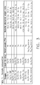
- Table 1 is shown which includes samples of compositions for metal structure 56.
- gallium alloys are formed with combining gallium with one or both of tin and indium. These metal alloys are initially in a liquid state at about room temperature below thirty degrees Centigrade (30° C). The liquid metal alloy containing gallium is then mixed with a solid metal or solid metal alloy. The solid metal or solid metal alloy to be mixed with the liquid metal alloy is either in a powder or film state. The dimension of the particle size or the film thicknesses are between fifty nanometers (50 nm) and one hundred micro meters (100 ⁇ m). As can be seen in Table 1 of FIG. 3 , the solid metal mixed with the gallium alloy are either pure nickel, pure copper or pure silver. A solid metal alloy, of bronze, can selectively be used to mix with the liquid gallium metal alloy. Table 1 shows the material elemental weight ratio of the chemical components to be mixed to create each sample of metal structure 56.
- the resulting slurry or paste-like consistency provides the user the ability to properly apply the material to conform to the roughened surfaces of the fastener and the composite material.
- the material or metal structure 56 cures into a solid state.
- the assembled structure, or in this example, aircraft 10, can then be used for flight.
- An additional mechanical reinforcing phase can be added to the slurry of the mixture of the liquid gallium metal alloy with a solid metal or solid metal alloy.
- This mechanical phase will provide enhanced shear resistance to the cured solidified alloy.
- This mechanical phase material can selectively include one of a pure cobalt, pure tungsten, pure molybdenum or pure titanium or of an alloy of titanium, such as AMS 4911, or stainless steel, such as 302 or 316.
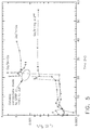
- the graph shows free corrosion test results of five select samples of metal structure 56 which appear in Table 1 of FIG. 3 . Corrosion resistance is important for metal structure 56, which will perform in the outside environment exposed to varying environmental conditions.
- the testing criteria assessment uses a commercial 3-electrode corrosion test cell. In addition to the tested samples, which comprised the working electrode, the cell contained a platinum mesh counter electrode and a silver wire reference electrode. The electrolyte (the corrosive environment) was three per cent by weight (3.0 wt%) Sodium Chloride (NaCl) solution exposed to laboratory air, i.e. containing dissolved oxygen.
- NaCl Sodium Chloride
- Free corrosion rates are given by the inverse of the polarization resistance are shown in this graph in FIG. 4 .
- the lower the inverse polarization resistance values on this graph indicates a greater resistance to corrosion.
- All of the copper containing metal alloys had equivalent corrosion rates regardless of the composition of the metal when the same liquid metal alloy (Ga/In or Ga/In/Sn) was used.
- the gallium liquid metal alloy had some effect.
- the gallium/tin liquid metal alloy was more corrosion resistant than gallium/indium liquid metals. The difference is attributable to tin being more oxidatively stable than indium.
- the silver containing solidified metals were more stable than any indium containing material.
- this graph shows galvanic corrosion testing results for three selected samples of metal structure 56 from Table 1 of Fig. 3 . Galvanic testing is conducted on samples of metal structure 56 since metal structure 56 is in constant electrical contact with conductive carbon fiber of the composite material.
- the testing criteria includes placing each sample in contact with carbon fiber reinforced plastic ("CFRP") and using linear polarization measurements performed on combined test sample/CFRP electrodes.
- CFRP carbon fiber reinforced plastic
- This approach treats the galvanic couple as a single electrode and enables a relative comparison of the free corrosion and galvanic corrosion rates.
- the CFRP was prepared by cutting a one square centimeter piece (1 cm 2 ) from a CFRP panel. One face was ground to expose the carbon fiber. The edges and back were sealed with 5 minute epoxy cured overnight at fifty degrees Centigrade (50° C). The entire CRFP piece was immersed in the electrolyte adjacent to the test sample. Electrical connection between the test sample and the CFRP was made using a jumper from the test sample to an epoxy sealed threaded rod connected to the CFRP.
- the area for the test samples was 0.785 square centimeters (0.785 cm 2 ) and the area of the CFRP was two centimeters by two centimeters (2 cm x 2 cm) which equals four square centimeters (4 cm 2 ).
- the area ratio of CFRP/metal alloy was 5:1.
- the initial eighteen to twenty two hours portrayed on the graph are free corrosion test results for these three samples.
- the above galvanic test was then initiated, which indicated a steep rise in the corrosion rates for each sample in this graph.
- the corrosion rate of each of the three samples substantially leveled and reached a steady state. Again, the higher position on this graph indicates a greater corrosion rate.
- the gallium/tin with copper alloy and the gallium/indium with copper alloy have similar corrosion rates.
- the gallium/indium and silver alloy had the lowest corrosion rate.
- Table 2 of corrosion rates of five samples are provided.
- the first three samples are sample compositions from Table 1 of FIG. 3 and are found in the corrosion tests in the graphs set forth in FIGS. 4 and 5 .
- the next sample in Table 2 is copper foil and the final sample is aluminum alloy 6061.
- This table shows in the first column the free corrosion rate. In the second column is shown the galvanic corrosion rate. In the third column, is shown a ratio of the galvanic corrosion rate in ratio to free corrosion rate.
- the gallium liquid alloy mixed with copper solid metal samples have slightly greater galvanic corrosion rates than copper foil and gallium liquid alloy mixed with silver solid metal, but significantly less corrosion rate than aluminum alloy 6061.
Landscapes
- Engineering & Computer Science (AREA)
- Mechanical Engineering (AREA)
- Chemical & Material Sciences (AREA)
- Composite Materials (AREA)
- Manufacturing & Machinery (AREA)
- Materials Engineering (AREA)
- Aviation & Aerospace Engineering (AREA)
- General Engineering & Computer Science (AREA)
- Laminated Bodies (AREA)
- Connection Of Plates (AREA)
- Manufacture Of Alloys Or Alloy Compounds (AREA)
Abstract
Description
- This invention relates to a gap filler positioned between structural components of a structure, and more particularly, the gap filler which provides electrical conductivity between the structural components of an aircraft.
- Structures and particularly aircraft are designed to withstand lightning strikes and maintain their structural integrity. Traditional construction of aircraft, for example, included metallic structural elements being secured together with metallic fasteners. The fasteners were electrically grounded to the metallic structural elements with the metallic fasteners being in contact with the metallic structural elements. This arrangement provided electrical conductivity between the fastener and the structural element thereby not electrically isolating the fastener from the structural elements. Isolating the fastener would otherwise provide an undesired electrostatic force between the fastener and the structural element upon the occurrence of a lightning strike to the aircraft.
- Aircraft are more recently being constructed of structural components made of a composite material. The composite material comprises a matrix material, often a resin, and of a fiber material such as carbon fiber. The resin is generally not as electrically conductive in contrast to the fiber material. This composite material is often carbon fiber reinforced plastic ("CFRP"). The CFRP structural elements are secured together with fasteners, such as, metallic bolts. A bolt used to fasten a structural element constructed of CFRP may not necessarily be electrically grounded to the CFRP structural element. Rough surfaces of the bolt and rough surfaces of the structural element can create gaps between the surface of the metallic bolt and that of the electrically conductive fiber. This condition can lead to an electrostatic force build up between the fastener and the structural element constructed of CFRP.
- Currently, in an attempt to prevent an electrostatic force build-up between the fastener and the structural element, the fasteners or bolts are coated with an electrically insulating sealant material before they are secured to the structural element constructed of CFRP material. Thus, at the time of a lightning strike to the aircraft, the insulating of the fastener from the structural element prevents an undesired electrostatic build-up between the fastener and the structural element.
- However, coating the fasteners with the sealant and then securing them to the structural element takes a great deal of care, time and expense compared to the traditional securement of metallic structural elements with metallic fasteners. The sealant must completely cover the surface of the fastener, otherwise, at the time of a lightning strike to the aircraft, current could travel from the fibers of the structural element to the fastener through an opening or breach of the sealant. Current that passes through such opening will charge the fastener and create an imbalance of the charge between the fastener and the fiber of the CFRP. This condition can create undesired electrostatic forces between the bolt and the fibers of the CFRP. Additional, care needs to be taken in securing the fastener such that sealant is not removed in the process. Furthermore, once the fastener is installed, careful inspection needs to be made that no opening through the sealant was created during the securement process of the fastener. Thus, careful steps must be taken in coating the fastener, securing the fastener and inspecting the fastener in the fastening process. These steps contribute to cost of the assembly the aircraft.
- Other attempts to prevent undesired electrostatic force build-up between the CFRP material of the structural element and the metallic fastener or bolt have been attempted. These attempts were not feasible. For example, the use of a metallic solder could not be employed. Even though solder would provide electrical conductivity and structural integrity between the bolt and the CFRP material, the integrity of the CFRP material is structurally compromised at a temperature of over two hundred and fifty four degrees Fahrenheit (254° F), which is below the melting temperature of many solders. Alternatively, a conductive adhesive could be employed between the bolt and the CFRP material. However, the adhesive has a more resistive conductivity than a metallic bond. This resistivity could result in a charge build up between the two surfaces of the bolt and the CFRP material and result in an undesired electrostatic discharge.
- A soft metallic insert could also be employed and positioned between the two surfaces of the bolt and the CFRP material. However, this may improve electrical conductivity between the two surfaces but creates a structural weak point between the two surfaces and is limited in its ability to conform to the two surfaces. Alternatively, welding the bolt to the CFRP structural component is not feasible, where one surface, that of the CFRP structural component, is non-metallic.
- There is a need for an inexpensive and reliable gap filler that will conform to the rough surfaces of the fastener or bolt and the structural element constructed of CFRP. The gap filler will need to provide electrical conductivity between the fastener or bolt and fibers of the CFRP material to ground the fastener to the structural element constructed of CFRP material.
- An example of a structural assembly of an aircraft includes a structural element constructed of a composite material which includes a matrix material and a plurality of fibers positioned to extend through the matrix material in which at least a portion of the plurality of fibers are accessible from a surface of the structural element. A fastener secures the structural element to a structural component. A metal structure comprising gallium is positioned in contact with a surface of the fastener. The metal structure extends from the surface of the fastener and contacts at least a portion of the at least a portion of the plurality of fibers.
- An example of a method for assembling a structure which includes the step of providing a structural element constructed of a composite material which includes a matrix material and plurality of fibers positioned to extend through the matrix material wherein at least a portion of the plurality of fibers are accessible from a surface of the structural element. Another step includes mixing a liquid metal alloy comprising gallium with at least one of a solid metal or solid metal alloy forming a slurry. The method further includes the step of applying the slurry onto a surface of a fastener and onto at least a portion of the at least of the portion of the plurality of fibers. Another step of the method includes securing the structural element with the fastener to a structural component wherein the slurry is positioned in contact with the surface of the fastener and interconnects the surface of the fastener with the at least a portion of the at least a portion of the plurality of fibers.
- The features, functions, and advantages that have been discussed can be achieved independently in various embodiments or may be combined in yet other embodiments further details of which can be seen with reference to the following description and drawings.
-
-
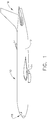
FIG. 1 is a side elevation view of an aircraft; -
FIG. 2 is an exemplary schematic fragmentary view of a selected portion of the aircraft inFIG. 1 , wherein a cross section is shown of a fastener connecting structural elements constructed of a composite material to a structural component with a metallic gap filler positioned in contact with and interconnecting a surface of the fastener with fibers of the composite material of the structural elements; -
FIG. 3 is Table 1 showing sample compositions of gap fillers comprising gallium based alloys of liquid metal combined with a pure solid metal or with a solid metal alloy; -
FIG. 4 is a graph showing free corrosion rates for selective samples of metallic gap fillers from Table 1 ofFIG. 3 ; -
FIG. 5 is a graph showing galvanic corrosion rates for selective samples of metallic gap fillers from Table 1 ofFIG. 3 ; and -
FIG. 6 is a Table 2 showing free and galvanic corrosion rates, along with relative galvanic to free corrosion rates for selective samples of metallic gap fillers from Table 1 along with copper foil andaluminum 6061 alloy. - While various embodiments have been described above, this disclosure is not intended to be limited thereto. Variations can be made to the disclosed embodiments that are still within the scope of the appended claims.
- As earlier discussed, it is important to assemble structures that resist damage when struck by lightning. An example of such assembled structures include aircraft. It is desired that electrostatic force build up is not created between metal fasteners and structural elements of the assembled aircraft at the time of a lightning strike. With aircraft being now selectively assembled with composite materials the grounding of a metal fastener with conductive fibers of the composite material of a structural element is needed.
- Referring to
FIG. 1 , an example of an assembled structure,aircraft 10 is shown.Aircraft 10 includes various sections to its assembly. These sections, in this example, include afuselage 12 andwings 14 extending from opposing sides offuselage 12.Fuselage 12 also includes anose section 16 and an opposingtail section 18. Each of these sections ofaircraft 10 can be selectively constructed with structural elements constructed of composite materials. - In referring to
FIG. 2 , an exemplary securement ofstructural element 20 is shown for an assembly of a selective section ofaircraft 10.Structural element 20 is constructed of a composite material, which includes amatrix material 22 and a plurality offibers 24 positioned to extend through thematrix material 22. - In this example shown in
FIG. 2 ,structural element 20 overlies anotherstructural element 26, which is also constructed of the composite material including amatrix material 28 and a plurality offibers 30 which are also positioned to extend throughmatrix material 28. Bothstructural element 20 and otherstructural element 26 are secured, tostructural component 32.Structural component 32 is another structural item of an assembly of a section ofaircraft 10.Structural component 32 can be constructed of a composite material, metal or the like. In this example,structural component 32 is a portion of a metallic frame positioned within a select section ofaircraft 10. - Plurality of
fibers Matrix material -
Structural element 20 and anotherstructural element 26 are secured tostructural component 32 withfastener 34.Fastener 34 is a securement item, which can secure two or more items together, such as a bolt, screw, pin or the like. In this example,fastener 34 is a bolt, which includeshead 36, threaded shaft 38 (threads not shown) and threaded nut 40 (threads not shown). Fastener orbolt 34 is constructed of metal, such as carbon steel, titanium alloy or the like. - In this example, through-
hole 42 is positioned throughstructural component 32. Through-hole, in this example, was pre-formed instructural component 32. Through-hole 42 may also be positioned throughstructural component 32 by drilling throughstructural component 32. Through-hole 44 andrecess section 54 ofstructural element 20 and through-hole 46 of otherstructural element 26 have been formed with drilling throughstructural element 20 and otherstructural element 26, in this example. In drilling through composite material ofstructural element 20 and anotherstructural element 26,rough surface 48 ofstructural element 20 andrough surface 50 of otherstructural element 26 are formed. Additionally,rough surface 52 is formed inrecess section 54 ofstructural element 20. - Plurality of
fibers 24, which extend throughmatrix material 22 ofstructural element 20 are schematically represented, inFIG. 2 . In this example, plurality offibers 24 extend throughmatrix material 22 and are positioned throughoutstructural element 20, extending in the length direction, width direction and layered in the thickness direction ofstructural element 20. Plurality offibers 24 inFIG. 2 are schematically shown extending in a length direction and layered in the thickness direction ofstructural element 20 without showing plurality offibers 24 extending in a width direction withinmatrix 22. - With the formation of a discrete through-
hole 44 andrecess section 54 throughstructural element 20, through-hole 44 andrecess section 54 engages at least aportion 25 of the total of the plurality offibers 24, which are positioned throughoutstructural element 20. InFIG. 2 the at least aportion 25 of the plurality offibers 24 ofstructural element 20 are schematically shown positioned at and alongrough surface 48 of through-hole 44 and at and alongrough surface 52 ofrecess section 54.Portion 25 of plurality offibers 24, are also positioned about through-hole 44 andrecess section 54, but are not shown. The at least aportion 25 of plurality offibers 24, inFIG. 2 , are shown schematically extending torough surface 48 at through-hole 44 and torough surface 52 atrecess section 54. However, with through-hole 44 andrecess section 54 formed, in this example, by drilling throughstructural element 20, ends of the at least aportion 25 of the plurality offibers 24 positioned at through-hole 44 andrecess section 54 may extend from, be flush with or be recessed fromrough surface 48 andrough surface 52. Regardless of the position of an end of a fiber of the at least aportion 25 of plurality offibers 24 relative torough surfaces rough surface 48 in through-hole 44 and fromrough surface 52 ofrecess section 54. - Other
structural element 26 with plurality offibers 30 are similarly configured and schematically presented as described above forstructural element 20 with plurality offibers 24. Plurality offibers 30 are schematically shown to extend throughmatrix material 28 and are positioned throughout anotherstructural element 26, extending in the length direction, width direction and layered in the thickness direction of anotherstructural element 26 as the plurality offibers 24 were configured withinstructural element 20 and schematically shown. Plurality offibers 30, in this example, are shown extending in a length direction and layered in the thickness direction of anotherstructural element 26 without showing plurality offibers 24 extending in a width direction withinmatrix 28. - With the formation of a discrete through-
hole 46 throughstructural element 26, through-hole 46 engages at least aportion 47 of the total of the plurality offibers 30, which are positioned throughout anotherstructural element 26. The at least aportion 47 of the plurality offibers 30 ofstructural element 26 are schematically shown positioned at and alongrough surface 50 of through-hole 46. The at least aportion 47 of plurality offibers 30, are also positioned about through-hole 46 but are not shown. The at least aportion 47 of plurality offibers 30 are shown schematically extending torough surface 50 at through-hole 46. However, with through-hole 46 formed, in this example, by drilling throughstructural element 26, ends of the at least aportion 47 of the plurality offibers 30 positioned at through-hole 46 may extend from, be flush with or be recessed fromrough surface 50. Regardless of the position of an end of a fiber of the at least aportion 47 of plurality offibers 30 relative torough surface 50, the ends will be accessible fromrough surface 50 in through-hole 46. - In forming recessed
portion 54 and through-hole 44 ofstructural element 20 and forming through-hole 46 of otherstructural element 26, these openings are dimensioned to be slightly larger thanfastener 34 to enablefastener 34 to extend throughstructural element 20 and anotherstructural element 26. For the same reason, through-hole 42 ofstructural component 32 is similarly slightly larger than the dimension offastener 34. Agap 55 is formed betweenhead 36 and threadedshaft 38, on the one hand, andrough surfaces structural element 20,recess portion 54 ofstructural element 20 and anotherstructural element 26, on the other hand.Gap 55 is also formed betweenstructural component 32 and fastener orbolt 34, as seen inFIG. 2 . - A
metal structure 56 is positioned within and conforms to the shape ofgap 55. Metal is a solid material that is typically malleable, fusible, and ductile, with good electrical and thermal conductivity.Metal structure 56 is in contact withsurface 57 offastener 34, which includessurface 58 ofhead 36 andsurface 60 of threadedshaft 38.Metal structure 56 extends acrossgap 55 fromsurfaces portion 25 of plurality offibers 24 associated withstructural element 20 andrecess section 54 ofstructural element 20. This configuration ofmetal structure 56 establishes an electrical connection with the fibers andfastener 34, thereby groundingfastener 34. Similarly,metal structure 56 contacts surface 57 offastener 34, which includessurface 60 and extends acrossgap 55 and contacts at least a portion of the at least aportion 47 of plurality offibers 30 associated with anotherstructural element 26. Likewise, this configuration ofmetal structure 56 establishes an electrical connection with the fibers andfastener 34, thereby groundingfastener 34. Also, in this example,metal structure 56 contacts surface 57 offastener 34, which includessurface 60 and extends acrossgap 55 and contacts surface 62 ofstructural component 32 at through-hole 42. This configuration ofmetal structure 56 also establishes and electrical connection betweenfastener 34 andstructural component 32. -
Metal structure 56, as described above, extends from the above-described surfaces offastener 34 acrossgap 55 to the above described at least a portion of the at least aportion fibers structural component 32.Metal structure 56 extends in a range between twenty-five micrometers (25 µm) and one millimeter (1 mm) in accomplishing these electrical connections. In extending acrossgap 55,metal structure 56 comes into contact and conforms torough surfaces metal structure 56 is applied in a slurry or paste-like consistency to the above described surfaces offastener 34 and torough surfaces surface 62. In application of metal structure torough surfaces portion fibers metal structure 56. In securingstructural element 20 and otherstructural element 26 tostructural component 32 withfastener 34 the paste-like consistency ofmetal structure 56 is positioned within and occupiesgap 55 and provides a continuous electrical connection betweenfastener 34 and the above described fibers of the composite material. Metal structure also provides an electrical connection betweenfastener 34 andstructural component 32. - A method for assembling a structure, such as in this example,
aircraft 10, includes providingstructural element 20. In this example, otherstructural element 26 is additionally provided.Structural element 20 as is otherstructural element 26 are constructed of a composite material which includes , as described earlier, amatrix material 22 forstructural element 20 andmatrix material 28 for otherstructural element 26. A plurality offibers 24 extend throughmatrix material 22 ofstructural element 20 and plurality offibers 30 extend throughmatrix material 28. At least aportion 25 of the plurality offibers 24, as described above, are accessible fromrough surfaces structural element 20 and at least aportion 47 of plurality offibers 30 , as described above, are accessible fromrough surface 50 associated withstructural element 26. Withstructural element 20, otherstructural element 26,structural component 32 andfastener 34 available to assemble, mixing a liquid metal alloy containing gallium with at least one of a solid metal and solid metal alloy can be conducted. In this example, a Wig-L-Bug dental amalgamator is employed. This mixture forms a slurry. - The slurry or paste-like mixture is applied to surface 57, including
surfaces fastener 34 and onto at least a portion of the at least aportion fibers rough surfaces structural component 32. With the paste-like material ofmetal structure 56 properly applied, securingstructural element 20, along with in this embodiment, otherstructural element 26, tostructural component 32 withfastener 34 can proceed, as described above. With securing fastener orbolt 34,gap 55 becomes occupied and filled with the paste-like consistency ofmetal structure 56 and conforms to the shape ofgap 55. As will be described below, the paste-like material over a period of time sets and solidifies.Metal structure 56 provides the needed electrical connection betweenfastener 34 and the fibers and thestructural component 32 andgrounds fastener 34. -
Metal structure 56, which contains a gallium alloy, is initially in a liquid state at approximately room temperature and is then mixed with a metal powder or film to form a slurry, wherein a peritectic bond formed in which gallium within the liquid metal alloy diffuses into a solid metal such as a pure metal or metal alloy. The initial mixture forms a slurry or paste-like mixture that transforms into an alloy with a higher melting temperature. Over time, the slurry or paste-like consistency cures into a solid. - Referring to
FIG, 3 , Table 1 is shown which includes samples of compositions formetal structure 56. As can be seen in Table 1, gallium alloys are formed with combining gallium with one or both of tin and indium. These metal alloys are initially in a liquid state at about room temperature below thirty degrees Centigrade (30° C). The liquid metal alloy containing gallium is then mixed with a solid metal or solid metal alloy. The solid metal or solid metal alloy to be mixed with the liquid metal alloy is either in a powder or film state. The dimension of the particle size or the film thicknesses are between fifty nanometers (50 nm) and one hundred micro meters (100 µm). As can be seen in Table 1 ofFIG. 3 , the solid metal mixed with the gallium alloy are either pure nickel, pure copper or pure silver. A solid metal alloy, of bronze, can selectively be used to mix with the liquid gallium metal alloy. Table 1 shows the material elemental weight ratio of the chemical components to be mixed to create each sample ofmetal structure 56. - With the mixing of the gallium alloy with the solid metal or solid metal alloy, the resulting slurry or paste-like consistency provides the user the ability to properly apply the material to conform to the roughened surfaces of the fastener and the composite material. Once securement is completed using
fastener 34, the material ormetal structure 56 cures into a solid state. The assembled structure, or in this example,aircraft 10, can then be used for flight. - An additional mechanical reinforcing phase can be added to the slurry of the mixture of the liquid gallium metal alloy with a solid metal or solid metal alloy. This mechanical phase will provide enhanced shear resistance to the cured solidified alloy. This mechanical phase material can selectively include one of a pure cobalt, pure tungsten, pure molybdenum or pure titanium or of an alloy of titanium, such as AMS 4911, or stainless steel, such as 302 or 316.
- Referring now to
FIG. 4 , the graph shows free corrosion test results of five select samples ofmetal structure 56 which appear in Table 1 ofFIG. 3 . Corrosion resistance is important formetal structure 56, which will perform in the outside environment exposed to varying environmental conditions. The testing criteria assessment uses a commercial 3-electrode corrosion test cell. In addition to the tested samples, which comprised the working electrode, the cell contained a platinum mesh counter electrode and a silver wire reference electrode. The electrolyte (the corrosive environment) was three per cent by weight (3.0 wt%) Sodium Chloride (NaCl) solution exposed to laboratory air, i.e. containing dissolved oxygen. Using the fixturing in the cell, a surface area of one square centimeter (1cm x 1 cm) of each sample was exposed to the electrolyte. Standard linear polarization measurements were performed around the (open circuit) corrosion potential using -10 mV to +10mV potential sweeps. The data was fit to straight lines to obtain the polarization resistance (Rp, Ohms). Relative corrosion rates were expressed using the inverse of the polarization resistance. As can be seen in the graph, the testing in at least one instance extended to eighty hours. - Free corrosion rates are given by the inverse of the polarization resistance are shown in this graph in
FIG. 4 . The lower the inverse polarization resistance values on this graph indicates a greater resistance to corrosion. All of the copper containing metal alloys had equivalent corrosion rates regardless of the composition of the metal when the same liquid metal alloy (Ga/In or Ga/In/Sn) was used. The gallium liquid metal alloy had some effect. The gallium/tin liquid metal alloy was more corrosion resistant than gallium/indium liquid metals. The difference is attributable to tin being more oxidatively stable than indium. As can be noted, the silver containing solidified metals were more stable than any indium containing material. - Referring to
FIG. 5 , this graph shows galvanic corrosion testing results for three selected samples ofmetal structure 56 from Table 1 ofFig. 3 . Galvanic testing is conducted on samples ofmetal structure 56 sincemetal structure 56 is in constant electrical contact with conductive carbon fiber of the composite material. - The testing criteria includes placing each sample in contact with carbon fiber reinforced plastic ("CFRP") and using linear polarization measurements performed on combined test sample/CFRP electrodes. This approach treats the galvanic couple as a single electrode and enables a relative comparison of the free corrosion and galvanic corrosion rates. The CFRP was prepared by cutting a one square centimeter piece (1 cm2) from a CFRP panel. One face was ground to expose the carbon fiber. The edges and back were sealed with 5 minute epoxy cured overnight at fifty degrees Centigrade (50° C). The entire CRFP piece was immersed in the electrolyte adjacent to the test sample. Electrical connection between the test sample and the CFRP was made using a jumper from the test sample to an epoxy sealed threaded rod connected to the CFRP. The area for the test samples was 0.785 square centimeters (0.785 cm2) and the area of the CFRP was two centimeters by two centimeters (2 cm x 2 cm) which equals four square centimeters (4 cm2). Thus, the area ratio of CFRP/metal alloy was 5:1.
- In referring to the graph in
FIG. 5 , the initial eighteen to twenty two hours portrayed on the graph are free corrosion test results for these three samples. The above galvanic test was then initiated, which indicated a steep rise in the corrosion rates for each sample in this graph. As time progressed, the corrosion rate of each of the three samples substantially leveled and reached a steady state. Again, the higher position on this graph indicates a greater corrosion rate. As can be seen, the gallium/tin with copper alloy and the gallium/indium with copper alloy have similar corrosion rates. The gallium/indium and silver alloy had the lowest corrosion rate. - In referring to
FIG. 6 , Table 2 of corrosion rates of five samples are provided. The first three samples are sample compositions from Table 1 ofFIG. 3 and are found in the corrosion tests in the graphs set forth inFIGS. 4 and5 . The next sample in Table 2 is copper foil and the final sample isaluminum alloy 6061. This table shows in the first column the free corrosion rate. In the second column is shown the galvanic corrosion rate. In the third column, is shown a ratio of the galvanic corrosion rate in ratio to free corrosion rate. The gallium liquid alloy mixed with copper solid metal samples have slightly greater galvanic corrosion rates than copper foil and gallium liquid alloy mixed with silver solid metal, but significantly less corrosion rate thanaluminum alloy 6061. - Further, the disclosure comprises embodiments according to the following clauses:
- Clause 1: A structural assembly of an aircraft, comprising: a structural element constructed of a composite material comprising a matrix material and a plurality of fibers positioned to extend through the matrix material, wherein at least a portion of the plurality of fibers are accessible from a surface of the structural element; a fastener secures the structural element to a structural component; and a metal structure positioned in contact with a surface of the fastener, wherein the metal structure extends from the surface of the fastener and contacts at least a portion of the at least a portion of the plurality of fibers.
- Clause 2: The structural assembly of
clause 1, wherein: the plurality of fibers comprises carbon; the matrix material comprises one of a thermoplastic resin and thermosetting resin; and the fastener is constructed of a metal. - Clause 3: The structural assembly of
clause 1, wherein the metal structure comprises a gallium alloy comprising at least one of indium and tin. - Clause 4: The structural assembly of
clause 1, wherein the metal structure further comprises one of a solid metal and a solid metal alloy. - Clause 5: The structural assembly of
clause 4, wherein: the one of the solid metal and the solid metal alloy comprises one of a powder and a film; and a particle size of the powder or a thickness of the film has a dimension in a range between 50 nm and 100 µm. - Clause 6: The structural assembly of
clause 5, wherein the solid metal comprises one of pure copper, pure silver, and pure nickel. - Clause 7: The structural assembly of
clause 5, wherein the solid metal alloy comprises bronze. - Clause 8: The structural assembly of
clause 1, wherein the metal structure further comprises a mechanical reinforcing phase comprising one of pure cobalt, pure tungsten, pure molybdenum, and pure titanium or an alloy comprising one of a titanium alloy and a stainless steel. - Clause 9: The structural assembly of
clause 1, wherein: the metal structure extends in a range between 25 µm and 1 mm between the surface of the fastener to at least a portion of the portion of the plurality of fibers; and the metal structure is in contact with the surface of the structural element. - Clause 10: A method for assembling a structure, comprising the steps of: providing a structural element constructed of a composite material comprising a matrix material and a plurality of fibers positioned to extend through the matrix material, wherein at least a portion of the plurality of fibers are accessible from a surface of the structural element; mixing a liquid metal alloy comprising gallium with at least one of a solid metal and solid metal alloy forming a slurry; applying the slurry onto a surface of a fastener and onto at least a portion of the at least a portion of the plurality of fibers; and securing the structural element with the fastener to a structural component wherein the slurry is positioned in contact with the surface of the fastener and interconnects the surface of the fastener with the at least a portion of the at least a portion of the plurality of fibers.
- Clause 11: The method for assembling a structure of
clause 10, wherein: the plurality of fibers comprises carbon; the matrix material comprises one of a thermoplastic resin and thermosetting resin; the fastener is constructed of a metal; and the step of securing includes placing the slurry in contact with the surface of the structural element. - Clause 12: The method for assembling a structure of
clause 10, wherein: the liquid metal is an alloy comprising at least one of indium and tin; and the step of mixing includes mixing the liquid metal alloy with at least one of a solid metal and a solid metal alloy. - Clause 13: The method for assembling a structure of
clause 12, wherein the one of the solid metal and the solid metal alloy comprises one of a powder and a film. - Clause 14: The method for assembling a structure of clause 13 wherein a particle size of the powder or a thickness of the film has a dimension in a range between 50 nm and 100 µm.
- Clause 15: The method for assembling a structure of
clause 12, wherein the solid metal comprises at least one of pure copper, pure silver and pure nickel. - Clause 16: The method for assembling a structure of
clause 12, wherein the solid metal alloy comprises an alloy of bronze. - Clause 17: The method for assembling a structure of
clause 10 wherein the step of mixing further includes mixing a mechanical reinforcing phase comprising one of pure cobalt, pure tungsten, pure molybdenum and pure titanium or an alloy comprising one of a titanium alloy and stainless steel. - Clause 18: The method for assembling a structure of
clause 10 wherein the liquid metal has a melting temperature of below thirty degrees Centigrade (30° C). - Clause 19: The method for assembling an aircraft of
clause 10 further including the step of allowing the slurry to solidify prior to placing the aircraft into flight. - Clause 20: The method for assembling a structure of
clause 10, wherein the structural element and the structural component are parts of an aircraft. - While various embodiments have been described above, this disclosure is not intended to be limited thereto. Variations can be made to the disclosed embodiments that are still within the scope of the appended claims.
Claims (15)
- A structural assembly (14) of an aircraft (10), comprising:a structural element (20, 26) constructed of a composite material comprising a matrix material (22, 28) and a plurality of fibers (24, 30) positioned to extend through the matrix material, wherein at least a portion of the plurality of fibers are accessible from a surface (48, 50, 52) of the structural element;a fastener (34) secures the structural element to a structural component (32); anda metal structure (56) positioned in contact with a surface (38) of the fastener, wherein the metal structure extends from the surface of the fastener and contacts at least a portion (25) of the at least a portion of the plurality of fibers.
- The structural assembly of claim 1,
wherein: the plurality of fibers
comprises carbon;
the matrix material comprises one of a thermoplastic resin and thermosetting resin; and
the fastener is constructed of a metal. - The structural assembly of any of claims 1-2, wherein the metal structure comprises a gallium alloy comprising at least one of indium and tin.
- The structural assembly of any of claims 1-3, wherein the metal structure further comprises one of a solid metal and a solid metal alloy.
- The structural assembly of claim 4, wherein:the one of the solid metal and the solid metal alloy comprises one of a powder and a film; anda particle size of the powder or a thickness of the film has a dimension in a range between 50 nm and 100 µm.
- The structural assembly of claim 5, wherein the solid metal comprises one of pure copper, pure silver, and pure nickel.
- The structural assembly of any of claims 5-6, wherein the solid metal alloy comprises bronze.
- The structural assembly of any of claims 1-4, wherein the metal structure further comprises a mechanical reinforcing phase comprising one of pure cobalt, pure tungsten, pure molybdenum, and pure titanium or an alloy comprising one of a titanium alloy and a stainless steel.
- The structural assembly of any of claims 1-4 or 8, wherein:the metal structure extends in a range between 25 µm and 1 mm between the surface of the fastener to at least a portion of the portion of the plurality of fibers; andthe metal structure is in contact with the surface of the structural element.
- A method for assembling a structure (10), comprising the steps of:providing a structural element (20, 26) constructed of a composite material comprising a matrix material (22, 28) and a plurality of fibers (24, 30) positioned to extend through the matrix material, wherein at least a portion of the plurality of fibers are accessible from a surface (48, 50, 52) of the structural element;mixing a liquid metal alloy comprising gallium with at least one of a solid metal and solid metal alloy forming a slurry (56);applying the slurry onto a surface (38) of a fastener (34) and onto at least a portion (25) of the at least a portion of the plurality of fibers; andsecuring the structural element with the fastener to a structural component (32) wherein the slurry is positioned in contact with the surface of the fastener and interconnects the surface of the fastener with the at least a portion of the at least a portion of the plurality of fibers.
- The method for assembling a structure of claim 10, wherein:the plurality of fibers comprises carbon;the matrix material comprises one of a thermoplastic resin and thermosetting resin;the fastener is constructed of a metal; andthe step of securing includes placing the slurry in contact with the surface of the structural element.
- The method for assembling a structure of any of claims 10-11, wherein:the liquid metal is an alloy comprising at least one of indium and tin; andthe step of mixing includes mixing the liquid metal alloy with at least one of a solid metal and a solid metal alloy.
- The method for assembling a structure of claim 12, wherein the one of the solid metal and the solid metal alloy comprises one of a powder and a film.
- The method for assembling an aircraft of any of claims 10-12 further including the step of allowing the slurry to solidify prior to placing the aircraft into flight.
- The method for assembling a structure of any of claims 10-12 or 14, wherein the structural element and the structural component are parts of an aircraft.
Applications Claiming Priority (1)
| Application Number | Priority Date | Filing Date | Title |
|---|---|---|---|
| US14/614,656 US20160229552A1 (en) | 2015-02-05 | 2015-02-05 | Intermetallic and composite metallic gap filler |
Publications (2)
| Publication Number | Publication Date |
|---|---|
| EP3053679A1 true EP3053679A1 (en) | 2016-08-10 |
| EP3053679B1 EP3053679B1 (en) | 2019-12-18 |
Family
ID=55637132
Family Applications (1)
| Application Number | Title | Priority Date | Filing Date |
|---|---|---|---|
| EP16153588.5A Active EP3053679B1 (en) | 2015-02-05 | 2016-02-01 | Intermetallic and composite metallic gap filler |
Country Status (6)
| Country | Link |
|---|---|
| US (1) | US20160229552A1 (en) |
| EP (1) | EP3053679B1 (en) |
| JP (1) | JP6719218B2 (en) |
| CN (2) | CN105857629A (en) |
| BR (1) | BR102015031874B1 (en) |
| CA (1) | CA2913166C (en) |
Cited By (3)
| Publication number | Priority date | Publication date | Assignee | Title |
|---|---|---|---|---|
| WO2018172719A1 (en) * | 2017-03-23 | 2018-09-27 | Centre Technique Des Industries Mecaniques | Thermoforming process and assembly |
| EP3473355A1 (en) * | 2017-10-18 | 2019-04-24 | The Boeing Company | Apparatus and methods for injecting filler material into a hole in a composite layer |
| US11498160B2 (en) * | 2017-03-10 | 2022-11-15 | Bayerische Motoren Werke Aktiengesellschaft | Bolt for fastening components, or the ground connection of electrical or electronic components, on a vehicle body, a bolt arrangement having a bolt, and a method for forming the bolt arrangement |
Families Citing this family (21)
| Publication number | Priority date | Publication date | Assignee | Title |
|---|---|---|---|---|
| EP2832645B1 (en) | 2012-03-26 | 2023-03-08 | Mitsubishi Heavy Industries, Ltd. | Fuel tank, main wing, aircraft fuselage, aircraft, and mobile body |
| BR112015006133A2 (en) * | 2012-10-09 | 2019-11-19 | Mitsubishi Heavy Ind Ltd | The structure material for structures, a fuel tank, a wing, and an airplane |
| JP6071686B2 (en) | 2013-03-26 | 2017-02-01 | 三菱重工業株式会社 | Fuel tank, main wing, aircraft fuselage, aircraft and mobile |
| US10640232B2 (en) * | 2016-12-20 | 2020-05-05 | The Boeing Company | Conductive fastening system for composite structures |
| US10518483B2 (en) * | 2017-01-25 | 2019-12-31 | The Boeing Company | Compound shimming |
| US20180339788A1 (en) * | 2017-05-26 | 2018-11-29 | Joe A. Garcia | Protective cap and nut gauge for an aircraft fuel tank fastener system |
| US20190032218A1 (en) * | 2017-07-28 | 2019-01-31 | The Boeing Company | Process for Adhering Solid Lubricant to Surface of Interference Fit Fastener |
| JP6778221B2 (en) * | 2018-01-15 | 2020-10-28 | 株式会社Subaru | Fastening structure |
| JP6770987B2 (en) * | 2018-03-12 | 2020-10-21 | 株式会社Subaru | Composite structure, aircraft and lightning current induction method |
| US10982705B2 (en) * | 2018-03-16 | 2021-04-20 | The Boeing Company | Method, apparatus and applicator for applying a coating on a surface of a lamination |
| US10739389B2 (en) | 2018-03-16 | 2020-08-11 | The Boeing Company | Systems and methods for measuring the electrical contact resistance at an interface |
| JP6985192B2 (en) | 2018-03-19 | 2021-12-22 | 三菱重工業株式会社 | Composite assembly |
| US11137014B2 (en) | 2019-01-08 | 2021-10-05 | The Boeing Company | Conductive fastening system and method for improved EME performance |
| US11181137B2 (en) * | 2019-05-20 | 2021-11-23 | The Boeing Company | Fastener systems and assemblies for coupling a part to a composite structure, and related methods |
| US11303047B2 (en) * | 2020-01-07 | 2022-04-12 | The Boeing Company | Conductively coated fastening systems for full size determinant assembly (FSDA) |
| US11879488B2 (en) | 2020-01-13 | 2024-01-23 | The Boeing Company | Lightning damage resistant one sided installation |
| US11685508B2 (en) * | 2020-04-08 | 2023-06-27 | The Boeing Company | Systems and methods for constructing a bonded structure |
| JP2023073774A (en) * | 2021-11-16 | 2023-05-26 | 三菱重工業株式会社 | Composite material structure, and method for producing composite material structure |
| US12070805B2 (en) | 2021-12-21 | 2024-08-27 | The Boeing Company | Drill spindle accessory for applying a material to an interior sidewall of a hole |
| JP2025002103A (en) * | 2023-06-21 | 2025-01-09 | 三菱重工業株式会社 | Thunder resistant structure of rocket, rocket including the same and method for manufacturing thunder resistant structure of rocket |
| EP4650156A1 (en) * | 2024-05-17 | 2025-11-19 | Airbus S.A.S. | Fibre composite material, a method of manufacturing a fibre composite ma-terial, a component consisting of or comprising a fibre composite material and a tank structure |
Citations (3)
| Publication number | Priority date | Publication date | Assignee | Title |
|---|---|---|---|---|
| US4755904A (en) * | 1986-06-06 | 1988-07-05 | The Boeing Company | Lightning protection system for conductive composite material structure |
| FR2765066A1 (en) * | 1997-06-20 | 1998-12-24 | Aerospatiale | ANTI-SPARK STRUCTURE, ESPECIALLY FOR AIRCRAFT |
| US20130099490A1 (en) * | 2011-10-24 | 2013-04-25 | The Boeing Company | Conductance on hydraulic fittings using a soft metal interlayer |
Family Cites Families (42)
| Publication number | Priority date | Publication date | Assignee | Title |
|---|---|---|---|---|
| US3755713A (en) * | 1972-07-25 | 1973-08-28 | Boeing Co | Electrically conductive surface for aircraft |
| US4479163A (en) * | 1982-09-30 | 1984-10-23 | The Boeing Company | Integral lightning protection system for composite aircraft skins |
| US4502092A (en) * | 1982-09-30 | 1985-02-26 | The Boeing Company | Integral lightning protection system for composite aircraft skins |
| US4542056A (en) * | 1983-08-26 | 1985-09-17 | The Boeing Company | Composite structure having conductive surfaces |
| GB8628555D0 (en) * | 1986-11-28 | 1987-01-07 | British Aerospace | Anti lightning strike fasteners |
| US4920449A (en) * | 1988-01-19 | 1990-04-24 | The Boeing Company | Conductive bonding of composite structures |
| US4905931A (en) * | 1988-02-18 | 1990-03-06 | The Boeing Company | Arc suppression around fasteners |
| US5225157A (en) * | 1989-07-19 | 1993-07-06 | Microelectronics And Computer Technology Corporation | Amalgam composition for room temperature bonding |
| GB8924231D0 (en) * | 1989-10-27 | 1989-12-13 | British Aerospace | Carbon fibre composite structures |
| US5170930A (en) * | 1991-11-14 | 1992-12-15 | Microelectronics And Computer Technology Corporation | Liquid metal paste for thermal and electrical connections |
| US5445308A (en) * | 1993-03-29 | 1995-08-29 | Nelson; Richard D. | Thermally conductive connection with matrix material and randomly dispersed filler containing liquid metal |
| US5328087A (en) * | 1993-03-29 | 1994-07-12 | Microelectronics And Computer Technology Corporation | Thermally and electrically conductive adhesive material and method of bonding with same |
| FR2718706B1 (en) * | 1994-04-15 | 1996-06-14 | Aerospatiale | Anti-spark structure, especially for aircraft. |
| GB9411006D0 (en) * | 1994-06-02 | 1994-07-20 | British Aerospace | Method of fastening composite aircraft skins |
| US6027575A (en) * | 1997-10-27 | 2000-02-22 | Ford Motor Company | Metallic adhesive for forming electronic interconnects at low temperatures |
| US6327132B1 (en) * | 1998-06-10 | 2001-12-04 | Aerospatiale Matra | Spark resistant structure, in particular for aircraft |
| CN1408494A (en) * | 2002-08-28 | 2003-04-09 | 丁刚 | Composite material producing extruding-casting, permeating and sintering process and equipment |
| EP1628879B1 (en) * | 2003-05-30 | 2006-09-20 | BAE Systems PLC | Composite structure lightning protection |
| US7554785B2 (en) * | 2004-03-23 | 2009-06-30 | The Boeing Company | Lightning damage protection for composite aircraft |
| US7686905B2 (en) * | 2005-09-06 | 2010-03-30 | The Boeing Company | Copper grid repair technique for lightning strike protection |
| US7551656B2 (en) * | 2006-03-29 | 2009-06-23 | Lockheed Martin Coherent Technologies, Inc. | Low stress optics mount using thermally conductive liquid metal or gel |
| US7898785B2 (en) * | 2006-12-07 | 2011-03-01 | The Boeing Company | Lightning protection system for an aircraft composite structure |
| DE102007003276B4 (en) * | 2007-01-23 | 2013-11-28 | Airbus Operations Gmbh | Aerospace vehicle with a CFRP component and a metal component, wherein the CFRP component and the metal component are connected to each other via at least one connecting element with a connecting portion |
| JP2008197296A (en) * | 2007-02-13 | 2008-08-28 | Sony Corp | Electrowetting device and manufacturing method thereof |
| JP2008285115A (en) * | 2007-05-21 | 2008-11-27 | Mitsubishi Heavy Ind Ltd | Assembly for aircraft and its manufacturing method |
| US7966711B2 (en) * | 2007-08-14 | 2011-06-28 | The Boeing Company | Method and apparatus for fastening components using a composite two-piece fastening system |
| JP4719203B2 (en) * | 2007-09-28 | 2011-07-06 | 三菱重工業株式会社 | Lightning fastener |
| WO2009052325A1 (en) * | 2007-10-16 | 2009-04-23 | Fatigue Technology, Inc. | Expandable fastener assembly with deformed collar |
| US7721996B2 (en) * | 2007-11-13 | 2010-05-25 | The Boeing Company | Fabrication and installation of preformed dielectric inserts for lightning strike protection |
| FR2924686B1 (en) * | 2007-12-11 | 2010-05-14 | Airbus France | PARAFOUDRE AND AIRCRAFT SYSTEM COMPRISING SUCH A SYSTEM. |
| JP5055178B2 (en) * | 2008-03-24 | 2012-10-24 | 三菱重工業株式会社 | Aircraft assembly |
| US8834766B2 (en) * | 2008-07-31 | 2014-09-16 | Airbus Operations S.L. | Protection of elements in composite material |
| US8382413B2 (en) * | 2008-11-17 | 2013-02-26 | The Boeing Company | Conductive sleeved fastener assembly |
| US9984787B2 (en) * | 2009-11-11 | 2018-05-29 | Samsung Electronics Co., Ltd. | Conductive paste and solar cell |
| US20120019973A1 (en) * | 2010-06-14 | 2012-01-26 | Aurora Flight Sciences Corporation | Method and apparatus for grounding a composite aircraft structure |
| US8668847B2 (en) * | 2010-08-13 | 2014-03-11 | Samsung Electronics Co., Ltd. | Conductive paste and electronic device and solar cell including an electrode formed using the conductive paste |
| US8791375B2 (en) * | 2010-12-16 | 2014-07-29 | The Boeing Company | Electrically conductive bushing connection to structure for current path |
| JP5713980B2 (en) * | 2012-10-15 | 2015-05-07 | 三菱航空機株式会社 | Lightning-resistant fasteners and aircraft |
| EP2730508B1 (en) * | 2012-11-12 | 2016-09-14 | Airbus Operations GmbH | Lining/fairing panel and method for measuring the electrical bonding resistance of a lining/fairing panel |
| US9331402B2 (en) * | 2013-02-04 | 2016-05-03 | The Boeing Company | Conductive sleeved fastener assembly |
| US9343824B2 (en) * | 2013-02-04 | 2016-05-17 | The Boeing Company | Sleeved fastener assembly |
| US9682533B1 (en) * | 2014-09-09 | 2017-06-20 | Hrl Laboratories, Llc | Methods to form electrical-mechanical connections between two surfaces, and systems and compositions suitable for such methods |
-
2015
- 2015-02-05 US US14/614,656 patent/US20160229552A1/en not_active Abandoned
- 2015-11-24 CA CA2913166A patent/CA2913166C/en active Active
- 2015-12-18 BR BR102015031874-0A patent/BR102015031874B1/en active IP Right Grant
-
2016
- 2016-01-25 JP JP2016011801A patent/JP6719218B2/en active Active
- 2016-02-01 EP EP16153588.5A patent/EP3053679B1/en active Active
- 2016-02-04 CN CN201610078400.3A patent/CN105857629A/en active Pending
- 2016-02-04 CN CN202310333455.4A patent/CN116331503A/en active Pending
Patent Citations (3)
| Publication number | Priority date | Publication date | Assignee | Title |
|---|---|---|---|---|
| US4755904A (en) * | 1986-06-06 | 1988-07-05 | The Boeing Company | Lightning protection system for conductive composite material structure |
| FR2765066A1 (en) * | 1997-06-20 | 1998-12-24 | Aerospatiale | ANTI-SPARK STRUCTURE, ESPECIALLY FOR AIRCRAFT |
| US20130099490A1 (en) * | 2011-10-24 | 2013-04-25 | The Boeing Company | Conductance on hydraulic fittings using a soft metal interlayer |
Cited By (6)
| Publication number | Priority date | Publication date | Assignee | Title |
|---|---|---|---|---|
| US11498160B2 (en) * | 2017-03-10 | 2022-11-15 | Bayerische Motoren Werke Aktiengesellschaft | Bolt for fastening components, or the ground connection of electrical or electronic components, on a vehicle body, a bolt arrangement having a bolt, and a method for forming the bolt arrangement |
| WO2018172719A1 (en) * | 2017-03-23 | 2018-09-27 | Centre Technique Des Industries Mecaniques | Thermoforming process and assembly |
| FR3064206A1 (en) * | 2017-03-23 | 2018-09-28 | Centre Technique Des Industries Mecaniques | METHOD AND THERMOFORMING ASSEMBLY |
| EP3473355A1 (en) * | 2017-10-18 | 2019-04-24 | The Boeing Company | Apparatus and methods for injecting filler material into a hole in a composite layer |
| JP2019107694A (en) * | 2017-10-18 | 2019-07-04 | ザ・ボーイング・カンパニーThe Boeing Company | Apparatus and method of pouring filler into hole in composite layer background |
| US10603844B2 (en) | 2017-10-18 | 2020-03-31 | The Boeing Company | Apparatus and methods for injecting filler material into a hole in a composite layer |
Also Published As
| Publication number | Publication date |
|---|---|
| CA2913166A1 (en) | 2016-08-05 |
| CA2913166C (en) | 2020-10-27 |
| EP3053679B1 (en) | 2019-12-18 |
| BR102015031874B1 (en) | 2020-10-27 |
| JP6719218B2 (en) | 2020-07-08 |
| BR102015031874A2 (en) | 2017-01-24 |
| CN116331503A (en) | 2023-06-27 |
| CN105857629A (en) | 2016-08-17 |
| US20160229552A1 (en) | 2016-08-11 |
| JP2016175634A (en) | 2016-10-06 |
Similar Documents
| Publication | Publication Date | Title |
|---|---|---|
| EP3053679B1 (en) | Intermetallic and composite metallic gap filler | |
| US8322958B2 (en) | Fasteners with conforming sleeves | |
| DE68907396T2 (en) | Transfer means for continuous electrical conduction in fiber composite connections. | |
| DE60119270T2 (en) | CONDUCTIVE ADHESIVE, APPARATUS FOR MANUFACTURING AN ELECTRONIC COMPONENT AND METHOD FOR PRODUCTION THEREOF | |
| DE4341598B4 (en) | Composite particles, compositions containing them, processes for making same and uses | |
| DE60221079T3 (en) | Tin-silver coatings | |
| DE102012216461A1 (en) | Corrosion protection for magnesium components through a fastener insulation | |
| EP1730813A1 (en) | Method for joining a connecting element to an electric conductor made of aluminium and electric conductor produced according to said method | |
| EP2058081A2 (en) | Liquid metal paste | |
| DE102014117410B4 (en) | Electrical contact element, press-fit pin, socket and leadframe | |
| US20120019973A1 (en) | Method and apparatus for grounding a composite aircraft structure | |
| US10451099B2 (en) | Fasteners with conforming sleeves | |
| Yoo et al. | Influence of electrochemical properties on electrochemical migration of SnPb and SnBi solders | |
| Hua et al. | Electrochemical corrosion and electrochemical migration of 64Sn-35Bi-1Ag solder doping with xGe on printed circuit boards | |
| DE102009050319B4 (en) | Electrochemical device | |
| US20210180636A1 (en) | Mechanical fastener system for electromagnetic effect (eme) protection | |
| Sancaktar et al. | Conduction efficiency and strength of electronically conductive adhesive joints | |
| DE102011075926A1 (en) | Hybrid component and method for producing a hybrid component | |
| DE102010055949A1 (en) | Connecting assembly for two components, has adhesive joint, by which two components are connected with each other, where former component is made of metal, particularly aluminum-based alloy | |
| DE102018208116A1 (en) | Copper tape for making electrical contacts and method of making a copper tape and connectors | |
| EP3260377A1 (en) | Structural body production device and structural body production method | |
| DE10200564B4 (en) | Lightning protection device on fiber-reinforced components for removable cover with detachable bolt connections | |
| DE102016119491B3 (en) | Connecting part and method for producing a connection part | |
| Sabbar et al. | Evaluation of corrosion behaviour of a new class of Pb‐free solder materials (Sn‐In‐Zn) | |
| DE1209845B (en) | Anode arrangement for cathodic protection devices |
Legal Events
| Date | Code | Title | Description |
|---|---|---|---|
| PUAI | Public reference made under article 153(3) epc to a published international application that has entered the european phase |
Free format text: ORIGINAL CODE: 0009012 |
|
| 17P | Request for examination filed |
Effective date: 20160201 |
|
| AK | Designated contracting states |
Kind code of ref document: A1 Designated state(s): AL AT BE BG CH CY CZ DE DK EE ES FI FR GB GR HR HU IE IS IT LI LT LU LV MC MK MT NL NO PL PT RO RS SE SI SK SM TR |
|
| AX | Request for extension of the european patent |
Extension state: BA ME |
|
| STAA | Information on the status of an ep patent application or granted ep patent |
Free format text: STATUS: EXAMINATION IS IN PROGRESS |
|
| 17Q | First examination report despatched |
Effective date: 20180719 |
|
| RIC1 | Information provided on ipc code assigned before grant |
Ipc: B64D 37/32 20060101ALI20190523BHEP Ipc: B29C 70/88 20060101ALI20190523BHEP Ipc: C23F 13/00 20060101ALI20190523BHEP Ipc: F16B 1/00 20060101ALI20190523BHEP Ipc: B05D 7/00 20060101ALI20190523BHEP Ipc: B29L 31/30 20060101ALI20190523BHEP Ipc: B29C 65/00 20060101ALI20190523BHEP Ipc: B29C 65/56 20060101ALI20190523BHEP Ipc: B64D 45/02 20060101ALI20190523BHEP Ipc: B22F 7/06 20060101AFI20190523BHEP |
|
| GRAP | Despatch of communication of intention to grant a patent |
Free format text: ORIGINAL CODE: EPIDOSNIGR1 |
|
| STAA | Information on the status of an ep patent application or granted ep patent |
Free format text: STATUS: GRANT OF PATENT IS INTENDED |
|
| INTG | Intention to grant announced |
Effective date: 20190628 |
|
| GRAS | Grant fee paid |
Free format text: ORIGINAL CODE: EPIDOSNIGR3 |
|
| GRAA | (expected) grant |
Free format text: ORIGINAL CODE: 0009210 |
|
| STAA | Information on the status of an ep patent application or granted ep patent |
Free format text: STATUS: THE PATENT HAS BEEN GRANTED |
|
| AK | Designated contracting states |
Kind code of ref document: B1 Designated state(s): AL AT BE BG CH CY CZ DE DK EE ES FI FR GB GR HR HU IE IS IT LI LT LU LV MC MK MT NL NO PL PT RO RS SE SI SK SM TR |
|
| REG | Reference to a national code |
Ref country code: CH Ref legal event code: EP |
|
| REG | Reference to a national code |
Ref country code: IE Ref legal event code: FG4D |
|
| REG | Reference to a national code |
Ref country code: DE Ref legal event code: R096 Ref document number: 602016026216 Country of ref document: DE |
|
| REG | Reference to a national code |
Ref country code: AT Ref legal event code: REF Ref document number: 1214050 Country of ref document: AT Kind code of ref document: T Effective date: 20200115 |
|
| REG | Reference to a national code |
Ref country code: NL Ref legal event code: MP Effective date: 20191218 |
|
| PG25 | Lapsed in a contracting state [announced via postgrant information from national office to epo] |
Ref country code: LV Free format text: LAPSE BECAUSE OF FAILURE TO SUBMIT A TRANSLATION OF THE DESCRIPTION OR TO PAY THE FEE WITHIN THE PRESCRIBED TIME-LIMIT Effective date: 20191218 Ref country code: SE Free format text: LAPSE BECAUSE OF FAILURE TO SUBMIT A TRANSLATION OF THE DESCRIPTION OR TO PAY THE FEE WITHIN THE PRESCRIBED TIME-LIMIT Effective date: 20191218 Ref country code: BG Free format text: LAPSE BECAUSE OF FAILURE TO SUBMIT A TRANSLATION OF THE DESCRIPTION OR TO PAY THE FEE WITHIN THE PRESCRIBED TIME-LIMIT Effective date: 20200318 Ref country code: FI Free format text: LAPSE BECAUSE OF FAILURE TO SUBMIT A TRANSLATION OF THE DESCRIPTION OR TO PAY THE FEE WITHIN THE PRESCRIBED TIME-LIMIT Effective date: 20191218 Ref country code: GR Free format text: LAPSE BECAUSE OF FAILURE TO SUBMIT A TRANSLATION OF THE DESCRIPTION OR TO PAY THE FEE WITHIN THE PRESCRIBED TIME-LIMIT Effective date: 20200319 Ref country code: NO Free format text: LAPSE BECAUSE OF FAILURE TO SUBMIT A TRANSLATION OF THE DESCRIPTION OR TO PAY THE FEE WITHIN THE PRESCRIBED TIME-LIMIT Effective date: 20200318 Ref country code: LT Free format text: LAPSE BECAUSE OF FAILURE TO SUBMIT A TRANSLATION OF THE DESCRIPTION OR TO PAY THE FEE WITHIN THE PRESCRIBED TIME-LIMIT Effective date: 20191218 |
|
| REG | Reference to a national code |
Ref country code: LT Ref legal event code: MG4D |
|
| PG25 | Lapsed in a contracting state [announced via postgrant information from national office to epo] |
Ref country code: HR Free format text: LAPSE BECAUSE OF FAILURE TO SUBMIT A TRANSLATION OF THE DESCRIPTION OR TO PAY THE FEE WITHIN THE PRESCRIBED TIME-LIMIT Effective date: 20191218 Ref country code: RS Free format text: LAPSE BECAUSE OF FAILURE TO SUBMIT A TRANSLATION OF THE DESCRIPTION OR TO PAY THE FEE WITHIN THE PRESCRIBED TIME-LIMIT Effective date: 20191218 |
|
| PG25 | Lapsed in a contracting state [announced via postgrant information from national office to epo] |
Ref country code: AL Free format text: LAPSE BECAUSE OF FAILURE TO SUBMIT A TRANSLATION OF THE DESCRIPTION OR TO PAY THE FEE WITHIN THE PRESCRIBED TIME-LIMIT Effective date: 20191218 |
|
| PG25 | Lapsed in a contracting state [announced via postgrant information from national office to epo] |
Ref country code: RO Free format text: LAPSE BECAUSE OF FAILURE TO SUBMIT A TRANSLATION OF THE DESCRIPTION OR TO PAY THE FEE WITHIN THE PRESCRIBED TIME-LIMIT Effective date: 20191218 Ref country code: CZ Free format text: LAPSE BECAUSE OF FAILURE TO SUBMIT A TRANSLATION OF THE DESCRIPTION OR TO PAY THE FEE WITHIN THE PRESCRIBED TIME-LIMIT Effective date: 20191218 Ref country code: EE Free format text: LAPSE BECAUSE OF FAILURE TO SUBMIT A TRANSLATION OF THE DESCRIPTION OR TO PAY THE FEE WITHIN THE PRESCRIBED TIME-LIMIT Effective date: 20191218 Ref country code: PT Free format text: LAPSE BECAUSE OF FAILURE TO SUBMIT A TRANSLATION OF THE DESCRIPTION OR TO PAY THE FEE WITHIN THE PRESCRIBED TIME-LIMIT Effective date: 20200513 Ref country code: NL Free format text: LAPSE BECAUSE OF FAILURE TO SUBMIT A TRANSLATION OF THE DESCRIPTION OR TO PAY THE FEE WITHIN THE PRESCRIBED TIME-LIMIT Effective date: 20191218 |
|
| PG25 | Lapsed in a contracting state [announced via postgrant information from national office to epo] |
Ref country code: SK Free format text: LAPSE BECAUSE OF FAILURE TO SUBMIT A TRANSLATION OF THE DESCRIPTION OR TO PAY THE FEE WITHIN THE PRESCRIBED TIME-LIMIT Effective date: 20191218 Ref country code: SM Free format text: LAPSE BECAUSE OF FAILURE TO SUBMIT A TRANSLATION OF THE DESCRIPTION OR TO PAY THE FEE WITHIN THE PRESCRIBED TIME-LIMIT Effective date: 20191218 Ref country code: IS Free format text: LAPSE BECAUSE OF FAILURE TO SUBMIT A TRANSLATION OF THE DESCRIPTION OR TO PAY THE FEE WITHIN THE PRESCRIBED TIME-LIMIT Effective date: 20200418 |
|
| REG | Reference to a national code |
Ref country code: DE Ref legal event code: R097 Ref document number: 602016026216 Country of ref document: DE |
|
| REG | Reference to a national code |
Ref country code: CH Ref legal event code: PL |
|
| REG | Reference to a national code |
Ref country code: AT Ref legal event code: MK05 Ref document number: 1214050 Country of ref document: AT Kind code of ref document: T Effective date: 20191218 |
|
| PLBE | No opposition filed within time limit |
Free format text: ORIGINAL CODE: 0009261 |
|
| STAA | Information on the status of an ep patent application or granted ep patent |
Free format text: STATUS: NO OPPOSITION FILED WITHIN TIME LIMIT |
|
| REG | Reference to a national code |
Ref country code: BE Ref legal event code: MM Effective date: 20200229 |
|
| PG25 | Lapsed in a contracting state [announced via postgrant information from national office to epo] |
Ref country code: MC Free format text: LAPSE BECAUSE OF FAILURE TO SUBMIT A TRANSLATION OF THE DESCRIPTION OR TO PAY THE FEE WITHIN THE PRESCRIBED TIME-LIMIT Effective date: 20191218 Ref country code: DK Free format text: LAPSE BECAUSE OF FAILURE TO SUBMIT A TRANSLATION OF THE DESCRIPTION OR TO PAY THE FEE WITHIN THE PRESCRIBED TIME-LIMIT Effective date: 20191218 Ref country code: LU Free format text: LAPSE BECAUSE OF NON-PAYMENT OF DUE FEES Effective date: 20200201 Ref country code: ES Free format text: LAPSE BECAUSE OF FAILURE TO SUBMIT A TRANSLATION OF THE DESCRIPTION OR TO PAY THE FEE WITHIN THE PRESCRIBED TIME-LIMIT Effective date: 20191218 |
|
| 26N | No opposition filed |
Effective date: 20200921 |
|
| PG25 | Lapsed in a contracting state [announced via postgrant information from national office to epo] |
Ref country code: CH Free format text: LAPSE BECAUSE OF NON-PAYMENT OF DUE FEES Effective date: 20200229 Ref country code: LI Free format text: LAPSE BECAUSE OF NON-PAYMENT OF DUE FEES Effective date: 20200229 Ref country code: AT Free format text: LAPSE BECAUSE OF FAILURE TO SUBMIT A TRANSLATION OF THE DESCRIPTION OR TO PAY THE FEE WITHIN THE PRESCRIBED TIME-LIMIT Effective date: 20191218 Ref country code: SI Free format text: LAPSE BECAUSE OF FAILURE TO SUBMIT A TRANSLATION OF THE DESCRIPTION OR TO PAY THE FEE WITHIN THE PRESCRIBED TIME-LIMIT Effective date: 20191218 |
|
| PG25 | Lapsed in a contracting state [announced via postgrant information from national office to epo] |
Ref country code: IT Free format text: LAPSE BECAUSE OF FAILURE TO SUBMIT A TRANSLATION OF THE DESCRIPTION OR TO PAY THE FEE WITHIN THE PRESCRIBED TIME-LIMIT Effective date: 20191218 Ref country code: IE Free format text: LAPSE BECAUSE OF NON-PAYMENT OF DUE FEES Effective date: 20200201 |
|
| PG25 | Lapsed in a contracting state [announced via postgrant information from national office to epo] |
Ref country code: PL Free format text: LAPSE BECAUSE OF FAILURE TO SUBMIT A TRANSLATION OF THE DESCRIPTION OR TO PAY THE FEE WITHIN THE PRESCRIBED TIME-LIMIT Effective date: 20191218 Ref country code: BE Free format text: LAPSE BECAUSE OF NON-PAYMENT OF DUE FEES Effective date: 20200229 |
|
| PG25 | Lapsed in a contracting state [announced via postgrant information from national office to epo] |
Ref country code: TR Free format text: LAPSE BECAUSE OF FAILURE TO SUBMIT A TRANSLATION OF THE DESCRIPTION OR TO PAY THE FEE WITHIN THE PRESCRIBED TIME-LIMIT Effective date: 20191218 Ref country code: MT Free format text: LAPSE BECAUSE OF FAILURE TO SUBMIT A TRANSLATION OF THE DESCRIPTION OR TO PAY THE FEE WITHIN THE PRESCRIBED TIME-LIMIT Effective date: 20191218 Ref country code: CY Free format text: LAPSE BECAUSE OF FAILURE TO SUBMIT A TRANSLATION OF THE DESCRIPTION OR TO PAY THE FEE WITHIN THE PRESCRIBED TIME-LIMIT Effective date: 20191218 |
|
| PG25 | Lapsed in a contracting state [announced via postgrant information from national office to epo] |
Ref country code: MK Free format text: LAPSE BECAUSE OF FAILURE TO SUBMIT A TRANSLATION OF THE DESCRIPTION OR TO PAY THE FEE WITHIN THE PRESCRIBED TIME-LIMIT Effective date: 20191218 |
|
| P01 | Opt-out of the competence of the unified patent court (upc) registered |
Effective date: 20230516 |
|
| PGFP | Annual fee paid to national office [announced via postgrant information from national office to epo] |
Ref country code: GB Payment date: 20260227 Year of fee payment: 11 |
|
| PGFP | Annual fee paid to national office [announced via postgrant information from national office to epo] |
Ref country code: DE Payment date: 20260227 Year of fee payment: 11 |
|
| PGFP | Annual fee paid to national office [announced via postgrant information from national office to epo] |
Ref country code: FR Payment date: 20260225 Year of fee payment: 11 |