EP3053511A1 - Endoscope system - Google Patents
Endoscope system Download PDFInfo
- Publication number
- EP3053511A1 EP3053511A1 EP15748560.8A EP15748560A EP3053511A1 EP 3053511 A1 EP3053511 A1 EP 3053511A1 EP 15748560 A EP15748560 A EP 15748560A EP 3053511 A1 EP3053511 A1 EP 3053511A1
- Authority
- EP
- European Patent Office
- Prior art keywords
- image
- view
- object image
- treatment instrument
- view field
- Prior art date
- Legal status (The legal status is an assumption and is not a legal conclusion. Google has not performed a legal analysis and makes no representation as to the accuracy of the status listed.)
- Withdrawn
Links
Images




Classifications
-
- A—HUMAN NECESSITIES
- A61—MEDICAL OR VETERINARY SCIENCE; HYGIENE
- A61B—DIAGNOSIS; SURGERY; IDENTIFICATION
- A61B1/00—Instruments for performing medical examinations of the interior of cavities or tubes of the body by visual or photographical inspection, e.g. endoscopes; Illuminating arrangements therefor
- A61B1/00002—Operational features of endoscopes
- A61B1/00004—Operational features of endoscopes characterised by electronic signal processing
- A61B1/00009—Operational features of endoscopes characterised by electronic signal processing of image signals during a use of endoscope
- A61B1/000095—Operational features of endoscopes characterised by electronic signal processing of image signals during a use of endoscope for image enhancement
-
- A—HUMAN NECESSITIES
- A61—MEDICAL OR VETERINARY SCIENCE; HYGIENE
- A61B—DIAGNOSIS; SURGERY; IDENTIFICATION
- A61B1/00—Instruments for performing medical examinations of the interior of cavities or tubes of the body by visual or photographical inspection, e.g. endoscopes; Illuminating arrangements therefor
- A61B1/00002—Operational features of endoscopes
- A61B1/0002—Operational features of endoscopes provided with data storages
-
- A—HUMAN NECESSITIES
- A61—MEDICAL OR VETERINARY SCIENCE; HYGIENE
- A61B—DIAGNOSIS; SURGERY; IDENTIFICATION
- A61B1/00—Instruments for performing medical examinations of the interior of cavities or tubes of the body by visual or photographical inspection, e.g. endoscopes; Illuminating arrangements therefor
- A61B1/00002—Operational features of endoscopes
- A61B1/00043—Operational features of endoscopes provided with output arrangements
- A61B1/00045—Display arrangement
- A61B1/0005—Display arrangement combining images e.g. side-by-side, superimposed or tiled
-
- A—HUMAN NECESSITIES
- A61—MEDICAL OR VETERINARY SCIENCE; HYGIENE
- A61B—DIAGNOSIS; SURGERY; IDENTIFICATION
- A61B1/00—Instruments for performing medical examinations of the interior of cavities or tubes of the body by visual or photographical inspection, e.g. endoscopes; Illuminating arrangements therefor
- A61B1/00002—Operational features of endoscopes
- A61B1/00057—Operational features of endoscopes provided with means for testing or calibration
-
- A—HUMAN NECESSITIES
- A61—MEDICAL OR VETERINARY SCIENCE; HYGIENE
- A61B—DIAGNOSIS; SURGERY; IDENTIFICATION
- A61B1/00—Instruments for performing medical examinations of the interior of cavities or tubes of the body by visual or photographical inspection, e.g. endoscopes; Illuminating arrangements therefor
- A61B1/00131—Accessories for endoscopes
- A61B1/0014—Fastening element for attaching accessories to the outside of an endoscope, e.g. clips, clamps or bands
-
- A—HUMAN NECESSITIES
- A61—MEDICAL OR VETERINARY SCIENCE; HYGIENE
- A61B—DIAGNOSIS; SURGERY; IDENTIFICATION
- A61B1/00—Instruments for performing medical examinations of the interior of cavities or tubes of the body by visual or photographical inspection, e.g. endoscopes; Illuminating arrangements therefor
- A61B1/00163—Optical arrangements
- A61B1/00174—Optical arrangements characterised by the viewing angles
- A61B1/00177—Optical arrangements characterised by the viewing angles for 90 degrees side-viewing
-
- A—HUMAN NECESSITIES
- A61—MEDICAL OR VETERINARY SCIENCE; HYGIENE
- A61B—DIAGNOSIS; SURGERY; IDENTIFICATION
- A61B1/00—Instruments for performing medical examinations of the interior of cavities or tubes of the body by visual or photographical inspection, e.g. endoscopes; Illuminating arrangements therefor
- A61B1/00163—Optical arrangements
- A61B1/00174—Optical arrangements characterised by the viewing angles
- A61B1/00181—Optical arrangements characterised by the viewing angles for multiple fixed viewing angles
-
- A—HUMAN NECESSITIES
- A61—MEDICAL OR VETERINARY SCIENCE; HYGIENE
- A61B—DIAGNOSIS; SURGERY; IDENTIFICATION
- A61B1/00—Instruments for performing medical examinations of the interior of cavities or tubes of the body by visual or photographical inspection, e.g. endoscopes; Illuminating arrangements therefor
- A61B1/00163—Optical arrangements
- A61B1/00193—Optical arrangements adapted for stereoscopic vision
-
- A—HUMAN NECESSITIES
- A61—MEDICAL OR VETERINARY SCIENCE; HYGIENE
- A61B—DIAGNOSIS; SURGERY; IDENTIFICATION
- A61B1/00—Instruments for performing medical examinations of the interior of cavities or tubes of the body by visual or photographical inspection, e.g. endoscopes; Illuminating arrangements therefor
- A61B1/00163—Optical arrangements
- A61B1/00194—Optical arrangements adapted for three-dimensional imaging
-
- A—HUMAN NECESSITIES
- A61—MEDICAL OR VETERINARY SCIENCE; HYGIENE
- A61B—DIAGNOSIS; SURGERY; IDENTIFICATION
- A61B1/00—Instruments for performing medical examinations of the interior of cavities or tubes of the body by visual or photographical inspection, e.g. endoscopes; Illuminating arrangements therefor
- A61B1/012—Instruments for performing medical examinations of the interior of cavities or tubes of the body by visual or photographical inspection, e.g. endoscopes; Illuminating arrangements therefor characterised by internal passages or accessories therefor
- A61B1/018—Instruments for performing medical examinations of the interior of cavities or tubes of the body by visual or photographical inspection, e.g. endoscopes; Illuminating arrangements therefor characterised by internal passages or accessories therefor for receiving instruments
-
- A—HUMAN NECESSITIES
- A61—MEDICAL OR VETERINARY SCIENCE; HYGIENE
- A61B—DIAGNOSIS; SURGERY; IDENTIFICATION
- A61B1/00—Instruments for performing medical examinations of the interior of cavities or tubes of the body by visual or photographical inspection, e.g. endoscopes; Illuminating arrangements therefor
- A61B1/06—Instruments for performing medical examinations of the interior of cavities or tubes of the body by visual or photographical inspection, e.g. endoscopes; Illuminating arrangements therefor with illuminating arrangements
- A61B1/0615—Instruments for performing medical examinations of the interior of cavities or tubes of the body by visual or photographical inspection, e.g. endoscopes; Illuminating arrangements therefor with illuminating arrangements for radial illumination
-
- A—HUMAN NECESSITIES
- A61—MEDICAL OR VETERINARY SCIENCE; HYGIENE
- A61B—DIAGNOSIS; SURGERY; IDENTIFICATION
- A61B1/00—Instruments for performing medical examinations of the interior of cavities or tubes of the body by visual or photographical inspection, e.g. endoscopes; Illuminating arrangements therefor
- A61B1/06—Instruments for performing medical examinations of the interior of cavities or tubes of the body by visual or photographical inspection, e.g. endoscopes; Illuminating arrangements therefor with illuminating arrangements
- A61B1/0625—Instruments for performing medical examinations of the interior of cavities or tubes of the body by visual or photographical inspection, e.g. endoscopes; Illuminating arrangements therefor with illuminating arrangements for multiple fixed illumination angles
-
- G—PHYSICS
- G02—OPTICS
- G02B—OPTICAL ELEMENTS, SYSTEMS OR APPARATUS
- G02B23/00—Telescopes, e.g. binoculars; Periscopes; Instruments for viewing the inside of hollow bodies; Viewfinders; Optical aiming or sighting devices
- G02B23/24—Instruments or systems for viewing the inside of hollow bodies, e.g. fibrescopes
-
- G—PHYSICS
- G02—OPTICS
- G02B—OPTICAL ELEMENTS, SYSTEMS OR APPARATUS
- G02B23/00—Telescopes, e.g. binoculars; Periscopes; Instruments for viewing the inside of hollow bodies; Viewfinders; Optical aiming or sighting devices
- G02B23/24—Instruments or systems for viewing the inside of hollow bodies, e.g. fibrescopes
- G02B23/2407—Optical details
- G02B23/2423—Optical details of the distal end
-
- G—PHYSICS
- G02—OPTICS
- G02B—OPTICAL ELEMENTS, SYSTEMS OR APPARATUS
- G02B23/00—Telescopes, e.g. binoculars; Periscopes; Instruments for viewing the inside of hollow bodies; Viewfinders; Optical aiming or sighting devices
- G02B23/24—Instruments or systems for viewing the inside of hollow bodies, e.g. fibrescopes
- G02B23/2476—Non-optical details, e.g. housings, mountings, supports
- G02B23/2484—Arrangements in relation to a camera or imaging device
-
- G—PHYSICS
- G06—COMPUTING OR CALCULATING; COUNTING
- G06T—IMAGE DATA PROCESSING OR GENERATION, IN GENERAL
- G06T3/00—Geometric image transformations in the plane of the image
- G06T3/04—Context-preserving transformations, e.g. by using an importance map
- G06T3/047—Fisheye or wide-angle transformations
-
- A—HUMAN NECESSITIES
- A61—MEDICAL OR VETERINARY SCIENCE; HYGIENE
- A61B—DIAGNOSIS; SURGERY; IDENTIFICATION
- A61B34/00—Computer-aided surgery; Manipulators or robots specially adapted for use in surgery
- A61B34/20—Surgical navigation systems; Devices for tracking or guiding surgical instruments, e.g. for frameless stereotaxis
- A61B2034/2046—Tracking techniques
- A61B2034/2055—Optical tracking systems
- A61B2034/2057—Details of tracking cameras
Definitions
- the endoscope 2 is configured by having an operation portion 3 for a surgeon to grasp to perform an operation, an elongated insertion portion 4 that is formed at a distal end side of the operation portion 3 and is inserted into a body cavity or the like, and a universal cord 5 that has one end portion provided to extend from a side portion of the operation portion 3.
- the support portion 18 is formed by having a shielding portion 18a that is an optical shielding member for preventing a side-view field of view image that includes any of the respective protruding members from being acquired by the aforementioned respective protruding members which are different matters from an original observation object appearing in the side-view field of view. That is, the shielding portion 18a is provided at the support portion 18, whereby a side-view field of view image in which none of the front-view observation window nozzle portion 19, the front-view illuminating window 21 and the side-view observation window nozzle portion 22 is included, can be obtained.
- the video processor 32 outputs a drive signal for driving an image pickup device provided at the distal end portion 6 of the endoscope 2.
- the video processor 32 functions as an image signal generation section that generates a video signal (an image signal) by applying signal processing to an image pickup signal outputted from the aforementioned image pickup device and outputs the video signal to the monitor 35.
- the front-view observation window 12 configuring a first object image acquisition section acquires a first object image from a front-view direction (a first direction) that is substantially parallel with a longitudinal direction of the insertion portion 4 and includes a frontward side, that is, a first region of an object
- the side-view observation window 13 configuring a second object image acquiring section acquires a second object image from a side-view direction (a second direction) that at least partially differs from the front-view direction (the first direction) and intersects the longitudinal direction of the insertion portion 4, that is, a second region of the object.
- the image generation section 44 recognizes only the side-view field of view image and cuts out only the side-view field of view image (step S7).
- the image generation section 44 rotationally moves the side-view field of view image which is cut out with the image center as the starting point so that inclinations of the respective central axes of the treatment instrument correspond to each other (step S8).
- the image generation section 44 generates the image signal with the central axis of the image of the treatment instrument in the front-view field of view image and the central axis of the image of the treatment instrument in the side-view field of view image substantially corresponding to each other (step S9), and ends processing.
- the image signal which is generated in this way is displayed in the monitor 35 via the image output section 32b.
- a front-view observation window 60a for observing a front-view direction (a first direction) that is substantially parallel with the longitudinal direction of the insertion portion 4 and includes a forward side, that is, a first region of an object is disposed, and on a side face of the distal end portion 6a of the endoscope 2a, side-view observation windows 60b and 60c for observing a side-view direction (a second direction) that at least partially differs from the front-view direction (the first direction) and includes a direction that intersects the longitudinal direction of the insertion portion 4, that is, a second region of the object are disposed.
- an image pickup device 65a is disposed in an image formation position of the front-view observation window 60a and an objective optical system not illustrated. Further, an image pickup device 65b is disposed in an image formation position of the side-view observation window 60b and the objective optical system not illustrated, and an image pickup device 65c is disposed in an image formation position of the side-view observation window 60c and the objective optical system not illustrated.
- the image generation section 44 moves the coordinates of the side-view field of view image so that the proximal end of the image of the treatment instrument in the front-view field of view image and the distal end of the image of the treatment instrument in the side-view field of view image substantially correspond to each other (step S23).
- the image generation section 44 generates an image signal with the proximal end of the image of the treatment instrument in the front-view field of view image and the distal end of the image of the treatment instrument in the side-view field of view image substantially corresponding to each other (step S24), and ends the processing.
- the image signal which is generated in this way is displayed in the monitor 35 via the image output section 32b.
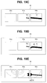
- Fig. 19B is an example in which the endoscope system 1 of the second embodiment is applied to the endoscope system 1 of the fourth embodiment.
- a coordinate position of the side-view field of view image 66b is changed (the side-view field of view image 66b is subjected to parallel translation), and the proximal end of the image 50 of the treatment instrument in the front-view field of view image 66a and the distal end of the image 51 of the treatment instrument in the side-view field of view image 66b are caused to substantially correspond to each other.
Landscapes
- Health & Medical Sciences (AREA)
- Life Sciences & Earth Sciences (AREA)
- Surgery (AREA)
- Physics & Mathematics (AREA)
- Engineering & Computer Science (AREA)
- Optics & Photonics (AREA)
- Medical Informatics (AREA)
- General Health & Medical Sciences (AREA)
- Pathology (AREA)
- Nuclear Medicine, Radiotherapy & Molecular Imaging (AREA)
- Biomedical Technology (AREA)
- Heart & Thoracic Surgery (AREA)
- Biophysics (AREA)
- Molecular Biology (AREA)
- Animal Behavior & Ethology (AREA)
- Radiology & Medical Imaging (AREA)
- Public Health (AREA)
- Veterinary Medicine (AREA)
- General Physics & Mathematics (AREA)
- Astronomy & Astrophysics (AREA)
- Signal Processing (AREA)
- Multimedia (AREA)
- Theoretical Computer Science (AREA)
- Endoscopes (AREA)
- Instruments For Viewing The Inside Of Hollow Bodies (AREA)
- Studio Devices (AREA)
Abstract
Description
- The present invention relates to an endoscope system, and particularly relates to an endoscope system capable of simultaneously observing a front-view direction and a side-view direction.
- Endoscope systems including endoscopes that pick up images of objects inside a subject, image processing apparatuses that generate observation images of the objects which are picked up by the endoscopes, and the like are widely used in medical fields, industrial fields and the like.
- For example, Japanese Patent No.
4955838 - The endoscope picks up an image of the subject observed by the forward side observation lens in a circular region at a center portion of an image pickup device, and picks up an image of the subject observed by the circumferential observation lens in a circular ring region at an outer circumference of the circular region of the same image pickup device. Thereby, an endoscopic image in which the forward side image is formed at the center portion as a circular front-view field of view image, and the image in a circumferential direction is formed in an outer circumferential portion of the front-view field of view image as a side-view field of view image in a circular ring shape is displayed on a monitor.
- Further, Japanese Patent No.
3337682 - The endoscope is provided with image pickup devices respectively in image formation positions of the front-view observation lens and the plurality of side-view observation lenses, and picks up a front-view field of view image and a plurality of side-view field of view images by the image pickup devices. Subsequently, the front-view field of view image is disposed in a center, and a plurality of side-view field of view images are disposed on both sides of the front-view field of view image, which are displayed on a monitor.
- When treatment instruments are inserted through the endoscopes disclosed in Japanese Patent No.
4955838 3337682 - However, in these endoscopes, front-view fields of view and side-view fields of view are in different observation regions, and therefore, slide trajectories of the treatment instruments sometimes become discontinuous in the front-view field of view images and the side-view field of view image. When the images of the treatment instruments become discontinuous like this, the problem that visibility of the treatment instruments, and workability of treatment are reduced arises.
- As the causes of discontinuity of the images of treatment instruments, tilt and shift of the front-view field of view lens and the side-view field of view lens, a working error at a time of frame assembly of an objective optical system, and the like are cited. Preventing the errors which are the cause of the above problem at the time of manufacturing endoscopes causes the problem of increasing time and effort in manufacturing and working the endoscopes, because work and assembly have to be performed extremely precisely.
- Consequently, the present invention has an object to provide an endoscope system capable of enhancing workability of treatment by a treatment instrument under an endoscope having a plurality of fields of view by causing images of an object in fields of view which is observed in a front-view field of view and a side-view field of view, to continue, without increasing time and effort in manufacturing and working the endoscope.
- An endoscope system of one aspect of the present invention includes an insertion portion that is inserted to an inside of an object, a first object image acquisition section that is provided in the insertion portion, and acquires a first object image from a first region of the object, a second object image acquisition section that is provided in the insertion portion, and acquires a second object image from a second region of the object, which at least partially differs from the first region, and an image signal generation section that generates an image signal with the first object image and the second object image arranged side by side so that a predetermined object included in the first object image and the predetermined object included in the second object image are disposed in positions adjacent to each other.
-
-
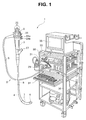
Fig. 1 is a view showing a configuration of an endoscope system according to a first embodiment; -
Fig. 2 is a perspective view showing a configuration of a distal end portion of an insertion portion of an endoscope; -
Fig. 3 is a front view showing the configuration of the distal end portion of the insertion portion of the endoscope; -
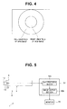
Fig. 4 is a diagram showing an example of an observation image displayed in a monitor; -
Fig. 5 is a diagram showing a configuration of an essential part in the first embodiment; -
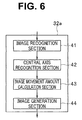
Fig. 6 is a diagram showing a configuration of an image processing section in the first embodiment; -
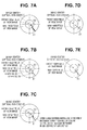
Fig. 7A is a diagram showing an example of an observation image including images of a treatment instrument displayed in the monitor; -
Fig. 7B is a diagram showing an example of the observation image including the images of the treatment instrument displayed in the monitor; -
Fig. 7C is a diagram showing an example of the observation image including the images of the treatment instrument displayed in the monitor; -
Fig. 7D is a diagram showing an example of the observation image including the images of the treatment instrument displayed in the monitor; -
Fig. 7E is a diagram showing an example of the observation image including the images of the treatment instrument displayed in the monitor; -
Fig. 8 is a flowchart for explaining an example of image processing by the image processing section of the first embodiment; -
Fig. 9 is a perspective view showing a configuration of a distal end portion of an insertion portion of an endoscope according to a second embodiment; -
Fig. 10 is a diagram showing a configuration of an essential part in the second embodiment; -
Fig. 11A is a diagram showing an example of an observation image including images of a treatment instrument displayed in a monitor; -
Fig. 11B is a diagram showing an example of the observation image including images of the treatment instrument displayed in the monitors; -
Fig. 12 is a diagram for explaining a configuration of an image processing section according to a third embodiment; -
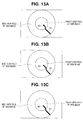
Fig. 13A is a diagram showing an example of an observation image including images of a treatment instrument displayed in a monitor; -
Fig. 13B is a diagram showing an example of the observation image including the images of the treatment instrument displayed in the monitor; -
Fig. 13C is a diagram showing an example of the observation image including the images of the treatment instrument displayed in the monitor; -
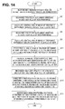
Fig. 14 is a flowchart for explaining an example of image processing by the image processing section of the third embodiment; -
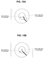
Fig. 15A is a diagram showing an example of the observation image including the images of the treatment instrument displayed in the monitor; -
Fig. 15B is a diagram showing an example of the observation image including the images of the treatment instrument displayed in the monitor; -
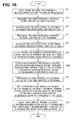
Fig. 16 is a flowchart for explaining an example of image processing by an image processing section of a fourth embodiment; -
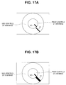
Fig. 17A is a diagram showing an example of an observation image including images of a treatment instrument displayed in a monitor; -
Fig. 17B is a diagram showing an example of the observation image including the images of the treatment instrument displayed in the monitor; -
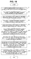
Fig. 18 is a flowchart for explaining an example of image processing by an image processing section of a fifth embodiment; -
Fig. 19A is a diagram showing an example of screen display on an occasion of an endoscope system of the second embodiment being applied to an endoscope system of the third embodiment; -
Fig. 19B is an example in which anendoscope system 1 of the second embodiment is applied to theendoscope system 1 of the fourth embodiment; -
Fig. 19C is an example in which theendoscope system 1 of the second embodiment is applied to theendoscope system 1 of the fifth embodiment; -
Fig. 19D is an example in which theendoscope system 1 of the second embodiment is applied to theendoscope system 1 in which the third, the fourth and the fifth embodiments are combined; -
Fig. 19E is an example in which an image signal is displayed with a redundant portion being deleted from the image signal; -
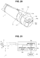
Fig. 20 is a perspective view of adistal end portion 6 of aninsertion portion 4, to which a sideward side observation unit is attached; and -
Fig. 21 is a diagram showing a configuration of an essential part in a sixth embodiment. - Hereinafter, embodiments of the present invention will be described with reference to the drawings.
- At first, a configuration of an endoscope system of a first embodiment will be described with use of
Fig. 1 to Fig. 8 .Fig. 1 is a view showing a configuration of the endoscope system according to the first embodiment.Fig. 2 is a perspective view showing a configuration of a distal end portion of an insertion portion of an endoscope.Fig. 3 is a front view showing the configuration of the distal end portion of the insertion portion of the endoscope.Fig. 4 is a diagram showing an example of an observation image displayed in a monitor.Fig. 5 is a diagram showing a configuration of an essential part in the first embodiment.Fig. 6 is a diagram showing a configuration of an image processing section in the first embodiment.Fig. 7A to Fig. 7E are diagrams each showing an example of the observation image including images of a treatment instrument displayed in the monitor. Further,Fig. 8 is a flowchart for explaining an example of image processing. - As shown in
Fig. 1 , anendoscope system 1 has anendoscope 2 that picks up an image of an observation object and outputs an image pickup signal, alight source apparatus 31 that supplies illuminating light for illuminating an observation object, avideo processor 32 having a function as an image signal generation section that generates and outputs a video signal (an image signal) corresponding to an image pickup signal, and amonitor 35 that displays an observation image corresponding to a video signal (an image signal). - The
endoscope 2 is configured by having anoperation portion 3 for a surgeon to grasp to perform an operation, anelongated insertion portion 4 that is formed at a distal end side of theoperation portion 3 and is inserted into a body cavity or the like, and auniversal cord 5 that has one end portion provided to extend from a side portion of theoperation portion 3. - The
endoscope 2 of the present embodiment is a wide-angle endoscope capable of observing a field of view of 180 degrees or more by displaying a plurality of field of view images, and realizes prevention of omission of a lesion of a location that is difficult to see only by observation in a front-view direction, such as a back of a fold, a boundary of organs, or the like in a body cavity, in particular, in a large intestine. When theinsertion portion 4 of theendoscope 2 is inserted into a large intestine, actions occur, such as twisting, a reciprocating motion, and temporary fixation by performing hooking on an intestinal wall, as in an ordinary colonoscope. - The
insertion portion 4 is configured by having a rigiddistal end portion 6 provided at a most distal end side, abendable bending portion 7 provided at a rear end of thedistal end portion 6, and aflexible tube portion 8 that is provided at a rear end of the bendingportion 7, and has a long length and flexibility. Further, the bendingportion 7 performs a bending action corresponding to an operation of a bendingoperation lever 9 provided at theoperation portion 3. - As shown in
Fig. 2 , on thedistal end portion 6 of theinsertion portion 4, acylinder portion 10 in a circular column shape that is provided to protrude from a position eccentric to an upper side from a center of a distal end face of thedistal end portion 6 is formed. - An objective optical system not illustrated that is used for both a front view and a side view is provided at a distal end portion of the
cylinder portion 10. Further, the distal end portion of thecylinder portion 10 is configured by having a front-view observation window 12 that is disposed in a spot corresponding to a front-view direction of the aforementioned objective optical system not illustrated, and a side-view observation window 13 that is disposed in a spot corresponding to a side-view direction of the aforementioned objective optical system not illustrated. Furthermore, a side-view illumination section 14 that emits light for illuminating the side-view direction is formed in a vicinity of a proximal end of thecylinder portion 10. - The side-
view observation window 13 includes a side-view mirror lens 15 for enabling acquisition of a side-view field of view image by capturing return light (reflection light) from an observation object that is incident from a circumferential direction in thecylinder portion 10 in the circular column shape, in a side-view field of view. - Note that (an image pickup face of) an
image pickup device 30 shown inFig. 5 is disposed in an image formation position of the aforementioned objective optical system not illustrated, so that an image of an observation object in a field of view of the front-view observation window 12 is formed in a center portion as a circular front-view field of view image, and an image of the observation object in a field of view of the side-view observation window 13 is formed in an outer circumferential portion of the front-view field of view image as a side-view field of view image in a circular ring shape. - Such an image is realized by using a double reflection optical system that reflects returning light twice by the side-
view mirror lens 15, but an image may be formed by returning light being reflected once by a single reflection optical system, and is subjected to image processing by thevideo processor 32, and orientations of the side-view field of view image and the front-view field of view image may be matched with each other. - A front-
view illuminating window 16 that is disposed in a position adjacent to thecylinder portion 10 and emits illuminating light to a range of a front-view field of view of the front-view observation window 12, and a distalend opening portion 17 that communicates with a treatment instrument channel not illustrated that is formed by a tube or the like placed in theinsertion portion 4, and enables (a distal end portion of) a treatment instrument inserted through the treatment instrument channel to protrude are provided on the distal end face of thedistal end portion 6. - Further, the
distal end portion 6 of theinsertion portion 4 has asupport portion 18 that is provided to protrude from the distal end face of thedistal end portion 6, and thesupport portion 18 is located adjacently to a lower portion side of thecylinder portion 10. - The
support portion 18 is configured to be able to support (or hold) respective protruding members that are disposed to be protruded from the distal end face of thedistal end portion 6. More specifically, thesupport portion 18 is configured to be able to support (or hold) a front-view observationwindow nozzle portion 19 that injects gas or a liquid for cleaning the front-view observation window 12, a front-view illuminating window 21 that emits light for illuminating a front-view direction, and a side-view observationwindow nozzle portion 22 that injects gas or a liquid for cleaning the side-view observation window 13 as the aforementioned respective protruding members, respectively. - The
support portion 18 is formed by having a shieldingportion 18a that is an optical shielding member for preventing a side-view field of view image that includes any of the respective protruding members from being acquired by the aforementioned respective protruding members which are different matters from an original observation object appearing in the side-view field of view. That is, the shieldingportion 18a is provided at thesupport portion 18, whereby a side-view field of view image in which none of the front-view observationwindow nozzle portion 19, the front-view illuminating window 21 and the side-view observationwindow nozzle portion 22 is included, can be obtained. - As shown in
Fig. 2 and Fig. 3 , the side-view observationwindow nozzle portions 22 are provided at two spots at thesupport portion 18, and are disposed on side faces of thesupport portion 18 so that distal ends protrude. - As shown in
Fig. 1 , a gas/liquidfeeding operation button 24a capable of instructing an operation of causing gas or a liquid for cleaning the front-view observation window 12 to be injected from the front-view observationwindow nozzle portion 19, and a gas/liquidfeeding operation button 24b capable of instructing an operation of causing gas or a liquid for cleaning the side-view observation window 13 to be injected from the side-view observationwindow nozzle portion 22 are provided at theoperation portion 3, and gas feeding and liquid feeding are switchable by depression of the gas/liquidfeeding operation buttons window nozzle portion 19 and the side-view observationwindow nozzle portion 22 by an operation of one gas/liquid feeding operation button, for example. - A plurality of scope switches 25 are provided at a top portion of the
operation portion 3, and have configurations that can be assigned with functions according to the respective switches so as to be caused to output signals corresponding to on, off or the like of various statements usable in theendoscope 2. Specifically, the scope switches 25 can be assigned with functions of being caused to output signals corresponding to start and stop of forward side water feeding, execution and cancel of a freeze, notification of a use state of a treatment instrument and the like, as the functions according to the respective switches. - Note that in the present embodiment, at least one of the functions of the gas/liquid
feeding operation buttons - Further, at the
operation portion 3, asuction operation button 26 is placed, which is capable of performing an instruction for sucking and recovering mucus or the like in a body cavity from the distalend opening portion 17 to a suction unit or the like not illustrated. - The mucus or the like in the body cavity which is sucked in accordance with an action of the suction unit or the like not illustrated passes through the distal
end opening portion 17, the treatment instrument channel not illustrated in theinsertion portion 4, and a treatmentinstrument insertion port 27 provided in a vicinity of a front end of theoperation portion 3, and thereafter is recovered into a suction bottle or the like of the suction unit not illustrated. - The treatment
instrument insertion port 27 is formed as an opening which communicates with the treatment instrument channel not illustrated in theinsertion portion 4, and into which a treatment instrument not illustrated can be inserted. That is, a surgeon can perform treatment using a treatment instrument by inserting the treatment instrument from the treatmentinstrument insertion port 27, and causing a distal end side of the treatment instrument to protrude from the distalend opening portion 17. - As shown in
Fig. 1 , aconnector 29 connectable to thelight source apparatus 31 is provided at the other end portion of theuniversal cord 5. - A pipe sleeve (not illustrated) to be a connection end portion of a fluid conduit, and a light guide pipe sleeve (not illustrated) to be a supply end portion of illuminating light are provided at a distal end portion of the
connector 29. Further, an electric contact point portion (not illustrated) to which one end portion of aconnection cable 33 can be connected is provided at a side face of theconnector 29. Furthermore, a connector for electrically connecting theendoscope 2 and thevideo processor 32 is provided at the other end portion of theconnection cable 33. - In the
universal cord 5, a plurality of signal lines for transmitting various electric signals, and a light guide for transmitting the illuminating light supplied from thelight source apparatus 31 are incorporated in a bundled state. - The aforementioned light guide which is incorporated in the
insertion portion 4 through theuniversal cord 5 has an end portion at a light exit side branched into at least two directions in a vicinity of theinsertion portion 4, and has such a configuration that a light exit end face at one side is disposed in the front-view illuminating windows view illumination section 14. Further, the aforementioned light guide has such a configuration as an end portion at a light incident side is disposed in the light guide pipe sleeve of theconnector 29. - Note that the light exit portions disposed in the front-
view illuminating windows view illumination section 14 may be light emitting devices such as a light emitting diode (LED) in place of the light guide. - The
video processor 32 outputs a drive signal for driving an image pickup device provided at thedistal end portion 6 of theendoscope 2. Thevideo processor 32 functions as an image signal generation section that generates a video signal (an image signal) by applying signal processing to an image pickup signal outputted from the aforementioned image pickup device and outputs the video signal to themonitor 35. - Thereby, an observation image including a front-view field of view image forming a circular shape, and a side-view field of view image forming a circular ring shape in an outer circumference of the image in a front-view direction, that is, an image in which the side-view field of view image is arranged in such a manner as to enclose the front-view field of view image in a state where the side-view field of view image is adjacent to the front-view field of view image is displayed in the
monitor 35 in an aspect as shown inFig. 4 , for example. Note that in each of the observation images shown in the present embodiment and following embodiments, a part that is optically shielded by the shieldingportion 18a of thesupport portion 18 is not taken into consideration. Further, the front-view field of view image and the side-view field of view image which are displayed in themonitor 35 may be respectively in other display aspects without being limited to the circular shape and the circular ring shape shown inFig. 4 . - Peripheral apparatuses such as the
light source apparatus 31, thevideo processor 32 and themonitor 35 are disposed on arack 36 together with akeyboard 34 that performs input of patient information, and the like. - As shown in
Fig. 5 , thevideo processor 32 is configured by having at least animage processing section 32a, and animage output section 32b. - The front-
view observation window 12 configuring a first object image acquisition section acquires a first object image from a front-view direction (a first direction) that is substantially parallel with a longitudinal direction of theinsertion portion 4 and includes a frontward side, that is, a first region of an object, and the side-view observation window 13 configuring a second object image acquiring section acquires a second object image from a side-view direction (a second direction) that at least partially differs from the front-view direction (the first direction) and intersects the longitudinal direction of theinsertion portion 4, that is, a second region of the object. - Note that a boundary region between the first object image and the second object image may be duplicate, or does not have to be duplicate, and in a case of a state where the above described boundary region is duplicate, duplicate object images may be acquired in the first object image acquiring section and the second object image acquiring section.
- The
image pickup device 30 photoelectrically converts the object image in the front-view direction and the object image in the side-view direction on a same plane. Theimage pickup device 30 is electrically connected to theimage processing section 32a, and outputs the object images acquired in the front-view observation window 12 and the side-view observation window 13 to theimage processing section 32a. - The
image processing section 32a recognizes an image of a treatment instrument included in the front-view field of view image, and an image of the treatment instrument included in the side-view field of view image. Subsequently, theimage processing section 32a generates an image signal with disposition changed with respect to at least either the front-view field of view image and the side-view field of view image so that a central axis of the image of the treatment instrument included in the front-view field of view image, and a central axis of the image of the treatment instrument included in the side-view field of view image substantially correspond to each other. - The
image output section 32b generates a signal to be displayed in themonitor 35 from the image signal generated by theimage processing section 32a, and outputs the signal to themonitor 35. - As shown in
Fig. 6 , theimage processing section 32a is configured by having animage recognition section 41, a centralaxis recognition section 42, an image movementamount calculation section 43 and animage generation section 44. - The
image recognition section 41 recognizes an image of a predetermined object, for example, an image of a treatment instrument observed in a side-view field of view, and an image of the treatment instrument observed in a front-view field of view. For example, since a position where the treatment instrument protrudes from the distalend opening portion 17 is fixed, theimage recognition section 41 recognizes a matter which protrudes from a direction of the position and advances as the treatment instrument. Alternatively, theimage recognition section 41 may recognize the treatment instrument by calculating a direction in which the treatment instrument slides from movement, or may recognize the treatment instrument by recognizing a thickness and a contour of the treatment instrument from an image contrast. - The central
axis recognition section 42 calculates central axes of respective images from the image of the treatment instrument observed in the side-view field of view and the image of the treatment instrument observed in the front-view field of view which are recognized by theimage recognition section 41, and recognizes the central axis. For example, as for the central axis, the central axis of the treatment instrument is recognized from the image contrast of the thickness of the treatment instrument, and a moving direction in which the treatment instrument is protruded. - By performing the above processing, the object such as the treatment instrument included in the front-view field of view image, and the object such as the treatment instrument included in the side-view field of view image are disposed in positions which are adjacent to each other without unnaturalness.
- The image movement
amount calculation section 43 calculates an opening angle between the respective central axes from image centers (optical axis centers) of coordinate positions of the respective central axes, with respect to the images of the treatment instrument observed in the front-view field of view and the side-view field of view. - The
image generation section 44 recognizes a boundary between the front-view field of view image and the side-view field of view image, cuts out only the side-view field of view image, rotationally moves the side-view field of view image with an image center as a starting point on the basis of the opening angle calculated by the image movementamount calculation section 43 so that the coordinates of inclinations of the images of the treatment instrument correspond to each other, and generates an image signal with the central axis of the image of the treatment instrument observed in the side-view field of view, and the central axis of the image of the treatment instrument observed in the front-view field of view substantially corresponding to each other. - Note that the
image generation section 44 may rotationally move the front-view field of view image, or may rotationally move both of the front-view field of view image and the side-view field of view image, so that the image of the treatment instrument in the front-view field of view image and the image of the treatment instrument in the side-view field of view image substantially correspond to each other. - For example, when an
image 50 of the treatment instrument in the front-view field of view image, and animage 51 of the treatment instrument in the side-view field of view image deviate from each other as shown inFig. 7A , theimage generation section 44 causes central axes of theimage 50 of the treatment instrument in the front-view field of view image, and theimage 51 of the treatment instrument in the side-view field of view image to substantially correspond to each other by rotationally moving the side-view field of view image with the image center as the starting point, as shown inFig. 7D . - Note that the
image generation section 44 may rotationally move the front-view field of view image with an image center as the starting point as shown inFig. 7E . Further, theimage generation section 44 may cause the central axis of the image of the treatment instrument in the front-view field of view image and the central axis of the image of the treatment instrument in the side-view field of view image to substantially correspond to each other by rotationally moving both of the side-view field of view image and the front-view field of view image. - Next, an operation of the
endoscope system 1 configured in this way will be described. -
Fig. 8 is a flowchart for explaining an example of image processing by the image processing section of the present embodiment. Note that in the flowchart inFig. 8 , processing of rotationally moving the side-view field of view image with the image center as the starting point so as to cause the central axes of the treatment instrument to substantially correspond to each other will be described, but the processing is not limited to this. For example, processing of rotationally moving the front-view field of view image with the image center as the starting point may be performed, or processing of rotationally moving both of the front-view field of view image and the side-view field of view image with the image centers as the starting points may be performed. - When the treatment instrument is inserted through the treatment instrument channel first, and the treatment instrument protrudes from the distal end opening portion 17 (step S1), the
image recognition section 41 recognizes the treatment instrument observed in the side-view field of view from the image (step S2). Next, as inFig. 7B , the centralaxis recognition section 42 calculates the central axis of the image of the treatment instrument observed in the side-view field of view (step S3). - When the treatment instrument further protrudes, the image of the treatment instrument is observed in the front-view field of view. Thereupon, the
image recognition section 41 recognizes the treatment instrument observed in the front-view field of view from the image (step S4), and as inFig. 7B , the centralaxis recognition section 42 calculates the central axis of the image of the treatment instrument observed in the front-view field of view (step S5). - Next, as shown in
Fig. 7C , the image movementamount calculation section 43 calculates the opening angle between the respective central axes from the coordinate positions of the respective central axes (step S6). The opening angle is a correction angle of the central axis of the image of the treatment instrument observed in the side-view field of view which is parallel to the central axis of the image of the treatment instrument observed in the front-view field of view, which is calculated by the image movementamount calculation section 43. - The
image generation section 44 recognizes only the side-view field of view image and cuts out only the side-view field of view image (step S7). Theimage generation section 44 rotationally moves the side-view field of view image which is cut out with the image center as the starting point so that inclinations of the respective central axes of the treatment instrument correspond to each other (step S8). Finally, theimage generation section 44 generates the image signal with the central axis of the image of the treatment instrument in the front-view field of view image and the central axis of the image of the treatment instrument in the side-view field of view image substantially corresponding to each other (step S9), and ends processing. The image signal which is generated in this way is displayed in themonitor 35 via theimage output section 32b. - As above, the
endoscope system 1 detects a deviation between the image of the treatment instrument of the front-view field of view image and the image of the treatment instrument of the side-view field of view image, rotates the front-view field of view image or the side-view field of view image in accordance with an amount of the deviation, and causes the central axes of the image of the treatment instrument in the front-view field of view image and the image of the treatment instrument in the side-view field of view image to substantially correspond to each other. Thereby, the central axes of the images of the treatment instrument in the front-view field of view image and the side-view field of view image substantially correspond to each other, and therefore, visibility and operability of the treatment instrument can be enhanced. Further, since the front-view field of view image or the side-view field of view image is rotated with the image center as the starting point, the axes of the treatment instrument can be caused to correspond to each other without sizes of the respective images and centers of the respective images being changed. - Consequently, according to the endoscope system of the present embodiment, the objects (the images of the treatment instrument or the like) within the field of view which is observed in the front-view field of view and the side-view field of view are caused to continue to each other without time and effort in manufacturing and working an endoscope being increased, whereby workability of treatment by the treatment instrument under the endoscope having a plurality of fields of view can be enhanced.
- Note that as the images of the object the positions of which are caused to correspond to each other, the image of the object is not limited to the treatment instrument, but may be another element such as a fold in a body cavity, or a stent or a clip dwelling in a body cavity, and positioning may be performed by performing recognition of the objects in the front-view field of view and the side-view field of view according to the procedure similar to the procedure described above, and performing rotational movement of the front-view field of view or the side-view field of view.
- Next, a second embodiment will be described.
-
Fig. 9 is a perspective view showing a configuration of a distal end portion of an insertion portion of an endoscope according to the second embodiment. - As shown in
Fig. 9 , on a distal end face of adistal end portion 6a of anendoscope 2a, a front-view observation window 60a for observing a front-view direction (a first direction) that is substantially parallel with the longitudinal direction of theinsertion portion 4 and includes a forward side, that is, a first region of an object is disposed, and on a side face of thedistal end portion 6a of theendoscope 2a, side-view observation windows insertion portion 4, that is, a second region of the object are disposed. The side-view observation windows distal end portion 6a, for example, an interval of 180 degrees. The front-view observation window 60a configures the first object image acquisition section, and at least one of the side-view observation windows - Note that the number of the side-
view observation windows distal end portion 6a is not limited to two, but a configuration in which one side-view observation window is disposed may be adopted, for example. Further, as for the side-view observation windows distal end portion 6a, for example, a configuration in which the side-view observation windows are disposed every 120 degrees in the circumferential direction (that is, three side-view field of view images are acquired), may be adopted, or a configuration in which the side-view observation windows are disposed every 90 degrees in the circumferential direction (that is, four side-view field of view images are acquired) may be adopted. - On the distal end face of the
distal end portion 6a of theendoscope 2a, front-view illuminating windows view observation window 60a are disposed in positions adjacent to the front-view observation window 60a. Further, on side face of thedistal end portion 6a of theendoscope 2a, side-view illuminating windows view observation window 60b are disposed in positions adjacent to the side-view observation window 60b, and side-view illuminating windows view observation window 60c are disposed in positions adjacent to the side-view observation window 60c. A distalend opening portion 63 from which atreatment instrument 64 protrudes is provided at a rear side of the side-view observation window 60b on the side face of thedistal end portion 6a. - Note that as light exit sections that emit illuminating light from the front-
view illuminating windows view illuminating windows view illuminating windows -
Fig. 10 is a diagram showing a configuration of an essential part in the second embodiment, andFig. 11A and Fig. 11B are diagrams showing examples of the observation image including images of the treatment instrument which are displayed in the monitors. - As shown in
Fig. 10 , animage pickup device 65a is disposed in an image formation position of the front-view observation window 60a and an objective optical system not illustrated. Further, animage pickup device 65b is disposed in an image formation position of the side-view observation window 60b and the objective optical system not illustrated, and animage pickup device 65c is disposed in an image formation position of the side-view observation window 60c and the objective optical system not illustrated. - The
image pickup devices 65a to 65c are electrically connected to theimage processing section 32a of thevideo processor 32 which has the function as the image signal generation section respectively, and output a front-view field of view image which is picked up by theimage pickup device 65a and side-view field of view images which are picked up by the respectiveimage pickup devices image processing section 32a. - As shown in
Fig. 11A , theimage processing section 32a generates an image signal so as to dispose a front-view field ofview image 66a that is picked up by theimage pickup device 65a in a center of themonitor 35, and dispose a side-view field ofview image 66b that is picked up by theimage pickup device 65b and a side-view field ofview image 66c that is picked up by theimage pickup device 65c side by side in a state where the side-view field ofview image 66b and the side-view field ofview image 66c are adjacent to be on both sides of the front-view field ofview image 66a respectively. - Further, the
image processing section 32a rotationally moves the side-view field ofview image 66b so that the central axis of theimage 50 of the treatment instrument in the front-view field ofview image 66a, and the central axis of theimage 51 of the treatment instrument in the side-view field ofview image 66b substantially correspond to each other. At this time, theimage processing section 32a also rotationally moves the side-view field ofview image 66c by a same moving amount as a rotational moving amount of the side-view field ofview image 66b, in an opposite direction to the side-view field ofview image 66b. - Note that the rotationally moving processing by the
image processing section 32a is similar to the rotationally moving processing in the first embodiment. Further, when a plurality of images are displayed in themonitor 35, the front-view field of view image and the side-view field of view image can be adjacent to each other, and the configuration is not limited to only the configuration in which the side-view field ofview images view image 66a, but may be a configuration in which the side-view field of view image, for example, only the side-view field ofview image 66b in which theimage 51 of the treatment instrument is displayed, is disposed at either one of left or right side of the front-view field ofview image 66a. - Further, in the present embodiment, a plurality of images are displayed in the
monitor 35, but the present invention is not limited to this. For example, as shown inFig. 11B , like a configuration in which a plurality, for example, three of themonitors 35 are disposed adjacently to one another, the front-view field ofview image 66a is displayed in thecentral monitor 35, and the side-view field ofview images monitors 35 at both sides, a configuration in which themonitor 35 displaying the front-view field of view image and themonitors 35 displaying the side-view field of view images are adjacent to one another may be adopted. - As above, even in the configuration in which the front-
view observation window 60a which acquires the front-view field of view image is provided on the distal end face of thedistal end portion 6a, the plurality of side-view observation windows distal end portion 6a, and the plurality of images (the front-view field ofview image 66a, and the side-view field ofview images monitor 35, the central axes of theimage 50 of the treatment instrument in the front-view field ofview image 66a and theimage 51 of the treatment instrument in the side-view field ofview image 66b also can be caused to substantially correspond to each other. - As a matter of course, as in the first embodiment, the image of the object is not limited to the image of the treatment instrument, and may be an image of another element observed in the field of view.
- Consequently, according to the
endoscope system 1 of the present embodiment, the objects (the images of the treatment instrument or the like) within the field of view observed in the front-view field of view and the side-view field of view are caused to be adjacent to each other without unnaturalness in such a manner as to be caused to continue to each other, without time and effort in manufacturing and working an endoscope being increased, whereby workability of treatment by the treatment instrument under the wide-angle endoscope can be enhanced. - Next, a third embodiment will be described.
- An endoscope system of the present embodiment has a similar configuration to the configuration of the first embodiment, and differs from the first embodiment in the configuration of the
image processing section 32a. -
Fig. 12 is a diagram for explaining a configuration of an image processing section according to the third embodiment,Fig. 13A to Fig. 13C are diagrams showing examples of an observation image including images of the treatment instrument displayed in the monitor. Note that inFig. 12 , the same components as the components inFig. 6 are assigned with the same reference signs and explanation will be omitted. - As shown in
Fig. 12 , theimage processing section 32a of the present embodiment is configured by including an image enlargement/reductionratio calculation section 70 in place of the image movementamount calculation section 43 inFig. 6 . - The image enlargement/reduction
ratio calculation section 70 detects a proximal end of theimage 50 of the treatment instrument in the front-view field of view image, and a distal end of theimage 51 of the treatment instrument in the side-view field of view image respectively from predetermined objects, for example, the central axis of theimage 50 of the treatment instrument in the front-view field of view image, and the central axis of theimage 51 of the treatment instrument in the side-view field of view image which are recognized by the centralaxis recognition section 42. Subsequently, the image enlargement/reductionratio calculation section 70 calculates an enlargement/reduction ratio of the front-view field of view image or the side-view field of view image, with which the proximal end of theimage 50 of the treatment instrument in the front-view field of view image and the distal end of theimage 51 of the treatment instrument of the side-view field of view image which are detected substantially correspond to each other. - The
image generation section 44 changes a display magnification of the front-view field of view image or the side-view field of view image longitudinally and laterally (distorts the front-view field of view image or the side-view field of view image) so that the proximal end of theimage 50 of the treatment instrument in the front-view field of view image and the distal end of theimage 51 of the treatment instrument in the side-view field of view image which are detected substantially correspond to each other, on the basis of the enlargement/reduction ratio which is calculated by the image enlargement/reductionratio calculation section 70. - Note that when the
image generation section 44 changes the display magnification of the side-view field of view image longitudinally and laterally, for example, theimage generation section 44 changes the magnification of only a vicinity of theimage 51 of the treatment instrument, instead of changing the magnification of the entire side-view field of view image. Thereby, an image of the vicinity of theimage 51 of the treatment instrument is changed, and thereby an influence is not given to a deviation of the entire image. - Further, the
image generation section 44 may change the display magnifications of the front-view field of view image and the side-view field of view image longitudinally and laterally. The magnifications of both of the field of view images are changed in this way, whereby distortion amounts of the respective field of view images decrease, and unnaturalness due to distortion can be reduced. - In
Fig. 13A , for example, the display magnification of the front-view field of view image is changed longitudinally and laterally, and the proximal end of theimage 50 of the treatment instrument in the front-view field of view image and the distal end of theimage 51 of the treatment instrument in the side-view field of view image are caused to substantially correspond to each other. Further, inFig. 13B , the display magnification of the side-view field of view image is changed longitudinally and laterally, and the proximal end of theimage 50 of the treatment instrument in the front-view field of view image and the distal end of theimage 51 of the treatment instrument in the side-view field of view image are caused to substantially correspond to each other. Further, inFig. 13C , the display magnifications of the front-view field of view image and the side-view field of view image are changed longitudinally and laterally, and the proximal end of theimage 50 of the treatment instrument of the front-view field of view image and the distal end of theimage 51 of the treatment instrument of the side-view field of view image are caused to substantially correspond to each other. - Next, an operation of the
endoscope system 1 that is configured as above will be described. -
Fig. 14 is a flowchart for explaining an example of image processing by the image processing section of the third embodiment. Note that inFig. 14 , the same processings as inFig. 8 are assigned with the same reference signs, and explanation will be omitted. Further, in the flowchart inFig. 14 , an example in which the display magnification of the side-view field of view image is changed longitudinally and laterally is explained, but the display magnification of the front-view field of view image may be changed longitudinally and laterally, or the display magnifications of the front-view field of view image and the side-view field of view image may be changed longitudinally and laterally, as described above. - When the central axis of the image of the treatment instrument observed in the front-view field of view is calculated in step S5, the image enlargement/reduction
ratio calculation section 70 detects the proximal end of the image of the treatment instrument of the front-view field of view image, and the distal end of the image of the treatment instrument of the side-view field of view image (step S11). Next, the image enlargement/reductionratio calculation section 70 calculates the enlargement/reduction ratio of the image of the treatment instrument observed in the side-view field of view, that substantially corresponds to the proximal end of the image of the treatment instrument observed in the front-view field of view (step S12). - Next, when only the side-view field of view image is recognized and only the side-view field of view image is cut out in step S7, the
image generation section 44 changes the display magnification of the side-view field of view image longitudinally and laterally so that the proximal end of the image of the treatment instrument in the front-view field of view image and the distal end of the image of the treatment instrument in the side-view field of view image substantially correspond to each other (step S13). Finally, theimage generation section 44 generates an image signal with the proximal end of the image of the treatment instrument in the front-view field of view image and the distal end of the image of the treatment instrument in the side-view field of view image substantially corresponding to each other (step S 14), and ends the processing. The image signal which is generated in this way is displayed in themonitor 35 via theimage output section 32b. - As above, the
endoscope system 1 detects a deviation between the image of the treatment instrument in the front-view field of view image and the image of the treatment instrument in the side-view field of view image, causes the magnification of only the vicinity of the image of the treatment instrument in the front-view field of view image or the side-view field of view image to be changed in accordance with an amount of the deviation, and causes the proximal end of the image of the treatment instrument in the front-view field of view image and the distal end of the image of the treatment instrument in the side-view field of view image to substantially correspond to each other. Thereby, the images of the treatment instrument in the front-view field of view image and the side-view field of view image are connected continuously, and therefore visibility and operability of the treatment instrument can be enhanced. - Consequently, according to the endoscope system of the present embodiment, similar effects to the effects of the first embodiment are provided, and since only the magnification of the vicinity of the image of the treatment instrument in the front-view field of view image or the side-view field of view image is changed, an influence is not given to a deviation of the entire image.
- Next, a fourth embodiment will be described.
- A configuration of the
image processing section 32a of the present embodiment is similar to the configuration of theimage processing section 32a of the first embodiment inFig. 6 , and only processing different from the processing of theimage processing section 32a of the first embodiment will be described. - The image movement
amount calculation section 43 detects the proximal end of theimage 50 of the treatment instrument in the front-view field of view image, and the distal end of theimage 51 of the treatment instrument in the side-view field of view image, and calculates such an image movement amount that allows the proximal end and the distal end to substantially correspond to each other. - The
image generation section 44 moves a coordinate position of the front-view field of view image or the side-view field of view image based on the image movement amount calculated in the image movementamount calculation section 43. -
Fig. 15A and Fig. 15B are diagrams showing an example of an observation image including images of the treatment instrument displayed in the monitor. - In the example in
Fig. 15A and Fig. 15B , coordinates of the front-view field of view image are moved diagonally downward to a left when viewed from the front of the drawings, whereby the central axes of theimage 50 of the treatment instrument in the front-view field of view image and theimage 51 of the treatment instrument in the side-view field of view image substantially correspond to each other. Note that the image the coordinates of which are moved is not limited to the front-view field of view image, but the coordinates of the side-view field of view image may be moved, or the coordinates of both of the front-view field of view image and the side-view field of view image may be moved. - Next, an operation of the endoscope system configured as above will be described.
-
Fig. 16 is a flowchart for explaining an example of image processing by the image processing section of the fourth embodiment. Note that inFig. 16 , the processings similar to the processings inFig. 8 are assigned with the same reference signs, and explanation will be omitted. Further, in the flowchart inFig. 16 , an example in which the coordinates of the side-view field of view image are moved is described, but the coordinates of the front-view field of view image may be moved, or the coordinates of the front-view field of view image and the side-view field of view image may be moved, as described above. - When the central axis of the image of the treatment instrument observed in the front-view field of view is calculated in step S5, the image movement
amount calculation section 43 detects the proximal end of the image of the treatment instrument in the front-view field of view image, and the distal end of the image of the treatment instrument in the side-view field of view image (step S21). Next, the image movementamount calculation section 43 calculates such a movement amount of the side-view field of view image that allows the proximal end of the image of the treatment instrument observed in the front-view field of view and the distal end of the image of the treatment instrument observed in the side-view field of view to substantially correspond to each other (step S22). - Next, when only the side-view field of view image is recognized and only the side-view field of view image is cut out in step S7, the
image generation section 44 moves the coordinates of the side-view field of view image so that the proximal end of the image of the treatment instrument in the front-view field of view image and the distal end of the image of the treatment instrument in the side-view field of view image substantially correspond to each other (step S23). Finally, theimage generation section 44 generates an image signal with the proximal end of the image of the treatment instrument in the front-view field of view image and the distal end of the image of the treatment instrument in the side-view field of view image substantially corresponding to each other (step S24), and ends the processing. The image signal which is generated in this way is displayed in themonitor 35 via theimage output section 32b. - As above, the
endoscope system 1 detects a deviation between the image of the treatment instrument in the front-view field of view image and the image of the treatment instrument in the side-view field of view image, moves the coordinates of the front-view field of view image or the side-view field of view image in accordance with an amount of the deviation, and causes the proximal end of the image of the treatment instrument in the front-view field of view image and the distal end of the image of the treatment instrument in the side-view field of view image to substantially correspond to each other. Thereby, the central axes of the images of the treatment instrument in the front-view field of view image and the side-view field of view image substantially correspond to each other, and therefore visibility and operability of the treatment instrument can be enhanced. - Consequently, according to the endoscope system of the present embodiment, similar effects to the effects of the first embodiment are provided. Since the coordinates displaying the front-view field of view image or the side-view field of view image are only changed, distortion and the image which is seen do not have to be changed, and visibility and operability of the treatment instrument can be further enhanced.
- Next, a fifth embodiment will be described.
- A configuration of the
image processing section 32a of the present embodiment is similar to the configuration of theimage processing section 32a of the third embodiment inFig. 12 , and only processing different from the processing of theimage processing section 32a of the third embodiment will be described. - The image enlargement/reduction
ratio calculation section 70 calculates an enlargement ratio of theimage 51 of the treatment instrument in the side-view field of view image, which overlaps the central axis of theimage 50 of the treatment instrument in the front-view field of view image, from the central axis of theimage 50 of the treatment instrument in the front-view field of view image, and the central axis of theimage 51 of the treatment instrument in the side-view field of view image, which are recognized by the centralaxis recognition section 42 for the image of the treatment instrument. - The
image generation section 44 cuts out only theimage 51 of the treatment instrument in the side-view field of view image from the side-view field of view image, and enlarges theimage 51 of the treatment instrument in the side-view field of view image on the basis of the enlargement ratio calculated in the image enlargement/reductionratio calculation section 70. -
Fig. 17A and Fig. 17B are diagrams showing an example of an observation image including images of the treatment instrument displayed in the monitor. - In the example in
Fig. 17A and Fig. 17B , only theimage 51 of the treatment instrument in the side-view field of view image is enlarged, so that theimage 51 of the treatment instrument in the side-view field of view image overlaps the central axis of theimage 50 of the treatment instrument in the front-view field of view image. Note that the image of the treatment instrument which is enlarged is not limited to theimage 51 of the treatment instrument in the side-view field of view image, but theimage 50 of the treatment instrument in the front-view field of view image may be enlarged, or both of theimage 50 of the treatment instrument in the front-view field of view image and theimage 51 of the treatment instrument in the side-view field of view image may be enlarged. - Next, an operation of the endoscope system that is configured as above will be described.
-
Fig. 18 is a flowchart for explaining an example of image processing by the image processing section of the fifth embodiment. Note that inFig. 18 , the processings similar to the processings inFig. 8 are assigned with the same reference signs, and explanation will be omitted. Further, in the flowchart inFig. 18 , an example of enlarging the image of the treatment instrument in the side-view field of view image is described, but the image of the treatment instrument in the front-view field of view image may be enlarged, or the images of the treatment instrument in the front-view field of view image and the side-view field of view image may be enlarged, as described above. - When the central axis of the image of the treatment instrument observed in the front-view field of view is calculated in step S5, the image enlargement/reduction
ratio calculation section 70 calculates an enlargement ratio of the image of the treatment instrument in the side-view field of view image, with which the central axis of the image of the treatment instrument observed in the front-view field of view, and the image of the treatment instrument observed in the side-view field of view overlap each other (step S31). - Next, the
image generation section 44 recognizes only the side-view field of view image, and cuts out only the image of the treatment instrument in the side-view field of view image (step S32). Subsequently, theimage generation section 44 enlarges the image of the treatment instrument in the side-view field of view image so that the central axis of the image of the treatment instrument in the front-view field of view image and the image of the treatment instrument in the side-view field of view image overlap each other (step S33). Finally, theimage generation section 44 generates an image signal with the central axis of the image of the treatment instrument in the front-view field of view image, and the image of the treatment instrument in the side-view field of view image overlapping each other (step S34), and ends the processing. The image signal which is generated in this way is displayed in themonitor 35 via theimage output section 32b. - As above, the
endoscope system 1 detects a deviation between the image of the treatment instrument in the front-view field of view image and the image of the treatment instrument in the side-view field of view image, and changes the enlargement ratio of the image of the treatment instrument in the front-view field of view image or the side-view field of view image in accordance with an amount of the deviation. Subsequently, theendoscope system 1 causes the image of the treatment instrument in the front-view field of view image and the central axis of the image of the treatment instrument in the side-view field of view image to overlap each other, or causes the central axis of the image of the treatment instrument in the front-view field of view image and the image of the treatment instrument in the side-view field of view image to overlap each other. Thereby, the image of the treatment instrument in the front-view field of view image and the image of the treatment instrument in the side-view field of view image substantially correspond to each other, and therefore visibility and operability of the treatment instrument can be enhanced. - Consequently, according to the endoscope system of the present embodiment, similar effects to the effects of the first embodiment are provided. Since the enlargement ratio of only a portion of the image of the treatment instrument is changed, processing for the entire screen does not have to be performed as compared with the aforementioned respective embodiments, and a load of the image processing can be reduced.
- Note that the
endoscope system 1 of the second embodiment in which a plurality of images are disposed adjacently to each other in themonitor 35 may be applied to theendoscope systems 1 of the third embodiment to the fifth embodiment.Fig. 19A to Fig. 19E are diagrams showing examples of screen display at a time of the endoscope system of the second embodiment being applied to the endoscope systems of the third embodiment to the fifth embodiment. -
Fig. 19A is an example in which theendoscope system 1 of the second embodiment is applied to theendoscope system 1 of the third embodiment. As shown inFig. 19A , theimage 51 of the treatment instrument in the side-view field ofview image 66b is distorted, and the central axis of theimage 50 of the treatment instrument in the front-view field ofview image 66a and the central axis of theimage 51 of the treatment instrument in the side-view field ofview image 66b are caused to substantially correspond to each other. - Further,
Fig. 19B is an example in which theendoscope system 1 of the second embodiment is applied to theendoscope system 1 of the fourth embodiment. As shown inFig. 19B , a coordinate position of the side-view field ofview image 66b is changed (the side-view field ofview image 66b is subjected to parallel translation), and the proximal end of theimage 50 of the treatment instrument in the front-view field ofview image 66a and the distal end of theimage 51 of the treatment instrument in the side-view field ofview image 66b are caused to substantially correspond to each other. - At this time, the side-view field of
view image 66b and an area displaying the side-view field ofview image 66b may be simultaneously subjected to parallel translation, but a setting may be adopted, in which the area displaying the side-view field ofview image 66b is not moved, and only the side-view field ofview image 66b is subjected to parallel translation. - Further,
Fig. 19C is an example in which theendoscope system 1 of the second embodiment is applied to theendoscope system 1 of the fifth embodiment. As shown inFig. 19C , only theimage 51 of the treatment instrument in the side-view field of view image is enlarged, and the central axis of theimage 50 of the treatment instrument in the front-view field ofview image 66a and theimage 51 of the treatment instrument in the side-view field ofview image 66b are caused to substantially correspond to each other. - Further,
Fig. 19D is an example in which theendoscope system 1 of the second embodiment is applied to theendoscope system 1 in which the third, the fourth and the fifth embodiments are combined, andFig. 19E is an example in which duplicated portions are deleted from the image signal, and the image signal is displayed. - As shown in
Fig. 19D , parallel translation shown inFig. 19B is performed, and deformation and enlargement processing shown inFig. 19A andFig. 19C may be combined with the parallel translation. Further, in the case of the embodiment in which a plurality of screens are displayed like this, if duplicated portions are generated in two adjacent image signals, thevideo processor 32 may delete the duplicate portions from the image signals, and allow the image signals be displayed (refer toFig. 19E ). - Further, in each of the second embodiment and the respective modifications described above, the mechanisms which realize the functions of illuminating and observing a sideward side are incorporated in the
distal end portion 6 of theinsertion portion 4 together with the mechanisms that realize the functions of illuminating and observing a forward side, but the mechanisms which realize the functions of illuminating and observing the sideward side may be made separate bodies attachable to and detachable from theinsertion portion 4. -
Fig. 20 is a perspective view of thedistal end portion 6 of theinsertion portion 4 to which a unit for sideward side observation is attached. Thedistal end portion 6 of theinsertion portion 4 has a forwardside view unit 100. A sidewardside view unit 110 has a configuration attachable to and detachable from the forwardside view unit 100 by aclip portion 111. - The sideward
side view unit 110 has twoobservation windows 112 for acquiring images in a lateral direction, and two illuminatingwindows 113 for illuminating the lateral direction. - The
video processor 32 or the like performs lighting and extinguishing of the respective illuminatingwindows 113 of the sidewardside view unit 110 in accordance with a frame rate of a forward side field of view, and can perform acquisition and display of the observation image as shown in the above described embodiments. - Next, a sixth embodiment will be described.
-
Fig. 21 is a diagram showing a configuration of an essential part in the sixth embodiment. Note that inFig. 21 , the similar components to the components inFig. 5 are assigned with the same reference signs, and explanation will be omitted. - As shown in
Fig. 21 , thevideo processor 32 is configured by a settingstorage section 32c being added to the video processor inFig. 5 . - In each of the respective embodiments described above, at the time of treatment by the treatment instrument (that is, when the treatment instrument is observed by the endoscope 2), the deviation amount between the
image 50 of the treatment instrument in the front-view field of view image and theimage 51 of the treatment instrument in the side-view field of view image is calculated, and image correction is performed. - In contrast to the above, in the present embodiment, the treatment instrument is protruded from the distal
end opening portion 17 after assembly of theendoscope 2, instead of at the time of treatment by the treatment instrument, and the deviation amount between the image of the treatment instrument in the front-view field of view image and the image of the treatment instrument of the side-view field of view image is calculated for each of theendoscopes 2 in advance. Subsequently, the settingstorage section 32c stores the deviation amount calculated after assembly of theendoscope 2 as endoscope information. - The
image processing section 32a subjects the front-view field of view image or the side-view field of view image to image correction on the basis of the endoscope information (the deviation amount) which is stored in the settingstorage section 32c in advance at the time of endoscope observation. As the image correction, any of image corrections in the aforementioned respective embodiments can be used. - As above, the
endoscope system 1 stores the deviation amount in each of theendoscopes 2 in the settingstorage section 32c as the endoscope information in advance, and performs image correction by using the endoscope information, whereby theendoscope system 1 can cause theimage 50 of the treatment instrument in the front-view field of view image and theimage 51 of the treatment instrument in the side-view field of view image to substantially correspond to each other, as in the aforementioned respective embodiments. Furthermore, since theendoscope system 1 performs image correction by using the endoscope information which is stored in the settingstorage section 32c in advance, theendoscope system 1 can display the front-view field of view image and the side-view field of view image with the deviation amount corrected, in themonitor 35, even in a state where theendoscope system 1 does not recognize the image of the treatment instrument, that is, in a state where treatment is not performed by using the treatment instrument. - Consequently, according to the endoscope system of the present embodiment, effects similar to the effects of the first embodiment are provided, and even in the state where the image of the treatment instrument is not recognized, the front-view field of view image and the side-view field of view image with the deviation amount corrected can be displayed in the
monitor 35. - Note that image correction may be automatically turned on or off in response to presence and absence of insertion of the treatment instrument, or a changeover switch or the like is provided, and image correction may be enabled to be turned on or off manually. The switching of image correction also can be similarly applied to the first embodiment to the fifth embodiment described above.
- Note that as for the respective steps in the flowcharts in the present description, execution sequences may be changed, a plurality of steps may be simultaneously executed, or the respective steps may be executed in a different sequence at each execution, as long as it is not against the characteristics of the respective steps.
- The present invention is not limited to the aforementioned embodiments, and various modifications, alterations and the like can be made within the range without departing from the gist of the present invention.
- The present application claims benefit of Japanese Patent Application No.
2014-26833 filed in Japan on February 14, 2014
Claims (15)
- An endoscope system, comprising:an insertion portion that is inserted to an inside of an object;a first object image acquisition section that is provided in the insertion portion, and acquires a first object image from a first region of the object;a second object image acquisition section that is provided in the insertion portion, and acquires a second object image from a second region of the object, which at least partially differs from the first region; andan image signal generation section that generates an image signal with the first object image and the second object image arranged side by side so that a predetermined object included in the first object image and the predetermined object included in the second object image are disposed in positions adjacent to each other.
- The endoscope system according to claim 1, further comprising: one or a plurality of display sections displaying an image signal that is outputted from the image signal generation section and includes the first object image and the second object image.
- The endoscope system according to claim 2,
wherein the image signal generation section generates the image signal with the first object image and the second object image disposed to be adjacent to each other. - The endoscope system according to claim 3,
wherein the image signal generation section outputs respective image signals from which duplicate regions of an image signal based on the first object image and an image signal based on the second object image are removed, to the monitor. - The endoscope system according to claim 1,
wherein the image signal generation section generates the image signal so that the image signal becomes an image signal with disposition being changed, to at least one of the first object image and the second object image, so that a central axis of an image of a treatment instrument protruded from a distal end of the insertion portion included in the first object image, and a central axis of an image of the treatment instrument protruded from the distal end of the insertion portion included in the second object image substantially correspond to each other. - The endoscope system according to claim 1,
wherein the first object image is an object image in the first region including a frontward side of the insertion portion substantially parallel with a longitudinal direction of the insertion portion,
the second object image is an object image in the second region including a sideward side of the insertion portion in a direction intersecting the longitudinal direction of the insertion portion,
the first object image acquisition section is a forward side image acquisition section that acquires the object image in the first region, and
the second object image acquisition section is a sideward side image acquisition section that acquires the object image in the second region. - The endoscope system according to claim 1,
wherein the image signal generation section generates the image signal with at least one of the first object image and the second object image being rotationally moved or parallelly translated. - The endoscope system according to claim 1,
wherein the image signal generation section generates the image signal with processing of distortional deformation, and processing of changing an enlargement ratio being performed for at least one of the first object image and the second object image. - The endoscope system according to claim 1,
wherein the image signal generation section generates the image signal with an external shape of the object in the first object image and an external shape of the object in the second object image being smoothly connected, by continuously changing enlargement ratios of a center side and a circumferential side for at least one of the first object image and the second object image. - The endoscope system according to claim 1,
wherein the image signal generation section generates the image signal with at least one of disposition in a rotation direction or in a parallel translation direction, or an enlargement ratio of the entire first and second object images being changed, with a center of the first object image as a reference. - The endoscope system according to claim 1, further comprising: a setting recording section that records an image processing mode of generating at least the image signal as a set value so that the image processing mode can be properly read and reset at a time of following use.
- The endoscope system according to claim 3,
wherein the second object image acquisition section is disposed in plurality at substantially equal angles in a circumferential direction of the insertion portion, and
the image signal generation section generates an image signal with the first object image disposed in a center, and the second object image in plurality disposed at substantially equal angles in a circumferential direction of the first object image. - The endoscope system according to claim 1,
wherein the first object image acquisition section is disposed at a distal end portion in a longitudinal direction of the insertion portion to face a direction in which the insertion portion is inserted,
the second object image acquisition section is disposed at a side face of the insertion portion to face a circumferential direction of the insertion portion, and
a first image pickup section that photoelectrically converts the first object image from the first object image acquisition section, and a second image pickup section that photoelectrically converts the second object image from the second object image acquisition section are separately provided, and the first image pickup section and the second image pickup section are electrically connected to the image signal generation section. - The endoscope system according to claim 2,
wherein the first object image acquisition section is disposed at a distal end portion in a longitudinal direction of the insertion portion, in a direction in which the insertion portion is inserted, and
the second object image acquisition section is disposed to surround a circumferential direction of the insertion portion,
the endoscope system further comprising: an image pickup section that is disposed to photoelectrically convert the first object image from the first object image acquisition section and the second object image from the second object image acquisition section on a same plane, and is electrically connected to the image signal generation section. - The endoscope system according to claim 14,
wherein the image signal generation section generates an image signal with the first object image formed in a substantially circular shape, and the second object image formed in a substantially circular ring shape surrounding a circumference of the first object image.
Applications Claiming Priority (2)
| Application Number | Priority Date | Filing Date | Title |
|---|---|---|---|
| JP2014026833 | 2014-02-14 | ||
| PCT/JP2015/053275 WO2015122354A1 (en) | 2014-02-14 | 2015-02-05 | Endoscope system |
Publications (2)
| Publication Number | Publication Date |
|---|---|
| EP3053511A1 true EP3053511A1 (en) | 2016-08-10 |
| EP3053511A4 EP3053511A4 (en) | 2017-09-27 |
Family
ID=53800101
Family Applications (1)
| Application Number | Title | Priority Date | Filing Date |
|---|---|---|---|
| EP15748560.8A Withdrawn EP3053511A4 (en) | 2014-02-14 | 2015-02-05 | Endoscope system |
Country Status (5)
| Country | Link |
|---|---|
| US (1) | US10349814B2 (en) |
| EP (1) | EP3053511A4 (en) |
| JP (1) | JP5889495B2 (en) |
| CN (1) | CN105722450B (en) |
| WO (1) | WO2015122354A1 (en) |
Families Citing this family (6)
| Publication number | Priority date | Publication date | Assignee | Title |
|---|---|---|---|---|
| WO2015141483A1 (en) * | 2014-03-17 | 2015-09-24 | オリンパス株式会社 | Endoscope system |
| JP2022525822A (en) * | 2018-08-01 | 2022-05-20 | 270 サージカル リミテッド | Distal tip of multi-camera medical imaging device |
| WO2020065756A1 (en) | 2018-09-26 | 2020-04-02 | オリンパス株式会社 | Endoscope device, endoscope image processing device, and operating method for endoscope image processing device |
| WO2021221017A1 (en) | 2020-04-28 | 2021-11-04 | Hoya株式会社 | Endoscope system |
| US12295719B2 (en) * | 2021-05-06 | 2025-05-13 | Covidien Lp | Endoscope navigation system with updating anatomy model |
| CN117651516A (en) * | 2021-08-18 | 2024-03-05 | 豪雅株式会社 | Endoscopes and endoscopic systems |
Family Cites Families (52)
| Publication number | Priority date | Publication date | Assignee | Title |
|---|---|---|---|---|
| US5099850A (en) * | 1989-01-17 | 1992-03-31 | Olympus Optical Co., Ltd. | Ultrasonic diagnostic apparatus |
| JP3337682B2 (en) | 1991-03-11 | 2002-10-21 | オリンパス光学工業株式会社 | Image processing device |
| JPH04341232A (en) * | 1991-03-11 | 1992-11-27 | Olympus Optical Co Ltd | Electronic endoscope system |
| JPH05115425A (en) * | 1991-10-25 | 1993-05-14 | Olympus Optical Co Ltd | Endoscope |
| US5631973A (en) * | 1994-05-05 | 1997-05-20 | Sri International | Method for telemanipulation with telepresence |
| JP3347385B2 (en) * | 1992-03-27 | 2002-11-20 | オリンパス光学工業株式会社 | Endoscope image processing device |
| JP3257640B2 (en) * | 1992-06-09 | 2002-02-18 | オリンパス光学工業株式会社 | Stereoscopic endoscope device |
| US5547455A (en) * | 1994-03-30 | 1996-08-20 | Medical Media Systems | Electronically steerable endoscope |
| US5836869A (en) * | 1994-12-13 | 1998-11-17 | Olympus Optical Co., Ltd. | Image tracking endoscope system |
| JPH09313435A (en) * | 1996-03-25 | 1997-12-09 | Olympus Optical Co Ltd | Endoscope device |
| US5982951A (en) * | 1996-05-28 | 1999-11-09 | Canon Kabushiki Kaisha | Apparatus and method for combining a plurality of images |
| US8229549B2 (en) * | 2004-07-09 | 2012-07-24 | Tyco Healthcare Group Lp | Surgical imaging device |
| US7037258B2 (en) * | 1999-09-24 | 2006-05-02 | Karl Storz Imaging, Inc. | Image orientation for endoscopic video displays |
| US6471637B1 (en) * | 1999-09-24 | 2002-10-29 | Karl Storz Imaging, Inc. | Image orientation for endoscopic video displays |
| US6517478B2 (en) * | 2000-03-30 | 2003-02-11 | Cbyon, Inc. | Apparatus and method for calibrating an endoscope |
| US7170677B1 (en) * | 2002-01-25 | 2007-01-30 | Everest Vit | Stereo-measurement borescope with 3-D viewing |
| JP3917885B2 (en) * | 2002-04-08 | 2007-05-23 | オリンパス株式会社 | Capsule endoscope system |
| US20040199053A1 (en) * | 2003-04-01 | 2004-10-07 | Scimed Life Systems, Inc. | Autosteering vision endoscope |
| EP1620012B1 (en) * | 2003-05-01 | 2012-04-18 | Given Imaging Ltd. | Panoramic field of view imaging device |
| JP4473027B2 (en) * | 2004-03-31 | 2010-06-02 | 富士フイルム株式会社 | Endoscope |
| KR100681233B1 (en) * | 2004-10-28 | 2007-02-09 | 김재황 | Laparoscopic Surgery Monitor and Display Method |
| US20060217593A1 (en) * | 2005-03-24 | 2006-09-28 | Zvika Gilad | Device, system and method of panoramic multiple field of view imaging |
| DE102005058760A1 (en) * | 2005-12-05 | 2007-06-06 | Aesculap Ag & Co. Kg | Method and device for preparing an implant from an implant material |
| US8050519B2 (en) * | 2005-12-19 | 2011-11-01 | Olympus Corporation | Image combining apparatus |
| US7841980B2 (en) * | 2006-05-11 | 2010-11-30 | Olympus Medical Systems Corp. | Treatment system, trocar, treatment method and calibration method |
| JP4841391B2 (en) * | 2006-10-17 | 2011-12-21 | オリンパスメディカルシステムズ株式会社 | Endoscope |
| US8814779B2 (en) * | 2006-12-21 | 2014-08-26 | Intuitive Surgical Operations, Inc. | Stereoscopic endoscope |
| JP4908356B2 (en) * | 2007-09-11 | 2012-04-04 | オリンパスメディカルシステムズ株式会社 | Capsule guidance system |
| JP5513394B2 (en) * | 2007-10-11 | 2014-06-04 | ギヴン イメージング(ロサンジェルス)エルエルシー | System for measuring and displaying the location of radiologically contrasted material inside a luminal organ |
| US8228368B2 (en) * | 2008-04-26 | 2012-07-24 | Intuitive Surgical Operations, Inc. | Augmented stereoscopic visualization for a surgical robot using a captured fluorescence image and captured stereoscopic visible images |
| JP4653834B2 (en) * | 2008-11-14 | 2011-03-16 | オリンパスメディカルシステムズ株式会社 | Optical system |
| US20100165087A1 (en) * | 2008-12-31 | 2010-07-01 | Corso Jason J | System and method for mosaicing endoscope images captured from within a cavity |
| GB0903610D0 (en) * | 2009-03-03 | 2009-04-08 | Aircraft Medical Ltd | Insertion section for laryngoscope with lateral tube guide |
| US9101268B2 (en) * | 2009-06-18 | 2015-08-11 | Endochoice Innovation Center Ltd. | Multi-camera endoscope |
| US8724868B2 (en) * | 2009-10-12 | 2014-05-13 | Capso Vision, Inc. | System and method for display of panoramic capsule images |
| EP2497406B9 (en) * | 2009-11-06 | 2018-08-08 | Olympus Corporation | Endoscope system |
| US8294748B2 (en) * | 2009-12-11 | 2012-10-23 | DigitalOptics Corporation Europe Limited | Panorama imaging using a blending map |
| CN102665529B (en) | 2010-07-08 | 2015-04-15 | 奥林巴斯医疗株式会社 | Endoscope |
| US9560953B2 (en) * | 2010-09-20 | 2017-02-07 | Endochoice, Inc. | Operational interface in a multi-viewing element endoscope |
| JP5855358B2 (en) * | 2011-05-27 | 2016-02-09 | オリンパス株式会社 | Endoscope apparatus and method for operating endoscope apparatus |
| WO2013031280A1 (en) * | 2011-09-01 | 2013-03-07 | オリンパスメディカルシステムズ株式会社 | Endsoscope |
| JP5830328B2 (en) * | 2011-09-26 | 2015-12-09 | オリンパス株式会社 | Endoscope image processing apparatus, endoscope apparatus, and image processing method |
| JP5863428B2 (en) * | 2011-12-05 | 2016-02-16 | Hoya株式会社 | Electronic endoscope scope, white balance adjustment method, electronic endoscope system, white balance adjustment jig |
| US9237851B2 (en) * | 2012-02-03 | 2016-01-19 | Ninepoint Medical, Inc. | Imaging system producing multiple registered images of a body lumen |
| US20130222369A1 (en) * | 2012-02-23 | 2013-08-29 | Charles D. Huston | System and Method for Creating an Environment and for Sharing a Location Based Experience in an Environment |
| US9629523B2 (en) * | 2012-06-27 | 2017-04-25 | Camplex, Inc. | Binocular viewing assembly for a surgical visualization system |
| EP2815691A4 (en) * | 2012-11-07 | 2015-11-25 | Olympus Corp | Endoscope |
| JP5730339B2 (en) * | 2013-01-25 | 2015-06-10 | 富士フイルム株式会社 | Stereoscopic endoscope device |
| JP6430948B2 (en) * | 2013-09-20 | 2018-11-28 | オリンパス株式会社 | Endoscope |
| WO2015100310A1 (en) * | 2013-12-23 | 2015-07-02 | Camplex, Inc. | Surgical visualization systems |
| US10130243B2 (en) * | 2014-01-30 | 2018-11-20 | Qatar University Al Tarfa | Image-based feedback endoscopy system |
| US10262466B2 (en) * | 2015-10-14 | 2019-04-16 | Qualcomm Incorporated | Systems and methods for adjusting a combined image visualization based on depth information |
-
2015
- 2015-02-05 JP JP2015542069A patent/JP5889495B2/en active Active
- 2015-02-05 WO PCT/JP2015/053275 patent/WO2015122354A1/en not_active Ceased
- 2015-02-05 CN CN201580002580.0A patent/CN105722450B/en active Active
- 2015-02-05 EP EP15748560.8A patent/EP3053511A4/en not_active Withdrawn
-
2016
- 2016-05-05 US US15/147,381 patent/US10349814B2/en active Active
Also Published As
| Publication number | Publication date |
|---|---|
| WO2015122354A1 (en) | 2015-08-20 |
| EP3053511A4 (en) | 2017-09-27 |
| JP5889495B2 (en) | 2016-03-22 |
| JPWO2015122354A1 (en) | 2017-03-30 |
| CN105722450A (en) | 2016-06-29 |
| US10349814B2 (en) | 2019-07-16 |
| US20160242627A1 (en) | 2016-08-25 |
| CN105722450B (en) | 2018-01-23 |
Similar Documents
| Publication | Publication Date | Title |
|---|---|---|
| CN105939650B (en) | Endoscopic system | |
| US10349814B2 (en) | Endoscope system | |
| EP2497406B9 (en) | Endoscope system | |
| US8212862B2 (en) | Endoscope system | |
| CN102469924B (en) | endoscope apparatus and endoscope | |
| US10512393B2 (en) | Video processor | |
| JP2005312554A (en) | Endoscope and endoscope system | |
| JP5977912B1 (en) | Endoscope system and endoscope video processor | |
| JP2005169009A (en) | Endoscope system and endoscope | |
| JP6017729B2 (en) | Endoscope system | |
| US20160374542A1 (en) | Endoscope system | |
| WO2015141483A1 (en) | Endoscope system | |
| WO2016031280A1 (en) | Endoscope and endoscopic system provided with said endoscope |
Legal Events
| Date | Code | Title | Description |
|---|---|---|---|
| PUAI | Public reference made under article 153(3) epc to a published international application that has entered the european phase |
Free format text: ORIGINAL CODE: 0009012 |
|
| 17P | Request for examination filed |
Effective date: 20160502 |
|
| AK | Designated contracting states |
Kind code of ref document: A1 Designated state(s): AL AT BE BG CH CY CZ DE DK EE ES FI FR GB GR HR HU IE IS IT LI LT LU LV MC MK MT NL NO PL PT RO RS SE SI SK SM TR |
|
| AX | Request for extension of the european patent |
Extension state: BA ME |
|
| RAP1 | Party data changed (applicant data changed or rights of an application transferred) |
Owner name: OLYMPUS CORPORATION |
|
| RAP1 | Party data changed (applicant data changed or rights of an application transferred) |
Owner name: OLYMPUS CORPORATION |
|
| RIN1 | Information on inventor provided before grant (corrected) |
Inventor name: TAKAHASHI, TAKESHI |
|
| DAX | Request for extension of the european patent (deleted) | ||
| A4 | Supplementary search report drawn up and despatched |
Effective date: 20170830 |
|
| RIC1 | Information provided on ipc code assigned before grant |
Ipc: G02B 23/24 20060101ALI20170824BHEP Ipc: A61B 1/018 20060101ALI20170824BHEP Ipc: A61B 1/00 20060101AFI20170824BHEP Ipc: A61B 1/06 20060101ALI20170824BHEP |
|
| STAA | Information on the status of an ep patent application or granted ep patent |
Free format text: STATUS: THE APPLICATION HAS BEEN WITHDRAWN |
|
| 18W | Application withdrawn |
Effective date: 20180323 |