WO2021221017A1 - Endoscope system - Google Patents
Endoscope system Download PDFInfo
- Publication number
- WO2021221017A1 WO2021221017A1 PCT/JP2021/016660 JP2021016660W WO2021221017A1 WO 2021221017 A1 WO2021221017 A1 WO 2021221017A1 JP 2021016660 W JP2021016660 W JP 2021016660W WO 2021221017 A1 WO2021221017 A1 WO 2021221017A1
- Authority
- WO
- WIPO (PCT)
- Prior art keywords
- image
- feature portion
- endoscope
- dimensional information
- information
- Prior art date
Links
- 238000012545 processing Methods 0.000 claims abstract description 90
- 238000003384 imaging method Methods 0.000 claims description 34
- 230000000007 visual effect Effects 0.000 claims description 20
- 238000000034 method Methods 0.000 claims description 17
- 210000001519 tissue Anatomy 0.000 description 54
- 210000000056 organ Anatomy 0.000 description 20
- 230000003902 lesion Effects 0.000 description 15
- 238000010586 diagram Methods 0.000 description 13
- 238000005452 bending Methods 0.000 description 6
- 238000003780 insertion Methods 0.000 description 6
- 230000037431 insertion Effects 0.000 description 6
- 230000003287 optical effect Effects 0.000 description 6
- 238000004364 calculation method Methods 0.000 description 3
- 238000004140 cleaning Methods 0.000 description 3
- 238000005286 illumination Methods 0.000 description 3
- 238000007689 inspection Methods 0.000 description 3
- 210000002429 large intestine Anatomy 0.000 description 3
- 239000007788 liquid Substances 0.000 description 3
- 238000003825 pressing Methods 0.000 description 3
- 238000009877 rendering Methods 0.000 description 3
- 238000013528 artificial neural network Methods 0.000 description 2
- 238000013527 convolutional neural network Methods 0.000 description 2
- 238000013135 deep learning Methods 0.000 description 2
- 238000001839 endoscopy Methods 0.000 description 2
- 230000006870 function Effects 0.000 description 2
- 238000010801 machine learning Methods 0.000 description 2
- 239000000463 material Substances 0.000 description 2
- 238000007637 random forest analysis Methods 0.000 description 2
- 239000011347 resin Substances 0.000 description 2
- 229920005989 resin Polymers 0.000 description 2
- XLYOFNOQVPJJNP-UHFFFAOYSA-N water Substances O XLYOFNOQVPJJNP-UHFFFAOYSA-N 0.000 description 2
- 240000006829 Ficus sundaica Species 0.000 description 1
- 206010028980 Neoplasm Diseases 0.000 description 1
- 206010030113 Oedema Diseases 0.000 description 1
- 208000025865 Ulcer Diseases 0.000 description 1
- 230000000740 bleeding effect Effects 0.000 description 1
- 230000000295 complement effect Effects 0.000 description 1
- 239000006059 cover glass Substances 0.000 description 1
- 239000000284 extract Substances 0.000 description 1
- 239000000835 fiber Substances 0.000 description 1
- 229910052736 halogen Inorganic materials 0.000 description 1
- 150000002367 halogens Chemical class 0.000 description 1
- 239000011159 matrix material Substances 0.000 description 1
- 238000005259 measurement Methods 0.000 description 1
- 230000005499 meniscus Effects 0.000 description 1
- QSHDDOUJBYECFT-UHFFFAOYSA-N mercury Chemical compound [Hg] QSHDDOUJBYECFT-UHFFFAOYSA-N 0.000 description 1
- 229910052753 mercury Inorganic materials 0.000 description 1
- 229910001507 metal halide Inorganic materials 0.000 description 1
- 150000005309 metal halides Chemical class 0.000 description 1
- 229910044991 metal oxide Inorganic materials 0.000 description 1
- 150000004706 metal oxides Chemical class 0.000 description 1
- 210000004400 mucous membrane Anatomy 0.000 description 1
- 210000003097 mucus Anatomy 0.000 description 1
- 238000011002 quantification Methods 0.000 description 1
- 239000004065 semiconductor Substances 0.000 description 1
- 230000035945 sensitivity Effects 0.000 description 1
- 230000001360 synchronised effect Effects 0.000 description 1
- 238000012549 training Methods 0.000 description 1
- 231100000397 ulcer Toxicity 0.000 description 1
- 229910052724 xenon Inorganic materials 0.000 description 1
- FHNFHKCVQCLJFQ-UHFFFAOYSA-N xenon atom Chemical compound [Xe] FHNFHKCVQCLJFQ-UHFFFAOYSA-N 0.000 description 1
Images


Classifications
-
- A—HUMAN NECESSITIES
- A61—MEDICAL OR VETERINARY SCIENCE; HYGIENE
- A61B—DIAGNOSIS; SURGERY; IDENTIFICATION
- A61B1/00—Instruments for performing medical examinations of the interior of cavities or tubes of the body by visual or photographical inspection, e.g. endoscopes; Illuminating arrangements therefor
- A61B1/00163—Optical arrangements
- A61B1/00194—Optical arrangements adapted for three-dimensional imaging
-
- A—HUMAN NECESSITIES
- A61—MEDICAL OR VETERINARY SCIENCE; HYGIENE
- A61B—DIAGNOSIS; SURGERY; IDENTIFICATION
- A61B1/00—Instruments for performing medical examinations of the interior of cavities or tubes of the body by visual or photographical inspection, e.g. endoscopes; Illuminating arrangements therefor
- A61B1/00002—Operational features of endoscopes
- A61B1/00004—Operational features of endoscopes characterised by electronic signal processing
- A61B1/00009—Operational features of endoscopes characterised by electronic signal processing of image signals during a use of endoscope
- A61B1/000094—Operational features of endoscopes characterised by electronic signal processing of image signals during a use of endoscope extracting biological structures
-
- A—HUMAN NECESSITIES
- A61—MEDICAL OR VETERINARY SCIENCE; HYGIENE
- A61B—DIAGNOSIS; SURGERY; IDENTIFICATION
- A61B1/00—Instruments for performing medical examinations of the interior of cavities or tubes of the body by visual or photographical inspection, e.g. endoscopes; Illuminating arrangements therefor
- A61B1/00002—Operational features of endoscopes
- A61B1/00004—Operational features of endoscopes characterised by electronic signal processing
- A61B1/00009—Operational features of endoscopes characterised by electronic signal processing of image signals during a use of endoscope
- A61B1/000096—Operational features of endoscopes characterised by electronic signal processing of image signals during a use of endoscope using artificial intelligence
-
- A—HUMAN NECESSITIES
- A61—MEDICAL OR VETERINARY SCIENCE; HYGIENE
- A61B—DIAGNOSIS; SURGERY; IDENTIFICATION
- A61B1/00—Instruments for performing medical examinations of the interior of cavities or tubes of the body by visual or photographical inspection, e.g. endoscopes; Illuminating arrangements therefor
- A61B1/00002—Operational features of endoscopes
- A61B1/00043—Operational features of endoscopes provided with output arrangements
- A61B1/00045—Display arrangement
-
- A—HUMAN NECESSITIES
- A61—MEDICAL OR VETERINARY SCIENCE; HYGIENE
- A61B—DIAGNOSIS; SURGERY; IDENTIFICATION
- A61B1/00—Instruments for performing medical examinations of the interior of cavities or tubes of the body by visual or photographical inspection, e.g. endoscopes; Illuminating arrangements therefor
- A61B1/00064—Constructional details of the endoscope body
- A61B1/00071—Insertion part of the endoscope body
- A61B1/0008—Insertion part of the endoscope body characterised by distal tip features
- A61B1/00096—Optical elements
-
- A—HUMAN NECESSITIES
- A61—MEDICAL OR VETERINARY SCIENCE; HYGIENE
- A61B—DIAGNOSIS; SURGERY; IDENTIFICATION
- A61B1/00—Instruments for performing medical examinations of the interior of cavities or tubes of the body by visual or photographical inspection, e.g. endoscopes; Illuminating arrangements therefor
- A61B1/00163—Optical arrangements
- A61B1/00174—Optical arrangements characterised by the viewing angles
- A61B1/00177—Optical arrangements characterised by the viewing angles for 90 degrees side-viewing
-
- A—HUMAN NECESSITIES
- A61—MEDICAL OR VETERINARY SCIENCE; HYGIENE
- A61B—DIAGNOSIS; SURGERY; IDENTIFICATION
- A61B1/00—Instruments for performing medical examinations of the interior of cavities or tubes of the body by visual or photographical inspection, e.g. endoscopes; Illuminating arrangements therefor
- A61B1/00163—Optical arrangements
- A61B1/00174—Optical arrangements characterised by the viewing angles
- A61B1/00181—Optical arrangements characterised by the viewing angles for multiple fixed viewing angles
-
- A—HUMAN NECESSITIES
- A61—MEDICAL OR VETERINARY SCIENCE; HYGIENE
- A61B—DIAGNOSIS; SURGERY; IDENTIFICATION
- A61B1/00—Instruments for performing medical examinations of the interior of cavities or tubes of the body by visual or photographical inspection, e.g. endoscopes; Illuminating arrangements therefor
- A61B1/00163—Optical arrangements
- A61B1/00193—Optical arrangements adapted for stereoscopic vision
-
- A—HUMAN NECESSITIES
- A61—MEDICAL OR VETERINARY SCIENCE; HYGIENE
- A61B—DIAGNOSIS; SURGERY; IDENTIFICATION
- A61B1/00—Instruments for performing medical examinations of the interior of cavities or tubes of the body by visual or photographical inspection, e.g. endoscopes; Illuminating arrangements therefor
- A61B1/04—Instruments for performing medical examinations of the interior of cavities or tubes of the body by visual or photographical inspection, e.g. endoscopes; Illuminating arrangements therefor combined with photographic or television appliances
- A61B1/05—Instruments for performing medical examinations of the interior of cavities or tubes of the body by visual or photographical inspection, e.g. endoscopes; Illuminating arrangements therefor combined with photographic or television appliances characterised by the image sensor, e.g. camera, being in the distal end portion
-
- G—PHYSICS
- G06—COMPUTING; CALCULATING OR COUNTING
- G06T—IMAGE DATA PROCESSING OR GENERATION, IN GENERAL
- G06T7/00—Image analysis
- G06T7/50—Depth or shape recovery
- G06T7/55—Depth or shape recovery from multiple images
-
- G—PHYSICS
- G06—COMPUTING; CALCULATING OR COUNTING
- G06V—IMAGE OR VIDEO RECOGNITION OR UNDERSTANDING
- G06V10/00—Arrangements for image or video recognition or understanding
- G06V10/40—Extraction of image or video features
- G06V10/56—Extraction of image or video features relating to colour
-
- H—ELECTRICITY
- H04—ELECTRIC COMMUNICATION TECHNIQUE
- H04N—PICTORIAL COMMUNICATION, e.g. TELEVISION
- H04N13/00—Stereoscopic video systems; Multi-view video systems; Details thereof
- H04N13/20—Image signal generators
- H04N13/204—Image signal generators using stereoscopic image cameras
- H04N13/207—Image signal generators using stereoscopic image cameras using a single 2D image sensor
-
- H—ELECTRICITY
- H04—ELECTRIC COMMUNICATION TECHNIQUE
- H04N—PICTORIAL COMMUNICATION, e.g. TELEVISION
- H04N13/00—Stereoscopic video systems; Multi-view video systems; Details thereof
- H04N13/20—Image signal generators
- H04N13/204—Image signal generators using stereoscopic image cameras
- H04N13/243—Image signal generators using stereoscopic image cameras using three or more 2D image sensors
-
- H—ELECTRICITY
- H04—ELECTRIC COMMUNICATION TECHNIQUE
- H04N—PICTORIAL COMMUNICATION, e.g. TELEVISION
- H04N13/00—Stereoscopic video systems; Multi-view video systems; Details thereof
- H04N13/20—Image signal generators
- H04N13/257—Colour aspects
-
- H—ELECTRICITY
- H04—ELECTRIC COMMUNICATION TECHNIQUE
- H04N—PICTORIAL COMMUNICATION, e.g. TELEVISION
- H04N13/00—Stereoscopic video systems; Multi-view video systems; Details thereof
- H04N13/20—Image signal generators
- H04N13/271—Image signal generators wherein the generated image signals comprise depth maps or disparity maps
-
- H—ELECTRICITY
- H04—ELECTRIC COMMUNICATION TECHNIQUE
- H04N—PICTORIAL COMMUNICATION, e.g. TELEVISION
- H04N13/00—Stereoscopic video systems; Multi-view video systems; Details thereof
- H04N13/20—Image signal generators
- H04N13/296—Synchronisation thereof; Control thereof
-
- H—ELECTRICITY
- H04—ELECTRIC COMMUNICATION TECHNIQUE
- H04N—PICTORIAL COMMUNICATION, e.g. TELEVISION
- H04N23/00—Cameras or camera modules comprising electronic image sensors; Control thereof
- H04N23/50—Constructional details
- H04N23/555—Constructional details for picking-up images in sites, inaccessible due to their dimensions or hazardous conditions, e.g. endoscopes or borescopes
-
- G—PHYSICS
- G06—COMPUTING; CALCULATING OR COUNTING
- G06T—IMAGE DATA PROCESSING OR GENERATION, IN GENERAL
- G06T2207/00—Indexing scheme for image analysis or image enhancement
- G06T2207/10—Image acquisition modality
- G06T2207/10024—Color image
-
- G—PHYSICS
- G06—COMPUTING; CALCULATING OR COUNTING
- G06T—IMAGE DATA PROCESSING OR GENERATION, IN GENERAL
- G06T2207/00—Indexing scheme for image analysis or image enhancement
- G06T2207/10—Image acquisition modality
- G06T2207/10068—Endoscopic image
-
- G—PHYSICS
- G06—COMPUTING; CALCULATING OR COUNTING
- G06T—IMAGE DATA PROCESSING OR GENERATION, IN GENERAL
- G06T2207/00—Indexing scheme for image analysis or image enhancement
- G06T2207/30—Subject of image; Context of image processing
- G06T2207/30004—Biomedical image processing
- G06T2207/30096—Tumor; Lesion
-
- H—ELECTRICITY
- H04—ELECTRIC COMMUNICATION TECHNIQUE
- H04N—PICTORIAL COMMUNICATION, e.g. TELEVISION
- H04N2213/00—Details of stereoscopic systems
- H04N2213/001—Constructional or mechanical details
Landscapes
- Health & Medical Sciences (AREA)
- Life Sciences & Earth Sciences (AREA)
- Engineering & Computer Science (AREA)
- Surgery (AREA)
- Physics & Mathematics (AREA)
- Medical Informatics (AREA)
- Radiology & Medical Imaging (AREA)
- Animal Behavior & Ethology (AREA)
- Biophysics (AREA)
- Nuclear Medicine, Radiotherapy & Molecular Imaging (AREA)
- Optics & Photonics (AREA)
- Pathology (AREA)
- Veterinary Medicine (AREA)
- Public Health (AREA)
- Biomedical Technology (AREA)
- Heart & Thoracic Surgery (AREA)
- General Health & Medical Sciences (AREA)
- Molecular Biology (AREA)
- Signal Processing (AREA)
- Multimedia (AREA)
- General Physics & Mathematics (AREA)
- Theoretical Computer Science (AREA)
- Artificial Intelligence (AREA)
- Evolutionary Computation (AREA)
- Computer Vision & Pattern Recognition (AREA)
- Endoscopes (AREA)
- Instruments For Viewing The Inside Of Hollow Bodies (AREA)
Abstract
An endoscope system of the present invention includes an endoscope for capturing an image of a biological tissue in a body cavity and an image-processing unit for image-processing the captured image that has been captured by the endoscope. The endoscope includes an objective lens provided in front of a light-receiving face of the image-capturing element, the objective lens being configured to simultaneously form, on the light-receiving face as the captured image, images of the biological tissue obtained through each of a plurality of windows. The image-processing unit includes a three-dimensionally extending processing part for calculating, on the basis of positional information in each of the images of a characteristic section identified distinguishably from the other section included in all of the plurality of images in the endoscope-captured image obtained through the plurality of windows, different directions for the characteristic section appearing through the plurality of windows, thereby extending the two dimensional information of the image of the characteristic section into a three dimensional information.
Description
本発明は、体腔内の生体組織を撮像する内視鏡システムに関する。
The present invention relates to an endoscopic system that images living tissue in a body cavity.
内視鏡は、人体等の体腔内に挿入され体腔内の内表面の生体組織を撮像する撮像素子を備える装置である。内視鏡は、例えば、大腸内に挿入され、生体組織に非健常部の有無、例えば病変部の有無を判定するために、撮像画像をモニタに表示する。大腸内の生体組織を診断する場合、内表面に突出した襞が撮像の邪魔にならないように、内視鏡を一方向に引きながら襞を一方向に倒して襞の基部に病変部があるか否かを判定しなければならない。しかし、襞を一方向に倒しても襞の陰に隠れた部分に病変部が存在する場合もある。また、撮像する像の視野が狭い場合、隣接する襞との間の部分は、撮像できない場合もある。
このため、襞が倒れる前に襞の間を撮像できるようにするために、撮像素子の対物光学系に、広視野角の対物レンズを用いる場合がある。 An endoscope is a device provided with an image sensor that is inserted into a body cavity such as a human body and images a living tissue on the inner surface of the body cavity. The endoscope is inserted into the large intestine, for example, and displays an image captured on a monitor in order to determine the presence or absence of an unhealthy part in a living tissue, for example, the presence or absence of a lesion part. When diagnosing living tissue in the large intestine, is there a lesion at the base of the folds by tilting the folds in one direction while pulling the endoscope in one direction so that the folds protruding on the inner surface do not interfere with imaging? You have to decide whether or not. However, even if the folds are tilted in one direction, the lesion may be present in the part hidden behind the folds. Further, when the field of view of the image to be imaged is narrow, the portion between the adjacent folds may not be imaged.
Therefore, in order to be able to take an image between the folds before the folds fall, an objective lens having a wide viewing angle may be used for the objective optical system of the image sensor.
例えば、観察対象に挿入する挿入部と、この挿入部の先端方向に視野を有する直視観察部と、挿入部の側面方向に視野を有する側視観察部と、挿入部から突出し、側視観察部の視野に死角を形成する突出部と、を有する内視鏡と、直視観察部を用いて直視観察画像を取得し、かつ、側視観察部を用いて側視観察画像を取得する画像取得部と、を備える内視鏡システムが知られている(特開2018-57799号公報参照)。
For example, an insertion part to be inserted into an observation target, a direct observation part having a field of view in the direction of the tip of the insertion part, a side view observation part having a field of view in the side surface direction of the insertion part, and a side view observation part protruding from the insertion part. An image acquisition unit that acquires a direct-view observation image using an endoscope having a protruding portion that forms a blind spot in the field of view and a direct-view observation unit, and acquires a side-view observation image using the side-view observation unit. An endoscopic system including the above is known (see JP-A-2018-57799).
上記内視鏡システムでは、直視観察画像と側視観察画像とを同時に取得し、広い範囲の観察対象を表示部に同時に表示させることができる。しかし、直視観察画像と側視観察画像は2次元画像であるので、撮像画像を表示したとき、内視鏡操作者は、表示した撮像画像から病変部の表面凹凸の情報を知ることは難しい。病変部の大きさに加えて表面凹凸の情報を得ることは、病変部の進行の程度を診断するうえで重要な情報である。
In the above-mentioned endoscope system, a direct-view observation image and a side-view observation image can be acquired at the same time, and a wide range of observation targets can be displayed on the display unit at the same time. However, since the direct-view observation image and the side-view observation image are two-dimensional images, it is difficult for the endoscope operator to know the information on the surface unevenness of the lesion portion from the displayed captured image when the captured image is displayed. Obtaining information on surface irregularities in addition to the size of the lesion is important information for diagnosing the degree of progression of the lesion.
そこで、本発明は、生体組織を撮像した際に、撮像画像を用いて病変部等の特徴部分の3次元情報を求めることができる内視鏡システムを提供することを目的とする。
Therefore, an object of the present invention is to provide an endoscopic system capable of obtaining three-dimensional information of a characteristic portion such as a lesion using an image taken when a living tissue is imaged.
本発明の一態様は、体腔内の生体組織を撮像する内視鏡と、前記内視鏡で撮像した撮像画像を画像処理する画像処理ユニットと、を備える内視鏡システムである。
前記内視鏡は、
生体組織の像を撮像するように構成された撮像素子と、
前記撮像素子の受光面の前方に設けられ、前記受光面に生体組織の像を結像させるように構成された対物レンズと、を備え、
前記画像処理ユニットは、
前記内視鏡が、異なる少なくとも2つの撮像位置で撮像した前記撮像画像内に共通して含まれる、他の部分に対して区別可能に識別される特徴部分の位置情報に基づいて、異なる前記撮像位置から見える前記特徴部分の異なる方向を算出することにより、前記特徴部分の像の2次元情報を3次元情報に拡張するように構成された3次元拡張処理部、を備える。 One aspect of the present invention is an endoscope system including an endoscope that images a living tissue in a body cavity and an image processing unit that processes an image captured by the endoscope.
The endoscope is
An image sensor configured to image an image of living tissue,
An objective lens provided in front of the light receiving surface of the image sensor and configured to form an image of a living tissue on the light receiving surface is provided.
The image processing unit is
Different imaging based on the position information of a feature portion commonly included in the captured image captured by the endoscope at at least two different imaging positions and distinguished from other portions. A three-dimensional expansion processing unit configured to expand the two-dimensional information of the image of the feature portion to the three-dimensional information by calculating different directions of the feature portion that can be seen from the position is provided.
前記撮像位置は、前記内視鏡を前記生体組織に対して移動した異なる位置であり、
前記3次元拡張処理部は、異なる前記撮像位置から見える前記特徴部分の異なる方向と、前記撮像位置の間の距離情報とを用いて、前記3次元情報を算出する、ことが好ましい。 The imaging position is a different position where the endoscope is moved with respect to the living tissue.
It is preferable that the three-dimensional expansion processing unit calculates the three-dimensional information by using different directions of the feature portions seen from different imaging positions and distance information between the imaging positions.
本発明の一態様も、体腔内の生体組織を撮像する内視鏡と、前記内視鏡で撮像した撮像画像を画像処理する画像処理ユニットと、を備える内視鏡システムである。
前記内視鏡は、
生体組織の像を撮像するように構成された撮像素子と、
前記撮像素子の受光面の前方に設けられ、複数の窓それぞれを通して得られる生体組織の像を、前記撮像画像として同時に前記受光面に結像させるように構成された対物レンズと、を備え、
前記画像処理ユニットは、
前記画像処理ユニットは、
前記内視鏡が撮像した前記撮像画像内の前記複数の窓を通して得られる複数の像それぞれに共通して含まれる、他の部分に対して区別可能に識別される特徴部分の像それぞれにおける位置情報に基づいて、複数の前記窓を通して見える前記特徴部分の異なる方向を算出することにより、前記特徴部分の2次元情報を3次元情報に拡張するように構成された3次元拡張処理部、を備える。 One aspect of the present invention is also an endoscope system including an endoscope that images a living tissue in a body cavity and an image processing unit that processes an image captured by the endoscope.
The endoscope is
An image sensor configured to image an image of living tissue,
An objective lens provided in front of the light receiving surface of the image sensor and configured to simultaneously form an image of a living tissue obtained through each of a plurality of windows on the light receiving surface as the captured image is provided.
The image processing unit is
The image processing unit is
Positional information in each image of a feature portion that is commonly included in each of the plurality of images obtained through the plurality of windows in the captured image captured by the endoscope and is distinguishably identified with respect to other portions. A three-dimensional expansion processing unit configured to extend the two-dimensional information of the feature portion to the three-dimensional information by calculating different directions of the feature portion that can be seen through the plurality of windows.
前記複数の窓は、前記撮像素子の受光面の前方に向いた前方窓と、前記前方窓に比べて側方の側に向いた側方窓と、を含み、
前記対物レンズは、前記前方窓を通して得られる生体組織の直視像と、前記側方窓を通して得られる生体組織の側視像とを、前記撮像画像として同時に前記受光面に結像させるように構成され、
前記3次元拡張処理部は、
前記内視鏡が撮像した前記撮像画像内の前記直視像と前記側視像のそれぞれに共通して含まれる前記特徴部分の前記直視像における位置情報、及び前記特徴部分の前記側視像における位置情報に基づいて、前記前方窓及び前記側方窓を通して見える前記特徴部分の異なる方向を算出することにより用いて、前記2次元情報を3次元情報に拡張するように構成されている、ことが好ましい。 The plurality of windows include a front window facing forward of the light receiving surface of the image sensor and a side window facing sideward with respect to the front window.
The objective lens is configured so that a direct view image of a living tissue obtained through the front window and a side view image of the living tissue obtained through the side window are simultaneously imaged on the light receiving surface as the captured image. ,
The three-dimensional expansion processing unit is
Position information in the direct-view image of the feature portion commonly included in each of the direct-view image and the side-view image in the captured image captured by the endoscope, and the position of the feature portion in the side-view image. It is preferable that the two-dimensional information is extended to three-dimensional information by calculating different directions of the feature portion visible through the front window and the side window based on the information. ..
前記複数の像は、互いに生体組織の同じ部分を像として含む重複領域の像を含み、
前記特徴部分の像それぞれにおける位置情報は、前記特徴部分が前記重複領域に位置する時の情報である、ことが好ましい。 The plurality of images include an image of an overlapping region containing the same part of the living tissue as an image.
It is preferable that the position information in each image of the feature portion is information when the feature portion is located in the overlapping region.
前記撮像素子は、生体組織を連続して撮像し、
前記特徴部分を含んだ前記複数の像は、前記内視鏡を前記体腔内で移動した前後の、互いに撮像位置が異なる撮像画像である、ことが好ましい。 The image sensor continuously images a living tissue and obtains an image.
It is preferable that the plurality of images including the characteristic portion are captured images having different imaging positions before and after the endoscope is moved in the body cavity.
前記画像処理ユニットは、前記複数の像それぞれに含まれる前記特徴部分同士が同一か否かを前記特徴部分の色情報及び外郭形状の情報の少なくとも1つを用いて判定するように構成された同一判定部を備える、ことが好ましい。
The image processing unit is configured to determine whether or not the feature portions included in each of the plurality of images are the same by using at least one of the color information and the outer shape information of the feature portions. It is preferable to have a determination unit.
前記3次元拡張処理部は、前記内視鏡で撮像した、生体組織の前記特徴部分を含む複数の撮像画像における前記特徴部分の像の前記2次元情報と前記3次元情報を教師データとして、前記2次元情報と前記3次元情報との間の関係を機械学習した予測モデルを備え、前記内視鏡で撮像した前記撮像画像の前記2次元情報を前記予測モデルに入力することにより、前記3次元情報を取得するように構成される、ことが好ましい。
The three-dimensional expansion processing unit uses the two-dimensional information and the three-dimensional information of the image of the feature portion in a plurality of captured images including the feature portion of the living tissue captured by the endoscope as teacher data, and the above-mentioned The three-dimensional information is provided by providing a prediction model in which the relationship between the two-dimensional information and the three-dimensional information is machine-learned, and the two-dimensional information of the captured image captured by the endoscope is input to the prediction model. It is preferably configured to obtain information.
本発明の他の一態様も、体腔内の生体組織を撮像する内視鏡と、前記内視鏡で撮像した撮像画像を画像処理する画像処理ユニットと、を備える内視鏡システムである。
前記内視鏡は、
生体組織の像を撮像するように構成された撮像素子と、
前記撮像素子の受光面の前方に設けられ、前記受光面に生体組織の像を結像させるように構成された対物レンズと、を備え、
前記画像処理ユニットは、
前記内視鏡が撮像した前記撮像画像内に含まれる、他の部分に対して区別可能に識別される特徴部分の2次元情報を入力することにより、前記2次元情報から3次元情報を予測するように構成された予測モデルを備える予測部を備える。
前記予測モデルは、前記特徴部分を含む複数の既知の撮像画像を教師データとして、前記撮像画像における前記特徴部分の既知の2次元情報と、前記特徴部分の既知の前記3次元情報との間の関係を機械学習したモデルである。 Another aspect of the present invention is an endoscope system including an endoscope that images a living tissue in a body cavity and an image processing unit that processes an image captured by the endoscope.
The endoscope is
An image sensor configured to image an image of living tissue,
An objective lens provided in front of the light receiving surface of the image sensor and configured to form an image of a living tissue on the light receiving surface is provided.
The image processing unit is
By inputting the two-dimensional information of the feature portion which is included in the captured image captured by the endoscope and is distinguishably identified with respect to other parts, the three-dimensional information is predicted from the two-dimensional information. It is provided with a prediction unit having a prediction model configured as described above.
In the prediction model, a plurality of known captured images including the feature portion are used as teacher data between the known two-dimensional information of the feature portion in the captured image and the known three-dimensional information of the feature portion. This is a machine-learned model of relationships.
前記内視鏡システムは、前記予測部で得られる前記3次元情報を用いて画像表示をするように構成されたモニタを備え、
前記撮像素子は、複数の窓それぞれを通して得られる像を同時に撮像するように構成され、
前記撮像素子は、生体組織を連続して撮像し、
前記撮像素子の視野範囲には、前記複数の窓のいずれを通しても生体組織の一部が撮像されない死角領域があり、
前記画像処理ユニットは、前記特徴部分の少なくとも一部が前記死角領域に位置するとき、前記特徴部分の少なくとも一部が前記死角領域に位置する前に前記特徴部分の前記2次元情報から予測された前記3次元情報を用いて前記モニタに前記特徴部分全体の3次元画像を表示するように制御する画像表示制御部を備える、ことが好ましい。 The endoscope system includes a monitor configured to display an image using the three-dimensional information obtained by the prediction unit.
The image pickup device is configured to simultaneously capture an image obtained through each of the plurality of windows.
The image sensor continuously images a living tissue and obtains an image.
In the visual field range of the image sensor, there is a blind spot region in which a part of the living tissue is not imaged through any of the plurality of windows.
The image processing unit was predicted from the two-dimensional information of the feature portion when at least a part of the feature portion is located in the blind spot region, before at least a part of the feature portion is located in the blind spot region. It is preferable to include an image display control unit that controls the monitor to display a three-dimensional image of the entire feature portion using the three-dimensional information.
また、前記内視鏡システムは、前記予測部で得られる前記3次元情報を用いて画像表示をするように構成されたモニタを備え、
前記撮像素子は、複数の窓それぞれを通して得られる像を同時に撮像するように構成され、
前記撮像素子は、生体組織を連続して撮像し、
前記撮像素子の視野範囲には、前記複数の窓を通して同時に撮像される重複領域があり、
前記画像処理ユニットは、前記特徴部分の少なくとも一部が前記重複領域に位置するとき、前記特徴部分の少なくとも一部が前記重複領域に位置する前に前記特徴部分の前記2次元情報から予測された前記3次元情報を用いて前記モニタに前記特徴部分全体の3次元画像を1つ表示するように制御する画像表示制御部を備える、ことが好ましい。 Further, the endoscope system includes a monitor configured to display an image using the three-dimensional information obtained by the prediction unit.
The image pickup device is configured to simultaneously capture an image obtained through each of the plurality of windows.
The image sensor continuously images a living tissue and obtains an image.
In the field of view of the image sensor, there is an overlapping region that is simultaneously imaged through the plurality of windows.
The image processing unit was predicted from the two-dimensional information of the feature portion before at least a part of the feature portion was located in the overlapping region when at least a part of the feature portion was located in the overlapping region. It is preferable that the monitor is provided with an image display control unit that controls the display of one three-dimensional image of the entire feature portion using the three-dimensional information.
上述の内視鏡システムによれば、生体組織を撮像した際に、撮像画像を用いて病変部等の特徴部分の3次元情報を求めることができる。
According to the above-mentioned endoscopic system, when a living tissue is imaged, three-dimensional information of a characteristic part such as a lesion can be obtained by using the image.
本発明は、2020年4月28日に日本国特許庁に出願された特願2020-79593の特許出願に関連しており、この出願のすべての内容がこの明細書に参照によって組み込まれる。
The present invention relates to the patent application of Japanese Patent Application No. 2020-79593 filed with the Japan Patent Office on April 28, 2020, and the entire contents of this application are incorporated herein by reference.
以下、一実施形態の内視鏡システムについて詳細に説明する。
Hereinafter, the endoscope system of one embodiment will be described in detail.
(内視鏡システムの概要)
一実施形態の内視鏡システムは、体腔内の生体組織を撮像する内視鏡と、内視鏡で撮像した撮像画像を画像処理する画像処理ユニットと、を備える。内視鏡は、生体組織の像を撮像するように構成された撮像素子と、撮像素子の受光面の前方に設けられ、受光面に生体組織の像を結像させるように構成された対物レンズと、を備える。ここで、画像処理ユニットは、3次元拡張処理部を備える。3次元拡張処理部は、内視鏡が異なる少なくとも2つの撮像位置で撮像した少なくとも2つの撮像画像内に共通して含まれる、あるいは少なくとも2つの異なる窓を通して撮像した視野範囲が異なる少なくとも2つの像を1つに統合した撮像画像内に共通して含まれる特徴部分の位置情報に基づいて、異なる撮像位置から見える、あるいは異なる窓を通して見える特徴部分の異なる方向(以降、特徴部分への視線方向という)の情報を算出する。特徴部分は、特徴部分以外の他の部分に対して区別可能に識別される部分であり、例えば、生体組織の色成分によって区別可能に識別することができる部分である。例えば、生体組織の表面の、粘膜によって黄色あるいは緑色を示す健常部に対して、浮腫や易出血性により赤色を示す炎症部、あるいは白苔や膿様粘液により白色を示す潰瘍部を、特徴部分とすることができる。 (Overview of endoscopy system)
The endoscope system of one embodiment includes an endoscope that images a living tissue in a body cavity and an image processing unit that processes an image captured by the endoscope. The endoscope is an imaging element configured to image an image of living tissue, and an objective lens provided in front of a light receiving surface of the imaging element and configured to image an image of living tissue on the light receiving surface. And. Here, the image processing unit includes a three-dimensional expansion processing unit. The three-dimensional expansion processing unit includes at least two images commonly included in at least two captured images captured at at least two imaging positions by the endoscope, or at least two images having different viewing ranges captured through at least two different windows. Based on the position information of the feature part that is commonly included in the captured image that integrates the above, different directions of the feature part that can be seen from different imaging positions or through different windows (hereinafter referred to as the line-of-sight direction to the feature part). ) Information is calculated. The characteristic portion is a portion that can be distinguished from other parts other than the characteristic portion, and is, for example, a portion that can be distinguished and distinguished by a color component of a living tissue. For example, a healthy part on the surface of a living tissue that shows yellow or green depending on the mucous membrane, an inflamed part that shows red due to edema or easy bleeding, or an ulcer part that shows white due to white moss or purulent mucus. Can be.
さらに、画像処理ユニットは、算出した特徴部分への視線方向の情報を用いて、特徴部分の像の2次元情報を3次元情報に拡張するように構成される。
3次元情報とは、例えば、器官内の内表面の2次元位置情報に加えて、特徴部分の撮像画像の奥行方向の位置情報を含む情報である。少なくとも2つの撮像位置の異なる撮像画像に映る共通した特徴部分を用いて、あるいは、少なくとも2つの窓を通して見える像を1つにまとめた撮像画像に映る(2つの視野範囲の重複領域に映る)共通した特徴部分を用いて、2次元情報に加えて奥行方向の位置情報を求めることができる。
こうして求められた3次元情報を利用して、レンダリング処理等を行って、特徴部分の像を立体形状にしてモニタに表示することができる。さらに、特徴部分が重複領域に位置するために撮像画像に現れた2つの特徴部分の像を、1つの特徴部分の像にした画像をモニタに表示させることができる。 Further, the image processing unit is configured to extend the two-dimensional information of the image of the feature portion to the three-dimensional information by using the calculated information in the line-of-sight direction to the feature portion.
The three-dimensional information is, for example, information including the position information in the depth direction of the captured image of the feature portion in addition to the two-dimensional position information of the inner surface in the organ. Common that uses common feature parts that appear in at least two image images with different imaging positions, or that images that can be seen through at least two windows are displayed in one image (in the overlapping area of two viewing ranges). In addition to the two-dimensional information, the position information in the depth direction can be obtained by using the featured portion.
Using the three-dimensional information obtained in this way, it is possible to perform rendering processing or the like to form an image of the feature portion into a three-dimensional shape and display it on the monitor. Further, since the feature portions are located in the overlapping region, the image of the two feature portions appearing in the captured image can be displayed on the monitor as an image of one feature portion.
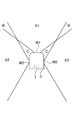
図1Aは、一実施形態の内視鏡の先端部Tに設けられた前方窓W1及び側方窓W2から見える視野範囲の一例を説明する図である。側方窓W2は、筒状の先端部Tの外周に沿って一周するように設けられる。前方窓W1は、先端部Tに設けられる撮像素子Iの受光面の前方に設けられ、受光面の前方方向(図1Aでは上方向)の領域を、対物レンズを通して見ることができる窓であり、側方窓W2は、撮像素子Iの受光面の前方に設けられ、前方と直交する方向(図1Aに示す横方向)の領域を、対物レンズを通して見ることができる窓である。本実施形態における側方窓W2は、前方と直交する側方に向く窓であるが、前方窓W1に比べて側方の側に向いていればよい。側方窓W2の向きは(側方窓W2から見える視野範囲の中心軸の向く方向)は、前方に対して例えば30度~90度傾斜していればよい。
前方窓W1及び先端部Tに設けられた図示されない対物レンズを通して見える視野範囲には、領域A1及び領域Bがあり、側方窓W2及び先端部Tに設けられた図示されない対物レンズを通して見える視野範囲には、領域A2及び領域Bがある。領域Bは、前方窓W1から見える視野範囲と側方窓W2から見える視野範囲に重複するので、以降、領域Bは重複領域Bという。
一方、前方窓W1及び側方窓W2から見える視野範囲には、図示される領域Cは含まれない。すなわち、領域Cにある被写体は、いずれの視野範囲にも含まれないので、撮像素子Iによる撮像画像には映らない。以降、領域Cは死角領域Cという。 FIG. 1A is a diagram illustrating an example of a visual field range that can be seen from a front window W1 and a side window W2 provided at the tip end portion T of the endoscope of one embodiment. The side window W2 is provided so as to go around the outer circumference of the cylindrical tip portion T. The front window W1 is provided in front of the light receiving surface of the image sensor I provided at the tip portion T, and is a window through which the region in the front direction (upward in FIG. 1A) of the light receiving surface can be seen through the objective lens. The side window W2 is provided in front of the light receiving surface of the image sensor I, and is a window through which the region in the direction orthogonal to the front (lateral direction shown in FIG. 1A) can be seen through the objective lens. The side window W2 in the present embodiment is a window facing sideways orthogonal to the front, but it may be facing sideways as compared with the front window W1. The direction of the side window W2 (the direction in which the central axis of the visual field range seen from the side window W2 faces) may be inclined, for example, 30 degrees to 90 degrees with respect to the front.
The visual field range that can be seen through the objective lens (not shown) provided in the front window W1 and the tip portion T includes the area A1 and the region B, and the visual field range that can be seen through the objective lens (not shown) provided in the side window W2 and the tip portion T. Has a region A2 and a region B. Since the area B overlaps the field of view seen from the front window W1 and the field of view seen from the side window W2, the area B is hereinafter referred to as the overlapping area B.
On the other hand, the visual field range seen from the front window W1 and the side window W2 does not include the illustrated region C. That is, since the subject in the region C is not included in any of the visual field ranges, it is not reflected in the image captured by the image sensor I. Hereinafter, the area C is referred to as a blind spot area C.
図1Bは、器官内における内視鏡の先端部Tの横方向の位置の一例と、そのときの視野範囲の左右方向の違いを説明する図である。図1Bに示すように、先端部Tの器官内における横方向の位置によって、器官内の生体組織表面の視野範囲が異なる。図1B中の右側の前方窓W1及び側方窓W2から見える全体の視野範囲は、領域A1、重複領域B、及び領域A2を含む。図1B中の左側の前方窓W1及び側方窓W2から見える全体の視野範囲は、先端部Tが器官内で左方向に偏って位置しているので、領域A1、及び領域A2を含み、死角領域Cを含まない。したがって、撮像素子Iの視野範囲には、死角領域Cがある。
FIG. 1B is a diagram for explaining an example of the lateral position of the tip T of the endoscope in the organ and the difference in the visual field range in the left-right direction at that time. As shown in FIG. 1B, the visual field range of the surface of the living tissue in the organ differs depending on the lateral position of the tip T in the organ. The entire visual field range seen from the right front window W1 and the side window W2 in FIG. 1B includes the area A1, the overlapping area B, and the area A2. The entire visual field range seen from the left front window W1 and the side window W2 in FIG. 1B includes the area A1 and the area A2 because the tip T is biased to the left in the organ, and is a blind spot. Does not include region C. Therefore, there is a blind spot region C in the visual field range of the image sensor I.
図1Bに示す例では、右側の視野範囲において、重複領域Bがあることから、重複領域Bに他の部分と異なる色彩を有する特徴部分、例えば病変部がある場合、病変部は、前方窓W1から見える視野範囲にあり、かつ、側方窓W2から見える視野範囲にある。このため、撮像素子Iは、前方窓W1から見える特徴部分の像と側方窓W2から見える特徴部分の像とを、対物レンズを通して1つの画像として撮像することができる。
In the example shown in FIG. 1B, since there is an overlapping region B in the visual field range on the right side, when the overlapping region B has a characteristic portion having a different color from the other portions, for example, a lesion portion, the lesion portion is the anterior window W1. It is in the visual field range that can be seen from the side window W2 and is in the visual field range that can be seen from the side window W2. Therefore, the image sensor I can image the image of the feature portion seen from the front window W1 and the image of the feature portion seen from the side window W2 as one image through the objective lens.
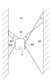
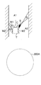
図2Aは、特徴部分Sの、前方窓W1及び側方窓W2から見た特徴部分Sへの視線方向を説明する図である。図2Bは、図2Aに示す特徴部分Sの撮像画像の一例を示す図である。
図2A,図2Bには、前方窓W1の窓中心を通り、窓表面の法線方向に延びる中心軸Ax1、及び、側方窓W2の窓幅の窓中心を通り、窓表面の法線方向に延びる中心軸Ax2を示している。中心軸Ax1は、後述する対物レンズの光軸の延長線上にあるので、撮像画像では点として現れる。一方、側方窓W2は、筒状の先端部Tの周上を一周するように設けられるので、撮像画像では、円周形状として現れる。
図2Aに示すように、特徴部分Sは、重複領域Bにあるので、特徴部分Sの像は、図2Bに示すように、撮像画像において2つ現れる。撮像画像において、特徴部分Sの像が2つ現れると、3次元拡張処理部は、即座に2つの特徴部分Sの像から、特徴部分Sへの視線V1,V2を用いて、三角測量の原理により奥行方向(前方)の位置情報を求める。
なお、前方窓W1と側方窓W2から見た奥行方向は、図2Aに示す例では、上方向ではなく、上方向から横方向に傾斜した傾斜方向であり、特徴部分Sへの視線V1,V2を用いて、例えば前方窓W1の窓中心から特徴部分Sまでの距離と方向を求めることができる。したがって、特徴部分Sの距離と方向を用いて、特徴部分Sと非特徴部分の境界部分を基準とした特徴部分Sの器官内の表面からの高さ方向の位置情報を求めることができる。また、前方窓W1の窓中心から特徴部分Sまでの前方方向(図2Aでは上方向)の位置情報を求めることもできる。
このように、3次元拡張処理部は、特徴部分Sが重複領域Bに入って、特徴部分Sの像が2つ現れると、即座に上記3次元情報を求めて、特徴部分Sの、生体組織の表面から突出する高さ方向の位置情報を含み、さらに、特徴部分Sの、前方方向の位置情報を含む3次元位置情報を即座に求める。 FIG. 2A is a diagram for explaining the line-of-sight direction of the feature portion S from the front window W1 and the side window W2 to the feature portion S. FIG. 2B is a diagram showing an example of a captured image of the feature portion S shown in FIG. 2A.
2A and 2B show the central axis Ax1 extending in the normal direction of the window surface passing through the window center of the front window W1 and the window center of the window width of the side window W2 in the normal direction of the window surface. The central axis Ax2 extending to is shown. Since the central axis Ax1 is on an extension line of the optical axis of the objective lens described later, it appears as a point in the captured image. On the other hand, since the side window W2 is provided so as to go around the circumference of the cylindrical tip portion T, it appears as a circumferential shape in the captured image.
As shown in FIG. 2A, since the feature portion S is in the overlapping region B, two images of the feature portion S appear in the captured image as shown in FIG. 2B. When two images of the feature portion S appear in the captured image, the three-dimensional expansion processing unit immediately uses the lines of sight V1 and V2 from the two images of the feature portion S to the feature portion S to perform the principle of triangulation. The position information in the depth direction (forward) is obtained by.
In the example shown in FIG. 2A, the depth direction seen from the front window W1 and the side window W2 is not an upward direction but an inclined direction inclined from the upper direction to the lateral direction, and the line of sight V1 to the feature portion S Using V2, for example, the distance and direction from the window center of the front window W1 to the feature portion S can be obtained. Therefore, using the distance and direction of the feature portion S, it is possible to obtain the position information in the height direction from the surface of the feature portion S in the organ with reference to the boundary portion between the feature portion S and the non-feature portion. Further, it is also possible to obtain the position information in the front direction (upward in FIG. 2A) from the window center of the front window W1 to the feature portion S.
As described above, the three-dimensional expansion processing unit immediately obtains the above-mentioned three-dimensional information when the feature portion S enters the overlapping region B and two images of the feature portion S appear, and the biological tissue of the feature portion S. The three-dimensional position information including the position information in the height direction protruding from the surface of the feature portion S and the position information in the front direction of the feature portion S is immediately obtained.
内視鏡の先端部は、図2Aに例では、下方向に移動しながら、例えば器官内の生体組織の表面を撮像するので、図2Aに示す特徴部分Sが重複領域Bに位置する状態になる前に、特徴部分Sは、側方窓W2の視野範囲の領域A2に位置し、撮像画像において1つしか現れない。この後、図2Bに示すように特徴部分Sの2つの像が撮像画像に現れる。図2Bに示す例では、撮像画像は、視野範囲が円形状であることを考慮して円形状の例を示しているが、モニタでは、円形状の一部を切り欠いた矩形形状の表示画面で表示されてもよい。その後、特徴部分Sは、領域A1に位置するので、特徴部分Sの像は撮像画像において1つになる。
したがって、特徴部分Sが重複領域Bに位置して特徴部分Sの像が2つ撮像画像に現れる場合、重複領域Bを無くし、器官内の表面を、あたかも領域A1、重複領域B、及び領域A2を、1つの窓、例えば前方窓W1を通して見た画像を作成することができる。しかも、特徴部分Sの像が2つ現れると、即座に3次元情報を求めることができるので、特徴部分Sの像をモニタに表示するとき、3次元情報を画像に反映する、すなわち3次元画像にすることができる。例えば、特徴部分Sの高さ方向の情報が得られるので、特徴部分Sを周りの部分に対する表面凹凸を再現するレンダリング処理を行うこともできる。 In the example shown in FIG. 2A, the tip of the endoscope images the surface of a living tissue in an organ while moving downward, so that the feature portion S shown in FIG. 2A is located in the overlapping region B. Before this, the feature portion S is located in the region A2 of the visual field range of the side window W2, and only one of the feature portions S appears in the captured image. After that, as shown in FIG. 2B, two images of the feature portion S appear in the captured image. In the example shown in FIG. 2B, the captured image shows an example of a circular shape in consideration of the fact that the field of view is circular, but on the monitor, a rectangular display screen in which a part of the circular shape is cut out is shown. It may be displayed as. After that, since the feature portion S is located in the region A1, the image of the feature portion S becomes one in the captured image.
Therefore, when the feature portion S is located in the overlap region B and two images of the feature portion S appear in the captured image, the overlap region B is eliminated and the surface in the organ is treated as if the region A1, the overlap region B, and the region A2. Can be created as an image viewed through one window, for example, the front window W1. Moreover, when two images of the feature portion S appear, the three-dimensional information can be obtained immediately. Therefore, when the image of the feature portion S is displayed on the monitor, the three-dimensional information is reflected in the image, that is, the three-dimensional image. Can be. For example, since the information in the height direction of the feature portion S can be obtained, it is possible to perform a rendering process for reproducing the surface unevenness of the feature portion S with respect to the surrounding portion.
なお、上述した3次元情報に拡張する処理は、前方窓W1及び側方窓W2から見える特徴部分Sへの視線方向の情報を用いて行うが、必ずしも前方窓W1及び側方窓W2に限定されず、三角測量の原理が適用できる限りにおいて、異なる位置に設けられた複数の窓であってもよい。例えば、先端部Tの先端面に、複数の窓が設けられてもよい。さらに、三角測量の原理が適用できる限りにおいて、先端部Tを例えば器官内で移動させたときの異なる撮像位置で撮像された2つ以上の撮像画像であって、特徴部分Sの像が共通して現れている撮像画像を用いて、3次元情報に拡張する処理を行ってもよい。この場合、3次元情報に拡張する処理を行うために、撮像位置の情報であって、少なくとも撮像位置間の距離情報を取得することが好ましい。これにより、同じ特徴部分Sの視線の方向と取得した距離情報とを用いて、3次元情報を求めることができる。
なお、3次元情報をより正確に求めるために、3つ以上の窓から見た撮像画像、あるいは3つ以上の撮像位置における撮像画像を用いてもよい。この場合、情報が過多になるので、三角測量の原理で3次元情報を求めるとき、計算誤差が最小となるように計算することが好ましい。 The process of expanding to the above-mentioned three-dimensional information is performed using the information in the line-of-sight direction to the feature portion S seen from the front window W1 and the side window W2, but is not necessarily limited to the front window W1 and the side window W2. However, as long as the principle of triangulation can be applied, a plurality of windows provided at different positions may be used. For example, a plurality of windows may be provided on the tip surface of the tip portion T. Further, as long as the principle of triangulation can be applied, the images of the feature portion S are common to two or more captured images taken at different imaging positions when the tip portion T is moved in the organ, for example. A process of expanding to three-dimensional information may be performed using the captured image appearing in the above. In this case, in order to perform the process of expanding to three-dimensional information, it is preferable to acquire at least the distance information between the imaging positions, which is the information of the imaging position. Thereby, the three-dimensional information can be obtained by using the direction of the line of sight of the same feature portion S and the acquired distance information.
In addition, in order to obtain the three-dimensional information more accurately, the captured image viewed from three or more windows or the captured image at three or more imaging positions may be used. In this case, since the amount of information becomes excessive, it is preferable to perform the calculation so that the calculation error is minimized when the three-dimensional information is obtained by the principle of triangulation.
(内視鏡システムの具体的な形態)
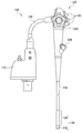
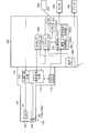
図3は、一実施形態の内視鏡の外観斜視図である。図4は、一実施形態の内視鏡システムの構成を示すブロック図である。図4は、一実施形態の内視鏡の先端部の構成の一例を示す図である。 (Specific form of endoscopic system)
FIG. 3 is an external perspective view of the endoscope of one embodiment. FIG. 4 is a block diagram showing the configuration of the endoscope system of one embodiment. FIG. 4 is a diagram showing an example of the configuration of the tip portion of the endoscope of one embodiment.
図3に示す内視鏡(以降、電子スコープという)100は、図4に示す電子内視鏡用のプロセッサ200に接続されて内視鏡システム1を形成する。内視鏡システム1は、医療用に特化されたシステムであり、図4に示すように、電子スコープ100、電子内視鏡用のプロセッサ200、及びモニタ300、を主に備える。電子スコープ100及びモニタ300は、それぞれプロセッサ200に接続される。
The endoscope (hereinafter referred to as an electronic scope) 100 shown in FIG. 3 is connected to the processor 200 for the electronic endoscope shown in FIG. 4 to form the endoscope system 1. The endoscope system 1 is a system specialized for medical use, and as shown in FIG. 4, mainly includes an electronic scope 100, a processor 200 for an electronic endoscope, and a monitor 300. The electron scope 100 and the monitor 300 are connected to the processor 200, respectively.
電子スコープ100は、図3に示すように、コネクタ110、操作部120、及び先端部132を主に備え、さらに、操作部120から前方の先端部132に向かって延びかつ可撓性を有する可撓性ケーブル130と、可撓性ケーブル130の前方に連結部を介して連結され、自在に湾曲する湾曲管134と、操作部120から後方に延びるユニバーサルチューブ128とを備える。コネクタ110は、ユニバーサルチューブ128の後端に固定され、プロセッサ200と接続されるように構成されている。
操作部120、可撓性ケーブル130及び湾曲管134内には、複数の湾曲操作ワイヤが挿通され、各湾曲操作ワイヤの先端は、湾曲管134の後端に連結され、各湾曲操作ワイヤの後端は、操作部120の湾曲操作ノブ122に連結されている。湾曲管134は、湾曲操作ノブ122の操作に応じて任意の方向に任意の角度だけ湾曲する。 As shown in FIG. 3, theelectron scope 100 mainly includes a connector 110, an operation unit 120, and a tip portion 132, and can extend from the operation unit 120 toward the front tip portion 132 and have flexibility. The flexible cable 130 includes a curved tube 134 that is connected to the front of the flexible cable 130 via a connecting portion and bends freely, and a universal tube 128 that extends rearward from the operating portion 120. The connector 110 is fixed to the rear end of the universal tube 128 and is configured to be connected to the processor 200.
A plurality of bending operation wires are inserted into theoperation unit 120, the flexible cable 130, and the bending tube 134, and the tip of each bending operation wire is connected to the rear end of the bending tube 134 to be rear of each bending operation wire. The end is connected to the curved operation knob 122 of the operation unit 120. The curved pipe 134 is curved in an arbitrary direction by an arbitrary angle according to the operation of the bending operation knob 122.
操作部120、可撓性ケーブル130及び湾曲管134内には、複数の湾曲操作ワイヤが挿通され、各湾曲操作ワイヤの先端は、湾曲管134の後端に連結され、各湾曲操作ワイヤの後端は、操作部120の湾曲操作ノブ122に連結されている。湾曲管134は、湾曲操作ノブ122の操作に応じて任意の方向に任意の角度だけ湾曲する。 As shown in FIG. 3, the
A plurality of bending operation wires are inserted into the
さらに、操作部120は、複数の操作ボタン124を備える。操作ボタン124は、内視鏡操作者(術者又は補助者)が操作ボタン124を押すことにより、先端部132の先端面に設けられた図示されない送気送水口からの水や気体の吐出、吸引口による生体組織にある液体や気体の吸引、及び対物レンズの洗浄のための洗浄液吐出ノズルからの洗浄液の吐出等の各機能を指示することができる。操作ボタン124を押すことにより機能させたい動作を予め定めて、操作ボタン124にその動作を実施させる機能を割り当てることができる。
Further, the operation unit 120 includes a plurality of operation buttons 124. The operation button 124 is such that when the endoscope operator (operator or assistant) presses the operation button 124, water or gas is discharged from an air supply / water supply port (not shown) provided on the tip surface of the tip portion 132. It is possible to instruct each function such as suction of a liquid or gas in a living tissue by a suction port and discharge of a cleaning liquid from a cleaning liquid discharge nozzle for cleaning an objective lens. By pressing the operation button 124, the operation to be performed can be determined in advance, and the operation button 124 can be assigned a function to execute the operation.
湾曲管134の先端にある先端部132は実質的に弾性変形しない硬質樹脂材料(例えば、ABS、変性PPO、PSUなど)によって構成されている。
先端部132の内部には、LED光源102と、対物レンズ106の直後に位置する撮像素子108と、が設けられている。すなわち、長尺状の可撓性ケーブル130の先端に設けられた先端部132は、LED光源102、対物レンズ106、及び撮像素子108を備える。対物レンズ106は、撮像素子108の前面に設けられ、撮像素子108の受光面に生体組織の像を、視野角180度以上、好ましくは180度超の視野範囲で結像させる。先端部132には、後述するように、撮像素子108の受光面の前方に向いた前方窓と、前方に対して直交する側方に向いた側方窓が設けられ、前方窓及び側方窓を通して、対物レンズ106により受光面に結像した像を、撮像素子108は撮像するように構成されている。 Thetip 132 at the tip of the curved tube 134 is made of a hard resin material (eg, ABS, modified PPO, PSU, etc.) that does not substantially elastically deform.
Inside thetip 132, an LED light source 102 and an image sensor 108 located immediately after the objective lens 106 are provided. That is, the tip portion 132 provided at the tip of the long flexible cable 130 includes the LED light source 102, the objective lens 106, and the image pickup element 108. The objective lens 106 is provided on the front surface of the image pickup element 108, and an image of living tissue is formed on the light receiving surface of the image pickup element 108 in a viewing angle of 180 degrees or more, preferably more than 180 degrees. As will be described later, the tip portion 132 is provided with a front window facing forward of the light receiving surface of the image sensor 108 and a side window facing side orthogonal to the front, and the front window and the side window. The image sensor 108 is configured to take an image of an image formed on the light receiving surface by the objective lens 106.
先端部132の内部には、LED光源102と、対物レンズ106の直後に位置する撮像素子108と、が設けられている。すなわち、長尺状の可撓性ケーブル130の先端に設けられた先端部132は、LED光源102、対物レンズ106、及び撮像素子108を備える。対物レンズ106は、撮像素子108の前面に設けられ、撮像素子108の受光面に生体組織の像を、視野角180度以上、好ましくは180度超の視野範囲で結像させる。先端部132には、後述するように、撮像素子108の受光面の前方に向いた前方窓と、前方に対して直交する側方に向いた側方窓が設けられ、前方窓及び側方窓を通して、対物レンズ106により受光面に結像した像を、撮像素子108は撮像するように構成されている。 The
Inside the
可撓性ケーブル130、湾曲管134、及び先端部132は、体腔内に挿入される挿入部135を形成する。先端部132に設けられた撮像素子108から延びる画像信号用ケーブルは、先端部132から、湾曲管134、可撓性ケーブル130、さらに、操作部120及びユニバーサルチューブ128の内部を通ってコネクタ110の内部まで延びている。コネクタ110は、プロセッサ200に接続される。プロセッサ200は、撮像素子から送られてくる画像信号を処理して、撮像素子108で撮像した被写体の画像をモニタ300に表示するように制御している。
The flexible cable 130, the curved tube 134, and the tip portion 132 form an insertion portion 135 to be inserted into the body cavity. The image signal cable extending from the image sensor 108 provided at the tip 132 passes through the inside of the curved tube 134, the flexible cable 130, the operation section 120, and the universal tube 128 from the tip 132 of the connector 110. It extends to the inside. The connector 110 is connected to the processor 200. The processor 200 processes the image signal sent from the image sensor and controls the monitor 300 to display the image of the subject captured by the image sensor 108.
図4に示すように内視鏡システム1のプロセッサ200は、システムコントローラ202及びタイミングコントローラ206を備えている。システムコントローラ202は、メモリ204に記憶された各種プログラムを実行し、電子内視鏡システム1の全体を統括的に制御する。また、システムコントローラ202は、操作パネル208に入力される内視鏡操作者(術者又は補助者)による指示に応じて電子内視鏡システム1の各種設定を変更する。タイミングコントローラ206は、各部の動作のタイミングを調整するクロックパルスを電子内視鏡システム1内の各回路に出力する。
As shown in FIG. 4, theprocessor 200 of the endoscope system 1 includes a system controller 202 and a timing controller 206. The system controller 202 executes various programs stored in the memory 204 and controls the entire electronic endoscopy system 1 in an integrated manner. Further, the system controller 202 changes various settings of the electronic endoscope system 1 according to an instruction by the endoscope operator (operator or assistant) input to the operation panel 208. The timing controller 206 outputs a clock pulse for adjusting the operation timing of each part to each circuit in the electronic endoscope system 1.
As shown in FIG. 4, the
電子スコープ100の先端部132には、撮像素子108の他にLED光源102が設けられている。LED光源102は、撮像素子108による撮像のために、生体組織を照明する照明光を出射する。
LED光源102は、コネクタ110に設けられた光源制御回路116で生成される駆動信号により駆動されて光を出射する。LED光源102の替わりに、レーザ素子を用いてもよく、また、高輝度ランプ、例えば、キセノンランプ、メタルハライドランプ、水銀ランプ又はハロゲンランプを用いてもよい。
図4に示す例では、LED光源102が、先端部132に設けられるが、コネクタ110あるいはプロセッサ200に光源装置として設けられてもよい。この場合、光源装置から先端部132まで、照明光は、ファイバケーブルを複数本束ねたライトガイドを通して先端部132に導かれる。 Thetip 132 of the electron scope 100 is provided with an LED light source 102 in addition to the image sensor 108. The LED light source 102 emits illumination light that illuminates the living tissue for imaging by the image sensor 108.
The LEDlight source 102 is driven by a drive signal generated by the light source control circuit 116 provided in the connector 110 to emit light. Instead of the LED light source 102, a laser element may be used, or a high-brightness lamp such as a xenon lamp, a metal halide lamp, a mercury lamp or a halogen lamp may be used.
In the example shown in FIG. 4, the LEDlight source 102 is provided at the tip portion 132, but may be provided at the connector 110 or the processor 200 as a light source device. In this case, from the light source device to the tip 132, the illumination light is guided to the tip 132 through a light guide in which a plurality of fiber cables are bundled.
LED光源102は、コネクタ110に設けられた光源制御回路116で生成される駆動信号により駆動されて光を出射する。LED光源102の替わりに、レーザ素子を用いてもよく、また、高輝度ランプ、例えば、キセノンランプ、メタルハライドランプ、水銀ランプ又はハロゲンランプを用いてもよい。
図4に示す例では、LED光源102が、先端部132に設けられるが、コネクタ110あるいはプロセッサ200に光源装置として設けられてもよい。この場合、光源装置から先端部132まで、照明光は、ファイバケーブルを複数本束ねたライトガイドを通して先端部132に導かれる。 The
The LED
In the example shown in FIG. 4, the LED
LED光源102から出射した光は、照明光として、配光レンズ104を介して被写体である生体組織に照射される。生体組織からの反射光は、前方窓140及び側方窓150(図3参照)及び対物レンズ106を通して撮像素子108の受光面上で光学像を結ぶ。
The light emitted from the LED light source 102 is irradiated to the living tissue as the subject through the light distribution lens 104 as illumination light. The reflected light from the living tissue forms an optical image on the light receiving surface of the image sensor 108 through the front window 140, the side window 150 (see FIG. 3), and the objective lens 106.
撮像素子108は、例えば、IR(Infrared)カットフィルタ108a、ベイヤ配列のカラーフィルタ108bの各種フィルタが受光面に配置された単板式カラーCCD(Charge-Coupled Device)イメージセンサであり、受光面上で結像した光学像に応じたR(Red)、G(Green)、B(Blue)の各原色信号を生成する。単板式カラーCCDイメージセンサの代わりに、単板式カラーCMOS(Complementary Metal Oxide Semiconductor)イメージセンサを用いることもできる。このように、電子スコープ100は、撮像素子108を用いて、器官内部の生体組織を撮像し、動画を生成する。
The image sensor 108 is, for example, a single-plate color CCD (Charge-Coupled Device) image sensor in which various filters of an IR (Infrared) cut filter 108a and a Bayer-arranged color filter 108b are arranged on a light receiving surface, and is on the light receiving surface. Each primary color signal of R (Red), G (Green), and B (Blue) corresponding to the imaged optical image is generated. Instead of the single-plate color CCD image sensor, a single-plate color CMOS (Complementary Metal Oxide Semiconductor) image sensor can also be used. In this way, the electron scope 100 uses the image sensor 108 to image the biological tissue inside the organ and generate a moving image.
電子スコープ100のコネクタ110の内部には、ドライバ信号処理回路112が備えられている。ドライバ信号処理回路112は、撮像素子108より入力される原色信号に対して色補間、マトリックス演算等の所定の信号処理を施して画像信号(輝度信号Y、色差信号Cb,Cr)を生成し、生成された画像信号を電子内視鏡用プロセッサ200の画像処理ユニット220に出力する。また、ドライバ信号処理回路112は、メモリ114にアクセスして電子スコープ100の固有情報を読み出す。メモリ114に記録される電子スコープ100の固有情報には、例えば撮像素子108の画素数や感度、動作可能なフレームレート、型番等が含まれる。ドライバ信号処理回路112は、メモリ114より読み出された固有情報をシステムコントローラ202に出力する。
A driver signal processing circuit 112 is provided inside the connector 110 of the electronic scope 100. The driver signal processing circuit 112 performs predetermined signal processing such as color interpolation and matrix calculation on the primary color signal input from the image pickup element 108 to generate an image signal (brightness signal Y, color difference signal Cb, Cr). The generated image signal is output to the image processing unit 220 of the electronic endoscope processor 200. Further, the driver signal processing circuit 112 accesses the memory 114 and reads out the unique information of the electronic scope 100. The unique information of the electronic scope 100 recorded in the memory 114 includes, for example, the number of pixels and sensitivity of the image sensor 108, the frame rate that can be operated, the model number, and the like. The driver signal processing circuit 112 outputs the unique information read from the memory 114 to the system controller 202.
システムコントローラ202は、メモリ204に記憶された情報及び電子スコープ100の固有情報に基づいて各種演算を行い、制御信号を生成する。システムコントローラ202は、生成された制御信号を用いて、電子内視鏡用プロセッサ200に接続中の電子スコープ100に適した処理がなされるように電子内視鏡用プロセッサ200内の各回路の動作やタイミングを制御する。
The system controller 202 performs various operations based on the information stored in the memory 204 and the unique information of the electronic scope 100, and generates a control signal. The system controller 202 uses the generated control signal to operate each circuit in the electronic endoscope processor 200 so that processing suitable for the electronic scope 100 connected to the electronic endoscope processor 200 is performed. And control the timing.
タイミングコントローラ206は、システムコントローラ202によるタイミング制御に従って、ドライバ信号処理回路112、画像処理ユニット220、及び光源部230にクロックパルスを供給する。ドライバ信号処理回路112は、タイミングコントローラ206から供給されるクロックパルスに従って、撮像素子108を電子内視鏡用プロセッサ200側で処理される映像のフレームレートに同期したタイミングで駆動制御する。
The timing controller 206 supplies clock pulses to the driver signal processing circuit 112, the image processing unit 220, and the light source unit 230 according to the timing control by the system controller 202. The driver signal processing circuit 112 drives and controls the image pickup element 108 at a timing synchronized with the frame rate of the image processed on the electronic endoscope processor 200 side according to the clock pulse supplied from the timing controller 206.
画像処理ユニット220は、システムコントローラ202による制御の下、ドライバ信号処理回路112より入力した画像信号に基づいて画像等をモニタ表示するためのビデオ信号を生成し、モニタ300に出力する画像処理部220A(図4参照)を有する。
画像処理ユニット220は、さらに、撮像素子108による撮像画像中の特徴部分の像の2次元情報を3次元情報に拡張するように構成された3次元拡張処理部220B(図4参照)を備える。3次元拡張処理部220Bについては後述する。 また、画像処理部220Aは、電子スコープ100で得られた生体組織の画像に対して、病変部を健常部と区別できる画像の各画素の特徴量を数値化する数値化処理を行い、画像の病変部の進行の程度を評価し、さらに、数値化処理によって得られた各画素の数値を色に置換したカラーマップ画像を生成してもよい。この場合、画像処理部220Aは、数値化処理の結果の情報とカラーマップ画像をモニタ表示するためのビデオ信号を生成し、モニタ300に出力する。これにより、内視鏡操作者は、モニタ300の表示画面に表示された画像を通じて検査を精度よく行うことができる。画像処理部220Aは、必要に応じてプリンタ400に画像、数値化処理の結果の情報、及びカラーマップ画像を出力する。 Under the control of thesystem controller 202, the image processing unit 220 generates a video signal for displaying an image or the like on a monitor based on the image signal input from the driver signal processing circuit 112, and outputs the image processing unit 220A to the monitor 300. (See FIG. 4).
Theimage processing unit 220 further includes a three-dimensional expansion processing unit 220B (see FIG. 4) configured to expand the two-dimensional information of the image of the feature portion in the image captured by the image pickup element 108 to the three-dimensional information. The three-dimensional expansion processing unit 220B will be described later. Further, the image processing unit 220A performs a quantification process on the image of the living tissue obtained by the electron scope 100 to quantify the feature amount of each pixel of the image that can distinguish the lesion part from the healthy part. The degree of progression of the lesion may be evaluated, and a color map image may be generated in which the numerical value of each pixel obtained by the digitization process is replaced with a color. In this case, the image processing unit 220A generates information on the result of the digitization processing and a video signal for displaying the color map image on the monitor, and outputs the video signal to the monitor 300. As a result, the endoscope operator can accurately perform the inspection through the image displayed on the display screen of the monitor 300. The image processing unit 220A outputs an image, information on the result of digitization processing, and a color map image to the printer 400 as needed.
画像処理ユニット220は、さらに、撮像素子108による撮像画像中の特徴部分の像の2次元情報を3次元情報に拡張するように構成された3次元拡張処理部220B(図4参照)を備える。3次元拡張処理部220Bについては後述する。 また、画像処理部220Aは、電子スコープ100で得られた生体組織の画像に対して、病変部を健常部と区別できる画像の各画素の特徴量を数値化する数値化処理を行い、画像の病変部の進行の程度を評価し、さらに、数値化処理によって得られた各画素の数値を色に置換したカラーマップ画像を生成してもよい。この場合、画像処理部220Aは、数値化処理の結果の情報とカラーマップ画像をモニタ表示するためのビデオ信号を生成し、モニタ300に出力する。これにより、内視鏡操作者は、モニタ300の表示画面に表示された画像を通じて検査を精度よく行うことができる。画像処理部220Aは、必要に応じてプリンタ400に画像、数値化処理の結果の情報、及びカラーマップ画像を出力する。 Under the control of the
The
プロセッサ200は、NIC(Network Interface Card)210及びネットワーク500を介してサーバ600に接続されている。プロセッサ200は、内視鏡による検査に関する情報(例えば、患者の電子カルテ情報や術者の情報)をサーバ600からダウンロードすることができる。ダウンロードされた情報は、例えばモニタ300の表示画面や操作パネル208に表示される。また、プロセッサ200は、電子スコープ100による検査結果をサーバ600にアップロードすることにより、検査結果をサーバ600に保存させることができる。
The processor 200 is connected to the server 600 via the NIC (Network Interface Card) 210 and the network 500. The processor 200 can download information related to the endoscopic examination (for example, patient electronic medical record information and operator information) from the server 600. The downloaded information is displayed, for example, on the display screen of the monitor 300 or the operation panel 208. Further, the processor 200 can save the inspection result in the server 600 by uploading the inspection result by the electronic scope 100 to the server 600.
図5は、先端部132の内部構造の一例を説明する図である。
先端部132は、対物レンズ106、撮像素子108、前方窓140、及び側方窓150を備える。対物レンズ106及び撮像素子108は、先端部132の硬質樹脂材料で形成された筒部材133に配置されている。先端部132は、図1A,図1B及び図2Aに示す例おける先端部Tに対応する。
前方窓140は、撮像素子108の受光面108cの前方向に向いている。側方窓150は、前方に対して直交する側方に向いている。側方窓150は、前方に対して直交する側方に向いているが、上述したように、側方窓150は、前方窓140に比べて側方の側に向いていればよい。
対物レンズ106は、メニスカスレンズ、凸レンズ、及び凹レンズを含むレンズ106a~106eのレンズ群で構成されて、半画角は90度超、好ましくは110度以上となっている。したがって、対物レンズ106は、前方窓140を通して得られる生体組織の直視像と、側方窓150を通して得られる生体組織の側視像とを、撮像画像として同時に受光面108cに結像させる。レンズ106aの被写体側の表面は、前方窓140を兼ねている。側方窓150には、カバーガラスが設けられている。 FIG. 5 is a diagram illustrating an example of the internal structure of thetip portion 132.
Thetip 132 includes an objective lens 106, an image sensor 108, a front window 140, and a side window 150. The objective lens 106 and the image sensor 108 are arranged on the tubular member 133 formed of the hard resin material at the tip portion 132. The tip 132 corresponds to the tip T in the examples shown in FIGS. 1A, 1B and 2A.
Thefront window 140 faces the front direction of the light receiving surface 108c of the image sensor 108. The side window 150 faces sideways orthogonal to the front. The side window 150 faces the side orthogonal to the front, but as described above, the side window 150 may face the side side with respect to the front window 140.
Theobjective lens 106 is composed of a lens group of lenses 106a to 106e including a meniscus lens, a convex lens, and a concave lens, and has a half angle of view of more than 90 degrees, preferably 110 degrees or more. Therefore, the objective lens 106 simultaneously forms an image of the direct view image of the living tissue obtained through the front window 140 and the side view image of the living tissue obtained through the side window 150 on the light receiving surface 108c as an image. The surface of the lens 106a on the subject side also serves as the front window 140. A cover glass is provided on the side window 150.
先端部132は、対物レンズ106、撮像素子108、前方窓140、及び側方窓150を備える。対物レンズ106及び撮像素子108は、先端部132の硬質樹脂材料で形成された筒部材133に配置されている。先端部132は、図1A,図1B及び図2Aに示す例おける先端部Tに対応する。
前方窓140は、撮像素子108の受光面108cの前方向に向いている。側方窓150は、前方に対して直交する側方に向いている。側方窓150は、前方に対して直交する側方に向いているが、上述したように、側方窓150は、前方窓140に比べて側方の側に向いていればよい。
対物レンズ106は、メニスカスレンズ、凸レンズ、及び凹レンズを含むレンズ106a~106eのレンズ群で構成されて、半画角は90度超、好ましくは110度以上となっている。したがって、対物レンズ106は、前方窓140を通して得られる生体組織の直視像と、側方窓150を通して得られる生体組織の側視像とを、撮像画像として同時に受光面108cに結像させる。レンズ106aの被写体側の表面は、前方窓140を兼ねている。側方窓150には、カバーガラスが設けられている。 FIG. 5 is a diagram illustrating an example of the internal structure of the
The
The
The
先端部132の前方窓140及び側方窓150から見える視野範囲は、図1Aに示すように、領域A1、重複領域B、領域A2を含む。さらに、前方窓140及び側方窓150から被写体が見えない死角領域Cがある。生体組織の像は、前方窓140を通して得られる直視像と側方窓150を通して得られる側視像とを同時に撮像するので、撮像画像には、図2Bに示すように特徴部分Sが2つの像として現れる場合がある。
画像処理ユニット220は、この撮像画像に現れる2つの特徴部分Sの像の2次元情報(撮像画像上のx座標位置及びy座標位置)から特徴部分Sの3次元情報を求める3次元拡張処理部220Bを備える。 As shown in FIG. 1A, the viewing range seen from thefront window 140 and the side window 150 of the tip portion 132 includes the area A1, the overlapping area B, and the area A2. Further, there is a blind spot region C in which the subject cannot be seen from the front window 140 and the side window 150. Since the image of the living tissue simultaneously captures the direct view image obtained through the front window 140 and the side view image obtained through the side window 150, the captured image has two characteristic portions S as shown in FIG. 2B. May appear as.
Theimage processing unit 220 is a three-dimensional expansion processing unit that obtains three-dimensional information of the feature portion S from the two-dimensional information (x-coordinate position and y-coordinate position on the captured image) of the images of the two feature portions S appearing in the captured image. It is equipped with 220B.
画像処理ユニット220は、この撮像画像に現れる2つの特徴部分Sの像の2次元情報(撮像画像上のx座標位置及びy座標位置)から特徴部分Sの3次元情報を求める3次元拡張処理部220Bを備える。 As shown in FIG. 1A, the viewing range seen from the
The
3次元拡張処理部220Bは、電子スコープ100が撮像した撮像画像内の前方窓140及び側方窓150を通して得られる2つの像(直視像及び側視像)それぞれに共通して含まれる2つの特徴部分Sの像それぞれにおける位置情報に基づいて、前方窓140及び側方窓150を通して見える特徴部分Sへの視線の方向を算出し、この算出した視線の方向を用いて、特徴部分Sの像の2次元情報を3次元情報に拡張する。前方窓140及び側方窓150を通して得られる2つの像が共通しているか否かは、2つの特徴部分Sの撮像画像中の位置及び特徴部分Sの色情報あるいは特徴部分Sの外郭形状の情報によって判定することができる。また、電子スコープ100の先端部132を一方向に移動しながら生体組織内の表面を撮像する場合、特徴部分Sは、領域A2から重複領域Bに移動するので、撮像画像に2つの共通した特徴部分Sが現れたか否かを、時系列に生成される複数の撮像画像を用いて容易に判定することができる。
なお、電子スコープ100の先端部132を一方向に移動しながら撮像する場合だけでなく、湾曲管134を湾曲動作させながら撮像する場合においても、特徴部分Sの像の2次元情報を3次元情報に拡張することができる。 The three-dimensionalexpansion processing unit 220B has two features commonly included in each of the two images (direct view image and side view image) obtained through the front window 140 and the side window 150 in the captured image captured by the electronic scope 100. Based on the position information in each of the images of the portion S, the direction of the line of sight to the feature portion S seen through the front window 140 and the side window 150 is calculated, and the calculated direction of the line of sight is used to calculate the direction of the line of sight of the image of the feature portion S. Extend 2D information to 3D information. Whether or not the two images obtained through the front window 140 and the side window 150 are common is the position in the captured image of the two feature portions S and the color information of the feature portion S or the outer shape information of the feature portion S. Can be determined by. Further, when the surface in the living tissue is imaged while moving the tip 132 of the electron scope 100 in one direction, the feature portion S moves from the region A2 to the overlapping region B, so that the captured image has two common features. Whether or not the portion S appears can be easily determined by using a plurality of captured images generated in time series.
It should be noted that the two-dimensional information of the image of the feature portion S is three-dimensional information not only when thetip 132 of the electronic scope 100 is moved in one direction and the image is taken while the curved tube 134 is curved. Can be extended to.
なお、電子スコープ100の先端部132を一方向に移動しながら撮像する場合だけでなく、湾曲管134を湾曲動作させながら撮像する場合においても、特徴部分Sの像の2次元情報を3次元情報に拡張することができる。 The three-dimensional
It should be noted that the two-dimensional information of the image of the feature portion S is three-dimensional information not only when the
3次元拡張処理部220Bは、前方窓140を通して得られる直視像中の特徴部分Sの注目する各位置の2次元情報である、(図2Bに示すX方向及びY方向を座標軸とするXY座標系における)X方向及びY方向の座標位置から、特徴部分Sの注目する各位置の、前方窓140の中心軸Ax1に対する方位方向を求める。中心軸Ax1は、対物レンズ106の光学軸に一致するように設定されているので、撮像画像における特徴部分Sの方位方向は、器官内の先端部132の前方窓140から見た方位方向に一致する。図2Bに示す例では、中心軸Ax1に対して、右側横方向が、特徴部分Sの上記注目する位置の方位方向となっている。同様に、3次元拡張処理部220Bは、側方窓150から見える撮像画像中の特徴部分Sの注目する各位置の、側方窓150の中心軸Ax2の中心点Ax2*からの方位方向を求める。中心軸Ax1,Ax2は、前方窓140,側方窓150の窓中心から窓表面の法線方向に延びる軸である。
The three-dimensional expansion processing unit 220B is two-dimensional information of each position of interest of the feature portion S in the direct view image obtained through the front window 140 (XY coordinate system having the X and Y directions shown in FIG. 2B as coordinate axes). From the coordinate positions in the X and Y directions (in), the azimuth direction of each position of interest of the feature portion S with respect to the central axis Ax1 of the front window 140 is obtained. Since the central axis Ax1 is set to coincide with the optical axis of the objective lens 106, the directional direction of the feature portion S in the captured image coincides with the directional direction seen from the front window 140 of the tip portion 132 in the organ. do. In the example shown in FIG. 2B, the lateral direction on the right side with respect to the central axis Ax1 is the directional direction of the above-mentioned attention position of the feature portion S. Similarly, the three-dimensional expansion processing unit 220B obtains the directional direction from the center point Ax2 * of the central axis Ax2 of the side window 150 at each position of interest in the feature portion S in the captured image seen from the side window 150. .. The central axes Ax1 and Ax2 are axes extending from the window center of the front window 140 and the side window 150 in the normal direction of the window surface.
中心軸Ax1に対する方位方向を求めるときの注目する位置と、中心点Ax2*からの方位方向を求めるときの注目する位置とは、特徴部分Sにおける画素値の色情報あるいは外郭形状の情報を用いて同じ位置が特定される。また、側視像と直視像は、同じ対物レンズ106を使用して得られる像であるので、中心軸Ax1からみた側視像における特徴部分Sの位置の方位方向と、中心軸Ax1からみた直視像における同じ特徴部分Sの同じ位置の方位方向とは一致するので、中心点Ax2*は、対物レンズ106の光軸の延長線上にある中心軸Ax1(図2Bに示す点)から特徴部分Sの注目する位置を結んだ直線が、中心軸Ax2(図2Bに示す一点鎖線の円)と交わる交点である。
The position of interest when determining the directional direction with respect to the central axis Ax1 and the position of interest when determining the directional direction from the center point Ax2 * are determined by using the color information of the pixel value in the feature portion S or the information of the outer shape. The same position is identified. Further, since the side view image and the direct view image are images obtained by using the same objective lens 106, the directional direction of the position of the feature portion S in the side view image viewed from the central axis Ax1 and the direct view from the central axis Ax1. Since the center point Ax2 * coincides with the directional direction of the same position of the same feature portion S in the image, the center point Ax2 * is from the center axis Ax1 (point shown in FIG. 2B) on the extension line of the optical axis of the objective lens 106 to the feature portion S. The straight line connecting the positions of interest is the intersection with the central axis Ax2 (the circle of the one-point chain line shown in FIG. 2B).
一方、中心軸Ax2は、側方窓150の窓中心から法線方向に延びる軸であるので、側視像における中心点Ax2*を基準にした注目する位置の位置座標を求め、この位置座標から、図2Aに示す仰角方向(図2Aの横方向に対する上方向(前方方向))を示す角度θを、対物レンズ106のレンズ特性に基づいて算出する。これにより、図2A,図2Bに示す特徴部分Sへの視線V1,V2の方向を求めることができる。
さらに、前方窓140の窓中心と、側方窓150の窓中心の、先端部132における位置は既知であるので、3次元拡張処理部220Bは、この位置及び求めた特徴部分Sへの視線V1,V2の方向から、三角測量の原理で、特徴部分Sへの視線V1と特徴部分Sへの視線V2が交わる位置を算出する。 On the other hand, since the central axis Ax2 is an axis extending in the normal direction from the window center of theside window 150, the position coordinates of the position of interest based on the center point Ax2 * in the lateral view are obtained, and the position coordinates of the position of interest are obtained from these position coordinates. , The angle θ indicating the elevation angle direction (upward direction (forward direction) with respect to the lateral direction in FIG. 2A) shown in FIG. 2A is calculated based on the lens characteristics of the objective lens 106. As a result, the directions of the lines of sight V1 and V2 with respect to the feature portion S shown in FIGS. 2A and 2B can be obtained.
Further, since the positions of the window center of thefront window 140 and the window center of the side window 150 at the tip portion 132 are known, the three-dimensional expansion processing unit 220B has a line of sight V1 to this position and the obtained feature portion S. , From the direction of V2, the position where the line of sight V1 to the feature portion S and the line of sight V2 to the feature portion S intersect is calculated by the principle of triangulation.
さらに、前方窓140の窓中心と、側方窓150の窓中心の、先端部132における位置は既知であるので、3次元拡張処理部220Bは、この位置及び求めた特徴部分Sへの視線V1,V2の方向から、三角測量の原理で、特徴部分Sへの視線V1と特徴部分Sへの視線V2が交わる位置を算出する。 On the other hand, since the central axis Ax2 is an axis extending in the normal direction from the window center of the
Further, since the positions of the window center of the
したがって、3次元拡張処理部220Bは、前方窓140の窓中心あるいは、側方窓150の窓中心から特徴部分Sの注目する各位置の方位方向及び仰角方向と、距離の情報とを算出することができる。3次元拡張処理部220Bは、方位方向及び仰角方向と距離の情報から、例えば、器官の延びる方向に沿った、先端部132に対する特徴部分Sの位置情報を算出することができ、さらに、前方窓140あるいは側方窓150の窓中心から特徴部分Sの注目する位置までの横方向(図2Aに示す横方向)に沿った距離情報を算出することができる。これにより、特徴部分Sの3次元情報が求められる。
Therefore, the three-dimensional expansion processing unit 220B calculates the directional direction and elevation angle direction of each position of interest of the feature portion S from the window center of the front window 140 or the window center of the side window 150, and distance information. Can be done. The three-dimensional expansion processing unit 220B can calculate, for example, the position information of the feature portion S with respect to the tip portion 132 along the extending direction of the organ from the information of the azimuth direction, the elevation angle direction, and the distance, and further, the front window. It is possible to calculate the distance information along the lateral direction (horizontal direction shown in FIG. 2A) from the window center of the 140 or the side window 150 to the position of interest of the feature portion S. As a result, the three-dimensional information of the feature portion S is obtained.
図2Bに示す撮像画像を得た場合、画像処理ユニット220は、上述したように特徴部分Sの3次元情報を求めるが、撮像画像において、重複領域Bを無くし、器官内の表面を、あたかも領域A1、重複領域B、及び領域A2を、前方窓W1を通して見た画像を作成する処理を行ってモニタ300に表示することもできる。この場合、取得した特徴部分Sの3次元情報を用いて3次元処理を行うことにより、特徴部分Sの像を立体形状の像としてモニタ300に表示させることができる。前方窓140の窓中心から特徴部分Sの注目する位置までの横方向に沿った距離情報を用いて、特徴部分Sの高さ方向の情報を得ることができるので、3次元処理として、例えば特徴部分Sの表面凹凸を再現するレンダリング処理を行うことができる。このように特徴部分Sを立体形状の像としてモニタ300に表示させることができるので、摘除が必要な悪性腫瘍であるか、否かの判断や診断に役立つ。
また、内表面に襞のある大腸等の器官内で、襞の基部に病変部があることが事前の診断でわかっている場合、上述の内視鏡システムを用いて、先端部132を、病変部が重複領域Bに入るように配置して、上記方法により、病変部の3次元情報を得て、病変部の表面凹凸の情報を得ることもできる。 When the captured image shown in FIG. 2B is obtained, theimage processing unit 220 obtains the three-dimensional information of the feature portion S as described above, but in the captured image, the overlapping region B is eliminated and the surface inside the organ is made as if it were a region. A1, the overlapping area B, and the area A2 can be displayed on the monitor 300 by performing a process of creating an image viewed through the front window W1. In this case, the image of the feature portion S can be displayed on the monitor 300 as a three-dimensional image by performing the three-dimensional processing using the acquired three-dimensional information of the feature portion S. Information in the height direction of the feature portion S can be obtained by using the distance information along the lateral direction from the window center of the front window 140 to the position of interest of the feature portion S. A rendering process that reproduces the surface irregularities of the portion S can be performed. Since the feature portion S can be displayed on the monitor 300 as a three-dimensional image in this way, it is useful for determining and diagnosing whether or not the tumor needs to be resected.
In addition, if it is known in advance that there is a lesion at the base of the fold in an organ such as the large intestine with folds on the inner surface, thetip 132 is lesioned using the above-mentioned endoscopic system. It is also possible to obtain information on the surface unevenness of the lesion portion by arranging the portions so as to enter the overlapping region B and obtaining three-dimensional information on the lesion portion by the above method.
また、内表面に襞のある大腸等の器官内で、襞の基部に病変部があることが事前の診断でわかっている場合、上述の内視鏡システムを用いて、先端部132を、病変部が重複領域Bに入るように配置して、上記方法により、病変部の3次元情報を得て、病変部の表面凹凸の情報を得ることもできる。 When the captured image shown in FIG. 2B is obtained, the
In addition, if it is known in advance that there is a lesion at the base of the fold in an organ such as the large intestine with folds on the inner surface, the
上述の実施形態では、前方窓140と側方窓150から見た生体組織の像を用いて特徴部分Sの像の2次元情報を3次元情報に拡張するが、先端部132に設けられる窓は、前方窓140と側方窓150に限定されず、先端部132の異なる位置に設けられた複数の前方窓を用いてもよいし、先端部132に異なる位置に設けられた複数の側方窓を用いてもよい。この場合、2つの窓は先端部132の異なる位置に設けられるので、撮像位置は互いに異なる。このため、3次元拡張処理部220Bは、少なくとも2つの撮像位置で撮像した撮像画像内に共通して含まれる特徴部分Sの位置情報に基づいて、異なる撮像位置で見える特徴部分Sへの視線の方向を用いて、特徴部分Sの像の2次元情報を3次元情報に拡張することができる。
In the above-described embodiment, the two-dimensional information of the image of the feature portion S is extended to the three-dimensional information by using the image of the biological tissue seen from the front window 140 and the side window 150, but the window provided at the tip portion 132 is provided. , The front window 140 and the side window 150 are not limited, and a plurality of front windows provided at different positions of the tip portion 132 may be used, or a plurality of side windows provided at different positions of the tip portion 132 may be used. May be used. In this case, since the two windows are provided at different positions on the tip portion 132, the imaging positions are different from each other. Therefore, the three-dimensional expansion processing unit 220B determines the line of sight to the feature portion S that can be seen at different imaging positions based on the position information of the feature portion S that is commonly included in the captured images captured at at least two imaging positions. The direction can be used to extend the two-dimensional information of the image of the feature portion S to three-dimensional information.
上記撮像位置は、電子スコープ100を生体組織に対して移動した異なる位置、例えば、器官の延びる方向の異なる位置であってもよい。この場合、3次元拡張処理部220Bは、撮像位置が異なることによって生じる特徴部分Sの見える異なる方向と、撮像位置の間の距離情報とを用いて3次元情報を算出する、ことが好ましい。撮像位置の間の距離情報は、電子スコープ100の位置測定システムから先端部132の撮像位置の情報から得ることができる。位置測定システムは、例えば、器官内に挿入された電子スコープ100の先端部132に位置する撮像素子108の位置、さらには、後続する可撓性ケーブル130の各位置を、磁気センサを利用して取得するシステム、あるいは、器官の開口端から挿入された電子スコープ100の挿入長さを取得するシステムである。
The imaging position may be a different position where the electron scope 100 is moved with respect to the living tissue, for example, a different position in the extending direction of the organ. In this case, it is preferable that the three-dimensional expansion processing unit 220B calculates the three-dimensional information by using the different visible directions of the feature portion S caused by the different imaging positions and the distance information between the imaging positions. The distance information between the imaging positions can be obtained from the imaging position information of the tip 132 from the position measuring system of the electronic scope 100. The position measurement system uses a magnetic sensor to determine, for example, the position of the image sensor 108 located at the tip 132 of the electronic scope 100 inserted into the organ, and each position of the subsequent flexible cable 130. It is a system to acquire, or a system to acquire the insertion length of the electronic scope 100 inserted from the open end of the organ.
上述した実施形態のように、対物レンズ106は、前方窓140を通して得られる生体組織の直視像と、側方窓150を通して得られる生体組織の側視像とを、撮像画像として同時に受光面に結像させるように構成され、3次元拡張処理部220Bは、撮像した撮像画像内の直視像と側視像のそれぞれに共通して含まれる特徴部分Sの直視像における位置情報、及び特徴部分Sの側視像における位置情報に基づいて、前方窓140及び側方窓150を通して見える特徴部分Sへの視線の方向を算出し、算出した視線の方向を用いて、2次元情報を3次元情報に拡張するように構成される、ことが好ましい。前方窓140と側方窓150は、互いに直交する方向を視野範囲の中心軸の方向とするので、3次元情報をより精度よく算出することができる。
As in the above-described embodiment, the objective lens 106 simultaneously connects the direct view image of the living tissue obtained through the front window 140 and the side view image of the living tissue obtained through the side window 150 to the light receiving surface as an image. The three-dimensional expansion processing unit 220B is configured to form an image, and the position information in the direct-view image of the feature portion S, which is commonly included in each of the direct-view image and the side-view image in the captured image, and the position information of the feature portion S. Based on the position information in the side view image, the direction of the line of sight to the feature portion S seen through the front window 140 and the side window 150 is calculated, and the calculated direction of the line of sight is used to extend the two-dimensional information to the three-dimensional information. It is preferably configured to do so. Since the front window 140 and the side window 150 have a direction orthogonal to each other as the direction of the central axis of the visual field range, three-dimensional information can be calculated more accurately.
上述したように、異なる窓(前方窓140、側方窓150)を通して撮像された像は、互いに生体組織の同じ部分を含む重複領域Bを含み、特徴部分Sの像それぞれにおける位置情報は、特徴部分Sが重複領域Bに位置する時の情報である。このため、1つの撮像画像中の特徴部分Sの像の各位置の位置情報から、精度よく3次元情報を算出することができる。
As described above, the images imaged through different windows (front window 140, side window 150) include overlapping regions B including the same part of the living tissue, and the position information in each image of the feature portion S is characteristic. This is information when the portion S is located in the overlapping area B. Therefore, it is possible to accurately calculate the three-dimensional information from the position information of each position of the image of the feature portion S in one captured image.
上述したように、撮像位置が異なる2つ以上の位置であれば、特徴部分Sへの視線の方向が異なるので、撮像素子108が生体組織を連続して撮像するとき、同じ特徴部分Sを含んだ複数の像は、電子スコープ100の先端部132を体腔内で移動した前後の、互いに撮像位置が異なる撮像画像であってもよい。ここで、互いに異なる撮像位置とは、器官の延びる方向において、撮像位置が互いに異なること意味する。
As described above, if the image pickup positions are two or more different positions, the direction of the line of sight to the feature portion S is different. Therefore, when the image pickup element 108 continuously images the living tissue, the same feature portion S is included. However, the plurality of images may be captured images having different imaging positions before and after the tip 132 of the electronic scope 100 is moved in the body cavity. Here, different imaging positions mean that the imaging positions are different from each other in the extending direction of the organ.
一実施形態によれば、図6に示すように、画像処理ユニット220は、画像処理部220A及び3次元拡張処理部220Bに加えて、同一判定部220Cを備えることが好ましい。図6は、一実施形態で用いる内視鏡システムの画像処理ユニットの構成の一例を説明する図である。同一判定部220Cは、複数の像(例えば、直視像と側視像)それぞれに含まれる特徴部分S同士が同一か否かを特徴部分Sの色情報及び特徴部分Sの外郭形状の情報の少なくとも1つを用いて判定するように構成される。特徴部分Sの像は、動画を撮像する場合、撮像画像において一方向に移動するので、同一のものか否かを容易に判別することはできるが、複数の特徴部分Sが存在する場合、同一か否かの特定が難しい場合もある。このため、特徴部分Sの3次元情報を算出する際に、同一判定部220Cが同一か否かを判定することが好ましい。
According to one embodiment, as shown in FIG. 6, the image processing unit 220 preferably includes the same determination unit 220C in addition to the image processing unit 220A and the three-dimensional expansion processing unit 220B. FIG. 6 is a diagram illustrating an example of a configuration of an image processing unit of the endoscope system used in one embodiment. The same determination unit 220C determines whether or not the feature portions S included in each of the plurality of images (for example, a direct view image and a side view image) are the same or not, at least in the color information of the feature portion S and the information of the outer shape of the feature portion S. It is configured to be judged using one. Since the image of the feature portion S moves in one direction in the captured image when the moving image is captured, it can be easily determined whether or not they are the same, but when a plurality of feature portions S are present, they are the same. It may be difficult to identify whether or not. Therefore, when calculating the three-dimensional information of the feature portion S, it is preferable to determine whether or not the same determination unit 220C is the same.
一実施形態によれば、3次元拡張処理部220Bは、電子スコープ100で今までに撮像した、生体組織の特徴部分Sを含む複数の撮像画像における特徴部分Sの像の2次元情報と3次元情報を教師データとして、2次元情報と3次元情報との間の関係を機械学習した予測モデルを備えることが好ましい。予測モデルは、電子スコープ100で現在撮像した撮像画像における特徴部分Sの像の2次元情報を予測モデルに入力することにより、3次元情報を取得するように構成されることが好ましい。2次元情報に含まれる色情報及び特徴部分Sの大きさに基づいて特徴部分Sの表面凹凸の情報を含んだ3次元情報を予測することができる。予測モデルの機械学習として、例えば、ニューラルネットワークによる深層学習(ディープラーニング)が用いられる。また、予測モデルの一部に、木構造を利用したランダムフォレストを用いることもできる。予測モデルは、畳み込むニューラルネットワーク、スタッグドオートエンコーダ等、公知のモデルを用いることができる。
According to one embodiment, the three-dimensional expansion processing unit 220B has two-dimensional information and three-dimensional information of the image of the feature portion S in a plurality of captured images including the feature portion S of the living tissue, which has been imaged by the electronic scope 100 so far. It is preferable to provide a prediction model in which the relationship between the two-dimensional information and the three-dimensional information is machine-learned using the information as teacher data. The prediction model is preferably configured to acquire three-dimensional information by inputting the two-dimensional information of the image of the feature portion S in the image captured by the electron scope 100 into the prediction model. Based on the color information included in the two-dimensional information and the size of the feature portion S, it is possible to predict the three-dimensional information including the information on the surface unevenness of the feature portion S. As machine learning of the prediction model, for example, deep learning by a neural network is used. It is also possible to use a random forest using a tree structure as part of the prediction model. As the prediction model, a known model such as a convolutional neural network or a stagged autoencoder can be used.
このような機械学習した予測モデルを備えることにより、3次元拡張処理部220Bによる特徴部分Sへの視線V1,V2の方向の算出を行うことなく、特徴部分Sの3次元情報を得ることができる。したがって、一実施形態によれば、画像処理ユニット220は、図7に示すように、3次元拡張処理部220Bを備えず、予測部220Dを備える。図7は、一実施形態で用いる内視鏡システムの画像処理ユニットの構成の一例を説明する図である。予測部220Dは、電子スコープ100が撮像した撮像画像内に含まれる特徴部分Sの像の2次元情報を入力することにより、2次元情報から3次元情報を予測するように構成された予測モデルを備える、ことが好ましい。予測モデルは、特徴部分Sを含む複数の既知の撮像画像における特徴部分Sの像の既知の2次元情報と、対応する特徴部分Sの既知の3次元情報とを教師データとして、撮像画像における特徴部分Sの像の2次元情報と、特徴部分Sの3次元情報との間の関係を機械学習したモデルである。予測モデルの機械学習として、例えば、ニューラルネットワークによる深層学習(ディープラーニング)が用いられる。また、予測モデルの一部には、木構造を利用したランダムフォレストを用いることもできる。予測モデルは、畳み込むニューラルネットワーク、スタッグドオートエンコーダ等、公知のモデルを用いることができる。
By providing such a machine-learned prediction model, it is possible to obtain three-dimensional information of the feature portion S without calculating the directions of the lines of sight V1 and V2 to the feature portion S by the three-dimensional expansion processing unit 220B. .. Therefore, according to one embodiment, as shown in FIG. 7, the image processing unit 220 does not include the three-dimensional expansion processing unit 220B, but includes the prediction unit 220D. FIG. 7 is a diagram illustrating an example of a configuration of an image processing unit of the endoscope system used in one embodiment. The prediction unit 220D creates a prediction model configured to predict three-dimensional information from the two-dimensional information by inputting the two-dimensional information of the image of the feature portion S included in the captured image captured by the electronic scope 100. It is preferable to prepare. The prediction model uses the known two-dimensional information of the image of the feature portion S in a plurality of known captured images including the feature portion S and the known three-dimensional information of the corresponding feature portion S as training data, and features in the captured image. This is a machine-learned model of the relationship between the two-dimensional information of the image of the part S and the three-dimensional information of the feature part S. As machine learning of the prediction model, for example, deep learning by a neural network is used. In addition, a random forest using a tree structure can be used as part of the prediction model. As the prediction model, a known model such as a convolutional neural network or a stagged autoencoder can be used.
一実施形態によれば、画像処理ユニット220は画像表示制御部220Eを備える。撮像素子108が生体組織を動画として連続して撮像し、撮像画像から予測部220Dで得られる3次元情報を用いてモニタ300に画像表示をするとき、死角領域Cにある被写体は表示されない。特徴部分Sの少なくとも一部が死角領域Cに位置するとき、画像表示制御部220Eは、特徴部分Sの少なくとも一部が死角領域Cに位置する前に撮像画像に含まれる特徴部分Sの像の2次元情報から予測された3次元情報を用いてモニタ300に特徴部分S全体の3次元画像を表示するように制御する、ことが好ましい。3次元画像は、例えばレンダリング処理をした画像である。
さらに、画像表示制御部220Eは、特徴部分Sの少なくとも一部が重複領域Bに位置するとき、特徴部分Sの少なくとも一部が重複領域Bに位置する前に撮像画像に含まれる特徴部分Sの像の2次元情報から予測された3次元情報を用いて特徴部分S全体の像を1つ表示し、かつ3次元画像を表示するように制御する、ことが好ましい。 According to one embodiment, theimage processing unit 220 includes an image display control unit 220E. When the image sensor 108 continuously images the living tissue as a moving image and displays the image on the monitor 300 using the three-dimensional information obtained from the captured image by the prediction unit 220D, the subject in the blind spot region C is not displayed. When at least a part of the feature portion S is located in the blind spot region C, the image display control unit 220E of the image display control unit 220E of the image of the feature portion S included in the captured image before at least a part of the feature portion S is located in the blind spot region C. It is preferable to control the monitor 300 to display a three-dimensional image of the entire feature portion S using the three-dimensional information predicted from the two-dimensional information. The three-dimensional image is, for example, a rendered image.
Further, when at least a part of the feature portion S is located in the overlapping region B, the imagedisplay control unit 220E includes the feature portion S included in the captured image before at least a part of the feature portion S is located in the overlapping region B. It is preferable to display one image of the entire feature portion S using the three-dimensional information predicted from the two-dimensional information of the image, and to control so as to display the three-dimensional image.
さらに、画像表示制御部220Eは、特徴部分Sの少なくとも一部が重複領域Bに位置するとき、特徴部分Sの少なくとも一部が重複領域Bに位置する前に撮像画像に含まれる特徴部分Sの像の2次元情報から予測された3次元情報を用いて特徴部分S全体の像を1つ表示し、かつ3次元画像を表示するように制御する、ことが好ましい。 According to one embodiment, the
Further, when at least a part of the feature portion S is located in the overlapping region B, the image
図8A~図8Cは、特徴部分Sに対する先端部Tの位置と、撮像画像の例を、時系列に説明する図である。図8A~図8Cの上段には、特徴部分Sに対する先端部Tの位置を示し、図8A~図8Cの下段には、モニタの表示画面300Aの一例を示している。なお、図8A~図8Cに示す例は、図1Bに示す例を用いて説明している。
器官内の検査対象部分の最深部に挿入した電子スコープ100を図8A~図8Cのように下方向に引きながら、生体組織の表面を連続的に撮像するとき、図8Aに示すように、特徴部分Sは、最初、側方窓W2の視野範囲の領域A2に位置するので、モニタの表示画面300Aには、特徴部分Sが現れる。この後、電子スコープ100を移動すると、図8Bに示すように、特徴部分Sは死角領域Cに入る。このため、表示画面300Aから特徴部分Sは消える。さらに、電子スコープ100を移動すると、図8Cに示すように、特徴部分Sは領域A1に入る。このため、表示画面300Aに特徴部分Sが再び現れる。 8A to 8C are diagrams for explaining the position of the tip portion T with respect to the feature portion S and an example of the captured image in chronological order. The upper part of FIGS. 8A to 8C shows the position of the tip portion T with respect to the feature portion S, and the lower part of FIGS. 8A to 8C shows an example of thedisplay screen 300A of the monitor. The examples shown in FIGS. 8A to 8C are described with reference to the examples shown in FIG. 1B.
When the surface of the living tissue is continuously imaged while pulling theelectron scope 100 inserted into the deepest part of the part to be inspected in the organ downward as shown in FIGS. 8A to 8C, the feature is as shown in FIG. 8A. Since the portion S is initially located in the region A2 of the viewing range of the side window W2, the feature portion S appears on the display screen 300A of the monitor. After that, when the electron scope 100 is moved, the feature portion S enters the blind spot region C as shown in FIG. 8B. Therefore, the feature portion S disappears from the display screen 300A. Further, when the electron scope 100 is moved, the feature portion S enters the region A1 as shown in FIG. 8C. Therefore, the feature portion S reappears on the display screen 300A.
器官内の検査対象部分の最深部に挿入した電子スコープ100を図8A~図8Cのように下方向に引きながら、生体組織の表面を連続的に撮像するとき、図8Aに示すように、特徴部分Sは、最初、側方窓W2の視野範囲の領域A2に位置するので、モニタの表示画面300Aには、特徴部分Sが現れる。この後、電子スコープ100を移動すると、図8Bに示すように、特徴部分Sは死角領域Cに入る。このため、表示画面300Aから特徴部分Sは消える。さらに、電子スコープ100を移動すると、図8Cに示すように、特徴部分Sは領域A1に入る。このため、表示画面300Aに特徴部分Sが再び現れる。 8A to 8C are diagrams for explaining the position of the tip portion T with respect to the feature portion S and an example of the captured image in chronological order. The upper part of FIGS. 8A to 8C shows the position of the tip portion T with respect to the feature portion S, and the lower part of FIGS. 8A to 8C shows an example of the
When the surface of the living tissue is continuously imaged while pulling the
図8Bに示すように特徴部分Sが死角領域Cに位置するとき、画像表示制御部220Eは、死角領域Cに位置する前の領域A2に位置する特徴部分Sの像の2次元情報から予測部220Dで予測した3次元情報を用いてモニタ300に特徴部分S全体の像を3次元画像として表示するように制御する。したがって、画像表示制御部220Eは、特徴部分Sを色情報によって縁領域を抽出し、この抽出した縁領域が時間の経過に伴って移動することを監視する。画像表示制御部220Eは、特徴部分Sの少なくとも一部が死角領域Cに入ると、予測部220Dで予測した3次元情報を用いてモニタ300に特徴部分S全体の像を3次元画像として表示するように制御する。
さらに、画像表示制御部220Eは、色情報によって縁領域を抽出した特徴部分Sの移動を監視し、特徴部分Sの少なくとも一部が重複領域Bに入ると、特徴部分Sの像が1つになるように画像を作成し、かつ、特徴部分Sの像を、予測部220Dで予測した3次元情報を用いて作成された3次元画像として表示するように制御することもできる。 As shown in FIG. 8B, when the feature portion S is located in the blind spot region C, the imagedisplay control unit 220E is a prediction unit from the two-dimensional information of the image of the feature portion S located in the region A2 before being located in the blind spot region C. Using the three-dimensional information predicted by 220D, the monitor 300 is controlled to display the image of the entire feature portion S as a three-dimensional image. Therefore, the image display control unit 220E extracts the edge region of the feature portion S by the color information, and monitors that the extracted edge region moves with the passage of time. When at least a part of the feature portion S enters the blind spot region C, the image display control unit 220E displays an image of the entire feature portion S as a three-dimensional image on the monitor 300 using the three-dimensional information predicted by the prediction unit 220D. To control.
Further, the imagedisplay control unit 220E monitors the movement of the feature portion S whose edge region is extracted by the color information, and when at least a part of the feature portion S enters the overlapping region B, the image of the feature portion S becomes one. It is also possible to create an image so as to be, and control the image of the feature portion S to be displayed as a three-dimensional image created by using the three-dimensional information predicted by the prediction unit 220D.
さらに、画像表示制御部220Eは、色情報によって縁領域を抽出した特徴部分Sの移動を監視し、特徴部分Sの少なくとも一部が重複領域Bに入ると、特徴部分Sの像が1つになるように画像を作成し、かつ、特徴部分Sの像を、予測部220Dで予測した3次元情報を用いて作成された3次元画像として表示するように制御することもできる。 As shown in FIG. 8B, when the feature portion S is located in the blind spot region C, the image
Further, the image
図9Aは、特徴部分Sに対する先端部Tの位置の一例を示す図であり、図9Bは、一実施形態の内視鏡システムのモニタで表示される画像の一例を示す図である。図9Aに示すように、生体組織の表面に、特徴部分S1~S4があり、特徴部分S1は、領域A1に位置し、特徴部分S2は、重複領域Bに位置し、特徴部分S3は、死角領域Cに位置し、特徴部分S4は、領域A2に位置する。
この場合、重複領域Bに位置する特徴部分S2は、2つの像が画面表示されず、1つの像が表示され、死角領域Cに位置する特徴部分S3は、消えることなく画像表示される。特徴部分S1~S4の像は、いずれも3次元画像となっている。
このような特徴部分S1~S4を3次元画像とした、図9Bに示すような画像表示の形態は、操作部120(図3参照)の操作ボタン124の押圧により選択されることが好ましい。したがって、モニタ300における画像表示は、図9Bに示すような表示と、重複領域Bにある特徴部分S2の像は2つ現れ、死角領域Cにある特徴部分S3は表示されない、2次元情報を用いた従来の撮像画像の表示との間で、操作ボタン124により随時切り替わることが好ましい。 FIG. 9A is a diagram showing an example of the position of the tip portion T with respect to the feature portion S, and FIG. 9B is a diagram showing an example of an image displayed on the monitor of the endoscope system of one embodiment. As shown in FIG. 9A, there are feature portions S1 to S4 on the surface of the living tissue, the feature portion S1 is located in the region A1, the feature portion S2 is located in the overlapping region B, and the feature portion S3 is a blind spot. It is located in the area C, and the feature portion S4 is located in the area A2.
In this case, the feature portion S2 located in the overlapping region B does not display two images on the screen, one image is displayed, and the feature portion S3 located in the blind spot region C is displayed as an image without disappearing. The images of the feature portions S1 to S4 are all three-dimensional images.
It is preferable that the form of the image display as shown in FIG. 9B, in which the feature portions S1 to S4 are three-dimensional images, is selected by pressing theoperation button 124 of the operation unit 120 (see FIG. 3). Therefore, the image display on the monitor 300 uses two-dimensional information in which the display as shown in FIG. 9B and the two images of the feature portion S2 in the overlapping region B appear and the feature portion S3 in the blind spot region C is not displayed. It is preferable to switch from the conventional display of the captured image at any time by pressing the operation button 124.
この場合、重複領域Bに位置する特徴部分S2は、2つの像が画面表示されず、1つの像が表示され、死角領域Cに位置する特徴部分S3は、消えることなく画像表示される。特徴部分S1~S4の像は、いずれも3次元画像となっている。
このような特徴部分S1~S4を3次元画像とした、図9Bに示すような画像表示の形態は、操作部120(図3参照)の操作ボタン124の押圧により選択されることが好ましい。したがって、モニタ300における画像表示は、図9Bに示すような表示と、重複領域Bにある特徴部分S2の像は2つ現れ、死角領域Cにある特徴部分S3は表示されない、2次元情報を用いた従来の撮像画像の表示との間で、操作ボタン124により随時切り替わることが好ましい。 FIG. 9A is a diagram showing an example of the position of the tip portion T with respect to the feature portion S, and FIG. 9B is a diagram showing an example of an image displayed on the monitor of the endoscope system of one embodiment. As shown in FIG. 9A, there are feature portions S1 to S4 on the surface of the living tissue, the feature portion S1 is located in the region A1, the feature portion S2 is located in the overlapping region B, and the feature portion S3 is a blind spot. It is located in the area C, and the feature portion S4 is located in the area A2.
In this case, the feature portion S2 located in the overlapping region B does not display two images on the screen, one image is displayed, and the feature portion S3 located in the blind spot region C is displayed as an image without disappearing. The images of the feature portions S1 to S4 are all three-dimensional images.
It is preferable that the form of the image display as shown in FIG. 9B, in which the feature portions S1 to S4 are three-dimensional images, is selected by pressing the
なお、内視鏡システム1において、3次元拡張処理部220B、予測部220D、同一判定部220C、画像表示制御部220Eは、プロセッサ200の画像処理ユニット220に設けられるが、プロセッサ200に必ずしも設けられなくてもよい。例えば、ネットワーク500を介して別の場所に設けられたデータ処理装置に設けられ、ネットワーク500を介した通信により、画像や情報が送受信されてもよい。
In the endoscope system 1, the three-dimensional expansion processing unit 220B, the prediction unit 220D, the same determination unit 220C, and the image display control unit 220E are provided in the image processing unit 220 of the processor 200, but are not necessarily provided in the processor 200. It does not have to be. For example, an image or information may be transmitted / received by being provided in a data processing device provided at another location via the network 500 and communicating via the network 500.
以上、本発明の内視鏡システムについて詳細に説明したが、本発明は上記実施形態に限定されず、本発明の主旨を逸脱しない範囲において、種々の改良や変更をしてもよいのはもちろんである。
Although the endoscope system of the present invention has been described in detail above, the present invention is not limited to the above-described embodiment, and of course, various improvements and changes may be made without departing from the gist of the present invention. Is.
Although the endoscope system of the present invention has been described in detail above, the present invention is not limited to the above-described embodiment, and of course, various improvements and changes may be made without departing from the gist of the present invention. Is.
Claims (11)
- 体腔内の生体組織を撮像する内視鏡と、前記内視鏡で撮像した撮像画像を画像処理する画像処理ユニットと、を備える内視鏡システムであって、
前記内視鏡は、
生体組織の像を撮像するように構成された撮像素子と、
前記撮像素子の受光面の前方に設けられ、前記受光面に生体組織の像を結像させるように構成された対物レンズと、を備え、
前記画像処理ユニットは、
前記内視鏡が、異なる少なくとも2つの撮像位置で撮像した前記撮像画像内に共通して含まれる、他の部分に対して区別可能に識別される特徴部分の位置情報に基づいて、異なる前記撮像位置から見える前記特徴部分の異なる方向を算出することにより、前記特徴部分の像の2次元情報を3次元情報に拡張するように構成された3次元拡張処理部、を備えることを特徴とする内視鏡システム。 An endoscope system including an endoscope that images a living tissue in a body cavity and an image processing unit that processes an image captured by the endoscope.
The endoscope is
An image sensor configured to image an image of living tissue,
An objective lens provided in front of the light receiving surface of the image sensor and configured to form an image of a living tissue on the light receiving surface is provided.
The image processing unit is
Different imaging based on the position information of a feature portion commonly included in the captured image captured by the endoscope at at least two different imaging positions and distinguished from other portions. It is characterized in that it includes a three-dimensional expansion processing unit configured to expand the two-dimensional information of the image of the feature portion to the three-dimensional information by calculating different directions of the feature portion that can be seen from the position. Endoscopic system. - 前記撮像位置は、前記内視鏡を前記生体組織に対して移動した異なる位置であり、
前記3次元拡張処理部は、異なる前記撮像位置から見える前記特徴部分の前記異なる方向と、前記撮像位置の間の距離情報とを用いて、前記3次元情報を算出する、請求項1に記載の内視鏡システム。 The imaging position is a different position where the endoscope is moved with respect to the living tissue.
The third-dimensional expansion processing unit calculates the three-dimensional information by using the different directions of the feature portion seen from different imaging positions and the distance information between the imaging positions, according to claim 1. Endoscopic system. - 体腔内の生体組織を撮像する内視鏡と、前記内視鏡で撮像した撮像画像を画像処理する画像処理ユニットと、を備える内視鏡システムであって、
前記内視鏡は、
生体組織の像を撮像するように構成された撮像素子と、
前記撮像素子の受光面の前方に設けられ、複数の窓それぞれを通して得られる生体組織の像を、前記撮像画像として同時に前記受光面に結像させるように構成された対物レンズと、を備え、
前記画像処理ユニットは、
前記内視鏡が撮像した前記撮像画像内の前記複数の窓を通して得られる複数の像それぞれに共通して含まれる、他の部分に対して区別可能に識別される特徴部分の像それぞれにおける位置情報に基づいて、複数の前記窓を通して見える前記特徴部分の異なる方向を算出することにより、前記特徴部分の2次元情報を3次元情報に拡張するように構成された3次元拡張処理部、を備えることを特徴とする内視鏡システム。 An endoscope system including an endoscope that images a living tissue in a body cavity and an image processing unit that processes an image captured by the endoscope.
The endoscope is
An image sensor configured to image an image of living tissue,
An objective lens provided in front of the light receiving surface of the image sensor and configured to simultaneously form an image of a living tissue obtained through each of a plurality of windows on the light receiving surface as the captured image is provided.
The image processing unit is
Positional information in each image of a feature portion commonly included in each of the plurality of images obtained through the plurality of windows in the captured image captured by the endoscope and distinguished from other portions. A three-dimensional expansion processing unit configured to extend the two-dimensional information of the feature portion to the three-dimensional information by calculating different directions of the feature portion that can be seen through the plurality of windows. An endoscopic system featuring. - 前記複数の窓は、前記撮像素子の受光面の前方に向いた前方窓と、前記前方窓に比べて側方の側に向いた側方窓と、を含み、
前記対物レンズは、前記前方窓を通して得られる生体組織の直視像と、前記側方窓を通して得られる生体組織の側視像とを、前記撮像画像として同時に前記受光面に結像させるように構成され、
前記3次元拡張処理部は、
前記内視鏡が撮像した前記撮像画像内の前記直視像と前記側視像のそれぞれに共通して含まれる前記特徴部分の前記直視像における位置情報、及び前記特徴部分の前記側視像における位置情報に基づいて、前記前方窓及び前記側方窓を通して見える前記特徴部分の異なる方向を算出することにより、前記2次元情報を3次元情報に拡張するように構成されている、請求項3に記載の内視鏡システム。 The plurality of windows include a front window facing forward of the light receiving surface of the image sensor and a side window facing sideward with respect to the front window.
The objective lens is configured so that a direct view image of a living tissue obtained through the front window and a side view image of the living tissue obtained through the side window are simultaneously imaged on the light receiving surface as the captured image. ,
The three-dimensional expansion processing unit is
Position information of the feature portion in the direct view image and the position of the feature portion in the side view image commonly included in each of the direct view image and the side view image in the captured image captured by the endoscope. The third aspect of claim 3, wherein the two-dimensional information is extended to three-dimensional information by calculating different directions of the feature portion visible through the front window and the side window based on the information. Endoscope system. - 前記複数の像は、互いに生体組織の同じ部分を像として含む重複領域の像を含み、
前記特徴部分の像それぞれにおける位置情報は、前記特徴部分が前記重複領域に位置する時の情報である、請求項3または4に記載の内視鏡システム。 The plurality of images include an image of an overlapping region containing the same part of the living tissue as an image.
The endoscope system according to claim 3 or 4, wherein the position information in each image of the feature portion is information when the feature portion is located in the overlapping region. - 前記撮像素子は、生体組織を連続して撮像し、
前記特徴部分を含んだ前記複数の像は、前記内視鏡を前記体腔内で移動した前後の、互いに撮像位置が異なる撮像画像である、請求項3または4に記載の内視鏡システム。 The image sensor continuously images a living tissue and obtains an image.
The endoscope system according to claim 3 or 4, wherein the plurality of images including the feature portion are images taken at different imaging positions before and after the endoscope is moved in the body cavity. - 前記画像処理ユニットは、前記複数の像それぞれに含まれる前記特徴部分同士が同一か否かを前記特徴部分の色情報及び外郭形状の情報の少なくとも1つを用いて判定するように構成された同一判定部を備える、請求項1~6のいずれか1項に記載の内視鏡システム。 The image processing unit is configured to determine whether or not the feature portions included in each of the plurality of images are the same by using at least one of the color information and the outer shape information of the feature portions. The endoscope system according to any one of claims 1 to 6, further comprising a determination unit.
- 前記3次元拡張処理部は、前記内視鏡で撮像した、生体組織の前記特徴部分を含む複数の撮像画像における前記特徴部分の像の前記2次元情報と前記3次元情報を教師データとして、前記2次元情報と前記3次元情報との間の関係を機械学習した予測モデルを備え、前記内視鏡で撮像した前記撮像画像の前記2次元情報を前記予測モデルに入力することにより、前記3次元情報を取得するように構成される、請求項1~7のいずれか1項に記載の内視鏡システム。 The three-dimensional expansion processing unit uses the two-dimensional information and the three-dimensional information of the image of the feature portion in a plurality of captured images including the feature portion of the living tissue captured by the endoscope as teacher data. The three-dimensional information is provided by providing a prediction model in which the relationship between the two-dimensional information and the three-dimensional information is machine-learned, and the two-dimensional information of the captured image captured by the endoscope is input to the prediction model. The endoscopic system according to any one of claims 1 to 7, which is configured to acquire information.
- 体腔内の生体組織を撮像する内視鏡と、前記内視鏡で撮像した撮像画像を画像処理する画像処理ユニットと、を備える内視鏡システムであって、
前記内視鏡は、
生体組織の像を撮像するように構成された撮像素子と、
前記撮像素子の受光面の前方に設けられ、前記受光面に生体組織の像を結像させるように構成された対物レンズと、を備え、
前記画像処理ユニットは、
前記内視鏡が撮像した前記撮像画像内に含まれる、他の部分に対して区別可能に識別される特徴部分の2次元情報を入力することにより、前記2次元情報から3次元情報を予測するように構成された予測モデルを備える予測部を備え、
前記予測モデルは、前記特徴部分を含む複数の既知の撮像画像を教師データとして、前記撮像画像における前記特徴部分の既知の2次元情報と、前記特徴部分の既知の前記3次元情報との間の関係を機械学習したモデルである、ことを特徴とする内視鏡システム。 An endoscope system including an endoscope that images a living tissue in a body cavity and an image processing unit that processes an image captured by the endoscope.
The endoscope is
An image sensor configured to image an image of living tissue,
An objective lens provided in front of the light receiving surface of the image sensor and configured to form an image of a living tissue on the light receiving surface is provided.
The image processing unit is
By inputting the two-dimensional information of the feature portion which is included in the captured image captured by the endoscope and is distinguishably identified with respect to other parts, the three-dimensional information is predicted from the two-dimensional information. It has a prediction unit with a prediction model configured as
In the prediction model, a plurality of known captured images including the feature portion are used as teacher data between the known two-dimensional information of the feature portion in the captured image and the known three-dimensional information of the feature portion. An endoscopic system characterized by being a machine-learned model of relationships. - 前記内視鏡システムは、前記予測部で得られる前記3次元情報を用いて画像表示をするように構成されたモニタを備え、
前記撮像素子は、複数の窓それぞれを通して得られる像を同時に撮像するように構成され、
前記撮像素子は、生体組織を連続して撮像し、
前記撮像素子の視野範囲には、前記複数の窓のいずれを通しても生体組織の一部が撮像されない死角領域があり、
前記画像処理ユニットは、前記特徴部分の少なくとも一部が前記死角領域に位置するとき、前記特徴部分の少なくとも一部が前記死角領域に位置する前に前記特徴部分の前記2次元情報から予測された前記3次元情報を用いて前記モニタに前記特徴部分全体の3次元画像を表示するように制御する画像表示制御部を備える、請求項9に記載の内視鏡システム。 The endoscope system includes a monitor configured to display an image using the three-dimensional information obtained by the prediction unit.
The image pickup device is configured to simultaneously capture an image obtained through each of the plurality of windows.
The image sensor continuously images a living tissue and obtains an image.
In the visual field range of the image sensor, there is a blind spot region in which a part of the living tissue is not imaged through any of the plurality of windows.
The image processing unit was predicted from the two-dimensional information of the feature portion when at least a part of the feature portion is located in the blind spot region, before at least a part of the feature portion is located in the blind spot region. The endoscope system according to claim 9, further comprising an image display control unit that controls the monitor to display a three-dimensional image of the entire feature portion using the three-dimensional information. - 前記内視鏡システムは、前記予測部で得られる前記3次元情報を用いて画像表示をするように構成されたモニタを備え、
前記撮像素子は、複数の窓それぞれを通して得られる像を同時に撮像するように構成され、
前記撮像素子は、生体組織を連続して撮像し、
前記撮像素子の視野範囲には、前記複数の窓を通して同時に撮像される重複領域があり、
前記画像処理ユニットは、前記特徴部分の少なくとも一部が前記重複領域に位置するとき、前記特徴部分の少なくとも一部が前記重複領域に位置する前に前記特徴部分の前記2次元情報から予測された前記3次元情報を用いて前記モニタに前記特徴部分全体の3次元画像を1つ表示するように制御する画像表示制御部を備える、請求項9に記載の内視鏡システム。 The endoscope system includes a monitor configured to display an image using the three-dimensional information obtained by the prediction unit.
The image pickup device is configured to simultaneously capture an image obtained through each of the plurality of windows.
The image sensor continuously images a living tissue and obtains an image.
In the field of view of the image sensor, there is an overlapping region that is simultaneously imaged through the plurality of windows.
The image processing unit was predicted from the two-dimensional information of the feature portion before at least a part of the feature portion was located in the overlapping region when at least a part of the feature portion was located in the overlapping region. The endoscope system according to claim 9, further comprising an image display control unit that controls the monitor to display one three-dimensional image of the entire feature portion using the three-dimensional information.
Priority Applications (4)
| Application Number | Priority Date | Filing Date | Title |
|---|---|---|---|
| US17/919,395 US20230157526A1 (en) | 2020-04-28 | 2021-04-26 | Endoscope system |
| EP21797476.5A EP4144284A4 (en) | 2020-04-28 | 2021-04-26 | Endoscope system |
| JP2022518057A JP7234461B2 (en) | 2020-04-28 | 2021-04-26 | endoscope system |
| CN202180019989.9A CN115279250A (en) | 2020-04-28 | 2021-04-26 | Endoscope system |
Applications Claiming Priority (2)
| Application Number | Priority Date | Filing Date | Title |
|---|---|---|---|
| JP2020079593 | 2020-04-28 | ||
| JP2020-079593 | 2020-04-28 |
Publications (1)
| Publication Number | Publication Date |
|---|---|
| WO2021221017A1 true WO2021221017A1 (en) | 2021-11-04 |
Family
ID=78373239
Family Applications (1)
| Application Number | Title | Priority Date | Filing Date |
|---|---|---|---|
| PCT/JP2021/016660 WO2021221017A1 (en) | 2020-04-28 | 2021-04-26 | Endoscope system |
Country Status (5)
| Country | Link |
|---|---|
| US (1) | US20230157526A1 (en) |
| EP (1) | EP4144284A4 (en) |
| JP (1) | JP7234461B2 (en) |
| CN (1) | CN115279250A (en) |
| WO (1) | WO2021221017A1 (en) |
Citations (6)
| Publication number | Priority date | Publication date | Assignee | Title |
|---|---|---|---|---|
| US20140152802A1 (en) * | 2012-06-08 | 2014-06-05 | SeeScan, Inc. | Multi-camera pipe inspection apparatus, systems and methods |
| WO2017145270A1 (en) * | 2016-02-23 | 2017-08-31 | オリンパス株式会社 | Image processing apparatus, image processing method, and endoscope |
| JP2018057799A (en) | 2016-09-29 | 2018-04-12 | 富士フイルム株式会社 | Endoscope system and method of driving endoscope system |
| WO2019244345A1 (en) * | 2018-06-22 | 2019-12-26 | オリンパス株式会社 | Landmark estimation method and endoscope device |
| JP2020512089A (en) * | 2017-03-24 | 2020-04-23 | シーメンス ヘルスケア ゲゼルシヤフト ミツト ベシユレンクテル ハフツング | Virtual shadows that enhance depth perception |
| JP2020079593A (en) | 2018-05-24 | 2020-05-28 | Tpr株式会社 | Cylinder liner for insert casting and manufacturing method of cylinder block |
-
2021
- 2021-04-26 JP JP2022518057A patent/JP7234461B2/en active Active
- 2021-04-26 US US17/919,395 patent/US20230157526A1/en active Pending
- 2021-04-26 CN CN202180019989.9A patent/CN115279250A/en active Pending
- 2021-04-26 WO PCT/JP2021/016660 patent/WO2021221017A1/en unknown
- 2021-04-26 EP EP21797476.5A patent/EP4144284A4/en active Pending
Patent Citations (6)
| Publication number | Priority date | Publication date | Assignee | Title |
|---|---|---|---|---|
| US20140152802A1 (en) * | 2012-06-08 | 2014-06-05 | SeeScan, Inc. | Multi-camera pipe inspection apparatus, systems and methods |
| WO2017145270A1 (en) * | 2016-02-23 | 2017-08-31 | オリンパス株式会社 | Image processing apparatus, image processing method, and endoscope |
| JP2018057799A (en) | 2016-09-29 | 2018-04-12 | 富士フイルム株式会社 | Endoscope system and method of driving endoscope system |
| JP2020512089A (en) * | 2017-03-24 | 2020-04-23 | シーメンス ヘルスケア ゲゼルシヤフト ミツト ベシユレンクテル ハフツング | Virtual shadows that enhance depth perception |
| JP2020079593A (en) | 2018-05-24 | 2020-05-28 | Tpr株式会社 | Cylinder liner for insert casting and manufacturing method of cylinder block |
| WO2019244345A1 (en) * | 2018-06-22 | 2019-12-26 | オリンパス株式会社 | Landmark estimation method and endoscope device |
Also Published As
| Publication number | Publication date |
|---|---|
| JP7234461B2 (en) | 2023-03-07 |
| US20230157526A1 (en) | 2023-05-25 |
| EP4144284A4 (en) | 2024-05-15 |
| JPWO2021221017A1 (en) | 2021-11-04 |
| CN115279250A (en) | 2022-11-01 |
| EP4144284A1 (en) | 2023-03-08 |
Similar Documents
| Publication | Publication Date | Title |
|---|---|---|
| US11529197B2 (en) | Device and method for tracking the position of an endoscope within a patient's body | |
| JP7124011B2 (en) | Systems and methods of operating bleeding detection systems | |
| US6656110B1 (en) | Endoscopic system | |
| JP6454489B2 (en) | Observation system | |
| JP2017513662A (en) | Alignment of Q3D image with 3D image | |
| JPH0695009B2 (en) | Method of inspecting target part by imaging means | |
| JP7385731B2 (en) | Endoscope system, image processing device operating method, and endoscope | |
| WO2021221017A1 (en) | Endoscope system | |
| JP6987243B2 (en) | Landmark estimation method, endoscope device, and position estimation program | |
| US11793402B2 (en) | System and method for generating a three-dimensional model of a surgical site | |
| JP7185046B2 (en) | Endoscope shape display control device, method of operating endoscope shape display control device, and operation program for endoscope shape display control device | |
| JP6906342B2 (en) | Endoscope system | |
| JPH01209415A (en) | Endoscope device with measuring function | |
| JPH02297515A (en) | Stereoscopic electronic endoscope | |
| JP2021171475A (en) | Endoscope and endoscope system | |
| JP2021016631A (en) | Endoscope shape display control device, operation method of endoscope shape display control device, and operation program of endoscope shape display control device |
Legal Events
| Date | Code | Title | Description |
|---|---|---|---|
| 121 | Ep: the epo has been informed by wipo that ep was designated in this application |
Ref document number: 21797476 Country of ref document: EP Kind code of ref document: A1 |
|
| ENP | Entry into the national phase |
Ref document number: 2022518057 Country of ref document: JP Kind code of ref document: A |
|
| NENP | Non-entry into the national phase |
Ref country code: DE |
|
| ENP | Entry into the national phase |
Ref document number: 2021797476 Country of ref document: EP Effective date: 20221128 |