EP3052174B1 - System zur zeitbestimmung einer sensorischer stimulation während des schlafes - Google Patents
System zur zeitbestimmung einer sensorischer stimulation während des schlafes Download PDFInfo
- Publication number
- EP3052174B1 EP3052174B1 EP14792875.8A EP14792875A EP3052174B1 EP 3052174 B1 EP3052174 B1 EP 3052174B1 EP 14792875 A EP14792875 A EP 14792875A EP 3052174 B1 EP3052174 B1 EP 3052174B1
- Authority
- EP
- European Patent Office
- Prior art keywords
- sleep
- stimulation
- subject
- timing
- slow wave
- Prior art date
- Legal status (The legal status is an assumption and is not a legal conclusion. Google has not performed a legal analysis and makes no representation as to the accuracy of the status listed.)
- Active
Links
- 230000000638 stimulation Effects 0.000 title claims description 153
- 230000007958 sleep Effects 0.000 title claims description 126
- 230000001953 sensory effect Effects 0.000 title claims description 79
- 230000037322 slow-wave sleep Effects 0.000 claims description 50
- 230000000694 effects Effects 0.000 claims description 47
- 238000001514 detection method Methods 0.000 claims description 21
- 230000008667 sleep stage Effects 0.000 claims description 16
- 238000004590 computer program Methods 0.000 claims description 12
- 238000000034 method Methods 0.000 description 31
- 230000037046 slow wave activity Effects 0.000 description 18
- 210000004556 brain Anatomy 0.000 description 17
- 241001669679 Eleotris Species 0.000 description 12
- 238000012545 processing Methods 0.000 description 12
- 230000008569 process Effects 0.000 description 9
- 238000011491 transcranial magnetic stimulation Methods 0.000 description 8
- 238000012544 monitoring process Methods 0.000 description 7
- 238000004519 manufacturing process Methods 0.000 description 6
- 238000012935 Averaging Methods 0.000 description 5
- 230000001965 increasing effect Effects 0.000 description 5
- 230000037053 non-rapid eye movement Effects 0.000 description 5
- 230000000763 evoking effect Effects 0.000 description 4
- 230000033764 rhythmic process Effects 0.000 description 4
- 230000007704 transition Effects 0.000 description 4
- 230000007177 brain activity Effects 0.000 description 3
- 230000001419 dependent effect Effects 0.000 description 3
- 230000001939 inductive effect Effects 0.000 description 3
- 230000007246 mechanism Effects 0.000 description 3
- 230000000737 periodic effect Effects 0.000 description 3
- 230000001737 promoting effect Effects 0.000 description 3
- 230000004044 response Effects 0.000 description 3
- 230000000284 resting effect Effects 0.000 description 3
- 210000004761 scalp Anatomy 0.000 description 3
- 238000012549 training Methods 0.000 description 3
- 230000000007 visual effect Effects 0.000 description 3
- 206010062519 Poor quality sleep Diseases 0.000 description 2
- 230000019771 cognition Effects 0.000 description 2
- 230000003920 cognitive function Effects 0.000 description 2
- 238000004891 communication Methods 0.000 description 2
- 230000007423 decrease Effects 0.000 description 2
- 230000006870 function Effects 0.000 description 2
- 238000002610 neuroimaging Methods 0.000 description 2
- 235000019645 odor Nutrition 0.000 description 2
- 230000004461 rapid eye movement Effects 0.000 description 2
- 230000036385 rapid eye movement (rem) sleep Effects 0.000 description 2
- 230000003238 somatosensory effect Effects 0.000 description 2
- 235000019640 taste Nutrition 0.000 description 2
- 210000000707 wrist Anatomy 0.000 description 2
- 208000003443 Unconsciousness Diseases 0.000 description 1
- 210000003423 ankle Anatomy 0.000 description 1
- 230000037007 arousal Effects 0.000 description 1
- 230000006399 behavior Effects 0.000 description 1
- 230000008859 change Effects 0.000 description 1
- 125000004122 cyclic group Chemical group 0.000 description 1
- 230000007812 deficiency Effects 0.000 description 1
- 210000005069 ears Anatomy 0.000 description 1
- 230000000517 effect on sleep Effects 0.000 description 1
- 230000002708 enhancing effect Effects 0.000 description 1
- 210000003414 extremity Anatomy 0.000 description 1
- 239000003205 fragrance Substances 0.000 description 1
- 238000002599 functional magnetic resonance imaging Methods 0.000 description 1
- 230000001339 gustatory effect Effects 0.000 description 1
- 230000006698 induction Effects 0.000 description 1
- 230000010365 information processing Effects 0.000 description 1
- 230000002045 lasting effect Effects 0.000 description 1
- 238000005259 measurement Methods 0.000 description 1
- 230000005056 memory consolidation Effects 0.000 description 1
- 230000003278 mimic effect Effects 0.000 description 1
- 230000008452 non REM sleep Effects 0.000 description 1
- 230000003287 optical effect Effects 0.000 description 1
- 230000002093 peripheral effect Effects 0.000 description 1
- 230000001766 physiological effect Effects 0.000 description 1
- 230000035479 physiological effects, processes and functions Effects 0.000 description 1
- 230000035790 physiological processes and functions Effects 0.000 description 1
- 230000029058 respiratory gaseous exchange Effects 0.000 description 1
- 230000004622 sleep time Effects 0.000 description 1
- 230000005236 sound signal Effects 0.000 description 1
- 238000001228 spectrum Methods 0.000 description 1
- 230000002269 spontaneous effect Effects 0.000 description 1
- 238000012360 testing method Methods 0.000 description 1
- 230000001720 vestibular Effects 0.000 description 1
- 230000002618 waking effect Effects 0.000 description 1
Images

Classifications
-
- A—HUMAN NECESSITIES
- A61—MEDICAL OR VETERINARY SCIENCE; HYGIENE
- A61M—DEVICES FOR INTRODUCING MEDIA INTO, OR ONTO, THE BODY; DEVICES FOR TRANSDUCING BODY MEDIA OR FOR TAKING MEDIA FROM THE BODY; DEVICES FOR PRODUCING OR ENDING SLEEP OR STUPOR
- A61M21/00—Other devices or methods to cause a change in the state of consciousness; Devices for producing or ending sleep by mechanical, optical, or acoustical means, e.g. for hypnosis
- A61M21/02—Other devices or methods to cause a change in the state of consciousness; Devices for producing or ending sleep by mechanical, optical, or acoustical means, e.g. for hypnosis for inducing sleep or relaxation, e.g. by direct nerve stimulation, hypnosis, analgesia
-
- A—HUMAN NECESSITIES
- A61—MEDICAL OR VETERINARY SCIENCE; HYGIENE
- A61B—DIAGNOSIS; SURGERY; IDENTIFICATION
- A61B5/00—Measuring for diagnostic purposes; Identification of persons
- A61B5/24—Detecting, measuring or recording bioelectric or biomagnetic signals of the body or parts thereof
- A61B5/316—Modalities, i.e. specific diagnostic methods
- A61B5/369—Electroencephalography [EEG]
- A61B5/372—Analysis of electroencephalograms
- A61B5/374—Detecting the frequency distribution of signals, e.g. detecting delta, theta, alpha, beta or gamma waves
-
- A—HUMAN NECESSITIES
- A61—MEDICAL OR VETERINARY SCIENCE; HYGIENE
- A61B—DIAGNOSIS; SURGERY; IDENTIFICATION
- A61B5/00—Measuring for diagnostic purposes; Identification of persons
- A61B5/48—Other medical applications
- A61B5/4806—Sleep evaluation
- A61B5/4812—Detecting sleep stages or cycles
-
- A—HUMAN NECESSITIES
- A61—MEDICAL OR VETERINARY SCIENCE; HYGIENE
- A61B—DIAGNOSIS; SURGERY; IDENTIFICATION
- A61B5/00—Measuring for diagnostic purposes; Identification of persons
- A61B5/48—Other medical applications
- A61B5/4836—Diagnosis combined with treatment in closed-loop systems or methods
-
- A—HUMAN NECESSITIES
- A61—MEDICAL OR VETERINARY SCIENCE; HYGIENE
- A61B—DIAGNOSIS; SURGERY; IDENTIFICATION
- A61B5/00—Measuring for diagnostic purposes; Identification of persons
- A61B5/24—Detecting, measuring or recording bioelectric or biomagnetic signals of the body or parts thereof
- A61B5/316—Modalities, i.e. specific diagnostic methods
-
- A—HUMAN NECESSITIES
- A61—MEDICAL OR VETERINARY SCIENCE; HYGIENE
- A61M—DEVICES FOR INTRODUCING MEDIA INTO, OR ONTO, THE BODY; DEVICES FOR TRANSDUCING BODY MEDIA OR FOR TAKING MEDIA FROM THE BODY; DEVICES FOR PRODUCING OR ENDING SLEEP OR STUPOR
- A61M21/00—Other devices or methods to cause a change in the state of consciousness; Devices for producing or ending sleep by mechanical, optical, or acoustical means, e.g. for hypnosis
- A61M2021/0005—Other devices or methods to cause a change in the state of consciousness; Devices for producing or ending sleep by mechanical, optical, or acoustical means, e.g. for hypnosis by the use of a particular sense, or stimulus
- A61M2021/0016—Other devices or methods to cause a change in the state of consciousness; Devices for producing or ending sleep by mechanical, optical, or acoustical means, e.g. for hypnosis by the use of a particular sense, or stimulus by the smell sense
-
- A—HUMAN NECESSITIES
- A61—MEDICAL OR VETERINARY SCIENCE; HYGIENE
- A61M—DEVICES FOR INTRODUCING MEDIA INTO, OR ONTO, THE BODY; DEVICES FOR TRANSDUCING BODY MEDIA OR FOR TAKING MEDIA FROM THE BODY; DEVICES FOR PRODUCING OR ENDING SLEEP OR STUPOR
- A61M21/00—Other devices or methods to cause a change in the state of consciousness; Devices for producing or ending sleep by mechanical, optical, or acoustical means, e.g. for hypnosis
- A61M2021/0005—Other devices or methods to cause a change in the state of consciousness; Devices for producing or ending sleep by mechanical, optical, or acoustical means, e.g. for hypnosis by the use of a particular sense, or stimulus
- A61M2021/0022—Other devices or methods to cause a change in the state of consciousness; Devices for producing or ending sleep by mechanical, optical, or acoustical means, e.g. for hypnosis by the use of a particular sense, or stimulus by the tactile sense, e.g. vibrations
-
- A—HUMAN NECESSITIES
- A61—MEDICAL OR VETERINARY SCIENCE; HYGIENE
- A61M—DEVICES FOR INTRODUCING MEDIA INTO, OR ONTO, THE BODY; DEVICES FOR TRANSDUCING BODY MEDIA OR FOR TAKING MEDIA FROM THE BODY; DEVICES FOR PRODUCING OR ENDING SLEEP OR STUPOR
- A61M21/00—Other devices or methods to cause a change in the state of consciousness; Devices for producing or ending sleep by mechanical, optical, or acoustical means, e.g. for hypnosis
- A61M2021/0005—Other devices or methods to cause a change in the state of consciousness; Devices for producing or ending sleep by mechanical, optical, or acoustical means, e.g. for hypnosis by the use of a particular sense, or stimulus
- A61M2021/0027—Other devices or methods to cause a change in the state of consciousness; Devices for producing or ending sleep by mechanical, optical, or acoustical means, e.g. for hypnosis by the use of a particular sense, or stimulus by the hearing sense
-
- A—HUMAN NECESSITIES
- A61—MEDICAL OR VETERINARY SCIENCE; HYGIENE
- A61M—DEVICES FOR INTRODUCING MEDIA INTO, OR ONTO, THE BODY; DEVICES FOR TRANSDUCING BODY MEDIA OR FOR TAKING MEDIA FROM THE BODY; DEVICES FOR PRODUCING OR ENDING SLEEP OR STUPOR
- A61M21/00—Other devices or methods to cause a change in the state of consciousness; Devices for producing or ending sleep by mechanical, optical, or acoustical means, e.g. for hypnosis
- A61M2021/0005—Other devices or methods to cause a change in the state of consciousness; Devices for producing or ending sleep by mechanical, optical, or acoustical means, e.g. for hypnosis by the use of a particular sense, or stimulus
- A61M2021/0044—Other devices or methods to cause a change in the state of consciousness; Devices for producing or ending sleep by mechanical, optical, or acoustical means, e.g. for hypnosis by the use of a particular sense, or stimulus by the sight sense
-
- A—HUMAN NECESSITIES
- A61—MEDICAL OR VETERINARY SCIENCE; HYGIENE
- A61M—DEVICES FOR INTRODUCING MEDIA INTO, OR ONTO, THE BODY; DEVICES FOR TRANSDUCING BODY MEDIA OR FOR TAKING MEDIA FROM THE BODY; DEVICES FOR PRODUCING OR ENDING SLEEP OR STUPOR
- A61M2230/00—Measuring parameters of the user
- A61M2230/08—Other bio-electrical signals
- A61M2230/10—Electroencephalographic signals
-
- A—HUMAN NECESSITIES
- A61—MEDICAL OR VETERINARY SCIENCE; HYGIENE
- A61M—DEVICES FOR INTRODUCING MEDIA INTO, OR ONTO, THE BODY; DEVICES FOR TRANSDUCING BODY MEDIA OR FOR TAKING MEDIA FROM THE BODY; DEVICES FOR PRODUCING OR ENDING SLEEP OR STUPOR
- A61M2230/00—Measuring parameters of the user
- A61M2230/40—Respiratory characteristics
Definitions
- the present disclosure pertains to a system for determining timing of sensory stimulation provided to a subject to increase sleep slow waves during a sleep session
- WO 2008/039930 A2 discloses a method and apparatus for promoting restorative sleep. This document discloses a method of inducing or promoting slow-wave activity (SWA) in the brain of a resting person thought to be associated with the restorative aspects of sleep by using an external repeated stimulus that promotes slow-wave activity, and an apparatus for promoting restorative sleep that provides a brain stimulator for periodic stimulation of brain at a frequency substantially less than five Hz to promote slow wave activity, further comprising a sleep monitor monitoring a resting person to detect brain activity and controlling the sleep stimulator.
- SWA slow-wave activity
- the sleep monitor may activate the brain stimulator at the onset of a predetermined amount of slow-wave activity. This document teaches providing both an accurate way of timing the stimulation and further to allow logging of EEG signals that may quantify the effectiveness of the treatment.
- the apparatus may further include a scheduling unit for de-activating the brain stimulator after a predetermined interval, for a predetermined interval, so that the sleep monitor may later reactivate the brain slow wave stimulator at a renewed onset of the sleep level.
- a program may deduce the resting person's stage of sleep by measuring the power spectrum of the EEG signals concentrated in the bandwidth corresponding to slow-waves and comparing that power to one or more empirically determined thresholds. Only if the desired threshold stage has been reached, does the program proceed to process block where a transcranial magnetic stimulation (TMS) schedule is entered.
- TMS transcranial magnetic stimulation
- a predetermined TMS schedule is used to provide for a periodic pulsing of the TMS device delivering, e.g., periodic pulses at a frequency of 0.5 to 1.0 Hz.
- the TMS may be applied during TMS application intervals each followed optionally by rest intervals, and this cycle repeated for a stage duration all of which may be empirically determined.
- TMS pulses may be applied such as produce subsequent slow-waves resulting either from increased participation in the slow-wave activity among brain or improved synchronization. This promoted slow-wave activity may be contrasted to spontaneous slow-wave activity of lesser magnitude and frequency of an EEG trace.
- preliminary results indicate that power in the bandwidth of the slow-waves may be increased by 80 percent to 500 percent not only near the stimulation site but also throughout the scalp.
- US 2012/251989 A1 discloses techniques for sensory-evoked potential signal detection/classification by synchronizing EEG to the repeated presentation of sensory stimuli in the time domain.
- US 2011/040202 A1 discloses devices, systems and methods to deliver a sensory stimulus or stimuli at opportune physiological periods to enhance the user's cognitive function in such areas as memorization and learning.
- a machine may be used to identify opportune periods of the sleep cycle and to deliver a stimulus during specific phases of the sleep cycle, for example to facilitate or interrupt memory consolidation.
- the machine records ambient sensory inputs such as those detected by auditory, somatosensory, olfactory, gustatory, visual, vestibular, or sensory systems during a period of learning and stores these stimuli in a database for subsequent re-presentation during sleep.
- the devices and systems may determine the phase of sleep for a user as part of an integrated device or system that also determines the sensory stimulus and presents the sensory stimulus during training and/or sleep.
- the devices and systems may also deliver a stimulus, such as an electrical or sensory stimulus, for the purpose of modulating the phase of a user's sleep or modulating the quality of sleep and/or the quality or intensity of brain rhythms during a particular phase of sleep.
- the stimulus may mimic or repeat a stimulus that was intentionally or inadvertently paired with the "learning" of the memory to be modulated.
- Physiological changes that occur in response to presentations of sensory stimuli may be used for feedback modulation of the delivered stimuli. These physiological changes may be monitored during sleep, during wakefulness, or during training or testing.
- the variety of physiological features that can be monitored may include brain rhythms that relate to attention, memory processing, or other cognitive function.
- Desirable feedback in response to identified physiological features may include modifying the intensity, modality, or other aspects of sensory stimulus presentation; modifying the rate, content, or difficulty of training content; delivering a reminder cue to modify attention, gaze, or other aspects of cognition or physiology; or delivering stimuli to affect brain rhythms and/or cognitive processes, including but not limited to increasing the frequency, intensity, or spatial extent of slow wave (delta) rhythms.
- stimuli may be modulated to recapitulate prior physiological activity measured during past successful sleep sessions. According to the teaching of this document, by monitoring the effect on sleep, memory, or other aspects of physiological function, the appropriate stimulus parameters can be chosen for a particular user given a particular set of physiological measurements.
- 2004/100766 A2 discloses methods and devices for performing electroencephalographic phase dependent brain imaging using evoked and event related potentials or other forms of brain imaging including functional magnetic resonance imaging and magnetic encephalography.
- WO 2005/055802 A2 discloses an apparatus for obtaining efficient sleep and using sleep time more productively. Through the principles of pacing and leading, a rapport may be established with a sleeper's unconscious to cause the sleeper to transition through the various stages of sleep.
- a processor is coupled to various peripherals such as one or more physiological characteristic monitors and one or more sensory stimuli generators. By monitoring select physiological characteristics of the sleeper, it can be determined which sleep stage the sleeper is in, when the sleeper transitions to a different sleep stage, and whether a sleeper is following the lead of the sleep guidance system. One or more sensory stimuli are generated to lead the sleeper through the various sleep stages in an efficient manner.
- processors may be configured to receive a desired sleep period duration, calculate an efficient sleep cycle for the sleeper, and guide the sleeper through the efficient sleep cycle by monitoring the physiological characteristics of the sleeper and generating appropriate sensory stimuli to lead the sleeper to one or more desired sleep stages at the desired rate determined by the processor to meet the needs of the sleeper and/or other criteria.
- the present disclosure overcomes deficiencies in prior art systems.
- the word "unitary” means a component is created as a single piece or unit. That is, a component that includes pieces that are created separately and then coupled together as a unit is not a “unitary” component or body.
- the statement that two or more parts or components "engage” one another shall mean that the parts exert a force against one another either directly or through one or more intermediate parts or components.
- the term “number” shall mean one or an integer greater than one (i.e., a plurality).
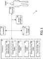
- FIG. 1 is a schematic illustration of a system 10, according to an embodiment of the invention, configured to determine timing of sensory stimulation provided to a subject 12 to increase sleep slow waves during a sleep session. Increasing sleep slow waves during a sleep session may cause subject 12 to feel more rested after the sleep session.
- System 10 is configured to determine a timing for the sensory stimulation provided to subject 12 that approximates the duration of naturally occurring sleep slow waves in subject 12. The duration of sleep slow waves varies from person to person. The duration of sleep slow waves in a single person may change over time (e.g., with age).
- System 10 is configured to customize the timing of the sensory stimulation for individual users (e.g., subject 12) to increase sleep slow waves in a given user.
- System 10 is configured to deliver probing (first) sensory stimulation to subject 12 and then determine a slow wave stimulation timing for subject 12 based on electrical brain activity of subject 12 caused by the probing stimulation.
- System 10 is configured to deliver slow wave (second) stimulation to subject 12 at the timing determined for subject 12 for the remainder of the sleep session.
- System 10 may be configured to cease providing the slow wave stimulation one or more times during the remainder of the sleep session if a likelihood of arousal is detected by system 10.
- Sleep slow waves are associated with slow wave activity (SWA) in subject 12 during the sleep session.
- SWA corresponds to the power of an electroencephalogram (EEG) signal in the 0.5-4.5 Hz band. In some embodiments, this band is set to 0.5-4 Hz.
- EEG electroencephalogram
- SWA has a typical behavior throughout cyclic variations of a given sleep session. SWA increases during non-rapid eye movement sleep (NREM), declines before the onset of rapid-eye-movement (REM) sleep, and remains low during REM. SWA in successive NREM episodes progressively decreases from one episode to the next. SWA may be estimated from an EEG for subject 12 during a given sleep session.
- the sensory stimuli may include different types of sensory stimuli.
- the different types may include odors, sounds, visual stimulation (e.g., lights flashed on open and/or closed eyes), touches, tastes, and/or other types of sensory stimuli.
- system 10 may be configured to deliver acoustic tones to subject 12.
- system 10 may be configured to determine an inter tone interval between acoustic tones delivered to subject 12 to increase sleep slow waves.
- System 10 comprises a sensory stimulator 16, a sensor 18, a processor 20, electronic storage 22, a user interface 24, and optionally other components.
- sensory stimulator 16 sensor 18, processor 20, electronic storage 22, and user interface 24 are shown as separate entities. This is not intended to be limiting. Some and/or all of the components of system 10 and/or other components may be grouped into one or more singular devices.
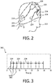
- FIG. 2 illustrates a headband 200 worn by a subject 202.
- Headband 200 includes sensing electrodes 204, a reference electrode 205, one or more devices associated with an EEG 206, a wireless audio device 208, and one or more audio speakers 210. Audio speakers 210 may be located in and/or near the ears of subject 202.
- the reference electrode 205 may be located behind the ear of subject 202.
- sensing electrodes 204 may be configured to generate output signals conveying information related to the frontal EEG of subject 202, left/right ocular information for subject 202, and/or other information.
- the output signals may be transmitted to a computing device (e.g., a bedside laptop) wirelessly and/or via wires.
- a computing device e.g., a bedside laptop
- Acoustic stimulation may be delivered to subject 202 via wireless audio device 208 and/or speakers 210.
- An audio signal including information related to auditory stimulation may be generated by the computing device and received by wireless audio device 208.
- Sensing electrodes 204, reference electrode 205, and devices 206 may be represented, for example, by sensor 18 in FIG. 1 .
- Wireless audio device 208 and speakers 210 may be represented, for example, by sensory stimulator 16 shown in FIG. 1 .
- sensory stimulator 16 is configured to provide sensory stimuli to subject 12.
- Sensory stimulator 16 is configured to provide sensory stimulation to subject 12 prior to a sleep session, during a sleep session, and optionally at other times.
- Sensory stimulator 16 is configured to provide sensory stimuli to subject 12 during slow wave sleep in a sleep session.
- Sensory stimulator 16 is configured to provide sensory stimulation to subject 12 to induce and/or adjust SWA in subject 12.
- Sensory stimulator 16 is configured such that inducing and/or adjusting SWA includes inducing, increasing, and enhancing sleep slow waves in subject 12.
- sensory stimulator 16 may be configured to induce, increase, and/or enhance sleep slow waves through non-invasive brain stimulation and/or other methods.
- Sensory stimulator 16 may be configured to induce, increase, and/or enhance sleep slow waves through non-invasive brain stimulation using sensory stimuli.
- the sensory stimuli include odors, sounds, visual stimulation, touches, tastes, and/or other stimuli.
- acoustic tones may be provided to subject 12 to induce, increase, and/or enhance sleep slow waves.
- Examples of sensory stimulator 16 may include one or more of a music player, a tone generator, a collection of electrodes on the scalp of subject 12, a unit to deliver vibratory stimulation (also known as somato-sensory stimulation), a coil generating a magnetic field to directly stimulate the brain's cortex, light generators, a fragrance dispenser, and/or other devices.
- Sensor 18 is configured to generate output signals conveying information related to a current sleep stage of subject 12.
- the current sleep stage of subject 12 may correspond to one or more of non-rapid eye movement (NREM) stage N1, stage N2, or stage N3 sleep, rapid eye movement (REM) sleep, and optionally other sleep stages.
- NREM stage 3 or stage 2 sleep may be slow wave sleep.
- Sensor 18 may comprise one or more sensors that measure such parameters directly.
- sensor 18 may include electrodes configured to detect electrical activity along the scalp of subject 12 resulting from current flows within the brain of subject 12.
- Sensor 18 may comprise one or more sensors that generate output signals conveying information related to a current sleep stage of the subject indirectly.
- one or more sensors 18 may generate an output based on a heart rate of subject 12 (e.g., sensor 18 may be a heart rate sensor located on the chest of subject 12, and/or be configured as a bracelet on a wrist of subject 12, and/or be located on another limb of subject 12), movement of subject 12 (e.g., sensor 18 may include a bracelet around the wrist and/or ankle of subject 12 with an accelerometer such that sleep may be analyzed using actigraphy signals), respiration of subject 12, and/or other characteristics of subject 12.
- sensor 18 is illustrated at a single location near subject 12, this is not intended to be limiting.
- Sensor 18 may include sensors disposed in a plurality of locations, such as for example, within (or in communication with) sensory stimulator 16, coupled (in a removable manner) with clothing of subject 12, worn by subject 12 (e.g., as a headband, wristband, etc.), positioned to point at subject 12 while subject 12 sleeps (e.g., a camera that conveys output signals related to movement of subject 12), and/or in other locations.
- sensors disposed in a plurality of locations, such as for example, within (or in communication with) sensory stimulator 16, coupled (in a removable manner) with clothing of subject 12, worn by subject 12 (e.g., as a headband, wristband, etc.), positioned to point at subject 12 while subject 12 sleeps (e.g., a camera that conveys output signals related to movement of subject 12), and/or in other locations.
- Processor 20 is configured to provide information processing capabilities in system 10.
- processor 20 may comprise one or more of a digital processor, an analog processor, and a digital circuit designed to process information, an analog circuit designed to process information, a state machine, and/or other mechanisms for electronically processing information.
- processor 20 is shown in FIG. 1 as a single entity, this is for illustrative purposes only.
- processor 20 may comprise a plurality of processing units. These processing units may be physically located within the same device (e.g., sensory stimulator 16), or processor 20 may represent processing functionality of a plurality of devices operating in coordination.
- processor 20 is configured to execute computer program modules.
- the computer program modules comprise a slow wave sleep detection module 30, a probing stimulation module 32, an identification module 34, a combination module 36, a stimulation timing module 38, a control module 40, and optionally other modules.
- Processor 20 may be configured to execute modules 30, 32, 34, 36, 38, and/or 40 by software; hardware; firmware; some combination of software, hardware, and/or firmware; and/or other mechanisms for configuring processing capabilities on processor 20.
- modules 30, 32, 34, 36, 38, and 40 are illustrated in FIG. 1 as being co-located within a single processing unit, in embodiments in which processor 20 comprises multiple processing units, one or more of modules 30, 32, 34, 36, 38, and/or 40 may be located remotely from the other modules.
- Slow wave sleep detection module 30 is configured to detect slow wave sleep in subject 12.
- Slow wave sleep detection module 30 is configured to detect slow wave sleep based on the output signals from sensor 18.
- slow wave sleep detection module 30 may identify slow wave sleep in subject 12 based on an analysis of the information conveyed by the output signals.
- the analysis may include generating and/or monitoring an EEG during a sleep session of subject 12.
- the EEG may be displayed, for example, by user interface 24.
- the analysis may include detecting slow wave sleep based on a ratio that characterizes the depth of sleep.
- slow wave sleep detection module 30 is configured to identify slow wave sleep in subject 12 responsive to an instantaneous slow wave sleep ratio p(t), estimated based on instantaneous powers ⁇ (t) and ⁇ (t), staying below a threshold ratio for longer than a given period of time.
- the threshold ratio and/or the given period of time may be determined based on previous sleep sessions of subject 12, and/or other information.
- the threshold ratio and/or the given period of time may be programmed at manufacture.
- the threshold ratio and/or the given period of time may be programmed at manufacture based on empirically accepted values such as a threshold ratio of about -2, and/or a given period of time of about 2 minutes.
- slow wave sleep may be detected based on the power level in the alpha band (8-12Hz) and/or the sigma band (11-15Hz) in addition to and/or instead of the beta band and the delta band.
- slow wave sleep detection module 30 may be configured to identify sleep stages in addition to slow wave sleep.
- slow wave sleep module 32 may be configured to identify a specific sleep stage (e.g., N1, N2, N3, REM, wakefulness) while subject 12 is sleeping.
- Probing stimulation module 32 is configured to control sensory stimulator 16 to provide probing sensory stimulation to subject 12 to induce sleep slow waves. Probing stimulation module 32 is configured to control sensory stimulator 16 to provide the probing stimulation responsive to detection of slow wave sleep by slow wave sleep detection module 30. In some embodiments, probing stimulation module 32 is configured such that the probing stimulation comprises three or more individual stimuli delivered to subject 12 with random intervals of time between the individual stimuli. In some embodiments, the probing stimulation comprises four or more individual stimuli. In some embodiments, the probing stimulation comprises five or more individual stimuli. In some embodiments, the random intervals of time between the individual stimuli are at least about two seconds. In some embodiments, the random intervals of time between the individual stimuli are at least about three seconds. In some embodiments, the random intervals of time between the individual stimuli are at least about four seconds.
- an individual slow wave lasts for about one second.
- a minimum random interval of at least two seconds may ensure that the induced sleep slow waves do not overlap (e.g., the end of a first slow wave does not overlap with the beginning of a second slow wave).
- probing stimulation module 32 may determine other probing stimulation parameters in addition to and/or instead of a quantity of, and a delivery interval for, individual stimuli. For example, for acoustic stimulation, probing stimulation module 32 may determine a tone volume, a tone pitch, and/or other parameters.
- the probing stimulation may be composed of a sequence of twenty 50-millisecond long acoustic tones having a frequency (pitch) between 500Hz and 2000Hz.
- the volume level of the acoustic tones may be 40dB.
- the random inter tone interval between tones may be between three and five seconds.
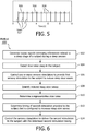
- FIG. 3 illustrates a series of acoustic tones 300 delivered as probing stimulation 302.
- the tones 300 have a random inter tone interval 304 of greater than or equal to about two seconds.
- FIG. 3 illustrates a series of 10 acoustic tones 300. This is not intended to be limiting.
- the number of tones and/or other individual stimuli used for probing stimulation may be set at manufacture, set and/or adjusted by a user via user interface 24, determined based on previous sleep sessions of subject 12, and/or determined by other methods.
- a user may include a doctor, a caregiver, subject 12, and/or other users.
- Changing the number of tones used during the probing stimulation may increase and/or decrease a signal to noise ratio in the EEG. It is known that the increase in signal-to-noise ratio is directly proportional to the square root of the number of tones used during the probing stimulation.
- combination module 36 is configured to perform time locked averaging and/or other operations on the EEG signal (e.g., the EEG generated by slow wave sleep detection module 30).
- Individual induced slow waves are aligned in time (with respect to the timing of the individual probing stimuli) and combined (e.g., averaged) to obtain a representative evoked sleep slow wave (e.g., this may be a typical slow wave which has a higher signal-to-noise ratio because of the averaging) which is used to obtain a higher-confidence estimate of the slow wave duration.
- This typical/representative slow wave has a higher signal-to-noise ratio that is proportional to the square root of the number of tones (for example) in the probing stimulation.
- the alignment of the slow waves is done according to the timing of the individual stimuli (e.g., tones) in the probing stimulation. The process is illustrated in FIG. 3A .
- the time locked average refers to a typical and representative slow wave 350.
- Individual portions (e.g., slow waves) 352, 354, 356, and 358 of the EEG 360 are aligned 362 based on the timing of tones 364 played during probing stimulation.
- identification module 34 may be configured to identify individual ones of the induced sleep slow waves (though this is not strictly required). Identification module 34 may be configured to identify the induced sleep slow waves based on the output signals from sensor 18 and/or other information. In some embodiments, identification module 34 may identify individual ones of the induced sleep slow waves based on information related to an EEG (e.g., generated by slow wave sleep detection module 30). Identification module 34 may determine one or more slow wave parameters related to the output signals from sensor 18 (e.g., one or more signals related to the EEG), and/or related to other signals. The one or more slow wave parameters may be related to one or more of a frequency, an amplitude, a shape, a timing, a duration, a phase, and/or other parameters of the output signals from sensors 18, and/or other signals.
- Identification module 34 may compare the determined slow wave parameters to one or more predetermined parameter thresholds. Identification module 34 may identify an individual induced sleep slow wave responsive to one or more of the slow wave parameters breaching one or more of the predetermined parameter thresholds.
- the predetermined parameter thresholds may be determined at manufacture, set and/or adjusted by a user via user interface 24, determined based on previous sleep sessions of subject, and/or determined by other methods. Identification module 34 may be configured to determine the slow wave parameters and/or compare the determined slow wave parameters to the one or more predetermined parameter thresholds one or more times during a sleep session.
- identification module 34 may be configured to determine the slow wave parameters and/or compare the determined slow wave parameters to the one or more predetermined parameter thresholds one or more times during a given period of time after the delivery of an individual stimulus during the probing stimulation. In some embodiments, identification module 34 may be configured to determine the slow wave parameters and/or compare the determined slow wave parameters to the one or more predetermined parameter thresholds continuously during the probing stimulation.
- identification module 34 may determine one or more of a shape, an amplitude, a timing, a phase, and/or a duration of an output signal from a sensor 18 associated with an EEG.
- identification module 34 may determine an amplitude of a first electrical activity peak, an amplitude of a second electrical activity peak, a timing of the first peak (e.g., relative to a probing stimulation acoustic tone), a timing of the second peak (e.g., relative to the same acoustic tone), a duration of time between the first peak and the second peak, and/or other slow wave parameters of the EEG signal.
- Identification module 34 may determine one or more slow wave parameters of the EEG signal during a two second period after the delivery of an acoustic tone that is part of the probing stimulation. Identification module 34 may compare a determined shape, amplitude, timing, and /or duration to predetermined shape, amplitude, timing, and/or duration thresholds. Responsive to a shape, amplitude, timing, phase, and/or a duration of the EEG signal breaching a threshold level, identification module 34 may identify an individual sleep slow wave.
- the acoustic tone may be one tone in series of tones delivered as probing stimulation by system 10. Identification module 34 may repeat the parameter determination and comparison process during the two seconds that follow additional individual probing stimulation tones.
- Combination module 36 is configured to determine a representative slow wave.
- the representative slow wave is determined based on a combination (e.g., a time locked average) of the identified induced sleep slow waves. Determining the representative slow may include determining one or more representative wave parameters.
- a given representative wave parameter may correspond to a given slow wave parameter.
- the given representative wave parameter may be and/or include a combination of the corresponding slow wave parameters determined one or more times for the individual sleep slow waves.
- combination module 36 may be configured such that the representative wave parameters include a first electrical activity peak representative amplitude, a second electrical activity peak representative amplitude, a representative timing of the first electrical activity peak, a representative timing of the second electrical activity peak, a representative duration of time between the first electrical activity peak and the second electrical activity peak, and/or other representative parameters.
- the first electrical activity peak representative amplitude may be determined based on an average and/or other combination of first electrical activity peak amplitudes determined by identification module 34 for the individually identified sleep slow waves.
- the second electrical activity peak representative amplitude, the representative timing of the first electrical activity peak, the representative timing of the second electrical activity peak, the representative duration of time between the first electrical activity peak and the second electrical activity peak, and/or other representative parameters may be determined by combination module 36 in a similar manner.
- Combination module 36 is configured such that determining a representative slow wave includes a timing based alignment of the individually identified sleep slow waves.
- the alignment may be based on the timing of the first electrical activity peak relative to the timing of an individual probing stimulus, the timing of the second electrical activity peak relative to the timing of the same individual probing stimulus, and/or other signal wave parameters.
- the timing of an individual tone that is part of the probing stimulus may be arbitrarily set to "0" seconds on a plot of electrical activity (e.g., in the brain of subject 12) versus time.
- Plotted lines representing the individually identified sleep slow waves may be overlapped on the electrical activity versus time plot. Representative parameters may be determined based on the overlapped sleep slow waves.
- Parameters that may be extracted include: the time and amplitude of the first positive peak (see 406 in FIG. 4 described below), the time and amplitude of the negative peak (see 420 in FIG. 4 described below), the time and amplitude of the second positive peak (see 408 in FIG. 4 described below), and/or other parameters.
- FIG. 4 illustrates a representative slow wave 400.
- Representative slow wave 400 is illustrated on a plot 402 of electrical activity versus time.
- Representative slow wave 400 may correspond to time locked average slow wave 350 shown in FIG. 3A , for example.
- Representative slow wave 400 is shown relative to the timing 404 of an acoustic tone, for example, provided during probing stimulation.
- Timing 404 is set to "0" seconds on plot 402.
- Representative slow wave 400 includes a first electrical activity peak amplitude 406, a negative electrical activity peak 420, a second electrical activity peak amplitude 408, a timing 410 of the first electrical activity peak, a timing 412 of the second electrical activity peak, and a duration of time 414 between first electrical activity peak 406 and second electrical activity peak 408.
- parameters 406, 408, 410, 412, 414, and/or other parameters may be determined based on a combination of corresponding slow wave parameters determined by identification module 34 (shown in FIG. 1 ), determined based on a timing based alignment of the individually identified sleep slow waves, and/or determined by other methods.
- stimulation timing module 38 is configured to determine timing of slow wave stimulation provided to subject 12.
- the slow wave stimulation is configured to increase sleep slow waves in subject 12 during the sleep session (e.g., after the probing stimulation has ceased). The timing determination is based on the representative slow wave.
- stimulation timing module 38 is configured to determine the timing of the slow wave stimulation based on an amount of time between the first electrical activity peak and the second electrical activity peak (e.g., duration of time 414 shown in FIG. 4 ) in the representative slow wave (e.g., representative slow wave 400 shown in FIG. 4 ).
- stimulation timing module 38 is configured such that the timing of the slow wave stimulation comprises a regular, repeating interval of time between individual stimuli delivered to subject 12.
- stimulation timing module 38 is configured such that the regular, repeating interval of time between individual stimuli (e.g., tones) of the slow wave stimulation is the amount of time between the first electrical activity peak and the second electrical activity peak in the representative slow wave.
- an inter tone interval may be determined by stimulation timing module 38 to be the amount of time between the first electrical activity peak and the second electrical activity peak in the representative slow wave.
- FIG. 5 illustrates a fixed inter tone interval 500 for a series of 12 tones 502 delivered as slow wave stimulation. Fixed inter tone interval 500 in FIG. 5 may correspond to, for example, duration of time 414 shown in FIG. 4 .
- stimulation timing module 38 is configured such that the timing of the slow wave stimulation is variable between individual stimuli.
- stimulation timing module 38 may be configured such that the timing of the slow wave stimulation is determined based the amount of time between the first electrical activity peak and the second electrical activity peak.
- the timing of the slow wave stimulation may correspond to a given phase of a sleep slow wave.
- the given phase may be associated with a slow wave's down state (e.g., negative peak 420 of the slow wave shown in FIG. 4 ) and/or a slow wave's up state (e.g., generally the second positive peak 408 in FIG. 4 ).
- Stimulation timing module 38 may be configured to determine whether the timing of the slow wave stimulation is the amount of time between the first electrical activity peak and the second electrical activity peak and/or is only based on the amount of time between the peaks via information entered and/or selected by a user via user interface 24, instructions programmed during manufacture of system 10, and/or by other methods.
- Control module 40 is configured to control sensory stimulator 16 to deliver the slow wave stimulation to subject 12 with the timing determined by stimulation timing module 38.
- Control module 40 is configured to control sensory stimulator 16 to deliver the slow wave stimulation to subject 12 with the timing determined by stimulation timing module 38 while subject 12 is determined to be in slow wave sleep (e.g., stage N3).
- control module 40 may control sensory stimulator 16 to provide the slow wave stimulation during the sleep session such that the slow wave stimulation does not wake subject 12.
- control module 40 may control sensory stimulator 16 to provide the slow wave stimulation at a low intensity level.
- control module 40 may cause sensory stimulator 16 to deliver acoustic stimulation to subject 12 to increase sleep slow waves with an inter tone interval determined by stimulation timing module 38 while subject 12 is determined to be in stage N3 sleep.
- Control module 40 may control sensory stimulator 16 to deliver slow wave stimulation to subject 12 during stage N3 sleep because the likelihood for slow-wave induction, and/or increase during the specific sleep stage may be comparatively higher than in other sleep stages, the user may be less likely to be awakened by the slow wave stimuli, and/or for other reasons.
- control module 40 is configured to control sensory stimulator 16 to cease providing the slow wave stimulation to subject 12 responsive to slow wave sleep detection module 30 indicating that subject 12 is waking up.
- system 10 is configured such that the operations performed by slow wave sleep detection module 30, probing stimulation module 32, identification module 34, combination module 36, stimulation timing module 38, and/or other modules are performed only once after a first period of slow wave sleep within a sleep session.
- control module 40 may control sensory stimulators 16 to deliver the slow wave stimulation at the timing determined by stimulation timing module 38 during individual periods of slow wave sleep for the rest of the sleep session.
- control module 40 may control sensory stimulators 16 to deliver the slow wave stimulation at the same timing during periods of slow wave sleep in future sleep sessions of subject 12.
- the timing determined by stimulation module 38 may be stored in electronic storage 38 and retrieved by control module 40 during future sleep sessions, for example.
- control module 40 may cause information related to the sleep session of subject 12 to be stored in electronic storage 22.
- system 10 is configured such that the operations performed by slow wave sleep detection module 30, probing stimulation module 32, identification module 34, combination module 36, stimulation timing module 38, and/or other modules are performed for two or more individual periods of slow wave sleep within a sleep session.
- control module 40 may control sensory stimulators 16 to deliver the slow wave stimulation at the most recent timing determined by stimulation timing module 38.
- Control module 40 may control sensory stimulator 16 to deliver the slow wave stimulation at the most recently determined timing for the corresponding individual period of slow wave sleep until a new timing is determined by stimulation timing module 38, and/or for other periods of time.
- system 10 is configured such that the operations performed by slow wave sleep detection module 30, probing stimulation module 32, identification module 34, combination module 36, stimulation timing module 38, and/or other modules are performed every time a slow wave sleep cycle is detected during a sleep session.
- the time required to deliver the probing stimulation and obtain a customized timing for the slow wave stimulation may be shorter than one minute.
- Control module 40 may control sensory stimulator 16 to deliver the slow wave stimulation at the most recently determined timing for the corresponding individual period of slow wave sleep until a new timing is determined by stimulation timing module 38 for the next period of slow wave sleep.
- the probing stimulation may be applied during the first use of system 10 by subject 12.
- the resulting timing of the slow wave stimulation determined by stimulation timing module 38 may be used by control module 40 for the periods of slow wave sleep during the rest of the sleep session and future sleep sessions of subject 12.
- the probing stimulation (e.g., lasting for less than a minute) may be applied at the beginning of individual periods of slow wave sleep and the resulting customized inter tone interval (for example) may be used only for the remaining portion of that period of slow wave sleep within the sleep session.
- the embodiment described in this example may be used when the duration of sleep slow waves (e.g., about one second) varies for individual periods of slow wave sleep in subject 12, for example, when slow wave variations related to age are expected, and/or for other applications.
- the frequency with which the operations of slow wave sleep detection module 30, probing stimulation module 32, identification module 34, combination module 36, stimulation timing module 38, and/or other modules are performed may be determined at manufacture, determined based on user input via user interface 24, determined based on previous sleep sessions of subject 12, and/or determined by other methods.
- the various example frequencies described herein e.g., once at the first use of system 10, once per period of slow wave sleep, etc. are not intended to be limiting.
- the frequency with which the operations described above are performed may be any frequency that allows system 10 to function as described.
- Electronic storage 22 comprises electronic storage media that electronically stores information.
- the electronic storage media of electronic storage 22 may comprise one or both of system storage that is provided integrally (i.e., substantially non-removable) with system 10 and/or removable storage that is removably connectable to system 10 via, for example, a port (e.g., a USB port, a firewire port, etc.) or a drive (e.g., a disk drive, etc.).
- a port e.g., a USB port, a firewire port, etc.
- a drive e.g., a disk drive, etc.
- Electronic storage 22 may comprise one or more of optically readable storage media (e.g., optical disks, etc.), magnetically readable storage media (e.g., magnetic tape, magnetic hard drive, floppy drive, etc.), electrical charge-based storage media (e.g., EPROM, RAM, etc.), solid-state storage media (e.g., flash drive, etc.), and/or other electronically readable storage media.
- Electronic storage 22 may store software algorithms, information determined by processor 20, information received from subject 12, and/or other information that enables system 10 to function properly.
- Electronic storage 22 may be (in whole or in part) a separate component within system 10, or electronic storage 22 may be provided (in whole or in part) integrally with one or more other components of system 10 (e.g., processor 20).
- User interface 24 is configured to provide an interface between system 10 and subject 12, and/or other users through which subject 12 and/or other users may provide information to and receive information from system 10. This enables data, cues, results, and/or instructions and any other communicable items, collectively referred to as "information," to be communicated between a user (e.g., subject 12) and one or more of sensory stimulator 16, sensor 18, processor 20, and/or other components of system 10. For example, an EEG may be displayed to a caregiver via user interface 24.
- Examples of interface devices suitable for inclusion in user interface 24 comprise a keypad, buttons, switches, a keyboard, knobs, levers, a display screen, a touch screen, speakers, a microphone, an indicator light, an audible alarm, a printer, a tactile feedback device, and/or other interface devices.
- user interface 24 comprises a plurality of separate interfaces.
- user interface 24 comprises at least one interface that is provided integrally with sensory stimulator 16 and/or other components of system 10.
- user interface 24 may be integrated with a removable storage interface provided by electronic storage 22.
- information may be loaded into system 10 from removable storage (e.g., a smart card, a flash drive, a removable disk, etc.) that enables the user(s) to customize the implementation of system 10.
- removable storage e.g., a smart card, a flash drive, a removable disk, etc.
- Other exemplary input devices and techniques adapted for use with system 10 as user interface 24 comprise, but are not limited to, an RS-232 port, RF link, an IR link, modem (telephone, cable or other).
- any technique for communicating information with system 10 is contemplated by the present disclosure as user interface 24.
- FIG. 6 illustrates a method 600, not forming part of the invention, for determining timing of sensory stimulation provided to a subject to increase sleep slow waves during a sleep session with a timing determination system.
- slow wave sleep may be and/or include stage N3 sleep (e.g., according to the new denomination), S4 sleep (e.g., according to the former denomination), deep sleep and/or other slow wave sleep.
- stage N3 sleep, S4 sleep, and/or deep sleep may all refer to the same type of sleep.
- the system comprises one or more sensory stimulators, one or more sensors, one or more processors, and/or other components.
- the one or more processors are configured to execute computer program modules.
- the computer program modules comprise a slow wave sleep detection module, a probing stimulation module, an identification module, a combination module, a stimulation timing module, and/or other modules.
- the operations of method 600 presented below are intended to be illustrative. In some embodiments, method 600 may be accomplished with one or more additional operations not described, and/or without one or more of the operations discussed. Additionally, the order in which the operations of method 600 are illustrated in FIG. 6 and described below is not intended to be limiting.
- method 600 may be implemented in one or more processing devices (e.g., a digital processor, an analog processor, a digital circuit designed to process information, an analog circuit designed to process information, a state machine, and/or other mechanisms for electronically processing information).
- the one or more processing devices may include one or more devices executing some or all of the operations of method 600 in response to instructions stored electronically on an electronic storage medium.
- the one or more processing devices may include one or more devices configured through hardware, firmware, and/or software to be specifically designed for execution of one or more of the operations of method 600.
- operation 602 output signals conveying information related to a sleep stage of the subject during a sleep session are generated.
- operation 602 is performed by one or more sensors the same as or similar to sensors 18 (shown in FIG. 1 and described herein).
- slow wave sleep is detected in the subject.
- Slow wave sleep is detected based on the output signals.
- operation 604 is performed by a computer program module the same as or similar to slow wave sleep detection module 30 (shown in FIG. 1 and described herein).
- the one or more sensory stimulators are controlled to provide first sensory stimulation to the subject to induce sleep slow waves.
- the first sensory stimulation may be probing sensory stimulation and/or other stimulation.
- the first sensory stimulation may comprise three or more individual stimuli delivered to the subject with random intervals of time between the individual stimuli.
- the random intervals of time between the individual stimuli may be at least two seconds.
- the random intervals of time may be at least 3 seconds.
- the random intervals of time may be at least 4 seconds.
- operation 606 is performed by a computer program module the same as or similar to probing stimulation module 32 (shown in FIG. 1 and described herein).
- the following operations 608 and 610 may be combined into a single operation.
- the single operation may be and/or include performing a time locked average and/or other operations on the EEG signal.
- Individual induced slow waves may be aligned in time (with respect to the timing of the individual probing stimuli) and combined (e.g., averaged) to obtain a representative evoked sleep slow wave (e.g., this may be a typical slow wave which has a higher signal-to-noise ratio because of the averaging) which is used to obtain a higher-confidence estimate of the slow wave duration.
- the alignment of the slow waves is done according to the timing of the individual stimuli (e.g., tones) in the probing stimulation. The process is illustrated in FIG. 3A as described above.
- induced sleep slow waves may be identified (though this may not be required as a separate step for time locked averaging).
- the induced sleep slow waves may be identified based on the output signals.
- operation 608 is performed by a computer program module the same as or similar to identification module 34 (shown in FIG. 1 and described herein).
- a representative slow wave is determined.
- the representative slow wave is determined based on a combination of the identified induced sleep slow waves (e.g., time locked averaging).
- the representative slow wave may include a first electrical activity peak and a second electrical activity peak.
- operation 610 is performed by a computer program module the same as or similar to combination module 36 (shown in FIG. 1 and described herein).
- timing of second stimulation provided to the subject is determined.
- the second stimulation is configured to increase sleep slow waves.
- the timing of the second stimulation is determined based on the representative slow wave.
- the timing of the second stimulation may be determined based on an amount of time between the first electrical activity peak and the second electrical activity peak of the representative slow wave.
- the timing of the second stimulation comprises a regular, repeating interval of time between individual stimuli delivered to the subject.
- operation 612 is performed by a computer program module the same as or similar to stimulation timing module 38 (shown in FIG. 1 and described herein).
- operation 614 the sensory stimulators are controlled to deliver the second stimulation to the subject with the determined second stimulation timing.
- operation 614 is performed by a computer program module the same as or similar to control module 40 (shown in FIG. 1 and described herein).
- any reference signs placed between parentheses shall not be construed as limiting the claim.
- the word “comprising” or “including” does not exclude the presence of elements or steps other than those listed in a claim.
- several of these means may be embodied by one and the same item of hardware.
- the word “a” or “an” preceding an element does not exclude the presence of a plurality of such elements.
- any device claim enumerating several means several of these means may be embodied by one and the same item of hardware.
- the mere fact that certain elements are recited in mutually different dependent claims does not indicate that these elements cannot be used in combination.
Claims (5)
- System (10), das konfiguriert ist, zur Zeitbestimmung der sensorischen Stimulation die einem Subjekt (12) bereitgestellt wird, um die Langsamwellen im Schlaf während einer Schlafsitzung zu erhöhen, wobei das System umfasst:ein oder mehrere sensorische Stimulatoren (16), die konfiguriert sind, um dem Subjekt während der Schlafsitzung sensorische Stimuli bereitzustellen;einen oder mehrere Sensoren (18), die konfiguriert sind, um Ausgangssignale zu erzeugen, die Informationen über eine Schlafphase des Subjekts während der Schlafsitzung übermitteln; undeinen oder mehrere Prozessoren (20), die konfiguriert sind, um Computerprogrammmodule auszuführen, wobei die Computerprogrammmodule umfassen:ein Langsamwellenschlaf-Erfassungsmodul (30), das konfiguriert ist, um Langsamwellenschlaf im Subjekt basierend auf den Ausgangssignalen zu erfassen;ein Sondierungsstimulationsmodul (32), das so konfiguriert ist, dass es als Reaktion auf die Erfassung eines Langsamwellenschlafes, den einen oder die mehreren sensorischen Stimulatoren steuert, um dem Subjekt eine erste sensorische Stimulation bereitzustellen, um Langsamwellen im Schlaf zu induzieren, wobei die erste sensorische Stimulation einzelne Sondierungsstimuli umfasst;ein Kombinationsmodul (36), das konfiguriert ist, um eine repräsentative langsame Welle basierend auf den induzierten Langsamwellen im Schlaf zu bestimmen, wobei die repräsentative Langsamwelle eine Kombination von einzelnen induzierten Langsamwellen umfasst, wobei die Bestimmung das zeitliche Ausrichten der einzelnen induzierten Langsamwellen in Bezug auf einen Zeitpunkt der einzelnen angewendeten Sondierungsstimuli umfasst, und anschließendes Kombinieren der ausgerichteten Wellen; undein Stimulationszeitmodul (38), das konfiguriert ist, um der Zeitpunkt einzelner Stimuli einer zweiten Stimulation zu bestimmen, die dem Subjekt durch den einen oder die mehreren sensorischen Stimulatoren bereitgestellt werden soll, wobei die zweite Stimulation konfiguriert ist, um die Langsamwellen im Schlaf im Subjekt während der Schlafsitzung zu erhöhen, wobei die Zeitbestimmung auf der repräsentativen Langsamwelle basiert ist.
- System nach Anspruch 1, ferner umfassend ein Steuermodul (40), das konfiguriert ist, um den einen oder die mehreren sensorischen Stimulatoren zu steuern, um die zweite Stimulation an das Subjekt mit dem durch das Stimulationszeitmodul bestimmten Zeitpunkt zu liefern.
- System nach Anspruch 1, wobei das Kombinationsmodul (36) so konfiguriert ist, dass die repräsentative langsame Welle einen ersten elektrischen Aktivitätspeak und einen zweiten elektrischen Aktivitätspeak enthält, und wobei das Stimulationszeitmodul konfiguriert ist zur Zeitbestimmung der zweiten Stimulation basierend auf einer Zeitspanne zwischen dem ersten elektrischen Aktivitätspeak und dem zweiten elektrischen Aktivitätspeak.
- System nach Anspruch 1, wobei das Sondierungsstimulationsmodul (32) so konfiguriert ist, dass die erste sensorische Stimulation drei oder mehr einzelne Sondierungsstimuli umfasst, die mit zufälligen Zeitintervallen zwischen den einzelnen Sondierungsstimuli an das Subjekt abgegeben werden, und wobei die zufällige Zeitintervalle zwischen den einzelnen Sondierungsstimuli mindestens zwei Sekunden betragen.
- System nach Anspruch 1, wobei das Stimulationszeitmodul (38) so konfiguriert ist, dass der Zeitpunkt der zweiten Stimulation ein regelmäßiges, sich wiederholendes Zeitintervall zwischen einzelnen Stimuli umfasst, die an das Subjekt abgegeben werden.
Applications Claiming Priority (2)
| Application Number | Priority Date | Filing Date | Title |
|---|---|---|---|
| US201361886277P | 2013-10-03 | 2013-10-03 | |
| PCT/IB2014/064650 WO2015049613A1 (en) | 2013-10-03 | 2014-09-19 | System and method for determining timing of sensory stimulation during sleep |
Publications (2)
| Publication Number | Publication Date |
|---|---|
| EP3052174A1 EP3052174A1 (de) | 2016-08-10 |
| EP3052174B1 true EP3052174B1 (de) | 2020-08-26 |
Family
ID=51845456
Family Applications (1)
| Application Number | Title | Priority Date | Filing Date |
|---|---|---|---|
| EP14792875.8A Active EP3052174B1 (de) | 2013-10-03 | 2014-09-19 | System zur zeitbestimmung einer sensorischer stimulation während des schlafes |
Country Status (5)
| Country | Link |
|---|---|
| US (1) | US10080860B2 (de) |
| EP (1) | EP3052174B1 (de) |
| JP (1) | JP6470743B2 (de) |
| CN (1) | CN105592881B (de) |
| WO (1) | WO2015049613A1 (de) |
Families Citing this family (22)
| Publication number | Priority date | Publication date | Assignee | Title |
|---|---|---|---|---|
| EP4133997A1 (de) | 2013-07-08 | 2023-02-15 | ResMed Sensor Technologies Limited | Ein von einem prozessor und einem system ausgeführtes verfahren zur verwaltung des schlafes |
| US11648373B2 (en) | 2013-07-08 | 2023-05-16 | Resmed Sensor Technologies Limited | Methods and systems for sleep management |
| CN104814735A (zh) * | 2015-05-22 | 2015-08-05 | 京东方科技集团股份有限公司 | 判断大脑是否疲劳的方法和装置 |
| US10448883B2 (en) | 2015-07-21 | 2019-10-22 | Massachusetts Institute Of Technology | Methods and apparatus for neuromodulation |
| CN108430568B (zh) * | 2015-12-22 | 2022-09-27 | 皇家飞利浦有限公司 | 基于睡眠深度在睡眠期间调节感觉刺激的强度的系统和方法 |
| CN108697890B (zh) * | 2015-12-28 | 2022-05-27 | 康维格医疗控股有限公司 | 一种通过同步激活神经治疗各种神经疾病的系统和方法 |
| US11052220B2 (en) | 2016-06-27 | 2021-07-06 | Koninklijke Philips N.V. | System and method for adjusting the volume of auditory stimulation during sleep based on sleep depth latencies |
| KR102063926B1 (ko) | 2016-09-23 | 2020-01-08 | 기초과학연구원 | 뇌 자극 방법 |
| WO2018056733A1 (ko) | 2016-09-23 | 2018-03-29 | 기초과학연구원 | 뇌 자극 장치 및 이의 용도 |
| EP3551045A1 (de) * | 2016-12-08 | 2019-10-16 | Koninklijke Philips N.V. | Bestimmung einer korrigierten stimulationszeitplanung für eine person während des schlafes |
| EP3558099B1 (de) * | 2016-12-22 | 2021-06-30 | Koninklijke Philips N.V. | System zur ausgabe eines indikators, der für die wirkungen der an ein schlafendes subjekt abgegebenen stimulation repräsentativ ist |
| EP3562382B1 (de) * | 2016-12-28 | 2023-10-04 | Koninklijke Philips N.V. | System zum bestimmen, ob ein subjekt wahrscheinlich durch therapeutische stimulationen während schlafsitzungen gestört wird |
| CN107174239A (zh) * | 2017-07-05 | 2017-09-19 | 李震中 | 一种睡眠监测仪 |
| US11318278B2 (en) | 2017-09-13 | 2022-05-03 | Massachusetts Institute Of Technology | Methods and apparatus for inducing or modifying sleep |
| US11541201B2 (en) * | 2017-10-04 | 2023-01-03 | Neurogeneces, Inc. | Sleep performance system and method of use |
| US11116935B2 (en) * | 2018-05-10 | 2021-09-14 | Koninklijke Philips N.V. | System and method for enhancing sensory stimulation delivered to a user using neural networks |
| AU2018440943A1 (en) * | 2018-09-13 | 2021-05-20 | Elemind Technologies, Inc. | Methods and apparatus for inducing or modifying sleep |
| CA3112564A1 (en) * | 2018-09-14 | 2020-03-19 | Neuroenhancement Lab, LLC | System and method of improving sleep |
| WO2020064668A1 (en) * | 2018-09-28 | 2020-04-02 | Koninklijke Philips N.V. | System and method for delivering sensory stimulation during sleep based on demographic information |
| EP3669921A1 (de) | 2018-12-17 | 2020-06-24 | Koninklijke Philips N.V. | System und verfahren zur bereitstellung von auditiver schlafstimulation |
| CN109925587A (zh) * | 2019-03-18 | 2019-06-25 | 西安电子科技大学 | 一种基于生物低噪放的深度睡眠改善检测系统及方法 |
| WO2020193551A1 (en) * | 2019-03-28 | 2020-10-01 | Koninklijke Philips N.V. | Method and system to deliver timed and grouped sensory stimulation |
Citations (1)
| Publication number | Priority date | Publication date | Assignee | Title |
|---|---|---|---|---|
| WO2005055802A2 (en) * | 2003-11-21 | 2005-06-23 | First Principles, Inc. | Sleep guidance system and related methods |
Family Cites Families (9)
| Publication number | Priority date | Publication date | Assignee | Title |
|---|---|---|---|---|
| JP2725039B2 (ja) * | 1988-12-23 | 1998-03-09 | パイオニア株式会社 | 脳波誘導装置 |
| US20090062676A1 (en) * | 2003-05-06 | 2009-03-05 | George Mason Intellectual Property | Phase and state dependent eeg and brain imaging |
| US20070112277A1 (en) | 2005-10-14 | 2007-05-17 | Fischer Russell J | Apparatus and method for the measurement and monitoring of bioelectric signal patterns |
| WO2008039930A2 (en) * | 2006-09-28 | 2008-04-03 | Wisconsin Alumni Research Foundation | Method and apparatus for promoting restorative sleep |
| US8391966B2 (en) * | 2009-03-16 | 2013-03-05 | Neurosky, Inc. | Sensory-evoked potential (SEP) classification/detection in the time domain |
| US20100318007A1 (en) * | 2009-06-10 | 2010-12-16 | O'brien Donald J | Electromechanical tactile stimulation devices and methods |
| JP5544826B2 (ja) | 2009-10-30 | 2014-07-09 | トヨタ自動車株式会社 | 刺激効果予測装置、刺激効果予測方法及び車両制御装置 |
| US8382484B2 (en) | 2011-04-04 | 2013-02-26 | Sheepdog Sciences, Inc. | Apparatus, system, and method for modulating consolidation of memory during sleep |
| US8892205B2 (en) | 2011-12-07 | 2014-11-18 | Otologics, Llc | Sleep apnea control device |
-
2014
- 2014-09-19 CN CN201480054517.7A patent/CN105592881B/zh active Active
- 2014-09-19 JP JP2016519745A patent/JP6470743B2/ja active Active
- 2014-09-19 EP EP14792875.8A patent/EP3052174B1/de active Active
- 2014-09-19 WO PCT/IB2014/064650 patent/WO2015049613A1/en active Application Filing
- 2014-09-19 US US15/021,793 patent/US10080860B2/en active Active
Patent Citations (1)
| Publication number | Priority date | Publication date | Assignee | Title |
|---|---|---|---|---|
| WO2005055802A2 (en) * | 2003-11-21 | 2005-06-23 | First Principles, Inc. | Sleep guidance system and related methods |
Also Published As
| Publication number | Publication date |
|---|---|
| WO2015049613A1 (en) | 2015-04-09 |
| US10080860B2 (en) | 2018-09-25 |
| US20160220783A1 (en) | 2016-08-04 |
| CN105592881B (zh) | 2019-09-03 |
| JP2016538009A (ja) | 2016-12-08 |
| EP3052174A1 (de) | 2016-08-10 |
| CN105592881A (zh) | 2016-05-18 |
| JP6470743B2 (ja) | 2019-02-13 |
Similar Documents
| Publication | Publication Date | Title |
|---|---|---|
| EP3052174B1 (de) | System zur zeitbestimmung einer sensorischer stimulation während des schlafes | |
| US10220183B2 (en) | Adjustment of sensory stimulation intensity to enhance sleep slow wave activity | |
| US10512428B2 (en) | System and method for facilitating sleep stage transitions | |
| EP2983577B1 (de) | System zur verbesserung langsamer wellenaktivitäten im schlaf auf grundlage der herztätigkeit | |
| EP3102094B1 (de) | System und verfahren zur bestimmung der sensorischen stimulation einer person während einer schlafsitzung | |
| US10729875B2 (en) | System and method for adjusting duration of sensory stimulation during sleep to enhance slow wave activity | |
| US10137276B2 (en) | System and method for sleep session management based on slow wave sleep activity in a subject | |
| EP2950868B1 (de) | System für verbesserte wissenskonsolidierung durch langsamwelleninduktion im schlaf und sensorische kontextneuerstellung | |
| US20160310696A1 (en) | System and method for enhancing sleep slow wave activity based on cardiac characteristics or respiratory characterics | |
| EP3474936B1 (de) | System zur einstellung der intensität von sensorischer stimulation während des schlafes auf der grundlage von schlaftiefelatenzen | |
| US10537704B2 (en) | System and method for increasing the restorative value of a nap | |
| EP3723598B1 (de) | System und verfahren zur bestimmung der schlafbeginnlatenz | |
| EP3229662B1 (de) | System zur einstellung von kriterien zur detektion langsamer wellen |
Legal Events
| Date | Code | Title | Description |
|---|---|---|---|
| PUAI | Public reference made under article 153(3) epc to a published international application that has entered the european phase |
Free format text: ORIGINAL CODE: 0009012 |
|
| 17P | Request for examination filed |
Effective date: 20160503 |
|
| AK | Designated contracting states |
Kind code of ref document: A1 Designated state(s): AL AT BE BG CH CY CZ DE DK EE ES FI FR GB GR HR HU IE IS IT LI LT LU LV MC MK MT NL NO PL PT RO RS SE SI SK SM TR |
|
| AX | Request for extension of the european patent |
Extension state: BA ME |
|
| DAX | Request for extension of the european patent (deleted) | ||
| STAA | Information on the status of an ep patent application or granted ep patent |
Free format text: STATUS: EXAMINATION IS IN PROGRESS |
|
| 17Q | First examination report despatched |
Effective date: 20171204 |
|
| RAP1 | Party data changed (applicant data changed or rights of an application transferred) |
Owner name: KONINKLIJKE PHILIPS N.V. |
|
| GRAP | Despatch of communication of intention to grant a patent |
Free format text: ORIGINAL CODE: EPIDOSNIGR1 |
|
| STAA | Information on the status of an ep patent application or granted ep patent |
Free format text: STATUS: GRANT OF PATENT IS INTENDED |
|
| RIC1 | Information provided on ipc code assigned before grant |
Ipc: A61B 5/04 20060101ALN20200219BHEP Ipc: A61M 21/00 20060101ALN20200219BHEP Ipc: A61M 21/02 20060101AFI20200219BHEP Ipc: A61B 5/048 20060101ALI20200219BHEP Ipc: A61B 5/00 20060101ALI20200219BHEP |
|
| RIC1 | Information provided on ipc code assigned before grant |
Ipc: A61B 5/048 20060101ALI20200226BHEP Ipc: A61M 21/00 20060101ALN20200226BHEP Ipc: A61B 5/04 20060101ALN20200226BHEP Ipc: A61B 5/00 20060101ALI20200226BHEP Ipc: A61M 21/02 20060101AFI20200226BHEP |
|
| INTG | Intention to grant announced |
Effective date: 20200320 |
|
| GRAS | Grant fee paid |
Free format text: ORIGINAL CODE: EPIDOSNIGR3 |
|
| GRAA | (expected) grant |
Free format text: ORIGINAL CODE: 0009210 |
|
| STAA | Information on the status of an ep patent application or granted ep patent |
Free format text: STATUS: THE PATENT HAS BEEN GRANTED |
|
| AK | Designated contracting states |
Kind code of ref document: B1 Designated state(s): AL AT BE BG CH CY CZ DE DK EE ES FI FR GB GR HR HU IE IS IT LI LT LU LV MC MK MT NL NO PL PT RO RS SE SI SK SM TR |
|
| REG | Reference to a national code |
Ref country code: GB Ref legal event code: FG4D |
|
| REG | Reference to a national code |
Ref country code: CH Ref legal event code: EP |
|
| REG | Reference to a national code |
Ref country code: AT Ref legal event code: REF Ref document number: 1305765 Country of ref document: AT Kind code of ref document: T Effective date: 20200915 |
|
| REG | Reference to a national code |
Ref country code: IE Ref legal event code: FG4D |
|
| REG | Reference to a national code |
Ref country code: DE Ref legal event code: R096 Ref document number: 602014069446 Country of ref document: DE |
|
| REG | Reference to a national code |
Ref country code: LT Ref legal event code: MG4D |
|
| PG25 | Lapsed in a contracting state [announced via postgrant information from national office to epo] |
Ref country code: FI Free format text: LAPSE BECAUSE OF FAILURE TO SUBMIT A TRANSLATION OF THE DESCRIPTION OR TO PAY THE FEE WITHIN THE PRESCRIBED TIME-LIMIT Effective date: 20200826 Ref country code: HR Free format text: LAPSE BECAUSE OF FAILURE TO SUBMIT A TRANSLATION OF THE DESCRIPTION OR TO PAY THE FEE WITHIN THE PRESCRIBED TIME-LIMIT Effective date: 20200826 Ref country code: SE Free format text: LAPSE BECAUSE OF FAILURE TO SUBMIT A TRANSLATION OF THE DESCRIPTION OR TO PAY THE FEE WITHIN THE PRESCRIBED TIME-LIMIT Effective date: 20200826 Ref country code: GR Free format text: LAPSE BECAUSE OF FAILURE TO SUBMIT A TRANSLATION OF THE DESCRIPTION OR TO PAY THE FEE WITHIN THE PRESCRIBED TIME-LIMIT Effective date: 20201127 Ref country code: PT Free format text: LAPSE BECAUSE OF FAILURE TO SUBMIT A TRANSLATION OF THE DESCRIPTION OR TO PAY THE FEE WITHIN THE PRESCRIBED TIME-LIMIT Effective date: 20201228 Ref country code: NO Free format text: LAPSE BECAUSE OF FAILURE TO SUBMIT A TRANSLATION OF THE DESCRIPTION OR TO PAY THE FEE WITHIN THE PRESCRIBED TIME-LIMIT Effective date: 20201126 Ref country code: LT Free format text: LAPSE BECAUSE OF FAILURE TO SUBMIT A TRANSLATION OF THE DESCRIPTION OR TO PAY THE FEE WITHIN THE PRESCRIBED TIME-LIMIT Effective date: 20200826 Ref country code: BG Free format text: LAPSE BECAUSE OF FAILURE TO SUBMIT A TRANSLATION OF THE DESCRIPTION OR TO PAY THE FEE WITHIN THE PRESCRIBED TIME-LIMIT Effective date: 20201126 |
|
| REG | Reference to a national code |
Ref country code: NL Ref legal event code: MP Effective date: 20200826 |
|
| REG | Reference to a national code |
Ref country code: AT Ref legal event code: MK05 Ref document number: 1305765 Country of ref document: AT Kind code of ref document: T Effective date: 20200826 |
|
| PG25 | Lapsed in a contracting state [announced via postgrant information from national office to epo] |
Ref country code: PL Free format text: LAPSE BECAUSE OF FAILURE TO SUBMIT A TRANSLATION OF THE DESCRIPTION OR TO PAY THE FEE WITHIN THE PRESCRIBED TIME-LIMIT Effective date: 20200826 Ref country code: NL Free format text: LAPSE BECAUSE OF FAILURE TO SUBMIT A TRANSLATION OF THE DESCRIPTION OR TO PAY THE FEE WITHIN THE PRESCRIBED TIME-LIMIT Effective date: 20200826 Ref country code: LV Free format text: LAPSE BECAUSE OF FAILURE TO SUBMIT A TRANSLATION OF THE DESCRIPTION OR TO PAY THE FEE WITHIN THE PRESCRIBED TIME-LIMIT Effective date: 20200826 Ref country code: RS Free format text: LAPSE BECAUSE OF FAILURE TO SUBMIT A TRANSLATION OF THE DESCRIPTION OR TO PAY THE FEE WITHIN THE PRESCRIBED TIME-LIMIT Effective date: 20200826 Ref country code: IS Free format text: LAPSE BECAUSE OF FAILURE TO SUBMIT A TRANSLATION OF THE DESCRIPTION OR TO PAY THE FEE WITHIN THE PRESCRIBED TIME-LIMIT Effective date: 20201226 |
|
| PG25 | Lapsed in a contracting state [announced via postgrant information from national office to epo] |
Ref country code: SM Free format text: LAPSE BECAUSE OF FAILURE TO SUBMIT A TRANSLATION OF THE DESCRIPTION OR TO PAY THE FEE WITHIN THE PRESCRIBED TIME-LIMIT Effective date: 20200826 Ref country code: RO Free format text: LAPSE BECAUSE OF FAILURE TO SUBMIT A TRANSLATION OF THE DESCRIPTION OR TO PAY THE FEE WITHIN THE PRESCRIBED TIME-LIMIT Effective date: 20200826 Ref country code: EE Free format text: LAPSE BECAUSE OF FAILURE TO SUBMIT A TRANSLATION OF THE DESCRIPTION OR TO PAY THE FEE WITHIN THE PRESCRIBED TIME-LIMIT Effective date: 20200826 Ref country code: CZ Free format text: LAPSE BECAUSE OF FAILURE TO SUBMIT A TRANSLATION OF THE DESCRIPTION OR TO PAY THE FEE WITHIN THE PRESCRIBED TIME-LIMIT Effective date: 20200826 Ref country code: DK Free format text: LAPSE BECAUSE OF FAILURE TO SUBMIT A TRANSLATION OF THE DESCRIPTION OR TO PAY THE FEE WITHIN THE PRESCRIBED TIME-LIMIT Effective date: 20200826 |
|
| REG | Reference to a national code |
Ref country code: CH Ref legal event code: PL |
|
| REG | Reference to a national code |
Ref country code: DE Ref legal event code: R097 Ref document number: 602014069446 Country of ref document: DE |
|
| PG25 | Lapsed in a contracting state [announced via postgrant information from national office to epo] |
Ref country code: AT Free format text: LAPSE BECAUSE OF FAILURE TO SUBMIT A TRANSLATION OF THE DESCRIPTION OR TO PAY THE FEE WITHIN THE PRESCRIBED TIME-LIMIT Effective date: 20200826 Ref country code: AL Free format text: LAPSE BECAUSE OF FAILURE TO SUBMIT A TRANSLATION OF THE DESCRIPTION OR TO PAY THE FEE WITHIN THE PRESCRIBED TIME-LIMIT Effective date: 20200826 Ref country code: ES Free format text: LAPSE BECAUSE OF FAILURE TO SUBMIT A TRANSLATION OF THE DESCRIPTION OR TO PAY THE FEE WITHIN THE PRESCRIBED TIME-LIMIT Effective date: 20200826 Ref country code: MC Free format text: LAPSE BECAUSE OF FAILURE TO SUBMIT A TRANSLATION OF THE DESCRIPTION OR TO PAY THE FEE WITHIN THE PRESCRIBED TIME-LIMIT Effective date: 20200826 |
|
| REG | Reference to a national code |
Ref country code: BE Ref legal event code: MM Effective date: 20200930 |
|
| PG25 | Lapsed in a contracting state [announced via postgrant information from national office to epo] |
Ref country code: LU Free format text: LAPSE BECAUSE OF NON-PAYMENT OF DUE FEES Effective date: 20200919 Ref country code: SK Free format text: LAPSE BECAUSE OF FAILURE TO SUBMIT A TRANSLATION OF THE DESCRIPTION OR TO PAY THE FEE WITHIN THE PRESCRIBED TIME-LIMIT Effective date: 20200826 |
|
| PLBE | No opposition filed within time limit |
Free format text: ORIGINAL CODE: 0009261 |
|
| STAA | Information on the status of an ep patent application or granted ep patent |
Free format text: STATUS: NO OPPOSITION FILED WITHIN TIME LIMIT |
|
| GBPC | Gb: european patent ceased through non-payment of renewal fee |
Effective date: 20201126 |
|
| PG25 | Lapsed in a contracting state [announced via postgrant information from national office to epo] |
Ref country code: IT Free format text: LAPSE BECAUSE OF FAILURE TO SUBMIT A TRANSLATION OF THE DESCRIPTION OR TO PAY THE FEE WITHIN THE PRESCRIBED TIME-LIMIT Effective date: 20200826 |
|
| 26N | No opposition filed |
Effective date: 20210527 |
|
| PG25 | Lapsed in a contracting state [announced via postgrant information from national office to epo] |
Ref country code: IE Free format text: LAPSE BECAUSE OF NON-PAYMENT OF DUE FEES Effective date: 20200919 Ref country code: LI Free format text: LAPSE BECAUSE OF NON-PAYMENT OF DUE FEES Effective date: 20200930 Ref country code: SI Free format text: LAPSE BECAUSE OF FAILURE TO SUBMIT A TRANSLATION OF THE DESCRIPTION OR TO PAY THE FEE WITHIN THE PRESCRIBED TIME-LIMIT Effective date: 20200826 Ref country code: CH Free format text: LAPSE BECAUSE OF NON-PAYMENT OF DUE FEES Effective date: 20200930 Ref country code: BE Free format text: LAPSE BECAUSE OF NON-PAYMENT OF DUE FEES Effective date: 20200930 |
|
| PG25 | Lapsed in a contracting state [announced via postgrant information from national office to epo] |
Ref country code: GB Free format text: LAPSE BECAUSE OF NON-PAYMENT OF DUE FEES Effective date: 20201126 |
|
| PG25 | Lapsed in a contracting state [announced via postgrant information from national office to epo] |
Ref country code: IS Free format text: LAPSE BECAUSE OF FAILURE TO SUBMIT A TRANSLATION OF THE DESCRIPTION OR TO PAY THE FEE WITHIN THE PRESCRIBED TIME-LIMIT Effective date: 20201226 Ref country code: TR Free format text: LAPSE BECAUSE OF FAILURE TO SUBMIT A TRANSLATION OF THE DESCRIPTION OR TO PAY THE FEE WITHIN THE PRESCRIBED TIME-LIMIT Effective date: 20200826 Ref country code: MT Free format text: LAPSE BECAUSE OF FAILURE TO SUBMIT A TRANSLATION OF THE DESCRIPTION OR TO PAY THE FEE WITHIN THE PRESCRIBED TIME-LIMIT Effective date: 20200826 Ref country code: CY Free format text: LAPSE BECAUSE OF FAILURE TO SUBMIT A TRANSLATION OF THE DESCRIPTION OR TO PAY THE FEE WITHIN THE PRESCRIBED TIME-LIMIT Effective date: 20200826 |
|
| PG25 | Lapsed in a contracting state [announced via postgrant information from national office to epo] |
Ref country code: MK Free format text: LAPSE BECAUSE OF FAILURE TO SUBMIT A TRANSLATION OF THE DESCRIPTION OR TO PAY THE FEE WITHIN THE PRESCRIBED TIME-LIMIT Effective date: 20200826 |
|
| PGFP | Annual fee paid to national office [announced via postgrant information from national office to epo] |
Ref country code: FR Payment date: 20230926 Year of fee payment: 10 Ref country code: DE Payment date: 20230928 Year of fee payment: 10 |