EP3051633A1 - Insulated jumper of the screw type in particular for terminal blocks of switchboards - Google Patents
Insulated jumper of the screw type in particular for terminal blocks of switchboards Download PDFInfo
- Publication number
- EP3051633A1 EP3051633A1 EP16152028.3A EP16152028A EP3051633A1 EP 3051633 A1 EP3051633 A1 EP 3051633A1 EP 16152028 A EP16152028 A EP 16152028A EP 3051633 A1 EP3051633 A1 EP 3051633A1
- Authority
- EP
- European Patent Office
- Prior art keywords
- sub
- bodies
- insulating
- conducting
- jumper
- Prior art date
- Legal status (The legal status is an assumption and is not a legal conclusion. Google has not performed a legal analysis and makes no representation as to the accuracy of the status listed.)
- Granted
Links
Images

Classifications
-
- H—ELECTRICITY
- H01—ELECTRIC ELEMENTS
- H01R—ELECTRICALLY-CONDUCTIVE CONNECTIONS; STRUCTURAL ASSOCIATIONS OF A PLURALITY OF MUTUALLY-INSULATED ELECTRICAL CONNECTING ELEMENTS; COUPLING DEVICES; CURRENT COLLECTORS
- H01R4/00—Electrically-conductive connections between two or more conductive members in direct contact, i.e. touching one another; Means for effecting or maintaining such contact; Electrically-conductive connections having two or more spaced connecting locations for conductors and using contact members penetrating insulation
- H01R4/28—Clamped connections, spring connections
- H01R4/30—Clamped connections, spring connections utilising a screw or nut clamping member
- H01R4/34—Conductive members located under head of screw
-
- H—ELECTRICITY
- H01—ELECTRIC ELEMENTS
- H01R—ELECTRICALLY-CONDUCTIVE CONNECTIONS; STRUCTURAL ASSOCIATIONS OF A PLURALITY OF MUTUALLY-INSULATED ELECTRICAL CONNECTING ELEMENTS; COUPLING DEVICES; CURRENT COLLECTORS
- H01R9/00—Structural associations of a plurality of mutually-insulated electrical connecting elements, e.g. terminal strips or terminal blocks; Terminals or binding posts mounted upon a base or in a case; Bases therefor
- H01R9/22—Bases, e.g. strip, block, panel
- H01R9/24—Terminal blocks
- H01R9/2408—Modular blocks
-
- H—ELECTRICITY
- H01—ELECTRIC ELEMENTS
- H01R—ELECTRICALLY-CONDUCTIVE CONNECTIONS; STRUCTURAL ASSOCIATIONS OF A PLURALITY OF MUTUALLY-INSULATED ELECTRICAL CONNECTING ELEMENTS; COUPLING DEVICES; CURRENT COLLECTORS
- H01R9/00—Structural associations of a plurality of mutually-insulated electrical connecting elements, e.g. terminal strips or terminal blocks; Terminals or binding posts mounted upon a base or in a case; Bases therefor
- H01R9/22—Bases, e.g. strip, block, panel
- H01R9/24—Terminal blocks
- H01R9/2458—Electrical interconnections between terminal blocks
- H01R9/2466—Electrical interconnections between terminal blocks using a planar conductive structure, e.g. printed circuit board
-
- H—ELECTRICITY
- H01—ELECTRIC ELEMENTS
- H01R—ELECTRICALLY-CONDUCTIVE CONNECTIONS; STRUCTURAL ASSOCIATIONS OF A PLURALITY OF MUTUALLY-INSULATED ELECTRICAL CONNECTING ELEMENTS; COUPLING DEVICES; CURRENT COLLECTORS
- H01R31/00—Coupling parts supported only by co-operation with counterpart
- H01R31/08—Short-circuiting members for bridging contacts in a counterpart
- H01R31/085—Short circuiting bus-strips
-
- H—ELECTRICITY
- H01—ELECTRIC ELEMENTS
- H01R—ELECTRICALLY-CONDUCTIVE CONNECTIONS; STRUCTURAL ASSOCIATIONS OF A PLURALITY OF MUTUALLY-INSULATED ELECTRICAL CONNECTING ELEMENTS; COUPLING DEVICES; CURRENT COLLECTORS
- H01R4/00—Electrically-conductive connections between two or more conductive members in direct contact, i.e. touching one another; Means for effecting or maintaining such contact; Electrically-conductive connections having two or more spaced connecting locations for conductors and using contact members penetrating insulation
- H01R4/28—Clamped connections, spring connections
- H01R4/30—Clamped connections, spring connections utilising a screw or nut clamping member
- H01R4/301—Clamped connections, spring connections utilising a screw or nut clamping member having means for preventing complete unscrewing of screw or nut
Definitions
- the present invention relates to an insulated jumper of the screw type in particular for terminal blocks of switchboards and the like.
- jumpers which are made of conductive material and which are designed for this purpose; among the known jumpers the following in particular may be distinguished:
- US 1 952 554 discloses a plural unit terminal block integrally formed simulating a plurality of single unit blocks integrally connected together by easily frangible means of relatively small cross-section between adjacent blocks and substantially sharp V-like impressions in the frangible means extending transversely thereof for promoting the certainty of start of a frangible means fracture at a definite place.
- WO 2004/105 188 A1 discloses an insulating terminal cover which has through holes and snapping means for coupling to an insulating housing of a single unit terminal.
- the technical problem posed is therefore that of providing electrical connection jumpers of the screw type, in particular for terminal blocks of switchboards, designed to be electrically insulated from the outside and ensure the insulation of the conducting parts so as to prevent them from coming into contact with the user and/or with foreign bodies, causing short-circuiting of the installation.
- this jumper should preferably be able to be easily cut to size from multiple strips, have small overall dimensions, be easy and inexpensive to produce and assemble and be able to be used at any user location without the aid of cutting means for dividing/separating the jumpers.
- the invention relates to an electrical connection jumper of the screw type, in particular for terminal blocks of switchboards, extending in a longitudinal lengthwise direction (X-X), transverse widthwise direction (Y-Y) and vertical direction (Z-Z) perpendicular to the preceding directions, and comprising:
- the jumper for terminal blocks of switchboards comprises basically: a conducting body 10, an insulating body 20 and a screw 30.
- the two sub-bodies 21 are crossed by a through-hole 22 which preferably has ( Fig. 6 ) a top section 22a, in the vertical direction Z-Z, with a greater diameter d1 and a bottom section 22b, coaxial in the same vertical direction Z-Z, with a smaller diameter d2.
- At least two ribs 23 are also preferably provided inside the hole 22 and also engage within the diameter of the head so as to produce greater friction such that the screw cannot come loose; examples of the arrangement of the ribs 23 are three ribs arranged with angular spacing of 120° or, as in the example shown in Fig. 5 , four ribs 23 arranged with angular spacing of 90°.
- the diameter d2 of the top section 22b substantially corresponds to the diameter of the head 31 of the screw 30.
- the diameter d2 of the bottom section 22b corresponds to the internal diameter of the thread 32a on the shank 32 of the screw 30.
- the bottom surfaces of the insulating sub-bodies 21 define, during use, a plane for coupling with the conducting body 10, which is substantially parallel to the plane (X-Y) of the heads 12 of the conducting sub-bodies.
- the plane for coupling of the insulating body 20 with the conducting body 10 has, preferably along its longitudinal edges, situated on the outside in the transverse direction Y-Y ( Fig. 5 ), a pair of arched lugs 25 situated opposite each other and extending in the longitudinal direction X-X so that the respective vertical arms 25 are respectively connected to the first and second adjacent sub-bodies 21.
- Each arched lug 25 also has ( Fig. 6 ) a tooth 25b extending in the transverse direction Y-Y towards the inside of the conducting body 20 in the empty space situated between the two sub-bodies.
- the two arched lugs 25 and the tooth 25b are elastically deformable so as to facilitate engagement of the insulating body 20 with the tongue 24 connecting the two sub-bodies 11 of the conducting body 10; the engagement is then further facilitated by the longitudinal chamfer 16 of the tongue 14, said chamfer allowing improved sliding with elastic deformation of the arm 25a with tooth 25b.
- assembly of the jumper according to the invention is performed by means of engagement of the insulating body 20 with the conducting body 10 by means of a relative pressure which causes the temporary deformation of the arched lugs 25 which, expanding, allow the respective tooth 25b to pass below the connecting tongue 14 of the conducting sub-bodies 11 of the conducting body, the elastic return of the arched lugs into the rest position causing stable engagement of the insulating body with the conducting body.
- the particular structure of the two bodies i.e. conducting body 10 and insulating body 20, allows precise and repeatable joining together of the two parts with coaxial centring of the respective holes for precise insertion of the screw 30.
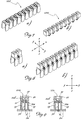
- Both the conducting body 10 and the insulating body 20 may also be formed as strips 100,200 ( Fig. 7a,7b ) so as to form complete jumpers in strip form ( Figs. 8a,8b ) from which the user may separate single jumpers or jumpers formed by several conducting and insulating sub-bodies as required, by simply breaking the tongue 14 between two adjacent sub-bodies of the conducting body 10 along each of the easy separation incisions 15 and separating the membrane 24 and the arched lug 25 of the insulating body 20 on the appropriate side of the connecting membrane.
- the insulating body 200 in the form of a strip will in fact comprise respective arched lugs 25 between each insulating sub-body and the adjacent sub-body.
- the insulating body with hole 22 having different diameters d1 and d2 respectively corresponding to the diameter of the head or the threaded shank of the screw 30 and the associated ribs 23, upon insertion of the screw inside the holes of the jumper a relative interference with friction is created between the head or the shank - or between the head and the shank - of the screw and the respective insulating sub-body 21, which retains the screw inside the seat, preventing separation thereof also in the case of impacts and/or over-loosening by the user.
- the strip comprises twelve jumpers, a number which allows the separation of various jumpers or multiples of jumpers (2,3,4), limiting the amount of unusable waste.
- both the insulating body and the conducting body may be manually separated/split to size respectively along the guiding incisions of the central membrane, which joins together two adjacent insulating sub-bodies, and along easy breakage lines of the conducting bodies defined by the pairs of oppositely arranged V-shaped incisions which, in addition to allowing manual breakage, also ensure precise breakage corresponding to that of the insulating body so as to allow renewed joining together of the two parts cut to size.
- the jumper according to the invention may be applied onto a conducting bar 1 of a switchboard terminal block (not shown) in two stages:
Landscapes
- Connections Effected By Soldering, Adhesion, Or Permanent Deformation (AREA)
- Connections Arranged To Contact A Plurality Of Conductors (AREA)
Abstract
- a conducting body (10) comprising at least two sub-bodies (11), each with a shape substantially in the form of an overturned "U"
- an insulating body (20) comprising at least two sub-bodies (21) with a substantially parallelepiped shape made of suitable insulating material, connected together longitudinally (X-X) by a vertical membrane with a reduced thickness in the transverse direction (Y-Y);
wherein the insulating body has a plane for coupling with the conducting body (10),
which coupling plane comprises, between each sub-body (21) and the adjacent sub-body (21), a pair of arched lugs (25) arranged opposite each other in the transverse direction (Y-Y) and extending in the longitudinal direction (X-X) so that the respective vertical arms (25a) are respectively connected to each one of the adjacent sub-bodies (21);
each arched lug (25) having a tooth (25b) extending in the transverse direction (Y-Y) towards the inside of the insulating body (20) in the empty space between the two sub-bodies (21), said arched lugs (25) with tooth (25b) allowing relative reversible engagement of the insulating body (20) and the conducting body (10).
Description
- The present invention relates to an insulated jumper of the screw type in particular for terminal blocks of switchboards and the like.
- It is known, in the technical sector relating to terminal blocks for switchboards, that there exists the need to connect together two terminals situated alongside each other on the switchboard, in order to perform the required electrical connection.
- Also known are jumpers which are made of conductive material and which are designed for this purpose; among the known jumpers the following in particular may be distinguished:
- jumpers which are configured with two elastic jaws designed to form the element for engagement in a seat of the terminal block with corresponding electrical contact in the transverse direction provided by the elastic force which pushes the contact plates against the walls of a hole in a conducting bar for connecting together the opposite terminals of the terminal block (
EP 1 876 674 - screw-type jumpers by means of which electrical contact occurs in the vertical direction as a result of the foot of the jumper making contact on a conducting bar connecting together the opposite terminals of the terminal block, said contact being achieved by tightening a screw inside the female thread of a hole formed in said bar.
- These screw-type jumpers, although performing their function, nevertheless have a number of drawbacks arising in particular from the difficulty of separating a pair of jumpers from a strip of a plurality of said jumpers, while limiting the number of jumpers which are left singly attached to the strip and are no longer usable.
- In addition the known jumpers have the drawback due to the fact that the locking screw is not electrically insulated from the outside and also tends to come loose owing to the vibrations which are generated during the movements of the terminal or owing to positioning in unsuitable environments.
US 1 952 554 discloses a plural unit terminal block integrally formed simulating a plurality of single unit blocks integrally connected together by easily frangible means of relatively small cross-section between adjacent blocks and substantially sharp V-like impressions in the frangible means extending transversely thereof for promoting the certainty of start of a frangible means fracture at a definite place. -
WO 2004/105 188 A1 discloses an insulating terminal cover which has through holes and snapping means for coupling to an insulating housing of a single unit terminal. - The technical problem posed is therefore that of providing electrical connection jumpers of the screw type, in particular for terminal blocks of switchboards, designed to be electrically insulated from the outside and ensure the insulation of the conducting parts so as to prevent them from coming into contact with the user and/or with foreign bodies, causing short-circuiting of the installation.
- In connection with this problem it is also required that this jumper should preferably be able to be easily cut to size from multiple strips, have small overall dimensions, be easy and inexpensive to produce and assemble and be able to be used at any user location without the aid of cutting means for dividing/separating the jumpers.
- These results are obtained according to the present invention by an electrical connection jumper of the screw type in particular for terminal blocks of switchboards and the like according to the characteristic features of
Claim 1. - In greater detail, the invention relates to an electrical connection jumper of the screw type, in particular for terminal blocks of switchboards, extending in a longitudinal lengthwise direction (X-X), transverse widthwise direction (Y-Y) and vertical direction (Z-Z) perpendicular to the preceding directions, and comprising:
- a conducting body comprising at least two sub-bodies, each with a shape substantially in the form of an overturned "U" with
- --) a respective head lying in a plane parallel to the longitudinal direction and transverse direction and
- --) respective contact plates lying in planes parallel to the longitudinal direction and vertical direction (Z-Z) and arranged opposite each other in the transverse direction relative to the head;
- --) each head having a vertical through-hole; the at least two conducting sub-bodies being connected in the longitudinal direction by means of a tongue;
- an insulating body comprising at least two sub-bodies with a substantially parallelepiped shape made of suitable insulating material, connected together longitudinally by a vertical membrane with a small thickness in the transverse direction;
each insulating sub-body being passed through by a respective vertical through-hole;
wherein the insulating body has a plane for coupling with the conducting body, which coupling plane comprises, between each sub-body and the adjacent sub-body, a pair of arched lugs situated opposite each other in the transverse direction and extending in the longitudinal direction so that the respective vertical arms are respectively connected to each one of the adjacent sub-bodies;
each arched lug has a tooth extending in the transverse direction towards the inside of the insulating body in the empty space between the two sub-bodies, said arched lugs with tooth allowing relative reversible engagement of the insulating body and the conducting body; - at least two screws for performing fixing to a terminal block, each being suitable for insertion into the through-hole of a respective sub-body of the insulating sub-bodies.
- Further details may be obtained from the following description of a non-limiting example of embodiment of the subject of the present invention, provided with reference to the accompanying drawings, in which:
-
Figure 1 : shows an exploded view of a screw-type jumper according to the present invention; -
Figure 2 : shows a perspective view of the conducting body of the jumper according to the present invention; -
Figure 3 : shows a front view of the conducting body according toFigure 2 ; -
Figure 4 : shows a top plan view of the insulating body of the jumper according to the present invention; -
Figure 5 : shows a cross-section along the plane indicated by V-V of the insulating body according toFigure 4 ; -
Figure 6 : shows a partially sectioned side view of the insulating body of a jumper according to the present invention; -
Figures 7a,7b : show perspective views of a strip of conducting sub-bodies and a strip of insulating sub-bodies, respectively; -
Figures 8a,8b : show a perspective view of a jumper and a multiple jumper in strip form according to the invention, respectively, and -
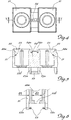
Figures 9a,9b : show a vertical section through a jumper according to the invention applied onto a conducting bar for connecting a terminal block (not shown) in the mounted condition fixed by means of a screw. - As shown and assuming solely for the sake of easier description and without any limiting meaning a set of three reference axes, extending in a longitudinal lengthwise direction X-X of the jumper, transverse widthwise direction Y-Y of the jumper and vertical direction Z-Z perpendicular to the other two directions and parallel to the direction of extension of a screw for fixing to a terminal block, the jumper for terminal blocks of switchboards according to the present invention comprises basically: a conducting
body 10, aninsulating body 20 and ascrew 30. - In greater detail:
- the conducting body 10 (
Fig. 1 ) comprises twosub-bodies 11 with a shape substantially in the form of an overturned "U" withrespective head 12 lying in a plane X-Y andcontact plates 13 lying in planes X-Z situated opposite each other relative to thehead 12; eachhead 12 has a through-hole 12a; the twosub-bodies 11 are connected together in the longitudinal direction X-X by means of atongue 14; preferably thetongue 14 has two V-shaped incisions 15 respectively formed on the top surface 14a and bottom surface 14b of said tongue, being situated opposite each other and extending parallel to the transverse direction Y-Y; the two incisions form preferential breakage lines for the jumper, as shown inFigs. 2 and 3 and as will become clear below.
Preferably, the two edges of thetongue 14 parallel to the longitudinal direction X-X have achamfer 16 inclined from the plane of the tongue downwards in the vertical direction Z-Z, with the orientation shown in the figure. - the insulating body 20 (
Figs. 4,5,6 ) comprises twosub-bodies 21 with a substantially parallelepiped - in the example cube-like - shape, made of suitable insulating material and connected together longitudinally (X-X) by avertical membrane 24 having a reduced thickness in the transverse direction Y-Y; preferably, the reduced-thickness membrane has at its respective ends two guide lines, so as to predefine a respective point for easy separation which may be performed preferably manually (for example by means of folding along the guide line) or using a standard cutting tool. - The two
sub-bodies 21 are crossed by a through-hole 22 which preferably has (Fig. 6 ) atop section 22a, in the vertical direction Z-Z, with a greater diameter d1 and a bottom section 22b, coaxial in the same vertical direction Z-Z, with a smaller diameter d2. - At least two
ribs 23 are also preferably provided inside thehole 22 and also engage within the diameter of the head so as to produce greater friction such that the screw cannot come loose; examples of the arrangement of theribs 23 are three ribs arranged with angular spacing of 120° or, as in the example shown inFig. 5 , fourribs 23 arranged with angular spacing of 90°. - Preferably, the diameter d2 of the top section 22b substantially corresponds to the diameter of the
head 31 of thescrew 30. - Preferably, the diameter d2 of the bottom section 22b corresponds to the internal diameter of the
thread 32a on theshank 32 of thescrew 30. - The bottom surfaces of the
insulating sub-bodies 21 define, during use, a plane for coupling with the conductingbody 10, which is substantially parallel to the plane (X-Y) of theheads 12 of the conducting sub-bodies. - The plane for coupling of the
insulating body 20 with theconducting body 10 has, preferably along its longitudinal edges, situated on the outside in the transverse direction Y-Y (Fig. 5 ), a pair ofarched lugs 25 situated opposite each other and extending in the longitudinal direction X-X so that the respectivevertical arms 25 are respectively connected to the first and secondadjacent sub-bodies 21. - Each
arched lug 25 also has (Fig. 6 ) a tooth 25b extending in the transverse direction Y-Y towards the inside of theconducting body 20 in the empty space situated between the two sub-bodies. Preferably, the twoarched lugs 25 and the tooth 25b are elastically deformable so as to facilitate engagement of theinsulating body 20 with thetongue 24 connecting the twosub-bodies 11 of the conductingbody 10; the engagement is then further facilitated by thelongitudinal chamfer 16 of thetongue 14, said chamfer allowing improved sliding with elastic deformation of thearm 25a with tooth 25b. - With this configuration of the conducting
body 10 and insulatingbody 20, assembly of the jumper according to the invention is performed by means of engagement of theinsulating body 20 with the conductingbody 10 by means of a relative pressure which causes the temporary deformation of thearched lugs 25 which, expanding, allow the respective tooth 25b to pass below the connectingtongue 14 of the conductingsub-bodies 11 of the conducting body, the elastic return of the arched lugs into the rest position causing stable engagement of the insulating body with the conducting body. - The particular structure of the two bodies, i.e. conducting
body 10 and insulatingbody 20, allows precise and repeatable joining together of the two parts with coaxial centring of the respective holes for precise insertion of thescrew 30. - Both the conducting
body 10 and the insulatingbody 20 may also be formed as strips 100,200 (Fig. 7a,7b ) so as to form complete jumpers in strip form (Figs. 8a,8b ) from which the user may separate single jumpers or jumpers formed by several conducting and insulating sub-bodies as required, by simply breaking thetongue 14 between two adjacent sub-bodies of the conductingbody 10 along each of theeasy separation incisions 15 and separating themembrane 24 and thearched lug 25 of theinsulating body 20 on the appropriate side of the connecting membrane. - The
insulating body 200 in the form of a strip will in fact comprise respectivearched lugs 25 between each insulating sub-body and the adjacent sub-body. According to the preferred embodiment of the insulating body withhole 22 having different diameters d1 and d2 respectively corresponding to the diameter of the head or the threaded shank of thescrew 30 and the associatedribs 23, upon insertion of the screw inside the holes of the jumper a relative interference with friction is created between the head or the shank - or between the head and the shank - of the screw and the respective insulatingsub-body 21, which retains the screw inside the seat, preventing separation thereof also in the case of impacts and/or over-loosening by the user. - According to a preferred embodiment it is also envisaged that the strip comprises twelve jumpers, a number which allows the separation of various jumpers or multiples of jumpers (2,3,4), limiting the amount of unusable waste.
- It is therefore clear how with the electrical connection screw-type jumper for switchboard terminal blocks according to the present invention it is possible to provide conducting jumpers which are assembled during production complete with insulating body and screw and are therefore ready for use by the end user; it also possible to ensure easy formation and/or separation/splitting to size of the said jumper as well as prevent the screw from coming loose since it is always retained, as a result of friction, by the insulating body.
- In particular, it is possible to provide the strips pre-assembled, the end user merely having to separate the insulating body, with corresponding screw not protruding therefrom, from the conducting body; both the insulating body and the conducting body may be manually separated/split to size respectively along the guiding incisions of the central membrane, which joins together two adjacent insulating sub-bodies, and along easy breakage lines of the conducting bodies defined by the pairs of oppositely arranged V-shaped incisions which, in addition to allowing manual breakage, also ensure precise breakage corresponding to that of the insulating body so as to allow renewed joining together of the two parts cut to size.
- As shown in
Fig. 9 the jumper according to the invention may be applied onto a conductingbar 1 of a switchboard terminal block (not shown) in two stages: - arranging the jumper with
screw 30 inserted in the vertical direction so that theshank 32 protrudes from the bottom edge of thehole 22 only by a small amount (a couple of threads); - mounting the jumper on the bar 1 (
Figure 9a ) with thescrew 32 resting inside thehole 2 of thebar 1 and tightening the screw inside thehole 2 of the bar 1 (Fig. 9b ) so as to compress thecontact plates 13 of the conducting body against thebar 1, ensuring the required electrical contact.
Claims (10)
- Electrical connection jumper, of the screw type in particular for switchboard terminal blocks, extending in a longitudinal lengthwise direction (X-X), transverse widthwise direction (Y-Y) and vertical direction (Z-Z) perpendicular to the preceding directions, and comprising:- a conducting body (10) comprising at least two sub-bodies (11), each substantially in the form of an overturned "U" having--) a respective head (12) lying in a plane (X-Y) parallel to the longitudinal direction (X-X) and transverse direction (Y-Y) and--) respective contact plates (13) lying in planes (X-Z) parallel to the longitudinal direction (X-X) and vertical direction (Z-Z) and situated opposite each other in the transverse direction (Y-Y) relative to the head (12);--) each head (12) having a through-hole (12a) in the vertical direction (Z-Z);
the at least two conducting sub-bodies (11) being connected in the longitudinal direction (X-X) by means of a tongue (14);- an insulating body (20) comprising at least two sub-bodies (21) with a substantially parallelepiped shape, made of suitable insulating material and connected together longitudinally (X-X) by a vertical membrane (24) of reduced thickness in the transverse direction (Y-Y);
each insulating sub-body (21) having, passing through it, a respective vertical through-hole (22) ;
wherein the insulating body (20) has a plane for coupling with the conducting body (10), which coupling plane comprises, between each sub-body (21) and the adjacent sub-body (21), a pair of arched lugs (25) situated opposite each other in the transverse direction (Y-Y) and extending in the longitudinal direction (X-X) so that the respective vertical arms (25a) are respectively connected to each one of the adjacent sub-bodies (21);
each arched lug (25) having a tooth (25b) extending in the transverse direction (Y-Y) towards the inside of the insulating body (20) in the empty space between the two sub-bodies (21), said arched lug (25) with tooth (25b) allowing relative reversible engagement of the insulating body (20) and the conducting body (10);- at least two screws (30) for performing fixing to a terminal block, each being suitable for insertion into the through-hole (22) of a respective sub-body of the insulating sub-bodies (21). - Jumper according to Claim 1, characterized in that the hole (22) in the sub-bodies of the insulating body (20) has a top section (22a), in the vertical direction (Z-Z), with a larger diameter (d1), and a bottom section (22b), coaxial in the same vertical direction (Z-Z), with a smaller diameter (d2).
- Jumper according to Claim 1 or 2, characterized in that the connecting tongue (14) between the at least two conducting sub-bodies (11) has incisions (15) in the form of a V formed in the top surface (14a) and bottom surface (14b) of the said tongue, situated opposite each other and extending parallel to the transverse direction (Y-Y) so as to form preferential breakage lines of the jumper.
- Jumper according to any one of the preceding claims, characterized in that the two edges of the tongue (14) parallel to the longitudinal direction (X-X) have a chamfer (16) inclined from the plane of the tongue downwards in the vertical direction (Z-Z).
- Jumper according to Claim 2, 3 or 4, characterized in that the diameter (d1) of the top section (22a) of the hole (22) in the insulating sub-body (21) corresponds to the diameter of the head (31) of the screw (30).
- Jumper according to any one of Claims 2 to 5, characterized in that the diameter (d2) of the bottom section (22b) of the hole (22) in the insulating sub-body (21) corresponds to the internal diameter of the thread (32) of the respective screw (30).
- Jumper according to any one of the preceding claims, characterized in that the hole (22) has internally at least two vertical ribs (23) designed for frictional engagement with the head of the screw (30), preferably three ribs (23) arranged with an angular spacing of 120° or four ribs (23) arranged with an angular spacing of 90°.
- Jumper according to any one of the preceding claims, characterized in that it is formed as a strip of suitable length in the longitudinal direction (X-X).
- Jumper according to Claim 8, characterized in that said strip has twelve conducting sub-bodies joined together by respective connecting tongues (14).
- Jumper according to any of the preceding claims characterized in that said pairs of opposite arched lugs (25) extend from the longitudinal edges, situated on the outside in the transverse direction (Y-Y), of the plane for coupling with the conducting body.
Priority Applications (1)
| Application Number | Priority Date | Filing Date | Title |
|---|---|---|---|
| PL16152028T PL3051633T3 (en) | 2015-01-27 | 2016-01-20 | Insulated jumper of the screw type in particular for terminal blocks of switchboards |
Applications Claiming Priority (1)
| Application Number | Priority Date | Filing Date | Title |
|---|---|---|---|
| ITMI20150093 | 2015-01-27 |
Publications (2)
| Publication Number | Publication Date |
|---|---|
| EP3051633A1 true EP3051633A1 (en) | 2016-08-03 |
| EP3051633B1 EP3051633B1 (en) | 2018-06-20 |
Family
ID=52774352
Family Applications (1)
| Application Number | Title | Priority Date | Filing Date |
|---|---|---|---|
| EP16152028.3A Active EP3051633B1 (en) | 2015-01-27 | 2016-01-20 | Insulated jumper of the screw type in particular for terminal blocks of switchboards |
Country Status (3)
| Country | Link |
|---|---|
| US (1) | US9748672B2 (en) |
| EP (1) | EP3051633B1 (en) |
| PL (1) | PL3051633T3 (en) |
Cited By (1)
| Publication number | Priority date | Publication date | Assignee | Title |
|---|---|---|---|---|
| EP3671961A1 (en) * | 2018-12-18 | 2020-06-24 | Kamstrup A/S | Terminal clamp with screw lock |
Citations (4)
| Publication number | Priority date | Publication date | Assignee | Title |
|---|---|---|---|---|
| US1952554A (en) | 1930-09-04 | 1934-03-27 | Railroad Accessories Corp | Terminal block |
| EP0893859A2 (en) * | 1997-07-23 | 1999-01-27 | FINDER S.p.A. | Modular comb connector for relay interfaces |
| WO2004105188A1 (en) | 2003-04-19 | 2004-12-02 | Abb Patent Gmbh | Connecting strip for a terminal arrangement for a low-level distributor and/or a distribution panel of an electric low-voltage switching station |
| EP1876674A1 (en) | 2006-07-07 | 2008-01-09 | Morsettitalia S.p.A. | Insulated jumper in particular for terminal blocks of switchboards |
Family Cites Families (30)
| Publication number | Priority date | Publication date | Assignee | Title |
|---|---|---|---|---|
| US1579400A (en) * | 1923-06-05 | 1926-04-06 | Robert V Dunbar | Terminal block |
| US1961111A (en) * | 1930-03-24 | 1934-05-29 | Western Union Telegraph Co | Switchboard terminal block |
| US2411014A (en) * | 1944-06-21 | 1946-11-12 | Us Instr Corp | Terminal block |
| US2900618A (en) * | 1957-05-02 | 1959-08-18 | John I Paulding Inc | Contact terminal |
| US3665376A (en) * | 1970-12-23 | 1972-05-23 | Teledyne Mid America Corp | Terminal block and method of making the same |
| US3775733A (en) * | 1971-04-12 | 1973-11-27 | Underwriters Safety Device Co | Terminal block and terminal connector |
| US3728656A (en) * | 1972-06-26 | 1973-04-17 | Gte Sylvania Inc | Transormer and terminal assembly |
| DE2500141A1 (en) * | 1974-01-23 | 1975-07-24 | Gen Signal Corp | ELECTRICAL CONNECTOR WITH VARIABLE LENGTH |
| FR2393448A1 (en) * | 1976-08-18 | 1978-12-29 | Wago Kontakttechnik Gmbh | ELECTRICAL CONNECTION OR CONNECTION DEVICE |
| US4130331A (en) * | 1976-12-09 | 1978-12-19 | Amp Incorporated | Solderless connector for terminating a magnet wire or the like |
| FR2620578B1 (en) * | 1987-09-11 | 1990-01-05 | Telemecanique Electrique | ELECTRICAL CONNECTION DEVICE FOR TERMINAL OF ELECTRICAL APPARATUS, CIRCUIT BREAKER THUS EQUIPPED, AND ASSEMBLY OF CONSTITUENTS RELATING THERETO |
| US5149278A (en) * | 1991-02-22 | 1992-09-22 | Psi Telecommunications, Inc. | Terminal block |
| DE4132407C2 (en) * | 1991-09-26 | 2000-11-02 | Wago Verwaltungs Gmbh | Common connection for electr. Distribution systems |
| US5905230A (en) * | 1995-08-15 | 1999-05-18 | Thomas & Betts Corporation | Self tapping screw for use with an electrical connector |
| US5915998A (en) * | 1996-06-19 | 1999-06-29 | Erico International Corporation | Electrical connector and method of making |
| US5669788A (en) * | 1996-09-18 | 1997-09-23 | Allen-Bradley Company, Inc. | Screwless terminal block linking apparatus |
| US6222717B1 (en) * | 1997-05-15 | 2001-04-24 | 3M Innovative Properties Co. | Multi-chamber telecommunications terminal block with linking module |
| US6157287A (en) * | 1999-03-03 | 2000-12-05 | Cooper Technologies Company | Touch safe fuse module and holder |
| US6696969B2 (en) * | 2000-06-30 | 2004-02-24 | Cooper Technologies, Inc. | Compact fused disconnect switch |
| DE10351289B4 (en) * | 2003-08-13 | 2008-01-10 | Phoenix Contact Gmbh & Co. Kg | Jumper for electrical connection and / or connection terminals |
| US7458840B2 (en) * | 2004-09-15 | 2008-12-02 | 3M Innovative Properties Company | Cap configured to removably connect to an insulation displacement connector block |
| KR200376471Y1 (en) * | 2004-12-09 | 2005-03-10 | 엘지산전 주식회사 | A Terminal Connecting Device of the Electronic Contactor |
| US7458845B2 (en) * | 2006-06-15 | 2008-12-02 | Sound Sources Technolog, Inc | Terminal assembly for selectively coupling loads in parallel and in series |
| ITMI20061496A1 (en) * | 2006-07-28 | 2008-01-29 | Morsettitalia Spa | TERMINAL WITH U-SHAPED CONDUCTOR FOR THE CONNECTION OF ELECTRIC WIRES |
| EP1953869B1 (en) * | 2007-02-05 | 2014-07-30 | Morsettitalia S.p.A. | Terminal block with jaw part for engagement with the flat pin of movable electric contacts |
| ITMI20070186A1 (en) * | 2007-02-05 | 2008-08-06 | Morsettitalia Spa | PROCEDURE FOR THE PRODUCTION OF CONTACT ELEMENTS OF LAMINATED FURNITURE AND CONTACT ELEMENTS COMPLETED. |
| ITMI20071390A1 (en) * | 2007-07-12 | 2009-01-13 | Morsettitalia Spa | TIGHTENING ELEMENT WITH L-SHAPED CONDUCTOR ELEMENT FOR THE CONNECTION OF ELECTRIC WIRES |
| DE102011113333B4 (en) * | 2011-09-15 | 2014-07-03 | Phoenix Contact Gmbh & Co. Kg | Electrical terminal block and terminal block |
| US8651902B2 (en) * | 2012-03-07 | 2014-02-18 | Dinkle Enterprise Co., Ltd. | Wire-grasping structure for terminal block |
| PL3054533T3 (en) * | 2015-02-05 | 2020-06-29 | Morsettitalia S.P.A. | Base terminal block and auxiliary terminal block for switchboards and two-tier terminal block assembly comprising base terminal block and auxiliary terminal block |
-
2016
- 2016-01-20 PL PL16152028T patent/PL3051633T3/en unknown
- 2016-01-20 EP EP16152028.3A patent/EP3051633B1/en active Active
- 2016-01-27 US US15/007,441 patent/US9748672B2/en active Active
Patent Citations (4)
| Publication number | Priority date | Publication date | Assignee | Title |
|---|---|---|---|---|
| US1952554A (en) | 1930-09-04 | 1934-03-27 | Railroad Accessories Corp | Terminal block |
| EP0893859A2 (en) * | 1997-07-23 | 1999-01-27 | FINDER S.p.A. | Modular comb connector for relay interfaces |
| WO2004105188A1 (en) | 2003-04-19 | 2004-12-02 | Abb Patent Gmbh | Connecting strip for a terminal arrangement for a low-level distributor and/or a distribution panel of an electric low-voltage switching station |
| EP1876674A1 (en) | 2006-07-07 | 2008-01-09 | Morsettitalia S.p.A. | Insulated jumper in particular for terminal blocks of switchboards |
Cited By (1)
| Publication number | Priority date | Publication date | Assignee | Title |
|---|---|---|---|---|
| EP3671961A1 (en) * | 2018-12-18 | 2020-06-24 | Kamstrup A/S | Terminal clamp with screw lock |
Also Published As
| Publication number | Publication date |
|---|---|
| PL3051633T3 (en) | 2018-11-30 |
| EP3051633B1 (en) | 2018-06-20 |
| US20160218448A1 (en) | 2016-07-28 |
| US9748672B2 (en) | 2017-08-29 |
Similar Documents
| Publication | Publication Date | Title |
|---|---|---|
| US8647159B2 (en) | Apparatus and method for effecting electrical termination with a plurality of types of termination structures | |
| JP6793727B2 (en) | Contact elements and multiple contact tulips | |
| KR102146318B1 (en) | Terminal for contacting an electrical conductor | |
| CN110679042B (en) | Apparatus and method for connecting a first electric wire with a second electric wire | |
| JPS5925341B2 (en) | Cable connection tool with multiple connection members | |
| EP2670001B1 (en) | Insulation displacement terminal | |
| CN102394394A (en) | Connector | |
| EP1876674A1 (en) | Insulated jumper in particular for terminal blocks of switchboards | |
| EP3276757A1 (en) | Busbar connector and set consisting of two complementary busbar connectors and metal troughs containing power conductor profile | |
| US20160111799A1 (en) | Battery Terminal | |
| JP2019079887A (en) | Din rail attachment structure of electrical appliance and socket | |
| JP2014002846A (en) | Joint connector extension structure and joint connector | |
| US8262404B2 (en) | Terminal block and contact element for telecommunications and data systems | |
| US4013332A (en) | Electrical connector | |
| US2211591A (en) | Attachment plug cap | |
| EP3051633B1 (en) | Insulated jumper of the screw type in particular for terminal blocks of switchboards | |
| US6716055B1 (en) | Electrical connector for connecting a branched circuit to a main power source | |
| CZ20011158A3 (en) | Coupling for overhead cable | |
| US9184515B1 (en) | Terminal blocks for printed circuit boards | |
| KR101103797B1 (en) | Electrical connection terminal block | |
| DE102012000079B4 (en) | Electrical mandrel connector and its use | |
| KR20100121950A (en) | Connector having joint terminal | |
| US9819106B2 (en) | Male strip connector | |
| HK75893A (en) | Cutting and clamping terminal for an electrical conductor | |
| EP2897228A1 (en) | Terminal device and electric outlet using same |
Legal Events
| Date | Code | Title | Description |
|---|---|---|---|
| PUAI | Public reference made under article 153(3) epc to a published international application that has entered the european phase |
Free format text: ORIGINAL CODE: 0009012 |
|
| AK | Designated contracting states |
Kind code of ref document: A1 Designated state(s): AL AT BE BG CH CY CZ DE DK EE ES FI FR GB GR HR HU IE IS IT LI LT LU LV MC MK MT NL NO PL PT RO RS SE SI SK SM TR |
|
| AX | Request for extension of the european patent |
Extension state: BA ME |
|
| STAA | Information on the status of an ep patent application or granted ep patent |
Free format text: STATUS: REQUEST FOR EXAMINATION WAS MADE |
|
| 17P | Request for examination filed |
Effective date: 20170124 |
|
| RBV | Designated contracting states (corrected) |
Designated state(s): AL AT BE BG CH CY CZ DE DK EE ES FI FR GB GR HR HU IE IS IT LI LT LU LV MC MK MT NL NO PL PT RO RS SE SI SK SM TR |
|
| GRAP | Despatch of communication of intention to grant a patent |
Free format text: ORIGINAL CODE: EPIDOSNIGR1 |
|
| STAA | Information on the status of an ep patent application or granted ep patent |
Free format text: STATUS: GRANT OF PATENT IS INTENDED |
|
| INTG | Intention to grant announced |
Effective date: 20180119 |
|
| RIC1 | Information provided on ipc code assigned before grant |
Ipc: H01R 4/30 20060101ALN20180108BHEP Ipc: H01R 4/34 20060101ALN20180108BHEP Ipc: H01R 31/08 20060101ALN20180108BHEP Ipc: H01R 9/24 20060101AFI20180108BHEP |
|
| INTG | Intention to grant announced |
Effective date: 20180119 |
|
| GRAS | Grant fee paid |
Free format text: ORIGINAL CODE: EPIDOSNIGR3 |
|
| GRAA | (expected) grant |
Free format text: ORIGINAL CODE: 0009210 |
|
| STAA | Information on the status of an ep patent application or granted ep patent |
Free format text: STATUS: THE PATENT HAS BEEN GRANTED |
|
| AK | Designated contracting states |
Kind code of ref document: B1 Designated state(s): AL AT BE BG CH CY CZ DE DK EE ES FI FR GB GR HR HU IE IS IT LI LT LU LV MC MK MT NL NO PL PT RO RS SE SI SK SM TR |
|
| REG | Reference to a national code |
Ref country code: GB Ref legal event code: FG4D |
|
| REG | Reference to a national code |
Ref country code: IE Ref legal event code: FG4D |
|
| REG | Reference to a national code |
Ref country code: AT Ref legal event code: REF Ref document number: 1011223 Country of ref document: AT Kind code of ref document: T Effective date: 20180715 |
|
| REG | Reference to a national code |
Ref country code: DE Ref legal event code: R096 Ref document number: 602016003595 Country of ref document: DE |
|
| REG | Reference to a national code |
Ref country code: CH Ref legal event code: NV Representative=s name: DR. LUSUARDI AG, CH |
|
| REG | Reference to a national code |
Ref country code: NL Ref legal event code: MP Effective date: 20180620 |
|
| PG25 | Lapsed in a contracting state [announced via postgrant information from national office to epo] |
Ref country code: FI Free format text: LAPSE BECAUSE OF FAILURE TO SUBMIT A TRANSLATION OF THE DESCRIPTION OR TO PAY THE FEE WITHIN THE PRESCRIBED TIME-LIMIT Effective date: 20180620 Ref country code: LT Free format text: LAPSE BECAUSE OF FAILURE TO SUBMIT A TRANSLATION OF THE DESCRIPTION OR TO PAY THE FEE WITHIN THE PRESCRIBED TIME-LIMIT Effective date: 20180620 Ref country code: BG Free format text: LAPSE BECAUSE OF FAILURE TO SUBMIT A TRANSLATION OF THE DESCRIPTION OR TO PAY THE FEE WITHIN THE PRESCRIBED TIME-LIMIT Effective date: 20180920 Ref country code: SE Free format text: LAPSE BECAUSE OF FAILURE TO SUBMIT A TRANSLATION OF THE DESCRIPTION OR TO PAY THE FEE WITHIN THE PRESCRIBED TIME-LIMIT Effective date: 20180620 Ref country code: NO Free format text: LAPSE BECAUSE OF FAILURE TO SUBMIT A TRANSLATION OF THE DESCRIPTION OR TO PAY THE FEE WITHIN THE PRESCRIBED TIME-LIMIT Effective date: 20180920 |
|
| REG | Reference to a national code |
Ref country code: LT Ref legal event code: MG4D |
|
| PG25 | Lapsed in a contracting state [announced via postgrant information from national office to epo] |
Ref country code: GR Free format text: LAPSE BECAUSE OF FAILURE TO SUBMIT A TRANSLATION OF THE DESCRIPTION OR TO PAY THE FEE WITHIN THE PRESCRIBED TIME-LIMIT Effective date: 20180921 Ref country code: HR Free format text: LAPSE BECAUSE OF FAILURE TO SUBMIT A TRANSLATION OF THE DESCRIPTION OR TO PAY THE FEE WITHIN THE PRESCRIBED TIME-LIMIT Effective date: 20180620 Ref country code: RS Free format text: LAPSE BECAUSE OF FAILURE TO SUBMIT A TRANSLATION OF THE DESCRIPTION OR TO PAY THE FEE WITHIN THE PRESCRIBED TIME-LIMIT Effective date: 20180620 Ref country code: LV Free format text: LAPSE BECAUSE OF FAILURE TO SUBMIT A TRANSLATION OF THE DESCRIPTION OR TO PAY THE FEE WITHIN THE PRESCRIBED TIME-LIMIT Effective date: 20180620 |
|
| REG | Reference to a national code |
Ref country code: AT Ref legal event code: MK05 Ref document number: 1011223 Country of ref document: AT Kind code of ref document: T Effective date: 20180620 |
|
| PG25 | Lapsed in a contracting state [announced via postgrant information from national office to epo] |
Ref country code: NL Free format text: LAPSE BECAUSE OF FAILURE TO SUBMIT A TRANSLATION OF THE DESCRIPTION OR TO PAY THE FEE WITHIN THE PRESCRIBED TIME-LIMIT Effective date: 20180620 |
|
| PG25 | Lapsed in a contracting state [announced via postgrant information from national office to epo] |
Ref country code: AT Free format text: LAPSE BECAUSE OF FAILURE TO SUBMIT A TRANSLATION OF THE DESCRIPTION OR TO PAY THE FEE WITHIN THE PRESCRIBED TIME-LIMIT Effective date: 20180620 Ref country code: EE Free format text: LAPSE BECAUSE OF FAILURE TO SUBMIT A TRANSLATION OF THE DESCRIPTION OR TO PAY THE FEE WITHIN THE PRESCRIBED TIME-LIMIT Effective date: 20180620 Ref country code: IS Free format text: LAPSE BECAUSE OF FAILURE TO SUBMIT A TRANSLATION OF THE DESCRIPTION OR TO PAY THE FEE WITHIN THE PRESCRIBED TIME-LIMIT Effective date: 20181020 Ref country code: CZ Free format text: LAPSE BECAUSE OF FAILURE TO SUBMIT A TRANSLATION OF THE DESCRIPTION OR TO PAY THE FEE WITHIN THE PRESCRIBED TIME-LIMIT Effective date: 20180620 Ref country code: SK Free format text: LAPSE BECAUSE OF FAILURE TO SUBMIT A TRANSLATION OF THE DESCRIPTION OR TO PAY THE FEE WITHIN THE PRESCRIBED TIME-LIMIT Effective date: 20180620 Ref country code: RO Free format text: LAPSE BECAUSE OF FAILURE TO SUBMIT A TRANSLATION OF THE DESCRIPTION OR TO PAY THE FEE WITHIN THE PRESCRIBED TIME-LIMIT Effective date: 20180620 |
|
| PG25 | Lapsed in a contracting state [announced via postgrant information from national office to epo] |
Ref country code: SM Free format text: LAPSE BECAUSE OF FAILURE TO SUBMIT A TRANSLATION OF THE DESCRIPTION OR TO PAY THE FEE WITHIN THE PRESCRIBED TIME-LIMIT Effective date: 20180620 Ref country code: ES Free format text: LAPSE BECAUSE OF FAILURE TO SUBMIT A TRANSLATION OF THE DESCRIPTION OR TO PAY THE FEE WITHIN THE PRESCRIBED TIME-LIMIT Effective date: 20180620 |
|
| REG | Reference to a national code |
Ref country code: DE Ref legal event code: R097 Ref document number: 602016003595 Country of ref document: DE |
|
| PLBE | No opposition filed within time limit |
Free format text: ORIGINAL CODE: 0009261 |
|
| STAA | Information on the status of an ep patent application or granted ep patent |
Free format text: STATUS: NO OPPOSITION FILED WITHIN TIME LIMIT |
|
| 26N | No opposition filed |
Effective date: 20190321 |
|
| PG25 | Lapsed in a contracting state [announced via postgrant information from national office to epo] |
Ref country code: DK Free format text: LAPSE BECAUSE OF FAILURE TO SUBMIT A TRANSLATION OF THE DESCRIPTION OR TO PAY THE FEE WITHIN THE PRESCRIBED TIME-LIMIT Effective date: 20180620 |
|
| PG25 | Lapsed in a contracting state [announced via postgrant information from national office to epo] |
Ref country code: MC Free format text: LAPSE BECAUSE OF FAILURE TO SUBMIT A TRANSLATION OF THE DESCRIPTION OR TO PAY THE FEE WITHIN THE PRESCRIBED TIME-LIMIT Effective date: 20180620 Ref country code: SI Free format text: LAPSE BECAUSE OF FAILURE TO SUBMIT A TRANSLATION OF THE DESCRIPTION OR TO PAY THE FEE WITHIN THE PRESCRIBED TIME-LIMIT Effective date: 20180620 |
|
| PG25 | Lapsed in a contracting state [announced via postgrant information from national office to epo] |
Ref country code: LU Free format text: LAPSE BECAUSE OF NON-PAYMENT OF DUE FEES Effective date: 20190120 |
|
| REG | Reference to a national code |
Ref country code: BE Ref legal event code: MM Effective date: 20190131 |
|
| REG | Reference to a national code |
Ref country code: IE Ref legal event code: MM4A |
|
| PG25 | Lapsed in a contracting state [announced via postgrant information from national office to epo] |
Ref country code: AL Free format text: LAPSE BECAUSE OF FAILURE TO SUBMIT A TRANSLATION OF THE DESCRIPTION OR TO PAY THE FEE WITHIN THE PRESCRIBED TIME-LIMIT Effective date: 20180620 Ref country code: BE Free format text: LAPSE BECAUSE OF NON-PAYMENT OF DUE FEES Effective date: 20190131 |
|
| PG25 | Lapsed in a contracting state [announced via postgrant information from national office to epo] |
Ref country code: IE Free format text: LAPSE BECAUSE OF NON-PAYMENT OF DUE FEES Effective date: 20190120 |
|
| PG25 | Lapsed in a contracting state [announced via postgrant information from national office to epo] |
Ref country code: TR Free format text: LAPSE BECAUSE OF FAILURE TO SUBMIT A TRANSLATION OF THE DESCRIPTION OR TO PAY THE FEE WITHIN THE PRESCRIBED TIME-LIMIT Effective date: 20180620 |
|
| PG25 | Lapsed in a contracting state [announced via postgrant information from national office to epo] |
Ref country code: MT Free format text: LAPSE BECAUSE OF NON-PAYMENT OF DUE FEES Effective date: 20190120 Ref country code: PT Free format text: LAPSE BECAUSE OF FAILURE TO SUBMIT A TRANSLATION OF THE DESCRIPTION OR TO PAY THE FEE WITHIN THE PRESCRIBED TIME-LIMIT Effective date: 20181022 |
|
| PG25 | Lapsed in a contracting state [announced via postgrant information from national office to epo] |
Ref country code: CY Free format text: LAPSE BECAUSE OF FAILURE TO SUBMIT A TRANSLATION OF THE DESCRIPTION OR TO PAY THE FEE WITHIN THE PRESCRIBED TIME-LIMIT Effective date: 20180620 |
|
| PG25 | Lapsed in a contracting state [announced via postgrant information from national office to epo] |
Ref country code: HU Free format text: LAPSE BECAUSE OF FAILURE TO SUBMIT A TRANSLATION OF THE DESCRIPTION OR TO PAY THE FEE WITHIN THE PRESCRIBED TIME-LIMIT; INVALID AB INITIO Effective date: 20160120 |
|
| PG25 | Lapsed in a contracting state [announced via postgrant information from national office to epo] |
Ref country code: MK Free format text: LAPSE BECAUSE OF FAILURE TO SUBMIT A TRANSLATION OF THE DESCRIPTION OR TO PAY THE FEE WITHIN THE PRESCRIBED TIME-LIMIT Effective date: 20180620 |
|
| REG | Reference to a national code |
Ref country code: DE Ref legal event code: R082 Ref document number: 602016003595 Country of ref document: DE Representative=s name: SKM-IP SCHMID KRAUSS KUTTENKEULER MALESCHA SCH, DE |
|
| P01 | Opt-out of the competence of the unified patent court (upc) registered |
Effective date: 20230518 |
|
| PGFP | Annual fee paid to national office [announced via postgrant information from national office to epo] |
Ref country code: DE Payment date: 20250114 Year of fee payment: 10 |
|
| PGFP | Annual fee paid to national office [announced via postgrant information from national office to epo] |
Ref country code: CH Payment date: 20250201 Year of fee payment: 10 |
|
| PGFP | Annual fee paid to national office [announced via postgrant information from national office to epo] |
Ref country code: FR Payment date: 20250118 Year of fee payment: 10 Ref country code: PL Payment date: 20250113 Year of fee payment: 10 |
|
| PGFP | Annual fee paid to national office [announced via postgrant information from national office to epo] |
Ref country code: IT Payment date: 20250124 Year of fee payment: 10 Ref country code: GB Payment date: 20250118 Year of fee payment: 10 |
|
| REG | Reference to a national code |
Ref country code: CH Ref legal event code: U11 Free format text: ST27 STATUS EVENT CODE: U-0-0-U10-U11 (AS PROVIDED BY THE NATIONAL OFFICE) Effective date: 20260201 |