EP3051240A1 - Shielding device and refrigerator comprising same - Google Patents
Shielding device and refrigerator comprising same Download PDFInfo
- Publication number
- EP3051240A1 EP3051240A1 EP14849978.3A EP14849978A EP3051240A1 EP 3051240 A1 EP3051240 A1 EP 3051240A1 EP 14849978 A EP14849978 A EP 14849978A EP 3051240 A1 EP3051240 A1 EP 3051240A1
- Authority
- EP
- European Patent Office
- Prior art keywords
- draft fan
- forced draft
- air
- fan cover
- shielding device
- Prior art date
- Legal status (The legal status is an assumption and is not a legal conclusion. Google has not performed a legal analysis and makes no representation as to the accuracy of the status listed.)
- Granted
Links
Images



Classifications
-
- F—MECHANICAL ENGINEERING; LIGHTING; HEATING; WEAPONS; BLASTING
- F25—REFRIGERATION OR COOLING; COMBINED HEATING AND REFRIGERATION SYSTEMS; HEAT PUMP SYSTEMS; MANUFACTURE OR STORAGE OF ICE; LIQUEFACTION SOLIDIFICATION OF GASES
- F25D—REFRIGERATORS; COLD ROOMS; ICE-BOXES; COOLING OR FREEZING APPARATUS NOT OTHERWISE PROVIDED FOR
- F25D17/00—Arrangements for circulating cooling fluids; Arrangements for circulating gas, e.g. air, within refrigerated spaces
- F25D17/04—Arrangements for circulating cooling fluids; Arrangements for circulating gas, e.g. air, within refrigerated spaces for circulating air, e.g. by convection
- F25D17/042—Air treating means within refrigerated spaces
- F25D17/045—Air flow control arrangements
-
- F—MECHANICAL ENGINEERING; LIGHTING; HEATING; WEAPONS; BLASTING
- F25—REFRIGERATION OR COOLING; COMBINED HEATING AND REFRIGERATION SYSTEMS; HEAT PUMP SYSTEMS; MANUFACTURE OR STORAGE OF ICE; LIQUEFACTION SOLIDIFICATION OF GASES
- F25D—REFRIGERATORS; COLD ROOMS; ICE-BOXES; COOLING OR FREEZING APPARATUS NOT OTHERWISE PROVIDED FOR
- F25D17/00—Arrangements for circulating cooling fluids; Arrangements for circulating gas, e.g. air, within refrigerated spaces
- F25D17/04—Arrangements for circulating cooling fluids; Arrangements for circulating gas, e.g. air, within refrigerated spaces for circulating air, e.g. by convection
- F25D17/06—Arrangements for circulating cooling fluids; Arrangements for circulating gas, e.g. air, within refrigerated spaces for circulating air, e.g. by convection by forced circulation
- F25D17/062—Arrangements for circulating cooling fluids; Arrangements for circulating gas, e.g. air, within refrigerated spaces for circulating air, e.g. by convection by forced circulation in household refrigerators
- F25D17/065—Arrangements for circulating cooling fluids; Arrangements for circulating gas, e.g. air, within refrigerated spaces for circulating air, e.g. by convection by forced circulation in household refrigerators with compartments at different temperatures
-
- F—MECHANICAL ENGINEERING; LIGHTING; HEATING; WEAPONS; BLASTING
- F25—REFRIGERATION OR COOLING; COMBINED HEATING AND REFRIGERATION SYSTEMS; HEAT PUMP SYSTEMS; MANUFACTURE OR STORAGE OF ICE; LIQUEFACTION SOLIDIFICATION OF GASES
- F25D—REFRIGERATORS; COLD ROOMS; ICE-BOXES; COOLING OR FREEZING APPARATUS NOT OTHERWISE PROVIDED FOR
- F25D17/00—Arrangements for circulating cooling fluids; Arrangements for circulating gas, e.g. air, within refrigerated spaces
- F25D17/04—Arrangements for circulating cooling fluids; Arrangements for circulating gas, e.g. air, within refrigerated spaces for circulating air, e.g. by convection
- F25D17/06—Arrangements for circulating cooling fluids; Arrangements for circulating gas, e.g. air, within refrigerated spaces for circulating air, e.g. by convection by forced circulation
- F25D17/067—Evaporator fan units
-
- F—MECHANICAL ENGINEERING; LIGHTING; HEATING; WEAPONS; BLASTING
- F25—REFRIGERATION OR COOLING; COMBINED HEATING AND REFRIGERATION SYSTEMS; HEAT PUMP SYSTEMS; MANUFACTURE OR STORAGE OF ICE; LIQUEFACTION SOLIDIFICATION OF GASES
- F25D—REFRIGERATORS; COLD ROOMS; ICE-BOXES; COOLING OR FREEZING APPARATUS NOT OTHERWISE PROVIDED FOR
- F25D17/00—Arrangements for circulating cooling fluids; Arrangements for circulating gas, e.g. air, within refrigerated spaces
- F25D17/04—Arrangements for circulating cooling fluids; Arrangements for circulating gas, e.g. air, within refrigerated spaces for circulating air, e.g. by convection
- F25D17/06—Arrangements for circulating cooling fluids; Arrangements for circulating gas, e.g. air, within refrigerated spaces for circulating air, e.g. by convection by forced circulation
- F25D17/08—Arrangements for circulating cooling fluids; Arrangements for circulating gas, e.g. air, within refrigerated spaces for circulating air, e.g. by convection by forced circulation using ducts
-
- F—MECHANICAL ENGINEERING; LIGHTING; HEATING; WEAPONS; BLASTING
- F25—REFRIGERATION OR COOLING; COMBINED HEATING AND REFRIGERATION SYSTEMS; HEAT PUMP SYSTEMS; MANUFACTURE OR STORAGE OF ICE; LIQUEFACTION SOLIDIFICATION OF GASES
- F25D—REFRIGERATORS; COLD ROOMS; ICE-BOXES; COOLING OR FREEZING APPARATUS NOT OTHERWISE PROVIDED FOR
- F25D21/00—Defrosting; Preventing frosting; Removing condensed or defrost water
- F25D21/06—Removing frost
-
- F—MECHANICAL ENGINEERING; LIGHTING; HEATING; WEAPONS; BLASTING
- F25—REFRIGERATION OR COOLING; COMBINED HEATING AND REFRIGERATION SYSTEMS; HEAT PUMP SYSTEMS; MANUFACTURE OR STORAGE OF ICE; LIQUEFACTION SOLIDIFICATION OF GASES
- F25D—REFRIGERATORS; COLD ROOMS; ICE-BOXES; COOLING OR FREEZING APPARATUS NOT OTHERWISE PROVIDED FOR
- F25D2317/00—Details or arrangements for circulating cooling fluids; Details or arrangements for circulating gas, e.g. air, within refrigerated spaces, not provided for in other groups of this subclass
- F25D2317/06—Details or arrangements for circulating cooling fluids; Details or arrangements for circulating gas, e.g. air, within refrigerated spaces, not provided for in other groups of this subclass with forced air circulation
- F25D2317/068—Details or arrangements for circulating cooling fluids; Details or arrangements for circulating gas, e.g. air, within refrigerated spaces, not provided for in other groups of this subclass with forced air circulation characterised by the fans
- F25D2317/0681—Details thereof
Definitions
- the present invention relates generally to a refrigerator, and more particularly, to a shielding device that blocks an air duct where cool air circulates in a refrigerator according to needs and a refrigerator having the shielding device.
- a known solution is to dispose an air door in a cooling air duct and close the air door in the defrosting operation (e.g., disclosed in Japanese Patent Publication No. JP 2009-250476 ).
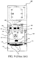
- FIG. 9 is a front view of an air duct structure of a refrigerator 100 disclosed in Japanese Patent Publication No. JP 2009-250476 .
- inlet air doors 105, 106, 107 and 108 are respectively disposed in cool air supply air duct 101, 102, 103 and 104 that send cool air cooled by the cooler to the storage chamber.
- cool air return air ducts 109, 110 and 111 through which the cool air returns from the storage chamber to the cooler are respectively provided with outlet air doors 113, 114 and 115.
- a cool air return air duct (not shown) from a freezing chamber 112 is provided with an outlet air door 116.
- all or part of the inlet air doors 105, 106, 107 and 108 and the outlet air doors 113, 114, 115 and 116 are closed.
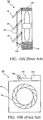
- FIGS. 10A and 10B Another known solution, as shown in FIGS. 10A and 10B , is to dispose forced draft fans 205 and 305 in a cool air blowout port leading to the storage chamber and dispose air volume control mechanisms 200 and 300 on the forced draft fans 205 and 305 (e.g., disclosed in Japanese Patent Publication No. JP 2006-300427 ).
- the air volume control mechanism 200 shown in FIG. 10A includes an air outside frame of the axial forced draft fan 205 mounted to one side of multiple openable and closeable plates 201, to open and close the openable and closeable plates 201 by means of driving of a small motor 204 connected via a connecting plate 202 and a rotating plate 203.
- a suction side of the axial forced draft fan 305 is provided with a wind ring shield 301.
- the wind ring shield 301 is opened and closed by means of a solenoid 304 connected via an operating plate 302 and a connecting shaft 303.
- the air volume control mechanism 200 has great flow resistance. That is, when air flowing on the air outside of the axial forced draft fan forms a rotational flow that takes the vicinity of a fan rotating shaft as a center shaft, the rotational flow will be hindered as the air volume control mechanism 200 is a structure that arranges multiple open and close plates 201 in parallel.
- One of the objectives of the present invention is to provide a shielding device that effectively prevents hot air from flowing into a storage chamber during defrosting and a refrigerator having the shielding device, so as to solve the above-noted problems.
- the present invention provides a shielding device, used for closing a path through which air circulates in a refrigerator.
- the shielding device includes a forced draft fan cover, which has a threaded hole formed with a threaded slot; and a drive shaft, which is formed with a thread screwed with the threaded slot, and extends to pass through the threaded hole, where an air duct that allows the air flows from the inside of the forced draft fan cover to the outside is provided between the drive shaft and the forced draft fan cover.
- a side surface of the thread of the drive shaft is in a tilted shape, and a radial outer side portion of the tilted shape is at a greater distance from the threaded slot of the forced draft fan cover than an inner side portion; and the air duct is formed between the side surface of the thread of the drive shaft and the threaded slot of the forced draft fan cover.
- the shielding device further includes a guide post, which slidably extends to pass through the forced draft fan cover.
- a notch portion is formed by removing one part of the forced draft fan cover which faces the threaded hole; and the notch portion makes up one part of the air duct.
- the shielding device further includes a support portion, which abuts against the notch portion when the forced draft fan cover closes the channel so as to close the air duct.
- the shielding device further includes a thick portion, which is an annular thickened part on the forced draft fan cover which surrounds the threaded hole; wherein an interrupt portion is formed by partially removing the thick portion at the end of the threaded slot.
- the present invention further provides a refrigerator having the shielding device provided in the present invention.
- opening and closing actions of the forced draft fan cover are achieved through a thread mechanism screwed with a drive shaft that extends to pass through the forced draft fan cover.
- an air duct that allows the air flows from the inside of the forced draft fan cover to the outside is provided between the drive shaft and the forced draft fan cover. Accordingly, even if moisture intrudes between the drive shaft and the forced draft fan cover in a use condition, the moisture will be discharged to the outside via the air duct. Thus, that moisture freezes to make the thread mechanism of the shielding device incapable of operating can be prevented.
- the forced draft fan cover of the present invention can move in a manner of leaving a cooling chamber, and thus flow loss of cooling air is very small. Therefore, air that has greater flow velocity in a turning radius direction of the air outside of the forced draft fan can flow into a cooling air duct through the open portion with smaller flow resistance. Therefore, pressure loss of cooling air circulating in the refrigerator can be reduced, and cooling efficiency can be increased.
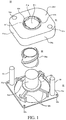
- FIGS. 1, 2A-2C and 3A-3D show the structure of a shielding device 50 according to this exemplary embodiment of the present invention.
- FIG. 1 is a perspective view indicating that components of the shielding device 50 are decomposed along a longitudinal direction.
- FIGS. 2A-22C are diagrams of parts of the shielding device 50.
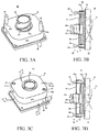
- FIGS. 3A-3D are diagrams of functions of the shielding device 50.
- the shielding device 50 mainly includes a forced draft fan cover 51 substantially cover-shaped, a drive shaft 54 which extends to pass through and drives the forced draft fan cover 51, and a support base 52 used for supporting the forced draft fan cover 51 and the drive shaft 54.
- the main function of the shielding device 50 is inhibiting hot air from leaking to a refrigerating chamber supply air duct 14 during defrosting by closing an open portion of a cooling chamber 13 in a defrosting step.
- the forced draft fan cover 51 is obtained by injection-molding a resin material into a substantially cover shape, which includes a quadrilateral primary surface portion 51d and four side surface portions 51c longitudinally extending from a periphery of the primary surface portion 51d.
- a threaded hole 51c penetrating the vicinity of the center of the primary surface portion 51d and circular is formed.
- a peripheral part of the threaded hole 51c is a thick portion 51h thicker than other parts and ring-like.
- a threaded slot 51f is formed by recessing a side surface of the primary surface portion 51d facing the threaded hole 51c into a helical shape.
- a notch portion 51 g is formed by a sidewall that penetrates the thick portion 51h to partially cut off the threaded hole 51c.
- the forced draft fan cover 51 mainly functions to basically close an air supply outlet 13a of the cooling chamber 13.
- the drive shaft 54 is a cylindrical shape with a lower opening, which is provided with a thread 54a, and the thread 54a is formed by making one part of a side surface of the drive shaft 54 continuously project into a helical shape.
- the thread 54a of the drive shaft 54 is screwed with the threaded slot 51f of the forced draft fan cover 51.
- a shaft support portion 52d of the support base 52 described below is inserted into the inside of the drive shaft 54, and under the action of driving force of a motor built in the shaft support portion 52d, the drive shaft 54 rotates a predetermined angle.
- the drive shaft 54 functions to open and close the forced draft fan cover 51 according to needs through rotation of the drive shaft 54 per se.
- An axial direction of the drive shaft 54 is basically the same as that of the fan 37 ( FIG. 7 ) hereinafter.
- the support base 52 mainly includes a frame portion 52a in a quadrilateral framework when overlooked, a cylindrical shaft support portion 52d disposed in a central portion, a ring-like annular support portion 52c connecting a lower end of the shaft support portion 52d, a support framework 52b connecting the annular support portion 52c and various corners of the frame portion 52a and guide posts 56 vertically disposed near opposite corners of the frame portion 52a.
- the frame portion 52a has a function of mechanically supporting the whole base 52, and its corner is provided with multiple holes 52e. As shown in FIG. 3B , the shielding device 50 including the frame portion 52a can be fixed to a fan shell 36 through, for example, a fixing manner such as passing through the holes 52e with screws.
- the shaft support portion 52d is a cylindrical shape with an opening in a lower portion, which is connected with the frame portion 52a via the support framework 52b.
- the shaft support portion 52d is inserted into the drive shaft 54, and through driving of driving force of the motor built in the shaft support portion 52d, the drive shaft 54 is rotated.
- the annular support portion 52c is a continuous ring-like part integrally formed, which is concentric with the shaft support portion 52d.
- the guide posts 56 are members vertically disposed in positions corresponding to support holes 51b of the forced draft fan cover 51. By inserting each guide post 56 into the support hole 51b, movement of the forced draft fan cover 51 can be guided. As discribed hereinafter with reference to FIG. 2A , in this embodiment, in order to ensure that the air duct has a drainage function, a gap is disposed between the drive shaft 54 and the forced draft fan cover 51. Therefore, only through screwing between the drive shaft 54 and the forced draft fan cover 51, the support base 52 cannot stably support the forced draft fan cover 51. In this embodiment, two guide posts 56 disposed at opposite corners of the support base 52 are slidably inserted into the support holes 51b of the forced draft fan cover 51. In addition, the guide posts 56 are inserted into the support holes 51b seamlessly. Based on the structure, the support base 52 can stably support the forced draft fan cover 51.
- FIG. 2A is a sectional view of a threaded mechanism between the drive shaft 54 and the forced draft fan cover 51
- FIG. 2B is a perspective view of one part of the forced draft fan cover 51
- FIG. 2C is a sectional view of one part of the shielding device 50.
- the threaded mechanism is implemented through screwing between the thread 54a of the drive shaft 54 and the threaded slot 51f of the forced draft fan cover.
- shading and opening of the forced draft fan cover 51 described later are achieved.
- a radial outward direction of a rolling circumference is taken as a +R direction
- a radial inward direction is a -R direction (or called inner side of a rotating direction).
- a side surface 54b of the thread 54a of the drive shaft 54 is set as a tilted surface.
- the thread 54a includes two opposite side surfaces 54b, and two opposite side surfaces 51k are also formed on a threaded slot 51f.
- the side surfaces 54b of the thread 54a are tilted surfaces, which are at a greater distance from the side surfaces of the threaded slot 51f on a +R side than on a -R side (that is, the thread 54a narrows down along the +R direction).
- the side surfaces 51k of the threaded slot 51f are planes parallel to a primary surface of the forced draft fan cover.
- the gap makes the air duct have a function of discharging moisture to the outside. Specifically, in a use condition, even if the moisture enters between the thread 54a and the threaded slot 51f, when air passes through the air duct, water can be discharged to the outside of the shielding device 50. Accordingly, an unfavorable condition that moisture freezing results in that the drive shaft 54 cannot operate can be inhibited.
- the screwing stated hereinabove can be implemented by making the end portion of the -R side of the thread contact an end portion of the -R side of the threaded slot 51f. In this way, by forming a predetermined gap between the drive shaft 54 and the forced draft fan cover 51, screwing between them becomes relaxed.
- the guide posts 56 of the support base 52 are inserted into the support holes 51b of the forced draft fan cover 51, and the forced draft fan cover 51 can be stably placed and supported by the support base 52.
- the thick portion 51h of the forced draft fan cover 51 is provided with an interrupt portion 51i, which locally causes the thick portion 51h to have an interruption (or called discontinuity).
- the interrupt portion 51i is obtained by partially removing a thickened thickness part of the thick portion 51h (formed into a ring shape surrounding the threaded hole 51c).
- the interrupt portion 51i is formed on part of the thick portion 51h of the threaded slot 51f at the end of an upper surface side of the primary surface portion 51d.
- a side surface 51m of the thick portion 51h facing the interrupt portion 51i is a tilted surface, which is tilted to a tangent direction of the threaded hole 51c when overlooked.
- two threaded slots 51f disposed oppositely are formed with an interrupt portion 51i respectively.
- the side surface 51m is a tilted surface, so that an end portion of the thread 54a shown in FIG. 1 and the side surface 51 m of the forced draft fan cover 51 are in point contact, and thus moisture attached to the thread 54a can be well discharged to the outside via the side surface 51 m.
- the side surface 51m faces a radial outer side. In certain embodiments, it may also face an inner side of a rotating direction. Based on the structure, a good drainage effect can be obtained through point contact with the end portion of the thread 54a.
- the structure the same as the thick portion 51h, the interrupt portion 51i and the side surface 51m may also be disposed on an inner side (and a lower surface) of the primary surface portion 51d of the forced draft fan cover 51. Accordingly, the drainage effect stated above will be more significant.
- the interrupt portion 51i is formed by removing all thickened parts of the thick portion.
- the interrupt portion 51i may also be formed by only removing one part of a thickened part of a thick wall. In this case, the interrupt portion 51i becomes a recessed part declined relative to other parts of the thick portion 51h.
- the notch portion 51 g is formed by penetrating the thick portion 51h to partially remove a sidewall of the threaded hole 51c.
- the notch portion 51g is disposed on the opposite thick portion 51h, and keeps away from a part formed with the threaded slot 51f. In this way, by disposing the notch portion 51g penetrating the thick portion, moisture attached to the drive shaft 54 can be discharged to a lower surface side from an upper surface side of the forced draft fan cover 51, so as to inhibit that the moisture freezes to hinder the action of the drive shaft 54.
- an annular support portion 52c is formed. That is, the notch portion 51g and the annular support portion 52c are overlapped when overlooked.
- the drive shaft 54 can be rotated, the forced draft fan cover 51 is declined, and a lower end of the side surface portion 51e of the forced draft fan cover 51 abuts against the frame portion 52a. Accordingly, shutoff of the forced draft fan cover 51 is achieved.
- an upper surface of the annular support portion 52c abuts against a lower end of the thick portion 51h. Accordingly, as internal space of the forced draft fan cover 51 and the outside cannot be connected through the notch portion 51 g, the notch portion 51 g will not affect the shutoff.
- FIG. 3A is a perspective view indicating that the shielding device 50 is in a closed state (shutoff state).
- FIG. 3B is a sectional view indicating that the shielding device 50 is in the closed state.
- FIG. 3C is a perspective view indicating that the shielding device 50 is in an open state.
- FIG. 3D is a sectional view indicating that the shielding device 50 is in the open state.
- the side surface portion 51e of the forced draft fan cover 51 of the shielding device 50 abuts against the support base 52, thus producing an effect of shading them seamlessly.
- conversion from a connection state (open state) of the shielding device 50 to a shaded state can be achieved. That is, in a state that the forced draft fan cover 51 and the support base 52 of the shielding device 50 are separated, the drive shaft 54 is rotated counterclockwise, and in a state that the thread 54a of the drive shaft 54 is screwed with the threaded slot disposed on the threaded hole 51c of the forced draft fan cover 51, the forced draft fan cover 51 moves to the side of the support base 52.
- a gap is formed between them, to become a connection state.
- the forced draft fan cover 51 can be moved towards a direction (Z direction) separated from the support base 52, so as to convert from a shaded state to a connection state. Accordingly, a gap is formed between the side surface portion 51e of the forced draft fan cover 51 and the frame portion 52a of the support base 52, and internal space of the forced draft fan cover 51 is in communication with the outside via the gap.
- air flow can be sent to the outside via the gap formed between the forced draft fan cover 51 and the support base 52.
- FIG. 3C a path through which cool air is supplied between the forced draft fan cover 51 and the support base 52 has been marked with arrows. Accordingly, at the air supply outlet 13a shown in FIG. 7 , the cooling chamber 13 can communicate with the refrigerating chamber supply air duct 14a by releasing shutoff of the shielding device 50, so that cool air can be supplied for the air duct from the cooling chamber 13.
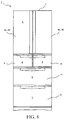
- FIG. 4 a forward external view of a schematic structure of a refrigerator 1 is shown according to one embodiment of the present invention.
- the refrigerator 1 of this embodiment has a heat-insulating cabinet 2 as a body, and a storage chamber that stores food and the like is formed inside the heat-insulating cabinet 2.
- the inside of the storage chamber is partitioned into multiple receiving chambers 3-7 according to different storage temperatures and uses.
- the uppermost layer of the storage chamber is a refrigerating chamber 3.
- An ice-making chamber 4 is on a lower left side of the refrigerating chamber 3, while an upper freezing chamber 5 is on a lower right side of the refrigerating chamber 3.
- a lower layer of the ice-making chamber 4 and the upper freezing chamber 5 is a lower freezing chamber 6.
- the lowest layer of the storage chamber is a vegetable chamber 7.
- the ice-making chamber 4, the upper freezing chamber 5 and the lower freezing chamber 6 are receiving chambers whose temperatures are within a range of freezing temperatures, which, in later description, are collectively called an ice-making chamber.
- a front side opening of the heat-insulating cabinet 2 and openings corresponding to the receiving chambers 3-7 are respectively provided with heat-insulating doors 8-12 that can be opened and closed.
- the heat-insulating doors 8a and 8b separately cover the front side of the refrigerating chamber 3, and left upper and lower portions of the heat-insulating door 8a and right left upper and lower portions of the heat-insulating door 8b are rotatably supported to the heat-insulating cabinet 2.
- the heat-insulating doors 9-12 are respectively combined with corresponding receiving containers into a whole, so as to be capable of being supported to the heat-insulating cabinet 2 in a pull-out manner in front of the refrigerator 1.
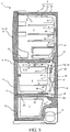
- FIG. 5 is a side sectional view of a schematic structure of the refrigerator 1.
- the heat-insulating cabinet 2 as the body of the refrigerator 1 includes a steel plate housing 2a opened at a front side, a synthetic resin liner 2b disposed in the housing 2a with a gap and opened at a front side, and a foaming polyurethane heat-insulating material 2c formed by filling and foaming in a gap between the housing 2a and the liner 2b.
- the heat-insulating doors 8-12 may also adopt a heat-insulating structure the same as the heat-insulating cabinet 2.
- the refrigerating chamber 3 is separated from the ice-making chambers 4-6 located therebelow by heat-insulating partition walls 28.
- the ice-making chamber 4 and the upper freezing chamber 5 inside the ice-making chambers 4-6 are separated by partition walls (not shown).
- the ice-making chamber 4 and the upper freezing chamber 5 are in communication with the lower freezing chamber 6 disposed below them, and cool air can circulate therebetween.
- the ice-making chambers 4-6 and the vegetable chamber 7 are separated by heat-insulating partition walls 29.
- a rear side of the refrigerating chamber 3 is formed with a refrigerating chamber supply air duct 14 formed by separation of a synthetic resin partition body 45 and serving as a supply air duct that supplies cool air for the refrigerating chamber 3.
- the refrigerating chamber supply air duct 14 is formed with a blowout port 17 that allows the cool air to flow into the refrigerating chamber 3.
- the refrigerating chamber supply air duct 14 is provided thereon with a refrigerating chamber air door 25.
- the refrigerating chamber air door 25 is an air door that can be opened and closed under the driving of a motor and the like, used for controlling the flow rate of the cool air supplied to the refrigerating chamber 3, so as to keep the inside of the refrigerating chamber 3 at an appropriate temperature.
- Rear sides of the ice-making chambers 4-6 are formed with a freezing chamber supply air duct 15, used for allowing the cool air cooled by the refrigerating chamber 3 to flow to the ice-making chambers 4-6.
- a more rear side of the freezing chamber supply air duct 15 is formed with a cooling chamber 13, inside which is provided with a cooler 32 (evaporator) used for cooling circulating air in the refrigerator.
- the cooler 32 is connected with a compressor 31, a radiator (not shown) and an expansion valve (capillary tube, not shown) via a refrigerant piping, to make up a vapor-compression refrigeration circulation loop.
- iso-butane (R600a) is used as a refrigerant of the refrigeration circulation.
- the refrigerator 1 includes a refrigerating chamber temperature sensor 55 used for detecting an inside temperature of the refrigerating chamber 3, a freezing chamber temperature sensor 53 used for detecting inside temperature of the ice-making chambers 4-6 and other various sensors not shown.
- the refrigerator 1 includes a control device not shown, and the control device executes specified algorithm processing based on input values of the sensors, to control the compressor 31, the forced draft fan 35, the shielding device 50, the refrigerating chamber air door 25 and other components.
- FIG. 6 is a forward schematic view of a schematic structure of a supply air duct of the refrigerator 1.
- the refrigerating chamber supply air duct 14 transports the cool air to the uppermost portion at the central portion of the refrigerating chamber 3, and then makes the cool air decline from two sides, to supply the cool air into the refrigerating chamber 3. Accordingly, the cool air can be effectively supplied to the whole inside of the refrigerating chamber 3.
- the refrigerator 1 includes a return air duct 20 that makes the air flow back to the cooling chamber 13 from the refrigerating chamber 3.
- a lower portion of the refrigerating chamber 3 is formed with a return air inlet 22, and the return air inlet 22 is an opening through which the refrigerating chamber 3 leads to the return air duct 20.
- the air in the refrigerating chamber 3 flows to the return air duct 20 via the return air inlet 22, and flows to the lower side of the cooler 32.
- the front of the return air duct 20 is formed with a vegetable chamber supply air duct 16 that allows the air cooled by the cooler 32 to flow to the vegetable chamber 7.
- the vegetable chamber supply air duct 16 forks from the freezing chamber supply air duct 15 towards the upper side, and after extending to pass through the inside of the heat-insulating partition walls 28 (referring to FIG. 5 ) above the ice-making chambers 4-6, changes to extend downwards from the rear sides of the ice-making chambers 4-6. Then, it passes through the heat-insulating partition wall 29 (referring to FIG. 5 ) to communicate to the vegetable chamber 7.
- the vegetable chamber 7 is formed with a blowout port 19, and the blowout port 19 is an opening that supplies the cool air from the vegetable chamber supply air duct 16 to the vegetable chamber 7.
- the vegetable chamber supply air duct 16 is provided with a vegetable chamber air door 26, used for controlling the flow rate of the cool air supplied to the vegetable chamber 7. Accordingly, the vegetable chamber 7 can be cooled independent of cooling of the refrigerating chamber 3, so as to properly control the temperature of the vegetable chamber 7.
- the vegetable chamber supply air duct 16 can be shortened, to reduce pressure loss.
- the vegetable chamber supply air duct 16 can be constructed to fork from the return air duct 20, and the cost can be reduced by omitting the vegetable chamber air door 26.
- a return air inlet 24 is formed on the vegetable chamber 7, and the air in the vegetable chamber 7 flows towards the lower portion of the cooling chamber 13 via a return air duct 21 and a return air inlet 13b of the vegetable chamber.
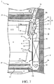
- FIG. 7 is a side sectional view of a structure near the cooling chamber 13 of the refrigerator 1.
- the cooling chamber 13 is disposed in a rear side of the freezing chamber supply air duct 15 inside the heat-insulating cabinet 2.
- the cooling chamber 13 is separated from the freezing chamber supply air duct 15 or the synthetic resin partition body 46 between the ice-making chambers 4-6. That is, the cooling chamber 13 is space sandwiched by the liner 2b and the partition body 46.
- the freezing chamber supply air duct 15 formed in the front of the cooling chamber 13 is space formed between the partition body 46 and a synthetic resin front cover 47 assembled to the front thereof, used as an air duct where the cool air cooled by the cooler 32 flows.
- a blowout port 18 is formed on the front cover 47, used as an opening that blows out cool air to the ice-making chambers 4-6.
- the back of the lower portion of the lower refrigerating chamber 6 is formed with a return air inlet 23 that allows air to return to the cooling chamber 13 from the ice-making chambers 4-6.
- a return air inlet 13b is formed below the cooling chamber 13, which is connected with the return air inlet 23, and sucks return cool air from the storage chamber into the inside of the cooling chamber 13.
- a defrost heater 33 is disposed below the cooler 32, used as a defrost device that melts and removes frost attached to the cooler 32.
- the defrost heater 33 is a resistance-heated heater.
- An air supply outlet 13a is formed on the partition body 46 in the upper portion of the cooling chamber 13, used as an opening connected with the refrigerating chambers 3-7. That is, the air supply outlet 13a is an opening that allows the cool air cooled by the cooler 32 to flow, and connects the cooling chamber 13, the refrigerating chamber supply air duct 14, the freezing chamber supply air duct 15 and the vegetable chamber supply air duct 16 (referring to FIGS. 3A-3D ).
- the air supply outlet 13a is provided with a forced draft fan 35 that transports cool air to the ice-making chambers 4-6.
- the forced draft fan 35 is an axial forced draft fan, and has a rotary fan 37 (propeller fan) and a fan shell 36, and the fan shell 36 is formed with a wind tunnel 36a substantially opened cylindrically.
- the fan shell 36 is mounted to the air supply outlet 13a of the cooling chamber 13, and is a member that becomes a border between the suction side and the air outside of the forced draft fan 35.
- a fan 37 is provided coaxially with the wind tunnel 36a on the fan shell 36.
- the end portion of the air outside of the fan 37 is disposed as much closer to the outer side than the end portion of the air outside of the wind tunnel 36a, that is, than the end face of the air outside of the fan shell 36, i.e., much closer to the air outside or the side of the freezing chamber supply air duct 15. Accordingly, flow resistance of exhaust air flowing along a turning radius direction of the fan 37 becomes small, and cool air can be sent out with smaller flow loss.
- an outer side of the air supply outlet 13a of the cooling chamber 13, i.e., an air outside of the forced draft fan 35, is provided with a shielding device 50, and the shielding device 50 is used for closing a forced draft fan cover 51 of the air supply outlet 13a.
- the shielding device 50 is mounted to make the support base 52 to closely contact, for example, with the fan shell 36 of the forced draft fan 35.
- the forced draft fan cover 51 is substantially cover-shaped. Accordingly, the forced draft fan cover 51 may not contact the fan 37 more projecting towards the air outside than the fan shell 36, and can abut against the support base 52 on the outer side of the wind tunnel 36a, so as to close the air supply outlet 13a.
- FIGS. 8A-8C are illustrative schematic views of analysis results of air flow under different conditions around the axial forced draft fan serving as the forced draft fan 35, wherein FIG. 8A is an analysis result when a pressure difference of the out-air side and the suction side is 12 Pa, FIG. 8B is an analysis result when the pressure difference is 4 Pa, and FIG. 8C is an analysis result when the pressure difference is 2 Pa.
- a sign V is wind velocity vector distribution on a surface (referring to FIG. 6 ) of the frame portion 52a of the support base 52.
- the sign V is equivalent to wind velocity vector distribution on the air outside end face of the fan shell 36.
- a sign V1 indicates wind velocity vector distribution on a surface S1 at the suction side (right side of the paper)
- a sign V2 indicates wind velocity vector distribution on a surface S2 at the air outside (left side of the paper).
- the wind velocity vectors V, V1 and V2 are represented as: arrow directions are taken as directions of the air flow, and the arrow length is in proportion to the velocity of the air flow.
- transverse lines M drawn above and below the fan 37 are lines used to facilitate calculation, but are not used to describe analysis results, and the transverse lines M can be ignored.
- the wind velocity vector V of the out-air side of the forced draft fan 35 changes to be basically towards the up-down direction of the figure.
- the wind velocity vector V2 on the surface S2 of the air outside becomes very short. It can be seen that in the condition that the pressure difference is 12 Pa, the speed of the air flow blown out by the forced draft fan 35 in the rotary shaft direction Z of the fan 37 becomes very small, and the speed in the turning radius direction R becomes large. In other words, the air flow blown out by the forced draft fan 35 will not flow to the front (i.e., Z direction) of the forced draft fan 35, but flows to the turning radius direction R.
- the above describes the characteristics of the axial forced draft fan that serves as the forced draft fan 35, and according to the illustration of the refrigerator 1 of this embodiment, in the refrigerator where cool air is forced to circulate in a closed loop, the pressure difference of the out-air side and the suction side of the forced draft fan 35 is about 10-12 Pa. That is to say, as shown in FIG. 8A , the cool air blown out by the forced draft fan 35 will expand and flow towards the turning radius direction R of the fan 37 of the forced draft fan 35.
- the forced draft fan cover 51 moves in a manner of leaving the cooling chamber 13 when cooling the ice-making chambers 4-6, and an opening used for flowing of the cool air will be formed between the forced draft fan cover 51 and the cooling chamber 13.
- the air at a greater flow velocity in the turning radius R blown out by the forced draft fan 35 will, along the fan shell 36 and the partition body 46 through the opening, flow into the freezing chamber supply air duct 15 (and the refrigerating chamber supply air duct 14) with very small flow resistance.
- a distance X (i.e., the distance X forming an air flow path opening) between the primary surface of the support base 52 and the side end face of the forced draft fan 35 of the forced draft fan cover 51 has a particular length.
- the distance X should be ensured to be more than 30 mm and preferably more than 50 mm. If the distance X is shorter than 30 mm, flow loss caused by the forced draft fan cover 51 will increase, and compared with the situation where the prior art uses air doors and the like, it is difficult to inhibit the pressure loss to be less.
- a surface S3 of the air outside shown in the figure is in a position where the distance X (referring to FIG. 3C ) is equal to 50 mm.
- the surface S2 is in a position where the distance X is equal to 80 mm. It can be known from the figure that, as long as the position from the opening to the surface S3 is ensured, i.e., to the position where the distance X is equal to 50 mm, the air flow is hardly hindered when passing through the opening.
- the compressor 31 operates, the refrigerating chamber air door 25 is opened, to make the forced draft fan 35 operate, and thus the refrigerating chamber 3 is cooled. That is, air cooled by the cooler 32 sequentially passes through the air supply outlet 13a (forced draft fan 35) of the cooling chamber 13, the refrigerating chamber air door 25, the refrigerating chamber supply air duct 14 and the blowout port 17, to be supplied to the refrigerating chamber 3. Accordingly, food and the like stored in the refrigerating chamber 3 can be cooled and stored at an appropriate temperature.
- the shielding device 50 becomes an open state, and the cooling chamber 13 and the refrigerating chamber supply air duct 14a become a connection state. That is, the shielding device 50, as shown in FIG. 3C , is separated from the forced draft fan cover 51 and the support base 52, and the cooled air is supplied to the refrigerating chamber 3 from a gap therebetween.
- the compressor 31 operates, the forced draft fan 35 operates, the forced draft fan cover 51 is opened, and thus the ice-making chambers 4-6 can be cooled.
- the forced draft fan cover 51 is in a state of leaving the support base 52 as shown in FIG. 3C . Accordingly, air cooled by the cooler 32 is sent out via the forced draft fan 35 disposed at the air supply outlet 13a of the cooling chamber 13, sequentially passes through the freezing chamber supply air duct 15 and the blowout port 18, and is supplied to the ice-making chambers 4-6.
- cool air supply for the vegetable chamber 7 is described.
- one part of the air sent to the freezing chamber supply air duct 15 by using the forced draft fan 35 flows to the vegetable chamber supply air duct 16 as shown in FIG. 6 , and then is blown to the vegetable chamber 7 from the blowout port 9. Accordingly, the inside of the vegetable chamber 7 can be cooled.
- the cool air circulating in the vegetable chamber 7 sequentially passes through the vegetable chamber return air duct 21 and the return air inlet 13b from the return air inlet shown in FIG. 6 to return to the cooling chamber 13.
- cool air cooled by one cooler 32 can be efficiently supplied to the refrigerating chambers 3-7 separately with less pressure loss. Accordingly, the refrigerating chamber 3 and the ice-making chambers 4-6 can be properly cooled respectively according to respective cooling load.
- the refrigerating chamber 3 can be enlarged.
- a cooling temperature (refrigerant evaporating temperature) of the cooler 32 can be adjusted according to a target cold-keeping temperature of the storage chamber for which cool air should be supplied, which can thus further increase efficiency of refrigeration cycle.
- frost will be attached to an air side heat-transfer surface of the cooler 32, which hinders heat transfer and will block an air flow path. Therefore, after frosting is judged from reduction of the refrigerant evaporating temperature or the like or frosting is judged by a defrost timer or the like, a defrosting and cooling operation or a defrosting operation begins, to remove the frost attached to the cooler 32.
- the defrosting and cooling operation of cooling the refrigerating chamber 3 by using latent heat of the frost attached to the cooler 32.
- the compressor 31 stops operating, to form a state where the forced draft fan cover 51 is opened as shown in FIG. 3C .
- the refrigerating chamber air duct 25 is opened, to make the forced draft fan 35 operate.
- air can circulate between the refrigerating chamber 3 and the cooling chamber 13, and the frost attached to the cooler 32 is melted by using the circulating air. That is, defrosting can be performed without heating of the defrost heater 33. Meanwhile, the refrigerating chamber 3 can be cooled without letting the compressor 31 operate, but by using heat of melting of the frost.
- heater input used for defrosting and compressor input used for cooling can be reduced, to reduce power consumption of the refrigerator 1, and comprehensively increase cooling efficiency.
- food and the like stored therein can be prevented from drying, to increase fresh-keeping effects.
- a supply air duct that supplies cool air to the vegetable chamber 7 without through the freezing chamber supply air duct 15 cooling by using latent heat of the defrosting and moisture replenishing can be performed thereon even for the vegetable chamber 7.
- the shielding device 50 of this embodiment has many structures used for discharging the attached moisture, and a situation where the action of the drive shaft 54 is hindered due to the moisture will not occur. That is, referring to FIGS. 1 and 2A-2C , even if moisture enters between the forced draft fan cover 51 and the drive shaft 54, as it is ensured that an air duct exists between them, good drainage can be achieved by letting the air pass through the air duct.
- the defrosting and cooling operation is performed in a situation where it is judged that the cooler 32 defrosts and the temperature of the refrigerating chamber 3 is higher than a predetermined threshold. Even if it is detected that the cooler 32 defrosts, when the temperature of the refrigerating chamber 3 is lower than the predetermined threshold, it is unnecessary to cool the refrigerating chamber 3, and thus the defrosting and cooling operation may not be performed, but the conventional defrosting operation is performed by using the defrost heater 33.
- the conventional defrosting operation is described below.
- the compressor 31 stops, and the defrost heater 33 is powered on, so as to melt the frost attached to the cooler 32.
- the air supply outlet 13a is closed and the refrigerating chamber air door 25 is closed by using the forced draft fan cover 51. That is, through rotation of the drive shaft 54, the shielding device 50 can be changed into the shaded state shown in FIG. 3A . Accordingly, air in the cooling chamber 13 heated by the defrost heater 33 can be prevented from flowing into the refrigerating chamber supply air duct 14 and the like. As a result, cooling efficiency of the refrigerator 1 can be increased.
- an opening-adjustable wing plate (not shown) at the blowout port 17 on the front portion of the upper surface of the refrigerating chamber 3.
- a suitable air curtain used for preventing cool air from leaking to the outside from the inside of the refrigerating chamber 3 is formed.
- the forced draft fan 35 can continuously operate after a period of predetermined time after the heat-insulating door 8 is closed, and the wing plate can also swing. Accordingly, the inside of the refrigerating chamber 3 becoming warmer due to opening of the heat-insulating door 8 can be effectively cooled, especially a receiving wall box 57 on an inner side of the heat-insulating door 8.
- the refrigerator 1 during defrosting, can use the forced draft fan cover 51 to close the air supply outlet 13a of the cooling chamber 13, and thus hot air during defrosting can be prevented from flowing into the storage chamber.
- the forced draft fan cover 51 is mounted to an outer side of the air supply outlet 13a of the cooling chamber 13, that is, an air outside of the forced draft fan 35, and thus it is universal even if for other models of refrigerators with air ducts in different shapes.
- the forced draft fan cover 51 and the forced draft fan 35 form a structural member integrally assembled for use. Accordingly, no matter which air duct structure it is, leakage of defrosting hot air can be prevented, and thus design freedom of the cooling air duct can be increased, and air duct design can be done easily. Therefore, development cost and product cost of the cooling air duct and the air door can be reduced.
Landscapes
- Engineering & Computer Science (AREA)
- Chemical & Material Sciences (AREA)
- Combustion & Propulsion (AREA)
- Physics & Mathematics (AREA)
- Mechanical Engineering (AREA)
- Thermal Sciences (AREA)
- General Engineering & Computer Science (AREA)
- Cold Air Circulating Systems And Constructional Details In Refrigerators (AREA)
Abstract
Description
- The present invention relates generally to a refrigerator, and more particularly, to a shielding device that blocks an air duct where cool air circulates in a refrigerator according to needs and a refrigerator having the shielding device.
- In a conventional refrigerator, when a cooler is defrosted, there is a problem that hot air surrounding the cooler heated by a defrost heater flows into a storage chamber to raise the temperature in the storage chamber. Therefore, to prevent hot air in a defrosting operation from entering into the storage chamber, a known solution is to dispose an air door in a cooling air duct and close the air door in the defrosting operation (e.g., disclosed in Japanese Patent Publication No.
JP 2009-250476 -
FIG. 9 is a front view of an air duct structure of arefrigerator 100 disclosed in Japanese Patent Publication No.JP 2009-250476 refrigerator 100,inlet air doors supply air duct return air ducts outlet air doors freezing chamber 112 is provided with anoutlet air door 116. Moreover, in the defrosting operation, all or part of theinlet air doors outlet air doors - Another known solution, as shown in
FIGS. 10A and 10B , is to dispose forceddraft fans volume control mechanisms draft fans 205 and 305 (e.g., disclosed in Japanese Patent Publication No.JP 2006-300427 - The air
volume control mechanism 200 shown inFIG. 10A includes an air outside frame of the axial forceddraft fan 205 mounted to one side of multiple openable andcloseable plates 201, to open and close the openable andcloseable plates 201 by means of driving of asmall motor 204 connected via aconnecting plate 202 and arotating plate 203. - In addition, in the air
volume control mechanism 300 shown inFIG. 10B , a suction side of the axial forceddraft fan 305 is provided with awind ring shield 301. Thewind ring shield 301 is opened and closed by means of asolenoid 304 connected via anoperating plate 302 and aconnecting shaft 303. - However, as shown in
FIG. 9 , in the prior art refrigerators which dispose air doors in cooling air ducts, for various refrigerators designed to have different capacity and functions, it is necessary to design respective air ducts and air doors corresponding to the air ducts for each model. Therefore, if air doors adapted to various models of air ducts are disposed, the kinds of the air doors will increase, to become a multi-specification & small batch production manner, and there is a problem that development cost and production cost of the air doors increase. - In addition, as shown in
FIG. 10A , in the structure that the airvolume control mechanism 200 is mounted to the forceddraft fan 205, there is a problem that the airvolume control mechanism 200 has great flow resistance. That is, when air flowing on the air outside of the axial forced draft fan forms a rotational flow that takes the vicinity of a fan rotating shaft as a center shaft, the rotational flow will be hindered as the airvolume control mechanism 200 is a structure that arranges multiple open andclose plates 201 in parallel. - In addition, when the
wind ring shield 301 shown inFIG. 10B is used at the air outside of the forced draft fan, there is a problem that an air-out portion of the forced draft fan has great pressure loss. That is, when air flowing on the air outside of the forced draft fan in the refrigerator has a characteristic that flow velocity in a turning radius direction is greater than that in a fan rotating shaft direction, thewind ring shield 301 will hinder flowing in the turning radius direction. - Moreover, in use of the structure of the openable and
closeable plates 201 shown inFIG. 10A and the structure of thewind ring shield 301 shown inFIG. 10B , it is likely that attached moisture freezes to hinder actions thereof. - One of the objectives of the present invention is to provide a shielding device that effectively prevents hot air from flowing into a storage chamber during defrosting and a refrigerator having the shielding device, so as to solve the above-noted problems.
- In one aspect, the present invention provides a shielding device, used for closing a path through which air circulates in a refrigerator. The shielding device includes a forced draft fan cover, which has a threaded hole formed with a threaded slot; and a drive shaft, which is formed with a thread screwed with the threaded slot, and extends to pass through the threaded hole, where an air duct that allows the air flows from the inside of the forced draft fan cover to the outside is provided between the drive shaft and the forced draft fan cover.
- In one embodiment, a side surface of the thread of the drive shaft is in a tilted shape, and a radial outer side portion of the tilted shape is at a greater distance from the threaded slot of the forced draft fan cover than an inner side portion; and the air duct is formed between the side surface of the thread of the drive shaft and the threaded slot of the forced draft fan cover.
- In one embodiment, the shielding device further includes a guide post, which slidably extends to pass through the forced draft fan cover.
- In one embodiment, a notch portion is formed by removing one part of the forced draft fan cover which faces the threaded hole; and the notch portion makes up one part of the air duct.
- In one embodiment, the shielding device further includes a support portion, which abuts against the notch portion when the forced draft fan cover closes the channel so as to close the air duct.
- In one embodiment, the shielding device further includes a thick portion, which is an annular thickened part on the forced draft fan cover which surrounds the threaded hole; wherein an interrupt portion is formed by partially removing the thick portion at the end of the threaded slot.
- In another aspect, the present invention further provides a refrigerator having the shielding device provided in the present invention.
- According to the present invention, opening and closing actions of the forced draft fan cover are achieved through a thread mechanism screwed with a drive shaft that extends to pass through the forced draft fan cover. Moreover, an air duct that allows the air flows from the inside of the forced draft fan cover to the outside is provided between the drive shaft and the forced draft fan cover. Accordingly, even if moisture intrudes between the drive shaft and the forced draft fan cover in a use condition, the moisture will be discharged to the outside via the air duct. Thus, that moisture freezes to make the thread mechanism of the shielding device incapable of operating can be prevented.
- In addition, setting a side surface of the thread of the drive shaft in a tilted shape can ensure that there is a greater gap between it and the threaded slot of the forced draft fan cover. Therefore, an effect of discharging moisture is increased.
- Further, cutting a notch from one part of the forced draft fan cover ensures the air duct. Thus, a drainage effect is also increased.
- Moreover, the forced draft fan cover of the present invention can move in a manner of leaving a cooling chamber, and thus flow loss of cooling air is very small. Therefore, air that has greater flow velocity in a turning radius direction of the air outside of the forced draft fan can flow into a cooling air duct through the open portion with smaller flow resistance. Therefore, pressure loss of cooling air circulating in the refrigerator can be reduced, and cooling efficiency can be increased.
-
-
FIG. 1 is an exploded perspective view of a shielding device according to one embodiment of the present invention. -
FIGS. 2A-2C are views of a shielding device according to one embodiment of the present invention, whereinFIG. 2A is a sectional view of a related structure of a threaded slot and a thread,FIG. 2B is a perspective view of one part of a forced draft fan cover, andFIG. 2C is a sectional view of one part of the shielding device. -
FIGS. 3A-D are views of a shielding device according to one embodiment of the present invention, whereinFIG. 3A is a perspective view indicating that the shielding device is in a shaded state,FIG. 3B is a sectional view indicating that the shielding device is in the shaded state,FIG. 3C is a perspective view indicating that the shielding device is in a connection state, andFIG. 3D is a sectional view indicating that the shielding device is in the connection state. -
FIG. 4 is a forward external view of a refrigerator according to one embodiment of the present invention; -
FIG. 5 is a side sectional view of a schematic structure of a refrigerator according to one embodiment of the present invention. -
FIG. 6 is a forward schematic view of a supply air duct of a refrigerator according to one embodiment of the present invention. -
FIG. 7 is a side sectional view of a structure near a cooling chamber of a refrigerator according to one embodiment of the present invention. -
FIGS. 8A-8C are illustrative schematic views of air flow analysis results surrounding an axial forced draft fan under different conditions, whereinFIG. 8A a pressure difference of an air outside and a suction side is 12 Pa,FIG. 8B the pressure difference of the air outside and the suction side is 4 Pa, andFIG. 8C the pressure difference of the air outside and the suction side is 2 Pa. -
FIG. 9 is a front view of one example of a prior art refrigerator. -
FIGS. 10A-10B are views of an air volume control mechanism of another prior art refrigerator, whereinFIG. 10A is a sectional view, andFIG. 10B is a front view. - Numeral references in the figures respectively refer to the following elements:
1 - refrigerator 2 - heat-insulating cabinet 2a - housing 2b - liner 2c - heat-insulating material 3 - refrigerating chamber 4 - ice-making chamber 5 - upper freezing chamber 6 - lower freezing chamber 7 - vegetable chamber 8, 8a, 8b - heat-insulating doors 9- heat-insulating doors 10 - heat-insulating doors 11 - heat-insulating doors 12 - heat-insulating doors 13 - cooling chamber 13a - air supply outlet 13b - return air inlet 14 - refrigerating chamber supply air duct 14a - refrigerating chamber supply air duct 15 - freezing chamber supply air duct 16 - vegetable chamber supply air duct 17 - blowout port 18 - blowout port 19 - blowout port 20 - return air duct 21 - vegetable chamber return air duct 22 - return air inlet 23 - return air inlet 24 - return air inlet 25 - refrigerating chamber air duct 26 - vegetable chamber air door 28 - heat-insulating partition walls 29 - heat-insulating partition walls 31 - compressor 32 - cooler 33 - defrost heater 35 - forced draft fan 36 - fan shell 36a - wind tunnel 37 - rotary fan 45 - partition body 46 - partition body 47 - front cover 50 - shielding device 51 - forced draft fan cover 51b - support holes 51c - threaded hole 51d - primary surface portion 51e - side surface portion 51f - threaded slot 51g - notch portion 51h - thick portion 51i - interrupt portion 51k - side surfaces 51m - side surface 52 - support base 52a - frame portion 52b - support framework 52c - annular support portion 52d - shaft support portion 52e - holes 53 - freezing chamber temperature sensor 54 - drive shaft 54a - thread 54b - side surface 55 - refrigerating chamber temperature sensor 56 - guide posts -
FIGS. 1, 2A-2C and 3A-3D show the structure of ashielding device 50 according to this exemplary embodiment of the present invention.FIG. 1 is a perspective view indicating that components of theshielding device 50 are decomposed along a longitudinal direction.FIGS. 2A-22C are diagrams of parts of theshielding device 50.FIGS. 3A-3D are diagrams of functions of theshielding device 50. - Referring to
FIG. 1 , the shieldingdevice 50 mainly includes a forceddraft fan cover 51 substantially cover-shaped, adrive shaft 54 which extends to pass through and drives the forceddraft fan cover 51, and asupport base 52 used for supporting the forceddraft fan cover 51 and thedrive shaft 54. Referring toFIG. 7 , the main function of theshielding device 50 is inhibiting hot air from leaking to a refrigerating chambersupply air duct 14 during defrosting by closing an open portion of a coolingchamber 13 in a defrosting step. - In certain embodiments, the forced
draft fan cover 51 is obtained by injection-molding a resin material into a substantially cover shape, which includes a quadrilateralprimary surface portion 51d and fourside surface portions 51c longitudinally extending from a periphery of theprimary surface portion 51d. In addition, a threadedhole 51c penetrating the vicinity of the center of theprimary surface portion 51d and circular is formed. A peripheral part of the threadedhole 51c is athick portion 51h thicker than other parts and ring-like. A threadedslot 51f is formed by recessing a side surface of theprimary surface portion 51d facing the threadedhole 51c into a helical shape. In addition, anotch portion 51 g is formed by a sidewall that penetrates thethick portion 51h to partially cut off the threadedhole 51c. As described later with reference toFIG. 7 , the forceddraft fan cover 51 mainly functions to basically close anair supply outlet 13a of the coolingchamber 13. - The
drive shaft 54 is a cylindrical shape with a lower opening, which is provided with athread 54a, and thethread 54a is formed by making one part of a side surface of thedrive shaft 54 continuously project into a helical shape. In use, thethread 54a of thedrive shaft 54 is screwed with the threadedslot 51f of the forceddraft fan cover 51. In addition, ashaft support portion 52d of thesupport base 52 described below is inserted into the inside of thedrive shaft 54, and under the action of driving force of a motor built in theshaft support portion 52d, thedrive shaft 54 rotates a predetermined angle. Thedrive shaft 54 functions to open and close the forceddraft fan cover 51 according to needs through rotation of thedrive shaft 54 per se. An axial direction of thedrive shaft 54 is basically the same as that of the fan 37 (FIG. 7 ) hereinafter. - The
support base 52 mainly includes aframe portion 52a in a quadrilateral framework when overlooked, a cylindricalshaft support portion 52d disposed in a central portion, a ring-likeannular support portion 52c connecting a lower end of theshaft support portion 52d, asupport framework 52b connecting theannular support portion 52c and various corners of theframe portion 52a and guideposts 56 vertically disposed near opposite corners of theframe portion 52a. - The
frame portion 52a has a function of mechanically supporting thewhole base 52, and its corner is provided withmultiple holes 52e. As shown inFIG. 3B , the shieldingdevice 50 including theframe portion 52a can be fixed to afan shell 36 through, for example, a fixing manner such as passing through theholes 52e with screws. - The
shaft support portion 52d is a cylindrical shape with an opening in a lower portion, which is connected with theframe portion 52a via thesupport framework 52b. Theshaft support portion 52d is inserted into thedrive shaft 54, and through driving of driving force of the motor built in theshaft support portion 52d, thedrive shaft 54 is rotated. - The
annular support portion 52c is a continuous ring-like part integrally formed, which is concentric with theshaft support portion 52d. When the forceddraft fan cover 51 is closed in a use condition, thenotch portion 51 g of the forced draft fan cover is covered by theannular support portion 52c of thesupport base 52. Accordingly, hot air can be prevented from leaking via the notch portion 50g. - The guide posts 56 are members vertically disposed in positions corresponding to support
holes 51b of the forceddraft fan cover 51. By inserting each guide post 56 into thesupport hole 51b, movement of the forceddraft fan cover 51 can be guided. As discribed hereinafter with reference toFIG. 2A , in this embodiment, in order to ensure that the air duct has a drainage function, a gap is disposed between thedrive shaft 54 and the forceddraft fan cover 51. Therefore, only through screwing between thedrive shaft 54 and the forceddraft fan cover 51, thesupport base 52 cannot stably support the forceddraft fan cover 51. In this embodiment, twoguide posts 56 disposed at opposite corners of thesupport base 52 are slidably inserted into the support holes 51b of the forceddraft fan cover 51. In addition, the guide posts 56 are inserted into the support holes 51b seamlessly. Based on the structure, thesupport base 52 can stably support the forceddraft fan cover 51. - The shielding
device 50 will be further described below in detail with reference toFIGS. 2A-2C. FIG. 2A is a sectional view of a threaded mechanism between thedrive shaft 54 and the forceddraft fan cover 51,FIG. 2B is a perspective view of one part of the forceddraft fan cover 51, andFIG. 2C is a sectional view of one part of theshielding device 50. - Referring to
FIG. 2A , as described above, the threaded mechanism is implemented through screwing between thethread 54a of thedrive shaft 54 and the threadedslot 51f of the forced draft fan cover. Through rotation of thedrive shaft 54, shading and opening of the forceddraft fan cover 51 described later are achieved. As an example, a radial outward direction of a rolling circumference is taken as a +R direction, and a radial inward direction is a -R direction (or called inner side of a rotating direction). - In this embodiment, a
side surface 54b of thethread 54a of thedrive shaft 54 is set as a tilted surface. Specifically, thethread 54a includes two opposite side surfaces 54b, and two opposite side surfaces 51k are also formed on a threadedslot 51f. The side surfaces 54b of thethread 54a are tilted surfaces, which are at a greater distance from the side surfaces of the threadedslot 51f on a +R side than on a -R side (that is, thethread 54a narrows down along the +R direction). On the other hand, the side surfaces 51k of the threadedslot 51f are planes parallel to a primary surface of the forced draft fan cover. Moreover, there is a distance between an end portion of the +R side of thethread 54a and a sidewall of the threadedslot 51f. Accordingly, even if thedrive shaft 54 is screwed to the forceddraft fan cover 51, it can still ensure that there is a sufficient gap between thethread 54a and the threadedslot 51f. - The gap makes the air duct have a function of discharging moisture to the outside. Specifically, in a use condition, even if the moisture enters between the
thread 54a and the threadedslot 51f, when air passes through the air duct, water can be discharged to the outside of theshielding device 50. Accordingly, an unfavorable condition that moisture freezing results in that thedrive shaft 54 cannot operate can be inhibited. In addition, the screwing stated hereinabove can be implemented by making the end portion of the -R side of the thread contact an end portion of the -R side of the threadedslot 51f. In this way, by forming a predetermined gap between thedrive shaft 54 and the forceddraft fan cover 51, screwing between them becomes relaxed. However, as described above with reference toFIG. 1 , the guide posts 56 of thesupport base 52 are inserted into the support holes 51b of the forceddraft fan cover 51, and the forceddraft fan cover 51 can be stably placed and supported by thesupport base 52. - Referring to
FIG. 2B , thethick portion 51h of the forceddraft fan cover 51 is provided with an interruptportion 51i, which locally causes thethick portion 51h to have an interruption (or called discontinuity). The interruptportion 51i is obtained by partially removing a thickened thickness part of thethick portion 51h (formed into a ring shape surrounding the threadedhole 51c). In addition, the interruptportion 51i is formed on part of thethick portion 51h of the threadedslot 51f at the end of an upper surface side of theprimary surface portion 51d. Moreover, aside surface 51m of thethick portion 51h facing the interruptportion 51i is a tilted surface, which is tilted to a tangent direction of the threadedhole 51c when overlooked. In this embodiment, two threadedslots 51f disposed oppositely are formed with an interruptportion 51i respectively. - The
side surface 51m is a tilted surface, so that an end portion of thethread 54a shown inFIG. 1 and theside surface 51 m of the forceddraft fan cover 51 are in point contact, and thus moisture attached to thethread 54a can be well discharged to the outside via theside surface 51 m. - In this embodiment, the
side surface 51m faces a radial outer side. In certain embodiments, it may also face an inner side of a rotating direction. Based on the structure, a good drainage effect can be obtained through point contact with the end portion of thethread 54a. - Moreover, the structure the same as the
thick portion 51h, the interruptportion 51i and theside surface 51m may also be disposed on an inner side (and a lower surface) of theprimary surface portion 51d of the forceddraft fan cover 51. Accordingly, the drainage effect stated above will be more significant. - In the embodiment described above, the interrupt
portion 51i is formed by removing all thickened parts of the thick portion. In certain embodiments, the interruptportion 51i may also be formed by only removing one part of a thickened part of a thick wall. In this case, the interruptportion 51i becomes a recessed part declined relative to other parts of thethick portion 51h. - Moreover, the
notch portion 51 g is formed by penetrating thethick portion 51h to partially remove a sidewall of the threadedhole 51c. Thenotch portion 51g is disposed on the oppositethick portion 51h, and keeps away from a part formed with the threadedslot 51f. In this way, by disposing thenotch portion 51g penetrating the thick portion, moisture attached to thedrive shaft 54 can be discharged to a lower surface side from an upper surface side of the forceddraft fan cover 51, so as to inhibit that the moisture freezes to hinder the action of thedrive shaft 54. - Referring to
FIG. 2C , as described above, corresponding to thenotch portion 51 g formed by partially penetrating and removing thethick portion 51h, anannular support portion 52c is formed. That is, thenotch portion 51g and theannular support portion 52c are overlapped when overlooked. In order to achieve shading of theshielding device 50, thedrive shaft 54 can be rotated, the forceddraft fan cover 51 is declined, and a lower end of theside surface portion 51e of the forceddraft fan cover 51 abuts against theframe portion 52a. Accordingly, shutoff of the forceddraft fan cover 51 is achieved. At this point, an upper surface of theannular support portion 52c abuts against a lower end of thethick portion 51h. Accordingly, as internal space of the forceddraft fan cover 51 and the outside cannot be connected through thenotch portion 51 g, thenotch portion 51 g will not affect the shutoff. - The action of the
shielding device 50 is described below with reference toFIGS. 3A-3D. FIG. 3A is a perspective view indicating that the shieldingdevice 50 is in a closed state (shutoff state).FIG. 3B is a sectional view indicating that the shieldingdevice 50 is in the closed state.FIG. 3C is a perspective view indicating that the shieldingdevice 50 is in an open state.FIG. 3D is a sectional view indicating that the shieldingdevice 50 is in the open state. - Referring to
FIGS. 3A and 3B , in this embodiment, theside surface portion 51e of the forceddraft fan cover 51 of theshielding device 50 abuts against thesupport base 52, thus producing an effect of shading them seamlessly. Through rotation of thedrive shaft 54, conversion from a connection state (open state) of theshielding device 50 to a shaded state can be achieved. That is, in a state that the forceddraft fan cover 51 and thesupport base 52 of theshielding device 50 are separated, thedrive shaft 54 is rotated counterclockwise, and in a state that thethread 54a of thedrive shaft 54 is screwed with the threaded slot disposed on the threadedhole 51c of the forceddraft fan cover 51, the forceddraft fan cover 51 moves to the side of thesupport base 52. Moreover, with theside surface portion 51e of the forceddraft fan cover 51 contacting thesupport base 52, space encircled by the forceddraft fan cover 51 is shaded from outside. Accordingly, theair supply outlet 13a shown inFIG. 7 is closed through the shieldingdevice 50, and the coolingchamber 13 is not communicated with the refrigerating chambersupply air duct 14a, to inhibit leakage of hot air during defrosting. - Referring to
FIGS. 3C and 3D , by separating the forceddraft fan cover 51 of theshielding device 50 from thesupport base 52, a gap is formed between them, to become a connection state. By rotating thedrive shaft 54 counterclockwise, the forceddraft fan cover 51 can be moved towards a direction (Z direction) separated from thesupport base 52, so as to convert from a shaded state to a connection state. Accordingly, a gap is formed between theside surface portion 51e of the forceddraft fan cover 51 and theframe portion 52a of thesupport base 52, and internal space of the forceddraft fan cover 51 is in communication with the outside via the gap. Moreover, when thefan 37 rotates in the state, air flow can be sent to the outside via the gap formed between the forceddraft fan cover 51 and thesupport base 52. In addition, inFIG. 3C , a path through which cool air is supplied between the forceddraft fan cover 51 and thesupport base 52 has been marked with arrows. Accordingly, at theair supply outlet 13a shown inFIG. 7 , the coolingchamber 13 can communicate with the refrigerating chambersupply air duct 14a by releasing shutoff of theshielding device 50, so that cool air can be supplied for the air duct from the coolingchamber 13. - Referring to
FIG. 4 , a forward external view of a schematic structure of arefrigerator 1 is shown according to one embodiment of the present invention. As shown inFIG. 4 , therefrigerator 1 of this embodiment has a heat-insulatingcabinet 2 as a body, and a storage chamber that stores food and the like is formed inside the heat-insulatingcabinet 2. The inside of the storage chamber is partitioned into multiple receiving chambers 3-7 according to different storage temperatures and uses. The uppermost layer of the storage chamber is a refrigeratingchamber 3. An ice-makingchamber 4 is on a lower left side of the refrigeratingchamber 3, while an upper freezingchamber 5 is on a lower right side of the refrigeratingchamber 3. A lower layer of the ice-makingchamber 4 and the upper freezingchamber 5 is alower freezing chamber 6. The lowest layer of the storage chamber is avegetable chamber 7. Besides, the ice-makingchamber 4, the upper freezingchamber 5 and the lower freezingchamber 6 are receiving chambers whose temperatures are within a range of freezing temperatures, which, in later description, are collectively called an ice-making chamber. - A front side opening of the heat-insulating
cabinet 2 and openings corresponding to the receiving chambers 3-7 are respectively provided with heat-insulating doors 8-12 that can be opened and closed. The heat-insulatingdoors chamber 3, and left upper and lower portions of the heat-insulatingdoor 8a and right left upper and lower portions of the heat-insulatingdoor 8b are rotatably supported to the heat-insulatingcabinet 2. In addition, the heat-insulating doors 9-12 are respectively combined with corresponding receiving containers into a whole, so as to be capable of being supported to the heat-insulatingcabinet 2 in a pull-out manner in front of therefrigerator 1. -
FIG. 5 is a side sectional view of a schematic structure of therefrigerator 1. The heat-insulatingcabinet 2 as the body of therefrigerator 1 includes asteel plate housing 2a opened at a front side, asynthetic resin liner 2b disposed in thehousing 2a with a gap and opened at a front side, and a foaming polyurethane heat-insulatingmaterial 2c formed by filling and foaming in a gap between thehousing 2a and theliner 2b. Besides, the heat-insulating doors 8-12 may also adopt a heat-insulating structure the same as the heat-insulatingcabinet 2. - The refrigerating
chamber 3 is separated from the ice-making chambers 4-6 located therebelow by heat-insulatingpartition walls 28. The ice-makingchamber 4 and the upper freezingchamber 5 inside the ice-making chambers 4-6 are separated by partition walls (not shown). In addition, the ice-makingchamber 4 and the upper freezingchamber 5 are in communication with the lower freezingchamber 6 disposed below them, and cool air can circulate therebetween. Moreover, the ice-making chambers 4-6 and thevegetable chamber 7 are separated by heat-insulatingpartition walls 29. - A rear side of the refrigerating
chamber 3 is formed with a refrigerating chambersupply air duct 14 formed by separation of a syntheticresin partition body 45 and serving as a supply air duct that supplies cool air for the refrigeratingchamber 3. The refrigerating chambersupply air duct 14 is formed with ablowout port 17 that allows the cool air to flow into the refrigeratingchamber 3. In addition, the refrigerating chambersupply air duct 14 is provided thereon with a refrigeratingchamber air door 25. The refrigeratingchamber air door 25 is an air door that can be opened and closed under the driving of a motor and the like, used for controlling the flow rate of the cool air supplied to the refrigeratingchamber 3, so as to keep the inside of the refrigeratingchamber 3 at an appropriate temperature. - Rear sides of the ice-making chambers 4-6 are formed with a freezing chamber
supply air duct 15, used for allowing the cool air cooled by the refrigeratingchamber 3 to flow to the ice-making chambers 4-6. A more rear side of the freezing chambersupply air duct 15 is formed with a coolingchamber 13, inside which is provided with a cooler 32 (evaporator) used for cooling circulating air in the refrigerator. - The cooler 32 is connected with a
compressor 31, a radiator (not shown) and an expansion valve (capillary tube, not shown) via a refrigerant piping, to make up a vapor-compression refrigeration circulation loop. In addition, in therefrigerator 1 according to this embodiment, iso-butane (R600a) is used as a refrigerant of the refrigeration circulation. - In addition, the
refrigerator 1 includes a refrigeratingchamber temperature sensor 55 used for detecting an inside temperature of the refrigeratingchamber 3, a freezingchamber temperature sensor 53 used for detecting inside temperature of the ice-making chambers 4-6 and other various sensors not shown. - Further, the
refrigerator 1 includes a control device not shown, and the control device executes specified algorithm processing based on input values of the sensors, to control thecompressor 31, the forceddraft fan 35, the shieldingdevice 50, the refrigeratingchamber air door 25 and other components. -
FIG. 6 is a forward schematic view of a schematic structure of a supply air duct of therefrigerator 1. The refrigerating chambersupply air duct 14 transports the cool air to the uppermost portion at the central portion of the refrigeratingchamber 3, and then makes the cool air decline from two sides, to supply the cool air into the refrigeratingchamber 3. Accordingly, the cool air can be effectively supplied to the whole inside of the refrigeratingchamber 3. - The
refrigerator 1 includes areturn air duct 20 that makes the air flow back to the coolingchamber 13 from the refrigeratingchamber 3. A lower portion of the refrigeratingchamber 3 is formed with areturn air inlet 22, and thereturn air inlet 22 is an opening through which the refrigeratingchamber 3 leads to thereturn air duct 20. The air in the refrigeratingchamber 3 flows to thereturn air duct 20 via thereturn air inlet 22, and flows to the lower side of the cooler 32. - In addition, the front of the
return air duct 20 is formed with a vegetable chambersupply air duct 16 that allows the air cooled by the cooler 32 to flow to thevegetable chamber 7. The vegetable chambersupply air duct 16 forks from the freezing chambersupply air duct 15 towards the upper side, and after extending to pass through the inside of the heat-insulating partition walls 28 (referring toFIG. 5 ) above the ice-making chambers 4-6, changes to extend downwards from the rear sides of the ice-making chambers 4-6. Then, it passes through the heat-insulating partition wall 29 (referring toFIG. 5 ) to communicate to thevegetable chamber 7. Thevegetable chamber 7 is formed with ablowout port 19, and theblowout port 19 is an opening that supplies the cool air from the vegetable chambersupply air duct 16 to thevegetable chamber 7. - The vegetable chamber
supply air duct 16 is provided with a vegetable chamber air door 26, used for controlling the flow rate of the cool air supplied to thevegetable chamber 7. Accordingly, thevegetable chamber 7 can be cooled independent of cooling of the refrigeratingchamber 3, so as to properly control the temperature of thevegetable chamber 7. - In addition, it is also feasible to construct the vegetable chamber
supply air duct 16 to fork from a side or a lower side of the freezing chambersupply air duct 15. Accordingly, the vegetable chambersupply air duct 16 can be shortened, to reduce pressure loss. - In addition, it is feasible to connect the vegetable chamber
supply air duct 16 with thereturn air duct 20 that returns the cool air from the refrigeratingchamber 3. In this way, the vegetable chambersupply air duct 16 can be constructed to fork from thereturn air duct 20, and the cost can be reduced by omitting the vegetable chamber air door 26. - A
return air inlet 24 is formed on thevegetable chamber 7, and the air in thevegetable chamber 7 flows towards the lower portion of the coolingchamber 13 via areturn air duct 21 and areturn air inlet 13b of the vegetable chamber. -
FIG. 7 is a side sectional view of a structure near the coolingchamber 13 of therefrigerator 1. The coolingchamber 13 is disposed in a rear side of the freezing chambersupply air duct 15 inside the heat-insulatingcabinet 2. The coolingchamber 13 is separated from the freezing chambersupply air duct 15 or the syntheticresin partition body 46 between the ice-making chambers 4-6. That is, the coolingchamber 13 is space sandwiched by theliner 2b and thepartition body 46. - The freezing chamber
supply air duct 15 formed in the front of the coolingchamber 13 is space formed between thepartition body 46 and a syntheticresin front cover 47 assembled to the front thereof, used as an air duct where the cool air cooled by the cooler 32 flows. Ablowout port 18 is formed on thefront cover 47, used as an opening that blows out cool air to the ice-making chambers 4-6. - The back of the lower portion of the
lower refrigerating chamber 6 is formed with areturn air inlet 23 that allows air to return to the coolingchamber 13 from the ice-making chambers 4-6. Moreover, areturn air inlet 13b is formed below the coolingchamber 13, which is connected with thereturn air inlet 23, and sucks return cool air from the storage chamber into the inside of the coolingchamber 13. - In addition, a
defrost heater 33 is disposed below the cooler 32, used as a defrost device that melts and removes frost attached to the cooler 32. Thedefrost heater 33 is a resistance-heated heater. In addition, regarding the defrosting means, it is also feasible to use, for example, other defrosting manners such as shutdown defrosting or hot gas defrosting without an electric heater. - An
air supply outlet 13a is formed on thepartition body 46 in the upper portion of the coolingchamber 13, used as an opening connected with the refrigerating chambers 3-7. That is, theair supply outlet 13a is an opening that allows the cool air cooled by the cooler 32 to flow, and connects the coolingchamber 13, the refrigerating chambersupply air duct 14, the freezing chambersupply air duct 15 and the vegetable chamber supply air duct 16 (referring toFIGS. 3A-3D ). Theair supply outlet 13a is provided with a forceddraft fan 35 that transports cool air to the ice-making chambers 4-6. - The forced
draft fan 35 is an axial forced draft fan, and has a rotary fan 37 (propeller fan) and afan shell 36, and thefan shell 36 is formed with awind tunnel 36a substantially opened cylindrically. Thefan shell 36 is mounted to theair supply outlet 13a of the coolingchamber 13, and is a member that becomes a border between the suction side and the air outside of the forceddraft fan 35. - Moreover, a
fan 37 is provided coaxially with thewind tunnel 36a on thefan shell 36. Besides, the end portion of the air outside of thefan 37 is disposed as much closer to the outer side than the end portion of the air outside of thewind tunnel 36a, that is, than the end face of the air outside of thefan shell 36, i.e., much closer to the air outside or the side of the freezing chambersupply air duct 15. Accordingly, flow resistance of exhaust air flowing along a turning radius direction of thefan 37 becomes small, and cool air can be sent out with smaller flow loss. - In addition, an outer side of the
air supply outlet 13a of the coolingchamber 13, i.e., an air outside of the forceddraft fan 35, is provided with ashielding device 50, and theshielding device 50 is used for closing a forceddraft fan cover 51 of theair supply outlet 13a. The shieldingdevice 50 is mounted to make thesupport base 52 to closely contact, for example, with thefan shell 36 of the forceddraft fan 35. - The forced
draft fan cover 51 is substantially cover-shaped. Accordingly, the forceddraft fan cover 51 may not contact thefan 37 more projecting towards the air outside than thefan shell 36, and can abut against thesupport base 52 on the outer side of thewind tunnel 36a, so as to close theair supply outlet 13a. - Herein, air flow surrounding the forced
draft fan 35 is described in more detail with reference toFIGS. 8A-8C. FIGS. 8A-8C are illustrative schematic views of analysis results of air flow under different conditions around the axial forced draft fan serving as the forceddraft fan 35, whereinFIG. 8A is an analysis result when a pressure difference of the out-air side and the suction side is 12 Pa,FIG. 8B is an analysis result when the pressure difference is 4 Pa, andFIG. 8C is an analysis result when the pressure difference is 2 Pa. - In
FIGS. 8A-8C , a sign V is wind velocity vector distribution on a surface (referring toFIG. 6 ) of theframe portion 52a of thesupport base 52. In addition, in the case that thesupport base 52 is not mounted to thefan shell 36, the sign V is equivalent to wind velocity vector distribution on the air outside end face of thefan shell 36. In addition, a sign V1 indicates wind velocity vector distribution on a surface S1 at the suction side (right side of the paper), and a sign V2 indicates wind velocity vector distribution on a surface S2 at the air outside (left side of the paper). The wind velocity vectors V, V1 and V2 are represented as: arrow directions are taken as directions of the air flow, and the arrow length is in proportion to the velocity of the air flow. In addition, in the figures, transverse lines M drawn above and below thefan 37 are lines used to facilitate calculation, but are not used to describe analysis results, and the transverse lines M can be ignored. - It can be known from
FIG. 8C that, in the event that the pressure difference of the out-air side and the suction side of the forceddraft fan 35 is 2 Pa, the wind velocity vector V of the out-air side of the forceddraft fan 35 is slightly tilted relative to the up-down direction of the figure, but is basically towards the left side. In addition, the wind velocity vector V2 on the surface S2 of the air outside also projects towards the left side. It can be seen that in the condition that the pressure difference is 2 Pa, the air flow of the air outside of the forceddraft fan 35 flows at a greater speed in a rotary shaft direction Z of thefan 37, and at a smaller speed in a turning radius direction R. In other words, the air discharged by the forceddraft fan 35 mainly flows to the front of the forceddraft fan 35. - However, as shown in
FIG. 8B , if the pressure difference of the out-air side and the suction side of the forceddraft fan 35 is 4 Pa, expansion of the wind velocity vector V of the out-air side of the forceddraft fan 35 slightly becomes large in the up-down direction of the figure, and the wind velocity vector V2 on the surface S2 of the air outside becomes short. That is, if the pressure difference becomes large to 4 Pa, the speed of the air flow of the air outside of the forceddraft fan 35 in the turning radius direction R of thefan 37 becomes large. - Further, as shown in
FIG. 8A , if the pressure difference further becomes large to 12 Pa, the wind velocity vector V of the out-air side of the forceddraft fan 35 changes to be basically towards the up-down direction of the figure. In addition, the wind velocity vector V2 on the surface S2 of the air outside becomes very short. It can be seen that in the condition that the pressure difference is 12 Pa, the speed of the air flow blown out by the forceddraft fan 35 in the rotary shaft direction Z of thefan 37 becomes very small, and the speed in the turning radius direction R becomes large. In other words, the air flow blown out by the forceddraft fan 35 will not flow to the front (i.e., Z direction) of the forceddraft fan 35, but flows to the turning radius direction R. - In addition, under any condition in
FIGS. 8A-8C , the air flow of the air outside of the forceddraft fan 35 will form a rotational flow that takes the rotary shaft of thefan 37 as the center. - The above describes the characteristics of the axial forced draft fan that serves as the forced
draft fan 35, and according to the illustration of therefrigerator 1 of this embodiment, in the refrigerator where cool air is forced to circulate in a closed loop, the pressure difference of the out-air side and the suction side of the forceddraft fan 35 is about 10-12 Pa. That is to say, as shown inFIG. 8A , the cool air blown out by the forceddraft fan 35 will expand and flow towards the turning radius direction R of thefan 37 of the forceddraft fan 35. - Therefore, the forced
draft fan cover 51 according to this embodiment moves in a manner of leaving the coolingchamber 13 when cooling the ice-making chambers 4-6, and an opening used for flowing of the cool air will be formed between the forceddraft fan cover 51 and the coolingchamber 13. Thus, as described above, the air at a greater flow velocity in the turning radius R blown out by the forceddraft fan 35 will, along thefan shell 36 and thepartition body 46 through the opening, flow into the freezing chamber supply air duct 15 (and the refrigerating chamber supply air duct 14) with very small flow resistance. - At this point, as shown in
FIG. 8A , because the air flowing to the front of the forceddraft fan 35 is very small at the beginning, the forceddraft fan cover 51 that has been moved to leave the coolingchamber 13 have little influence on the resistance of the air duct. - In addition, as shown in
FIG. 3C , in order that pressure loss caused by the forceddraft fan cover 51 does not increase, it is necessary to ensure that a distance X (i.e., the distance X forming an air flow path opening) between the primary surface of thesupport base 52 and the side end face of the forceddraft fan 35 of the forceddraft fan cover 51 has a particular length. Specifically, the distance X should be ensured to be more than 30 mm and preferably more than 50 mm. If the distance X is shorter than 30 mm, flow loss caused by the forceddraft fan cover 51 will increase, and compared with the situation where the prior art uses air doors and the like, it is difficult to inhibit the pressure loss to be less. - On the other hand, if it is ensured that the distance X is more than 50 mm, increase of the pressure loss caused by the forced
draft fan cover 51 can be almost eliminated. To this, reference can be made to the brief description ofFIG. 8A , and a surface S3 of the air outside shown in the figure is in a position where the distance X (referring toFIG. 3C ) is equal to 50 mm. In addition, the surface S2 is in a position where the distance X is equal to 80 mm. It can be known from the figure that, as long as the position from the opening to the surface S3 is ensured, i.e., to the position where the distance X is equal to 50 mm, the air flow is hardly hindered when passing through the opening. - In the following, the working process of the
refrigerator 1 having the above structure is described with reference to the figures mentioned above. - First, the operation of cooling the refrigerating
chamber 3 is described. As shown inFIG. 5 , thecompressor 31 operates, the refrigeratingchamber air door 25 is opened, to make the forceddraft fan 35 operate, and thus the refrigeratingchamber 3 is cooled. That is, air cooled by the cooler 32 sequentially passes through theair supply outlet 13a (forced draft fan 35) of the coolingchamber 13, the refrigeratingchamber air door 25, the refrigerating chambersupply air duct 14 and theblowout port 17, to be supplied to the refrigeratingchamber 3. Accordingly, food and the like stored in the refrigeratingchamber 3 can be cooled and stored at an appropriate temperature. - At this point, referring to
FIG. 7 , the shieldingdevice 50 becomes an open state, and the coolingchamber 13 and the refrigerating chambersupply air duct 14a become a connection state. That is, the shieldingdevice 50, as shown inFIG. 3C , is separated from the forceddraft fan cover 51 and thesupport base 52, and the cooled air is supplied to the refrigeratingchamber 3 from a gap therebetween. - Moreover, circulating cool air supplied into the refrigerating
chamber 3, as shown inFIG. 6 , returns into the coolingchamber 13 via thereturn air duct 20 from thereturn air inlet 22. Therefore, the cooler 32 cools it once again. - Next, the operation of cooling the ice-making chambers 4-6 is described. As shown in
FIG. 5 , thecompressor 31 operates, the forceddraft fan 35 operates, the forceddraft fan cover 51 is opened, and thus the ice-making chambers 4-6 can be cooled. Specifically, the forceddraft fan cover 51 is in a state of leaving thesupport base 52 as shown inFIG. 3C . Accordingly, air cooled by the cooler 32 is sent out via the forceddraft fan 35 disposed at theair supply outlet 13a of the coolingchamber 13, sequentially passes through the freezing chambersupply air duct 15 and theblowout port 18, and is supplied to the ice-making chambers 4-6. - Therefore, food and the like stored in the ice-making chambers 4-6 can be cooled and stored at an appropriate temperature. Moreover, the air in the ice-making chambers 4-6, through the
return air inlet 23 formed in a rear side of thelower refrigerating chamber 6, flows back to the coolingchamber 13 via thereturn air inlet 13b of the coolingchamber 13. - Next, cool air supply for the
vegetable chamber 7 is described. By opening the vegetable chamber air duct 26, one part of the air sent to the freezing chambersupply air duct 15 by using the forceddraft fan 35 flows to the vegetable chambersupply air duct 16 as shown inFIG. 6 , and then is blown to thevegetable chamber 7 from the blowout port 9. Accordingly, the inside of thevegetable chamber 7 can be cooled. Moreover, the cool air circulating in thevegetable chamber 7 sequentially passes through the vegetable chamberreturn air duct 21 and thereturn air inlet 13b from the return air inlet shown inFIG. 6 to return to the coolingchamber 13. - As described above, in the
refrigerator 1, cool air cooled by one cooler 32 can be efficiently supplied to the refrigerating chambers 3-7 separately with less pressure loss. Accordingly, the refrigeratingchamber 3 and the ice-making chambers 4-6 can be properly cooled respectively according to respective cooling load. - In addition, as a cooler specific to refrigeration is not needed in the
refrigerator 1, the refrigeratingchamber 3 can be enlarged. In addition, a cooling temperature (refrigerant evaporating temperature) of the cooler 32 can be adjusted according to a target cold-keeping temperature of the storage chamber for which cool air should be supplied, which can thus further increase efficiency of refrigeration cycle. - Next, the action performed during the defrosting operation is described. Referring to
FIG. 5 , if a cooling operation is performed continuously, frost will be attached to an air side heat-transfer surface of the cooler 32, which hinders heat transfer and will block an air flow path. Therefore, after frosting is judged from reduction of the refrigerant evaporating temperature or the like or frosting is judged by a defrost timer or the like, a defrosting and cooling operation or a defrosting operation begins, to remove the frost attached to the cooler 32. - First, the defrosting and cooling operation of cooling the refrigerating
chamber 3 by using latent heat of the frost attached to the cooler 32. When the defrosting and cooling operation is performed, thecompressor 31 stops operating, to form a state where the forceddraft fan cover 51 is opened as shown inFIG. 3C . Afterwards, the refrigeratingchamber air duct 25 is opened, to make the forceddraft fan 35 operate. - Accordingly, air can circulate between the refrigerating
chamber 3 and the coolingchamber 13, and the frost attached to the cooler 32 is melted by using the circulating air. That is, defrosting can be performed without heating of thedefrost heater 33. Meanwhile, the refrigeratingchamber 3 can be cooled without letting thecompressor 31 operate, but by using heat of melting of the frost. - That is to say, heater input used for defrosting and compressor input used for cooling can be reduced, to reduce power consumption of the
refrigerator 1, and comprehensively increase cooling efficiency. In addition, as it is possible to supply cool air with higher humidity brought about by defrosting to the refrigeratingchamber 3, food and the like stored therein can be prevented from drying, to increase fresh-keeping effects. In addition, by disposing a supply air duct that supplies cool air to thevegetable chamber 7 without through the freezing chambersupply air duct 15, cooling by using latent heat of the defrosting and moisture replenishing can be performed thereon even for thevegetable chamber 7. - At this point, referring to
FIG. 5 , as cool air containing lots of moisture passes through the shieldingdevice 50, a situation that lots of moisture is attached to theshielding device 50 may occur. However, referring toFIG. 1 and the like, as described above, the shieldingdevice 50 of this embodiment has many structures used for discharging the attached moisture, and a situation where the action of thedrive shaft 54 is hindered due to the moisture will not occur. That is, referring toFIGS. 1 and 2A-2C , even if moisture enters between the forceddraft fan cover 51 and thedrive shaft 54, as it is ensured that an air duct exists between them, good drainage can be achieved by letting the air pass through the air duct. - In this embodiment, the defrosting and cooling operation is performed in a situation where it is judged that the cooler 32 defrosts and the temperature of the refrigerating
chamber 3 is higher than a predetermined threshold. Even if it is detected that the cooler 32 defrosts, when the temperature of the refrigeratingchamber 3 is lower than the predetermined threshold, it is unnecessary to cool the refrigeratingchamber 3, and thus the defrosting and cooling operation may not be performed, but the conventional defrosting operation is performed by using thedefrost heater 33. - The conventional defrosting operation is described below. In the conventional defrosting operation, the
compressor 31 stops, and thedefrost heater 33 is powered on, so as to melt the frost attached to the cooler 32. At this point, theair supply outlet 13a is closed and the refrigeratingchamber air door 25 is closed by using the forceddraft fan cover 51. That is, through rotation of thedrive shaft 54, the shieldingdevice 50 can be changed into the shaded state shown inFIG. 3A . Accordingly, air in the coolingchamber 13 heated by thedefrost heater 33 can be prevented from flowing into the refrigerating chambersupply air duct 14 and the like. As a result, cooling efficiency of therefrigerator 1 can be increased. - In addition, if defrosting of the cooler 32 ends, power-on of the
defrost heater 33 is stopped, and thecompressor 31 is started, so as to begin the cooling performed by a refrigeration loop. Moreover, after it is detected that the cooler 32 and the coolingchamber 13 are cooled to a predetermined temperature, or the timer and the like go on a predetermined time, the forceddraft fan cover 51 and the refrigeratingchamber air door 25 are opened, and the forceddraft fan 35 begins to operate. Accordingly, influences brought about by defrost heat can be inhibited as small as possible, and the cooling operation can begin once again. - Next, an operation of forming an air curtain is described with reference to
FIG. 5 . If it is detected that the heat-insulatingdoor 8 is in an open state, the refrigeratingchamber air door 25 is opened, and the forceddraft fan 35 operates. Accordingly, theblowout port 17 formed on a front portion of the upper surface of the refrigeratingchamber 3 blows out cool air to the lower side, and an air curtain is formed at a front opening of the refrigeratingchamber 3. - In addition, it is also feasible to dispose an opening-adjustable wing plate (not shown) at the
blowout port 17 on the front portion of the upper surface of the refrigeratingchamber 3. By providing the wing plate and adjusting its angle (opening), a suitable air curtain used for preventing cool air from leaking to the outside from the inside of the refrigeratingchamber 3 is formed. Further, the forceddraft fan 35 can continuously operate after a period of predetermined time after the heat-insulatingdoor 8 is closed, and the wing plate can also swing. Accordingly, the inside of the refrigeratingchamber 3 becoming warmer due to opening of the heat-insulatingdoor 8 can be effectively cooled, especially a receiving wall box 57 on an inner side of the heat-insulatingdoor 8. - As described above, the
refrigerator 1 according to this embodiment, during defrosting, can use the forceddraft fan cover 51 to close theair supply outlet 13a of the coolingchamber 13, and thus hot air during defrosting can be prevented from flowing into the storage chamber. - In addition, the forced
draft fan cover 51 according to this embodiment is mounted to an outer side of theair supply outlet 13a of the coolingchamber 13, that is, an air outside of the forceddraft fan 35, and thus it is universal even if for other models of refrigerators with air ducts in different shapes. At this point, it is feasible to make the forceddraft fan cover 51 and the forceddraft fan 35 form a structural member integrally assembled for use. Accordingly, no matter which air duct structure it is, leakage of defrosting hot air can be prevented, and thus design freedom of the cooling air duct can be increased, and air duct design can be done easily. Therefore, development cost and product cost of the cooling air duct and the air door can be reduced. - Moreover, in this embodiment, as described above with reference to
FIGS. 1 and2A-2C , even if water and ice are attached to theshielding device 50 in a use condition of the refrigerator, the attached water and the like can be well removed through a tilted structure of thethread 54a. Accordingly, a situation where moisture attached to the forceddraft fan cover 51 hinders actions can be inhibited.
Claims (7)
- A shielding device, used for closing a path through which air circulates in a refrigerator, comprising:a forced draft fan cover having a threaded hole formed with a threaded slot; anda drive shaft formed with a thread being screwed with the threaded slot and extended to pass through the threaded hole;wherein an air duct that allows the air flows from the inside of the forced draft fan cover to the outside is provided between the drive shaft and the forced draft fan cover.
- The shielding device according to claim 1, wherein
a side surface of the thread of the drive shaft is in a tilted shape, and a radial outer side portion of the tilted shape is at a greater distance from the threaded slot of the forced draft fan cover than an inner side portion; and
the air duct is formed between the side surface of the thread of the drive shaft and the threaded slot of the forced draft fan cover. - The shielding device according to claim 1 or 2, further comprising:a guide post slidably extending to pass through the forced draft fan cover.
- The shielding device according to any one of claims 1-3, wherein
a notch portion is formed by removing one part of the forced draft fan cover which faces the threaded hole; and
the notch portion constitutes one part of the air duct. - The shielding device according to claim 4, further comprising:a support portion abutting against the notch portion when the forced draft fan cover closes the channel so as to close the air duct.
- The shielding device according to any one of claims 1-5, further comprising:a thick portion being an annular thickened part on the forced draft fan cover which surrounds the threaded hole;wherein an interrupt portion is formed by partially removing the thick portion at the end of the threaded slot.
- A refrigerator, comprising the shielding device according to any one of claims 1-6.
Applications Claiming Priority (2)
| Application Number | Priority Date | Filing Date | Title |
|---|---|---|---|
| JP2013197002A JP6254404B2 (en) | 2013-09-24 | 2013-09-24 | Shielding device and refrigerator having the same |
| PCT/CN2014/086859 WO2015043418A1 (en) | 2013-09-24 | 2014-09-18 | Shielding device and refrigerator comprising same |
Publications (3)
| Publication Number | Publication Date |
|---|---|
| EP3051240A1 true EP3051240A1 (en) | 2016-08-03 |
| EP3051240A4 EP3051240A4 (en) | 2016-09-28 |
| EP3051240B1 EP3051240B1 (en) | 2018-04-25 |
Family
ID=52742040
Family Applications (1)
| Application Number | Title | Priority Date | Filing Date |
|---|---|---|---|
| EP14849978.3A Active EP3051240B1 (en) | 2013-09-24 | 2014-09-18 | Shielding device and refrigerator comprising same |
Country Status (7)
| Country | Link |
|---|---|
| US (1) | US10228180B2 (en) |
| EP (1) | EP3051240B1 (en) |
| JP (1) | JP6254404B2 (en) |
| CN (1) | CN104956168B (en) |
| AU (1) | AU2014328077B2 (en) |
| ES (1) | ES2681471T3 (en) |
| WO (1) | WO2015043418A1 (en) |
Cited By (1)
| Publication number | Priority date | Publication date | Assignee | Title |
|---|---|---|---|---|
| CN113203242A (en) * | 2021-04-20 | 2021-08-03 | 泉州斯诺特机械设备有限公司 | Air port adjusting assembly of shoe machine refrigerating equipment |
Families Citing this family (36)
| Publication number | Priority date | Publication date | Assignee | Title |
|---|---|---|---|---|
| JP6360705B2 (en) * | 2014-04-09 | 2018-07-18 | 日本電産サンキョー株式会社 | Damper device |
| JP6358836B2 (en) * | 2014-04-09 | 2018-07-18 | 日本電産サンキョー株式会社 | Damper device |
| KR102336200B1 (en) * | 2014-12-24 | 2021-12-08 | 삼성전자주식회사 | Refrigerator |
| JP6450220B2 (en) * | 2015-03-03 | 2019-01-09 | 日本電産サンキョー株式会社 | Damper device |
| JP6723499B2 (en) * | 2015-12-17 | 2020-07-15 | 青島海爾股▲フン▼有限公司 | refrigerator |
| KR102024228B1 (en) * | 2016-04-12 | 2019-09-23 | 주식회사 위니아대우 | Refrigerator |
| CN106247741A (en) * | 2016-07-12 | 2016-12-21 | 青岛海尔股份有限公司 | a refrigerator |
| CN106247735B (en) * | 2016-07-12 | 2019-08-13 | 青岛海尔股份有限公司 | a refrigerator |
| JP6810958B2 (en) * | 2016-11-11 | 2021-01-13 | アクア株式会社 | refrigerator |
| JP6765715B2 (en) * | 2016-12-06 | 2020-10-07 | アクア株式会社 | refrigerator |
| JP6889463B2 (en) * | 2016-12-06 | 2021-06-18 | アクア株式会社 | refrigerator |
| JP6747718B2 (en) * | 2016-12-12 | 2020-08-26 | アクア株式会社 | refrigerator |
| JP6747717B2 (en) * | 2016-12-12 | 2020-08-26 | アクア株式会社 | refrigerator |
| CN106802049B (en) * | 2016-12-15 | 2019-07-02 | 青岛海尔股份有限公司 | Winding mechanism, branch air supply device and refrigerator |
| JP6788893B2 (en) * | 2016-12-21 | 2020-11-25 | アクア株式会社 | refrigerator |
| CN106766532B (en) * | 2016-12-28 | 2018-04-20 | 青岛海尔股份有限公司 | Constant temperature refrigerator and its control method |
| KR102344627B1 (en) * | 2017-07-31 | 2021-12-30 | 엘지전자 주식회사 | Refrigerator |
| JP6955409B2 (en) * | 2017-09-28 | 2021-10-27 | 日本電産サンキョー株式会社 | Damper device |
| JP2019060455A (en) * | 2017-09-28 | 2019-04-18 | 日本電産サンキョー株式会社 | Damper device |
| JP6970429B2 (en) * | 2017-10-31 | 2021-11-24 | アクア株式会社 | refrigerator |
| JP6970428B2 (en) * | 2017-10-31 | 2021-11-24 | アクア株式会社 | refrigerator |
| JP6999923B2 (en) * | 2017-10-31 | 2022-01-19 | アクア株式会社 | refrigerator |
| CN109402844A (en) * | 2018-12-10 | 2019-03-01 | 常州市万方引玉环境科技有限公司 | Oil-free circular weaving machine guide post installing mechanism |
| JP2020094753A (en) * | 2018-12-13 | 2020-06-18 | アクア株式会社 | refrigerator |
| KR102665398B1 (en) | 2019-01-10 | 2024-05-13 | 엘지전자 주식회사 | Refrigerator |
| KR102679302B1 (en) | 2019-01-10 | 2024-07-01 | 엘지전자 주식회사 | Refrigerator |
| KR102723497B1 (en) * | 2019-01-10 | 2024-10-30 | 엘지전자 주식회사 | Refrigerator |
| KR102663842B1 (en) * | 2019-01-10 | 2024-05-07 | 엘지전자 주식회사 | Refrigerator |
| KR102630194B1 (en) | 2019-01-10 | 2024-01-29 | 엘지전자 주식회사 | Refrigerator |
| US11480382B2 (en) | 2019-01-10 | 2022-10-25 | Lg Electronics Inc. | Refrigerator |
| JP7296621B2 (en) * | 2019-05-24 | 2023-06-23 | アクア株式会社 | Shielding device and refrigerator with same |
| US11644229B2 (en) | 2020-01-28 | 2023-05-09 | Whirlpool Corporation | Cooling assembly for refrigerator appliance |
| KR20220159390A (en) | 2020-03-24 | 2022-12-02 | 일렉트로룩스 어플라이언스 아크티에볼레그 | Refrigeration appliances having a refrigeration system with a fan for air circulation |
| WO2021210738A1 (en) * | 2020-04-16 | 2021-10-21 | Lg Electronics Inc. | Refrigerator |
| JP7845645B2 (en) * | 2021-12-24 | 2026-04-14 | アクア株式会社 | refrigerator |
| US12098877B2 (en) | 2022-01-05 | 2024-09-24 | Qoldfusion Llc | Walk-in refrigeration system |
Family Cites Families (32)
| Publication number | Priority date | Publication date | Assignee | Title |
|---|---|---|---|---|
| US3103797A (en) * | 1961-03-30 | 1963-09-17 | Hupp Corp | Refrigerators |
| US3375677A (en) * | 1967-01-03 | 1968-04-02 | Gen Motors Corp | Method and apparatus for maintaining high humidity in a frost-free domestic refrigerator |
| JPS5262765A (en) * | 1975-11-19 | 1977-05-24 | Hitachi Ltd | Refrigerator |
| JPS59185527U (en) * | 1983-05-30 | 1984-12-10 | 三洋工業株式会社 | Rooftop ventilation fan damper fully open/close detection mechanism |
| JP3307847B2 (en) * | 1997-01-31 | 2002-07-24 | ホシザキ電機株式会社 | Blowers such as refrigerators |
| JPH10300314A (en) * | 1997-04-18 | 1998-11-13 | Samsung Electron Co Ltd | Refrigerator equipped with a cold air outlet opening / closing device |
| CN1206099A (en) * | 1997-07-23 | 1999-01-27 | 三星电子株式会社 | Refrigerator capable of preventing heat exchange between evaporator and outside warm air |
| JP2002267321A (en) * | 2001-03-12 | 2002-09-18 | Matsushita Refrig Co Ltd | Damper opening / closing device and refrigerator provided with damper opening / closing device |
| JP4396064B2 (en) * | 2001-07-31 | 2010-01-13 | 三菱電機株式会社 | refrigerator |
| JP2003090668A (en) * | 2001-09-17 | 2003-03-28 | Japan Servo Co Ltd | Passage opening / closing device |
| KR100446777B1 (en) * | 2002-07-24 | 2004-09-01 | 엘지전자 주식회사 | Cool air discharge apparatus with infrared temperature sensor for refrigerator |
| US8087261B2 (en) * | 2003-11-28 | 2012-01-03 | Lg Electronics Inc. | Defroster for evaporator in refrigerator |
| US8021218B2 (en) * | 2004-02-26 | 2011-09-20 | Illinois Tool Works, Inc. | Linear travel air damper |
| JP2005249334A (en) * | 2004-03-05 | 2005-09-15 | Daiwa Industries Ltd | refrigerator |
| EP1809961B1 (en) * | 2004-11-02 | 2009-10-28 | LG Electronics, Inc. | Refrigerator |
| JP3815500B1 (en) | 2005-04-21 | 2006-08-30 | ダイキン工業株式会社 | Air conditioner and installation method of air conditioner |
| KR100776422B1 (en) * | 2005-07-19 | 2007-11-16 | 엘지전자 주식회사 | Refrigerator |
| JP2007120802A (en) * | 2005-10-26 | 2007-05-17 | Matsushita Electric Ind Co Ltd | refrigerator |
| KR101203975B1 (en) * | 2006-05-19 | 2012-11-23 | 엘지전자 주식회사 | Refrigerator |
| KR101375937B1 (en) * | 2007-05-29 | 2014-03-18 | 엘지전자 주식회사 | Refrigerator |
| KR101495162B1 (en) * | 2008-01-21 | 2015-02-24 | 엘지전자 주식회사 | Fan assembly and refrigerator having same |
| KR100918443B1 (en) * | 2008-03-18 | 2009-09-24 | 엘지전자 주식회사 | Fan assembly and refrigerator with same |
| JP2009250476A (en) | 2008-04-03 | 2009-10-29 | Mitsubishi Electric Corp | Refrigerator |
| KR100918447B1 (en) * | 2008-06-11 | 2009-09-24 | 엘지전자 주식회사 | Blower of refrigerator |
| KR20100004810A (en) * | 2008-07-04 | 2010-01-13 | 삼성전자주식회사 | Refrigerator |
| KR101718998B1 (en) * | 2010-06-30 | 2017-03-22 | 엘지전자 주식회사 | Blowing apparatus for refirgerator |
| WO2013025668A1 (en) * | 2011-08-15 | 2013-02-21 | Illinois Tool Works Inc. | Dishwasher with self-sealing vent fan |
| JP5832937B2 (en) * | 2012-03-13 | 2015-12-16 | ハイアールアジア株式会社 | refrigerator |
| KR20140019907A (en) * | 2012-08-06 | 2014-02-18 | 동부대우전자 주식회사 | Refrigerator |
| KR20140075301A (en) * | 2012-12-11 | 2014-06-19 | 동부대우전자 주식회사 | Refrigerator |
| CN203203320U (en) * | 2013-02-01 | 2013-09-18 | 杭州华日电冰箱股份有限公司 | Independent air outlet structure of freezing chamber of refrigerator |
| JP6112943B2 (en) * | 2013-04-04 | 2017-04-12 | 日本電産サンキョー株式会社 | Damper device |
-
2013
- 2013-09-24 JP JP2013197002A patent/JP6254404B2/en active Active
-
2014
- 2014-09-18 ES ES14849978.3T patent/ES2681471T3/en active Active
- 2014-09-18 EP EP14849978.3A patent/EP3051240B1/en active Active
- 2014-09-18 WO PCT/CN2014/086859 patent/WO2015043418A1/en not_active Ceased
- 2014-09-18 CN CN201480006637.XA patent/CN104956168B/en active Active
- 2014-09-18 AU AU2014328077A patent/AU2014328077B2/en active Active
-
2016
- 2016-02-04 US US15/015,805 patent/US10228180B2/en active Active
Cited By (1)
| Publication number | Priority date | Publication date | Assignee | Title |
|---|---|---|---|---|
| CN113203242A (en) * | 2021-04-20 | 2021-08-03 | 泉州斯诺特机械设备有限公司 | Air port adjusting assembly of shoe machine refrigerating equipment |
Also Published As
| Publication number | Publication date |
|---|---|
| AU2014328077A1 (en) | 2016-02-18 |
| AU2014328077B2 (en) | 2016-07-28 |
| WO2015043418A1 (en) | 2015-04-02 |
| JP2015064122A (en) | 2015-04-09 |
| EP3051240A4 (en) | 2016-09-28 |
| EP3051240B1 (en) | 2018-04-25 |
| JP6254404B2 (en) | 2017-12-27 |
| CN104956168B (en) | 2017-03-29 |
| US20160153693A1 (en) | 2016-06-02 |
| ES2681471T3 (en) | 2018-09-13 |
| US10228180B2 (en) | 2019-03-12 |
| CN104956168A (en) | 2015-09-30 |
Similar Documents
| Publication | Publication Date | Title |
|---|---|---|
| EP3051240B1 (en) | Shielding device and refrigerator comprising same | |
| EP1517103B1 (en) | Refrigerator with an icemaker | |
| JP6344895B2 (en) | refrigerator | |
| JP6344896B2 (en) | refrigerator | |
| JP6379256B2 (en) | Shielding device and refrigerator having the same | |
| JP6254385B2 (en) | refrigerator | |
| KR101284056B1 (en) | Refrigerator | |
| KR101092176B1 (en) | Refrigerator | |
| WO2018010394A1 (en) | Refrigerator | |
| JP6723499B2 (en) | refrigerator | |
| JP6710349B2 (en) | refrigerator | |
| JP6765715B2 (en) | refrigerator | |
| US9587876B1 (en) | Injection-molded refrigerator liner with icebox door hinge pins | |
| JP5315179B2 (en) | refrigerator | |
| JP6889463B2 (en) | refrigerator | |
| JP5341653B2 (en) | refrigerator | |
| JP5039761B2 (en) | refrigerator | |
| JP2018077030A (en) | refrigerator | |
| JP2011058693A (en) | Refrigerator | |
| JP5103452B2 (en) | refrigerator |
Legal Events
| Date | Code | Title | Description |
|---|---|---|---|
| PUAI | Public reference made under article 153(3) epc to a published international application that has entered the european phase |
Free format text: ORIGINAL CODE: 0009012 |
|
| 17P | Request for examination filed |
Effective date: 20160407 |
|
| AK | Designated contracting states |
Kind code of ref document: A1 Designated state(s): AL AT BE BG CH CY CZ DE DK EE ES FI FR GB GR HR HU IE IS IT LI LT LU LV MC MK MT NL NO PL PT RO RS SE SI SK SM TR |
|
| AX | Request for extension of the european patent |
Extension state: BA ME |
|
| A4 | Supplementary search report drawn up and despatched |
Effective date: 20160831 |
|
| RIC1 | Information provided on ipc code assigned before grant |
Ipc: F25D 17/04 20060101AFI20160825BHEP |
|
| DAX | Request for extension of the european patent (deleted) | ||
| 17Q | First examination report despatched |
Effective date: 20170410 |
|
| GRAP | Despatch of communication of intention to grant a patent |
Free format text: ORIGINAL CODE: EPIDOSNIGR1 |
|
| INTG | Intention to grant announced |
Effective date: 20171201 |
|
| GRAS | Grant fee paid |
Free format text: ORIGINAL CODE: EPIDOSNIGR3 |
|
| GRAA | (expected) grant |
Free format text: ORIGINAL CODE: 0009210 |
|
| AK | Designated contracting states |
Kind code of ref document: B1 Designated state(s): AL AT BE BG CH CY CZ DE DK EE ES FI FR GB GR HR HU IE IS IT LI LT LU LV MC MK MT NL NO PL PT RO RS SE SI SK SM TR |
|
| RAP1 | Party data changed (applicant data changed or rights of an application transferred) |
Owner name: HAIER ASIA INTERNATIONAL CO., LTD. Owner name: QINGDAO HAIER JOINT STOCK CO., LTD |
|
| REG | Reference to a national code |
Ref country code: GB Ref legal event code: FG4D |
|
| REG | Reference to a national code |
Ref country code: CH Ref legal event code: EP |
|
| REG | Reference to a national code |
Ref country code: AT Ref legal event code: REF Ref document number: 993361 Country of ref document: AT Kind code of ref document: T Effective date: 20180515 |
|
| REG | Reference to a national code |
Ref country code: IE Ref legal event code: FG4D |
|
| REG | Reference to a national code |
Ref country code: DE Ref legal event code: R096 Ref document number: 602014024676 Country of ref document: DE |
|
| REG | Reference to a national code |
Ref country code: DE Ref legal event code: R096 Ref document number: 602014024676 Country of ref document: DE |
|
| REG | Reference to a national code |
Ref country code: NL Ref legal event code: MP Effective date: 20180425 |
|
| REG | Reference to a national code |
Ref country code: LT Ref legal event code: MG4D |
|
| REG | Reference to a national code |
Ref country code: ES Ref legal event code: FG2A Ref document number: 2681471 Country of ref document: ES Kind code of ref document: T3 Effective date: 20180913 |
|
| REG | Reference to a national code |
Ref country code: FR Ref legal event code: PLFP Year of fee payment: 5 |
|
| PG25 | Lapsed in a contracting state [announced via postgrant information from national office to epo] |
Ref country code: NL Free format text: LAPSE BECAUSE OF FAILURE TO SUBMIT A TRANSLATION OF THE DESCRIPTION OR TO PAY THE FEE WITHIN THE PRESCRIBED TIME-LIMIT Effective date: 20180425 |
|
| PG25 | Lapsed in a contracting state [announced via postgrant information from national office to epo] |
Ref country code: NO Free format text: LAPSE BECAUSE OF FAILURE TO SUBMIT A TRANSLATION OF THE DESCRIPTION OR TO PAY THE FEE WITHIN THE PRESCRIBED TIME-LIMIT Effective date: 20180725 Ref country code: LT Free format text: LAPSE BECAUSE OF FAILURE TO SUBMIT A TRANSLATION OF THE DESCRIPTION OR TO PAY THE FEE WITHIN THE PRESCRIBED TIME-LIMIT Effective date: 20180425 Ref country code: PL Free format text: LAPSE BECAUSE OF FAILURE TO SUBMIT A TRANSLATION OF THE DESCRIPTION OR TO PAY THE FEE WITHIN THE PRESCRIBED TIME-LIMIT Effective date: 20180425 Ref country code: SE Free format text: LAPSE BECAUSE OF FAILURE TO SUBMIT A TRANSLATION OF THE DESCRIPTION OR TO PAY THE FEE WITHIN THE PRESCRIBED TIME-LIMIT Effective date: 20180425 Ref country code: FI Free format text: LAPSE BECAUSE OF FAILURE TO SUBMIT A TRANSLATION OF THE DESCRIPTION OR TO PAY THE FEE WITHIN THE PRESCRIBED TIME-LIMIT Effective date: 20180425 Ref country code: BG Free format text: LAPSE BECAUSE OF FAILURE TO SUBMIT A TRANSLATION OF THE DESCRIPTION OR TO PAY THE FEE WITHIN THE PRESCRIBED TIME-LIMIT Effective date: 20180725 |
|
| PG25 | Lapsed in a contracting state [announced via postgrant information from national office to epo] |
Ref country code: RS Free format text: LAPSE BECAUSE OF FAILURE TO SUBMIT A TRANSLATION OF THE DESCRIPTION OR TO PAY THE FEE WITHIN THE PRESCRIBED TIME-LIMIT Effective date: 20180425 Ref country code: LV Free format text: LAPSE BECAUSE OF FAILURE TO SUBMIT A TRANSLATION OF THE DESCRIPTION OR TO PAY THE FEE WITHIN THE PRESCRIBED TIME-LIMIT Effective date: 20180425 Ref country code: GR Free format text: LAPSE BECAUSE OF FAILURE TO SUBMIT A TRANSLATION OF THE DESCRIPTION OR TO PAY THE FEE WITHIN THE PRESCRIBED TIME-LIMIT Effective date: 20180726 Ref country code: HR Free format text: LAPSE BECAUSE OF FAILURE TO SUBMIT A TRANSLATION OF THE DESCRIPTION OR TO PAY THE FEE WITHIN THE PRESCRIBED TIME-LIMIT Effective date: 20180425 |
|
| REG | Reference to a national code |
Ref country code: AT Ref legal event code: MK05 Ref document number: 993361 Country of ref document: AT Kind code of ref document: T Effective date: 20180425 |
|
| REG | Reference to a national code |
Ref country code: DE Ref legal event code: R097 Ref document number: 602014024676 Country of ref document: DE |
|
| PG25 | Lapsed in a contracting state [announced via postgrant information from national office to epo] |
Ref country code: EE Free format text: LAPSE BECAUSE OF FAILURE TO SUBMIT A TRANSLATION OF THE DESCRIPTION OR TO PAY THE FEE WITHIN THE PRESCRIBED TIME-LIMIT Effective date: 20180425 Ref country code: DK Free format text: LAPSE BECAUSE OF FAILURE TO SUBMIT A TRANSLATION OF THE DESCRIPTION OR TO PAY THE FEE WITHIN THE PRESCRIBED TIME-LIMIT Effective date: 20180425 Ref country code: SK Free format text: LAPSE BECAUSE OF FAILURE TO SUBMIT A TRANSLATION OF THE DESCRIPTION OR TO PAY THE FEE WITHIN THE PRESCRIBED TIME-LIMIT Effective date: 20180425 Ref country code: AT Free format text: LAPSE BECAUSE OF FAILURE TO SUBMIT A TRANSLATION OF THE DESCRIPTION OR TO PAY THE FEE WITHIN THE PRESCRIBED TIME-LIMIT Effective date: 20180425 Ref country code: CZ Free format text: LAPSE BECAUSE OF FAILURE TO SUBMIT A TRANSLATION OF THE DESCRIPTION OR TO PAY THE FEE WITHIN THE PRESCRIBED TIME-LIMIT Effective date: 20180425 Ref country code: RO Free format text: LAPSE BECAUSE OF FAILURE TO SUBMIT A TRANSLATION OF THE DESCRIPTION OR TO PAY THE FEE WITHIN THE PRESCRIBED TIME-LIMIT Effective date: 20180425 |
|
| PG25 | Lapsed in a contracting state [announced via postgrant information from national office to epo] |
Ref country code: SM Free format text: LAPSE BECAUSE OF FAILURE TO SUBMIT A TRANSLATION OF THE DESCRIPTION OR TO PAY THE FEE WITHIN THE PRESCRIBED TIME-LIMIT Effective date: 20180425 |
|
| PLBE | No opposition filed within time limit |
Free format text: ORIGINAL CODE: 0009261 |
|
| STAA | Information on the status of an ep patent application or granted ep patent |
Free format text: STATUS: NO OPPOSITION FILED WITHIN TIME LIMIT |
|
| 26N | No opposition filed |
Effective date: 20190128 |
|
| PG25 | Lapsed in a contracting state [announced via postgrant information from national office to epo] |
Ref country code: MC Free format text: LAPSE BECAUSE OF FAILURE TO SUBMIT A TRANSLATION OF THE DESCRIPTION OR TO PAY THE FEE WITHIN THE PRESCRIBED TIME-LIMIT Effective date: 20180425 |
|
| REG | Reference to a national code |
Ref country code: CH Ref legal event code: PL |
|
| PG25 | Lapsed in a contracting state [announced via postgrant information from national office to epo] |
Ref country code: SI Free format text: LAPSE BECAUSE OF FAILURE TO SUBMIT A TRANSLATION OF THE DESCRIPTION OR TO PAY THE FEE WITHIN THE PRESCRIBED TIME-LIMIT Effective date: 20180425 |
|
| REG | Reference to a national code |
Ref country code: IE Ref legal event code: MM4A |
|
| PG25 | Lapsed in a contracting state [announced via postgrant information from national office to epo] |
Ref country code: LU Free format text: LAPSE BECAUSE OF NON-PAYMENT OF DUE FEES Effective date: 20180918 |
|
| PG25 | Lapsed in a contracting state [announced via postgrant information from national office to epo] |
Ref country code: IE Free format text: LAPSE BECAUSE OF NON-PAYMENT OF DUE FEES Effective date: 20180918 |
|
| PG25 | Lapsed in a contracting state [announced via postgrant information from national office to epo] |
Ref country code: LI Free format text: LAPSE BECAUSE OF NON-PAYMENT OF DUE FEES Effective date: 20180930 Ref country code: CH Free format text: LAPSE BECAUSE OF NON-PAYMENT OF DUE FEES Effective date: 20180930 |
|
| PG25 | Lapsed in a contracting state [announced via postgrant information from national office to epo] |
Ref country code: AL Free format text: LAPSE BECAUSE OF FAILURE TO SUBMIT A TRANSLATION OF THE DESCRIPTION OR TO PAY THE FEE WITHIN THE PRESCRIBED TIME-LIMIT Effective date: 20180425 |
|
| PG25 | Lapsed in a contracting state [announced via postgrant information from national office to epo] |
Ref country code: MT Free format text: LAPSE BECAUSE OF NON-PAYMENT OF DUE FEES Effective date: 20180918 |
|
| PG25 | Lapsed in a contracting state [announced via postgrant information from national office to epo] |
Ref country code: TR Free format text: LAPSE BECAUSE OF FAILURE TO SUBMIT A TRANSLATION OF THE DESCRIPTION OR TO PAY THE FEE WITHIN THE PRESCRIBED TIME-LIMIT Effective date: 20180425 |
|
| PG25 | Lapsed in a contracting state [announced via postgrant information from national office to epo] |
Ref country code: PT Free format text: LAPSE BECAUSE OF FAILURE TO SUBMIT A TRANSLATION OF THE DESCRIPTION OR TO PAY THE FEE WITHIN THE PRESCRIBED TIME-LIMIT Effective date: 20180425 |
|
| PG25 | Lapsed in a contracting state [announced via postgrant information from national office to epo] |
Ref country code: HU Free format text: LAPSE BECAUSE OF FAILURE TO SUBMIT A TRANSLATION OF THE DESCRIPTION OR TO PAY THE FEE WITHIN THE PRESCRIBED TIME-LIMIT; INVALID AB INITIO Effective date: 20140918 Ref country code: CY Free format text: LAPSE BECAUSE OF FAILURE TO SUBMIT A TRANSLATION OF THE DESCRIPTION OR TO PAY THE FEE WITHIN THE PRESCRIBED TIME-LIMIT Effective date: 20180425 Ref country code: MK Free format text: LAPSE BECAUSE OF NON-PAYMENT OF DUE FEES Effective date: 20180425 |
|
| PG25 | Lapsed in a contracting state [announced via postgrant information from national office to epo] |
Ref country code: IS Free format text: LAPSE BECAUSE OF FAILURE TO SUBMIT A TRANSLATION OF THE DESCRIPTION OR TO PAY THE FEE WITHIN THE PRESCRIBED TIME-LIMIT Effective date: 20180825 |
|
| PGFP | Annual fee paid to national office [announced via postgrant information from national office to epo] |
Ref country code: DE Payment date: 20250916 Year of fee payment: 12 |
|
| PGFP | Annual fee paid to national office [announced via postgrant information from national office to epo] |
Ref country code: IT Payment date: 20250910 Year of fee payment: 12 |
|
| PGFP | Annual fee paid to national office [announced via postgrant information from national office to epo] |
Ref country code: BE Payment date: 20250919 Year of fee payment: 12 Ref country code: GB Payment date: 20250919 Year of fee payment: 12 |
|
| PGFP | Annual fee paid to national office [announced via postgrant information from national office to epo] |
Ref country code: FR Payment date: 20250929 Year of fee payment: 12 |
|
| PGFP | Annual fee paid to national office [announced via postgrant information from national office to epo] |
Ref country code: ES Payment date: 20251015 Year of fee payment: 12 |