EP3051226A1 - Cooling system for power electronic device, and distributed power generation system - Google Patents
Cooling system for power electronic device, and distributed power generation system Download PDFInfo
- Publication number
- EP3051226A1 EP3051226A1 EP14847761.5A EP14847761A EP3051226A1 EP 3051226 A1 EP3051226 A1 EP 3051226A1 EP 14847761 A EP14847761 A EP 14847761A EP 3051226 A1 EP3051226 A1 EP 3051226A1
- Authority
- EP
- European Patent Office
- Prior art keywords
- electronic device
- cooling
- power electronic
- throttling element
- air conditioning
- Prior art date
- Legal status (The legal status is an assumption and is not a legal conclusion. Google has not performed a legal analysis and makes no representation as to the accuracy of the status listed.)
- Granted
Links
Images

Classifications
-
- H—ELECTRICITY
- H05—ELECTRIC TECHNIQUES NOT OTHERWISE PROVIDED FOR
- H05K—PRINTED CIRCUITS; CASINGS OR CONSTRUCTIONAL DETAILS OF ELECTRIC APPARATUS; MANUFACTURE OF ASSEMBLAGES OF ELECTRICAL COMPONENTS
- H05K7/00—Constructional details common to different types of electric apparatus
- H05K7/20—Modifications to facilitate cooling, ventilating, or heating
- H05K7/2089—Modifications to facilitate cooling, ventilating, or heating for power electronics, e.g. for inverters for controlling motor
- H05K7/20936—Liquid coolant with phase change
-
- F—MECHANICAL ENGINEERING; LIGHTING; HEATING; WEAPONS; BLASTING
- F25—REFRIGERATION OR COOLING; COMBINED HEATING AND REFRIGERATION SYSTEMS; HEAT PUMP SYSTEMS; MANUFACTURE OR STORAGE OF ICE; LIQUEFACTION SOLIDIFICATION OF GASES
- F25B—REFRIGERATION MACHINES, PLANTS OR SYSTEMS; COMBINED HEATING AND REFRIGERATION SYSTEMS; HEAT PUMP SYSTEMS
- F25B1/00—Compression machines, plants or systems with non-reversible cycle
Definitions
- the invention relates to the technical fields of cooling and power electronics, and in particular to a power electronic device cooling system and a distributed power generation system.
- a power electronic device with high heat loss is required to be cooled, an air cooling manner is usually adopted for a power electronic device at present, and is implemented by mounting a facility such as a blower and a fan for cooling, but its cooling effect is poor, and there exists many problems; a cooling speed of air cooling is low, and the blower is large in size, which may cause a large size of the whole equipment; a large air volume may cause loud noise produced by the blower; reliability of components of the power electronic device is influenced by dust accumulation; the cooling blower is poor in adjustability, high in energy consumption and energy-consuming; and temperature of a mounting environment of the power electronic device is increased by exhaust of the blower, so that it is necessary to add a corresponding air conditioning system in a machine room.
- the invention provides a power electronic device cooling system, to solve the problem of poor power electronic device cooling effect in the conventional art.
- a power electronic device cooling system which includes an air conditioning unit, a coolant pump, a bypass throttling element and a cooler, wherein the air conditioning unit includes an evaporator, a compressor, a first condenser and a main branch throttling element which are connected into an air conditioning cooling circulation system, the first condenser, the coolant pump, the bypass throttling element, the cooler and the evaporator are sequentially communicated, an inlet of the coolant pump is communicated with the first condenser, an outlet of the coolant pump is communicated with a first end of the bypass throttling element, a second end of the bypass throttling element is communicated with a first end of the cooler, a second end of the cooler is communicated with the evaporator, and the cooler exchanges heat with a power electronic device to cool the power electronic device.
- the air conditioning unit includes an evaporator, a compressor, a first condenser and a main branch throttling element which are connected into an air
- the power electronic device cooling system further includes a one-way valve, and an inlet of the one-way valve is communicated with the first condenser, and an outlet is communicated with the first end of the bypass throttling element.
- the power electronic device cooling system further includes a second condenser, and the second condenser is connected between the cooler and the evaporator.
- the power electronic device cooling system includes multiple cooling branches, each cooling branch includes a bypass throttling element and at least one cooler, an inlet of each cooling branch is communicated with the outlet of the coolant pump and the outlet of the one-way valve, and an outlet of each cooling branch is communicated with the second condenser.
- bypass throttling element is one or a combination of two or more of a capillary tube, a throttling orifice plate, a thermal expansion valve and an electronic expansion valve.
- the air conditioning unit is a water-cooled air conditioning unit.
- the power electronic device includes a rectifier module and an inverter module
- the cooling branches include a first cooling branch and a second cooling branch
- the first cooling branch is configured to cool the rectifier module
- the second cooling branch is configured to cool the inverter module.
- the power electronic device further includes a reactor
- the cooling branches further include a third cooling branch configured to cool the reactor.
- the first cooling branch includes a first branch throttling element
- the second cooling branch includes a second branch throttling element
- the third cooling branch includes a third branch throttling element
- the first throttling element and the second throttling element are adjustable throttling elements
- the third cooling throttling element is a fixed-proportion throttling element.
- the invention further provides a distributed power generation system, which includes a power electronic device cooling system and a distributed power plant, wherein the power electronic device cooling system is the abovementioned power electronic device cooling system, the distributed power generation system supplies power to a load and/or performs grid-connected power generation through a power electronic device, and the load includes an air conditioning unit.
- a distributed power generation system which includes a power electronic device cooling system and a distributed power plant, wherein the power electronic device cooling system is the abovementioned power electronic device cooling system, the distributed power generation system supplies power to a load and/or performs grid-connected power generation through a power electronic device, and the load includes an air conditioning unit.
- the power electronic device includes an off-grid inverter, and the distributed power plant is connected with the off-grid inverter, and supplies power to the air conditioning unit through the off-grid inverter.
- the power electronic device further includes a converter, and one end of the converter is connected with a public grid, while the other end is connected with the distributed power plant and/or the off-grid inverter.
- the invention has beneficial effects as follows: compared with air cooling and water cooling, coolant cooling has the advantages of good cooling effect and high cooling efficiency; an air cooling system is eliminated, so that small equipment size and reduction in noise are ensured; a coolant of the air conditioning unit is utilized to finish cooling cycles, so that the power electronic device may be located in a sealed environment and prevented from influence of dust, and is internally clean and long in operation life; and influence of starting and stopping of the air conditioning unit is eliminated.
- a power electronic device cooling system of the embodiment includes an air conditioning unit part and a power electronic device cooling circulation part
- Fig. 1 is a structure diagram of a power electronic device cooling system according to the embodiment.
- an air conditioning unit includes an evaporator 11, a compressor 12, a first condenser 13 and a main branch throttling element 14, an air suction port of the compressor 12 is communicated with one end of the evaporator 11 through an air suction pipeline, an exhaust port of the compressor 12 is communicated with one end of the first condenser 13 through an exhaust pipeline, and the other end of the evaporator 11 is communicated with the other end of the first condenser 13 through the main branch throttling element 14.
- the power electronic device cooling circulation part includes a coolant pump 31, a bypass throttling element 32 and a cooler (not shown in the figure).
- An inlet of the coolant pump 31 is communicated with a liquid outlet pipe of the first condenser 13
- an outlet of the coolant pump 31 is communicated with a first end of the bypass throttling element 32
- a second end of the bypass throttling element 32 is communicated with a first end of the cooler
- a second end of the cooler is communicated with the evaporator 11.
- the cooler contacts with or gets close to a power electronic device to carry away heat of the power electronic device to cool the power electronic device through a low-temperature coolant circulated in the cooler.
- the coolant pump 31 When the air conditioning unit is stopped, the coolant pump 31 is started to provide power for coolant circulation.
- the coolant pump 31 pumps the liquid coolant in the first condenser 13 to the bypass throttling element 32, and the coolant finally flows into the evaporator 11 to finish a cooling cycle after throttling and heat absorption evaporation.
- the power electronic device is cooled when the air conditioning unit is stopped.
- a coolant circulation pipeline connected in parallel with the coolant pump 31 is also arranged between the first condenser 13 and the bypass throttling element 32.
- a one-way valve 34 is arranged on the coolant circulation pipeline, and an inlet end of the one-way valve 34 is communicated with the first condenser 13, while an outlet end is communicated with the first end of the bypass throttling element 32.
- the one-way valve 34 may effectively prevent bypass short-circuit of the coolant and ensure that the power electronic device has sufficient coolant flow.
- the liquid coolant in the first condenser 13 is throttled by the bypass throttling element 32 under the action of pressure of the coolant in the air conditioning unit, absorbs heat to be evaporated at the cooler, and finally flows into the evaporator 11 to finish a cooling cycle.
- the coolant flows through the power electronic device, a large amount of heat may be absorbed, and may finally be accumulated in the coolant of the air conditioning unit to cause continuous increase of system temperature and system pressure of the air conditioning unit in a shutdown state if not being released. If the cooling system works for long in the shutdown state of the air conditioning unit, the system temperature is continuously increased, which may cause influence on a cooling effect of the power electronic device, and the system pressure is continuously increased, which may cause influence on safety of the whole cooling circulation system.
- a second condenser 33 is arranged between the cooler and the evaporator 11, the low-temperature coolant flowing out of the bypass throttling element 32 absorbs heat dissipated by the power electronic device to be evaporated into coolant vapor at higher temperature at the cooler, and the coolant vapor exchanges heat with air or water to release heat to be condensed into a liquid coolant again when flowing to the second condenser, and the liquid coolant enters the evaporator 11, and returns to the air conditioning unit to finish a cooling cycle.
- a function of the second condenser 33 is to improve reliability of the system and enable the cooling system to normally work for a long time in the shutdown state of the air conditioning unit.
- the second condenser 33 may also prevent a great amount of heat from entering the evaporator 11 to reduce energy efficiency of the air conditioning unit.
- the second condenser 33 usually adopts a finned tube heat exchanger or a plate heat exchanger.
- the cooler is a metal cooling plate into which a coolant flow passage is embedded, the metal cooling plate contacts with the power electronic device, a proper cooler type may also be selected according to a factor such as a field environment condition and a shape and cooling requirement of the power electronic device, and for example, for a device incapable of contact heat exchange or with a low cooling requirement, a finned tube heat exchanger, a plate-fin heat exchanger or the like may be adopted as the cooler.
- cooling may not be implemented by one cooler in case of more power electronic devices to be cooled or due to structure limits
- multiple coolers are connected in series on a pipeline between the bypass throttling element 32 and the second condenser 33 or multiple parallel cooling branches are arranged between the coolant pump 31 and the second condenser 33, and a bypass throttling element 32 and at least one cooler are arranged on each cooling branch.
- the bypass throttling elements 32 may adopt throttling valves in different forms, such as capillary tubes, throttling orifice plates (fixed or variable), thermal expansion valves or electronic expansion valves, and combinations of two or more than two of the throttling valves.
- Fig. 2 is a structure diagram of a power electronic device cooling system adopting multi-branch cooling.
- the coolant discharged by the coolant pump 31 and/or the one-way valve 34 enters three cooling branches after being divided by a flow division device, a bypass throttling element 32 and at least one cooler being arranged on each branch.
- the power electronic device is a converter, and includes a rectifier module, an inverter module and a reactor.
- a first bypass throttling element 32a and a second bypass throttling element 32b arranged on two branches are adjustable throttling elements, such as electronic expansion valves, and openings of the electronic expansion valves are regulated according to actual temperature of the rectifier module and the inverter module to obtain a proper coolant flow.
- a third bypass throttling element 32c located on the other branch may adopt a fixed throttling element, such as a fixed orifice plate or a capillary tube, and optimal throttling elements are matched according to system performance.
- the coolers configured to cool the rectifier module and the inverter module are metal cooling plate structures with coolant circulation pipelines, the rectifier module and the inverter module contact with the metal cooling plates, and compared with an air cooling manner, such a cooling manner has a better cooling effect, is high in cooling speed and cooling efficiency and may greatly reduce a size of the converter and lower a type selection requirement of the elements.
- the air conditioning unit is preferably a central air conditioning unit, the central air conditioning unit having high coolant storage capacity sufficient to meet a cooling requirement, is further a water-cooled air conditioning unit, and furthermore, is a centrifugal water-cooled unit or a screw water-cooled unit.
- the power electronic device in the embodiment may be a power electronic device which keeps normal operation of the air conditioning unit, and may also be a power electronic device in other equipment.
- the cooling system provided by the invention well solves a cooling problem of the power electronic device, and a cooling capability of the coolant is higher than those of air cooling and water cooling; the solution is free of influence of starting and stopping of the air conditioning unit, and when the air conditioning unit is stopped, the cooling requirement may also be met; a coolant flow of each branch may also be regulated according to the cooling requirement; the coolant is an insulator, and is free of short circuit or a hidden electric leakage danger and high in safety; and the coolant of the air conditioning unit is utilized to finish the cooling cycles, so that the power electronic device may be located in a sealed environment and prevented from influence of dust, and is internally clean and long in operation life.
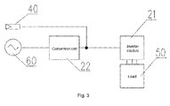
- the distributed power generation system includes the abovementioned power electronic device cooling system (not shown in the figure) and a distributed power plant 40, wherein the distributed power plant 40 supplies power to a load 50 and/or is connected to a public grid 60 for power generation through a power electronic device.
- the load 50 includes the abovementioned air conditioning unit, and may also include other electric equipment.
- the power electronic device includes an off-grid inverter 21, a converter 22 and the like.
- the off-grid inverter 21 is connected between the distributed power plant 50 and the air conditioning unit or another load, and the distributed power plant 40 supplies power to the air conditioning unit or the other load through the off-grid inverter 21.
- One end of the converter 22 is connected with the public grid 60, while the other end is connected with the distributed power plant 40 and/or the off-grid inverter 21, the distributed power plant 40 is connected to the public grid 60 for power generation through the converter 22, and the air conditioning unit or the other load may gain electricity from the public grid through the converter 22.
- the distributed power plant may be a photovoltaic power plant, a wind power plant, a wind-solar power plant, a biomass power plant and the like, and is preferably a photovoltaic power plant.
- the distributed power generation system provided by the invention has a power electronic device cooling unit, so that reliability of the distributed power generation system may be improved, service life of the distributed power generation system may be prolonged, and a type selection requirement of the power electronic device may be lowered.
Landscapes
- Engineering & Computer Science (AREA)
- Microelectronics & Electronic Packaging (AREA)
- Physics & Mathematics (AREA)
- Thermal Sciences (AREA)
- Mechanical Engineering (AREA)
- General Engineering & Computer Science (AREA)
- Cooling Or The Like Of Electrical Apparatus (AREA)
- Inverter Devices (AREA)
Abstract
Description
- The invention relates to the technical fields of cooling and power electronics, and in particular to a power electronic device cooling system and a distributed power generation system.
- A power electronic device with high heat loss is required to be cooled, an air cooling manner is usually adopted for a power electronic device at present, and is implemented by mounting a facility such as a blower and a fan for cooling, but its cooling effect is poor, and there exists many problems; a cooling speed of air cooling is low, and the blower is large in size, which may cause a large size of the whole equipment; a large air volume may cause loud noise produced by the blower; reliability of components of the power electronic device is influenced by dust accumulation; the cooling blower is poor in adjustability, high in energy consumption and energy-consuming; and temperature of a mounting environment of the power electronic device is increased by exhaust of the blower, so that it is necessary to add a corresponding air conditioning system in a machine room.
- In order to overcome shortcomings of a conventional art, the invention provides a power electronic device cooling system, to solve the problem of poor power electronic device cooling effect in the conventional art.
- In order to achieve the purpose, the invention provides technical solutions as follows.
- A power electronic device cooling system is provided, which includes an air conditioning unit, a coolant pump, a bypass throttling element and a cooler, wherein the air conditioning unit includes an evaporator, a compressor, a first condenser and a main branch throttling element which are connected into an air conditioning cooling circulation system, the first condenser, the coolant pump, the bypass throttling element, the cooler and the evaporator are sequentially communicated, an inlet of the coolant pump is communicated with the first condenser, an outlet of the coolant pump is communicated with a first end of the bypass throttling element, a second end of the bypass throttling element is communicated with a first end of the cooler, a second end of the cooler is communicated with the evaporator, and the cooler exchanges heat with a power electronic device to cool the power electronic device.
- Furthermore, the power electronic device cooling system further includes a one-way valve, and an inlet of the one-way valve is communicated with the first condenser, and an outlet is communicated with the first end of the bypass throttling element.
- Furthermore, the power electronic device cooling system further includes a second condenser, and the second condenser is connected between the cooler and the evaporator.
- Furthermore, the power electronic device cooling system includes multiple cooling branches, each cooling branch includes a bypass throttling element and at least one cooler, an inlet of each cooling branch is communicated with the outlet of the coolant pump and the outlet of the one-way valve, and an outlet of each cooling branch is communicated with the second condenser.
- Furthermore, the bypass throttling element is one or a combination of two or more of a capillary tube, a throttling orifice plate, a thermal expansion valve and an electronic expansion valve.
- Furthermore, the air conditioning unit is a water-cooled air conditioning unit.
- Furthermore, the power electronic device includes a rectifier module and an inverter module, the cooling branches include a first cooling branch and a second cooling branch, the first cooling branch is configured to cool the rectifier module, and the second cooling branch is configured to cool the inverter module.
- Furthermore, the power electronic device further includes a reactor, and the cooling branches further include a third cooling branch configured to cool the reactor.
- Furthermore, the first cooling branch includes a first branch throttling element, the second cooling branch includes a second branch throttling element, the third cooling branch includes a third branch throttling element, the first throttling element and the second throttling element are adjustable throttling elements, and the third cooling throttling element is a fixed-proportion throttling element.
- The invention further provides a distributed power generation system, which includes a power electronic device cooling system and a distributed power plant, wherein the power electronic device cooling system is the abovementioned power electronic device cooling system, the distributed power generation system supplies power to a load and/or performs grid-connected power generation through a power electronic device, and the load includes an air conditioning unit.
- Furthermore, the power electronic device includes an off-grid inverter, and the distributed power plant is connected with the off-grid inverter, and supplies power to the air conditioning unit through the off-grid inverter.
- Furthermore, the power electronic device further includes a converter, and one end of the converter is connected with a public grid, while the other end is connected with the distributed power plant and/or the off-grid inverter.
- The invention has beneficial effects as follows: compared with air cooling and water cooling, coolant cooling has the advantages of good cooling effect and high cooling efficiency; an air cooling system is eliminated, so that small equipment size and reduction in noise are ensured; a coolant of the air conditioning unit is utilized to finish cooling cycles, so that the power electronic device may be located in a sealed environment and prevented from influence of dust, and is internally clean and long in operation life; and influence of starting and stopping of the air conditioning unit is eliminated.
-
-
Fig. 1 is a structure diagram of a power electronic device cooling system according to embodiment 1 of the invention; -
Fig. 2 is a structure diagram of a power electronic device cooling system with multiple cooling branches according to embodiment 1 of the invention; and -
Fig. 3 is a structure diagram of a distributed power generation system according to embodiment 2 of the invention. - In order to make the purpose, technical solutions and advantages of the invention clearer, the invention will be further described below with reference to the drawings and embodiments in detail. It should be understood that specific embodiments described here are only adopted to explain the invention and not intended to limit the invention.
- A power electronic device cooling system of the embodiment includes an air conditioning unit part and a power electronic device cooling circulation part, and
Fig. 1 is a structure diagram of a power electronic device cooling system according to the embodiment. Wherein an air conditioning unit includes anevaporator 11, acompressor 12, afirst condenser 13 and a mainbranch throttling element 14, an air suction port of thecompressor 12 is communicated with one end of theevaporator 11 through an air suction pipeline, an exhaust port of thecompressor 12 is communicated with one end of thefirst condenser 13 through an exhaust pipeline, and the other end of theevaporator 11 is communicated with the other end of thefirst condenser 13 through the mainbranch throttling element 14. - The power electronic device cooling circulation part includes a
coolant pump 31, abypass throttling element 32 and a cooler (not shown in the figure). An inlet of thecoolant pump 31 is communicated with a liquid outlet pipe of thefirst condenser 13, an outlet of thecoolant pump 31 is communicated with a first end of thebypass throttling element 32, a second end of thebypass throttling element 32 is communicated with a first end of the cooler, and a second end of the cooler is communicated with theevaporator 11. The cooler contacts with or gets close to a power electronic device to carry away heat of the power electronic device to cool the power electronic device through a low-temperature coolant circulated in the cooler. - When the air conditioning unit is stopped, the
coolant pump 31 is started to provide power for coolant circulation. Thecoolant pump 31 pumps the liquid coolant in thefirst condenser 13 to thebypass throttling element 32, and the coolant finally flows into theevaporator 11 to finish a cooling cycle after throttling and heat absorption evaporation. By the solution, the power electronic device is cooled when the air conditioning unit is stopped. - In order to cool the power electronic device when the air conditioning unit is started, a coolant circulation pipeline connected in parallel with the
coolant pump 31 is also arranged between thefirst condenser 13 and thebypass throttling element 32. Preferably, a one-way valve 34 is arranged on the coolant circulation pipeline, and an inlet end of the one-way valve 34 is communicated with thefirst condenser 13, while an outlet end is communicated with the first end of thebypass throttling element 32. The one-way valve 34 may effectively prevent bypass short-circuit of the coolant and ensure that the power electronic device has sufficient coolant flow. - When the air conditioning unit is started to operate, since condensing side pressure is far higher than evaporation side pressure, the liquid coolant in the
first condenser 13 is throttled by thebypass throttling element 32 under the action of pressure of the coolant in the air conditioning unit, absorbs heat to be evaporated at the cooler, and finally flows into theevaporator 11 to finish a cooling cycle. - After the coolant flows through the power electronic device, a large amount of heat may be absorbed, and may finally be accumulated in the coolant of the air conditioning unit to cause continuous increase of system temperature and system pressure of the air conditioning unit in a shutdown state if not being released. If the cooling system works for long in the shutdown state of the air conditioning unit, the system temperature is continuously increased, which may cause influence on a cooling effect of the power electronic device, and the system pressure is continuously increased, which may cause influence on safety of the whole cooling circulation system. Preferably, a
second condenser 33 is arranged between the cooler and theevaporator 11, the low-temperature coolant flowing out of thebypass throttling element 32 absorbs heat dissipated by the power electronic device to be evaporated into coolant vapor at higher temperature at the cooler, and the coolant vapor exchanges heat with air or water to release heat to be condensed into a liquid coolant again when flowing to the second condenser, and the liquid coolant enters theevaporator 11, and returns to the air conditioning unit to finish a cooling cycle. - A function of the
second condenser 33 is to improve reliability of the system and enable the cooling system to normally work for a long time in the shutdown state of the air conditioning unit. In addition, when the air conditioning unit is started to work, thesecond condenser 33 may also prevent a great amount of heat from entering theevaporator 11 to reduce energy efficiency of the air conditioning unit. Thesecond condenser 33 usually adopts a finned tube heat exchanger or a plate heat exchanger. - Wherein, the cooler is a metal cooling plate into which a coolant flow passage is embedded, the metal cooling plate contacts with the power electronic device, a proper cooler type may also be selected according to a factor such as a field environment condition and a shape and cooling requirement of the power electronic device, and for example, for a device incapable of contact heat exchange or with a low cooling requirement, a finned tube heat exchanger, a plate-fin heat exchanger or the like may be adopted as the cooler.
- If cooling may not be implemented by one cooler in case of more power electronic devices to be cooled or due to structure limits, multiple coolers are connected in series on a pipeline between the
bypass throttling element 32 and thesecond condenser 33 or multiple parallel cooling branches are arranged between thecoolant pump 31 and thesecond condenser 33, and abypass throttling element 32 and at least one cooler are arranged on each cooling branch. Thebypass throttling elements 32 may adopt throttling valves in different forms, such as capillary tubes, throttling orifice plates (fixed or variable), thermal expansion valves or electronic expansion valves, and combinations of two or more than two of the throttling valves. -
Fig. 2 is a structure diagram of a power electronic device cooling system adopting multi-branch cooling. The coolant discharged by thecoolant pump 31 and/or the one-way valve 34 enters three cooling branches after being divided by a flow division device, abypass throttling element 32 and at least one cooler being arranged on each branch. Specifically, the power electronic device is a converter, and includes a rectifier module, an inverter module and a reactor. The rectifier module and the inverter module have higher cooling requirements, a firstbypass throttling element 32a and a secondbypass throttling element 32b arranged on two branches are adjustable throttling elements, such as electronic expansion valves, and openings of the electronic expansion valves are regulated according to actual temperature of the rectifier module and the inverter module to obtain a proper coolant flow. A thirdbypass throttling element 32c located on the other branch may adopt a fixed throttling element, such as a fixed orifice plate or a capillary tube, and optimal throttling elements are matched according to system performance. Wherein, the coolers configured to cool the rectifier module and the inverter module are metal cooling plate structures with coolant circulation pipelines, the rectifier module and the inverter module contact with the metal cooling plates, and compared with an air cooling manner, such a cooling manner has a better cooling effect, is high in cooling speed and cooling efficiency and may greatly reduce a size of the converter and lower a type selection requirement of the elements. - The air conditioning unit is preferably a central air conditioning unit, the central air conditioning unit having high coolant storage capacity sufficient to meet a cooling requirement, is further a water-cooled air conditioning unit, and furthermore, is a centrifugal water-cooled unit or a screw water-cooled unit.
- The power electronic device in the embodiment may be a power electronic device which keeps normal operation of the air conditioning unit, and may also be a power electronic device in other equipment.
- From the above, the cooling system provided by the invention well solves a cooling problem of the power electronic device, and a cooling capability of the coolant is higher than those of air cooling and water cooling; the solution is free of influence of starting and stopping of the air conditioning unit, and when the air conditioning unit is stopped, the cooling requirement may also be met; a coolant flow of each branch may also be regulated according to the cooling requirement; the coolant is an insulator, and is free of short circuit or a hidden electric leakage danger and high in safety; and the coolant of the air conditioning unit is utilized to finish the cooling cycles, so that the power electronic device may be located in a sealed environment and prevented from influence of dust, and is internally clean and long in operation life.
- The invention also provides a distributed power generation system. As shown in
Fig. 3 , the distributed power generation system includes the abovementioned power electronic device cooling system (not shown in the figure) and adistributed power plant 40, wherein thedistributed power plant 40 supplies power to aload 50 and/or is connected to apublic grid 60 for power generation through a power electronic device. Theload 50 includes the abovementioned air conditioning unit, and may also include other electric equipment. The power electronic device includes an off-grid inverter 21, aconverter 22 and the like. The off-grid inverter 21 is connected between thedistributed power plant 50 and the air conditioning unit or another load, and thedistributed power plant 40 supplies power to the air conditioning unit or the other load through the off-grid inverter 21. One end of theconverter 22 is connected with thepublic grid 60, while the other end is connected with thedistributed power plant 40 and/or the off-grid inverter 21, thedistributed power plant 40 is connected to thepublic grid 60 for power generation through theconverter 22, and the air conditioning unit or the other load may gain electricity from the public grid through theconverter 22. - Specifically, the distributed power plant may be a photovoltaic power plant, a wind power plant, a wind-solar power plant, a biomass power plant and the like, and is preferably a photovoltaic power plant.
- The distributed power generation system provided by the invention has a power electronic device cooling unit, so that reliability of the distributed power generation system may be improved, service life of the distributed power generation system may be prolonged, and a type selection requirement of the power electronic device may be lowered.
- The abovementioned embodiments only represent some implementation modes of the invention, are specifically described in detail, but may not thus be understood as limits to the scope of the invention. It should be pointed out that those skilled in the art may also make various transformations and improvements without departing from the concept of the invention, and these transformations and improvements all fall within the scope of protection of the invention. Therefore, the scope of protection of the invention should be subject to the appended claims.
Claims (12)
- A power electronic device cooling system, comprising:an air conditioning unit, a coolant pump, a bypass throttling element and a cooler,wherein the air conditioning unit comprises an evaporator, a compressor, a first condenser and a main branch throttling element which are connected into an air conditioning cooling circulation system,the first condenser, the coolant pump, the bypass throttling element, the cooler and the evaporator are sequentially communicated,an inlet of the coolant pump is communicated with the first condenser, an outlet of the coolant pump is communicated with a first end of the bypass throttling element, a second end of the bypass throttling element is communicated with a first end of the cooler, a second end of the cooler is communicated with the evaporator, and the cooler exchanges heat with a power electronic device to cool the power electronic device.
- The power electronic device cooling system according to claim 1, further comprising a one-way valve, wherein an inlet of the one-way valve is communicated with the first condenser, and an outlet is communicated with the first end of the bypass throttling element.
- The power electronic device cooling system according to claim 1 or 2, further comprising a second condenser, wherein the second condenser is connected between the cooler and the evaporator.
- The power electronic device cooling system according to claim 3, comprising multiple cooling branches, wherein each cooling branch comprises a bypass throttling element and at least one cooler, an inlet of each cooling branch is communicated with the outlet of the coolant pump and the outlet of the one-way valve, and an outlet of each cooling branch is communicated with the second condenser.
- The power electronic device cooling system according to claim 3, wherein the bypass throttling element is one or a combination of two or more of a capillary tube, a throttling orifice plate, a thermal expansion valve and an electronic expansion valve.
- The power electronic device cooling system according to claim 3, wherein the air conditioning unit is a water-cooled air conditioning unit.
- The power electronic device cooling system according to claim 4, wherein the power electronic device comprises a rectifier module and an inverter module, the cooling branches comprise a first cooling branch and a second cooling branch, the first cooling branch is configured to cool the rectifier module, and the second cooling branch is configured to cool the inverter module.
- The power electronic device cooling system according to claim 7, wherein the power electronic device further comprises a reactor, and the cooling branches further comprise a third cooling branch configured to cool the reactor.
- The power electronic device cooling system according to claim 8, wherein the first cooling branch comprises a first branch throttling element, the second cooling branch comprises a second branch throttling element, the third cooling branch comprises a third branch throttling element, the first throttling element and the second throttling element are adjustable throttling elements, and the third cooling throttling element is a fixed-proportion throttling element.
- A distributed power generation system, comprising a power electronic device cooling system and a distributed power plant, wherein the power electronic device cooling system is the power electronic device cooling system according to any one of claims 1 to 9, the distributed power generation system supplies power to a load and/or performs grid-connected power generation through a power electronic device, and the load comprises an air conditioning unit.
- The distributed power generation system according to claim 10, wherein the power electronic device comprises an off-grid inverter, and the distributed power plant is connected with the off-grid inverter, and supplies power to the air conditioning unit through the off-grid inverter.
- The distributed power generation system according to claim 11, wherein the power electronic device further comprises a converter, and one end of the converter is connected with a public grid, while the other end is connected with the distributed power plant and/or the off-grid inverter.
Applications Claiming Priority (2)
| Application Number | Priority Date | Filing Date | Title |
|---|---|---|---|
| CN201310442148.6A CN103486752A (en) | 2013-09-25 | 2013-09-25 | Power electronic device cooling system and distributed power generation system |
| PCT/CN2014/080764 WO2015043259A1 (en) | 2013-09-25 | 2014-06-25 | Cooling system for power electronic device, and distributed power generation system |
Publications (3)
| Publication Number | Publication Date |
|---|---|
| EP3051226A1 true EP3051226A1 (en) | 2016-08-03 |
| EP3051226A4 EP3051226A4 (en) | 2017-08-23 |
| EP3051226B1 EP3051226B1 (en) | 2019-10-02 |
Family
ID=49827188
Family Applications (1)
| Application Number | Title | Priority Date | Filing Date |
|---|---|---|---|
| EP14847761.5A Active EP3051226B1 (en) | 2013-09-25 | 2014-06-25 | Cooling system for power electronic device, and distributed power generation system |
Country Status (8)
| Country | Link |
|---|---|
| US (1) | US10356962B2 (en) |
| EP (1) | EP3051226B1 (en) |
| JP (1) | JP6271026B2 (en) |
| CN (1) | CN103486752A (en) |
| ES (1) | ES2751455T3 (en) |
| MY (1) | MY184272A (en) |
| PH (1) | PH12016500561A1 (en) |
| WO (1) | WO2015043259A1 (en) |
Cited By (1)
| Publication number | Priority date | Publication date | Assignee | Title |
|---|---|---|---|---|
| CN107228455A (en) * | 2017-06-09 | 2017-10-03 | 青岛海尔空调器有限总公司 | A kind of air conditioner and control method |
Families Citing this family (20)
| Publication number | Priority date | Publication date | Assignee | Title |
|---|---|---|---|---|
| CN103486752A (en) | 2013-09-25 | 2014-01-01 | 珠海格力电器股份有限公司 | Power electronic device cooling system and distributed power generation system |
| CN105658018B (en) * | 2014-08-14 | 2018-07-10 | 上海绿凡电力科技有限公司 | A kind of two-phase cooling system based on R134a |
| CN104362836B (en) * | 2014-11-25 | 2016-06-08 | 南车株洲电力机车研究所有限公司 | A kind of heat management system for electric locomotive traction current transformer |
| CN104362835B (en) * | 2014-11-25 | 2016-03-23 | 南车株洲电力机车研究所有限公司 | A kind of heat management system for motor train traction |
| CN104362837B (en) * | 2014-11-25 | 2016-11-09 | 南车株洲电力机车研究所有限公司 | A kind of current transformer cooling system |
| KR101744536B1 (en) * | 2015-02-09 | 2017-06-08 | 엘지전자 주식회사 | Radiant heat unit and Outdoor unit of air conditioner having the same |
| CN104807114B (en) * | 2015-03-19 | 2018-08-03 | 珠海格力电器股份有限公司 | Cooling system and air conditioning system |
| CN104833012A (en) * | 2015-04-29 | 2015-08-12 | 美的集团武汉制冷设备有限公司 | Air conditioner |
| CN105241051A (en) * | 2015-09-24 | 2016-01-13 | 广东美的制冷设备有限公司 | Air conditioner |
| US20210207850A1 (en) * | 2016-01-25 | 2021-07-08 | Smardt Chiller Group Inc. | Solar integrated chiller method and system |
| CN205985267U (en) * | 2016-08-24 | 2017-02-22 | 上海蔚来汽车有限公司 | A phase change cooling system for electric automobile power battery |
| CN110410878B (en) * | 2019-08-26 | 2020-07-14 | 珠海格力电器股份有限公司 | Air conditioning system and cooling method |
| JP6878550B2 (en) * | 2019-10-31 | 2021-05-26 | 三菱重工サーマルシステムズ株式会社 | Refrigerator |
| CN111578464B (en) * | 2020-04-13 | 2021-09-03 | 海信(山东)空调有限公司 | Air conditioner |
| CN112689441B (en) * | 2020-12-10 | 2022-04-22 | 湖南文理学院 | Multichannel intercommunication formula air cycle device based on dysmorphism structure machine case |
| CN112556227A (en) * | 2020-12-22 | 2021-03-26 | 珠海格力电器股份有限公司 | Air conditioning unit, frequency converter cooling system and control method thereof |
| CN112930083A (en) * | 2021-01-22 | 2021-06-08 | 淮南师范学院 | Power electronic device with cooling structure |
| CN112944517B (en) * | 2021-03-11 | 2024-10-22 | 珠海格力电器股份有限公司 | Photovoltaic air conditioner heat dissipation system and heat dissipation control method and device thereof |
| CN113074473B (en) * | 2021-03-17 | 2022-06-28 | 中国电子科技集团公司第二十九研究所 | Consumable evaporative refrigeration device and method of use |
| CN115734581B (en) * | 2022-11-24 | 2025-09-05 | 珠海格力电器股份有限公司 | Cooling method, device and system for air conditioner inverter, and air conditioner equipment |
Family Cites Families (23)
| Publication number | Priority date | Publication date | Assignee | Title |
|---|---|---|---|---|
| SE505455C2 (en) * | 1993-12-22 | 1997-09-01 | Ericsson Telefon Ab L M | Cooling system for air with two parallel cooling circuits |
| EP0800940A3 (en) * | 1996-04-10 | 2001-06-06 | Denso Corporation | Vehicular air conditioning system for electric vehicles |
| JP3952545B2 (en) | 1997-07-24 | 2007-08-01 | 株式会社デンソー | Air conditioner for vehicles |
| JP3591304B2 (en) | 1998-05-25 | 2004-11-17 | 株式会社日本自動車部品総合研究所 | Heating element cooling device |
| US6116040A (en) * | 1999-03-15 | 2000-09-12 | Carrier Corporation | Apparatus for cooling the power electronics of a refrigeration compressor drive |
| US6989989B2 (en) | 2003-06-17 | 2006-01-24 | Utc Power Llc | Power converter cooling |
| ITPD20060006A1 (en) * | 2006-01-05 | 2007-07-06 | Liebert Hiross Spa | UPS' |
| US8156757B2 (en) * | 2006-10-06 | 2012-04-17 | Aff-Mcquay Inc. | High capacity chiller compressor |
| JP5446064B2 (en) * | 2006-11-13 | 2014-03-19 | ダイキン工業株式会社 | Heat exchange system |
| CN101309578A (en) * | 2008-06-19 | 2008-11-19 | 江苏永昇空调有限公司 | Ground cooling apparatus of airborne electronic apparatus |
| JP5455431B2 (en) * | 2009-05-15 | 2014-03-26 | 三菱重工業株式会社 | Inverter cooling device, inverter cooling method, and refrigerator |
| JP5433387B2 (en) * | 2009-11-30 | 2014-03-05 | 株式会社日立製作所 | Vehicle equipment cooling and heating system |
| JP2011117677A (en) * | 2009-12-04 | 2011-06-16 | Daikin Industries Ltd | Outdoor unit for air conditioning device |
| JP5126308B2 (en) * | 2010-07-09 | 2013-01-23 | ソニー株式会社 | Power control device |
| JP5505276B2 (en) * | 2010-11-24 | 2014-05-28 | パナソニック株式会社 | Component mounting equipment |
| US8994199B2 (en) * | 2011-02-18 | 2015-03-31 | General Electric Company | System and method for determining conductive state of a solid state semiconductor device |
| JP2012172917A (en) * | 2011-02-22 | 2012-09-10 | Nippon Soken Inc | Cooling device |
| JP5786615B2 (en) | 2011-09-30 | 2015-09-30 | ダイキン工業株式会社 | Automotive temperature control system |
| JP5831108B2 (en) * | 2011-09-30 | 2015-12-09 | ダイキン工業株式会社 | Automotive temperature control system |
| JP2013117360A (en) * | 2011-12-05 | 2013-06-13 | Hitachi Appliances Inc | Air conditioning device and method |
| US9845977B2 (en) * | 2011-12-23 | 2017-12-19 | Schneider Electric It Corporation | Systems and methods for computer room air conditioning |
| CN103486752A (en) | 2013-09-25 | 2014-01-01 | 珠海格力电器股份有限公司 | Power electronic device cooling system and distributed power generation system |
| CN203518304U (en) * | 2013-09-25 | 2014-04-02 | 珠海格力电器股份有限公司 | Power electronic device cooling system and distributed power generation system |
-
2013
- 2013-09-25 CN CN201310442148.6A patent/CN103486752A/en active Pending
-
2014
- 2014-06-25 US US15/024,473 patent/US10356962B2/en active Active
- 2014-06-25 MY MYPI2016000544A patent/MY184272A/en unknown
- 2014-06-25 ES ES14847761T patent/ES2751455T3/en active Active
- 2014-06-25 JP JP2016544698A patent/JP6271026B2/en active Active
- 2014-06-25 EP EP14847761.5A patent/EP3051226B1/en active Active
- 2014-06-25 WO PCT/CN2014/080764 patent/WO2015043259A1/en not_active Ceased
-
2016
- 2016-03-28 PH PH12016500561A patent/PH12016500561A1/en unknown
Cited By (1)
| Publication number | Priority date | Publication date | Assignee | Title |
|---|---|---|---|---|
| CN107228455A (en) * | 2017-06-09 | 2017-10-03 | 青岛海尔空调器有限总公司 | A kind of air conditioner and control method |
Also Published As
| Publication number | Publication date |
|---|---|
| US10356962B2 (en) | 2019-07-16 |
| EP3051226B1 (en) | 2019-10-02 |
| WO2015043259A1 (en) | 2015-04-02 |
| PH12016500561B1 (en) | 2016-05-23 |
| US20160219759A1 (en) | 2016-07-28 |
| JP6271026B2 (en) | 2018-01-31 |
| JP2016534319A (en) | 2016-11-04 |
| MY184272A (en) | 2021-03-30 |
| ES2751455T3 (en) | 2020-03-31 |
| CN103486752A (en) | 2014-01-01 |
| PH12016500561A1 (en) | 2016-05-23 |
| EP3051226A4 (en) | 2017-08-23 |
Similar Documents
| Publication | Publication Date | Title |
|---|---|---|
| US10356962B2 (en) | Power electronic device cooling system and distributed power generation system | |
| EP3051217B1 (en) | Photovoltaic air conditioning system | |
| US10356949B2 (en) | Server rack heat sink system with combination of liquid cooling device and auxiliary heat sink device | |
| CN107182191B (en) | System capable of simultaneously realizing heat dissipation of CPU chip and server | |
| CN110278691A (en) | Pump-Driven Two-Phase Loop Cooling System for High Power Density Cabinets | |
| CN114071972A (en) | Pump-driving double-loop heat pipe combined heat dissipation system for high-power-density cabinet | |
| CN204598537U (en) | A kind of cooling system of rack | |
| CN102281742A (en) | Closed cabinet body cooling system and wind generating set | |
| CN203633039U (en) | air conditioning unit | |
| CN116885331A (en) | An energy storage battery temperature control system and energy storage battery cabinet | |
| CN113631019A (en) | An evaporative cooling system for high power converters | |
| CN114867312A (en) | Heat recovery type liquid cooling system | |
| CN104633873A (en) | Air conditioning unit | |
| CN203518304U (en) | Power electronic device cooling system and distributed power generation system | |
| US20230118671A1 (en) | Photovoltaic air conditioning system | |
| CN212786442U (en) | Unit formula converter evaporative cooling device | |
| CN215529758U (en) | Cooling unit and data center having the same | |
| CN207117010U (en) | SVG is cooled down and afterheat utilizing system | |
| CN222775395U (en) | Heat exchange device for energy storage device and energy storage device having the same | |
| CN222964160U (en) | Direct cooling type heat management system and energy storage system applying same | |
| CN223039004U (en) | A cooling system for improving the heat exchange efficiency of PCS energy storage equipment | |
| CN222352673U (en) | Cold and hot control system of kitchen | |
| CN116367494B (en) | A cooling system for a power module and a control method thereof | |
| CN219248411U (en) | Refrigerating system and equipment with refrigerating device | |
| CN201463386U (en) | A dual cooling chiller |
Legal Events
| Date | Code | Title | Description |
|---|---|---|---|
| PUAI | Public reference made under article 153(3) epc to a published international application that has entered the european phase |
Free format text: ORIGINAL CODE: 0009012 |
|
| 17P | Request for examination filed |
Effective date: 20160415 |
|
| AK | Designated contracting states |
Kind code of ref document: A1 Designated state(s): AL AT BE BG CH CY CZ DE DK EE ES FI FR GB GR HR HU IE IS IT LI LT LU LV MC MK MT NL NO PL PT RO RS SE SI SK SM TR |
|
| AX | Request for extension of the european patent |
Extension state: BA ME |
|
| DAX | Request for extension of the european patent (deleted) | ||
| A4 | Supplementary search report drawn up and despatched |
Effective date: 20170724 |
|
| RIC1 | Information provided on ipc code assigned before grant |
Ipc: H05K 7/20 20060101ALI20170718BHEP Ipc: F25B 1/00 20060101AFI20170718BHEP |
|
| STAA | Information on the status of an ep patent application or granted ep patent |
Free format text: STATUS: EXAMINATION IS IN PROGRESS |
|
| 17Q | First examination report despatched |
Effective date: 20180926 |
|
| GRAP | Despatch of communication of intention to grant a patent |
Free format text: ORIGINAL CODE: EPIDOSNIGR1 |
|
| STAA | Information on the status of an ep patent application or granted ep patent |
Free format text: STATUS: GRANT OF PATENT IS INTENDED |
|
| INTG | Intention to grant announced |
Effective date: 20190624 |
|
| GRAS | Grant fee paid |
Free format text: ORIGINAL CODE: EPIDOSNIGR3 |
|
| GRAA | (expected) grant |
Free format text: ORIGINAL CODE: 0009210 |
|
| STAA | Information on the status of an ep patent application or granted ep patent |
Free format text: STATUS: THE PATENT HAS BEEN GRANTED |
|
| AK | Designated contracting states |
Kind code of ref document: B1 Designated state(s): AL AT BE BG CH CY CZ DE DK EE ES FI FR GB GR HR HU IE IS IT LI LT LU LV MC MK MT NL NO PL PT RO RS SE SI SK SM TR |
|
| REG | Reference to a national code |
Ref country code: GB Ref legal event code: FG4D |
|
| REG | Reference to a national code |
Ref country code: CH Ref legal event code: EP Ref country code: AT Ref legal event code: REF Ref document number: 1186623 Country of ref document: AT Kind code of ref document: T Effective date: 20191015 |
|
| REG | Reference to a national code |
Ref country code: DE Ref legal event code: R096 Ref document number: 602014054718 Country of ref document: DE |
|
| REG | Reference to a national code |
Ref country code: IE Ref legal event code: FG4D |
|
| REG | Reference to a national code |
Ref country code: DE Ref legal event code: R082 Ref document number: 602014054718 Country of ref document: DE Representative=s name: STRAUS, ALEXANDER, DIPL.-CHEM.UNIV. DR.PHIL., DE Ref country code: DE Ref legal event code: R082 Ref document number: 602014054718 Country of ref document: DE Representative=s name: 2K PATENT- UND RECHTSANWAELTE PARTNERSCHAFT MB, DE |
|
| REG | Reference to a national code |
Ref country code: NL Ref legal event code: MP Effective date: 20191002 |
|
| REG | Reference to a national code |
Ref country code: LT Ref legal event code: MG4D |
|
| REG | Reference to a national code |
Ref country code: ES Ref legal event code: FG2A Ref document number: 2751455 Country of ref document: ES Kind code of ref document: T3 Effective date: 20200331 |
|
| REG | Reference to a national code |
Ref country code: AT Ref legal event code: MK05 Ref document number: 1186623 Country of ref document: AT Kind code of ref document: T Effective date: 20191002 |
|
| PG25 | Lapsed in a contracting state [announced via postgrant information from national office to epo] |
Ref country code: PT Free format text: LAPSE BECAUSE OF FAILURE TO SUBMIT A TRANSLATION OF THE DESCRIPTION OR TO PAY THE FEE WITHIN THE PRESCRIBED TIME-LIMIT Effective date: 20200203 Ref country code: FI Free format text: LAPSE BECAUSE OF FAILURE TO SUBMIT A TRANSLATION OF THE DESCRIPTION OR TO PAY THE FEE WITHIN THE PRESCRIBED TIME-LIMIT Effective date: 20191002 Ref country code: BG Free format text: LAPSE BECAUSE OF FAILURE TO SUBMIT A TRANSLATION OF THE DESCRIPTION OR TO PAY THE FEE WITHIN THE PRESCRIBED TIME-LIMIT Effective date: 20200102 Ref country code: NO Free format text: LAPSE BECAUSE OF FAILURE TO SUBMIT A TRANSLATION OF THE DESCRIPTION OR TO PAY THE FEE WITHIN THE PRESCRIBED TIME-LIMIT Effective date: 20200102 Ref country code: LT Free format text: LAPSE BECAUSE OF FAILURE TO SUBMIT A TRANSLATION OF THE DESCRIPTION OR TO PAY THE FEE WITHIN THE PRESCRIBED TIME-LIMIT Effective date: 20191002 Ref country code: PL Free format text: LAPSE BECAUSE OF FAILURE TO SUBMIT A TRANSLATION OF THE DESCRIPTION OR TO PAY THE FEE WITHIN THE PRESCRIBED TIME-LIMIT Effective date: 20191002 Ref country code: GR Free format text: LAPSE BECAUSE OF FAILURE TO SUBMIT A TRANSLATION OF THE DESCRIPTION OR TO PAY THE FEE WITHIN THE PRESCRIBED TIME-LIMIT Effective date: 20200103 Ref country code: SE Free format text: LAPSE BECAUSE OF FAILURE TO SUBMIT A TRANSLATION OF THE DESCRIPTION OR TO PAY THE FEE WITHIN THE PRESCRIBED TIME-LIMIT Effective date: 20191002 Ref country code: LV Free format text: LAPSE BECAUSE OF FAILURE TO SUBMIT A TRANSLATION OF THE DESCRIPTION OR TO PAY THE FEE WITHIN THE PRESCRIBED TIME-LIMIT Effective date: 20191002 Ref country code: AT Free format text: LAPSE BECAUSE OF FAILURE TO SUBMIT A TRANSLATION OF THE DESCRIPTION OR TO PAY THE FEE WITHIN THE PRESCRIBED TIME-LIMIT Effective date: 20191002 Ref country code: NL Free format text: LAPSE BECAUSE OF FAILURE TO SUBMIT A TRANSLATION OF THE DESCRIPTION OR TO PAY THE FEE WITHIN THE PRESCRIBED TIME-LIMIT Effective date: 20191002 |
|
| PG25 | Lapsed in a contracting state [announced via postgrant information from national office to epo] |
Ref country code: CZ Free format text: LAPSE BECAUSE OF FAILURE TO SUBMIT A TRANSLATION OF THE DESCRIPTION OR TO PAY THE FEE WITHIN THE PRESCRIBED TIME-LIMIT Effective date: 20191002 Ref country code: IS Free format text: LAPSE BECAUSE OF FAILURE TO SUBMIT A TRANSLATION OF THE DESCRIPTION OR TO PAY THE FEE WITHIN THE PRESCRIBED TIME-LIMIT Effective date: 20200224 Ref country code: HR Free format text: LAPSE BECAUSE OF FAILURE TO SUBMIT A TRANSLATION OF THE DESCRIPTION OR TO PAY THE FEE WITHIN THE PRESCRIBED TIME-LIMIT Effective date: 20191002 Ref country code: RS Free format text: LAPSE BECAUSE OF FAILURE TO SUBMIT A TRANSLATION OF THE DESCRIPTION OR TO PAY THE FEE WITHIN THE PRESCRIBED TIME-LIMIT Effective date: 20191002 |
|
| PG25 | Lapsed in a contracting state [announced via postgrant information from national office to epo] |
Ref country code: AL Free format text: LAPSE BECAUSE OF FAILURE TO SUBMIT A TRANSLATION OF THE DESCRIPTION OR TO PAY THE FEE WITHIN THE PRESCRIBED TIME-LIMIT Effective date: 20191002 |
|
| REG | Reference to a national code |
Ref country code: DE Ref legal event code: R097 Ref document number: 602014054718 Country of ref document: DE |
|
| PG2D | Information on lapse in contracting state deleted |
Ref country code: IS |
|
| PG25 | Lapsed in a contracting state [announced via postgrant information from national office to epo] |
Ref country code: DK Free format text: LAPSE BECAUSE OF FAILURE TO SUBMIT A TRANSLATION OF THE DESCRIPTION OR TO PAY THE FEE WITHIN THE PRESCRIBED TIME-LIMIT Effective date: 20191002 Ref country code: EE Free format text: LAPSE BECAUSE OF FAILURE TO SUBMIT A TRANSLATION OF THE DESCRIPTION OR TO PAY THE FEE WITHIN THE PRESCRIBED TIME-LIMIT Effective date: 20191002 Ref country code: RO Free format text: LAPSE BECAUSE OF FAILURE TO SUBMIT A TRANSLATION OF THE DESCRIPTION OR TO PAY THE FEE WITHIN THE PRESCRIBED TIME-LIMIT Effective date: 20191002 Ref country code: IS Free format text: LAPSE BECAUSE OF FAILURE TO SUBMIT A TRANSLATION OF THE DESCRIPTION OR TO PAY THE FEE WITHIN THE PRESCRIBED TIME-LIMIT Effective date: 20200202 |
|
| PLBE | No opposition filed within time limit |
Free format text: ORIGINAL CODE: 0009261 |
|
| STAA | Information on the status of an ep patent application or granted ep patent |
Free format text: STATUS: NO OPPOSITION FILED WITHIN TIME LIMIT |
|
| PG25 | Lapsed in a contracting state [announced via postgrant information from national office to epo] |
Ref country code: SM Free format text: LAPSE BECAUSE OF FAILURE TO SUBMIT A TRANSLATION OF THE DESCRIPTION OR TO PAY THE FEE WITHIN THE PRESCRIBED TIME-LIMIT Effective date: 20191002 Ref country code: SK Free format text: LAPSE BECAUSE OF FAILURE TO SUBMIT A TRANSLATION OF THE DESCRIPTION OR TO PAY THE FEE WITHIN THE PRESCRIBED TIME-LIMIT Effective date: 20191002 Ref country code: IT Free format text: LAPSE BECAUSE OF FAILURE TO SUBMIT A TRANSLATION OF THE DESCRIPTION OR TO PAY THE FEE WITHIN THE PRESCRIBED TIME-LIMIT Effective date: 20191002 |
|
| 26N | No opposition filed |
Effective date: 20200703 |
|
| PG25 | Lapsed in a contracting state [announced via postgrant information from national office to epo] |
Ref country code: SI Free format text: LAPSE BECAUSE OF FAILURE TO SUBMIT A TRANSLATION OF THE DESCRIPTION OR TO PAY THE FEE WITHIN THE PRESCRIBED TIME-LIMIT Effective date: 20191002 |
|
| PG25 | Lapsed in a contracting state [announced via postgrant information from national office to epo] |
Ref country code: MC Free format text: LAPSE BECAUSE OF FAILURE TO SUBMIT A TRANSLATION OF THE DESCRIPTION OR TO PAY THE FEE WITHIN THE PRESCRIBED TIME-LIMIT Effective date: 20191002 |
|
| REG | Reference to a national code |
Ref country code: CH Ref legal event code: PL |
|
| PG25 | Lapsed in a contracting state [announced via postgrant information from national office to epo] |
Ref country code: LU Free format text: LAPSE BECAUSE OF NON-PAYMENT OF DUE FEES Effective date: 20200625 |
|
| REG | Reference to a national code |
Ref country code: BE Ref legal event code: MM Effective date: 20200630 |
|
| PG25 | Lapsed in a contracting state [announced via postgrant information from national office to epo] |
Ref country code: LI Free format text: LAPSE BECAUSE OF NON-PAYMENT OF DUE FEES Effective date: 20200630 Ref country code: IE Free format text: LAPSE BECAUSE OF NON-PAYMENT OF DUE FEES Effective date: 20200625 Ref country code: CH Free format text: LAPSE BECAUSE OF NON-PAYMENT OF DUE FEES Effective date: 20200630 |
|
| PG25 | Lapsed in a contracting state [announced via postgrant information from national office to epo] |
Ref country code: BE Free format text: LAPSE BECAUSE OF NON-PAYMENT OF DUE FEES Effective date: 20200630 |
|
| PG25 | Lapsed in a contracting state [announced via postgrant information from national office to epo] |
Ref country code: TR Free format text: LAPSE BECAUSE OF FAILURE TO SUBMIT A TRANSLATION OF THE DESCRIPTION OR TO PAY THE FEE WITHIN THE PRESCRIBED TIME-LIMIT Effective date: 20191002 Ref country code: MT Free format text: LAPSE BECAUSE OF FAILURE TO SUBMIT A TRANSLATION OF THE DESCRIPTION OR TO PAY THE FEE WITHIN THE PRESCRIBED TIME-LIMIT Effective date: 20191002 Ref country code: CY Free format text: LAPSE BECAUSE OF FAILURE TO SUBMIT A TRANSLATION OF THE DESCRIPTION OR TO PAY THE FEE WITHIN THE PRESCRIBED TIME-LIMIT Effective date: 20191002 |
|
| PG25 | Lapsed in a contracting state [announced via postgrant information from national office to epo] |
Ref country code: MK Free format text: LAPSE BECAUSE OF FAILURE TO SUBMIT A TRANSLATION OF THE DESCRIPTION OR TO PAY THE FEE WITHIN THE PRESCRIBED TIME-LIMIT Effective date: 20191002 |
|
| P01 | Opt-out of the competence of the unified patent court (upc) registered |
Effective date: 20230530 |
|
| REG | Reference to a national code |
Ref country code: DE Ref legal event code: R082 Ref document number: 602014054718 Country of ref document: DE Representative=s name: STRAUS, ALEXANDER, DIPL.-CHEM.UNIV. DR.PHIL., DE |
|
| PGFP | Annual fee paid to national office [announced via postgrant information from national office to epo] |
Ref country code: DE Payment date: 20250618 Year of fee payment: 12 |
|
| PGFP | Annual fee paid to national office [announced via postgrant information from national office to epo] |
Ref country code: GB Payment date: 20250508 Year of fee payment: 12 |
|
| PGFP | Annual fee paid to national office [announced via postgrant information from national office to epo] |
Ref country code: FR Payment date: 20250508 Year of fee payment: 12 |
|
| PGFP | Annual fee paid to national office [announced via postgrant information from national office to epo] |
Ref country code: ES Payment date: 20250718 Year of fee payment: 12 |