EP3051156A1 - Sintered metal bearing and fluid-dynamic bearing device provided with said bearing - Google Patents
Sintered metal bearing and fluid-dynamic bearing device provided with said bearing Download PDFInfo
- Publication number
- EP3051156A1 EP3051156A1 EP14849434.7A EP14849434A EP3051156A1 EP 3051156 A1 EP3051156 A1 EP 3051156A1 EP 14849434 A EP14849434 A EP 14849434A EP 3051156 A1 EP3051156 A1 EP 3051156A1
- Authority
- EP
- European Patent Office
- Prior art keywords
- sintered metal
- bearing
- metal bearing
- dynamic pressure
- pressure generating
- Prior art date
- Legal status (The legal status is an assumption and is not a legal conclusion. Google has not performed a legal analysis and makes no representation as to the accuracy of the status listed.)
- Granted
Links
- 239000002184 metal Substances 0.000 title claims abstract description 109
- 229910052751 metal Inorganic materials 0.000 title claims abstract description 109
- 230000002093 peripheral effect Effects 0.000 claims abstract description 45
- 239000000843 powder Substances 0.000 claims abstract description 14
- 239000002994 raw material Substances 0.000 claims abstract description 14
- 238000005245 sintering Methods 0.000 claims abstract description 9
- 238000000748 compression moulding Methods 0.000 claims abstract description 5
- 239000010687 lubricating oil Substances 0.000 claims description 41
- 238000007789 sealing Methods 0.000 claims description 10
- 238000004513 sizing Methods 0.000 description 33
- 238000000465 moulding Methods 0.000 description 24
- 239000002344 surface layer Substances 0.000 description 9
- 230000009471 action Effects 0.000 description 7
- 239000003921 oil Substances 0.000 description 6
- 239000011148 porous material Substances 0.000 description 5
- XEEYBQQBJWHFJM-UHFFFAOYSA-N Iron Chemical compound [Fe] XEEYBQQBJWHFJM-UHFFFAOYSA-N 0.000 description 4
- 230000006835 compression Effects 0.000 description 4
- 238000007906 compression Methods 0.000 description 4
- 239000012530 fluid Substances 0.000 description 4
- 230000001050 lubricating effect Effects 0.000 description 4
- 238000000034 method Methods 0.000 description 4
- 238000001816 cooling Methods 0.000 description 3
- 230000006866 deterioration Effects 0.000 description 3
- 238000004519 manufacturing process Methods 0.000 description 3
- RYGMFSIKBFXOCR-UHFFFAOYSA-N Copper Chemical compound [Cu] RYGMFSIKBFXOCR-UHFFFAOYSA-N 0.000 description 2
- 229910052802 copper Inorganic materials 0.000 description 2
- 239000010949 copper Substances 0.000 description 2
- 150000002148 esters Chemical class 0.000 description 2
- 229910052742 iron Inorganic materials 0.000 description 2
- 239000000463 material Substances 0.000 description 2
- 238000000638 solvent extraction Methods 0.000 description 2
- 229910000881 Cu alloy Inorganic materials 0.000 description 1
- 229910000640 Fe alloy Inorganic materials 0.000 description 1
- 230000003139 buffering effect Effects 0.000 description 1
- 230000015556 catabolic process Effects 0.000 description 1
- 230000008859 change Effects 0.000 description 1
- 238000006731 degradation reaction Methods 0.000 description 1
- 230000000694 effects Effects 0.000 description 1
- 238000001704 evaporation Methods 0.000 description 1
- 230000008020 evaporation Effects 0.000 description 1
- 230000005284 excitation Effects 0.000 description 1
- 230000006872 improvement Effects 0.000 description 1
- 238000010348 incorporation Methods 0.000 description 1
- 238000001746 injection moulding Methods 0.000 description 1
- 239000007788 liquid Substances 0.000 description 1
- 150000002739 metals Chemical class 0.000 description 1
- 238000012986 modification Methods 0.000 description 1
- 230000004048 modification Effects 0.000 description 1
- 230000003287 optical effect Effects 0.000 description 1
- 238000003825 pressing Methods 0.000 description 1
- 230000009467 reduction Effects 0.000 description 1
- 239000011347 resin Substances 0.000 description 1
- 229920005989 resin Polymers 0.000 description 1
- 230000000717 retained effect Effects 0.000 description 1
- 238000000926 separation method Methods 0.000 description 1
- 239000000243 solution Substances 0.000 description 1
- 239000010935 stainless steel Substances 0.000 description 1
- 229910001220 stainless steel Inorganic materials 0.000 description 1
Images

Classifications
-
- F—MECHANICAL ENGINEERING; LIGHTING; HEATING; WEAPONS; BLASTING
- F04—POSITIVE - DISPLACEMENT MACHINES FOR LIQUIDS; PUMPS FOR LIQUIDS OR ELASTIC FLUIDS
- F04D—NON-POSITIVE-DISPLACEMENT PUMPS
- F04D25/00—Pumping installations or systems
- F04D25/02—Units comprising pumps and their driving means
- F04D25/08—Units comprising pumps and their driving means the working fluid being air, e.g. for ventilation
-
- F—MECHANICAL ENGINEERING; LIGHTING; HEATING; WEAPONS; BLASTING
- F04—POSITIVE - DISPLACEMENT MACHINES FOR LIQUIDS; PUMPS FOR LIQUIDS OR ELASTIC FLUIDS
- F04D—NON-POSITIVE-DISPLACEMENT PUMPS
- F04D25/00—Pumping installations or systems
- F04D25/02—Units comprising pumps and their driving means
- F04D25/06—Units comprising pumps and their driving means the pump being electrically driven
- F04D25/0606—Units comprising pumps and their driving means the pump being electrically driven the electric motor being specially adapted for integration in the pump
- F04D25/0613—Units comprising pumps and their driving means the pump being electrically driven the electric motor being specially adapted for integration in the pump the electric motor being of the inside-out type, i.e. the rotor is arranged radially outside a central stator
- F04D25/062—Details of the bearings
-
- F—MECHANICAL ENGINEERING; LIGHTING; HEATING; WEAPONS; BLASTING
- F04—POSITIVE - DISPLACEMENT MACHINES FOR LIQUIDS; PUMPS FOR LIQUIDS OR ELASTIC FLUIDS
- F04D—NON-POSITIVE-DISPLACEMENT PUMPS
- F04D29/00—Details, component parts, or accessories
- F04D29/05—Shafts or bearings, or assemblies thereof, specially adapted for elastic fluid pumps
- F04D29/056—Bearings
-
- F—MECHANICAL ENGINEERING; LIGHTING; HEATING; WEAPONS; BLASTING
- F04—POSITIVE - DISPLACEMENT MACHINES FOR LIQUIDS; PUMPS FOR LIQUIDS OR ELASTIC FLUIDS
- F04D—NON-POSITIVE-DISPLACEMENT PUMPS
- F04D29/00—Details, component parts, or accessories
- F04D29/05—Shafts or bearings, or assemblies thereof, specially adapted for elastic fluid pumps
- F04D29/056—Bearings
- F04D29/057—Bearings hydrostatic; hydrodynamic
-
- F—MECHANICAL ENGINEERING; LIGHTING; HEATING; WEAPONS; BLASTING
- F16—ENGINEERING ELEMENTS AND UNITS; GENERAL MEASURES FOR PRODUCING AND MAINTAINING EFFECTIVE FUNCTIONING OF MACHINES OR INSTALLATIONS; THERMAL INSULATION IN GENERAL
- F16C—SHAFTS; FLEXIBLE SHAFTS; ELEMENTS OR CRANKSHAFT MECHANISMS; ROTARY BODIES OTHER THAN GEARING ELEMENTS; BEARINGS
- F16C17/00—Sliding-contact bearings for exclusively rotary movement
- F16C17/02—Sliding-contact bearings for exclusively rotary movement for radial load only
-
- F—MECHANICAL ENGINEERING; LIGHTING; HEATING; WEAPONS; BLASTING
- F16—ENGINEERING ELEMENTS AND UNITS; GENERAL MEASURES FOR PRODUCING AND MAINTAINING EFFECTIVE FUNCTIONING OF MACHINES OR INSTALLATIONS; THERMAL INSULATION IN GENERAL
- F16C—SHAFTS; FLEXIBLE SHAFTS; ELEMENTS OR CRANKSHAFT MECHANISMS; ROTARY BODIES OTHER THAN GEARING ELEMENTS; BEARINGS
- F16C17/00—Sliding-contact bearings for exclusively rotary movement
- F16C17/10—Sliding-contact bearings for exclusively rotary movement for both radial and axial load
- F16C17/102—Sliding-contact bearings for exclusively rotary movement for both radial and axial load with grooves in the bearing surface to generate hydrodynamic pressure
- F16C17/107—Sliding-contact bearings for exclusively rotary movement for both radial and axial load with grooves in the bearing surface to generate hydrodynamic pressure with at least one surface for radial load and at least one surface for axial load
-
- F—MECHANICAL ENGINEERING; LIGHTING; HEATING; WEAPONS; BLASTING
- F16—ENGINEERING ELEMENTS AND UNITS; GENERAL MEASURES FOR PRODUCING AND MAINTAINING EFFECTIVE FUNCTIONING OF MACHINES OR INSTALLATIONS; THERMAL INSULATION IN GENERAL
- F16C—SHAFTS; FLEXIBLE SHAFTS; ELEMENTS OR CRANKSHAFT MECHANISMS; ROTARY BODIES OTHER THAN GEARING ELEMENTS; BEARINGS
- F16C33/00—Parts of bearings; Special methods for making bearings or parts thereof
- F16C33/02—Parts of sliding-contact bearings
- F16C33/04—Brasses; Bushes; Linings
- F16C33/06—Sliding surface mainly made of metal
- F16C33/10—Construction relative to lubrication
- F16C33/1005—Construction relative to lubrication with gas, e.g. air, as lubricant
- F16C33/101—Details of the bearing surface, e.g. means to generate pressure such as lobes or wedges
- F16C33/1015—Pressure generating grooves
-
- F—MECHANICAL ENGINEERING; LIGHTING; HEATING; WEAPONS; BLASTING
- F16—ENGINEERING ELEMENTS AND UNITS; GENERAL MEASURES FOR PRODUCING AND MAINTAINING EFFECTIVE FUNCTIONING OF MACHINES OR INSTALLATIONS; THERMAL INSULATION IN GENERAL
- F16C—SHAFTS; FLEXIBLE SHAFTS; ELEMENTS OR CRANKSHAFT MECHANISMS; ROTARY BODIES OTHER THAN GEARING ELEMENTS; BEARINGS
- F16C33/00—Parts of bearings; Special methods for making bearings or parts thereof
- F16C33/02—Parts of sliding-contact bearings
- F16C33/04—Brasses; Bushes; Linings
- F16C33/06—Sliding surface mainly made of metal
- F16C33/10—Construction relative to lubrication
- F16C33/1025—Construction relative to lubrication with liquid, e.g. oil, as lubricant
- F16C33/103—Construction relative to lubrication with liquid, e.g. oil, as lubricant retained in or near the bearing
- F16C33/104—Construction relative to lubrication with liquid, e.g. oil, as lubricant retained in or near the bearing in a porous body, e.g. oil impregnated sintered sleeve
-
- F—MECHANICAL ENGINEERING; LIGHTING; HEATING; WEAPONS; BLASTING
- F16—ENGINEERING ELEMENTS AND UNITS; GENERAL MEASURES FOR PRODUCING AND MAINTAINING EFFECTIVE FUNCTIONING OF MACHINES OR INSTALLATIONS; THERMAL INSULATION IN GENERAL
- F16C—SHAFTS; FLEXIBLE SHAFTS; ELEMENTS OR CRANKSHAFT MECHANISMS; ROTARY BODIES OTHER THAN GEARING ELEMENTS; BEARINGS
- F16C33/00—Parts of bearings; Special methods for making bearings or parts thereof
- F16C33/02—Parts of sliding-contact bearings
- F16C33/04—Brasses; Bushes; Linings
- F16C33/06—Sliding surface mainly made of metal
- F16C33/10—Construction relative to lubrication
- F16C33/1025—Construction relative to lubrication with liquid, e.g. oil, as lubricant
- F16C33/109—Lubricant compositions or properties, e.g. viscosity
-
- F—MECHANICAL ENGINEERING; LIGHTING; HEATING; WEAPONS; BLASTING
- F16—ENGINEERING ELEMENTS AND UNITS; GENERAL MEASURES FOR PRODUCING AND MAINTAINING EFFECTIVE FUNCTIONING OF MACHINES OR INSTALLATIONS; THERMAL INSULATION IN GENERAL
- F16C—SHAFTS; FLEXIBLE SHAFTS; ELEMENTS OR CRANKSHAFT MECHANISMS; ROTARY BODIES OTHER THAN GEARING ELEMENTS; BEARINGS
- F16C33/00—Parts of bearings; Special methods for making bearings or parts thereof
- F16C33/02—Parts of sliding-contact bearings
- F16C33/04—Brasses; Bushes; Linings
- F16C33/06—Sliding surface mainly made of metal
- F16C33/12—Structural composition; Use of special materials or surface treatments, e.g. for rust-proofing
- F16C33/128—Porous bearings, e.g. bushes of sintered alloy
-
- F—MECHANICAL ENGINEERING; LIGHTING; HEATING; WEAPONS; BLASTING
- F16—ENGINEERING ELEMENTS AND UNITS; GENERAL MEASURES FOR PRODUCING AND MAINTAINING EFFECTIVE FUNCTIONING OF MACHINES OR INSTALLATIONS; THERMAL INSULATION IN GENERAL
- F16C—SHAFTS; FLEXIBLE SHAFTS; ELEMENTS OR CRANKSHAFT MECHANISMS; ROTARY BODIES OTHER THAN GEARING ELEMENTS; BEARINGS
- F16C33/00—Parts of bearings; Special methods for making bearings or parts thereof
- F16C33/02—Parts of sliding-contact bearings
- F16C33/04—Brasses; Bushes; Linings
- F16C33/06—Sliding surface mainly made of metal
- F16C33/14—Special methods of manufacture; Running-in
- F16C33/145—Special methods of manufacture; Running-in of sintered porous bearings
-
- G—PHYSICS
- G11—INFORMATION STORAGE
- G11B—INFORMATION STORAGE BASED ON RELATIVE MOVEMENT BETWEEN RECORD CARRIER AND TRANSDUCER
- G11B19/00—Driving, starting, stopping record carriers not specifically of filamentary or web form, or of supports therefor; Control thereof; Control of operating function ; Driving both disc and head
- G11B19/20—Driving; Starting; Stopping; Control thereof
- G11B19/2009—Turntables, hubs and motors for disk drives; Mounting of motors in the drive
- G11B19/2036—Motors characterized by fluid-dynamic bearings
-
- F—MECHANICAL ENGINEERING; LIGHTING; HEATING; WEAPONS; BLASTING
- F05—INDEXING SCHEMES RELATING TO ENGINES OR PUMPS IN VARIOUS SUBCLASSES OF CLASSES F01-F04
- F05D—INDEXING SCHEME FOR ASPECTS RELATING TO NON-POSITIVE-DISPLACEMENT MACHINES OR ENGINES, GAS-TURBINES OR JET-PROPULSION PLANTS
- F05D2230/00—Manufacture
- F05D2230/20—Manufacture essentially without removing material
- F05D2230/22—Manufacture essentially without removing material by sintering
-
- F—MECHANICAL ENGINEERING; LIGHTING; HEATING; WEAPONS; BLASTING
- F16—ENGINEERING ELEMENTS AND UNITS; GENERAL MEASURES FOR PRODUCING AND MAINTAINING EFFECTIVE FUNCTIONING OF MACHINES OR INSTALLATIONS; THERMAL INSULATION IN GENERAL
- F16C—SHAFTS; FLEXIBLE SHAFTS; ELEMENTS OR CRANKSHAFT MECHANISMS; ROTARY BODIES OTHER THAN GEARING ELEMENTS; BEARINGS
- F16C2202/00—Solid materials defined by their properties
- F16C2202/02—Mechanical properties
- F16C2202/10—Porosity
-
- F—MECHANICAL ENGINEERING; LIGHTING; HEATING; WEAPONS; BLASTING
- F16—ENGINEERING ELEMENTS AND UNITS; GENERAL MEASURES FOR PRODUCING AND MAINTAINING EFFECTIVE FUNCTIONING OF MACHINES OR INSTALLATIONS; THERMAL INSULATION IN GENERAL
- F16C—SHAFTS; FLEXIBLE SHAFTS; ELEMENTS OR CRANKSHAFT MECHANISMS; ROTARY BODIES OTHER THAN GEARING ELEMENTS; BEARINGS
- F16C2220/00—Shaping
- F16C2220/20—Shaping by sintering pulverised material, e.g. powder metallurgy
-
- F—MECHANICAL ENGINEERING; LIGHTING; HEATING; WEAPONS; BLASTING
- F16—ENGINEERING ELEMENTS AND UNITS; GENERAL MEASURES FOR PRODUCING AND MAINTAINING EFFECTIVE FUNCTIONING OF MACHINES OR INSTALLATIONS; THERMAL INSULATION IN GENERAL
- F16C—SHAFTS; FLEXIBLE SHAFTS; ELEMENTS OR CRANKSHAFT MECHANISMS; ROTARY BODIES OTHER THAN GEARING ELEMENTS; BEARINGS
- F16C2240/00—Specified values or numerical ranges of parameters; Relations between them
- F16C2240/40—Linear dimensions, e.g. length, radius, thickness, gap
-
- F—MECHANICAL ENGINEERING; LIGHTING; HEATING; WEAPONS; BLASTING
- F16—ENGINEERING ELEMENTS AND UNITS; GENERAL MEASURES FOR PRODUCING AND MAINTAINING EFFECTIVE FUNCTIONING OF MACHINES OR INSTALLATIONS; THERMAL INSULATION IN GENERAL
- F16C—SHAFTS; FLEXIBLE SHAFTS; ELEMENTS OR CRANKSHAFT MECHANISMS; ROTARY BODIES OTHER THAN GEARING ELEMENTS; BEARINGS
- F16C2240/00—Specified values or numerical ranges of parameters; Relations between them
- F16C2240/40—Linear dimensions, e.g. length, radius, thickness, gap
- F16C2240/70—Diameters; Radii
-
- F—MECHANICAL ENGINEERING; LIGHTING; HEATING; WEAPONS; BLASTING
- F16—ENGINEERING ELEMENTS AND UNITS; GENERAL MEASURES FOR PRODUCING AND MAINTAINING EFFECTIVE FUNCTIONING OF MACHINES OR INSTALLATIONS; THERMAL INSULATION IN GENERAL
- F16C—SHAFTS; FLEXIBLE SHAFTS; ELEMENTS OR CRANKSHAFT MECHANISMS; ROTARY BODIES OTHER THAN GEARING ELEMENTS; BEARINGS
- F16C2360/00—Engines or pumps
- F16C2360/46—Fans, e.g. ventilators
-
- F—MECHANICAL ENGINEERING; LIGHTING; HEATING; WEAPONS; BLASTING
- F16—ENGINEERING ELEMENTS AND UNITS; GENERAL MEASURES FOR PRODUCING AND MAINTAINING EFFECTIVE FUNCTIONING OF MACHINES OR INSTALLATIONS; THERMAL INSULATION IN GENERAL
- F16C—SHAFTS; FLEXIBLE SHAFTS; ELEMENTS OR CRANKSHAFT MECHANISMS; ROTARY BODIES OTHER THAN GEARING ELEMENTS; BEARINGS
- F16C2361/00—Apparatus or articles in engineering in general
-
- F—MECHANICAL ENGINEERING; LIGHTING; HEATING; WEAPONS; BLASTING
- F16—ENGINEERING ELEMENTS AND UNITS; GENERAL MEASURES FOR PRODUCING AND MAINTAINING EFFECTIVE FUNCTIONING OF MACHINES OR INSTALLATIONS; THERMAL INSULATION IN GENERAL
- F16C—SHAFTS; FLEXIBLE SHAFTS; ELEMENTS OR CRANKSHAFT MECHANISMS; ROTARY BODIES OTHER THAN GEARING ELEMENTS; BEARINGS
- F16C2370/00—Apparatus relating to physics, e.g. instruments
- F16C2370/12—Hard disk drives or the like
-
- F—MECHANICAL ENGINEERING; LIGHTING; HEATING; WEAPONS; BLASTING
- F16—ENGINEERING ELEMENTS AND UNITS; GENERAL MEASURES FOR PRODUCING AND MAINTAINING EFFECTIVE FUNCTIONING OF MACHINES OR INSTALLATIONS; THERMAL INSULATION IN GENERAL
- F16C—SHAFTS; FLEXIBLE SHAFTS; ELEMENTS OR CRANKSHAFT MECHANISMS; ROTARY BODIES OTHER THAN GEARING ELEMENTS; BEARINGS
- F16C2380/00—Electrical apparatus
- F16C2380/26—Dynamo-electric machines or combinations therewith, e.g. electro-motors and generators
-
- F—MECHANICAL ENGINEERING; LIGHTING; HEATING; WEAPONS; BLASTING
- F16—ENGINEERING ELEMENTS AND UNITS; GENERAL MEASURES FOR PRODUCING AND MAINTAINING EFFECTIVE FUNCTIONING OF MACHINES OR INSTALLATIONS; THERMAL INSULATION IN GENERAL
- F16C—SHAFTS; FLEXIBLE SHAFTS; ELEMENTS OR CRANKSHAFT MECHANISMS; ROTARY BODIES OTHER THAN GEARING ELEMENTS; BEARINGS
- F16C33/00—Parts of bearings; Special methods for making bearings or parts thereof
- F16C33/02—Parts of sliding-contact bearings
- F16C33/04—Brasses; Bushes; Linings
- F16C33/06—Sliding surface mainly made of metal
- F16C33/10—Construction relative to lubrication
- F16C33/1025—Construction relative to lubrication with liquid, e.g. oil, as lubricant
- F16C33/106—Details of distribution or circulation inside the bearings, e.g. details of the bearing surfaces to affect flow or pressure of the liquid
- F16C33/107—Grooves for generating pressure
Definitions
- the present invention relates to a sintered metal bearing , a fluid-dynamic bearing device comprising the sintered metal bearing, and a fan motor comprising the fluid-dynamic bearing device.
- a sintered metal bearing is used under a state in which a lubricating oil is impregnated into inner pores thereof.
- the lubricating oil impregnated into the sintered metal bearing seeps into a sliding portion with respect to a shaft, which is inserted along an inner periphery of the sintered metal bearing, along with relative rotation of the shaft, to thereby form an oil film.
- the sintered metal bearing is configured to rotationally support the shaft through this oil film.
- Such a sintered metal bearing has excellent rotational accuracy and quietness, and hence has been suitably used as a bearing device for a motor to be mounted to various electrical apparatus such as information apparatus.
- the sintered metal bearing has been suitably used in a spindle motor for an HDD or a disk drive for a CD, a DVD, and a Blu-ray disc, a polygon scanner motor for a laser beam printer (LBP), or a fan motor.
- a spindle motor for an HDD or a disk drive for a CD, a DVD, and a Blu-ray disc a polygon scanner motor for a laser beam printer (LBP), or a fan motor.
- LBP laser beam printer
- sintered metal bearings of this type there has been known a sintered metal bearing in which, in order to achieve further improvement in quietness and prolongation of life, dynamic pressure generating grooves serving as a dynamic pressure generating portion are arrayed in a predetermined pattern on an inner peripheral surface and/or an end surface of the bearing.
- dynamic pressure generating groove sizing As a method of molding the dynamic pressure generating grooves in this case, there has been proposed what is called dynamic pressure generating groove sizing.
- a sintered compact is press-fitted to an inner periphery of a die, and is compressed in an axial direction by upper and lower punches so that a molding die on an outer periphery of a sizing pin that is inserted in advance along an inner periphery of the sintered compact is caused to bite into the sintered compact.
- a pattern of the molding die specifically, a pattern corresponding to the dynamic pressure generating grooves is transferred onto an inner peripheral surface of the sintered compact. In this way, the dynamic pressure generating grooves are molded into a predetermined pattern (refer, for example, to Patent Literature 1).
- array regions of a plurality of the dynamic pressure generating grooves may be formed at two positions on the inner peripheral surface of the bearing separately from each other in the axial direction.
- the dynamic pressure generating grooves are arrayed in an orientation of causing a lubricating oil to be drawn to an axial center in each of the array regions of the dynamic pressure generating grooves.
- the dynamic pressure generating grooves are difficult to increase in length. This is because an attempt to increase the length of the dynamic pressure generating grooves is incompatible with demands for thinning of not only the motor but also the fluid-dynamic bearing device to be built therein, that is, there is a tendency that the sintered metal bearing as a whole is reduced in axial dimension.
- an axial dimension of a region between the array regions (for example, recessed portion formed in the inner peripheral surface of the bearing as the lubricating oil reservoir) is inevitably reduced.
- the present invention has been made to achieve a technical object of providing a sintered metal bearing, a fluid-dynamic bearing device comprising the sintered metal bearing, and a fan motor comprising the fluid-dynamic bearing device, each of which is capable of preventing generation of a negative pressure in a bearing interior space and exerting necessary and sufficient bearing rigidity while downsizing a fluid-dynamic bearing device.
- this sintered metal bearing has a feature in a sintered metal bearing that is formed of a porous body formed through sintering of a compact obtained through compression molding of raw-material powder, the sintered metal bearing comprising a dynamic pressure generating portion formed on an inner peripheral surface of the sintered metal bearing, wherein the dynamic pressure generating portion comprises dynamic pressure generating groove array regions formed continuously to each other in an axial direction of the sintered metal bearing, the dynamic pressure generating groove array regions each comprising a plurality of dynamic pressure generating grooves arrayed so as to be inclined with respect to a circumferential direction of the sintered metal bearing, wherein an axial dimension of the sintered metal bearing is set to 6 mm or less, and wherein a density ratio of the overall sintered metal bearing is set to 80% or more and 95% or less.
- the "density ratio" herein refers to a value (percentage) obtained through division of
- the present invention has been made based on a finding that the density ratio is equalized in comparison with those in the related art in the case where the axial dimension of the sintered metal bearing is set to 6 mm or less and the overall bearing density ratio is set within the range of 80% or more and 95% or less.
- the raw-material powder filled in a molding die is molded into a predetermined shape (normally, cylindrical shape) through pressurization along an axial direction of a green compact to be molded.
- the density is likely to be high on a directly pressurized side (for example, upper side in the axial direction) or a surface layer portion to be held in direct contact with the molding die, and is likely to be low on a side far away from the pressurized side or the molding die (for example, lower side in the axial direction or core portion of the molded green compact).
- the axial dimension is reduced to 6 mm or less, and the density ratio therein is set to 80% or more and 95% or less (through, for example, adjustment of a compression amount of the raw-material powder in the axial direction).
- the dynamic pressure generating grooves can be formed to be longer than those in the related art.
- the dynamic pressure actions can be further sufficiently exerted.
- fluctuation of the density ratio in the sintered metal bearing may be set to 3% or less.
- the density ratio of the surface layer portion can be set to such a level that the lubricating oil and the like can be caused to appropriately seep into the bearing gaps while preventing release of a dynamic pressure from a surface of the bearing.
- the density ratio in the region excluding the surface layer portion can be set so that the inner region is impregnated with an appropriate amount of the lubricating oil and the like.
- each of the dynamic pressure generating groove array regions continuous to each other in the axial direction may have a herringbone pattern, and the plurality of dynamic pressure generating grooves of the each of the dynamic pressure generating groove array regions may be continuous to each other at a center side of the each of the dynamic pressure generating groove array regions in the axial direction.
- an inner diameter dimension of the sintered metal bearing may be set to 3 mm or less, and an outer diameter dimension of the sintered metal bearing may be set to 6 mm or less.
- a measure for securing the bearing rigidity can be taken by adjusting the axial dimension and the density ratio.
- a radial dimension can be maintained at a level equivalent to those in the related art.
- spring-back can be caused by an appropriate amount in the radial direction.
- the dynamic pressure generating grooves can be molded so as to have a predetermined depth (at level of several micrometers), and hence necessary dynamic pressure actions can be expected.
- the sintered metal bearing described above may be suitably provided as, for example, a fluid-dynamic bearing device, comprising: this sintered metal bearing; a shaft portion inserted along an inner periphery of the sintered metal bearing; a sealing space formed between a stationary side comprising the sintered metal bearing and a rotary side comprising the shaft portion; and a lubricating oil filled in a bearing interior space comprising an inside of the sintered metal bearing.
- the lubricating oil may have: a kinematic viscosity of 20 cSt or more and 170 cSt or less at a temperature of 40°C; and a kinematic viscosity of 2 cSt or more and 50 cSt or less at a temperature of 100°C.
- the density ratio of the sintered metal bearing is adjusted so that an internal structure thereof is optimized, and the viscosity of the lubricating oil to be used is set relatively high in accordance with usage.
- bearing performance can be further enhanced, and deterioration of the lubricating oil can be suppressed.
- the fluid-dynamic bearing device excellent in performance and reliability can be provided.
- the fluid-dynamic bearing device described above is capable of exerting appropriate and stable bearing rigidity over a long time period even when a rotator is increased in weight.
- a fan motor comprising the fluid-dynamic bearing device described above and a fan mounted to the shaft portion can also be suitably provided.
- the sintered metal bearing As described above, according to the one embodiment of the present invention, it is possible to provide the sintered metal bearing, a fluid-dynamic bearing device comprising the sintered metal bearing, and a fan motor comprising the fluid-dynamic bearing device, each of which is capable of preventing generation of a negative pressure in the bearing interior space and exerting necessary and sufficient bearing rigidity while downsizing the fluid-dynamic bearing device.
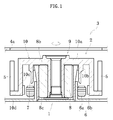
- FIG. 1 is a schematic sectional view for illustrating a fan motor 2 comprising a fluid-dynamic bearing device 1 according to the present invention, and an information apparatus 3 having the fan motor 2 mounted therein.
- the fan motor 2 is a fan motor 2 of what is called a centrifugal type, and is mounted to a base 4 of a component to be cooled (information apparatus 3).
- the fan motor 2 comprises the fluid-dynamic bearing device 1, a plurality of fans (blades) 5 mounted to a rotary member 9 of the fluid-dynamic bearing device 1, and a drive portion 6 configured to rotate the fans 5 integrally with the rotary member 9.
- the drive portion 6 comprises coils 6a and magnets 6b opposed to each other across a radial gap.
- the coils 6a are fixed to a stationary side (base 4), and the magnets 6b are fixed to a rotary side (hub portion 10 of the rotary member 9).
- FIG. 2 is a sectional view for illustrating the fluid-dynamic bearing device 1 built in the fan motor 2.
- the fluid-dynamic bearing device 1 mainly comprises a housing 7, a sintered metal bearing 8 fixed to an inner periphery of the housing 7, and the rotary member 9 to be rotated relative to the sintered metal bearing 8.
- the rotary member 9 comprises the hub portion 10 arranged on an upper-end opening side of the housing 7, and a shaft portion 11 inserted along an inner periphery of the sintered metal bearing 8.
- the hub portion 10 comprises a disc portion 10a covering the upper-end opening side of the housing 7, a first cylindrical portion 10b extending from the disc portion 10a to the axially lower side, a second cylindrical portion 10c located on the radially outer side with respect to the first cylindrical portion 10b and extending from the disc portion 10a to the axially lower side, and a flange portion 10d further extending from an axially lower end of the second cylindrical portion 10c to the radially outer side.
- the disc portion 10a is opposed to one end surface (upper end surface 8b) of the sintered metal bearing 8 fixed to the inner periphery of the housing 7.
- the plurality of fans 5 are formed integrally with the hub portion 10 in an upright posture along an outer rim of the flange portion 10d.
- the shaft portion 11 is formed integrally with the hub portion 10, and a flange portion 12 is arranged separately at a lower end thereof.
- an upper end surface 12a of the flange portion 12 is opposed to another end surface (lower end surface 8c) of the sintered metal bearing 8.
- the shaft portion 11 and the hub portion 10 may be formed separately from each other. In that case, by methods such as press-fitting and bonding, an upper end of the shaft portion 11 may be fixed to a hole formed at a center of the hub portion 10.
- one of the shaft portion 11 and the hub portion 10 to be made of materials different from each other may be formed through injection molding of a metal or a resin with another one of the shaft portion 11 and the hub portion 10 being used as an insert component.
- the housing 7 is formed into a cylindrical shape opened at both axial ends thereof, and a lower-end opening side thereof is sealed by a lid member 13. Further, the housing 7 has an inner peripheral surface 7a fixed to the sintered metal bearing 8, and an outer peripheral surface 7b fixed to the base 4 of the information apparatus 3.
- An axial opposing clearance between an upper end surface 7c of the housing 7 and a lower end surface 10a1 of the disc portion 10a of the hub portion 10 is larger than an opposing clearance between the upper end surface 8b of the sintered metal bearing 8 and the lower end surface 10a1 of the disc portion 10a.
- the opposing clearances are set so as to have sizes that do not substantially have influence on increase in torque loss during rotational drive.
- a tapered sealing surface 7d increased in outer diameter dimension as approaching to the upper side is formed on an upper side of an outer periphery of the housing 7.
- An annular sealing space S gradually reduced in radial dimension from a closed side (lower side) toward an opening side (upper side) of the housing 7 is formed between the tapered sealing surface 7d and an inner peripheral surface 10b1 of the first cylindrical portion 10b.
- the sealing space S is communicated to a radially outer side of a thrust bearing gap in a first thrust bearing portion T1 described later, thereby allowing a lubricating oil to flow in a bearing interior space comprising other bearing gaps.
- a charging amount of the lubricating oil is adjusted so that an oil surface (gas-liquid interface) of the lubricating oil is constantly maintained within the sealing space S under a state in which the lubricating oil is filled in the bearing interior space (refer to FIG. 2 ).
- the sintered metal bearing 8 is formed of a porous body of a sintered metal obtained through compression molding and sintering of raw-material powder containing, as main components, metals such as copper (comprising not only pure copper but also copper alloys) and iron (comprising not only pure iron but also iron alloys such as stainless steel).
- the sinteredmetal bearing 8 is formed into a cylindrical shape.
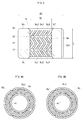
- an array region of a plurality of dynamic pressure generating grooves 8a1 is formed as a dynamic pressure generating portion. According to this embodiment, as illustrated in FIG.
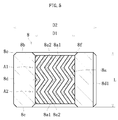
- the plurality of dynamic pressure generating grooves 8a1 inclined at a predetermined angle with respect to a circumferential direction, inclined ridge portions 8a2 partitioning those dynamic pressure generating grooves 8a1 from each other in the circumferential direction, and belt portions 8a3 extending in the circumferential direction and partitioning the dynamic pressure generating grooves 8a1 from each other in the axial direction are arrayed in a herringbone pattern (both of the inclined ridge portions 8a2 and the belt portions 8a3 are indicated by cross-hatching in FIG. 3 ).
- Two dynamic pressure generating groove array regions are formed continuously to each other in the axial direction.
- both an upper dynamic pressure generating groove array region A1 and a lower dynamic pressure generating groove array region A2 are formed so as to be axially symmetrical with respect to an axial center line (imaginary line connecting axial centers of the belt portion 8a3 to each other in the circumferential direction), and are equal to each other in axial dimension.
- an array region of a plurality of dynamic pressure generating grooves 8b1 is formed as a dynamic pressure generating portion.
- an orientation of the spiral of the dynamic pressure generating grooves 8b1 is set to an orientation corresponding to a rotation direction of the rotary member 9.
- an array region of a plurality of dynamic pressure generating grooves 8c1 is formed as a dynamic pressure generating portion.
- an orientation of the spiral of the dynamic pressure generating grooves 8c1 is set to the orientation corresponding to the rotation direction of the rotary member 9.
- the orientation of the spiral of the dynamic pressure generating grooves 8c1 is set to an orientation corresponding to a rotation direction of the flange portion 12 of the rotary member 9 (orientation that allows a dynamic pressure to be generated between the lower end surface 8c and the flange portion 12).
- a thrust bearing gap of a second thrust bearing portion T2 described later is formed between the dynamic pressure generating groove array region configured as described above and the opposed upper end surface 12a of the flange portion 12 (refer to FIG. 2 ).
- the thrust bearing gaps are automatically formed at a time point when the fluid-dynamic bearing device 1 is assembled. Specifically, under a state in which the fluid-dynamic bearing device 1 is assembled as illustrated in FIG. 2 , the flange portion 12 and the disc portion 10a of the hub portion 10 are arranged at positions of axially sandwiching the sintered metal bearing 8 fixed to the housing 7. Thus, a sum of both the thrust bearing gaps is set equal to a value obtained through subtraction of an axial dimension of the sintered metal bearing 8 from an opposing clearance between the lower end surface 10a1 of the hub portion 10 and the upper end surface 12a of the flange portion 12.
- one or a plurality of axial grooves 8d1 are formed in an outer peripheral surface 8d of the sintered metal bearing 8. Under a state in which the sintered metal bearing 8 is fixed to the housing 7, passages for a lubricating oil are formed between the axial grooves 8d1 and the inner peripheral surface 7a of the housing 7 (refer to FIG. 2 ).
- An axial dimension L thereof (axial separation clearance between both the end surfaces 8b and 8c) is set to 6 mm or less.
- An inner diameter dimension D1 (strictly, inner diameter dimension of each of the belt portions 8a3 that are smallest diameter portions as well as the inclined ridge portions 8a2 on the inner peripheral surface 8a) is set to 3 mm or less, and an outer diameter dimension D2 is set to 6 mm or less.
- an overall bearing density ratio (obtained through division of a density of the porous body of the sintered metal bearing 8 by a density on a premise that the porous body has no pores) is set to 80% or more and 95% or less. Further, in the sintered metal bearing 8, fluctuation of the density ratio in the bearing is suppressed (equalized) in comparison with those in the related art. Specifically, it is preferred that the fluctuation of the density ratio in the bearing be set to 3% or less. Note that, the fluctuation of the density ratio in this case can be evaluated with a microporosity that has a certain correlation with the density ratio. Specifically, the microporosity is represented in ratio (percentage) of a volume of micropores per unit volume of the bearing, and empirically has a negative correlation with the density ratio (correlation coefficient of -1).
- a surface porosity of the inner peripheral surface 8a specifically, surface porosities of inner peripheral surfaces of the inclined ridge portions 8a2 and the belt portions 8a3, which serve as a radial bearing surface, are adjusted to, for example, 2% or more and 15% or less.
- the sintered metal bearing 8 configured as described above is manufactured, for example, by the following steps.
- a method for producing the sintered metal bearing 8 configured as described above mainly comprises a compacting step (S1) of molding raw-material powder through compression into a molded green compact, a sintering step (S2) of sintering the molded green compact into a sintered compact, and a dynamic pressure generating groove sizing step (S3) of sizing the sintered compact and molding the dynamic pressure generating grooves 8a1 as the dynamic pressure generating portion at least in the inner peripheral surface 8a of the sintered compact.
- the method for producing the sinteredmetal bearing 8 further comprises a dimension sizing step (S031) of performing dimension sizing on the sintered compact, and a rotary sizing step (S032) of performing rotary sizing on the inner peripheral surface 8a of the sintered compact. Description of the steps (S1) to (S3) is made with a focus on the dynamic pressure generating groove sizing step (S3).
- the raw-material powder is prepared as a material for the sintered metal bearing 8 to be finished into a complete product, and then is compressed into a predetermined shape through die press molding.
- the compression molding of the raw-material powder is performed by using a molding die set comprising a die, a core pin to be inserted and arranged into a hole of the die, a lower punch arranged between the die and the core pin, and configured to be capable of being raised and lowered relative to the die, and an upper punch configured to be capable of being displaced (raised and lowered) relative to both the die and the lower punch.
- the raw-material powder is charged into a space defined by an inner peripheral surface of the die, an outer peripheral surface of the core pin, and an upper end surface of the lower punch. Then, under a state in which the lower punch is fixed, the upper punch is lowered so that the charged raw-material powder is pressurized in the axial direction. Next, under the pressurized state, the upper punch is lowered to a predetermined position so that the raw-material powder is compressed into a predetermined axial dimension. In this way, the molded green compact is obtained.
- the axial dimension of the molded green compact can be set within an appropriate range by adjusting a distance between the lower end surface of the upper punch and the upper end surface of the lower punch, more specifically, a bottom dead center of the upper punch in accordance with a target axial dimension (which is set in consideration of dimensional changes as a result of the subsequent sintering and various sizing).
- this molded green compact is sintered at a temperature appropriate to the raw-material powder. With this, a sintered compact is obtained.
- the dimension sizing is performed on the sintered compact so that an outer diameter dimension, an inner diameter dimension, and an axial dimension of the sintered compact are corrected into dimensions in accordance with those of a complete product.
- the surface porosity of the inner peripheral surface 8a is adjusted to a ratio appropriate to a fluid-dynamic bearing.
- the predetermined dynamic pressure generating groove array regions A1 and A2 have not yet been formed in the inner peripheral surface 8a of the sintered compact.
- the array regions of the predetermined dynamic pressure generating grooves 8b1 and 8c1 have not yet been formed in both the end surfaces 8b and 8c of the sintered compact.
- a molding apparatus used in this case comprises a die having a press-fit hole for the sintered compact, a sizing pin arranged so as to be insertable into the press-fit hole of the die, a lower punch arranged between the die and the sizing pin, and configured to be capable of being raised and lowered relative to the die, and an upper punch configured to be capable of being raised and lowered relative to both the die and the lower punch.
- an inner diameter dimension of the press-fit hole of the die is appropriately set in accordance with a press-fitting margin of the sintered compact to be subjected to the sizing. Further, on an outer peripheral surface of the sizing pin, there is formed a molding die in conformity with the patterns of the dynamic pressure generating groove array regions A1 and A2 ( FIG. 3 ) on the inner peripheral surface 8a to be molded.
- molding dies On a lower end surface of the upper punch and an upper end surface of the lower punch, there are respectively formed molding dies in conformity with the patterns of the array region of the dynamic pressure generating grooves 8b1 of the upper end surface 8b to be molded, and the array region of the dynamic pressure generating grooves 8c1 of the lower end surface 8c to be molded ( FIG. 4A and FIG. 4B ) .
- the sintered compact is arranged on the upper end surface of the die, and in this state, the upper punch and the sizing pin are lowered from above. With this, the sizing pin is inserted along an inner periphery of the sintered compact so that the molding die formed in advance on the outer periphery of the sizing pin is radially opposed to an inner peripheral surface of the sintered compact. Then, when the molding die reaches a predetermined axial position on the inner peripheral surface, the upper punch and the sizing pin are further lowered so that an upper end surface of the sintered compact is pressed.
- the sintered compact is pressed into the press-fit hole of the die so that an outer peripheral surface of the sintered compact is compressed, and the molding die of the sizing pin inserted along the inner periphery in advance is caused to bite into the inner peripheral surface of the sintered compact. Further, in this state, the upper punch is further lowered so that the sintered compact is sandwiched between the upper punch and the lower punch, thereby axially compressing the sintered compact under a state in which radially outward deformation thereof is restricted by the die. With this, the molding die is caused to further bite into the inner peripheral surface.
- the pattern of the molding die is transferred onto the inner peripheral surface of the sintered compact so that the dynamic pressure generating groove array regions A1 and A2 are molded on the inner peripheral surface. Further, at this time, the molding dies formed on the lower end surface of the upper punch and the upper end surface of the lower punch are caused to bite respectively into the upper end surface and the lower end surface of the sintered compact. With this, the patterns of the molding dies are transferred onto the upper end surface and the lower end surfaces. In this way, the array regions of the dynamic pressure generating grooves 8b1 and 8c1 are correspondingly molded.
- the die is lowered relative to the lower punch so that the sintered compact is released from the restriction by the die. With this, the sintered compact is caused to spring back radially outward. As a result, the sintered compact can be removed from the sizing pin. An amount of the spring-back required at this time is set so that the molding die formed around the sizing pin is not caught in the axial direction on the inner peripheral surface (specifically, dynamic pressure generating groove array regions) of the sintered compact after the sizing.
- a thickness of the sintered compact that is, a thickness of the sintered metal bearing 8 as a complete product (obtained through subtraction of the inner diameter dimension D1 from the outer diameter dimension D2) is set in consideration of a groove depth (several micrometers) of the dynamic pressure generating grooves 8a1 to be molded.
- the inner diameter dimension D1 is set to 3 mm or less
- the outer diameter dimension D2 is set to 6 mm or less.
- the lubricating oil is filled as a lubricating fluid.
- lubricating oils of various types maybe used. Specifically, an ester-based lubricating oil that has a low evaporation rate and is not liable to be reduced in viscosity at low temperature, and a fluorinated lubricating oil that is higher in resistance (for degradation) than the ester-based lubricating oil are suitably used.
- the lubricating oil to be used have, for example, a kinematic viscosity of 20 cSt or more and 170 cSt or less at a temperature of 40°C, and a kinematic viscosity of 2 cSt or more and 50 cSt or less at a temperature of 100°C.
- the regions on the inner peripheral surface 8a of the sintered metal bearing 8 are opposed to an outer peripheral surface of the shaft portion 11 across a radial bearing gap. Then, along with the rotation of the shaft portion 11, the lubricating oil in the radial bearing gap is forced toward an axial center in each of the dynamic pressure generating groove array regions A1 and A2. With this, a pressure of the lubricating oil is increased in a region on an axial center side (belt portion 8a3 in this case).
- a first radial bearing portion R1 and a second radial bearing portion R2 configured to radially support the shaft portion 11 in a freely rotatable and non-contact manner are formed separately from each other in the axial direction.
- an oil film of the lubricating oil is formed by a dynamic pressure action of the dynamic pressure generating grooves 8b1.
- an oil film of the lubricating oil is formed by a dynamic pressure action of the dynamic pressure generating grooves 8c1.
- the axial dimension of the sintered metal bearing 8 is set to 6 mm or less, and the overall bearing density ratio is set within the range of 80% or more and 95% or less.
- differences in density ratio between a surface layer portion side and a core portion side and between the upper side and the lower side in the axial direction can be significantly reduced.
- the lubricating oil is allowed to moderately flow between the inside of the sintered metal bearing 8 and the bearing gaps via the dynamic pressure generating groove array regions A1 and A2 (specifically, bottom surfaces of the dynamic pressure generating grooves 8a1).
- a density ratio of the surface layer portion of the sintered metal bearing 8 can be set to such a level that the lubricating oil and the like can be caused to appropriately seep into the bearing gaps while preventing release of a dynamic pressure from a surface of the bearing.
- a density ratio in a region excluding the surface layer portion can be set so that the inner region is impregnated with an appropriate amount of the lubricating oil and the like.
- the lubricating oil to be impregnated into the bearing interior space comprising internal pores of the sintered metal bearing 8 the lubricating oil having the kinematic viscosity of 20 cSt or more and 170 cSt or less at the temperature of 40°C, and the kinematic viscosity of 2 cSt or more and 50 cSt or less at the temperature of 100°C is used.
- the density ratio of the sinteredmetal bearing 8 is adjusted so that an internal structure thereof is optimized, and the viscosity of the lubricating oil to be used is set relatively high in accordance with usage. With this, bearing performance can be further enhanced, and deterioration of the lubricating oil can be suppressed.
- the fluid-dynamic bearing device 1 excellent in performance and reliability can be provided.
- the sintered metal bearing 8 and a method of manufacturing the sintered metal bearing 8 according to the present invention are not limited to those in the above description of the embodiment of the present invention. As a matter of course, various modifications and changes may be made thereto within the scope of the present invention.
- the dynamic pressure generating groove array regions A1 and A2 are molded on the inner peripheral surface of the sintered compact through the dynamic pressure generating groove sizing step involving press-fitting the sintered compact into the die, and axially compressing the sintered compact with the upper punch and the lower punch.
- the dynamic pressure generating groove array regions A1 and A2 may be formed on the inner peripheral surface of the sintered compact only through axial press-fitting without performing the press-fitting into the die.
- how the upper punch and the lower punch are moved at the time of the axial compression is not limited to that exemplified in the embodiment described above.
- there maybe employed other pressing methods Specifically, under the state in which the sintered compact is axially compressed to some extent between the lowered upper punch and the lower punch, the lower punch may be raised so that the sintered compact is further compressed.
- the dynamic pressure generating groove array regions A1 and A2 each having the herringbone pattern are formed as the dynamic pressure generating portions on the inner peripheral surface 8a.
- the belt portion 8a3 may be omitted from each of the dynamic pressure generating groove array regions A1 and A2 so that the dynamic pressure generating grooves 8a1 and the inclined ridge portions 8a2 arranged on the upper side and the lower side with respect to the belt portion 8a3 are connected to each other.
- each of the dynamic pressure generating groove array regions A1 and A2 may be or need not necessarily be symmetrical with respect to an axial center position. Still further, the patterns in the dynamic pressure generating groove array regions A1 andA2 continuous to each other in the axial direction may be or need not necessarily be symmetrical to each other with respect to a boundary therebetween. In other words, each of the dynamic pressure generating groove array regions A1 and A2 may be formed into any pattern as long as the dynamic pressure generating grooves are arrayed in an orientation of causing the lubricating oil to be drawn to the axial center side therein.
- each of the dynamic pressure generating groove array regions A1 and A2 may be formed into any pattern as long as the lubricating oil is drawn away from a position of the boundary between the dynamic pressure generating groove array regions A1 and A2 toward the end surfaces 8b and 8c.
- the dynamic pressure generating grooves 8b1 and 8c1 are formed respectively in the upper end surface 8b and the lower end surface 8c.
- the dynamic pressure generating grooves may be molded only in one of the upper end surface 8b and the lower end surface 8c, or need not be formed in both of the end surfaces 8b and 8c.
- the sintered metal bearing 8 may be impregnated with the lubricating oil at a time point of completion of the bearing (time point before incorporation).
- the sintered metal bearing 8 described above is applicable not only to the fluid-dynamic bearing device 1 of a thin type as exemplified above (type in which the sealing space S is arranged on the radially outer side with respect to the radial bearing portions R1 and R2), but also to fluid-dynamic bearing devices of other types.
- the fluid-dynamic bearing device 1 is applicable not only to the fan motor 2 of the centrifugal type as exemplified above, but also to fan motors 2 of other types such as an axial-flow type.
- the fluid-dynamic bearing device 1 may be suitably used not only as bearing devices to be used for driving the fan motors 2, but also as bearing devices to be used for driving various motors comprising a polygon scanner motor for laser beam printers, and a small motor for the information apparatus 3, which is used in high-speed rotation, such as a spindle motor to be used in disk drives such as an HDD, and a spindle motor to be used for driving magneto-optical discs or optical discs.
Landscapes
- Engineering & Computer Science (AREA)
- General Engineering & Computer Science (AREA)
- Mechanical Engineering (AREA)
- Chemical & Material Sciences (AREA)
- Oil, Petroleum & Natural Gas (AREA)
- Physics & Mathematics (AREA)
- Fluid Mechanics (AREA)
- Metallurgy (AREA)
- Sliding-Contact Bearings (AREA)
- Connection Of Motors, Electrical Generators, Mechanical Devices, And The Like (AREA)
Abstract
Description
- The present invention relates to a sintered metal bearing , a fluid-dynamic bearing device comprising the sintered metal bearing, and a fan motor comprising the fluid-dynamic bearing device.
- A sintered metal bearing is used under a state in which a lubricating oil is impregnated into inner pores thereof. The lubricating oil impregnated into the sintered metal bearing seeps into a sliding portion with respect to a shaft, which is inserted along an inner periphery of the sintered metal bearing, along with relative rotation of the shaft, to thereby form an oil film. The sintered metal bearing is configured to rotationally support the shaft through this oil film. Such a sintered metal bearing has excellent rotational accuracy and quietness, and hence has been suitably used as a bearing device for a motor to be mounted to various electrical apparatus such as information apparatus. Specifically, the sintered metal bearing has been suitably used in a spindle motor for an HDD or a disk drive for a CD, a DVD, and a Blu-ray disc, a polygon scanner motor for a laser beam printer (LBP), or a fan motor.
- As an example of sintered metal bearings of this type, there has been known a sintered metal bearing in which, in order to achieve further improvement in quietness and prolongation of life, dynamic pressure generating grooves serving as a dynamic pressure generating portion are arrayed in a predetermined pattern on an inner peripheral surface and/or an end surface of the bearing. As a method of molding the dynamic pressure generating grooves in this case, there has been proposed what is called dynamic pressure generating groove sizing. In this sizing, for example, a sintered compact is press-fitted to an inner periphery of a die, and is compressed in an axial direction by upper and lower punches so that a molding die on an outer periphery of a sizing pin that is inserted in advance along an inner periphery of the sintered compact is caused to bite into the sintered compact. With this, a pattern of the molding die, specifically, a pattern corresponding to the dynamic pressure generating grooves is transferred onto an inner peripheral surface of the sintered compact. In this way, the dynamic pressure generating grooves are molded into a predetermined pattern (refer, for example, to Patent Literature 1).
- As an example of the array pattern of the above-mentioned dynamic pressure generating grooves, array regions of a plurality of the dynamic pressure generating grooves may be formed at two positions on the inner peripheral surface of the bearing separately from each other in the axial direction. In those array regions of the dynamic pressure generating grooves, the dynamic pressure generating grooves are arrayed in an orientation of causing a lubricating oil to be drawn to an axial center in each of the array regions of the dynamic pressure generating grooves. In view of this, there has been proposed a fluid-dynamic bearing in which, in order to prevent generation of a negative pressure between the array regions, a recessed portion (large diameter portion on the bearing side or small diameter portion on the shaft side) is formed in the inner peripheral surface or an opposed outer peripheral surface of a shaft as a lubricating oil reservoir (refer, for example, to Patent Literature 2).
-
- Patent Literature 1:
JP 3607492 B2 - Patent Literature 2:
JP 4006810 B2 - Incidentally, in recent years, along with downsizing and thinning of information apparatus, there have been demands for downsizing of various motors to be built in the information apparatus. For example, cooling fan motors to be used, for example, in notebook computers have been thinned, and hence the thinning of bearing devices to be used in those motors has also been required. Meanwhile, required cooling performance is equivalent to those in the related art. Thus, for example, an impeller (fan) needs to be upsized in accordance therewith. However, as a result of upsizing the fan, a rotator is increased in weight. Thus, a load to be applied to the bearing is undesirably increased. As a countermeasure against the increase in load, it is appropriate to enhance bearing rigidity. Specifically, a method of increasing a length (longitudinal dimension) of the dynamic pressure generating grooves is conceivable.
- However, in the sintered metal bearing including the dynamic pressure generating groove array regions formed at two positions on the inner peripheral surface as described in
Patent Literature 2, the dynamic pressure generating grooves are difficult to increase in length. This is because an attempt to increase the length of the dynamic pressure generating grooves is incompatible with demands for thinning of not only the motor but also the fluid-dynamic bearing device to be built therein, that is, there is a tendency that the sintered metal bearing as a whole is reduced in axial dimension. When the length of the dynamic pressure generating grooves is increased contrary to this tendency, an axial dimension of a region between the array regions (for example, recessed portion formed in the inner peripheral surface of the bearing as the lubricating oil reservoir) is inevitably reduced. Thus, a volume of the lubricating oil to be retained in the recessed portion is also reduced. As a result, when the negative pressure is generated in this region, bubbles are generated and enter bearing gaps, which causes risks of deterioration in bearing performance and reduction in buffer volume of the lubricating oil when the bubbles are expanded. - In view of the circumstances described above, the present invention has been made to achieve a technical object of providing a sintered metal bearing, a fluid-dynamic bearing device comprising the sintered metal bearing, and a fan motor comprising the fluid-dynamic bearing device, each of which is capable of preventing generation of a negative pressure in a bearing interior space and exerting necessary and sufficient bearing rigidity while downsizing a fluid-dynamic bearing device.
- The above-mentioned object is achieved by a sintered metal bearing according to one embodiment of the present invention. That is, this sintered metal bearing has a feature in a sintered metal bearing that is formed of a porous body formed through sintering of a compact obtained through compression molding of raw-material powder, the sintered metal bearing comprising a dynamic pressure generating portion formed on an inner peripheral surface of the sintered metal bearing, wherein the dynamic pressure generating portion comprises dynamic pressure generating groove array regions formed continuously to each other in an axial direction of the sintered metal bearing, the dynamic pressure generating groove array regions each comprising a plurality of dynamic pressure generating grooves arrayed so as to be inclined with respect to a circumferential direction of the sintered metal bearing, wherein an axial dimension of the sintered metal bearing is set to 6 mm or less, and wherein a density ratio of the overall sintered metal bearing is set to 80% or more and 95% or less. Note that, the "density ratio" herein refers to a value (percentage) obtained through division of a density of the porous body of the sintered metal bearing by a density on a premise that the porous body has no pores.
- The present invention has been made based on a finding that the density ratio is equalized in comparison with those in the related art in the case where the axial dimension of the sintered metal bearing is set to 6 mm or less and the overall bearing density ratio is set within the range of 80% or more and 95% or less. Specifically, in a general compacting step for bearings of this type, the raw-material powder filled in a molding die is molded into a predetermined shape (normally, cylindrical shape) through pressurization along an axial direction of a green compact to be molded. Thus, when the raw-material powder is molded through compression into an axial dimension of more than 6 mm as in the related art, the density is likely to be high on a directly pressurized side (for example, upper side in the axial direction) or a surface layer portion to be held in direct contact with the molding die, and is likely to be low on a side far away from the pressurized side or the molding die (for example, lower side in the axial direction or core portion of the molded green compact). Meanwhile, in the one embodiment of the present invention, the axial dimension is reduced to 6 mm or less, and the density ratio therein is set to 80% or more and 95% or less (through, for example, adjustment of a compression amount of the raw-material powder in the axial direction). As a result, it has been found that differences in density ratio between the surface layer side and the core side and between one side and another side in the axial direction are significantly reduced. Thus, also when the dynamic pressure generating groove array regions are formed continuously to each other in the axial direction and the recessed portion as described, for example, in
Patent Literature 2 is omitted, a lubricating fluid is allowed to moderately flow between an inside of the bearing and bearing gaps via a bearing surface (dynamic pressure generating groove array regions). Thus, also when a lubricating fluid reservoir (recessed portion) is not formed, a risk of generation of a negative pressure in a region between the dynamic pressure generating groove array regions can be reduced as much as possible, and dynamic pressure actions can be sufficiently exerted. With this, a high bearing rigidity can be achieved. Further, as a result of the omission of the region between the dynamic pressure generating groove array regions, depending on the axial dimension, the dynamic pressure generating grooves can be formed to be longer than those in the related art. Thus, the dynamic pressure actions can be further sufficiently exerted. - Further, in the sintered metal bearing according to the one embodiment of the present invention, fluctuation of the density ratio in the sintered metal bearing may be set to 3% or less. By limiting the fluctuation of the density ratio in the bearing within this range while setting the overall bearing density ratio within the above-mentioned range, the density ratio of the surface layer portion can be set to such a level that the lubricating oil and the like can be caused to appropriately seep into the bearing gaps while preventing release of a dynamic pressure from a surface of the bearing. Further, the density ratio in the region excluding the surface layer portion (inner region with respect to the surface layer portion) can be set so that the inner region is impregnated with an appropriate amount of the lubricating oil and the like.
- Further, in the sintered metal bearing according to the one embodiment of the present invention, each of the dynamic pressure generating groove array regions continuous to each other in the axial direction may have a herringbone pattern, and the plurality of dynamic pressure generating grooves of the each of the dynamic pressure generating groove array regions may be continuous to each other at a center side of the each of the dynamic pressure generating groove array regions in the axial direction.
- Further, in the sintered metal bearing according to the one embodiment of the present invention, an inner diameter dimension of the sintered metal bearing may be set to 3 mm or less, and an outer diameter dimension of the sintered metal bearing may be set to 6 mm or less. In the one embodiment of the present invention, a measure for securing the bearing rigidity can be taken by adjusting the axial dimension and the density ratio. Thus, a radial dimension can be maintained at a level equivalent to those in the related art. Specifically, when the inner diameter dimension and the outer diameter dimension are set so as to fall within those ranges, spring-back can be caused by an appropriate amount in the radial direction. Thus, the dynamic pressure generating grooves can be molded so as to have a predetermined depth (at level of several micrometers), and hence necessary dynamic pressure actions can be expected.
- The sintered metal bearing described above may be suitably provided as, for example, a fluid-dynamic bearing device, comprising: this sintered metal bearing; a shaft portion inserted along an inner periphery of the sintered metal bearing; a sealing space formed between a stationary side comprising the sintered metal bearing and a rotary side comprising the shaft portion; and a lubricating oil filled in a bearing interior space comprising an inside of the sintered metal bearing.
- Further, in this case, in the fluid-dynamic bearing device according to the one embodiment of the present invention, the lubricating oil may have: a kinematic viscosity of 20 cSt or more and 170 cSt or less at a temperature of 40°C; and a kinematic viscosity of 2 cSt or more and 50 cSt or less at a temperature of 100°C. In this way, the density ratio of the sintered metal bearing is adjusted so that an internal structure thereof is optimized, and the viscosity of the lubricating oil to be used is set relatively high in accordance with usage. With this, bearing performance can be further enhanced, and deterioration of the lubricating oil can be suppressed. Thus, also when thinning is achieved, the fluid-dynamic bearing device excellent in performance and reliability can be provided.
- Further, the fluid-dynamic bearing device described above is capable of exerting appropriate and stable bearing rigidity over a long time period even when a rotator is increased in weight. Thus, a fan motor comprising the fluid-dynamic bearing device described above and a fan mounted to the shaft portion can also be suitably provided.
- As described above, according to the one embodiment of the present invention, it is possible to provide the sintered metal bearing, a fluid-dynamic bearing device comprising the sintered metal bearing, and a fan motor comprising the fluid-dynamic bearing device, each of which is capable of preventing generation of a negative pressure in the bearing interior space and exerting necessary and sufficient bearing rigidity while downsizing the fluid-dynamic bearing device.
-
-
FIG. 1 is a schematic view for illustrating a fan motor according to an embodiment of the present invention. -
FIG. 2 is a sectional view for illustrating a fluid-dynamic bearing device constructing the motor ofFIG. 1 . -
FIG. 3 is a sectional view for illustrating a sintered metal bearing according to the embodiment of the present invention. -
FIG. 4A is a view for illustrating an upper end surface of the sintered metal bearing illustrated inFIG. 3 as viewed from an upper side in an axial direction. -
FIG. 4B is a view for illustrating a lower end surface of the sintered metal bearing illustrated inFIG. 3 as viewed from a lower side in the axial direction. -
FIG. 5 is a sectional view for illustrating a sintered metal bearing according to another embodiment of the present invention. - Now, description is made of an embodiment of the present invention with reference to the drawings. Note that, in the following description, with respect to a sintered metal bearing, a disc portion side of a hub portion is referred to as "upper side," and a lid member side is referred to as "lower side." As a matter of course, where and how actual products are set or used are not limited by those upper and lower directions.
-
FIG. 1 is a schematic sectional view for illustrating afan motor 2 comprising a fluid-dynamic bearing device 1 according to the present invention, and aninformation apparatus 3 having thefan motor 2 mounted therein. Thefan motor 2 is afan motor 2 of what is called a centrifugal type, and is mounted to a base 4 of a component to be cooled (information apparatus 3). - The
fan motor 2 comprises the fluid-dynamic bearing device 1, a plurality of fans (blades) 5 mounted to arotary member 9 of the fluid-dynamic bearing device 1, and adrive portion 6 configured to rotate thefans 5 integrally with therotary member 9. Thedrive portion 6 comprisescoils 6a andmagnets 6b opposed to each other across a radial gap. In this embodiment, thecoils 6a are fixed to a stationary side (base 4), and themagnets 6b are fixed to a rotary side (hub portion 10 of the rotary member 9). - Through energization of the
coils 6a, an excitation force is generated between thecoils 6a and themagnets 6b so that themagnets 6b are rotated. With this, the plurality offans 5 arranged upright along an outer rim of the rotary member 9 (in this embodiment, hub portion 10) are rotated integrally with therotary member 9. This rotation causes thefans 5 to generate air flow to a radially outer side. In a manner of being drawn by the air flow through aport 4a of the base 4 arranged on an axially upper side with respect to thefan motor 2, intake air flow is generated toward an axially lower side. With the air flow generated in theinformation apparatus 3 in this manner, heat generated in theinformation apparatus 3 can be dissipated to an outside (cooling can be performed). -
FIG. 2 is a sectional view for illustrating the fluid-dynamic bearing device 1 built in thefan motor 2. The fluid-dynamic bearing device 1 mainly comprises ahousing 7, asintered metal bearing 8 fixed to an inner periphery of thehousing 7, and therotary member 9 to be rotated relative to thesintered metal bearing 8. - The
rotary member 9 comprises thehub portion 10 arranged on an upper-end opening side of thehousing 7, and ashaft portion 11 inserted along an inner periphery of thesintered metal bearing 8. - The
hub portion 10 comprises adisc portion 10a covering the upper-end opening side of thehousing 7, a firstcylindrical portion 10b extending from thedisc portion 10a to the axially lower side, a secondcylindrical portion 10c located on the radially outer side with respect to the firstcylindrical portion 10b and extending from thedisc portion 10a to the axially lower side, and aflange portion 10d further extending from an axially lower end of the secondcylindrical portion 10c to the radially outer side. Thedisc portion 10a is opposed to one end surface (upper end surface 8b) of thesintered metal bearing 8 fixed to the inner periphery of thehousing 7. Further, the plurality offans 5 are formed integrally with thehub portion 10 in an upright posture along an outer rim of theflange portion 10d. - In this embodiment, the
shaft portion 11 is formed integrally with thehub portion 10, and aflange portion 12 is arranged separately at a lower end thereof. In this case, anupper end surface 12a of theflange portion 12 is opposed to another end surface (lower end surface 8c) of thesintered metal bearing 8. As a matter of course, theshaft portion 11 and thehub portion 10 may be formed separately from each other. In that case, by methods such as press-fitting and bonding, an upper end of theshaft portion 11 may be fixed to a hole formed at a center of thehub portion 10. Alternatively, one of theshaft portion 11 and thehub portion 10 to be made of materials different from each other may be formed through injection molding of a metal or a resin with another one of theshaft portion 11 and thehub portion 10 being used as an insert component. - The
housing 7 is formed into a cylindrical shape opened at both axial ends thereof, and a lower-end opening side thereof is sealed by alid member 13. Further, thehousing 7 has an innerperipheral surface 7a fixed to thesintered metal bearing 8, and an outerperipheral surface 7b fixed to the base 4 of theinformation apparatus 3. An axial opposing clearance between anupper end surface 7c of thehousing 7 and a lower end surface 10a1 of thedisc portion 10a of thehub portion 10 is larger than an opposing clearance between theupper end surface 8b of thesintered metal bearing 8 and the lower end surface 10a1 of thedisc portion 10a. In this embodiment, the opposing clearances are set so as to have sizes that do not substantially have influence on increase in torque loss during rotational drive. - A
tapered sealing surface 7d increased in outer diameter dimension as approaching to the upper side is formed on an upper side of an outer periphery of thehousing 7. An annular sealing space S gradually reduced in radial dimension from a closed side (lower side) toward an opening side (upper side) of thehousing 7 is formed between thetapered sealing surface 7d and an inner peripheral surface 10b1 of the firstcylindrical portion 10b. During rotation of theshaft portion 11 and thehub portion 10, the sealing space S is communicated to a radially outer side of a thrust bearing gap in a first thrust bearing portion T1 described later, thereby allowing a lubricating oil to flow in a bearing interior space comprising other bearing gaps. Further, a charging amount of the lubricating oil is adjusted so that an oil surface (gas-liquid interface) of the lubricating oil is constantly maintained within the sealing space S under a state in which the lubricating oil is filled in the bearing interior space (refer toFIG. 2 ). - The
sintered metal bearing 8 is formed of a porous body of a sintered metal obtained through compression molding and sintering of raw-material powder containing, as main components, metals such as copper (comprising not only pure copper but also copper alloys) and iron (comprising not only pure iron but also iron alloys such as stainless steel). In general, thesinteredmetal bearing 8 is formed into a cylindrical shape. In a part or an entirety of an innerperipheral surface 8a of thesintered metal bearing 8, an array region of a plurality of dynamic pressure generating grooves 8a1 is formed as a dynamic pressure generating portion. According to this embodiment, as illustrated inFIG. 3 , in the dynamic pressure generating groove array region, the plurality of dynamic pressure generating grooves 8a1 inclined at a predetermined angle with respect to a circumferential direction, inclined ridge portions 8a2 partitioning those dynamic pressure generating grooves 8a1 from each other in the circumferential direction, and belt portions 8a3 extending in the circumferential direction and partitioning the dynamic pressure generating grooves 8a1 from each other in the axial direction are arrayed in a herringbone pattern (both of the inclined ridge portions 8a2 and the belt portions 8a3 are indicated by cross-hatching inFIG. 3 ). Two dynamic pressure generating groove array regions are formed continuously to each other in the axial direction. In this case, both an upper dynamic pressure generating groove array region A1 and a lower dynamic pressure generating groove array region A2 are formed so as to be axially symmetrical with respect to an axial center line (imaginary line connecting axial centers of the belt portion 8a3 to each other in the circumferential direction), and are equal to each other in axial dimension. - In a part or an entirety of the
upper end surface 8b of thesintered metal bearing 8, an array region of a plurality of dynamic pressure generating grooves 8b1 is formed as a dynamic pressure generating portion. In this embodiment, for example, as illustrated inFIG. 4A , there is formed a region in which the plurality of dynamic pressure generating grooves 8b1 extending in a spiral pattern are arrayed in the circumferential direction. In this case, an orientation of the spiral of the dynamic pressure generating grooves 8b1 is set to an orientation corresponding to a rotation direction of therotary member 9. Under a state in which the fluid-dynamic bearing device 1 illustrated inFIG. 2 is driven to rotate, the thrust bearing gap of the first thrust bearing portion T1 described later is formed between the dynamic pressure generating groove array region configured as described above and the opposed lower end surface 10a1 of thedisc portion 10a of thehub portion 10. - Further, in a part or an entirety of the
lower end surface 8c of thesintered metal bearing 8, an array region of a plurality of dynamic pressure generating grooves 8c1 is formed as a dynamic pressure generating portion. In this embodiment, for example, as illustrated inFIG. 4B , there is formed a region in which the plurality of dynamic pressure generating grooves 8c1 extending in a spiral pattern are arrayed in the circumferential direction. In this case, an orientation of the spiral of the dynamic pressure generating grooves 8c1 is set to the orientation corresponding to the rotation direction of therotary member 9. Specifically, in a setting example illustrated inFIG. 2 , the orientation of the spiral of the dynamic pressure generating grooves 8c1 is set to an orientation corresponding to a rotation direction of theflange portion 12 of the rotary member 9 (orientation that allows a dynamic pressure to be generated between thelower end surface 8c and the flange portion 12). Thus, under the state in which the fluid-dynamicbearing device 1 illustrated inFIG. 2 is driven to rotate, a thrust bearing gap of a second thrust bearing portion T2 described later is formed between the dynamic pressure generating groove array region configured as described above and the opposedupper end surface 12a of the flange portion 12 (refer toFIG. 2 ). - The thrust bearing gaps are automatically formed at a time point when the fluid-
dynamic bearing device 1 is assembled. Specifically, under a state in which the fluid-dynamic bearing device 1 is assembled as illustrated inFIG. 2 , theflange portion 12 and thedisc portion 10a of thehub portion 10 are arranged at positions of axially sandwiching thesintered metal bearing 8 fixed to thehousing 7. Thus, a sum of both the thrust bearing gaps is set equal to a value obtained through subtraction of an axial dimension of thesintered metal bearing 8 from an opposing clearance between the lower end surface 10a1 of thehub portion 10 and theupper end surface 12a of theflange portion 12. - In an outer
peripheral surface 8d of thesintered metal bearing 8, one or a plurality of axial grooves 8d1 (three in this embodiment) are formed. Under a state in which the sinteredmetal bearing 8 is fixed to thehousing 7, passages for a lubricating oil are formed between the axial grooves 8d1 and the innerperipheral surface 7a of the housing 7 (refer toFIG. 2 ). - Next, description is made of various dimensions of the
sintered metal bearing 8. An axial dimension L thereof (axial separation clearance between both the end surfaces 8b and 8c) is set to 6 mm or less. An inner diameter dimension D1 (strictly, inner diameter dimension of each of the belt portions 8a3 that are smallest diameter portions as well as the inclined ridge portions 8a2 on the innerperipheral surface 8a) is set to 3 mm or less, and an outer diameter dimension D2 is set to 6 mm or less. - Next, description is made of a density ratio of the
sinteredmetal bearing 8. In thesinteredmetal bearing 8, an overall bearing density ratio (obtained through division of a density of the porous body of thesintered metal bearing 8 by a density on a premise that the porous body has no pores) is set to 80% or more and 95% or less. Further, in thesintered metal bearing 8, fluctuation of the density ratio in the bearing is suppressed (equalized) in comparison with those in the related art. Specifically, it is preferred that the fluctuation of the density ratio in the bearing be set to 3% or less. Note that, the fluctuation of the density ratio in this case can be evaluated with a microporosity that has a certain correlation with the density ratio. Specifically, the microporosity is represented in ratio (percentage) of a volume of micropores per unit volume of the bearing, and empirically has a negative correlation with the density ratio (correlation coefficient of -1). - Further, a surface porosity of the inner
peripheral surface 8a, specifically, surface porosities of inner peripheral surfaces of the inclined ridge portions 8a2 and the belt portions 8a3, which serve as a radial bearing surface, are adjusted to, for example, 2% or more and 15% or less. - The
sintered metal bearing 8 configured as described above is manufactured, for example, by the following steps. - Specifically, a method for producing the
sintered metal bearing 8 configured as described above mainly comprises a compacting step (S1) of molding raw-material powder through compression into a molded green compact, a sintering step (S2) of sintering the molded green compact into a sintered compact, and a dynamic pressure generating groove sizing step (S3) of sizing the sintered compact and molding the dynamic pressure generating grooves 8a1 as the dynamic pressure generating portion at least in the innerperipheral surface 8a of the sintered compact. In this embodiment, as steps after the sintering step (S2) and before the dynamic pressure generating groove sizing step (S3), the method for producing thesinteredmetal bearing 8 further comprises a dimension sizing step (S031) of performing dimension sizing on the sintered compact, and a rotary sizing step (S032) of performing rotary sizing on the innerperipheral surface 8a of the sintered compact. Description of the steps (S1) to (S3) is made with a focus on the dynamic pressure generating groove sizing step (S3). - First, the raw-material powder is prepared as a material for the
sintered metal bearing 8 to be finished into a complete product, and then is compressed into a predetermined shape through die press molding. Specifically, although not shown, the compression molding of the raw-material powder is performed by using a molding die set comprising a die, a core pin to be inserted and arranged into a hole of the die, a lower punch arranged between the die and the core pin, and configured to be capable of being raised and lowered relative to the die, and an upper punch configured to be capable of being displaced (raised and lowered) relative to both the die and the lower punch. In this case, the raw-material powder is charged into a space defined by an inner peripheral surface of the die, an outer peripheral surface of the core pin, and an upper end surface of the lower punch. Then, under a state in which the lower punch is fixed, the upper punch is lowered so that the charged raw-material powder is pressurized in the axial direction. Next, under the pressurized state, the upper punch is lowered to a predetermined position so that the raw-material powder is compressed into a predetermined axial dimension. In this way, the molded green compact is obtained. In this case, the axial dimension of the molded green compact can be set within an appropriate range by adjusting a distance between the lower end surface of the upper punch and the upper end surface of the lower punch, more specifically, a bottom dead center of the upper punch in accordance with a target axial dimension (which is set in consideration of dimensional changes as a result of the subsequent sintering and various sizing). - After the molded green compact is obtained as described above, this molded green compact is sintered at a temperature appropriate to the raw-material powder. With this, a sintered compact is obtained.
- Then, the dimension sizing is performed on the sintered compact so that an outer diameter dimension, an inner diameter dimension, and an axial dimension of the sintered compact are corrected into dimensions in accordance with those of a complete product. In addition, the surface porosity of the inner
peripheral surface 8a is adjusted to a ratio appropriate to a fluid-dynamic bearing. At this stage, the predetermined dynamic pressure generating groove array regions A1 and A2 have not yet been formed in the innerperipheral surface 8a of the sintered compact. Similarly, although not shown, the array regions of the predetermined dynamic pressure generating grooves 8b1 and 8c1 have not yet been formed in both the end surfaces 8b and 8c of the sintered compact. - Through predetermined dynamic pressure generating groove sizing on the sintered compact that is obtained through the series of steps described above, the dynamic pressure generating groove array regions A1 and A2 are molded in the inner
peripheral surface 8a of the sintered compact. Although not shown, a molding apparatus used in this case comprises a die having a press-fit hole for the sintered compact, a sizing pin arranged so as to be insertable into the press-fit hole of the die, a lower punch arranged between the die and the sizing pin, and configured to be capable of being raised and lowered relative to the die, and an upper punch configured to be capable of being raised and lowered relative to both the die and the lower punch. In this case, an inner diameter dimension of the press-fit hole of the die is appropriately set in accordance with a press-fitting margin of the sintered compact to be subjected to the sizing. Further, on an outer peripheral surface of the sizing pin, there is formed a molding die in conformity with the patterns of the dynamic pressure generating groove array regions A1 and A2 (FIG. 3 ) on the innerperipheral surface 8a to be molded. On a lower end surface of the upper punch and an upper end surface of the lower punch, there are respectively formed molding dies in conformity with the patterns of the array region of the dynamic pressure generating grooves 8b1 of theupper end surface 8b to be molded, and the array region of the dynamic pressure generating grooves 8c1 of thelower end surface 8c to be molded (FIG. 4A and FIG. 4B ) . - Next, description is made of an example of the dynamic pressure generating groove sizing using the molding apparatus described above. First, the sintered compact is arranged on the upper end surface of the die, and in this state, the upper punch and the sizing pin are lowered from above. With this, the sizing pin is inserted along an inner periphery of the sintered compact so that the molding die formed in advance on the outer periphery of the sizing pin is radially opposed to an inner peripheral surface of the sintered compact. Then, when the molding die reaches a predetermined axial position on the inner peripheral surface, the upper punch and the sizing pin are further lowered so that an upper end surface of the sintered compact is pressed. With this, the sintered compact is pressed into the press-fit hole of the die so that an outer peripheral surface of the sintered compact is compressed, and the molding die of the sizing pin inserted along the inner periphery in advance is caused to bite into the inner peripheral surface of the sintered compact. Further, in this state, the upper punch is further lowered so that the sintered compact is sandwiched between the upper punch and the lower punch, thereby axially compressing the sintered compact under a state in which radially outward deformation thereof is restricted by the die. With this, the molding die is caused to further bite into the inner peripheral surface. In this way, the pattern of the molding die is transferred onto the inner peripheral surface of the sintered compact so that the dynamic pressure generating groove array regions A1 and A2 are molded on the inner peripheral surface. Further, at this time, the molding dies formed on the lower end surface of the upper punch and the upper end surface of the lower punch are caused to bite respectively into the upper end surface and the lower end surface of the sintered compact. With this, the patterns of the molding dies are transferred onto the upper end surface and the lower end surfaces. In this way, the array regions of the dynamic pressure generating grooves 8b1 and 8c1 are correspondingly molded.
- After the predetermined dynamic pressure generating groove array regions A1 and A2 and the predetermined array regions of the dynamic pressure generating grooves 8b1 and 8c1 are molded respectively in the inner peripheral surface and both the end surfaces of the sintered compact in this way, the die is lowered relative to the lower punch so that the sintered compact is released from the restriction by the die. With this, the sintered compact is caused to spring back radially outward. As a result, the sintered compact can be removed from the sizing pin. An amount of the spring-back required at this time is set so that the molding die formed around the sizing pin is not caught in the axial direction on the inner peripheral surface (specifically, dynamic pressure generating groove array regions) of the sintered compact after the sizing. Thus, a thickness of the sintered compact, that is, a thickness of the
sintered metal bearing 8 as a complete product (obtained through subtraction of the inner diameter dimension D1 from the outer diameter dimension D2) is set in consideration of a groove depth (several micrometers) of the dynamic pressure generating grooves 8a1 to be molded. In this embodiment, the inner diameter dimension D1 is set to 3 mm or less, and the outer diameter dimension D2 is set to 6 mm or less. With this, the dynamic pressure generating grooves 8a1 can be molded so as to have a necessary depth, and the sizing pin used for the molding can be smoothly withdrawn from the sintered compact after the sizing. - In the fluid-
dynamic bearing device 1 configured as described above (in bearing interior space), the lubricating oil is filled as a lubricating fluid. Note that, lubricating oils of various types maybe used. Specifically, an ester-based lubricating oil that has a low evaporation rate and is not liable to be reduced in viscosity at low temperature, and a fluorinated lubricating oil that is higher in resistance (for degradation) than the ester-based lubricating oil are suitably used. Further, from a viewpoint of a kinematic viscosity, it is preferred that the lubricating oil to be used have, for example, a kinematic viscosity of 20 cSt or more and 170 cSt or less at a temperature of 40°C, and a kinematic viscosity of 2 cSt or more and 50 cSt or less at a temperature of 100°C. - In the fluid-
dynamic bearing device 1 configured as described above, during the rotation of the shaft portion 11 (rotary member 9), the regions on the innerperipheral surface 8a of the sintered metal bearing 8 (two upper and lower dynamic pressure generating groove array regions A1 and A2), which serve as the radial bearing surface, are opposed to an outer peripheral surface of theshaft portion 11 across a radial bearing gap. Then, along with the rotation of theshaft portion 11, the lubricating oil in the radial bearing gap is forced toward an axial center in each of the dynamic pressure generating groove array regions A1 and A2. With this, a pressure of the lubricating oil is increased in a region on an axial center side (belt portion 8a3 in this case). By such a dynamic pressure action of the dynamic pressure generating grooves 8a1, a first radial bearing portion R1 and a second radial bearing portion R2 configured to radially support theshaft portion 11 in a freely rotatable and non-contact manner are formed separately from each other in the axial direction. - Further, in the thrust bearing gap between the
upper end surface 8b of the sintered metal bearing 8 (array region of the dynamic pressure generating grooves 8b1) and the opposed lower end surface 10a1 of thehub portion 10, an oil film of the lubricating oil is formed by a dynamic pressure action of the dynamic pressure generating grooves 8b1. Further, in the thrust bearing gap between thelower end surface 8c of the sintered metal bearing 8 (array region of the dynamic pressure generating grooves 8c1) and the opposedupper end surface 12a of theflange portion 12, an oil film of the lubricating oil is formed by a dynamic pressure action of the dynamic pressure generating grooves 8c1. Then, by pressures of those oil films, the first thrust bearing portion T1 and the second thrust bearing portion T2 configured to support therotary member 9 in a non-contact manner in both thrust directions are formed. - In this way, in the present invention, the axial dimension of the
sintered metal bearing 8 is set to 6 mm or less, and the overall bearing density ratio is set within the range of 80% or more and 95% or less. Thus, differences in density ratio between a surface layer portion side and a core portion side and between the upper side and the lower side in the axial direction can be significantly reduced. With this, also when the dynamic pressure generating groove array regions A1 and A2 are formed continuously to each other in the axial direction, the lubricating oil is allowed to moderately flow between the inside of thesintered metal bearing 8 and the bearing gaps via the dynamic pressure generating groove array regions A1 and A2 (specifically, bottom surfaces of the dynamic pressure generating grooves 8a1). Thus, also when a lubricating fluid reservoir (recessed portion) as inPatent Literature 2 is not formed, a risk of generation of a negative pressure in a region between the dynamic pressure generating groove array regions A1 and A2 can be reduced as much as possible, and the dynamic pressure actions can be sufficiently exerted. With this, a high bearing rigidity can be achieved. - Further, in this case, by adjusting sizes and molding conditions so that the fluctuation of the density ratio in the
sintered metal bearing 8 is suppressed to 3% or less, a density ratio of the surface layer portion of thesintered metal bearing 8 can be set to such a level that the lubricating oil and the like can be caused to appropriately seep into the bearing gaps while preventing release of a dynamic pressure from a surface of the bearing. Further, a density ratio in a region excluding the surface layer portion (inner region on the core portion side with respect to the surface layer portion) can be set so that the inner region is impregnated with an appropriate amount of the lubricating oil and the like. With this, the sealing space S can be designed in consideration of a buffering function to be exerted in accordance with temperature change. - Further, in this embodiment, as the lubricating oil to be impregnated into the bearing interior space comprising internal pores of the
sintered metal bearing 8, the lubricating oil having the kinematic viscosity of 20 cSt or more and 170 cSt or less at the temperature of 40°C, and the kinematic viscosity of 2 cSt or more and 50 cSt or less at the temperature of 100°C is used. In this way, the density ratio of thesinteredmetal bearing 8 is adjusted so that an internal structure thereof is optimized, and the viscosity of the lubricating oil to be used is set relatively high in accordance with usage. With this, bearing performance can be further enhanced, and deterioration of the lubricating oil can be suppressed. Thus, also when thinning is achieved, the fluid-dynamic bearing device 1 excellent in performance and reliability can be provided. - The
sintered metal bearing 8 and a method of manufacturing the sinteredmetal bearing 8 according to the present invention are not limited to those in the above description of the embodiment of the present invention. As a matter of course, various modifications and changes may be made thereto within the scope of the present invention. - For example, in the case exemplified in the embodiment described above, the dynamic pressure generating groove array regions A1 and A2 are molded on the inner peripheral surface of the sintered compact through the dynamic pressure generating groove sizing step involving press-fitting the sintered compact into the die, and axially compressing the sintered compact with the upper punch and the lower punch. When possible, the dynamic pressure generating groove array regions A1 and A2 may be formed on the inner peripheral surface of the sintered compact only through axial press-fitting without performing the press-fitting into the die. Further, how the upper punch and the lower punch are moved at the time of the axial compression is not limited to that exemplified in the embodiment described above. For example, there maybe employed other pressing methods. Specifically, under the state in which the sintered compact is axially compressed to some extent between the lowered upper punch and the lower punch, the lower punch may be raised so that the sintered compact is further compressed.
- Further, in the case exemplified in the embodiment described above, the dynamic pressure generating groove array regions A1 and A2 each having the herringbone pattern are formed as the dynamic pressure generating portions on the inner
peripheral surface 8a. As a matter of course, there may be formed dynamic pressure generating groove array regions in other patterns. Specifically, as illustrated inFIG. 5 , in each of the dynamic pressure generating groove array regions A1 and A2, there may be employed a configuration in which the belt portion 8a3 may be omitted from each of the dynamic pressure generating groove array regions A1 and A2 so that the dynamic pressure generating grooves 8a1 and the inclined ridge portions 8a2 arranged on the upper side and the lower side with respect to the belt portion 8a3 are connected to each other. Further, the pattern in each of the dynamic pressure generating groove array regions A1 and A2 may be or need not necessarily be symmetrical with respect to an axial center position. Still further, the patterns in the dynamic pressure generating groove array regions A1 andA2 continuous to each other in the axial direction may be or need not necessarily be symmetrical to each other with respect to a boundary therebetween. In other words, each of the dynamic pressure generating groove array regions A1 and A2 may be formed into any pattern as long as the dynamic pressure generating grooves are arrayed in an orientation of causing the lubricating oil to be drawn to the axial center side therein. More specifically, each of the dynamic pressure generating groove array regions A1 and A2 may be formed into any pattern as long as the lubricating oil is drawn away from a position of the boundary between the dynamic pressure generating groove array regions A1 and A2 toward the end surfaces 8b and 8c. - Still further, in the case exemplified in the embodiment described above, the dynamic pressure generating grooves 8b1 and 8c1 are formed respectively in the
upper end surface 8b and thelower end surface 8c. However, the dynamic pressure generating grooves may be molded only in one of theupper end surface 8b and thelower end surface 8c, or need not be formed in both of the end surfaces 8b and 8c. - Yet further, in the method exemplified in the embodiment described above, not only the bearing interior space but also the internal pores of the
sintered metal bearing 8 are impregnated with the lubricating oil after thesintered metal bearing 8 is fixed to the housing 7 (after the fluid-dynamic bearing device 1 is assembled). As a matter of course, thesintered metal bearing 8 may be impregnated with the lubricating oil at a time point of completion of the bearing (time point before incorporation). - Further, as a matter of course, the
sintered metal bearing 8 described above is applicable not only to the fluid-dynamic bearing device 1 of a thin type as exemplified above (type in which the sealing space S is arranged on the radially outer side with respect to the radial bearing portions R1 and R2), but also to fluid-dynamic bearing devices of other types. - Still further, the fluid-
dynamic bearing device 1 according to the present invention is applicable not only to thefan motor 2 of the centrifugal type as exemplified above, but also tofan motors 2 of other types such as an axial-flow type. As a matter of course, the fluid-dynamic bearing device 1 may be suitably used not only as bearing devices to be used for driving thefan motors 2, but also as bearing devices to be used for driving various motors comprising a polygon scanner motor for laser beam printers, and a small motor for theinformation apparatus 3, which is used in high-speed rotation, such as a spindle motor to be used in disk drives such as an HDD, and a spindle motor to be used for driving magneto-optical discs or optical discs. -
- 1
- fluid-dynamic bearing device
- 2
- fan motor
- 3
- information apparatus
- 4
- base
- 5
- fan
- 6
- drive portion
- 7
- housing
- 7a
- inner peripheral surface
- 8
- sintered metal bearing
- 8a
- inner peripheral surface
- 8a1
- dynamic pressure generating groove (inner peripheral surf ace)
- 8a2
- inclined ridge portion
- 8a3
- belt portion
- 8b
- upper end surface
- 8b1
- dynamic pressure generating groove (upper end surface)
- 8c
- lower end surface
- 8c1
- dynamic pressure generating groove (lower end surface)
- 9
- rotary member
- 10
- hub portion
- 10a
- disc portion
- 10a1
- lower end surface
- 12
- flange portion
- 13
- lid member
- A1, A2
- dynamic pressure generating groove array region
- R1, R2
- radial bearing portion
- T1, T2
- thrust bearing portion
- S
- sealing space
Claims (7)
- A sintered metal bearing that is formed of a porous body formed through sintering of a compact obtained through compression molding of raw-material powder, the sintered metal bearing comprising a dynamic pressure generating portion formed on an inner peripheral surface of the sintered metal bearing,
wherein the dynamic pressure generating portion comprises dynamic pressure generating groove array regions formed continuously to each other in an axial direction of the sintered metal bearing, the dynamic pressure generating groove array regions each comprising a plurality of dynamic pressure generating grooves arrayed so as to be inclined with respect to a circumferential direction of the sintered metal bearing,
wherein an axial dimension of the sintered metal bearing is set to 6 mm or less, and
wherein a density ratio of the sintered metal bearing is set to 80% or more and 95% or less. - The sintered metal bearing according to claim 1, wherein fluctuation of the density ratio in the sintered metal bearing is set to 3% or less.
- The sintered metal bearing according to claim 1,
wherein each of the dynamic pressure generating groove array regions continuous to each other in the axial direction has a herringbone pattern, and
wherein the plurality of dynamic pressure generating grooves of the each of the dynamic pressure generating groove array regions are continuous to each other at a center side of the each of the dynamic pressure generating groove array regions in the axial direction. - The sintered metal bearing according to claim 1,
wherein an inner diameter dimension of the sintered metal bearing is set to 3 mm or less, and
wherein an outer diameter dimension of the sintered metal bearing is set to 6 mm or less. - A fluid-dynamic bearing device, comprising:the sintered metal bearing of any one of claims 1 to 4;a shaft portion inserted along an inner periphery of the sintered metal bearing;a sealing space formed between a stationary side comprising the sintered metal bearing and a rotary side comprising the shaft portion; anda lubricating oil filled in a bearing interior space comprising an inside of the sintered metal bearing.
- The fluid-dynamic bearing device according to claim 5, wherein the lubricating oil has:a kinematic viscosity of 20 cSt or more and 170 cSt or less at a temperature of 40°C; anda kinematic viscosity of 2 cSt or more and 50 cSt or less at a temperature of 100°C.
- A fan motor, comprising:the fluid-dynamic bearing device of claim 5 or 6; anda fan mounted to the shaft portion.
Applications Claiming Priority (2)
| Application Number | Priority Date | Filing Date | Title |
|---|---|---|---|
| JP2013196973A JP6199675B2 (en) | 2013-09-24 | 2013-09-24 | Sintered metal bearing and fluid dynamic pressure bearing device provided with the bearing |
| PCT/JP2014/073554 WO2015045813A1 (en) | 2013-09-24 | 2014-09-05 | Sintered metal bearing and fluid-dynamic bearing device provided with said bearing |
Publications (3)
| Publication Number | Publication Date |
|---|---|
| EP3051156A1 true EP3051156A1 (en) | 2016-08-03 |
| EP3051156A4 EP3051156A4 (en) | 2017-07-05 |
| EP3051156B1 EP3051156B1 (en) | 2020-04-22 |
Family
ID=52742960
Family Applications (1)
| Application Number | Title | Priority Date | Filing Date |
|---|---|---|---|
| EP14849434.7A Active EP3051156B1 (en) | 2013-09-24 | 2014-09-05 | Sintered metal bearing, fluid-dynamic bearing device provided with said bearing, and fan motor provided with said bearing device |
Country Status (6)
| Country | Link |
|---|---|
| US (1) | US10415573B2 (en) |
| EP (1) | EP3051156B1 (en) |
| JP (1) | JP6199675B2 (en) |
| KR (1) | KR102206759B1 (en) |
| CN (1) | CN105579720B (en) |
| WO (1) | WO2015045813A1 (en) |
Families Citing this family (13)
| Publication number | Priority date | Publication date | Assignee | Title |
|---|---|---|---|---|
| JP2018061408A (en) * | 2016-10-07 | 2018-04-12 | 日本電産株式会社 | Fan motor |
| US20180298911A1 (en) * | 2017-04-17 | 2018-10-18 | Hao Lee | Shaft structures of fan |
| CN108869541B (en) * | 2018-01-12 | 2024-04-02 | 刘慕华 | Radial bearing, rotor system and control method of radial bearing |
| US20190353177A1 (en) * | 2018-05-21 | 2019-11-21 | Asia Vital Components Co., Ltd. | Fan frame seat and fan thereof |
| JP7320365B2 (en) * | 2019-03-28 | 2023-08-03 | Ntn株式会社 | Sintered metal connecting rod and manufacturing method thereof |
| FR3116876B1 (en) | 2019-12-19 | 2024-10-11 | Eaton Intelligent Power Ltd | Self-correcting hydrodynamic seal |
| US11209047B1 (en) * | 2020-07-14 | 2021-12-28 | John Wun-Chang Shih | Liquid guiding structure for fluid dynamic pressure bearing |
| JP7759178B2 (en) | 2020-09-28 | 2025-10-23 | Ntn株式会社 | Dynamic pressure bearing, fluid dynamic pressure bearing device, and motor |
| JP7560389B2 (en) | 2021-03-12 | 2024-10-02 | Ntn株式会社 | Oil-impregnated sintered bearing and fluid dynamic bearing device equipped with said bearing |
| JP7720210B2 (en) * | 2021-09-27 | 2025-08-07 | Ntn株式会社 | Dynamic pressure bearing and fluid dynamic pressure bearing device equipped with same |
| JP7649012B2 (en) * | 2022-06-14 | 2025-03-19 | Ntn株式会社 | Lubricating oil composition for fluid dynamic bearings, fluid dynamic bearings, and fluid dynamic bearing devices |
| WO2023243496A1 (en) * | 2022-06-14 | 2023-12-21 | Ntn株式会社 | Fluid dynamic pressure bearing lubricant oil composition, fluid dynamic pressure bearing, and fluid dynamic pressure bearing apparatus |
| JP2024043207A (en) * | 2022-09-16 | 2024-03-29 | Ntn株式会社 | Dynamic pressure bearing, dynamic pressure bearing device and motor |
Family Cites Families (19)
| Publication number | Priority date | Publication date | Assignee | Title |
|---|---|---|---|---|
| JPS5873611A (en) | 1981-10-24 | 1983-05-02 | Tadao Sasaki | Laying method of waterway with penstock |
| JPS607492A (en) | 1983-06-27 | 1985-01-16 | 富士通株式会社 | Monosyllable voice recognition system |
| JPS636810A (en) | 1986-06-26 | 1988-01-12 | Toshiba Corp | Manufacture of superconducting coil |
| GB2322915B (en) | 1997-03-06 | 2001-06-06 | Ntn Toyo Bearing Co Ltd | Hydrodynamic type porous oil-impregnated bearing |
| JP3607492B2 (en) | 1997-03-06 | 2005-01-05 | Ntn株式会社 | Dynamic pressure type porous oil-impregnated bearing and manufacturing method thereof |
| JP4006810B2 (en) | 1998-02-27 | 2007-11-14 | 松下電器産業株式会社 | Electric motor and heat sink device using the same |
| JP2002097503A (en) * | 2000-07-17 | 2002-04-02 | Hitachi Powdered Metals Co Ltd | Method of manufacturing sintered bearing with dynamic pressure groove |
| JP2006046540A (en) * | 2004-08-05 | 2006-02-16 | Matsushita Electric Ind Co Ltd | Hydrodynamic bearing device |
| JP2006105237A (en) * | 2004-10-04 | 2006-04-20 | Nippon Densan Corp | Fluid dynamic pressure bearing, spindle motor provided with the fluid dynamic pressure bearing, and recording disc drive provided with the spindle motor |
| JP4573349B2 (en) * | 2004-10-21 | 2010-11-04 | 日立粉末冶金株式会社 | Manufacturing method of hydrodynamic bearing |
| JP4790586B2 (en) * | 2006-01-10 | 2011-10-12 | Ntn株式会社 | Hydrodynamic bearing device and manufacturing method thereof |
| CN101400904B (en) * | 2006-01-10 | 2011-07-06 | Ntn株式会社 | Fluid dynamic pressure bearing device and method of producing the same |
| JP2007231966A (en) * | 2006-02-27 | 2007-09-13 | Hitachi Powdered Metals Co Ltd | Sintered hydrodynamic bearing manufacturing method |
| TW200835864A (en) * | 2007-02-27 | 2008-09-01 | Jian-Dih Jeng | Simplified fluid dynamic bearing design |
| JP5092516B2 (en) * | 2007-04-17 | 2012-12-05 | Nokクリューバー株式会社 | Lubricating oil composition |
| JP2010053914A (en) | 2008-08-27 | 2010-03-11 | Panasonic Corp | Hydrodynamic bearing device, spindle motor, and information device |
| JP5394182B2 (en) * | 2009-09-29 | 2014-01-22 | Ntn株式会社 | Fluid dynamic bearing device and manufacturing method thereof |
| US20120014629A1 (en) * | 2010-07-16 | 2012-01-19 | Samsung Electro-Mechanics Co., Ltd | Porous hydrodynamic bearing |
| JP5674495B2 (en) * | 2011-01-31 | 2015-02-25 | Ntn株式会社 | Fluid dynamic bearing device |
-
2013
- 2013-09-24 JP JP2013196973A patent/JP6199675B2/en active Active
-
2014
- 2014-09-05 CN CN201480052728.7A patent/CN105579720B/en active Active
- 2014-09-05 US US15/021,771 patent/US10415573B2/en active Active
- 2014-09-05 WO PCT/JP2014/073554 patent/WO2015045813A1/en not_active Ceased
- 2014-09-05 EP EP14849434.7A patent/EP3051156B1/en active Active
- 2014-09-05 KR KR1020167005646A patent/KR102206759B1/en active Active
Also Published As
| Publication number | Publication date |
|---|---|
| WO2015045813A1 (en) | 2015-04-02 |
| KR102206759B1 (en) | 2021-01-25 |
| CN105579720B (en) | 2019-01-22 |
| JP2015064019A (en) | 2015-04-09 |
| US20160230769A1 (en) | 2016-08-11 |
| EP3051156A4 (en) | 2017-07-05 |
| CN105579720A (en) | 2016-05-11 |
| EP3051156B1 (en) | 2020-04-22 |
| US10415573B2 (en) | 2019-09-17 |
| JP6199675B2 (en) | 2017-09-20 |
| KR20160058765A (en) | 2016-05-25 |
Similar Documents
| Publication | Publication Date | Title |
|---|---|---|
| EP3051156B1 (en) | Sintered metal bearing, fluid-dynamic bearing device provided with said bearing, and fan motor provided with said bearing device | |
| US8876385B2 (en) | Bearing member and fluid dynamic bearing device using same | |
| WO2009104441A1 (en) | Sintered bearing | |
| EP3051159B1 (en) | Sintered metal bearing and method for producing same | |
| US10167899B2 (en) | Sintered bearing, fluid dynamic bearing device provided with same, and sintered bearing manufacturing method | |
| US12442414B2 (en) | Oil-impregnated sintered bearing and fluid dynamic bearing device provided with the bearing | |
| CN117940681A (en) | Dynamic pressure bearing and fluid dynamic pressure bearing device provided with same | |
| JP2011047005A (en) | Method of manufacturing bearing sleeve and fluid dynamic bearing device | |
| JP7713302B2 (en) | Fluid dynamic bearing device | |
| JP4172944B2 (en) | Hydrodynamic bearing device and manufacturing method thereof | |
| JP7076266B2 (en) | Manufacturing method of sintered oil-impregnated bearing | |
| JP7840187B2 (en) | Sintered oil-impregnated bearing and fluid dynamic bearing device equipped with this bearing | |
| JP5606831B2 (en) | Bearing member and manufacturing method thereof | |
| JP2008111520A (en) | Dynamic pressure bearing device | |
| JP2008281107A (en) | Forming method of dynamic pressure generating part | |
| JP2007100803A (en) | Method for manufacturing oil impregnated sintered bearing, and sizing pin to be used for the method | |
| JP2019157918A (en) | Sintered metal-made dynamic pressure bearing | |
| JP2006105331A (en) | Bearing sleeve and its manufacturing method | |
| JP2007315485A (en) | Method for manufacturing dynamic pressure bearing device | |
| JP2008164023A (en) | Manufacturing method of hydrodynamic-pressure bearing device |
Legal Events
| Date | Code | Title | Description |
|---|---|---|---|
| PUAI | Public reference made under article 153(3) epc to a published international application that has entered the european phase |
Free format text: ORIGINAL CODE: 0009012 |
|
| 17P | Request for examination filed |
Effective date: 20160421 |
|
| AK | Designated contracting states |
Kind code of ref document: A1 Designated state(s): AL AT BE BG CH CY CZ DE DK EE ES FI FR GB GR HR HU IE IS IT LI LT LU LV MC MK MT NL NO PL PT RO RS SE SI SK SM TR |
|
| AX | Request for extension of the european patent |
Extension state: BA ME |
|
| DAX | Request for extension of the european patent (deleted) | ||
| A4 | Supplementary search report drawn up and despatched |
Effective date: 20170607 |
|
| RIC1 | Information provided on ipc code assigned before grant |
Ipc: F16C 33/12 20060101ALI20170531BHEP Ipc: H02K 7/14 20060101ALI20170531BHEP Ipc: F16C 17/10 20060101AFI20170531BHEP Ipc: G11B 19/20 20060101ALI20170531BHEP Ipc: F16C 33/10 20060101ALI20170531BHEP Ipc: F16C 33/14 20060101ALI20170531BHEP |
|
| RIC1 | Information provided on ipc code assigned before grant |
Ipc: H02K 7/14 20060101ALN20190628BHEP Ipc: F04D 29/057 20060101ALN20190628BHEP Ipc: F16C 33/12 20060101ALI20190628BHEP Ipc: F16C 33/10 20060101ALI20190628BHEP Ipc: F04D 25/06 20060101ALN20190628BHEP Ipc: F16C 33/14 20060101ALI20190628BHEP Ipc: F16C 17/10 20060101AFI20190628BHEP |
|
| RIC1 | Information provided on ipc code assigned before grant |
Ipc: F16C 33/10 20060101ALI20190718BHEP Ipc: F16C 33/12 20060101ALI20190718BHEP Ipc: F16C 17/10 20060101AFI20190718BHEP Ipc: F16C 33/14 20060101ALI20190718BHEP Ipc: F04D 29/057 20060101ALN20190718BHEP Ipc: F04D 25/06 20060101ALN20190718BHEP Ipc: H02K 7/14 20060101ALN20190718BHEP |
|
| REG | Reference to a national code |
Ref country code: DE Ref legal event code: R079 Ref document number: 602014064274 Country of ref document: DE Free format text: PREVIOUS MAIN CLASS: F16C0033100000 Ipc: F16C0017100000 |
|
| RIC1 | Information provided on ipc code assigned before grant |
Ipc: F04D 25/06 20060101ALN20190821BHEP Ipc: F16C 33/14 20060101ALI20190821BHEP Ipc: F16C 17/10 20060101AFI20190821BHEP Ipc: F16C 33/12 20060101ALI20190821BHEP Ipc: F04D 29/057 20060101ALN20190821BHEP Ipc: F16C 33/10 20060101ALI20190821BHEP Ipc: H02K 7/14 20060101ALN20190821BHEP |
|
| RIC1 | Information provided on ipc code assigned before grant |
Ipc: F04D 29/057 20060101ALN20190924BHEP Ipc: F16C 33/10 20060101ALI20190924BHEP Ipc: H02K 7/14 20060101ALN20190924BHEP Ipc: F16C 33/12 20060101ALI20190924BHEP Ipc: F16C 33/14 20060101ALI20190924BHEP Ipc: F16C 17/10 20060101AFI20190924BHEP Ipc: F04D 25/06 20060101ALN20190924BHEP |
|
| GRAP | Despatch of communication of intention to grant a patent |
Free format text: ORIGINAL CODE: EPIDOSNIGR1 |
|
| STAA | Information on the status of an ep patent application or granted ep patent |
Free format text: STATUS: GRANT OF PATENT IS INTENDED |
|
| INTG | Intention to grant announced |
Effective date: 20191114 |
|
| GRAS | Grant fee paid |
Free format text: ORIGINAL CODE: EPIDOSNIGR3 |
|
| GRAA | (expected) grant |
Free format text: ORIGINAL CODE: 0009210 |
|
| STAA | Information on the status of an ep patent application or granted ep patent |
Free format text: STATUS: THE PATENT HAS BEEN GRANTED |
|
| AK | Designated contracting states |
Kind code of ref document: B1 Designated state(s): AL AT BE BG CH CY CZ DE DK EE ES FI FR GB GR HR HU IE IS IT LI LT LU LV MC MK MT NL NO PL PT RO RS SE SI SK SM TR |
|
| REG | Reference to a national code |
Ref country code: CH Ref legal event code: EP |
|
| REG | Reference to a national code |
Ref country code: IE Ref legal event code: FG4D |
|
| REG | Reference to a national code |
Ref country code: DE Ref legal event code: R096 Ref document number: 602014064274 Country of ref document: DE |
|
| REG | Reference to a national code |
Ref country code: AT Ref legal event code: REF Ref document number: 1260500 Country of ref document: AT Kind code of ref document: T Effective date: 20200515 |
|
| REG | Reference to a national code |
Ref country code: LT Ref legal event code: MG4D |
|
| REG | Reference to a national code |
Ref country code: NL Ref legal event code: MP Effective date: 20200422 |
|
| PG25 | Lapsed in a contracting state [announced via postgrant information from national office to epo] |
Ref country code: SE Free format text: LAPSE BECAUSE OF FAILURE TO SUBMIT A TRANSLATION OF THE DESCRIPTION OR TO PAY THE FEE WITHIN THE PRESCRIBED TIME-LIMIT Effective date: 20200422 Ref country code: NO Free format text: LAPSE BECAUSE OF FAILURE TO SUBMIT A TRANSLATION OF THE DESCRIPTION OR TO PAY THE FEE WITHIN THE PRESCRIBED TIME-LIMIT Effective date: 20200722 Ref country code: IS Free format text: LAPSE BECAUSE OF FAILURE TO SUBMIT A TRANSLATION OF THE DESCRIPTION OR TO PAY THE FEE WITHIN THE PRESCRIBED TIME-LIMIT Effective date: 20200822 Ref country code: GR Free format text: LAPSE BECAUSE OF FAILURE TO SUBMIT A TRANSLATION OF THE DESCRIPTION OR TO PAY THE FEE WITHIN THE PRESCRIBED TIME-LIMIT Effective date: 20200723 Ref country code: FI Free format text: LAPSE BECAUSE OF FAILURE TO SUBMIT A TRANSLATION OF THE DESCRIPTION OR TO PAY THE FEE WITHIN THE PRESCRIBED TIME-LIMIT Effective date: 20200422 Ref country code: LT Free format text: LAPSE BECAUSE OF FAILURE TO SUBMIT A TRANSLATION OF THE DESCRIPTION OR TO PAY THE FEE WITHIN THE PRESCRIBED TIME-LIMIT Effective date: 20200422 Ref country code: NL Free format text: LAPSE BECAUSE OF FAILURE TO SUBMIT A TRANSLATION OF THE DESCRIPTION OR TO PAY THE FEE WITHIN THE PRESCRIBED TIME-LIMIT Effective date: 20200422 Ref country code: PT Free format text: LAPSE BECAUSE OF FAILURE TO SUBMIT A TRANSLATION OF THE DESCRIPTION OR TO PAY THE FEE WITHIN THE PRESCRIBED TIME-LIMIT Effective date: 20200824 |
|
| REG | Reference to a national code |
Ref country code: AT Ref legal event code: MK05 Ref document number: 1260500 Country of ref document: AT Kind code of ref document: T Effective date: 20200422 |
|
| PG25 | Lapsed in a contracting state [announced via postgrant information from national office to epo] |
Ref country code: BG Free format text: LAPSE BECAUSE OF FAILURE TO SUBMIT A TRANSLATION OF THE DESCRIPTION OR TO PAY THE FEE WITHIN THE PRESCRIBED TIME-LIMIT Effective date: 20200722 Ref country code: LV Free format text: LAPSE BECAUSE OF FAILURE TO SUBMIT A TRANSLATION OF THE DESCRIPTION OR TO PAY THE FEE WITHIN THE PRESCRIBED TIME-LIMIT Effective date: 20200422 Ref country code: RS Free format text: LAPSE BECAUSE OF FAILURE TO SUBMIT A TRANSLATION OF THE DESCRIPTION OR TO PAY THE FEE WITHIN THE PRESCRIBED TIME-LIMIT Effective date: 20200422 Ref country code: HR Free format text: LAPSE BECAUSE OF FAILURE TO SUBMIT A TRANSLATION OF THE DESCRIPTION OR TO PAY THE FEE WITHIN THE PRESCRIBED TIME-LIMIT Effective date: 20200422 |
|
| PG25 | Lapsed in a contracting state [announced via postgrant information from national office to epo] |
Ref country code: AL Free format text: LAPSE BECAUSE OF FAILURE TO SUBMIT A TRANSLATION OF THE DESCRIPTION OR TO PAY THE FEE WITHIN THE PRESCRIBED TIME-LIMIT Effective date: 20200422 |
|
| REG | Reference to a national code |
Ref country code: DE Ref legal event code: R097 Ref document number: 602014064274 Country of ref document: DE |
|
| PG25 | Lapsed in a contracting state [announced via postgrant information from national office to epo] |
Ref country code: EE Free format text: LAPSE BECAUSE OF FAILURE TO SUBMIT A TRANSLATION OF THE DESCRIPTION OR TO PAY THE FEE WITHIN THE PRESCRIBED TIME-LIMIT Effective date: 20200422 Ref country code: SM Free format text: LAPSE BECAUSE OF FAILURE TO SUBMIT A TRANSLATION OF THE DESCRIPTION OR TO PAY THE FEE WITHIN THE PRESCRIBED TIME-LIMIT Effective date: 20200422 Ref country code: DK Free format text: LAPSE BECAUSE OF FAILURE TO SUBMIT A TRANSLATION OF THE DESCRIPTION OR TO PAY THE FEE WITHIN THE PRESCRIBED TIME-LIMIT Effective date: 20200422 Ref country code: ES Free format text: LAPSE BECAUSE OF FAILURE TO SUBMIT A TRANSLATION OF THE DESCRIPTION OR TO PAY THE FEE WITHIN THE PRESCRIBED TIME-LIMIT Effective date: 20200422 Ref country code: RO Free format text: LAPSE BECAUSE OF FAILURE TO SUBMIT A TRANSLATION OF THE DESCRIPTION OR TO PAY THE FEE WITHIN THE PRESCRIBED TIME-LIMIT Effective date: 20200422 Ref country code: AT Free format text: LAPSE BECAUSE OF FAILURE TO SUBMIT A TRANSLATION OF THE DESCRIPTION OR TO PAY THE FEE WITHIN THE PRESCRIBED TIME-LIMIT Effective date: 20200422 Ref country code: CZ Free format text: LAPSE BECAUSE OF FAILURE TO SUBMIT A TRANSLATION OF THE DESCRIPTION OR TO PAY THE FEE WITHIN THE PRESCRIBED TIME-LIMIT Effective date: 20200422 |
|
| PG25 | Lapsed in a contracting state [announced via postgrant information from national office to epo] |
Ref country code: PL Free format text: LAPSE BECAUSE OF FAILURE TO SUBMIT A TRANSLATION OF THE DESCRIPTION OR TO PAY THE FEE WITHIN THE PRESCRIBED TIME-LIMIT Effective date: 20200422 Ref country code: SK Free format text: LAPSE BECAUSE OF FAILURE TO SUBMIT A TRANSLATION OF THE DESCRIPTION OR TO PAY THE FEE WITHIN THE PRESCRIBED TIME-LIMIT Effective date: 20200422 |
|
| PLBE | No opposition filed within time limit |
Free format text: ORIGINAL CODE: 0009261 |
|
| STAA | Information on the status of an ep patent application or granted ep patent |
Free format text: STATUS: NO OPPOSITION FILED WITHIN TIME LIMIT |
|
| 26N | No opposition filed |
Effective date: 20210125 |
|
| PG25 | Lapsed in a contracting state [announced via postgrant information from national office to epo] |
Ref country code: MC Free format text: LAPSE BECAUSE OF FAILURE TO SUBMIT A TRANSLATION OF THE DESCRIPTION OR TO PAY THE FEE WITHIN THE PRESCRIBED TIME-LIMIT Effective date: 20200422 |
|
| REG | Reference to a national code |
Ref country code: CH Ref legal event code: PL |
|
| PG25 | Lapsed in a contracting state [announced via postgrant information from national office to epo] |
Ref country code: SI Free format text: LAPSE BECAUSE OF FAILURE TO SUBMIT A TRANSLATION OF THE DESCRIPTION OR TO PAY THE FEE WITHIN THE PRESCRIBED TIME-LIMIT Effective date: 20200422 |
|
| REG | Reference to a national code |
Ref country code: BE Ref legal event code: MM Effective date: 20200930 |
|
| PG25 | Lapsed in a contracting state [announced via postgrant information from national office to epo] |
Ref country code: LU Free format text: LAPSE BECAUSE OF NON-PAYMENT OF DUE FEES Effective date: 20200905 |
|
| PG25 | Lapsed in a contracting state [announced via postgrant information from national office to epo] |
Ref country code: BE Free format text: LAPSE BECAUSE OF NON-PAYMENT OF DUE FEES Effective date: 20200930 Ref country code: CH Free format text: LAPSE BECAUSE OF NON-PAYMENT OF DUE FEES Effective date: 20200930 Ref country code: LI Free format text: LAPSE BECAUSE OF NON-PAYMENT OF DUE FEES Effective date: 20200930 Ref country code: IE Free format text: LAPSE BECAUSE OF NON-PAYMENT OF DUE FEES Effective date: 20200905 |
|
| PG25 | Lapsed in a contracting state [announced via postgrant information from national office to epo] |
Ref country code: TR Free format text: LAPSE BECAUSE OF FAILURE TO SUBMIT A TRANSLATION OF THE DESCRIPTION OR TO PAY THE FEE WITHIN THE PRESCRIBED TIME-LIMIT Effective date: 20200422 Ref country code: MT Free format text: LAPSE BECAUSE OF FAILURE TO SUBMIT A TRANSLATION OF THE DESCRIPTION OR TO PAY THE FEE WITHIN THE PRESCRIBED TIME-LIMIT Effective date: 20200422 Ref country code: CY Free format text: LAPSE BECAUSE OF FAILURE TO SUBMIT A TRANSLATION OF THE DESCRIPTION OR TO PAY THE FEE WITHIN THE PRESCRIBED TIME-LIMIT Effective date: 20200422 |
|
| PG25 | Lapsed in a contracting state [announced via postgrant information from national office to epo] |
Ref country code: MK Free format text: LAPSE BECAUSE OF FAILURE TO SUBMIT A TRANSLATION OF THE DESCRIPTION OR TO PAY THE FEE WITHIN THE PRESCRIBED TIME-LIMIT Effective date: 20200422 |
|
| PGFP | Annual fee paid to national office [announced via postgrant information from national office to epo] |
Ref country code: DE Payment date: 20240730 Year of fee payment: 11 |
|
| PGFP | Annual fee paid to national office [announced via postgrant information from national office to epo] |
Ref country code: GB Payment date: 20240801 Year of fee payment: 11 |
|
| PGFP | Annual fee paid to national office [announced via postgrant information from national office to epo] |
Ref country code: FR Payment date: 20240808 Year of fee payment: 11 |
|
| PGFP | Annual fee paid to national office [announced via postgrant information from national office to epo] |
Ref country code: IT Payment date: 20240812 Year of fee payment: 11 |