EP3050754A1 - Image display mirror for a vehicle - Google Patents
Image display mirror for a vehicle Download PDFInfo
- Publication number
- EP3050754A1 EP3050754A1 EP16153593.5A EP16153593A EP3050754A1 EP 3050754 A1 EP3050754 A1 EP 3050754A1 EP 16153593 A EP16153593 A EP 16153593A EP 3050754 A1 EP3050754 A1 EP 3050754A1
- Authority
- EP
- European Patent Office
- Prior art keywords
- image display
- polarizing plate
- image
- mirror
- half mirror
- Prior art date
- Legal status (The legal status is an assumption and is not a legal conclusion. Google has not performed a legal analysis and makes no representation as to the accuracy of the status listed.)
- Granted
Links
- 238000010521 absorption reaction Methods 0.000 claims abstract description 10
- 239000004973 liquid crystal related substance Substances 0.000 claims description 35
- 210000002858 crystal cell Anatomy 0.000 claims description 12
- 238000000034 method Methods 0.000 claims description 7
- 238000011282 treatment Methods 0.000 claims description 7
- 239000010410 layer Substances 0.000 description 35
- 239000000463 material Substances 0.000 description 14
- 230000010287 polarization Effects 0.000 description 14
- 229920005989 resin Polymers 0.000 description 13
- 239000011347 resin Substances 0.000 description 13
- 239000004372 Polyvinyl alcohol Substances 0.000 description 7
- 239000004820 Pressure-sensitive adhesive Substances 0.000 description 7
- 229920002451 polyvinyl alcohol Polymers 0.000 description 7
- 229920006254 polymer film Polymers 0.000 description 6
- 239000000758 substrate Substances 0.000 description 6
- 230000005540 biological transmission Effects 0.000 description 5
- 238000004043 dyeing Methods 0.000 description 5
- 239000000047 product Substances 0.000 description 5
- 238000002834 transmittance Methods 0.000 description 5
- KKEYFWRCBNTPAC-UHFFFAOYSA-N Terephthalic acid Chemical compound OC(=O)C1=CC=C(C(O)=O)C=C1 KKEYFWRCBNTPAC-UHFFFAOYSA-N 0.000 description 4
- NIXOWILDQLNWCW-UHFFFAOYSA-N acrylic acid group Chemical group C(C=C)(=O)O NIXOWILDQLNWCW-UHFFFAOYSA-N 0.000 description 4
- ZCYVEMRRCGMTRW-UHFFFAOYSA-N 7553-56-2 Chemical compound [I] ZCYVEMRRCGMTRW-UHFFFAOYSA-N 0.000 description 3
- 239000013065 commercial product Substances 0.000 description 3
- 238000010276 construction Methods 0.000 description 3
- 230000005684 electric field Effects 0.000 description 3
- 238000005516 engineering process Methods 0.000 description 3
- 239000000835 fiber Substances 0.000 description 3
- 229910052740 iodine Inorganic materials 0.000 description 3
- 239000011630 iodine Substances 0.000 description 3
- KYTZHLUVELPASH-UHFFFAOYSA-N naphthalene-1,2-dicarboxylic acid Chemical compound C1=CC=CC2=C(C(O)=O)C(C(=O)O)=CC=C21 KYTZHLUVELPASH-UHFFFAOYSA-N 0.000 description 3
- 229920003207 poly(ethylene-2,6-naphthalate) Polymers 0.000 description 3
- 239000004417 polycarbonate Substances 0.000 description 3
- 229920000515 polycarbonate Polymers 0.000 description 3
- -1 polyethylene naphthalate Polymers 0.000 description 3
- 239000011112 polyethylene naphthalate Substances 0.000 description 3
- 239000011241 protective layer Substances 0.000 description 3
- 239000011342 resin composition Substances 0.000 description 3
- 229920002284 Cellulose triacetate Polymers 0.000 description 2
- 229920001634 Copolyester Polymers 0.000 description 2
- JOYRKODLDBILNP-UHFFFAOYSA-N Ethyl urethane Chemical compound CCOC(N)=O JOYRKODLDBILNP-UHFFFAOYSA-N 0.000 description 2
- VQTUBCCKSQIDNK-UHFFFAOYSA-N Isobutene Chemical compound CC(C)=C VQTUBCCKSQIDNK-UHFFFAOYSA-N 0.000 description 2
- 239000004642 Polyimide Substances 0.000 description 2
- NNLVGZFZQQXQNW-ADJNRHBOSA-N [(2r,3r,4s,5r,6s)-4,5-diacetyloxy-3-[(2s,3r,4s,5r,6r)-3,4,5-triacetyloxy-6-(acetyloxymethyl)oxan-2-yl]oxy-6-[(2r,3r,4s,5r,6s)-4,5,6-triacetyloxy-2-(acetyloxymethyl)oxan-3-yl]oxyoxan-2-yl]methyl acetate Chemical compound O([C@@H]1O[C@@H]([C@H]([C@H](OC(C)=O)[C@H]1OC(C)=O)O[C@H]1[C@@H]([C@@H](OC(C)=O)[C@H](OC(C)=O)[C@@H](COC(C)=O)O1)OC(C)=O)COC(=O)C)[C@@H]1[C@@H](COC(C)=O)O[C@@H](OC(C)=O)[C@H](OC(C)=O)[C@H]1OC(C)=O NNLVGZFZQQXQNW-ADJNRHBOSA-N 0.000 description 2
- 230000000694 effects Effects 0.000 description 2
- 238000001125 extrusion Methods 0.000 description 2
- 230000003287 optical effect Effects 0.000 description 2
- 229920000728 polyester Polymers 0.000 description 2
- 229920001721 polyimide Polymers 0.000 description 2
- 229920000642 polymer Polymers 0.000 description 2
- 229920001296 polysiloxane Polymers 0.000 description 2
- 239000000126 substance Substances 0.000 description 2
- 229920005992 thermoplastic resin Polymers 0.000 description 2
- 229920001187 thermosetting polymer Polymers 0.000 description 2
- QTBSBXVTEAMEQO-UHFFFAOYSA-M Acetate Chemical compound CC([O-])=O QTBSBXVTEAMEQO-UHFFFAOYSA-M 0.000 description 1
- 239000004925 Acrylic resin Substances 0.000 description 1
- 229920000178 Acrylic resin Polymers 0.000 description 1
- 239000004593 Epoxy Substances 0.000 description 1
- YCKRFDGAMUMZLT-UHFFFAOYSA-N Fluorine atom Chemical compound [F] YCKRFDGAMUMZLT-UHFFFAOYSA-N 0.000 description 1
- 239000004695 Polyether sulfone Substances 0.000 description 1
- 239000004793 Polystyrene Substances 0.000 description 1
- 229920001893 acrylonitrile styrene Polymers 0.000 description 1
- 229920005603 alternating copolymer Polymers 0.000 description 1
- 239000007864 aqueous solution Substances 0.000 description 1
- 229920002678 cellulose Polymers 0.000 description 1
- 239000001913 cellulose Substances 0.000 description 1
- 238000004132 cross linking Methods 0.000 description 1
- 150000001925 cycloalkenes Chemical class 0.000 description 1
- KPUWHANPEXNPJT-UHFFFAOYSA-N disiloxane Chemical class [SiH3]O[SiH3] KPUWHANPEXNPJT-UHFFFAOYSA-N 0.000 description 1
- 238000001035 drying Methods 0.000 description 1
- 229920001971 elastomer Polymers 0.000 description 1
- 239000005038 ethylene vinyl acetate Substances 0.000 description 1
- 235000012438 extruded product Nutrition 0.000 description 1
- 229910052731 fluorine Inorganic materials 0.000 description 1
- 239000011737 fluorine Substances 0.000 description 1
- 229920001477 hydrophilic polymer Polymers 0.000 description 1
- 125000005462 imide group Chemical group 0.000 description 1
- 238000007654 immersion Methods 0.000 description 1
- 239000011229 interlayer Substances 0.000 description 1
- PNDPGZBMCMUPRI-UHFFFAOYSA-N iodine Chemical compound II PNDPGZBMCMUPRI-UHFFFAOYSA-N 0.000 description 1
- 239000011159 matrix material Substances 0.000 description 1
- SEEYREPSKCQBBF-UHFFFAOYSA-N n-methylmaleimide Chemical compound CN1C(=O)C=CC1=O SEEYREPSKCQBBF-UHFFFAOYSA-N 0.000 description 1
- 125000002560 nitrile group Chemical group 0.000 description 1
- 238000001615 p wave Methods 0.000 description 1
- 125000001997 phenyl group Chemical group [H]C1=C([H])C([H])=C(*)C([H])=C1[H] 0.000 description 1
- 229920001200 poly(ethylene-vinyl acetate) Polymers 0.000 description 1
- 229920003229 poly(methyl methacrylate) Polymers 0.000 description 1
- 229920000636 poly(norbornene) polymer Polymers 0.000 description 1
- 229920002492 poly(sulfone) Polymers 0.000 description 1
- 229920002647 polyamide Polymers 0.000 description 1
- 150000004291 polyenes Chemical class 0.000 description 1
- 229920006393 polyether sulfone Polymers 0.000 description 1
- 239000004926 polymethyl methacrylate Substances 0.000 description 1
- 229920000098 polyolefin Polymers 0.000 description 1
- 229920002223 polystyrene Polymers 0.000 description 1
- 239000004800 polyvinyl chloride Substances 0.000 description 1
- 229920000915 polyvinyl chloride Polymers 0.000 description 1
- SCUZVMOVTVSBLE-UHFFFAOYSA-N prop-2-enenitrile;styrene Chemical compound C=CC#N.C=CC1=CC=CC=C1 SCUZVMOVTVSBLE-UHFFFAOYSA-N 0.000 description 1
- 238000000926 separation method Methods 0.000 description 1
- 230000008961 swelling Effects 0.000 description 1
- 230000001131 transforming effect Effects 0.000 description 1
- 238000005406 washing Methods 0.000 description 1
- XLYOFNOQVPJJNP-UHFFFAOYSA-N water Substances O XLYOFNOQVPJJNP-UHFFFAOYSA-N 0.000 description 1
- 239000002759 woven fabric Substances 0.000 description 1
Images


Classifications
-
- G—PHYSICS
- G02—OPTICS
- G02F—OPTICAL DEVICES OR ARRANGEMENTS FOR THE CONTROL OF LIGHT BY MODIFICATION OF THE OPTICAL PROPERTIES OF THE MEDIA OF THE ELEMENTS INVOLVED THEREIN; NON-LINEAR OPTICS; FREQUENCY-CHANGING OF LIGHT; OPTICAL LOGIC ELEMENTS; OPTICAL ANALOGUE/DIGITAL CONVERTERS
- G02F1/00—Devices or arrangements for the control of the intensity, colour, phase, polarisation or direction of light arriving from an independent light source, e.g. switching, gating or modulating; Non-linear optics
- G02F1/01—Devices or arrangements for the control of the intensity, colour, phase, polarisation or direction of light arriving from an independent light source, e.g. switching, gating or modulating; Non-linear optics for the control of the intensity, phase, polarisation or colour
- G02F1/13—Devices or arrangements for the control of the intensity, colour, phase, polarisation or direction of light arriving from an independent light source, e.g. switching, gating or modulating; Non-linear optics for the control of the intensity, phase, polarisation or colour based on liquid crystals, e.g. single liquid crystal display cells
- G02F1/133—Constructional arrangements; Operation of liquid crystal cells; Circuit arrangements
- G02F1/1333—Constructional arrangements; Manufacturing methods
- G02F1/1335—Structural association of cells with optical devices, e.g. polarisers or reflectors
- G02F1/133528—Polarisers
-
- B—PERFORMING OPERATIONS; TRANSPORTING
- B60—VEHICLES IN GENERAL
- B60R—VEHICLES, VEHICLE FITTINGS, OR VEHICLE PARTS, NOT OTHERWISE PROVIDED FOR
- B60R1/00—Optical viewing arrangements; Real-time viewing arrangements for drivers or passengers using optical image capturing systems, e.g. cameras or video systems specially adapted for use in or on vehicles
- B60R1/12—Mirror assemblies combined with other articles, e.g. clocks
-
- B—PERFORMING OPERATIONS; TRANSPORTING
- B60—VEHICLES IN GENERAL
- B60R—VEHICLES, VEHICLE FITTINGS, OR VEHICLE PARTS, NOT OTHERWISE PROVIDED FOR
- B60R1/00—Optical viewing arrangements; Real-time viewing arrangements for drivers or passengers using optical image capturing systems, e.g. cameras or video systems specially adapted for use in or on vehicles
- B60R1/02—Rear-view mirror arrangements
- B60R1/08—Rear-view mirror arrangements involving special optical features, e.g. avoiding blind spots, e.g. convex mirrors; Side-by-side associations of rear-view and other mirrors
- B60R1/083—Anti-glare mirrors, e.g. "day-night" mirrors
- B60R1/084—Anti-glare mirrors, e.g. "day-night" mirrors using a removable filtering or hiding screen
-
- B—PERFORMING OPERATIONS; TRANSPORTING
- B60—VEHICLES IN GENERAL
- B60R—VEHICLES, VEHICLE FITTINGS, OR VEHICLE PARTS, NOT OTHERWISE PROVIDED FOR
- B60R1/00—Optical viewing arrangements; Real-time viewing arrangements for drivers or passengers using optical image capturing systems, e.g. cameras or video systems specially adapted for use in or on vehicles
- B60R1/02—Rear-view mirror arrangements
- B60R1/08—Rear-view mirror arrangements involving special optical features, e.g. avoiding blind spots, e.g. convex mirrors; Side-by-side associations of rear-view and other mirrors
- B60R1/083—Anti-glare mirrors, e.g. "day-night" mirrors
- B60R1/088—Anti-glare mirrors, e.g. "day-night" mirrors using a cell of electrically changeable optical characteristic, e.g. liquid-crystal or electrochromic mirrors
-
- G—PHYSICS
- G02—OPTICS
- G02B—OPTICAL ELEMENTS, SYSTEMS OR APPARATUS
- G02B27/00—Optical systems or apparatus not provided for by any of the groups G02B1/00 - G02B26/00, G02B30/00
- G02B27/10—Beam splitting or combining systems
- G02B27/14—Beam splitting or combining systems operating by reflection only
- G02B27/144—Beam splitting or combining systems operating by reflection only using partially transparent surfaces without spectral selectivity
-
- G—PHYSICS
- G02—OPTICS
- G02B—OPTICAL ELEMENTS, SYSTEMS OR APPARATUS
- G02B27/00—Optical systems or apparatus not provided for by any of the groups G02B1/00 - G02B26/00, G02B30/00
- G02B27/28—Optical systems or apparatus not provided for by any of the groups G02B1/00 - G02B26/00, G02B30/00 for polarising
- G02B27/281—Optical systems or apparatus not provided for by any of the groups G02B1/00 - G02B26/00, G02B30/00 for polarising used for attenuating light intensity, e.g. comprising rotatable polarising elements
-
- G—PHYSICS
- G02—OPTICS
- G02B—OPTICAL ELEMENTS, SYSTEMS OR APPARATUS
- G02B5/00—Optical elements other than lenses
- G02B5/30—Polarising elements
- G02B5/3083—Birefringent or phase retarding elements
-
- G—PHYSICS
- G02—OPTICS
- G02F—OPTICAL DEVICES OR ARRANGEMENTS FOR THE CONTROL OF LIGHT BY MODIFICATION OF THE OPTICAL PROPERTIES OF THE MEDIA OF THE ELEMENTS INVOLVED THEREIN; NON-LINEAR OPTICS; FREQUENCY-CHANGING OF LIGHT; OPTICAL LOGIC ELEMENTS; OPTICAL ANALOGUE/DIGITAL CONVERTERS
- G02F1/00—Devices or arrangements for the control of the intensity, colour, phase, polarisation or direction of light arriving from an independent light source, e.g. switching, gating or modulating; Non-linear optics
- G02F1/01—Devices or arrangements for the control of the intensity, colour, phase, polarisation or direction of light arriving from an independent light source, e.g. switching, gating or modulating; Non-linear optics for the control of the intensity, phase, polarisation or colour
- G02F1/13—Devices or arrangements for the control of the intensity, colour, phase, polarisation or direction of light arriving from an independent light source, e.g. switching, gating or modulating; Non-linear optics for the control of the intensity, phase, polarisation or colour based on liquid crystals, e.g. single liquid crystal display cells
- G02F1/133—Constructional arrangements; Operation of liquid crystal cells; Circuit arrangements
- G02F1/1333—Constructional arrangements; Manufacturing methods
- G02F1/1335—Structural association of cells with optical devices, e.g. polarisers or reflectors
- G02F1/133553—Reflecting elements
-
- B—PERFORMING OPERATIONS; TRANSPORTING
- B60—VEHICLES IN GENERAL
- B60R—VEHICLES, VEHICLE FITTINGS, OR VEHICLE PARTS, NOT OTHERWISE PROVIDED FOR
- B60R1/00—Optical viewing arrangements; Real-time viewing arrangements for drivers or passengers using optical image capturing systems, e.g. cameras or video systems specially adapted for use in or on vehicles
- B60R1/12—Mirror assemblies combined with other articles, e.g. clocks
- B60R2001/1215—Mirror assemblies combined with other articles, e.g. clocks with information displays
-
- G—PHYSICS
- G02—OPTICS
- G02F—OPTICAL DEVICES OR ARRANGEMENTS FOR THE CONTROL OF LIGHT BY MODIFICATION OF THE OPTICAL PROPERTIES OF THE MEDIA OF THE ELEMENTS INVOLVED THEREIN; NON-LINEAR OPTICS; FREQUENCY-CHANGING OF LIGHT; OPTICAL LOGIC ELEMENTS; OPTICAL ANALOGUE/DIGITAL CONVERTERS
- G02F1/00—Devices or arrangements for the control of the intensity, colour, phase, polarisation or direction of light arriving from an independent light source, e.g. switching, gating or modulating; Non-linear optics
- G02F1/01—Devices or arrangements for the control of the intensity, colour, phase, polarisation or direction of light arriving from an independent light source, e.g. switching, gating or modulating; Non-linear optics for the control of the intensity, phase, polarisation or colour
- G02F1/13—Devices or arrangements for the control of the intensity, colour, phase, polarisation or direction of light arriving from an independent light source, e.g. switching, gating or modulating; Non-linear optics for the control of the intensity, phase, polarisation or colour based on liquid crystals, e.g. single liquid crystal display cells
- G02F1/133—Constructional arrangements; Operation of liquid crystal cells; Circuit arrangements
- G02F1/1333—Constructional arrangements; Manufacturing methods
- G02F1/1335—Structural association of cells with optical devices, e.g. polarisers or reflectors
- G02F1/133528—Polarisers
- G02F1/133531—Polarisers characterised by the arrangement of polariser or analyser axes
-
- G—PHYSICS
- G02—OPTICS
- G02F—OPTICAL DEVICES OR ARRANGEMENTS FOR THE CONTROL OF LIGHT BY MODIFICATION OF THE OPTICAL PROPERTIES OF THE MEDIA OF THE ELEMENTS INVOLVED THEREIN; NON-LINEAR OPTICS; FREQUENCY-CHANGING OF LIGHT; OPTICAL LOGIC ELEMENTS; OPTICAL ANALOGUE/DIGITAL CONVERTERS
- G02F1/00—Devices or arrangements for the control of the intensity, colour, phase, polarisation or direction of light arriving from an independent light source, e.g. switching, gating or modulating; Non-linear optics
- G02F1/01—Devices or arrangements for the control of the intensity, colour, phase, polarisation or direction of light arriving from an independent light source, e.g. switching, gating or modulating; Non-linear optics for the control of the intensity, phase, polarisation or colour
- G02F1/13—Devices or arrangements for the control of the intensity, colour, phase, polarisation or direction of light arriving from an independent light source, e.g. switching, gating or modulating; Non-linear optics for the control of the intensity, phase, polarisation or colour based on liquid crystals, e.g. single liquid crystal display cells
- G02F1/133—Constructional arrangements; Operation of liquid crystal cells; Circuit arrangements
- G02F1/1333—Constructional arrangements; Manufacturing methods
- G02F1/1335—Structural association of cells with optical devices, e.g. polarisers or reflectors
- G02F1/133528—Polarisers
- G02F1/133545—Dielectric stack polarisers
Definitions
- the present invention relates to an image display mirror for a vehicle.
- Japanese Patent No. 5273286 discloses an image display mirror including a half mirror arranged on the front surface (viewer side surface) of a monitor.
- the rear can be viewed with a reflected image provided by the half mirror. Meanwhile, when an image is displayed on the monitor, the image can be viewed through the half mirror.
- Such image display mirror involves a problem in that, for example, when the quantity of light from the rear of a vehicle is large, the reflected image inhibits the visibility of an image displayed on the monitor.
- Japanese Patent No. 5273286 proposes the following technology. An influence of the reflected image is reduced by making the angle of the half mirror when a viewer (occupant) views the rear and the angle when the viewer views the image of the monitor di f f erent from each other. According to such technology, the influence of the reflected image provided by the half mirror can be reduced by adjusting the angle of the half mirror so that when the monitor image is viewed, the reflected image becomes an image that does not inhibit the visibility of the monitor image, specifically so that a ceiling is mirrored by reflection.
- the present invention has been made to solve the conventional problems, and an object of the present invention is to provide an image display mirror that includes a half mirror and an image display apparatus, reduces an influence of a reflected image provided by the half mirror, and is excellent in visibility of an image displayed on the image display apparatus.
- An image display mirror for a vehicle includes: a first polarizing plate arranged removably and attachably; a half mirror having a reflection axis and being configured to reflect polarized light; and an image display apparatus in the stated order from a viewer side, in which: the first polarizing plate has a polarizer; and when the first polarizing plate is in an attached state, an absorption axis of the polarizer and the reflection axis of the half mirror are parallel to each other.
- attached and removed states of the first polarizing plate are switched when an image is displayed on the image display apparatus and when the image is not displayed thereon; and when the image is displayed, the first polarizing plate is arranged between the half mirror and a viewer.
- the first polarizing plate is subjected to a low-reflection treatment.
- the image display mirror for a vehicle further includes a ⁇ /4 plate on a viewer side of the first polarizing plate.
- the image display apparatus includes a liquid crystal display apparatus including a liquid crystal cell, and the liquid crystal display apparatus is free of a polarizing plate on a viewer side of the liquid crystal cell.
- a method of observing surroundings of a vehicle is a method by which a driver of a vehicle observes surroundings of the vehicle with the above-mentioned image display mirror for a vehicle, the method including: switching attached and removed states of the first polarizing plate when an image is displayed on the image display apparatus and when the image is not displayed thereon; and arranging, when the image is displayed, the first polarizingplate between the half mirror and the driver of the vehicle.
- the image display mirror for a vehicle includes the polarizing plate arranged removably and attachably, the half mirror configured to reflect polarized light, and the image display apparatus in the stated order from the viewer side.
- the image display mirror for a vehicle when an image is displayed on the image display apparatus, the image can be viewed through the polarizing plate.
- an influence of a reflected image provided by the half mirror is reduced and hence the visibility of the image displayed on the image display apparatus improves.
- the reflected image can be viewed without through the polarizing plate, and hence the half mirror can express a function as a mirror.
- FIG. 1 is a schematic sectional view of an image display mirror according to one embodiment of the present invention.
- An image display mirror 100 for a vehicle includes a first polarizing plate 110 arranged removably and attachably, a half mirror 120, and an image display apparatus 130 in the stated order from a viewer side.
- the half mirror 120 and the image display apparatus 130 are preferably arranged so as to be parallel to each other.
- the image display mirror for a vehicle of this embodiment can be used as, for example, the rear-view mirror (room mirror) of a vehicle.
- the half mirror 120 has a light-reflecting function and a light-transmitting function.
- the image display mirror 100 for a vehicle enables an occupant (more specifically, a driver) of the vehicle to observe the surroundings (e.g., the rear) of the vehicle by virtue of the light-reflecting function of the half mirror 120.
- an image displayed on the image display apparatus 130 can be viewed by virtue of the light-transmitting function of the half mirror 120.
- the image display apparatus 130 displays, for example, an image provided by an external camera that mirrors the surroundings (e.g. , the rear) of the vehicle.
- the image display mirror for a vehicle of the present invention may further include any appropriate other member.
- the half mirror is a half mirror that can reflect polarized light. More specifically, the half mirror has a reflection axis and a transmission axis perpendicular to each other, and can reflect polarized light whose polarization direction is parallel to the reflection axis and transmit polarized light whose polarization direction is parallel to the transmission axis.
- the absorption axis of the polarizer of the first polarizing plate and the reflection axis of the half mirror are parallel to each other.
- parallel includes the case where the axes are substantially parallel to each other.
- substantially parallel includes the case where an angle between the axes is 0° ⁇ 10°, and the angle is preferably 0° ⁇ 7°, more preferably 0° ⁇ 5°.
- perpendicular as used herein includes the case where the axes are substantially perpendicular to each other.
- the phrase “substantially perpendicular” includes the case where the angle between the axes is 90° ⁇ 10°, and the angle is preferably 90° ⁇ 7°, more preferably 90° ⁇ 5°.
- the first polarizing plate is arranged removably and attachably.
- the phrase "arranged removably and attachably” as used herein means that the first polarizing plate is arranged so that a state in which the occupant (more specifically, the driver) of the vehicle serving as a viewer observes the half mirror through the first polarizing plate (also referred to as "attached state") and a state in which the occupant observes the half mirror without through the first polarizingplate (also referred to as "removed state”) can be switched. It should be noted that even when the first polarizing plate is physically distant from the half mirror, the state in which the driver of the vehicle observes the half mirror through the first polarizing plate is the attached state of the first polarizing plate.
- the attached and removed states of the first polarizing plate be switched when the image is displayed on the image display apparatus and when the image is not displayed thereon, and when the image is displayed, the first polarizing plate be arranged between the half mirror and the viewer.
- the first polarizing plate is arranged removably and attachably, and hence when the image is displayed on the image display apparatus, the image can be viewed through the first polarizing plate.
- an influence of the reflected image provided by the half mirror is reduced and hence the visibility of the image displayed on the image display apparatus improves.
- the reflected image can be viewed without through the first polarizing plate, and hence the half mirror can express a function as a mirror.
- FIG. 2A and FIG. 2B are each a schematic view for illustrating an action according to the one embodiment of the present invention.
- FIG. 2A is an illustration of a state in which the reflected image provided by the half mirror 120 is subjected to viewing, i.e., the removed state of the first polarizing plate. In this state, the image is not displayed on the image display apparatus 130 , and hence the quantity of light entering from its back surface to be transmitted through the half mirror 120 is substantially zero.
- light entering the half mirror 120 from the viewer side is separated into polarized light beams, and polarized light whose polarization direction is perpendicular to a reflection axis A (i.e.
- FIG. 2B is an illustration of a state in which the image is displayed on the image display apparatus 130, i.e., the attached state of the first polarizing plate 110 .
- the polarized light that can be reflected by the half mirror 120 is removed by the first polarizing plate 110 because an absorption axis C of the polarizer of the first polarizing plate 110 and the reflection axis A of the half mirror 120 are parallel to each other.
- the reflected image provided by the half mirror 120 becomes difficult to view.
- the light transmitted through the half mirror 120 from the image display apparatus 130 is polarized light that can be transmitted through the first polarizing plate 110, and hence the image of the image display apparatus 130 is subjected to the viewing.
- the influence of the reflected image provided by the half mirror 120 is reduced and hence the visibility of the image displayed on the image display apparatus 130 can be improved.
- any appropriate mechanism can be adopted as a mechanism for attaching and removing the first polarizing plate as long as the effects of the present invention are obtained.
- a mechanism that the image display mirror for a vehicle is housed in a housing, and the first polarizing plate is manually or electrically attached and removed in the housing is permitted, such a mechanism that the first polarizing plate is hung on the viewer side of the half mirror to be brought into the attached state is permitted, or such a mechanism that the first polarizing plate is caused to escape toward a side surface of the image display mirror for a vehicle to be brought into the removed state is permitted.
- the half mirror and the image display apparatus may be brought into contact with each other or may be out of contact with each other. It is preferred that a gap between the half mirror and the image display apparatus be filled with a transparent resin, and both the members be brought into close contact with each other. When both the members are brought into close contact with each other as described above, an image display mirror for a vehicle excellent inefficiency with which light is utilized and excellent invisibility of a displayed image can be obtained.
- Any appropriate resin film, pressure-sensitive adhesive, or the like can be used in interlayer filling.
- a pressure-sensitive adhesive excellent in transparency is preferably used as the pressure-sensitive adhesive. Examples thereof include an acrylic pressure-sensitive adhesive, a silicone-based pressure-sensitive adhesive, and a rubber-based pressure-sensitive adhesive.
- a ⁇ /4 plate can be arranged on the viewer side (i.e., the side opposite to the half mirror) of the first polarizing plate.
- the ⁇ /4 plate has a function of transforming linearly polarized light into circularly polarized light (or circularly polarized light into linearly polarized light) by arranging its slow axis at an angle of about +45° or about -45° relative to the absorption axis of the first polarizing plate (details are described later).
- the arrangement of the ⁇ /4 plate can provide an image display mirror for a vehicle excellent in visibility for a user of a pair of polarized sunglasses.
- the ⁇ /4 plate may be brought into contact with the first polarizing plate or may be out of contact therewith.
- the ⁇ /4 plate and the first polarizing plate may be bonded to each other through a pressure-sensitive adhesive layer. Further, the ⁇ /4 plate may be arranged removably and attachably.
- the first polarizing plate typically has a polarizer and a protective layer arranged on one side, or each of both sides, of the polarizer.
- the polarizer is typically an absorption-type polarizer.
- the transmittance (also referred to as "single axis transmittance") of the polarizer at a wavelength of 589 nm is preferably 41% or more, more preferably 42% or more. It should be noted that a theoretical upper limit for the single axis transmittance is 50%. In addition, its polarization degree is preferably from 99.5% to 100%, more preferably from 99.9% to 100%.
- any appropriate polarizer may be used as the polarizer.
- a polarizer obtained by adsorbing a dichroic substance, such as iodine, onto a polyvinyl alcohol-based film and subj ecting the resultant film to uniaxial stretching is particularly preferred because of its high polarized dichromaticity.
- the polarizer has a thickness of preferably from 0.5 ⁇ m to 80 ⁇ m.
- the polarizer obtained by adsorbing iodine onto a polyvinyl alcohol-based film and subjecting the resultant film to uniaxial stretching is typically produced by dyeing polyvinyl alcohol through immersion in an aqueous solution of iodine and stretching the resultant film at a ratio of from 3 times to 7 times with respect to its original length.
- the stretching may be carried out after the dyeing, the stretching may be carried out during the dyeing, or the stretching may be carried out before the dyeing.
- the polarizer may be produced by subjecting the film to treatments such as swelling, cross-linking, adjusting, washing with water, and drying in addition to the stretching and the dyeing.
- any appropriate film may be used as the protective layer.
- cellulose-based resins such as triacetylcellulose (TAC); and transparent resins, such as (meth)acrylic, polyester-based, polyvinyl alcohol-based, polycarbonate-based, polyamide-based, polyimide-based, polyether sulfone-based, polysulfone-based, polystyrene-based, polynorbornene-based, polyolefin-based, or acetate-based transparent resins.
- TAC triacetylcellulose
- transparent resins such as (meth)acrylic, polyester-based, polyvinyl alcohol-based, polycarbonate-based, polyamide-based, polyimide-based, polyether sulfone-based, polysulfone-based, polystyrene-based, polynorbornene-based, polyolefin-based, or acetate-based transparent resins.
- examples thereof further include thermosetting resins and UV curable resins, such as acrylic, urethane-based, acrylic urethane-based, epoxy-based, or silicone-based thermosetting resins and UV curable resins.
- examples thereof further include glassy polymers, such as a siloxane-based polymer.
- a polymer film described in Japanese Patent Application Laid-open No. 2001-343529 International Patent WO01/37007A ) may also be used.
- a resin composition containing a thermoplastic resin having in its side chain a substituted or unsubstituted imide group and a thermoplastic resin having in its side chain a substituted or unsubstituted phenyl group and a nitrile group may be used as a material for the film.
- An example thereof is a resin composition containing an alternating copolymer formed of isobutene and N-methylmaleimide and an acrylonitrile-styrene copolymer.
- the polymer film may be, for example, an extruded product of the resin composition.
- the first polarizing plate is subjected to a low-reflection treatment.
- the surface of the protective layer is preferably subjected to the low-reflection treatment.
- the low-reflection treatment is, for example, a treatment involving forming a layer, such as a fluorine-based resin layer, a multilayer metal-deposited layer, an optical interference layer, or a layer having a fine uneven shape (e.g., a moth-eye structure).
- a reflective polarizing plate including a reflective polarizer is used as the half mirror.
- the reflective polarizer has functions of transmitting polarized light in a specific polarization state (polarization direction) and reflecting light in a polarization state except the foregoing.
- the reflective polarizer is preferably of a linearly polarized light separation type.
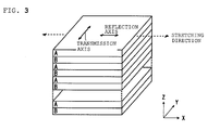
- FIG. 3 is a schematic perspective view of an example of the reflective polarizer.
- the reflective polarizer is a multilayer laminate in which a layer A having birefringence and a layer B substantially free of birefringence are alternately laminated.
- the total number of the layers of such multilayer laminate can be, for example, from 50 to 1,000.
- a refractive index nx of the layer A in an x-axis direction is larger than a refractive index ny thereof in a y-axis direction
- a refractive index nx of the layer B in the x-axis direction and a refractive index ny thereof in the y-axis direction are substantially equal to each other.
- a refractive index difference between the layer A and the layer B is large in the x-axis direction, and is substantially zero in the y-axis direction.
- the x-axis direction serves as a reflection axis and the y-axis direction serves as a transmission axis.
- the refractive index difference between the layer A and the layer B in the x-axis direction is preferably from 0.2 to 0.3. It should be noted that the x-axis direction corresponds to the stretching direction of the reflective polarizer.
- the layer A is preferably constituted of a material that expresses birefringence when stretched.
- Typical examples of such material include naphthalene dicarboxylic acid polyester (such as polyethylene naphthalate),polycarbonate,and an acrylic resin (such as polymethyl methacrylate). Of those, polyethylene naphthalate is preferred.
- the layer B is preferably constituted of a material that is substantially free from expressing birefringence even when stretched.
- a typical example of such material is the copolyester of naphthalene dicarboxylic acid and terephthalic acid.
- the reflective polarizer transmits light having a first polarization direction (such as a p-wave) at an interface between the layer A and the layer B, and reflects light having a second polarization direction perpendicular to the first polarization direction (such as an s-wave) at the interface. Part of the reflected light is transmitted as light having the first polarization direction, and other part thereof is reflected as light having the second polarization direction at the interface between the layer A and the layer B.
- a first polarization direction such as a p-wave
- the total thickness of the reflective polarizer can be appropriately set in accordance with, for example, purposes and the total number of the layers in the reflective polarizer.
- the total thickness of the reflective polarizer is preferably from 10 ⁇ m to 150 ⁇ m.
- the reflective polarizer can be typically produced by combining co-extrusion and lateral stretching.
- the co-extrusion can be performed by any appropriate system.
- a feedblock system is permitted, or a multi-manifold system is permitted.
- the material for constituting the layer A and the material for constituting the layer B are extruded in a feed block, and then the resultant is turned into a plurality of layers with a multiplier. It should be noted that such apparatus for turning the materials into the plurality of layers is known to a person skilled in the art.
- the resultant elongatedmultilayer laminate is typically stretched in a direction (TD) perpendicular to a conveying direction.
- the material for constituting the layer A (such as polyethylene naphthalate) is increased in refractive index only in the stretching direction by the lateral stretching, and as a result, expresses birefringence.
- the material for constituting the layer B (such as the copolyester of naphthalene dicarboxylic acid and terephthalic acid) is not increased in refractive index in any direction even by the lateral stretching.
- a reflective polarizer having a reflection axis in the stretching direction (TD) and having a transmission axis in the conveying direction (MD) can be obtained (the TD corresponds to the x-axis direction of FIG. 3 and the MD corresponds to the y-axis direction thereof).
- TD reflection axis in the stretching direction
- MD transmission axis in the conveying direction
- linearly polarized light separation-type reflective polarizer is such a polarizing fiber or polarizing woven fabric as described in Japanese Patent Application Laid-open No. 2009-24318 .
- the performance of the reflective polarizer improves as a refractive index difference in a direction perpendicular to the lengthwise direction of the polarizing fiber becomes smaller and a refractive index difference in the lengthwise direction of the polarizing fiber becomes larger.
- Still another example of the linearly polarized light separation-type reflective polarizer is such a wire grid polarizer as described in Japanese Patent Application Laid-open No. 2011-48630 .
- a commercial product may be directly used as the reflective polarizer, or the commercial product may be subjected to secondary processing (such as stretching) before use.
- Examples of the commercial product include a product available under the trade name "DBEF” from 3M Company and a product available under the trade name “APF” from 3M Company.
- the wire grid polarizer is, for example, a product available under the trade name "WGFTM” from Asahi Kasei E-materials.
- any appropriate apparatus can be used as the image display apparatus.
- Examples thereof include a liquid crystal display apparatus, an organic EL display apparatus, and a plasma display apparatus. Description is given below by taking the liquid crystal display apparatus as a typical example.
- the liquid crystal display apparatus there is used an image display apparatus including, as illustrated in FIG. 1 , a liquid crystal panel including a liquid crystal cell 131, a second polarizing plate 132 arranged on the viewer side of the liquid crystal cell 131, and a third polarizing plate 133 arranged on the back surface side of the liquid crystal cell 131.
- the image display apparatus can include any appropriate other member (such as a backlight unit) as required.
- the liquid crystal cell 131 has a pair of substrates and a liquid crystal layer serving as a display medium sandwiched between the substrates.
- a color filter and a black matrix are arranged on one of the substrates, and a switching element for controlling the electrooptical characteristics of a liquid crystal, a scanning line for providing the switching element with a gate signal and a signal line for providing the element with a source signal, and a pixel electrode and a counter electrode are arranged on the other substrate.
- An interval between the substrates (cellgap) can be controlled with, for example, aspacer.
- an alignment film formed of polyimide can be arranged on the side of each of the substrates to be brought into contact with the liquid crystal layer.
- the liquid crystal layer contains liquid crystal molecules aligned in a homogeneous array under a state in which no electric field is present.
- Typical examples of a driving mode using the liquid crystal layer showing such three-dimensional refractive index include an in-plane switching (IPS) mode and a fringe field switching (FFS) mode.
- IPS in-plane switching
- FFS fringe field switching
- the IPS mode includes a super in-plane switching (S-IPS) mode and an advanced super in-plane switching (AS-IPS) mode each adopting a V-shaped electrode, a zigzag electrode, or the like.
- the FFS mode includes an advanced fringe field switching (A-FFS) mode and an ultra fringe field switching (U-FFS) mode each adopting a V-shaped electrode, a zigzag electrode, or the like.
- the liquid crystal layer contains liquid crystal molecules aligned in a homeotropic array under a state in which no electric field is present.
- a driving mode using the liquid crystal molecules aligned in the homeotropic array under a state in which no electric field is present is, for example, a vertical alignment (VA) mode.
- VA mode includes a multi-domain VA (MVA) mode.
- Such polarizing plate as described in the section B is used as each of the second polarizing plate and the third polarizing plate.
- the second polarizing plate and the third polarizing plate can be arranged so that the absorption axes of their respective polarizers are substantially perpendicular or parallel to each other to enable the viewing of an image.
- the second polarizing plate is preferably arranged so that the absorption axis of the second polarizing plate and the reflection axis of the half mirror are parallel to each other.
- the second polarizing plate 132 is omitted from the image display apparatus (liquid crystal display apparatus) 130 illustrated in FIG. 1 . That is, in this embodiment, a liquid crystal display apparatus free of a polarizing plate on the viewer side of its liquid crystal cell is used. In this embodiment, the brightness of the image display mirror for a vehicle can be improved because an optical loss due to the second polarizing plate can be eliminated.
- the first polarizing plate and the third polarizing plate are arranged so that the absorption axes of their respective polarizers are substantially perpendicular or parallel to each other to enable the viewing of an image.
- the liquid crystal display apparatus can be configured so that polarized light output from the liquid crystal display apparatus can be transmitted through the half mirror.
- the ⁇ /4 plate is arranged on the viewer side (i.e., the side opposite to the half mirror) of the first polarizing plate.
- a front retardation R 0 of the ⁇ /4 plate at a wavelength of 590 nm is from 90 nm to 190 nm, preferably from 100 nm to 180 nm, more preferably from 110 nm to 170 nm.
- the ⁇ /4 plate shows any appropriate refractive index ellipsoid as long as the plate has the relationship of nx>ny.
- the refractive index ellipsoid of the ⁇ /4 plate shows the relationship of nx>nz>ny or nx>ny ⁇ nz.
- An angle between the absorption axis of the polarizer of the first polarizing plate and the slow axis of the ⁇ /4 plate is preferably from +40° to +50° or from -40° to -50°, more preferably from +43° to +47° or from -43° to -47°, still more preferably +45° or -45°.
- the laminated structure of the first polarizing plate and the ⁇ /4 plate can function as a circularly polarizing plate.
- any appropriate material can be used as a material for constituting the ⁇ /4 plate as long as the effects of the present invention are obtained.
- a typical example thereof is a stretched film of a polymer film.
- a resin for forming the polymer film include a polycarbonate-based resin and a cycloolefin-based resin.
- a method of producing the ⁇ /4 plate is not particularly limited, but the ⁇ /4 plate can be obtained by, for example, stretching the polymer film at a temperature of from about 100°C to about 250°C and at a stretching ratio of from about 1.1 times to about 2.5 times.
- the front retardation and thickness direction retardation of the ⁇ /4 plate can be controlled by adjusting the stretching ratio and stretching temperature of the polymer film.
- the thickness and total light transmittance of the ⁇ /4 plate are preferably about 200 ⁇ m or less and 80% or more, respectively, though the thickness and the total light transmittance are not particularly limited thereto.
Landscapes
- Physics & Mathematics (AREA)
- Engineering & Computer Science (AREA)
- Multimedia (AREA)
- Mechanical Engineering (AREA)
- Optics & Photonics (AREA)
- General Physics & Mathematics (AREA)
- Nonlinear Science (AREA)
- Chemical & Material Sciences (AREA)
- Crystallography & Structural Chemistry (AREA)
- Mathematical Physics (AREA)
- Spectroscopy & Molecular Physics (AREA)
- Polarising Elements (AREA)
- Liquid Crystal (AREA)
- Devices For Indicating Variable Information By Combining Individual Elements (AREA)
Abstract
Description
- The present invention relates to an image display mirror for a vehicle.
- A technology involving combining a rear-view mirror for a vehicle with an image display apparatus to display an image has heretofore been known. For example,
Japanese Patent No. 5273286 - Such image display mirror involves a problem in that, for example, when the quantity of light from the rear of a vehicle is large, the reflected image inhibits the visibility of an image displayed on the monitor.
Japanese Patent No. 5273286 - However, when it is difficult to turn the reflected image provided by the half mirror into the image that does not inhibit the visibility of the monitor image, e.g., when the image display mirrorof
Japanese Patent No. 5273286 - The present invention has been made to solve the conventional problems, and an object of the present invention is to provide an image display mirror that includes a half mirror and an image display apparatus, reduces an influence of a reflected image provided by the half mirror, and is excellent in visibility of an image displayed on the image display apparatus.
- An image display mirror for a vehicle according to one embodiment of the present invention includes: a first polarizing plate arranged removably and attachably; a half mirror having a reflection axis and being configured to reflect polarized light; and an image display apparatus in the stated order from a viewer side, in which: the first polarizing plate has a polarizer; and when the first polarizing plate is in an attached state, an absorption axis of the polarizer and the reflection axis of the half mirror are parallel to each other.
- In one embodiment of the present invention, attached and removed states of the first polarizing plate are switched when an image is displayed on the image display apparatus and when the image is not displayed thereon; and when the image is displayed, the first polarizing plate is arranged between the half mirror and a viewer.
- In one embodiment of the present invention, the first polarizing plate is subjected to a low-reflection treatment.
- In one embodiment of the present invention, the image display mirror for a vehicle further includes a λ/4 plate on a viewer side of the first polarizing plate.
- In one embodiment of the present invention, the image display apparatus includes a liquid crystal display apparatus including a liquid crystal cell, and the liquid crystal display apparatus is free of a polarizing plate on a viewer side of the liquid crystal cell.
- According to another embodiment of the present invention, there is provided a method of observing surroundings of a vehicle. The method is a method by which a driver of a vehicle observes surroundings of the vehicle with the above-mentioned image display mirror for a vehicle, the method including: switching attached and removed states of the first polarizing plate when an image is displayed on the image display apparatus and when the image is not displayed thereon; and arranging, when the image is displayed, the first polarizingplate between the half mirror and the driver of the vehicle.
- The image display mirror for a vehicle according to the embodiment of the present invention includes the polarizing plate arranged removably and attachably, the half mirror configured to reflect polarized light, and the image display apparatus in the stated order from the viewer side. In such image display mirror for a vehicle, when an image is displayed on the image display apparatus, the image can be viewed through the polarizing plate. As a result, an influence of a reflected image provided by the half mirror is reduced and hence the visibility of the image displayed on the image display apparatus improves. In addition, when the image is not displayed on the image display apparatus, the reflected image can be viewed without through the polarizing plate, and hence the half mirror can express a function as a mirror.
-
-
FIG. 1 is a schematic sectional view of an image display mirror according to one embodiment of the present invention. -
FIG. 2A and FIG. 2B are each a schematic view for illustrating an action according to the one embodiment of the present invention. -
FIG. 3 is a schematic perspective view of an example of a reflective polarizer to be used in the one embodiment of the present invention. - Embodiments of the present invention are hereinafter described with reference to the drawings. However, the present invention is not limited to these embodiments.
-
FIG. 1 is a schematic sectional view of an image display mirror according to one embodiment of the present invention. Animage display mirror 100 for a vehicle includes a firstpolarizing plate 110 arranged removably and attachably, ahalf mirror 120, and animage display apparatus 130 in the stated order from a viewer side. Thehalf mirror 120 and theimage display apparatus 130 are preferably arranged so as to be parallel to each other. The image display mirror for a vehicle of this embodiment can be used as, for example, the rear-view mirror (room mirror) of a vehicle. Thehalf mirror 120 has a light-reflecting function and a light-transmitting function. Theimage display mirror 100 for a vehicle enables an occupant (more specifically, a driver) of the vehicle to observe the surroundings (e.g., the rear) of the vehicle by virtue of the light-reflecting function of thehalf mirror 120. In addition, in theimage display mirror 100 for a vehicle, an image displayed on theimage display apparatus 130 can be viewed by virtue of the light-transmitting function of thehalf mirror 120. Theimage display apparatus 130 displays, for example, an image provided by an external camera that mirrors the surroundings (e.g. , the rear) of the vehicle. With such construction, even, for example, when an obstacle (such as a passenger or baggage) is present in the vehicle and hence the surroundings of the vehicle cannot be sufficiently observed with the reflected image of the half mirror, the safety of the vehicle can be secured by displaying the image provided by the external camera on the image display apparatus. It should be noted that, although not illustrated, the image display mirror for a vehicle of the present invention may further include any appropriate other member. - The half mirror is a half mirror that can reflect polarized light. More specifically, the half mirror has a reflection axis and a transmission axis perpendicular to each other, and can reflect polarized light whose polarization direction is parallel to the reflection axis and transmit polarized light whose polarization direction is parallel to the transmission axis.
- When the first polarizing plate is in an attached state, the absorption axis of the polarizer of the first polarizing plate and the reflection axis of the half mirror are parallel to each other. It should be noted that the term "parallel" as used herein includes the case where the axes are substantially parallel to each other. Here, the phrase "substantially parallel" includes the case where an angle between the axes is 0°±10°, and the angle is preferably 0°±7°, more preferably 0°±5°. Inaddition, the term "perpendicular" as used herein includes the case where the axes are substantially perpendicular to each other. Here, the phrase "substantially perpendicular" includes the case where the angle between the axes is 90°±10°, and the angle is preferably 90°±7°, more preferably 90°±5°.
- As described above, the first polarizing plate is arranged removably and attachably. The phrase "arranged removably and attachably" as used herein means that the first polarizing plate is arranged so that a state in which the occupant (more specifically, the driver) of the vehicle serving as a viewer observes the half mirror through the first polarizing plate (also referred to as "attached state") and a state in which the occupant observes the half mirror without through the first polarizingplate (also referred to as "removed state") can be switched. It should be noted that even when the first polarizing plate is physically distant from the half mirror, the state in which the driver of the vehicle observes the half mirror through the first polarizing plate is the attached state of the first polarizing plate. It is preferred that the attached and removed states of the first polarizing plate be switched when the image is displayed on the image display apparatus and when the image is not displayed thereon, and when the image is displayed, the first polarizing plate be arranged between the half mirror and the viewer. In the present invention, the first polarizing plate is arranged removably and attachably, and hence when the image is displayed on the image display apparatus, the image can be viewed through the first polarizing plate. As a result, an influence of the reflected image provided by the half mirror is reduced and hence the visibility of the image displayed on the image display apparatus improves. In addition, when the image is not displayed on the image display apparatus, the reflected image can be viewed without through the first polarizing plate, and hence the half mirror can express a function as a mirror.
-
FIG. 2A and FIG. 2B are each a schematic view for illustrating an action according to the one embodiment of the present invention.FIG. 2A is an illustration of a state in which the reflected image provided by thehalf mirror 120 is subjected to viewing, i.e., the removed state of the first polarizing plate. In this state, the image is not displayed on theimage display apparatus 130, and hence the quantity of light entering from its back surface to be transmitted through thehalf mirror 120 is substantially zero. On the other hand, light entering thehalf mirror 120 from the viewer side is separated into polarized light beams, and polarized light whose polarization direction is perpendicular to a reflection axis A (i.e. , polarized light whose polarization direction is parallel to a transmission axis B) is transmitted through thehalf mirror 120, and polarized light whose polarization direction is parallel to the reflection axis A is reflected by thehalf mirror 120. When thehalf mirror 120 reflects the polarized light as described above, the occupant of the vehicle can view the reflected image provided by thehalf mirror 120.FIG. 2B is an illustration of a state in which the image is displayed on theimage display apparatus 130, i.e., the attached state of the firstpolarizing plate 110. In this state, the polarized light that can be reflected by thehalf mirror 120 is removed by the firstpolarizing plate 110 because an absorption axis C of the polarizer of the firstpolarizing plate 110 and the reflection axis A of thehalf mirror 120 are parallel to each other. As a result, the reflected image provided by thehalf mirror 120 becomes difficult to view. On the other hand, the light transmitted through thehalf mirror 120 from theimage display apparatus 130 is polarized light that can be transmitted through the firstpolarizing plate 110, and hence the image of theimage display apparatus 130 is subjected to the viewing. As described above, according to the image display mirror for a vehicle of the present invention, the influence of the reflected image provided by thehalf mirror 120 is reduced and hence the visibility of the image displayed on theimage display apparatus 130 can be improved. - Any appropriate mechanism can be adopted as a mechanism for attaching and removing the first polarizing plate as long as the effects of the present invention are obtained. For example, such a mechanism that the image display mirror for a vehicle is housed in a housing, and the first polarizing plate is manually or electrically attached and removed in the housing is permitted, such a mechanism that the first polarizing plate is hung on the viewer side of the half mirror to be brought into the attached state is permitted, or such a mechanism that the first polarizing plate is caused to escape toward a side surface of the image display mirror for a vehicle to be brought into the removed state is permitted.
- The half mirror and the image display apparatus may be brought into contact with each other or may be out of contact with each other. It is preferred that a gap between the half mirror and the image display apparatus be filled with a transparent resin, and both the members be brought into close contact with each other. When both the members are brought into close contact with each other as described above, an image display mirror for a vehicle excellent inefficiency with which light is utilized and excellent invisibility of a displayed image can be obtained. Any appropriate resin film, pressure-sensitive adhesive, or the like can be used in interlayer filling. A pressure-sensitive adhesive excellent in transparency is preferably used as the pressure-sensitive adhesive. Examples thereof include an acrylic pressure-sensitive adhesive, a silicone-based pressure-sensitive adhesive, and a rubber-based pressure-sensitive adhesive.
- In one embodiment, a λ/4 plate can be arranged on the viewer side (i.e., the side opposite to the half mirror) of the first polarizing plate. The λ/4 plate has a function of transforming linearly polarized light into circularly polarized light (or circularly polarized light into linearly polarized light) by arranging its slow axis at an angle of about +45° or about -45° relative to the absorption axis of the first polarizing plate (details are described later). The arrangement of the λ/4 plate can provide an image display mirror for a vehicle excellent in visibility for a user of a pair of polarized sunglasses. It should be noted that the λ/4 plate may be brought into contact with the first polarizing plate or may be out of contact therewith. In addition, the λ/4 plate and the first polarizing plate may be bonded to each other through a pressure-sensitive adhesive layer. Further, the λ/4 plate may be arranged removably and attachably.
- The first polarizing plate typically has a polarizer and a protective layer arranged on one side, or each of both sides, of the polarizer. The polarizer is typically an absorption-type polarizer.
- The transmittance (also referred to as "single axis transmittance") of the polarizer at a wavelength of 589 nm is preferably 41% or more, more preferably 42% or more. It should be noted that a theoretical upper limit for the single axis transmittance is 50%. In addition, its polarization degree is preferably from 99.5% to 100%, more preferably from 99.9% to 100%.
- Any appropriate polarizer may be used as the polarizer. Examples thereof include: a polarizer obtained by adsorbing a dichroic substance, such as iodine or a dichroic dye, onto a hydrophilic polymer film, such as a polyvinyl alcohol-based film, a partially formalized polyvinyl alcohol-based film, or an ethylene-vinyl acetate copolymer-based partially saponified film, and subjecting the resultant film to uniaxial stretching; and polyene-based alignment films, such as a dehydrated product of polyvinyl alcohol and a dehydrochlorinated product of polyvinyl chloride. Of those, a polarizer obtained by adsorbing a dichroic substance, such as iodine, onto a polyvinyl alcohol-based film and subj ecting the resultant film to uniaxial stretching is particularly preferred because of its high polarized dichromaticity. The polarizer has a thickness of preferably from 0.5 µm to 80 µm.
- The polarizer obtained by adsorbing iodine onto a polyvinyl alcohol-based film and subjecting the resultant film to uniaxial stretching is typically produced by dyeing polyvinyl alcohol through immersion in an aqueous solution of iodine and stretching the resultant film at a ratio of from 3 times to 7 times with respect to its original length. The stretching may be carried out after the dyeing, the stretching may be carried out during the dyeing, or the stretching may be carried out before the dyeing. The polarizer may be produced by subjecting the film to treatments such as swelling, cross-linking, adjusting, washing with water, and drying in addition to the stretching and the dyeing.
- Any appropriate film may be used as the protective layer. As a material for the main component of such film, there are specif ically given, for example: cellulose-based resins, such as triacetylcellulose (TAC); and transparent resins, such as (meth)acrylic, polyester-based, polyvinyl alcohol-based, polycarbonate-based, polyamide-based, polyimide-based, polyether sulfone-based, polysulfone-based, polystyrene-based, polynorbornene-based, polyolefin-based, or acetate-based transparent resins. In addition, examples thereof further include thermosetting resins and UV curable resins, such as acrylic, urethane-based, acrylic urethane-based, epoxy-based, or silicone-based thermosetting resins and UV curable resins. In addition, examples thereof further include glassy polymers, such as a siloxane-based polymer. In addition, a polymer film described in
Japanese Patent Application Laid-open No. 2001-343529 WO01/37007A - In one embodiment, the first polarizing plate is subjected to a low-reflection treatment. The surface of the protective layer is preferably subjected to the low-reflection treatment. The low-reflection treatment is, for example, a treatment involving forming a layer, such as a fluorine-based resin layer, a multilayer metal-deposited layer, an optical interference layer, or a layer having a fine uneven shape (e.g., a moth-eye structure).
- A reflective polarizing plate including a reflective polarizer is used as the half mirror. The reflective polarizer has functions of transmitting polarized light in a specific polarization state (polarization direction) and reflecting light in a polarization state except the foregoing. The reflective polarizer is preferably of a linearly polarized light separation type.
-
FIG. 3 is a schematic perspective view of an example of the reflective polarizer. The reflective polarizer is a multilayer laminate in which a layer A having birefringence and a layer B substantially free of birefringence are alternately laminated. The total number of the layers of such multilayer laminate can be, for example, from 50 to 1,000. In the illustrated example, a refractive index nx of the layer A in an x-axis direction is larger than a refractive index ny thereof in a y-axis direction, and a refractive index nx of the layer B in the x-axis direction and a refractive index ny thereof in the y-axis direction are substantially equal to each other. Therefore, a refractive index difference between the layer A and the layer B is large in the x-axis direction, and is substantially zero in the y-axis direction. As a result, the x-axis direction serves as a reflection axis and the y-axis direction serves as a transmission axis. The refractive index difference between the layer A and the layer B in the x-axis direction is preferably from 0.2 to 0.3. It should be noted that the x-axis direction corresponds to the stretching direction of the reflective polarizer. - The layer A is preferably constituted of a material that expresses birefringence when stretched. Typical examples of such material include naphthalene dicarboxylic acid polyester (such as polyethylene naphthalate),polycarbonate,and an acrylic resin (such as polymethyl methacrylate). Of those, polyethylene naphthalate is preferred. The layer B is preferably constituted of a material that is substantially free from expressing birefringence even when stretched. A typical example of such material is the copolyester of naphthalene dicarboxylic acid and terephthalic acid.
- The reflective polarizer transmits light having a first polarization direction (such as a p-wave) at an interface between the layer A and the layer B, and reflects light having a second polarization direction perpendicular to the first polarization direction (such as an s-wave) at the interface. Part of the reflected light is transmitted as light having the first polarization direction, and other part thereof is reflected as light having the second polarization direction at the interface between the layer A and the layer B.
- The total thickness of the reflective polarizer can be appropriately set in accordance with, for example, purposes and the total number of the layers in the reflective polarizer. The total thickness of the reflective polarizer is preferably from 10 µm to 150 µm.
- The reflective polarizer can be typically produced by combining co-extrusion and lateral stretching. The co-extrusion can be performed by any appropriate system. For example, a feedblock system is permitted, or a multi-manifold system is permitted. For example, the material for constituting the layer A and the material for constituting the layer B are extruded in a feed block, and then the resultant is turned into a plurality of layers with a multiplier. It should be noted that such apparatus for turning the materials into the plurality of layers is known to a person skilled in the art. Next, the resultant elongatedmultilayer laminate is typically stretched in a direction (TD) perpendicular to a conveying direction. The material for constituting the layer A (such as polyethylene naphthalate) is increased in refractive index only in the stretching direction by the lateral stretching, and as a result, expresses birefringence. The material for constituting the layer B (such as the copolyester of naphthalene dicarboxylic acid and terephthalic acid) is not increased in refractive index in any direction even by the lateral stretching. As a result, a reflective polarizer having a reflection axis in the stretching direction (TD) and having a transmission axis in the conveying direction (MD) can be obtained (the TD corresponds to the x-axis direction of
FIG. 3 and the MD corresponds to the y-axis direction thereof). It should be noted that a stretching operation can be performed with any appropriate apparatus. - Another example of the linearly polarized light separation-type reflective polarizer is such a polarizing fiber or polarizing woven fabric as described in
Japanese Patent Application Laid-open No. 2009-24318 Japanese Patent Application Laid-open No. 2011-48630 - A commercial product may be directly used as the reflective polarizer, or the commercial product may be subjected to secondary processing (such as stretching) before use. Examples of the commercial product include a product available under the trade name "DBEF" from 3M Company and a product available under the trade name "APF" from 3M Company. In addition, the wire grid polarizer is, for example, a product available under the trade name "WGFTM" from Asahi Kasei E-materials.
- Any appropriate apparatus can be used as the image display apparatus. Examples thereof include a liquid crystal display apparatus, an organic EL display apparatus, and a plasma display apparatus. Description is given below by taking the liquid crystal display apparatus as a typical example. In one embodiment, as the liquid crystal display apparatus, there is used an image display apparatus including, as illustrated in
FIG. 1 , a liquid crystal panel including aliquid crystal cell 131, a secondpolarizing plate 132 arranged on the viewer side of theliquid crystal cell 131, and a thirdpolarizing plate 133 arranged on the back surface side of theliquid crystal cell 131. It should be noted that, although not illustrated, the image display apparatus can include any appropriate other member (such as a backlight unit) as required. - The
liquid crystal cell 131 has a pair of substrates and a liquid crystal layer serving as a display medium sandwiched between the substrates. In a general construction, a color filter and a black matrix are arranged on one of the substrates, and a switching element for controlling the electrooptical characteristics of a liquid crystal, a scanning line for providing the switching element with a gate signal and a signal line for providing the element with a source signal, and a pixel electrode and a counter electrode are arranged on the other substrate. An interval between the substrates (cellgap) can be controlled with, for example, aspacer. For example, an alignment film formed of polyimide can be arranged on the side of each of the substrates to be brought into contact with the liquid crystal layer. - In one embodiment, the liquid crystal layer contains liquid crystal molecules aligned in a homogeneous array under a state in which no electric field is present. Such liquid crystal layer (resultantly the liquid crystal cell) typically shows a three-dimensional refractive index of nx>ny=nz. It should be noted that the expression "ny=nz" as used herein includes not only the case where ny and nz are completely equal to each other but also the case where ny and nz are substantially equal to each other. Typical examples of a driving mode using the liquid crystal layer showing such three-dimensional refractive index include an in-plane switching (IPS) mode and a fringe field switching (FFS) mode. It should be noted that the IPS mode includes a super in-plane switching (S-IPS) mode and an advanced super in-plane switching (AS-IPS) mode each adopting a V-shaped electrode, a zigzag electrode, or the like. In addition, the FFS mode includes an advanced fringe field switching (A-FFS) mode and an ultra fringe field switching (U-FFS) mode each adopting a V-shaped electrode, a zigzag electrode, or the like.
- Inanotherembodiment, the liquid crystal layer contains liquid crystal molecules aligned in a homeotropic array under a state in which no electric field is present. Such liquid crystal layer (resultantly the liquid crystal cell) typically shows a three-dimensional refractive index of nz>nx=ny. A driving mode using the liquid crystal molecules aligned in the homeotropic array under a state in which no electric field is present is, for example, a vertical alignment (VA) mode. The VA mode includes a multi-domain VA (MVA) mode.
- Such polarizing plate as described in the section B is used as each of the second polarizing plate and the third polarizing plate.
- The second polarizing plate and the third polarizing plate can be arranged so that the absorption axes of their respective polarizers are substantially perpendicular or parallel to each other to enable the viewing of an image. In addition, the second polarizing plate is preferably arranged so that the absorption axis of the second polarizing plate and the reflection axis of the half mirror are parallel to each other.
- In one embodiment, the second
polarizing plate 132 is omitted from the image display apparatus (liquid crystal display apparatus) 130 illustrated inFIG. 1 . That is, in this embodiment, a liquid crystal display apparatus free of a polarizing plate on the viewer side of its liquid crystal cell is used. In this embodiment, the brightness of the image display mirror for a vehicle can be improved because an optical loss due to the second polarizing plate can be eliminated. In this embodiment, when the first polarizing plate is brought into the attached state, the first polarizing plate and the third polarizing plate are arranged so that the absorption axes of their respective polarizers are substantially perpendicular or parallel to each other to enable the viewing of an image. In addition, in this embodiment, the liquid crystal display apparatus can be configured so that polarized light output from the liquid crystal display apparatus can be transmitted through the half mirror. - In one embodiment, as described above, the λ/4 plate is arranged on the viewer side (i.e., the side opposite to the half mirror) of the first polarizing plate.
- A front retardation R0 of the λ/4 plate at a wavelength of 590 nm is from 90 nm to 190 nm, preferably from 100 nm to 180 nm, more preferably from 110 nm to 170 nm. It should be noted that the front retardation R0 in this specification is determined from the equation "R0=(nx-ny)×d" where nx represents a refractive index in the direction in which an in-plane refractive index becomes maximum (i.e., a slow axis direction), ny represents a refractive index in a direction perpendicular to the slow axis in a plane (i.e., a fast axis direction), and d (nm) represents the thickness of a retardation film; these parameters are values under 23°C. The λ/4 plate shows any appropriate refractive index ellipsoid as long as the plate has the relationship of nx>ny. For example, the refractive index ellipsoid of the λ/4 plate shows the relationship of nx>nz>ny or nx>ny≥nz.
- An angle between the absorption axis of the polarizer of the first polarizing plate and the slow axis of the λ/4 plate is preferably from +40° to +50° or from -40° to -50°, more preferably from +43° to +47° or from -43° to -47°, still more preferably +45° or -45°. When the first polarizing plate and the λ/4 plate are arranged so as to show such relationship, the laminated structure of the first polarizing plate and the λ/4 plate can function as a circularly polarizing plate.
- Any appropriate material can be used as a material for constituting the λ/4 plate as long as the effects of the present invention are obtained. A typical example thereof is a stretched film of a polymer film. Examples of a resin for forming the polymer film include a polycarbonate-based resin and a cycloolefin-based resin. A method of producing the λ/4 plate is not particularly limited, but the λ/4 plate can be obtained by, for example, stretching the polymer film at a temperature of from about 100°C to about 250°C and at a stretching ratio of from about 1.1 times to about 2.5 times. The front retardation and thickness direction retardation of the λ/4 plate can be controlled by adjusting the stretching ratio and stretching temperature of the polymer film. The thickness and total light transmittance of the λ/4 plate are preferably about 200 µm or less and 80% or more, respectively, though the thickness and the total light transmittance are not particularly limited thereto.
Claims (6)
- An image display mirror (100) for a vehicle, comprising: a first polarizing plate (110) arranged removably and attachably; a half mirror (120) having a reflection axis and being configured to reflect polarized light; and an image display apparatus (130) in the stated order from a viewer side, wherein:the first polarizing plate (110) has a polarizer; andwhen the first polarizing plate (110) is in an attached state, an absorption axis of the polarizer and the reflection axis of the half mirror (120) are parallel to each other.
- The image display mirror (100) for a vehicle according to claim 1, wherein:attached and removed states of the first polarizing plate (110) are switched when an image is displayed on the image display apparatus (130) and when the image is not displayed thereon; andwhen the image is displayed, the first polarizing plate (110) is arranged between the half mirror (120) and a viewer.
- The image display mirror (100) for a vehicle according to claim 1, wherein the first polarizing plate (110) is subjected to a low-reflection treatment.
- The image display mirror (100) for a vehicle according to claim 1, further comprising a λ/4 plate on a viewer side of the first polarizing plate (110).
- The image display mirror (100) for a vehicle according to claim 1, wherein:the image display apparatus (130) comprises a liquid crystal display apparatus including a liquid crystal cell; andthe liquid crystal display apparatus is free of a polarizing plate on a viewer side of the liquid crystal cell.
- A method by which a driver of a vehicle observes surroundings of the vehicle with the image display mirror (100) for a vehicle of claim 1, the method comprising:switching attached and removed states of the first polarizing plate (110) when an image is displayed on the image display apparatus (130) and when the image is not displayed thereon; andarranging, when the image is displayed, the first polarizing plate (110) between the half mirror (120) and the driver of the vehicle.
Applications Claiming Priority (1)
| Application Number | Priority Date | Filing Date | Title |
|---|---|---|---|
| JP2015018655A JP6457283B2 (en) | 2015-02-02 | 2015-02-02 | Video display mirror for vehicles |
Publications (2)
| Publication Number | Publication Date |
|---|---|
| EP3050754A1 true EP3050754A1 (en) | 2016-08-03 |
| EP3050754B1 EP3050754B1 (en) | 2022-06-01 |
Family
ID=55272393
Family Applications (1)
| Application Number | Title | Priority Date | Filing Date |
|---|---|---|---|
| EP16153593.5A Active EP3050754B1 (en) | 2015-02-02 | 2016-02-01 | Image display mirror for a vehicle |
Country Status (5)
| Country | Link |
|---|---|
| US (1) | US9616816B2 (en) |
| EP (1) | EP3050754B1 (en) |
| JP (1) | JP6457283B2 (en) |
| KR (1) | KR102418070B1 (en) |
| CN (1) | CN105842902B (en) |
Families Citing this family (3)
| Publication number | Priority date | Publication date | Assignee | Title |
|---|---|---|---|---|
| JP6571935B2 (en) * | 2015-01-14 | 2019-09-04 | 日東電工株式会社 | Video display mirror for vehicles |
| KR102512320B1 (en) * | 2016-10-12 | 2023-03-21 | 삼성디스플레이 주식회사 | Reflective display device |
| JP2018112616A (en) | 2017-01-10 | 2018-07-19 | 富士フイルム株式会社 | Laminate, manufacturing method of laminate, and vehicle room mirror |
Citations (7)
| Publication number | Priority date | Publication date | Assignee | Title |
|---|---|---|---|---|
| WO2001037007A1 (en) | 1999-11-12 | 2001-05-25 | Kaneka Corporation | Transparent film |
| JP2001343529A (en) | 2000-03-30 | 2001-12-14 | Kanegafuchi Chem Ind Co Ltd | Protective film for polarizer and its manufacturing method |
| JP2009024318A (en) | 2007-06-19 | 2009-02-05 | Nitto Denko Corp | Polarizing fiber, polarizer, polarizing plate, laminated optical film, and image display |
| US20090096937A1 (en) * | 2007-08-16 | 2009-04-16 | Bauer Frederick T | Vehicle Rearview Assembly Including a Display for Displaying Video Captured by a Camera and User Instructions |
| US20090296190A1 (en) * | 2004-07-12 | 2009-12-03 | Gentex Corporation | Rearview Mirror Assemblies With Anisotropic Polymer Laminates |
| JP2011048630A (en) | 2009-08-27 | 2011-03-10 | Fujitsu Ltd | Method, program, server, and system for supporting criminal investigation |
| JP5273286B1 (en) | 2011-12-09 | 2013-08-28 | 日産自動車株式会社 | Video display mirror |
Family Cites Families (15)
| Publication number | Priority date | Publication date | Assignee | Title |
|---|---|---|---|---|
| JPH05273286A (en) | 1992-03-26 | 1993-10-22 | Mitsubishi Rayon Co Ltd | Adapter board for electric inspection of printed wiring board and electric inspection method using it |
| KR100250808B1 (en) * | 1997-12-12 | 2000-05-01 | 김성년 | Polarizing 3-d picture device using thin film transistor liquid crystal display |
| JP3419766B2 (en) * | 2000-02-29 | 2003-06-23 | 株式会社日立製作所 | Apparatus that can switch between image display state and mirror state, and equipment equipped with this |
| KR100775394B1 (en) * | 2001-12-28 | 2007-11-12 | 엘지.필립스 엘시디 주식회사 | Liquid crystal display device having a reflective mode |
| TWI266907B (en) * | 2002-07-24 | 2006-11-21 | Nitto Denko Corp | Polarizing device, optical thin film using the same, and image display device using the same |
| JP2005321717A (en) * | 2004-05-11 | 2005-11-17 | Koninkl Philips Electronics Nv | Display apparatus with mirror function and mobile information apparatus |
| US7502156B2 (en) * | 2004-07-12 | 2009-03-10 | Gentex Corporation | Variable reflectance mirrors and windows |
| US20060209239A1 (en) * | 2005-03-18 | 2006-09-21 | Toppoly Optoelectronics Corporation | Anti-reflective polarizing plate and uses thereof |
| RU2008117411A (en) * | 2005-10-03 | 2009-11-10 | Конинклейке Филипс Электроникс Н.В. (Nl) | DEVICE FOR PLAYING THE IMAGE |
| ATE509296T1 (en) * | 2006-03-09 | 2011-05-15 | Gentex Corp | VEHICLE REARVIEW MIRROR ARRANGEMENT WITH HIGH INTENSITY DISPLAY |
| KR101237149B1 (en) * | 2006-06-28 | 2013-02-25 | 엘지디스플레이 주식회사 | Liquid Crystal Display Device And Fabricating And Driving Method Thereof |
| CN102216843B (en) * | 2008-07-10 | 2014-08-27 | 金泰克斯公司 | Rearview mirror assemblies with anisotropic polymer laminates |
| JP5125945B2 (en) * | 2008-09-26 | 2013-01-23 | カシオ計算機株式会社 | Electronic device with display |
| JP2010221899A (en) * | 2009-03-24 | 2010-10-07 | Murakami Corp | Vehicular mirror with monitor |
| JP5991689B2 (en) * | 2012-07-25 | 2016-09-14 | 京セラディスプレイ株式会社 | Liquid crystal display element |
-
2015
- 2015-02-02 JP JP2015018655A patent/JP6457283B2/en active Active
-
2016
- 2016-01-29 KR KR1020160011702A patent/KR102418070B1/en active IP Right Grant
- 2016-02-01 EP EP16153593.5A patent/EP3050754B1/en active Active
- 2016-02-01 US US15/011,853 patent/US9616816B2/en active Active
- 2016-02-02 CN CN201610072868.1A patent/CN105842902B/en active Active
Patent Citations (7)
| Publication number | Priority date | Publication date | Assignee | Title |
|---|---|---|---|---|
| WO2001037007A1 (en) | 1999-11-12 | 2001-05-25 | Kaneka Corporation | Transparent film |
| JP2001343529A (en) | 2000-03-30 | 2001-12-14 | Kanegafuchi Chem Ind Co Ltd | Protective film for polarizer and its manufacturing method |
| US20090296190A1 (en) * | 2004-07-12 | 2009-12-03 | Gentex Corporation | Rearview Mirror Assemblies With Anisotropic Polymer Laminates |
| JP2009024318A (en) | 2007-06-19 | 2009-02-05 | Nitto Denko Corp | Polarizing fiber, polarizer, polarizing plate, laminated optical film, and image display |
| US20090096937A1 (en) * | 2007-08-16 | 2009-04-16 | Bauer Frederick T | Vehicle Rearview Assembly Including a Display for Displaying Video Captured by a Camera and User Instructions |
| JP2011048630A (en) | 2009-08-27 | 2011-03-10 | Fujitsu Ltd | Method, program, server, and system for supporting criminal investigation |
| JP5273286B1 (en) | 2011-12-09 | 2013-08-28 | 日産自動車株式会社 | Video display mirror |
Also Published As
| Publication number | Publication date |
|---|---|
| CN105842902A (en) | 2016-08-10 |
| CN105842902B (en) | 2020-09-25 |
| US9616816B2 (en) | 2017-04-11 |
| KR20160094872A (en) | 2016-08-10 |
| US20160221508A1 (en) | 2016-08-04 |
| EP3050754B1 (en) | 2022-06-01 |
| JP6457283B2 (en) | 2019-01-23 |
| JP2016142918A (en) | 2016-08-08 |
| KR102418070B1 (en) | 2022-07-06 |
Similar Documents
| Publication | Publication Date | Title |
|---|---|---|
| EP3045353B1 (en) | Image display mirror for a vehicle | |
| EP3045352B1 (en) | Image display mirror for a vehicle | |
| EP3050753B1 (en) | Image display mirror for a vehicle | |
| EP3050726B1 (en) | Vehicle including mirror with image display apparatus | |
| EP3051338B1 (en) | Image display mirror for a vehicle | |
| EP3050754B1 (en) | Image display mirror for a vehicle | |
| JP6677494B2 (en) | Video display mirror for vehicles |
Legal Events
| Date | Code | Title | Description |
|---|---|---|---|
| PUAI | Public reference made under article 153(3) epc to a published international application that has entered the european phase |
Free format text: ORIGINAL CODE: 0009012 |
|
| AK | Designated contracting states |
Kind code of ref document: A1 Designated state(s): AL AT BE BG CH CY CZ DE DK EE ES FI FR GB GR HR HU IE IS IT LI LT LU LV MC MK MT NL NO PL PT RO RS SE SI SK SM TR |
|
| AX | Request for extension of the european patent |
Extension state: BA ME |
|
| STAA | Information on the status of an ep patent application or granted ep patent |
Free format text: STATUS: REQUEST FOR EXAMINATION WAS MADE |
|
| 17P | Request for examination filed |
Effective date: 20170127 |
|
| RBV | Designated contracting states (corrected) |
Designated state(s): AL AT BE BG CH CY CZ DE DK EE ES FI FR GB GR HR HU IE IS IT LI LT LU LV MC MK MT NL NO PL PT RO RS SE SI SK SM TR |
|
| STAA | Information on the status of an ep patent application or granted ep patent |
Free format text: STATUS: EXAMINATION IS IN PROGRESS |
|
| 17Q | First examination report despatched |
Effective date: 20200107 |
|
| STAA | Information on the status of an ep patent application or granted ep patent |
Free format text: STATUS: EXAMINATION IS IN PROGRESS |
|
| GRAP | Despatch of communication of intention to grant a patent |
Free format text: ORIGINAL CODE: EPIDOSNIGR1 |
|
| STAA | Information on the status of an ep patent application or granted ep patent |
Free format text: STATUS: GRANT OF PATENT IS INTENDED |
|
| INTG | Intention to grant announced |
Effective date: 20220128 |
|
| GRAS | Grant fee paid |
Free format text: ORIGINAL CODE: EPIDOSNIGR3 |
|
| GRAA | (expected) grant |
Free format text: ORIGINAL CODE: 0009210 |
|
| STAA | Information on the status of an ep patent application or granted ep patent |
Free format text: STATUS: THE PATENT HAS BEEN GRANTED |
|
| AK | Designated contracting states |
Kind code of ref document: B1 Designated state(s): AL AT BE BG CH CY CZ DE DK EE ES FI FR GB GR HR HU IE IS IT LI LT LU LV MC MK MT NL NO PL PT RO RS SE SI SK SM TR |
|
| REG | Reference to a national code |
Ref country code: GB Ref legal event code: FG4D |
|
| REG | Reference to a national code |
Ref country code: AT Ref legal event code: REF Ref document number: 1495183 Country of ref document: AT Kind code of ref document: T Effective date: 20220615 Ref country code: CH Ref legal event code: EP |
|
| REG | Reference to a national code |
Ref country code: IE Ref legal event code: FG4D |
|
| REG | Reference to a national code |
Ref country code: DE Ref legal event code: R096 Ref document number: 602016072464 Country of ref document: DE |
|
| REG | Reference to a national code |
Ref country code: LT Ref legal event code: MG9D |
|
| REG | Reference to a national code |
Ref country code: NL Ref legal event code: MP Effective date: 20220601 |
|
| PG25 | Lapsed in a contracting state [announced via postgrant information from national office to epo] |
Ref country code: SE Free format text: LAPSE BECAUSE OF FAILURE TO SUBMIT A TRANSLATION OF THE DESCRIPTION OR TO PAY THE FEE WITHIN THE PRESCRIBED TIME-LIMIT Effective date: 20220601 Ref country code: NO Free format text: LAPSE BECAUSE OF FAILURE TO SUBMIT A TRANSLATION OF THE DESCRIPTION OR TO PAY THE FEE WITHIN THE PRESCRIBED TIME-LIMIT Effective date: 20220901 Ref country code: LT Free format text: LAPSE BECAUSE OF FAILURE TO SUBMIT A TRANSLATION OF THE DESCRIPTION OR TO PAY THE FEE WITHIN THE PRESCRIBED TIME-LIMIT Effective date: 20220601 Ref country code: HR Free format text: LAPSE BECAUSE OF FAILURE TO SUBMIT A TRANSLATION OF THE DESCRIPTION OR TO PAY THE FEE WITHIN THE PRESCRIBED TIME-LIMIT Effective date: 20220601 Ref country code: GR Free format text: LAPSE BECAUSE OF FAILURE TO SUBMIT A TRANSLATION OF THE DESCRIPTION OR TO PAY THE FEE WITHIN THE PRESCRIBED TIME-LIMIT Effective date: 20220902 Ref country code: FI Free format text: LAPSE BECAUSE OF FAILURE TO SUBMIT A TRANSLATION OF THE DESCRIPTION OR TO PAY THE FEE WITHIN THE PRESCRIBED TIME-LIMIT Effective date: 20220601 Ref country code: ES Free format text: LAPSE BECAUSE OF FAILURE TO SUBMIT A TRANSLATION OF THE DESCRIPTION OR TO PAY THE FEE WITHIN THE PRESCRIBED TIME-LIMIT Effective date: 20220601 Ref country code: BG Free format text: LAPSE BECAUSE OF FAILURE TO SUBMIT A TRANSLATION OF THE DESCRIPTION OR TO PAY THE FEE WITHIN THE PRESCRIBED TIME-LIMIT Effective date: 20220901 |
|
| REG | Reference to a national code |
Ref country code: AT Ref legal event code: MK05 Ref document number: 1495183 Country of ref document: AT Kind code of ref document: T Effective date: 20220601 |
|
| PG25 | Lapsed in a contracting state [announced via postgrant information from national office to epo] |
Ref country code: RS Free format text: LAPSE BECAUSE OF FAILURE TO SUBMIT A TRANSLATION OF THE DESCRIPTION OR TO PAY THE FEE WITHIN THE PRESCRIBED TIME-LIMIT Effective date: 20220601 Ref country code: PL Free format text: LAPSE BECAUSE OF FAILURE TO SUBMIT A TRANSLATION OF THE DESCRIPTION OR TO PAY THE FEE WITHIN THE PRESCRIBED TIME-LIMIT Effective date: 20220601 Ref country code: LV Free format text: LAPSE BECAUSE OF FAILURE TO SUBMIT A TRANSLATION OF THE DESCRIPTION OR TO PAY THE FEE WITHIN THE PRESCRIBED TIME-LIMIT Effective date: 20220601 |
|
| PG25 | Lapsed in a contracting state [announced via postgrant information from national office to epo] |
Ref country code: NL Free format text: LAPSE BECAUSE OF FAILURE TO SUBMIT A TRANSLATION OF THE DESCRIPTION OR TO PAY THE FEE WITHIN THE PRESCRIBED TIME-LIMIT Effective date: 20220601 |
|
| PG25 | Lapsed in a contracting state [announced via postgrant information from national office to epo] |
Ref country code: SM Free format text: LAPSE BECAUSE OF FAILURE TO SUBMIT A TRANSLATION OF THE DESCRIPTION OR TO PAY THE FEE WITHIN THE PRESCRIBED TIME-LIMIT Effective date: 20220601 Ref country code: SK Free format text: LAPSE BECAUSE OF FAILURE TO SUBMIT A TRANSLATION OF THE DESCRIPTION OR TO PAY THE FEE WITHIN THE PRESCRIBED TIME-LIMIT Effective date: 20220601 Ref country code: RO Free format text: LAPSE BECAUSE OF FAILURE TO SUBMIT A TRANSLATION OF THE DESCRIPTION OR TO PAY THE FEE WITHIN THE PRESCRIBED TIME-LIMIT Effective date: 20220601 Ref country code: PT Free format text: LAPSE BECAUSE OF FAILURE TO SUBMIT A TRANSLATION OF THE DESCRIPTION OR TO PAY THE FEE WITHIN THE PRESCRIBED TIME-LIMIT Effective date: 20221003 Ref country code: EE Free format text: LAPSE BECAUSE OF FAILURE TO SUBMIT A TRANSLATION OF THE DESCRIPTION OR TO PAY THE FEE WITHIN THE PRESCRIBED TIME-LIMIT Effective date: 20220601 Ref country code: CZ Free format text: LAPSE BECAUSE OF FAILURE TO SUBMIT A TRANSLATION OF THE DESCRIPTION OR TO PAY THE FEE WITHIN THE PRESCRIBED TIME-LIMIT Effective date: 20220601 Ref country code: AT Free format text: LAPSE BECAUSE OF FAILURE TO SUBMIT A TRANSLATION OF THE DESCRIPTION OR TO PAY THE FEE WITHIN THE PRESCRIBED TIME-LIMIT Effective date: 20220601 |
|
| REG | Reference to a national code |
Ref country code: FR Ref legal event code: PLFP Year of fee payment: 8 |
|
| PG25 | Lapsed in a contracting state [announced via postgrant information from national office to epo] |
Ref country code: IS Free format text: LAPSE BECAUSE OF FAILURE TO SUBMIT A TRANSLATION OF THE DESCRIPTION OR TO PAY THE FEE WITHIN THE PRESCRIBED TIME-LIMIT Effective date: 20221001 |
|
| REG | Reference to a national code |
Ref country code: DE Ref legal event code: R097 Ref document number: 602016072464 Country of ref document: DE |
|
| PG25 | Lapsed in a contracting state [announced via postgrant information from national office to epo] |
Ref country code: AL Free format text: LAPSE BECAUSE OF FAILURE TO SUBMIT A TRANSLATION OF THE DESCRIPTION OR TO PAY THE FEE WITHIN THE PRESCRIBED TIME-LIMIT Effective date: 20220601 |
|
| PLBE | No opposition filed within time limit |
Free format text: ORIGINAL CODE: 0009261 |
|
| STAA | Information on the status of an ep patent application or granted ep patent |
Free format text: STATUS: NO OPPOSITION FILED WITHIN TIME LIMIT |
|
| PG25 | Lapsed in a contracting state [announced via postgrant information from national office to epo] |
Ref country code: DK Free format text: LAPSE BECAUSE OF FAILURE TO SUBMIT A TRANSLATION OF THE DESCRIPTION OR TO PAY THE FEE WITHIN THE PRESCRIBED TIME-LIMIT Effective date: 20220601 |
|
| 26N | No opposition filed |
Effective date: 20230302 |
|
| PG25 | Lapsed in a contracting state [announced via postgrant information from national office to epo] |
Ref country code: SI Free format text: LAPSE BECAUSE OF FAILURE TO SUBMIT A TRANSLATION OF THE DESCRIPTION OR TO PAY THE FEE WITHIN THE PRESCRIBED TIME-LIMIT Effective date: 20220601 |
|
| PG25 | Lapsed in a contracting state [announced via postgrant information from national office to epo] |
Ref country code: MC Free format text: LAPSE BECAUSE OF FAILURE TO SUBMIT A TRANSLATION OF THE DESCRIPTION OR TO PAY THE FEE WITHIN THE PRESCRIBED TIME-LIMIT Effective date: 20220601 |
|
| REG | Reference to a national code |
Ref country code: CH Ref legal event code: PL |
|
| REG | Reference to a national code |
Ref country code: BE Ref legal event code: MM Effective date: 20230228 |
|
| GBPC | Gb: european patent ceased through non-payment of renewal fee |
Effective date: 20230201 |
|
| PG25 | Lapsed in a contracting state [announced via postgrant information from national office to epo] |
Ref country code: LU Free format text: LAPSE BECAUSE OF NON-PAYMENT OF DUE FEES Effective date: 20230201 Ref country code: LI Free format text: LAPSE BECAUSE OF NON-PAYMENT OF DUE FEES Effective date: 20230228 Ref country code: CH Free format text: LAPSE BECAUSE OF NON-PAYMENT OF DUE FEES Effective date: 20230228 |
|
| REG | Reference to a national code |
Ref country code: IE Ref legal event code: MM4A |
|
| PG25 | Lapsed in a contracting state [announced via postgrant information from national office to epo] |
Ref country code: GB Free format text: LAPSE BECAUSE OF NON-PAYMENT OF DUE FEES Effective date: 20230201 |
|
| PG25 | Lapsed in a contracting state [announced via postgrant information from national office to epo] |
Ref country code: IT Free format text: LAPSE BECAUSE OF FAILURE TO SUBMIT A TRANSLATION OF THE DESCRIPTION OR TO PAY THE FEE WITHIN THE PRESCRIBED TIME-LIMIT Effective date: 20220601 Ref country code: IE Free format text: LAPSE BECAUSE OF NON-PAYMENT OF DUE FEES Effective date: 20230201 Ref country code: GB Free format text: LAPSE BECAUSE OF NON-PAYMENT OF DUE FEES Effective date: 20230201 |
|
| PG25 | Lapsed in a contracting state [announced via postgrant information from national office to epo] |
Ref country code: BE Free format text: LAPSE BECAUSE OF NON-PAYMENT OF DUE FEES Effective date: 20230228 |
|
| PGFP | Annual fee paid to national office [announced via postgrant information from national office to epo] |
Ref country code: DE Payment date: 20231228 Year of fee payment: 9 |
|
| PGFP | Annual fee paid to national office [announced via postgrant information from national office to epo] |
Ref country code: FR Payment date: 20240103 Year of fee payment: 9 |