EP3050587A1 - Medical injector with rotatable ratcheting plunger - Google Patents
Medical injector with rotatable ratcheting plunger Download PDFInfo
- Publication number
- EP3050587A1 EP3050587A1 EP16158107.9A EP16158107A EP3050587A1 EP 3050587 A1 EP3050587 A1 EP 3050587A1 EP 16158107 A EP16158107 A EP 16158107A EP 3050587 A1 EP3050587 A1 EP 3050587A1
- Authority
- EP
- European Patent Office
- Prior art keywords
- plunger
- actuator
- ratchet teeth
- medical injector
- indexer
- Prior art date
- Legal status (The legal status is an assumption and is not a legal conclusion. Google has not performed a legal analysis and makes no representation as to the accuracy of the status listed.)
- Granted
Links
- 238000006073 displacement reaction Methods 0.000 claims abstract description 31
- 230000033001 locomotion Effects 0.000 claims abstract description 15
- 239000003814 drug Substances 0.000 description 24
- 238000002347 injection Methods 0.000 description 6
- 239000007924 injection Substances 0.000 description 6
- 239000003085 diluting agent Substances 0.000 description 4
- 230000000694 effects Effects 0.000 description 2
- 230000006870 function Effects 0.000 description 2
- 238000000034 method Methods 0.000 description 2
- 229940090048 pen injector Drugs 0.000 description 2
- 230000005540 biological transmission Effects 0.000 description 1
- 229940079593 drug Drugs 0.000 description 1
- 230000002452 interceptive effect Effects 0.000 description 1
- 239000000463 material Substances 0.000 description 1
- 229920001169 thermoplastic Polymers 0.000 description 1
- 239000004416 thermosoftening plastic Substances 0.000 description 1
Images


Classifications
-
- A—HUMAN NECESSITIES
- A61—MEDICAL OR VETERINARY SCIENCE; HYGIENE
- A61M—DEVICES FOR INTRODUCING MEDIA INTO, OR ONTO, THE BODY; DEVICES FOR TRANSDUCING BODY MEDIA OR FOR TAKING MEDIA FROM THE BODY; DEVICES FOR PRODUCING OR ENDING SLEEP OR STUPOR
- A61M5/00—Devices for bringing media into the body in a subcutaneous, intra-vascular or intramuscular way; Accessories therefor, e.g. filling or cleaning devices, arm-rests
- A61M5/178—Syringes
- A61M5/31—Details
- A61M5/315—Pistons; Piston-rods; Guiding, blocking or restricting the movement of the rod or piston; Appliances on the rod for facilitating dosing ; Dosing mechanisms
- A61M5/31565—Administration mechanisms, i.e. constructional features, modes of administering a dose
- A61M5/31576—Constructional features or modes of drive mechanisms for piston rods
- A61M5/31578—Constructional features or modes of drive mechanisms for piston rods based on axial translation, i.e. components directly operatively associated and axially moved with plunger rod
- A61M5/3158—Constructional features or modes of drive mechanisms for piston rods based on axial translation, i.e. components directly operatively associated and axially moved with plunger rod performed by axially moving actuator operated by user, e.g. an injection button
-
- A—HUMAN NECESSITIES
- A61—MEDICAL OR VETERINARY SCIENCE; HYGIENE
- A61M—DEVICES FOR INTRODUCING MEDIA INTO, OR ONTO, THE BODY; DEVICES FOR TRANSDUCING BODY MEDIA OR FOR TAKING MEDIA FROM THE BODY; DEVICES FOR PRODUCING OR ENDING SLEEP OR STUPOR
- A61M5/00—Devices for bringing media into the body in a subcutaneous, intra-vascular or intramuscular way; Accessories therefor, e.g. filling or cleaning devices, arm-rests
- A61M5/178—Syringes
- A61M5/31—Details
- A61M5/315—Pistons; Piston-rods; Guiding, blocking or restricting the movement of the rod or piston; Appliances on the rod for facilitating dosing ; Dosing mechanisms
- A61M5/31533—Dosing mechanisms, i.e. setting a dose
- A61M5/31545—Setting modes for dosing
- A61M5/31548—Mechanically operated dose setting member
- A61M5/3155—Mechanically operated dose setting member by rotational movement of dose setting member, e.g. during setting or filling of a syringe
- A61M5/31553—Mechanically operated dose setting member by rotational movement of dose setting member, e.g. during setting or filling of a syringe without axial movement of dose setting member
-
- A—HUMAN NECESSITIES
- A61—MEDICAL OR VETERINARY SCIENCE; HYGIENE
- A61M—DEVICES FOR INTRODUCING MEDIA INTO, OR ONTO, THE BODY; DEVICES FOR TRANSDUCING BODY MEDIA OR FOR TAKING MEDIA FROM THE BODY; DEVICES FOR PRODUCING OR ENDING SLEEP OR STUPOR
- A61M5/00—Devices for bringing media into the body in a subcutaneous, intra-vascular or intramuscular way; Accessories therefor, e.g. filling or cleaning devices, arm-rests
- A61M5/178—Syringes
- A61M5/31—Details
- A61M5/315—Pistons; Piston-rods; Guiding, blocking or restricting the movement of the rod or piston; Appliances on the rod for facilitating dosing ; Dosing mechanisms
- A61M5/31565—Administration mechanisms, i.e. constructional features, modes of administering a dose
- A61M5/31576—Constructional features or modes of drive mechanisms for piston rods
- A61M5/31578—Constructional features or modes of drive mechanisms for piston rods based on axial translation, i.e. components directly operatively associated and axially moved with plunger rod
- A61M5/31581—Constructional features or modes of drive mechanisms for piston rods based on axial translation, i.e. components directly operatively associated and axially moved with plunger rod performed by rotationally moving or pivoting actuator operated by user, e.g. an injection lever or handle
-
- A—HUMAN NECESSITIES
- A61—MEDICAL OR VETERINARY SCIENCE; HYGIENE
- A61M—DEVICES FOR INTRODUCING MEDIA INTO, OR ONTO, THE BODY; DEVICES FOR TRANSDUCING BODY MEDIA OR FOR TAKING MEDIA FROM THE BODY; DEVICES FOR PRODUCING OR ENDING SLEEP OR STUPOR
- A61M5/00—Devices for bringing media into the body in a subcutaneous, intra-vascular or intramuscular way; Accessories therefor, e.g. filling or cleaning devices, arm-rests
- A61M5/178—Syringes
- A61M5/1782—Devices aiding filling of syringes in situ
-
- A—HUMAN NECESSITIES
- A61—MEDICAL OR VETERINARY SCIENCE; HYGIENE
- A61M—DEVICES FOR INTRODUCING MEDIA INTO, OR ONTO, THE BODY; DEVICES FOR TRANSDUCING BODY MEDIA OR FOR TAKING MEDIA FROM THE BODY; DEVICES FOR PRODUCING OR ENDING SLEEP OR STUPOR
- A61M5/00—Devices for bringing media into the body in a subcutaneous, intra-vascular or intramuscular way; Accessories therefor, e.g. filling or cleaning devices, arm-rests
- A61M5/178—Syringes
- A61M5/24—Ampoule syringes, i.e. syringes with needle for use in combination with replaceable ampoules or carpules, e.g. automatic
-
- A—HUMAN NECESSITIES
- A61—MEDICAL OR VETERINARY SCIENCE; HYGIENE
- A61M—DEVICES FOR INTRODUCING MEDIA INTO, OR ONTO, THE BODY; DEVICES FOR TRANSDUCING BODY MEDIA OR FOR TAKING MEDIA FROM THE BODY; DEVICES FOR PRODUCING OR ENDING SLEEP OR STUPOR
- A61M5/00—Devices for bringing media into the body in a subcutaneous, intra-vascular or intramuscular way; Accessories therefor, e.g. filling or cleaning devices, arm-rests
- A61M5/178—Syringes
- A61M5/31—Details
- A61M5/315—Pistons; Piston-rods; Guiding, blocking or restricting the movement of the rod or piston; Appliances on the rod for facilitating dosing ; Dosing mechanisms
- A61M5/31533—Dosing mechanisms, i.e. setting a dose
- A61M5/31545—Setting modes for dosing
- A61M5/31548—Mechanically operated dose setting member
- A61M5/31555—Mechanically operated dose setting member by purely axial movement of dose setting member, e.g. during setting or filling of a syringe
Definitions
- This invention relates to displaceable medical injector plungers and, more particularly, to ratcheting, rotatable medical injector plungers.
- Medical injectors are well known in the art, including syringes and pen injectors. Medical injectors typically include a plunger for advancing one or more stoppers in delivering a medicament during an injection. Although it is known in the prior art to provide syringe plungers with teeth or other features to prevent retraction and re-use after an initial injection, syringe plungers are typically actuated through direct application of linear force. Dose size is a direct function of plunger displacement. It may be difficult to control linear displacement of the plunger, thus resulting in difficulty over control of dose size.
- a lead screw or rotating plunger is provided which is mechanically coupled to a dose-setting knob or other actuator through a series of mechanical connections.
- the typical pen injector mechanism is fairly complex and consists of multiple cooperating parts. For costs reasons and simplicity of use, a minimum number of working parts is desired.
- a plunger for a medical injector which may be controllably advanced with a minimum number of cooperating parts.
- a medical injector including a body having a distal end and a proximal end, and a displaceable plunger disposed in the body.
- the plunger includes a plurality of spaced-apart ratchet teeth disposed along the length thereof.
- At least one indexer is provided and is formed to engage the plunger, wherein the indexer is configured to allow the plunger to displace distally toward a distal end of the body but not proximally toward a proximal end of the body.
- the medical injector also includes an actuator having an engagement portion formed to engage one or more of the ratchet teeth.
- the actuator is displaceable to a ready state, the engagement portion being displaced proximally relative to the plunger with the actuator being displaced to the ready state.
- the indexer prevents proximal movement of the plunger thereby allowing the engagement portion to bypass one or more of the ratchet teeth with the actuator being displaced to the ready state.
- the actuator is displaceable from the ready state to cause actuation of the medical injector.
- the displacement from the ready state causes distal displacement of the engagement portion with the engagement portion engaging one or more of the ratchet teeth and causing distal displacement of the plunger with the engagement portion.
- the plunger is slidably displaceable relative to the body, and rotatable relative to the body to selectively engage and disengage ratchet teeth engaged with the indexer and the actuator.
- a medical injector including a body having a distal end and a proximal end, and a plunger displaceably disposed in the body.
- the plunger includes a plurality of spaced-apart ratchet teeth disposed along the length thereof.
- the plunger selectively displaces a stopper to dispense a medicament from said medical injector.
- the medical injector also includes an indexer disposed within the body to engage the plunger to permit distal displacement of the plunger and substantially prevent proximal displacement of the plunger, and an actuator having an engagement portion to engage the plunger to permit proximal displacement of the actuator relative to the plunger and substantially prevent distal displacement of the actuator relative to the plunger.
- one or more of the ratchet teeth bypass the engagement portion to proximally displace the actuator relative to the plunger.
- the actuator engages one or more of the ratchet teeth to distally displace the plunger relative to the indexer to distally displace the stopper to dispense medicament from the medical injector.
- the plunger is slidably displaceable relative to the body, and rotatable relative to the body to selectively engage and disengage ratchet teeth engaged with the indexer and the actuator.
- a medical injector including a body having a distal end and a proximal end, and a plunger displaceably disposed in the body.
- the plunger includes a plurality of spaced-apart ratchet teeth disposed along the length thereof.
- the plunger selectively displaces a stopper to dispense a medicament from said medical injector.
- the medical injector also includes an indexer disposed within the body to engage the plunger to permit distal displacement of the plunger and substantially prevent proximal displacement of the plunger.
- the medical injector additionally includes actuating means for actuating the medical device, the actuating means having engagement means for engaging the plunger to permit proximal displacement of the actuating means relative to the plunger and substantially prevent distal displacement of the actuating means relative to the plunger.
- actuating means for actuating the medical device
- the actuating means having engagement means for engaging the plunger to permit proximal displacement of the actuating means relative to the plunger and substantially prevent distal displacement of the actuating means relative to the plunger.
- the actuating means Upon distal displacement of the actuating means relative to the body from the ready state, the actuating means engages one or more of the ratchet teeth to distally displace the plunger relative to the indexer to distally displace the stopper to dispense medicament from the medical injector.
- the plunger is rotatable relative to the body to selectively engage and disengage ratchet teeth engaged with the indexer and the actuator means.
- the foregoing and/or other aspects of the present invention are also achieved by providing a method of reconstituting a lyophilized medicament using a medical injector having a body with a plunger disposed therein.
- the method includes the operations of connecting a medicament container containing the lyophilized medicament to an end of the body so that a double ended needle communicates between the medicament container and a diluent containing cartridge disposed within the body, rotating the plunger to disengage ratchet teeth on the plunger from the body, displacing the plunger to eject diluent into the medicament container, displacing the plunger to draw reconstituted medicament into the cartridge, and rotating the plunger to engage the ratchet teeth of the plunger with the body.
- a medical injector 10 is shown having a ratchetable plunger 12 provided therewith.
- the medical injector 10 may be of various forms, including being a syringe or pen injector.
- the medical injector 10 is particularly well-suited for administering at least one fixed dose, and is even better suited for administering a series of fixed doses.
- the medical injector 10 may be configured in any way known to be compatible with the plunger 12 as described herein.
- the medical injector 10 may include a reservoir 14 for accommodating an injectable medicament, which may be a drug cartridge, or which may be formed directly in the medical injector 10.
- the reservoir 14 may have one or more stoppers 16 associated therewith as known in the art.
- the medical injector 10 may also be provided with a needle 18 for injection which may be removably attached or affixed to the medical injector 10 such as in a "staked" arrangement.
- the plunger 12 is elongated and generally flat. Aplurality of spaced-apart ratchet teeth 20 are disposed along the length of the plunger 12.
- the plunger 12 includes a plate-shaped body 22 having opposing first and second faces 24, 26.
- the ratchet teeth 20 are disposed on the first face 24 and, in a further preferred arrangement, also on the second face 26.
- the ratchet teeth 20 on the first and second faces 24, 26 are axially aligned along the length of the plunger 12.
- the ratchet teeth 20 are configured to permit unidirectional movement of the plunger 12.
- the ratchet teeth 20 are preferably saw-tooth shaped having a ramped surface 28 and a shoulder stop 30.
- the ramped surfaces 28 of the ratchet teeth 20 on both the first and second surfaces 24, 26 are oriented to face in the same general direction.
- the shoulder stops 30 extend transversely from the first and second faces 24, 26, preferably at a substantially perpendicular orientation.
- the plunger 12 may also have one or more rails 27 extending from the first face 24 and/or the second face 26.
- the rails 27 may be formed to slide through one or more corresponding shape-mating slots formed in the medical injector 10.
- the rails 27 may provide stability during use, particularly during translation of the plunger 12.
- the plunger 12 is disposed in a body 32 of the medical injector 10.
- the body 32 includes a distal end 34, located to be directed toward a patient during an injection, and a proximal end 36, located to be away from a patient during an injection ( Figure 1 ).
- the medical injector 10 is configured to permit the plunger 12 to move unidirectionally therein in a distal direction toward the distal end 34, but not in a proximal direction toward the proximal end 36.
- at least one indexer 38 is provided formed to engage the plunger 12.
- the indexer 38 is configured to allow the plunger 12 to displace distally toward the distal end 34 of the body 32 but not proximally toward the proximal end 36 of the body 32.
- the indexer 38 includes a deflectable pawl 40 which, as shown schematically in Figure 3 , includes a ramped engagement surface 42 and an outward facing stop surface 44.
- the indexer 38 is outwardly deflectable to permit the engagement surface 42 to ascend the ramped surface 28 of an individual of the ratchet teeth 20 with the plunger 12 moving distally relative thereto. With sufficient distal movement, the indexer 38 bypasses the ratchet teeth 12, and under inherent resilience of the indexer 38, snaps inwardly such that the stop surface 44 is aligned with the shoulder stop 30.
- the stop surface 44 is formed to be generally parallel to the shoulder stop 30.
- a pair of the indexers 38 are provided so as to act against the ratchet teeth 20 located on both the first and second faces 24, 26, as shown in Figures 4-6 . It is further preferred that a pair of the indexers 38 be provided which are axially aligned thus providing a pinching effect to the plunger 12. This pinching effect may provide a stable holding force for the plunger 12.
- the indexer 38 may be formed to be deflectable through inherent resilience, such as through material selection (e.g., being formed of a thermoplastic).
- the indexer 38 may include a cantilevered arm 46 which permits deflection of the associated pawl 40.
- the indexer 38 is formed to have a natural, unbiased state as shown in Figures 4-6 , where the indexer 38 is positioned to act against the shoulder stop 30 of the ratchet teeth 20.
- the cantilevered arm 46 is formed with sufficient internal memory to provide the unbiased state for the indexer 38.
- the medical injector 10 also includes an actuator 48 having an engagement portion 50 formed to engage one or more of the ratchet teeth 20.
- the engagement portion 50 preferably includes an engagement pawl 52 having a ramped engagement surface 54 and an outward facing stop surface 56 configured like the pawl 40 described above.
- two of the engagement portions 50 are provided located to engage the ratchet teeth 20 located on the first and second faces 24, 26.
- the plunger 12 is positioned to engage one of the stoppers 16.
- the actuator 48 is moved to a ready state, with the engagement portion 50 moving proximally.
- the indexer 38 prevents proximal movement of the plunger 12, thus allowing the actuator 48 to move proximally relative to the plunger 12.
- the engagement portion 50 bypasses one or more of the ratchet teeth 20.
- the actuator 48 is displaced sufficiently to achieve a ready state.
- the actuator 48 is displaced from the ready state with distal movement of the engagement portion 50.
- the engagement portion 50 engages one or more of the ratchet teeth 20, particularly with interfering engagement between the shoulder stop 30 and the stop surface 56.
- the engagement portion 50 engages the next distal ratchet tooth 20.
- Distal movement of the engagement portion 50 causes the plunger 12 to move distally therewith.
- Distal movement of the plunger 12 causes distal advancement of the stopper 16 in causing an injection to be administered.
- the ratchet teeth 20 are able to bypass the indexer 38 in the distal direction.
- the size of a dose to be administered by the medical injector 10 is a function of the spacing between the ratchet teeth 20 and/or the amount of proximal displacement of the engagement portion 50 relative to the ratchet teeth 20 with the actuator 48 moving to a ready state.
- one or more keys 58 may be defined on the medical injector 10 and/or the actuator 48 which are formed to nest within and slide along corresponding channels 60 formed in the medical injector 10 and/or the actuator 48. As shown in Figures 4-6 , it is preferred that the keys 58 be formed on the actuator 48 and the channels 60 be formed in the medical injector 10. With reference to Figure 4 , the keys 58 are at the distal end of the channel 60, prior to use.
- the keys 58 With proximal displacement of the actuator 48, the keys 58 are proximally advanced in the channels 60 to a proximal-most position corresponding to the ready state of the actuator 48.
- the length of the travel of the keys 58 in the channels 60 restricts the range of movement of the actuator 48 in defining the size of the dose administrable by the medical injector 10.
- the keys 58 are advanced distally with the actuator 48 during use to a distal-most position.
- the actuator 48 shown in Figures 4-6 is a linear slide actuator which applies force directly to the plunger 12.
- the actuator 48 may be of various configurations.
- the actuator 48 may include a rocker 62 pivotally mounted thereto.
- the rocker 62 is frame-shaped, having a first end 64 for pivotal mounting to the actuator 48 and a second opposing end 66 for pivotally mounting to the medical injector 10.
- the engagement portion 50 is located between the first and second ends 64, 66.
- two of the engagement portions 50 may be provided to coact with the ratchet teeth 20 being located on the first and second faces 24, 26.
- first and second ends 64, 66 affects force transmission from the actuator 48 to the plunger 12 particularly in the generation of torque.
- the actuator 48 is shown in an initial pre-use state with the rocker 62 being inclined distally.
- the actuator 48 has been advanced to the ready state with the rocker 62 having been drawn proximally with rotation about the second end 66 so as to be inclined in a proximal direction.
- the engagement portion 50 bypasses one or more of the ratchet teeth 20 in the same manner as described above.
- the actuator 48 is displaced from the ready state to cause actuation of the medical injector 10.
- the rocker 62 is caused to advance distally about the second end 66 with the engagement portion 50 causing the plunger 12 to also advance distally. Dose size may be restricted both by the key 58/channel 60 arrangement described above and/or by the range of motion of the rocker 62.
- the rocker 62 may be directly coupled to the actuator 48, as shown in Figures 9-11 .
- a multi-link arrangement may be used to couple the rocker 62 to the actuator 48.
- one or more links 68 may be connected between the rocker 62 and the actuator 48 to provide force for displacement thereof. Any arrangement of the links 68 may be utilized which transmits force from the actuator 48 to the rocker 62.
- two of the links 68 (68A, 68B) are utilized with the link 68A being pivotally connected to the actuator 48 and pivotally connected to the link 68B, and with the link 68B being pivotally connected to the link 68A and pivotally connected to the rocker 62.
- the links 68A, 68B collectively transmit force to the rocker 62.
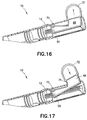
- the actuator 48 may be arranged to be non-linearly displaced. As shown in Figures 15-17 , the actuator 48 may be formed to pivot about a fulcrum 70. With the actuator 48 pivoting outwardly from the medical injector 10 about the fulcrum 70, the engagement portion 50 is caused to be displaced proximally. Conversely, inward pivoting of the actuator 48 about the fulcrum 70 causes distal displacement of the engagement portion 50. The engagement portion 50 coacts with the plunger 12 in the same manner as described above.
- the medical injector 10 is shown in a pre-use state.
- a grip ring or pad 72 may be provided which extends radially outwardly from the medical injector 10 to facilitate displacement of the actuator 48.
- the actuator 48 is pivoted to a ready state as shown in Figure 17 .
- the actuator 48 is pivoted inwardly from the ready state, as shown by the arrow in Figure 17 .
- the size of the dose may be fixed with the actuator 48 being pivotable by limiting the range of rotation of the actuator 48.
- a portion 74 of the medical injector 10 may be configured to limit the range of rotation of the actuator 48, particularly outward rotation, such limited range corresponding to the ready state.
- the plunger 12 is substantially flat.
- the plungers are substantially cylindrical.
- the plunger 142 is substantially cylindrical and the ratchet teeth extend circumferentially around the plunger 142.
- the orientation of the plunger is not critical, thereby easing assembly of the device.
- a pointer or indicator flag 144 connected to the plunger 142 is visible to a user through indicating holes 146 to indicate the dosage.
- the pointer 144 engages an axial slot 148 in the actuator 150 to provide an alignment feature.
- Figure 20 illustrates a medical injector 152 according to another embodiment of the present invention
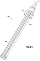
- figure 21 is a perspective view of a plunger usable with the medical injector 152
- figure 22 is a cross-sectional view of the medical injector 152.
- the medical injector 152 includes a body 154 having axial slots 156 therein, an actuator 158, a plunger slider or ring slider 160 with arms extending through the slots 156, and a mode selector 162.
- the ratchet teeth on the plunger are circumferentially discontinuous. Put another way, at least one portion of the plunger is axially free of ratchet teeth.
- Figure 21 illustrates another embodiment of a cylindrical plunger 164 in which the plunger 164 is frusto-cylindrical.
- the plunger 164 has a pair of flat sides 166.
- the plunger 164 also has a plurality of spaced-apart ratchet teeth 168 disposed along the length thereof.
- the plunger 164 also has a pair of ring slider connectors 170 disposed on the flat sides 166 and a mode selector connector 172 disposed at a proximal end of the plunger 164.
- the illustrated mode selector connector 172 is substantially square.
- the mode selector connector 172 may be triangular, rectangular, pentagonal, or hexagonal, or may have more sides.
- the mode selector 162 has a recess corresponding to the mode selector connector 172 to engage the mode selector connector 172. While in the illustrated embodiment, the male protrusion (mode selector connector 172) is disposed at the proximal end of the plunger 166 and the corresponding female recess is disposed on the distal end of the mode selector 162, one skilled in the art will appreciate that the male protrusion may be disposed on the distal end of the mode selector 162 and the corresponding female recess may be disposed on the proximal and of the plunger 166 without departing from the scope of the present invention.
- the mode selector 162 is rotatably disposed with respect to the actuator 158, and thereby, as described in greater detail below, provides an interface for a user to rotate the plunger 166.
- the ratchet teeth 168 of the plunger 166 engage the pawls 174 of the indexer 176 and the engagement pawls 178 of the actuator 158.
- the plunger 164 is rotatable with respect to the body 154. Accordingly, using the mode selector 162, a user can rotate the plunger 164 to an orientation in which the ratchet teeth 168 are disengaged from the pawls 174 and the engagement pawls 178, and the flat sides 166 are aligned with the pawls 174 and the engagement pawls 178, as shown in figure 22 .
- Such an alignment permits selective, free distal and proximal displacement of the plunger 164. This feature is useful, for example, for reconstituting a lyophilized medicament, which will be discussed in greater detail below.
- the ring slider connectors 170 disposed on the flat sides 166 of the plunger 164 selectively engage the arms 180 of the ring slider 160 that extend inwardly through the slots 156 of the body 154. For example, when a user rotates the mode selector 162 to disengage the ratchet teeth 168 from the pawls 174 and the engagement pawls 178, the ring slider connectors 170 rotate into engagement with the arms 180 of the ring slider 160. The user then can use the ring slider 162 to control displacement of the plunger 164.
- medical injector 152 also includes a pointer 182 for indicating the dosage, similar to the pointer 144.
- the plunger 164 is fixedly connected to the ring slider 160, which serves as a dosage indicator.
- the stopper 184 is disposed on the distal end of the plunger 164 inside a cartridge 186 containing a diluent 188 therein.
- the medicament container 190 with a lyophilized medicament 192 disposed therein is connected to a distal end of the cartridge 186 with a double-ended needle 194 communicating between interior of the medicament container 190 and the cartridge 186.
- the user After the user rotates the mode selector 162 to disengage the ratchet teeth 168 from the pawls 174 and the engagement pawls 178, the user distally slides the ring slider 160, thereby distally displacing the plunger 164 and the stopper 184, and expelling the diluent 188 into the medicament container 190. Subsequent to the reconstitution of the lyophilized medicament 192, the user proximally slides the ring slider 160, thereby proximally displacing the plunger 164 and the stopper 184, and drawing the reconstituted medicament into the cartridge 186.
- the user disconnects the medicament container 190 and rotates the mode selector 162 to reengage the ratchet teeth 168 with the pawls 174 and the engagement pawls 178.
- the reconstituted medicament can be injected as described above.
- FIG 24 is a perspective view of the plunger 194 in accordance with another embodiment of the present invention in which a user may select one of a plurality of predetermined ratchet spacings.
- the plunger 194 has two sides with and 196 and 198 with respective pluralities of spaced-apart ratchet teeth 200 and 202 disposed along the length thereof.
- the distance between ratchet teeth 200 is shown as D 1 and the distance between ratchet teeth 202 is shown as D 2 , which is greater than D 1 .
- the plunger 194 is rotatable with respect to the body 154 and the actuator 158 so that a user can select a desired spacing between ratchet teeth to engage the pawls 174 and the engagement pawls 178.
- the mode selector 162 and the actuator 158 have demarcations corresponding to the various spacings of the ratchet teeth.
- the plunger 194 also has a flat side 204 so that the user can rotate the plunger 194 to an orientation in which the ratchet teeth 168 are disengaged from the pawls 174 and the engagement pawls 178, and the flat side 204 is aligned with the pawls 174 and the engagement pawls 178.
- the plunger 194 can also be employed to reconstitute a lyophilized medicament.
- the plunger 194 is illustrated as having two sides with respective pluralities of spaced-apart ratchet teeth, one skilled in the art will appreciate that the plunger 194 may have 3, 4, 5, 6, 7, 8, 9, 10, or more sides with respective pluralities of differently-spaced-apart ratchet teeth to provide a greater selection for a user without departing from the scope of the present invention.
- the pawls 174 and the engagement pawls 178 are illustrated as being opposing pairs, a single pawl 174 and a single engagement pawl 178 may be employed to accommodate a greater number of sides with differently spaced ratchet teeth on the plunger 194 without departing from the scope of the present invention.
Abstract
Description
- This invention relates to displaceable medical injector plungers and, more particularly, to ratcheting, rotatable medical injector plungers.
- Medical injectors are well known in the art, including syringes and pen injectors. Medical injectors typically include a plunger for advancing one or more stoppers in delivering a medicament during an injection. Although it is known in the prior art to provide syringe plungers with teeth or other features to prevent retraction and re-use after an initial injection, syringe plungers are typically actuated through direct application of linear force. Dose size is a direct function of plunger displacement. It may be difficult to control linear displacement of the plunger, thus resulting in difficulty over control of dose size.
- As for pen injectors, a lead screw or rotating plunger is provided which is mechanically coupled to a dose-setting knob or other actuator through a series of mechanical connections. The typical pen injector mechanism is fairly complex and consists of multiple cooperating parts. For costs reasons and simplicity of use, a minimum number of working parts is desired.
- Accordingly, it is an aspect of the present invention to provide a plunger for a medical injector which may be controllably advanced with a minimum number of cooperating parts.
- The foregoing and/or other aspects of the present invention are achieved by providing a medical injector including a body having a distal end and a proximal end, and a displaceable plunger disposed in the body. The plunger includes a plurality of spaced-apart ratchet teeth disposed along the length thereof. At least one indexer is provided and is formed to engage the plunger, wherein the indexer is configured to allow the plunger to displace distally toward a distal end of the body but not proximally toward a proximal end of the body. The medical injector also includes an actuator having an engagement portion formed to engage one or more of the ratchet teeth. The actuator is displaceable to a ready state, the engagement portion being displaced proximally relative to the plunger with the actuator being displaced to the ready state. The indexer prevents proximal movement of the plunger thereby allowing the engagement portion to bypass one or more of the ratchet teeth with the actuator being displaced to the ready state. In addition, the actuator is displaceable from the ready state to cause actuation of the medical injector. The displacement from the ready state causes distal displacement of the engagement portion with the engagement portion engaging one or more of the ratchet teeth and causing distal displacement of the plunger with the engagement portion. The plunger is slidably displaceable relative to the body, and rotatable relative to the body to selectively engage and disengage ratchet teeth engaged with the indexer and the actuator.
- The foregoing and/or other aspects of the present invention are also achieved by providing a medical injector including a body having a distal end and a proximal end, and a plunger displaceably disposed in the body. The plunger includes a plurality of spaced-apart ratchet teeth disposed along the length thereof. The plunger selectively displaces a stopper to dispense a medicament from said medical injector. The medical injector also includes an indexer disposed within the body to engage the plunger to permit distal displacement of the plunger and substantially prevent proximal displacement of the plunger, and an actuator having an engagement portion to engage the plunger to permit proximal displacement of the actuator relative to the plunger and substantially prevent distal displacement of the actuator relative to the plunger. Upon proximal displacement of the actuator relative to the body to a ready state, one or more of the ratchet teeth bypass the engagement portion to proximally displace the actuator relative to the plunger. Upon distal displacement of the actuator relative to the body from the ready state, the actuator engages one or more of the ratchet teeth to distally displace the plunger relative to the indexer to distally displace the stopper to dispense medicament from the medical injector. The plunger is slidably displaceable relative to the body, and rotatable relative to the body to selectively engage and disengage ratchet teeth engaged with the indexer and the actuator.
- The foregoing and/or other aspects of the present invention are also achieved by providing a medical injector including a body having a distal end and a proximal end, and a plunger displaceably disposed in the body. The plunger includes a plurality of spaced-apart ratchet teeth disposed along the length thereof. The plunger selectively displaces a stopper to dispense a medicament from said medical injector. The medical injector also includes an indexer disposed within the body to engage the plunger to permit distal displacement of the plunger and substantially prevent proximal displacement of the plunger. The medical injector additionally includes actuating means for actuating the medical device, the actuating means having engagement means for engaging the plunger to permit proximal displacement of the actuating means relative to the plunger and substantially prevent distal displacement of the actuating means relative to the plunger. Upon proximal displacement of the actuating means relative to the body to a ready state, one or more of the ratchet teeth bypass the engagement means to proximally displace the actuating means relative to the plunger. Upon distal displacement of the actuating means relative to the body from the ready state, the actuating means engages one or more of the ratchet teeth to distally displace the plunger relative to the indexer to distally displace the stopper to dispense medicament from the medical injector. The plunger is rotatable relative to the body to selectively engage and disengage ratchet teeth engaged with the indexer and the actuator means.
- The foregoing and/or other aspects of the present invention are also achieved by providing a method of reconstituting a lyophilized medicament using a medical injector having a body with a plunger disposed therein. The method includes the operations of connecting a medicament container containing the lyophilized medicament to an end of the body so that a double ended needle communicates between the medicament container and a diluent containing cartridge disposed within the body, rotating the plunger to disengage ratchet teeth on the plunger from the body, displacing the plunger to eject diluent into the medicament container, displacing the plunger to draw reconstituted medicament into the cartridge, and rotating the plunger to engage the ratchet teeth of the plunger with the body.
- Additional and/or other aspects and advantages of the present invention will be set forth in part in the description that follows and, in part, will be apparent from the description, or may be learned by practice of the invention.
-
- The above and/or other aspects and advantages of embodiments of the invention will become apparent and more readily appreciated from the following detailed description, taken in conjunction with the accompanying drawings, in which
-
Figure 1 is a perspective view of a medical injector in accordance with an embodiment of present the invention; -
Figure 2 is partial perspective view of a plunger useable with the injector ofFigure 1 ; -
Figure 3 is a partial cross-sectional view taken along line 3-3 ofFigure 2 ; -
Figures 4-6 are perspective partial cross-sectional views illustrating operation of the medical injector ofFigure 1 ; -
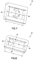
Figures 7 and 8 are perspective views respectively illustrating two rockers useable with the injector ofFigure 1 ; -
Figures 9-11 are perspective partial cross-sectional views illustrating operation of a medical injector in accordance with an embodiment of the present invention using the rocker ofFigure 7 ; -
Figures 12 and 13 are perspective partial cross-sectional views illustrating the use of a multi-link rocker in accordance with an embodiment of the present invention; -
Figure 14 shows a dose counter useable with an embodiment of the present invention; -
Figure 15 is a partial perspective view of a pivotable actuator useable with the plunger ofFigure 2 ; -
Figures 16 and 17 are perspective partial cross-sectional views illustrating use of the pivotable actuator ofFigure 15 , -
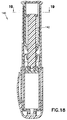
Figure 18 is a cross-sectional view of a medical injector in accordance with another embodiment of the present invention; -
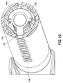
Figure 19 is a perspective cross-sectional view of the medical injector ofFigure 18 taken along line 19-19 ofFigure 18 ; -
Figure 20 is a perspective view of a medical injector according to another embodiment of the present invention; -
Figure 21 is a perspective view of a plunger useable with the medical injector ofFigure 20 ; -
Figure 22 is a cross-sectional view of the medical injector ofFigure 21 taken along line 22-22 ofFigure 21 ; -
Figure 23 is a perspective cross-sectional view illustrating operation of the medical injector ofFigure 21 ; and -
Figure 24 is a perspective view of another embodiment of a plunger useable with the medical injector ofFigure 20 . - Reference will now be made in detail to embodiments of the present invention, examples of which are illustrated in the accompanying drawings, wherein like reference numerals refer to the like elements throughout. The embodiments described herein exemplify, but do not limit, the present invention by referring to the drawings. As will be understood by one skilled in the art, terms such as up, down, bottom, and top are relative, and are employed to aid illustration, but are not limiting.
- With reference to the figures, a
medical injector 10 is shown having aratchetable plunger 12 provided therewith. As will be appreciated by those skilled in the art, themedical injector 10 may be of various forms, including being a syringe or pen injector. In accordance with an embodiment of the present invention, themedical injector 10 is particularly well-suited for administering at least one fixed dose, and is even better suited for administering a series of fixed doses. Themedical injector 10 may be configured in any way known to be compatible with theplunger 12 as described herein. Themedical injector 10 may include areservoir 14 for accommodating an injectable medicament, which may be a drug cartridge, or which may be formed directly in themedical injector 10. Thereservoir 14 may have one ormore stoppers 16 associated therewith as known in the art. Themedical injector 10 may also be provided with aneedle 18 for injection which may be removably attached or affixed to themedical injector 10 such as in a "staked" arrangement. - The
plunger 12 is elongated and generally flat. Aplurality of spaced-apart ratchetteeth 20 are disposed along the length of theplunger 12. In a preferred arrangement, theplunger 12 includes a plate-shapedbody 22 having opposing first and second faces 24, 26. Theratchet teeth 20 are disposed on thefirst face 24 and, in a further preferred arrangement, also on thesecond face 26. Preferably, theratchet teeth 20 on the first and second faces 24, 26 are axially aligned along the length of theplunger 12. - The
ratchet teeth 20 are configured to permit unidirectional movement of theplunger 12. Particularly, with reference toFigure 3 , theratchet teeth 20 are preferably saw-tooth shaped having a rampedsurface 28 and ashoulder stop 30. As shown inFigure 3 , the ramped surfaces 28 of theratchet teeth 20 on both the first andsecond surfaces - The
plunger 12 may also have one ormore rails 27 extending from thefirst face 24 and/or thesecond face 26. Therails 27 may be formed to slide through one or more corresponding shape-mating slots formed in themedical injector 10. Therails 27 may provide stability during use, particularly during translation of theplunger 12. - With reference to
Figures 4-6 , theplunger 12 is disposed in abody 32 of themedical injector 10. Thebody 32 includes adistal end 34, located to be directed toward a patient during an injection, and aproximal end 36, located to be away from a patient during an injection (Figure 1 ). During use, themedical injector 10 is configured to permit theplunger 12 to move unidirectionally therein in a distal direction toward thedistal end 34, but not in a proximal direction toward theproximal end 36. To facilitate such unidirectional movement, at least oneindexer 38 is provided formed to engage theplunger 12. Theindexer 38 is configured to allow theplunger 12 to displace distally toward thedistal end 34 of thebody 32 but not proximally toward theproximal end 36 of thebody 32. - The
indexer 38 includes adeflectable pawl 40 which, as shown schematically inFigure 3 , includes a rampedengagement surface 42 and an outward facingstop surface 44. Theindexer 38 is outwardly deflectable to permit theengagement surface 42 to ascend the rampedsurface 28 of an individual of theratchet teeth 20 with theplunger 12 moving distally relative thereto. With sufficient distal movement, theindexer 38 bypasses theratchet teeth 12, and under inherent resilience of theindexer 38, snaps inwardly such that thestop surface 44 is aligned with theshoulder stop 30. Preferably, thestop surface 44 is formed to be generally parallel to theshoulder stop 30. With rearward (proximal) movement of theplunger 12, theshoulder stop 30 and thestop surface 44 interferingly engage thus preventing proximal movement of theplunger 12. In a preferred embodiment, a pair of theindexers 38 are provided so as to act against theratchet teeth 20 located on both the first and second faces 24, 26, as shown inFigures 4-6 . It is further preferred that a pair of theindexers 38 be provided which are axially aligned thus providing a pinching effect to theplunger 12. This pinching effect may provide a stable holding force for theplunger 12. - The
indexer 38 may be formed to be deflectable through inherent resilience, such as through material selection (e.g., being formed of a thermoplastic). In addition, or alternatively, theindexer 38 may include acantilevered arm 46 which permits deflection of the associatedpawl 40. Theindexer 38 is formed to have a natural, unbiased state as shown inFigures 4-6 , where theindexer 38 is positioned to act against theshoulder stop 30 of theratchet teeth 20. The cantileveredarm 46 is formed with sufficient internal memory to provide the unbiased state for theindexer 38. - The
medical injector 10 also includes anactuator 48 having anengagement portion 50 formed to engage one or more of theratchet teeth 20. Theengagement portion 50 preferably includes anengagement pawl 52 having a rampedengagement surface 54 and an outward facingstop surface 56 configured like thepawl 40 described above. Preferably, two of theengagement portions 50 are provided located to engage theratchet teeth 20 located on the first and second faces 24, 26. - With reference to
Figure 4 , theplunger 12 is positioned to engage one of thestoppers 16. To cause actuation of themedical injector 10, as shown inFigure 5 , theactuator 48 is moved to a ready state, with theengagement portion 50 moving proximally. Theindexer 38 prevents proximal movement of theplunger 12, thus allowing theactuator 48 to move proximally relative to theplunger 12. With theplunger 12 being held stationary, and theengagement portion 50 moving proximally relative to theplunger 12, theengagement portion 50 bypasses one or more of theratchet teeth 20. Theactuator 48 is displaced sufficiently to achieve a ready state. - For actuation of the
medical injector 10, theactuator 48 is displaced from the ready state with distal movement of theengagement portion 50. Theengagement portion 50 engages one or more of theratchet teeth 20, particularly with interfering engagement between theshoulder stop 30 and thestop surface 56. In particular, theengagement portion 50 engages the nextdistal ratchet tooth 20. Distal movement of theengagement portion 50 causes theplunger 12 to move distally therewith. Distal movement of theplunger 12, in turn, causes distal advancement of thestopper 16 in causing an injection to be administered. Theratchet teeth 20 are able to bypass theindexer 38 in the distal direction. - The size of a dose to be administered by the
medical injector 10 is a function of the spacing between theratchet teeth 20 and/or the amount of proximal displacement of theengagement portion 50 relative to theratchet teeth 20 with theactuator 48 moving to a ready state. To create a fixed dose, one ormore keys 58 may be defined on themedical injector 10 and/or theactuator 48 which are formed to nest within and slide alongcorresponding channels 60 formed in themedical injector 10 and/or theactuator 48. As shown inFigures 4-6 , it is preferred that thekeys 58 be formed on theactuator 48 and thechannels 60 be formed in themedical injector 10. With reference toFigure 4 , thekeys 58 are at the distal end of thechannel 60, prior to use. With proximal displacement of theactuator 48, thekeys 58 are proximally advanced in thechannels 60 to a proximal-most position corresponding to the ready state of theactuator 48. The length of the travel of thekeys 58 in thechannels 60 restricts the range of movement of theactuator 48 in defining the size of the dose administrable by themedical injector 10. As shown inFigures 5 and 6 , thekeys 58 are advanced distally with theactuator 48 during use to a distal-most position. - The
actuator 48 shown inFigures 4-6 is a linear slide actuator which applies force directly to theplunger 12. As will be appreciated by those skilled in the art, theactuator 48 may be of various configurations. With reference toFigures 7-8 , theactuator 48 may include arocker 62 pivotally mounted thereto. Therocker 62 is frame-shaped, having afirst end 64 for pivotal mounting to theactuator 48 and a second opposingend 66 for pivotally mounting to themedical injector 10. Theengagement portion 50 is located between the first and second ends 64, 66. As shown inFigures 7 and 8 , two of theengagement portions 50 may be provided to coact with theratchet teeth 20 being located on the first and second faces 24, 26. - It is noted that the spacing between the first and second ends 64, 66 affects force transmission from the
actuator 48 to theplunger 12 particularly in the generation of torque. The spacing L between the first and second ends 64, 66, as well as the spacing S1, S2 of theengagement portion 50 from the first and second ends 64, 66, affects how torque is generated and transmitted to theplunger 12. - With reference to
Figure 9 , theactuator 48 is shown in an initial pre-use state with therocker 62 being inclined distally. With reference toFigure 10 , theactuator 48 has been advanced to the ready state with therocker 62 having been drawn proximally with rotation about thesecond end 66 so as to be inclined in a proximal direction. During this movement, theengagement portion 50 bypasses one or more of theratchet teeth 20 in the same manner as described above. As shown inFigure 11 , theactuator 48 is displaced from the ready state to cause actuation of themedical injector 10. With displacement of the actuator 48 from the ready state, therocker 62 is caused to advance distally about thesecond end 66 with theengagement portion 50 causing theplunger 12 to also advance distally. Dose size may be restricted both by the key 58/channel 60 arrangement described above and/or by the range of motion of therocker 62. - As will be appreciated by those skilled in the art, the
rocker 62 may be directly coupled to theactuator 48, as shown inFigures 9-11 . As will be appreciated by those skilled in the art, a multi-link arrangement may be used to couple therocker 62 to theactuator 48. With reference toFigures 12 and 13 , one ormore links 68 may be connected between therocker 62 and theactuator 48 to provide force for displacement thereof. Any arrangement of thelinks 68 may be utilized which transmits force from theactuator 48 to therocker 62. As shown inFigures 12 and 13 , two of the links 68 (68A, 68B) are utilized with thelink 68A being pivotally connected to theactuator 48 and pivotally connected to thelink 68B, and with thelink 68B being pivotally connected to thelink 68A and pivotally connected to therocker 62. Thelinks rocker 62. - With reference to
Figures 15-17 , theactuator 48 may be arranged to be non-linearly displaced. As shown inFigures 15-17 , theactuator 48 may be formed to pivot about afulcrum 70. With theactuator 48 pivoting outwardly from themedical injector 10 about thefulcrum 70, theengagement portion 50 is caused to be displaced proximally. Conversely, inward pivoting of theactuator 48 about the fulcrum 70 causes distal displacement of theengagement portion 50. Theengagement portion 50 coacts with theplunger 12 in the same manner as described above. - With reference to
Figures 15 and16 , themedical injector 10 is shown in a pre-use state. To facilitate handling of theactuator 48, a grip ring orpad 72 may be provided which extends radially outwardly from themedical injector 10 to facilitate displacement of theactuator 48. To prepare for use, as shown by the arrow inFigure 16 , theactuator 48 is pivoted to a ready state as shown inFigure 17 . To cause actuation of themedical injector 10, theactuator 48 is pivoted inwardly from the ready state, as shown by the arrow inFigure 17 . - The size of the dose may be fixed with the
actuator 48 being pivotable by limiting the range of rotation of theactuator 48. Aportion 74 of themedical injector 10 may be configured to limit the range of rotation of theactuator 48, particularly outward rotation, such limited range corresponding to the ready state. - In the above-described embodiments, the
plunger 12 is substantially flat. In contrast, in the following embodiments, the plungers are substantially cylindrical. For example, in themedical injector 140 shown infigures 18 and19 , theplunger 142 is substantially cylindrical and the ratchet teeth extend circumferentially around theplunger 142. In such an embodiment, the orientation of the plunger is not critical, thereby easing assembly of the device. In addition, as shown infigures 18 and19 , a pointer orindicator flag 144 connected to theplunger 142 is visible to a user through indicatingholes 146 to indicate the dosage. Thepointer 144 engages anaxial slot 148 in theactuator 150 to provide an alignment feature. -
Figure 20 illustrates amedical injector 152 according to another embodiment of the present invention,figure 21 is a perspective view of a plunger usable with themedical injector 152, andfigure 22 is a cross-sectional view of themedical injector 152. As shown infigures 20 and22 , themedical injector 152 includes abody 154 havingaxial slots 156 therein, anactuator 158, a plunger slider orring slider 160 with arms extending through theslots 156, and amode selector 162. According to one embodiment, the ratchet teeth on the plunger are circumferentially discontinuous. Put another way, at least one portion of the plunger is axially free of ratchet teeth.Figure 21 illustrates another embodiment of acylindrical plunger 164 in which theplunger 164 is frusto-cylindrical. In other words, theplunger 164 has a pair offlat sides 166. As with theplunger 12, theplunger 164 also has a plurality of spaced-apart ratchetteeth 168 disposed along the length thereof. Theplunger 164 also has a pair ofring slider connectors 170 disposed on theflat sides 166 and amode selector connector 172 disposed at a proximal end of theplunger 164. The illustratedmode selector connector 172 is substantially square. One skilled in the art will appreciate that other shapes may be used without departing from the scope of the present invention. For example, themode selector connector 172 may be triangular, rectangular, pentagonal, or hexagonal, or may have more sides. - The
mode selector 162 has a recess corresponding to themode selector connector 172 to engage themode selector connector 172. While in the illustrated embodiment, the male protrusion (mode selector connector 172) is disposed at the proximal end of theplunger 166 and the corresponding female recess is disposed on the distal end of themode selector 162, one skilled in the art will appreciate that the male protrusion may be disposed on the distal end of themode selector 162 and the corresponding female recess may be disposed on the proximal and of theplunger 166 without departing from the scope of the present invention. Themode selector 162 is rotatably disposed with respect to theactuator 158, and thereby, as described in greater detail below, provides an interface for a user to rotate theplunger 166. - Similar to the embodiments described previously, in one orientation, the
ratchet teeth 168 of theplunger 166 engage thepawls 174 of theindexer 176 and theengagement pawls 178 of theactuator 158. But because of the design of the plunger 164 (including the flat sides 166), theplunger 164 is rotatable with respect to thebody 154. Accordingly, using themode selector 162, a user can rotate theplunger 164 to an orientation in which theratchet teeth 168 are disengaged from thepawls 174 and theengagement pawls 178, and theflat sides 166 are aligned with thepawls 174 and theengagement pawls 178, as shown infigure 22 . Such an alignment permits selective, free distal and proximal displacement of theplunger 164. This feature is useful, for example, for reconstituting a lyophilized medicament, which will be discussed in greater detail below. - According to one embodiment, the
ring slider connectors 170 disposed on theflat sides 166 of theplunger 164 selectively engage thearms 180 of thering slider 160 that extend inwardly through theslots 156 of thebody 154. For example, when a user rotates themode selector 162 to disengage theratchet teeth 168 from thepawls 174 and theengagement pawls 178, thering slider connectors 170 rotate into engagement with thearms 180 of thering slider 160. The user then can use thering slider 162 to control displacement of theplunger 164. - As shown in
figure 22 ,medical injector 152 also includes apointer 182 for indicating the dosage, similar to thepointer 144. According to another embodiment, in which theaxial slots 156 are circumferentially enlarged to accommodate rotation of thering slider 160, theplunger 164 is fixedly connected to thering slider 160, which serves as a dosage indicator. - Reconstitution of a lyophilized medicament will now be described with reference to
figure 23 . Thestopper 184 is disposed on the distal end of theplunger 164 inside acartridge 186 containing a diluent 188 therein. Themedicament container 190 with alyophilized medicament 192 disposed therein is connected to a distal end of thecartridge 186 with a double-endedneedle 194 communicating between interior of themedicament container 190 and thecartridge 186. After the user rotates themode selector 162 to disengage theratchet teeth 168 from thepawls 174 and theengagement pawls 178, the user distally slides thering slider 160, thereby distally displacing theplunger 164 and thestopper 184, and expelling the diluent 188 into themedicament container 190. Subsequent to the reconstitution of thelyophilized medicament 192, the user proximally slides thering slider 160, thereby proximally displacing theplunger 164 and thestopper 184, and drawing the reconstituted medicament into thecartridge 186. Thereafter, the user disconnects themedicament container 190 and rotates themode selector 162 to reengage theratchet teeth 168 with thepawls 174 and theengagement pawls 178. At this point, the reconstituted medicament can be injected as described above. - In the medical injector employing a ratchet plunger similar to those described above, discrete dosage settings are determined by the pitch of (or spacing between) the ratchets.
Figure 24 is a perspective view of theplunger 194 in accordance with another embodiment of the present invention in which a user may select one of a plurality of predetermined ratchet spacings. As shown infigure 24 , theplunger 194 has two sides with and 196 and 198 with respective pluralities of spaced-apart ratchetteeth ratchet teeth 200 is shown as D1 and the distance betweenratchet teeth 202 is shown as D2, which is greater than D1. Theplunger 194 is rotatable with respect to thebody 154 and theactuator 158 so that a user can select a desired spacing between ratchet teeth to engage thepawls 174 and theengagement pawls 178. According to one embodiment, themode selector 162 and theactuator 158 have demarcations corresponding to the various spacings of the ratchet teeth. - According to one embodiment, the
plunger 194 also has aflat side 204 so that the user can rotate theplunger 194 to an orientation in which theratchet teeth 168 are disengaged from thepawls 174 and theengagement pawls 178, and theflat side 204 is aligned with thepawls 174 and theengagement pawls 178. Thus, theplunger 194 can also be employed to reconstitute a lyophilized medicament. - In addition, although the
plunger 194 is illustrated as having two sides with respective pluralities of spaced-apart ratchet teeth, one skilled in the art will appreciate that theplunger 194 may have 3, 4, 5, 6, 7, 8, 9, 10, or more sides with respective pluralities of differently-spaced-apart ratchet teeth to provide a greater selection for a user without departing from the scope of the present invention. Additionally, although thepawls 174 and theengagement pawls 178 are illustrated as being opposing pairs, asingle pawl 174 and asingle engagement pawl 178 may be employed to accommodate a greater number of sides with differently spaced ratchet teeth on theplunger 194 without departing from the scope of the present invention. - Although only a few embodiments of the present invention have been shown and described, the present invention is not limited to the described embodiments. Instead, it will be appreciated by those skilled in the art that changes may be made to these embodiments without departing from the principles and spirit of the invention, the scope of which is defined by the claims and their equivalents.
Claims (7)
- A medical injector (152), comprising:a body ( 154) having a distal end and a proximal end;a displaceable plunger (194) disposed in the body, the plunger having a plurality of spaced-apart ratchet teeth (200, 202) disposed along the length thereof;at least one indexer (176) formed to engage the plunger, wherein the indexer is configured to allow the plunger to displace distally toward the distal end of the body but not proximally toward the proximal end of the body; andan actuator (158) having an engagement portion formed to engage one or more of the ratchet teeth, wherein the actuator is displaceable to a ready state, the engagement portion being displaced proximally relative to the plunger upon the actuator being displaced to the ready state, the indexer preventing proximal movement of the plunger thereby allowing the engagement portion to bypass one or more of the ratchet teeth upon the actuator being displaced to the ready state, and wherein the actuator is displaceable from the ready state to cause actuation of the medical injector, the displacement from the ready state causing distal displacement of the engagement portion with the engagement portion engaging one or more of the ratchet teeth and causing distal displacement of the plunger;characterized in that:the plunger is slidably displaceable relative to the body, and rotatable relative to the body to selectively engage and disengage ratchet teeth engaged with the indexer and the actuator;the plunger comprises a plurality of sides with respective pluralities of spaced-apart ratchet teeth (200, 202) disposed along the length thereof;at least two of the sides have different spacing between the ratchet teeth; andthe plunger is rotatable relative to the body to select a side with a desired ratchet teeth spacing to engage the indexer and the actuator.
- The medical injector according to claim 1, wherein the plunger comprises at least one flat side (204) alignable with the indexer and the actuator, to disengage ratchet teeth from the indexer and the actuator.
- The medical injector according to claim 1, further comprising a mode selector rotatable relative to the actuator and the body and being connected to plunger to control rotation of the plunger relative to the body.
- The medical injector according to claim 3, wherein the mode selector comprises one of a protrusion and a recess having a shape corresponding to the protrusion, and the plunger comprises the remaining one of the protrusion and the recess having a shape corresponding to the protrusion.
- The medical injector according to claim 1, wherein the plunger comprises at least one flat side alignable with the indexer and the actuator, to disengage the ratchet teeth from the indexer and the actuator.
- The medical injector according to claim 1, further comprising a plunger slider disposed on an exterior of the body to be operable by a user;
wherein the body comprises at least one axial slot and the plunger slider has an arm extending through the axial slot to engage the plunger, the plunger slider arm being slidable along the axial slot. - The medical injector according to claim 6, wherein the plunger is rotatable relative to the plunger slider to selectively engage and disengage the plunger slider.
Priority Applications (3)
| Application Number | Priority Date | Filing Date | Title |
|---|---|---|---|
| EP16158107.9A EP3050587B1 (en) | 2011-03-17 | 2011-03-17 | Medical injector with rotatable ratcheting plunger |
| DK16158107.9T DK3050587T3 (en) | 2011-03-17 | 2011-03-17 | Medical injector with rotatable peeling piston |
| ES16158107.9T ES2643562T3 (en) | 2011-03-17 | 2011-03-17 | Medical injector with rotating ratchet plunger |
Applications Claiming Priority (3)
| Application Number | Priority Date | Filing Date | Title |
|---|---|---|---|
| PCT/US2011/000492 WO2012125132A1 (en) | 2011-03-17 | 2011-03-17 | Medical injector with rotatable ratcheting plunger |
| EP16158107.9A EP3050587B1 (en) | 2011-03-17 | 2011-03-17 | Medical injector with rotatable ratcheting plunger |
| EP11861021.1A EP2686046B1 (en) | 2011-03-17 | 2011-03-17 | Medical injector with rotatable ratcheting plunger |
Related Parent Applications (2)
| Application Number | Title | Priority Date | Filing Date |
|---|---|---|---|
| EP11861021.1A Division EP2686046B1 (en) | 2011-03-17 | 2011-03-17 | Medical injector with rotatable ratcheting plunger |
| EP11861021.1A Division-Into EP2686046B1 (en) | 2011-03-17 | 2011-03-17 | Medical injector with rotatable ratcheting plunger |
Publications (2)
| Publication Number | Publication Date |
|---|---|
| EP3050587A1 true EP3050587A1 (en) | 2016-08-03 |
| EP3050587B1 EP3050587B1 (en) | 2017-07-12 |
Family
ID=46831000
Family Applications (3)
| Application Number | Title | Priority Date | Filing Date |
|---|---|---|---|
| EP11861021.1A Active EP2686046B1 (en) | 2011-03-17 | 2011-03-17 | Medical injector with rotatable ratcheting plunger |
| EP16158107.9A Active EP3050587B1 (en) | 2011-03-17 | 2011-03-17 | Medical injector with rotatable ratcheting plunger |
| EP17178475.4A Active EP3251714B1 (en) | 2011-03-17 | 2011-03-17 | Medical injector with rotatable ratcheting plunger |
Family Applications Before (1)
| Application Number | Title | Priority Date | Filing Date |
|---|---|---|---|
| EP11861021.1A Active EP2686046B1 (en) | 2011-03-17 | 2011-03-17 | Medical injector with rotatable ratcheting plunger |
Family Applications After (1)
| Application Number | Title | Priority Date | Filing Date |
|---|---|---|---|
| EP17178475.4A Active EP3251714B1 (en) | 2011-03-17 | 2011-03-17 | Medical injector with rotatable ratcheting plunger |
Country Status (6)
| Country | Link |
|---|---|
| EP (3) | EP2686046B1 (en) |
| JP (1) | JP5866385B2 (en) |
| CN (3) | CN109730928B (en) |
| DK (3) | DK3251714T3 (en) |
| ES (3) | ES2717598T3 (en) |
| WO (1) | WO2012125132A1 (en) |
Families Citing this family (11)
| Publication number | Priority date | Publication date | Assignee | Title |
|---|---|---|---|---|
| CA2906253C (en) * | 2013-03-14 | 2018-04-24 | Norton Healthcare Limited | Dispensing mechanism for a medical device |
| JP6109352B2 (en) * | 2013-03-14 | 2017-04-05 | ノートン・ヘルスケア・リミテッド | Dosing mechanism for medical devices |
| GB2511806A (en) | 2013-03-14 | 2014-09-17 | Norton Healthcare Ltd | Dispensing mechanism for a medical device |
| US10314980B2 (en) | 2013-03-14 | 2019-06-11 | Norton Healthcare Limited | Dispensing mechanism for a medical device |
| GB2529621B (en) * | 2014-08-21 | 2016-12-07 | Owen Mumford Ltd | Safety syringe |
| JP6917893B2 (en) * | 2014-12-22 | 2021-08-11 | ノボ・ノルデイスク・エー/エス | Injection device with removable cap |
| EP3355969B1 (en) * | 2015-10-01 | 2019-11-20 | Novo Nordisk A/S | Piston washer assembly, method of assembly and drug delivery device incorporating such piston washer assembly |
| US10751476B2 (en) * | 2016-06-09 | 2020-08-25 | Becton, Dickinson And Company | Actuator assembly for drug delivery system |
| US20200046906A1 (en) * | 2017-02-24 | 2020-02-13 | Cc Biotechnology Corporation | Injection Device Having a Capability of Controlling Injection Dose |
| JP7344535B2 (en) * | 2019-05-20 | 2023-09-14 | 株式会社タスク | Plunger for metered dose syringe and metered dose syringe |
| CA3103497A1 (en) * | 2020-12-22 | 2022-06-22 | Duoject Medical Systems Inc. | Secure reconstitution device |
Citations (6)
| Publication number | Priority date | Publication date | Assignee | Title |
|---|---|---|---|---|
| EP0272035A2 (en) * | 1986-12-16 | 1988-06-22 | National Research Development Corporation | Injection device |
| US5224936A (en) * | 1992-10-15 | 1993-07-06 | Brian Gallagher | Automatic self-protecting hypodermic needle assembly |
| WO1994006494A1 (en) * | 1992-09-19 | 1994-03-31 | Hypoguard (Uk) Limited | Syringe with incrementally actuated plunger |
| WO1994013339A1 (en) * | 1992-12-14 | 1994-06-23 | Mallinckrodt Medical, Inc. | Mechanism preventing rearward movement of piston syringe |
| WO2003020347A2 (en) * | 2001-03-27 | 2003-03-13 | Eli Lilly And Company | Medication dispensing apparatus configured for pull to set dose and push to inject set dose functionality |
| WO2010033770A2 (en) * | 2008-09-18 | 2010-03-25 | Becton, Dickinson And Company | Medical injector with ratcheting plunger |
Family Cites Families (13)
| Publication number | Priority date | Publication date | Assignee | Title |
|---|---|---|---|---|
| JPS58168334U (en) * | 1982-05-07 | 1983-11-10 | カネウ科学有限会社 | Accurate dispensing device for different amounts |
| WO1993010839A1 (en) * | 1991-11-29 | 1993-06-10 | Novo Nordisk A/S | A pen-shaped syringe |
| DE4425763A1 (en) * | 1994-07-21 | 1996-01-25 | Braun Medical Ag | Device for advancing a piston displacement member |
| RU2060736C1 (en) * | 1994-12-09 | 1996-05-27 | Научно-учебно-производственное объединение ТОО "Мединфодент" | Stomatologic syringe |
| CN1224362A (en) * | 1996-05-09 | 1999-07-28 | 犹尼韦克股份有限公司 | Single-use syringe with aspirating mechanism |
| ATE275914T1 (en) * | 2000-02-16 | 2004-10-15 | Haselmeier S A R L | METHOD FOR RECONSTITUTING AN INJECTION FLUID AND INJECTION DEVICE FOR CARRYING OUT SUCH PROCESS |
| US6689101B2 (en) * | 2000-05-22 | 2004-02-10 | Pharmacia Ab | Medical arrangement |
| US20070232998A1 (en) * | 2004-10-25 | 2007-10-04 | Chang-Ming Yang | Injection Apparatus |
| ATE418351T1 (en) * | 2005-02-11 | 2009-01-15 | Novo Nordisk As | INJECTION DEVICE |
| DK1855742T3 (en) * | 2005-02-22 | 2009-04-20 | Tecpharma Licensing Ag | Dosage device for setting fine dosages |
| US7867197B2 (en) * | 2006-03-29 | 2011-01-11 | The General Hospital Corporation | Single-dose syringe driver |
| FR2903685B1 (en) * | 2006-07-13 | 2008-09-05 | Arkema France | PROCESS FOR OBTAINING 1,2-DICHLOROETHANE BY DIRECT CHLORINATION WITH DIRECT EVAPORATION CATALYST SEPARATION STEP AND INSTALLATION FOR CARRYING OUT SAID METHOD |
| EP2676692A1 (en) * | 2009-09-30 | 2013-12-25 | Sanofi-Aventis Deutschland GmbH | A mechanism for a drug delivery device |
-
2011
- 2011-03-17 CN CN201910200889.0A patent/CN109730928B/en active Active
- 2011-03-17 ES ES17178475T patent/ES2717598T3/en active Active
- 2011-03-17 ES ES16158107.9T patent/ES2643562T3/en active Active
- 2011-03-17 WO PCT/US2011/000492 patent/WO2012125132A1/en active Application Filing
- 2011-03-17 CN CN201610177393.2A patent/CN105854127B/en active Active
- 2011-03-17 DK DK17178475.4T patent/DK3251714T3/en active
- 2011-03-17 EP EP11861021.1A patent/EP2686046B1/en active Active
- 2011-03-17 JP JP2013558821A patent/JP5866385B2/en active Active
- 2011-03-17 DK DK16158107.9T patent/DK3050587T3/en active
- 2011-03-17 ES ES11861021T patent/ES2733932T3/en active Active
- 2011-03-17 DK DK11861021.1T patent/DK2686046T3/en active
- 2011-03-17 EP EP16158107.9A patent/EP3050587B1/en active Active
- 2011-03-17 CN CN201180070439.6A patent/CN103501843B/en active Active
- 2011-03-17 EP EP17178475.4A patent/EP3251714B1/en active Active
Patent Citations (6)
| Publication number | Priority date | Publication date | Assignee | Title |
|---|---|---|---|---|
| EP0272035A2 (en) * | 1986-12-16 | 1988-06-22 | National Research Development Corporation | Injection device |
| WO1994006494A1 (en) * | 1992-09-19 | 1994-03-31 | Hypoguard (Uk) Limited | Syringe with incrementally actuated plunger |
| US5224936A (en) * | 1992-10-15 | 1993-07-06 | Brian Gallagher | Automatic self-protecting hypodermic needle assembly |
| WO1994013339A1 (en) * | 1992-12-14 | 1994-06-23 | Mallinckrodt Medical, Inc. | Mechanism preventing rearward movement of piston syringe |
| WO2003020347A2 (en) * | 2001-03-27 | 2003-03-13 | Eli Lilly And Company | Medication dispensing apparatus configured for pull to set dose and push to inject set dose functionality |
| WO2010033770A2 (en) * | 2008-09-18 | 2010-03-25 | Becton, Dickinson And Company | Medical injector with ratcheting plunger |
Also Published As
| Publication number | Publication date |
|---|---|
| CN105854127B (en) | 2019-04-09 |
| CN103501843B (en) | 2016-08-17 |
| ES2733932T3 (en) | 2019-12-03 |
| JP2014513595A (en) | 2014-06-05 |
| CN109730928B (en) | 2022-08-30 |
| EP3251714A1 (en) | 2017-12-06 |
| ES2643562T3 (en) | 2017-11-23 |
| EP3251714B1 (en) | 2019-01-02 |
| DK3050587T3 (en) | 2017-10-23 |
| CN109730928A (en) | 2019-05-10 |
| CN105854127A (en) | 2016-08-17 |
| CN103501843A (en) | 2014-01-08 |
| WO2012125132A1 (en) | 2012-09-20 |
| EP2686046B1 (en) | 2019-05-01 |
| DK2686046T3 (en) | 2019-08-05 |
| EP3050587B1 (en) | 2017-07-12 |
| JP5866385B2 (en) | 2016-02-17 |
| DK3251714T3 (en) | 2019-04-08 |
| EP2686046A1 (en) | 2014-01-22 |
| EP2686046A4 (en) | 2015-09-02 |
| ES2717598T3 (en) | 2019-06-24 |
Similar Documents
| Publication | Publication Date | Title |
|---|---|---|
| US10143807B2 (en) | Medical injector with ratcheting plunger | |
| EP3251714B1 (en) | Medical injector with rotatable ratcheting plunger | |
| CN105517605A (en) | Injection device for selective fixed or variable dosing | |
| EP2686034B1 (en) | Medical injector with ratcheting plunger |
Legal Events
| Date | Code | Title | Description |
|---|---|---|---|
| PUAI | Public reference made under article 153(3) epc to a published international application that has entered the european phase |
Free format text: ORIGINAL CODE: 0009012 |
|
| AC | Divisional application: reference to earlier application |
Ref document number: 2686046 Country of ref document: EP Kind code of ref document: P |
|
| AK | Designated contracting states |
Kind code of ref document: A1 Designated state(s): AL AT BE BG CH CY CZ DE DK EE ES FI FR GB GR HR HU IE IS IT LI LT LU LV MC MK MT NL NO PL PT RO RS SE SI SK SM TR |
|
| 17P | Request for examination filed |
Effective date: 20161005 |
|
| RBV | Designated contracting states (corrected) |
Designated state(s): AL AT BE BG CH CY CZ DE DK EE ES FI FR GB GR HR HU IE IS IT LI LT LU LV MC MK MT NL NO PL PT RO RS SE SI SK SM TR |
|
| GRAP | Despatch of communication of intention to grant a patent |
Free format text: ORIGINAL CODE: EPIDOSNIGR1 |
|
| RAP1 | Party data changed (applicant data changed or rights of an application transferred) |
Owner name: BECTON, DICKINSON AND COMPANY |
|
| INTG | Intention to grant announced |
Effective date: 20161130 |
|
| GRAJ | Information related to disapproval of communication of intention to grant by the applicant or resumption of examination proceedings by the epo deleted |
Free format text: ORIGINAL CODE: EPIDOSDIGR1 |
|
| INTC | Intention to grant announced (deleted) | ||
| GRAR | Information related to intention to grant a patent recorded |
Free format text: ORIGINAL CODE: EPIDOSNIGR71 |
|
| GRAS | Grant fee paid |
Free format text: ORIGINAL CODE: EPIDOSNIGR3 |
|
| GRAA | (expected) grant |
Free format text: ORIGINAL CODE: 0009210 |
|
| AC | Divisional application: reference to earlier application |
Ref document number: 2686046 Country of ref document: EP Kind code of ref document: P |
|
| AK | Designated contracting states |
Kind code of ref document: B1 Designated state(s): AL AT BE BG CH CY CZ DE DK EE ES FI FR GB GR HR HU IE IS IT LI LT LU LV MC MK MT NL NO PL PT RO RS SE SI SK SM TR |
|
| INTG | Intention to grant announced |
Effective date: 20170602 |
|
| REG | Reference to a national code |
Ref country code: GB Ref legal event code: FG4D |
|
| REG | Reference to a national code |
Ref country code: CH Ref legal event code: EP |
|
| REG | Reference to a national code |
Ref country code: AT Ref legal event code: REF Ref document number: 907755 Country of ref document: AT Kind code of ref document: T Effective date: 20170715 |
|
| REG | Reference to a national code |
Ref country code: IE Ref legal event code: FG4D |
|
| REG | Reference to a national code |
Ref country code: DE Ref legal event code: R096 Ref document number: 602011039609 Country of ref document: DE |
|
| REG | Reference to a national code |
Ref country code: CH Ref legal event code: NV Representative=s name: ISLER AND PEDRAZZINI AG, CH |
|
| REG | Reference to a national code |
Ref country code: NL Ref legal event code: FP |
|
| REG | Reference to a national code |
Ref country code: SE Ref legal event code: TRGR |
|
| REG | Reference to a national code |
Ref country code: DK Ref legal event code: T3 Effective date: 20171019 |
|
| REG | Reference to a national code |
Ref country code: ES Ref legal event code: FG2A Ref document number: 2643562 Country of ref document: ES Kind code of ref document: T3 Effective date: 20171123 |
|
| REG | Reference to a national code |
Ref country code: LT Ref legal event code: MG4D |
|
| REG | Reference to a national code |
Ref country code: AT Ref legal event code: MK05 Ref document number: 907755 Country of ref document: AT Kind code of ref document: T Effective date: 20170712 |
|
| PG25 | Lapsed in a contracting state [announced via postgrant information from national office to epo] |
Ref country code: NO Free format text: LAPSE BECAUSE OF FAILURE TO SUBMIT A TRANSLATION OF THE DESCRIPTION OR TO PAY THE FEE WITHIN THE PRESCRIBED TIME-LIMIT Effective date: 20171012 Ref country code: AT Free format text: LAPSE BECAUSE OF FAILURE TO SUBMIT A TRANSLATION OF THE DESCRIPTION OR TO PAY THE FEE WITHIN THE PRESCRIBED TIME-LIMIT Effective date: 20170712 Ref country code: HR Free format text: LAPSE BECAUSE OF FAILURE TO SUBMIT A TRANSLATION OF THE DESCRIPTION OR TO PAY THE FEE WITHIN THE PRESCRIBED TIME-LIMIT Effective date: 20170712 Ref country code: LT Free format text: LAPSE BECAUSE OF FAILURE TO SUBMIT A TRANSLATION OF THE DESCRIPTION OR TO PAY THE FEE WITHIN THE PRESCRIBED TIME-LIMIT Effective date: 20170712 Ref country code: FI Free format text: LAPSE BECAUSE OF FAILURE TO SUBMIT A TRANSLATION OF THE DESCRIPTION OR TO PAY THE FEE WITHIN THE PRESCRIBED TIME-LIMIT Effective date: 20170712 |
|
| PG25 | Lapsed in a contracting state [announced via postgrant information from national office to epo] |
Ref country code: LV Free format text: LAPSE BECAUSE OF FAILURE TO SUBMIT A TRANSLATION OF THE DESCRIPTION OR TO PAY THE FEE WITHIN THE PRESCRIBED TIME-LIMIT Effective date: 20170712 Ref country code: BG Free format text: LAPSE BECAUSE OF FAILURE TO SUBMIT A TRANSLATION OF THE DESCRIPTION OR TO PAY THE FEE WITHIN THE PRESCRIBED TIME-LIMIT Effective date: 20171012 Ref country code: GR Free format text: LAPSE BECAUSE OF FAILURE TO SUBMIT A TRANSLATION OF THE DESCRIPTION OR TO PAY THE FEE WITHIN THE PRESCRIBED TIME-LIMIT Effective date: 20171013 Ref country code: RS Free format text: LAPSE BECAUSE OF FAILURE TO SUBMIT A TRANSLATION OF THE DESCRIPTION OR TO PAY THE FEE WITHIN THE PRESCRIBED TIME-LIMIT Effective date: 20170712 Ref country code: IS Free format text: LAPSE BECAUSE OF FAILURE TO SUBMIT A TRANSLATION OF THE DESCRIPTION OR TO PAY THE FEE WITHIN THE PRESCRIBED TIME-LIMIT Effective date: 20171112 Ref country code: PL Free format text: LAPSE BECAUSE OF FAILURE TO SUBMIT A TRANSLATION OF THE DESCRIPTION OR TO PAY THE FEE WITHIN THE PRESCRIBED TIME-LIMIT Effective date: 20170712 |
|
| REG | Reference to a national code |
Ref country code: DE Ref legal event code: R097 Ref document number: 602011039609 Country of ref document: DE |
|
| PG25 | Lapsed in a contracting state [announced via postgrant information from national office to epo] |
Ref country code: CZ Free format text: LAPSE BECAUSE OF FAILURE TO SUBMIT A TRANSLATION OF THE DESCRIPTION OR TO PAY THE FEE WITHIN THE PRESCRIBED TIME-LIMIT Effective date: 20170712 Ref country code: RO Free format text: LAPSE BECAUSE OF FAILURE TO SUBMIT A TRANSLATION OF THE DESCRIPTION OR TO PAY THE FEE WITHIN THE PRESCRIBED TIME-LIMIT Effective date: 20170712 |
|
| PLBE | No opposition filed within time limit |
Free format text: ORIGINAL CODE: 0009261 |
|
| STAA | Information on the status of an ep patent application or granted ep patent |
Free format text: STATUS: NO OPPOSITION FILED WITHIN TIME LIMIT |
|
| PG25 | Lapsed in a contracting state [announced via postgrant information from national office to epo] |
Ref country code: EE Free format text: LAPSE BECAUSE OF FAILURE TO SUBMIT A TRANSLATION OF THE DESCRIPTION OR TO PAY THE FEE WITHIN THE PRESCRIBED TIME-LIMIT Effective date: 20170712 Ref country code: SK Free format text: LAPSE BECAUSE OF FAILURE TO SUBMIT A TRANSLATION OF THE DESCRIPTION OR TO PAY THE FEE WITHIN THE PRESCRIBED TIME-LIMIT Effective date: 20170712 Ref country code: SM Free format text: LAPSE BECAUSE OF FAILURE TO SUBMIT A TRANSLATION OF THE DESCRIPTION OR TO PAY THE FEE WITHIN THE PRESCRIBED TIME-LIMIT Effective date: 20170712 |
|
| REG | Reference to a national code |
Ref country code: FR Ref legal event code: PLFP Year of fee payment: 8 |
|
| 26N | No opposition filed |
Effective date: 20180413 |
|
| PG25 | Lapsed in a contracting state [announced via postgrant information from national office to epo] |
Ref country code: SI Free format text: LAPSE BECAUSE OF FAILURE TO SUBMIT A TRANSLATION OF THE DESCRIPTION OR TO PAY THE FEE WITHIN THE PRESCRIBED TIME-LIMIT Effective date: 20170712 |
|
| PG25 | Lapsed in a contracting state [announced via postgrant information from national office to epo] |
Ref country code: MC Free format text: LAPSE BECAUSE OF FAILURE TO SUBMIT A TRANSLATION OF THE DESCRIPTION OR TO PAY THE FEE WITHIN THE PRESCRIBED TIME-LIMIT Effective date: 20170712 |
|
| REG | Reference to a national code |
Ref country code: IE Ref legal event code: MM4A |
|
| PG25 | Lapsed in a contracting state [announced via postgrant information from national office to epo] |
Ref country code: LU Free format text: LAPSE BECAUSE OF NON-PAYMENT OF DUE FEES Effective date: 20180317 |
|
| PG25 | Lapsed in a contracting state [announced via postgrant information from national office to epo] |
Ref country code: IE Free format text: LAPSE BECAUSE OF NON-PAYMENT OF DUE FEES Effective date: 20180317 |
|
| PG25 | Lapsed in a contracting state [announced via postgrant information from national office to epo] |
Ref country code: MT Free format text: LAPSE BECAUSE OF NON-PAYMENT OF DUE FEES Effective date: 20180317 |
|
| PG25 | Lapsed in a contracting state [announced via postgrant information from national office to epo] |
Ref country code: TR Free format text: LAPSE BECAUSE OF FAILURE TO SUBMIT A TRANSLATION OF THE DESCRIPTION OR TO PAY THE FEE WITHIN THE PRESCRIBED TIME-LIMIT Effective date: 20170712 |
|
| PG25 | Lapsed in a contracting state [announced via postgrant information from national office to epo] |
Ref country code: PT Free format text: LAPSE BECAUSE OF FAILURE TO SUBMIT A TRANSLATION OF THE DESCRIPTION OR TO PAY THE FEE WITHIN THE PRESCRIBED TIME-LIMIT Effective date: 20170712 |
|
| PG25 | Lapsed in a contracting state [announced via postgrant information from national office to epo] |
Ref country code: CY Free format text: LAPSE BECAUSE OF FAILURE TO SUBMIT A TRANSLATION OF THE DESCRIPTION OR TO PAY THE FEE WITHIN THE PRESCRIBED TIME-LIMIT Effective date: 20170712 Ref country code: HU Free format text: LAPSE BECAUSE OF FAILURE TO SUBMIT A TRANSLATION OF THE DESCRIPTION OR TO PAY THE FEE WITHIN THE PRESCRIBED TIME-LIMIT; INVALID AB INITIO Effective date: 20110317 Ref country code: MK Free format text: LAPSE BECAUSE OF NON-PAYMENT OF DUE FEES Effective date: 20170712 |
|
| PG25 | Lapsed in a contracting state [announced via postgrant information from national office to epo] |
Ref country code: AL Free format text: LAPSE BECAUSE OF FAILURE TO SUBMIT A TRANSLATION OF THE DESCRIPTION OR TO PAY THE FEE WITHIN THE PRESCRIBED TIME-LIMIT Effective date: 20170712 |
|
| PGFP | Annual fee paid to national office [announced via postgrant information from national office to epo] |
Ref country code: NL Payment date: 20230221 Year of fee payment: 13 |
|
| PGFP | Annual fee paid to national office [announced via postgrant information from national office to epo] |
Ref country code: FR Payment date: 20230222 Year of fee payment: 13 Ref country code: DK Payment date: 20230221 Year of fee payment: 13 |
|
| PGFP | Annual fee paid to national office [announced via postgrant information from national office to epo] |
Ref country code: SE Payment date: 20230222 Year of fee payment: 13 Ref country code: IT Payment date: 20230221 Year of fee payment: 13 Ref country code: GB Payment date: 20230222 Year of fee payment: 13 Ref country code: DE Payment date: 20230221 Year of fee payment: 13 Ref country code: BE Payment date: 20230221 Year of fee payment: 13 |
|
| PGFP | Annual fee paid to national office [announced via postgrant information from national office to epo] |
Ref country code: ES Payment date: 20230403 Year of fee payment: 13 Ref country code: CH Payment date: 20230402 Year of fee payment: 13 |
|
| PGFP | Annual fee paid to national office [announced via postgrant information from national office to epo] |
Ref country code: NL Payment date: 20240220 Year of fee payment: 14 |