EP0272035A2 - Injection device - Google Patents
Injection device Download PDFInfo
- Publication number
- EP0272035A2 EP0272035A2 EP87310770A EP87310770A EP0272035A2 EP 0272035 A2 EP0272035 A2 EP 0272035A2 EP 87310770 A EP87310770 A EP 87310770A EP 87310770 A EP87310770 A EP 87310770A EP 0272035 A2 EP0272035 A2 EP 0272035A2
- Authority
- EP
- European Patent Office
- Prior art keywords
- needle
- plunger
- support member
- injection device
- barrel section
- Prior art date
- Legal status (The legal status is an assumption and is not a legal conclusion. Google has not performed a legal analysis and makes no representation as to the accuracy of the status listed.)
- Granted
Links
Images
Classifications
-
- A—HUMAN NECESSITIES
- A61—MEDICAL OR VETERINARY SCIENCE; HYGIENE
- A61M—DEVICES FOR INTRODUCING MEDIA INTO, OR ONTO, THE BODY; DEVICES FOR TRANSDUCING BODY MEDIA OR FOR TAKING MEDIA FROM THE BODY; DEVICES FOR PRODUCING OR ENDING SLEEP OR STUPOR
- A61M5/00—Devices for bringing media into the body in a subcutaneous, intra-vascular or intramuscular way; Accessories therefor, e.g. filling or cleaning devices, arm-rests
- A61M5/178—Syringes
- A61M5/31—Details
- A61M5/32—Needles; Details of needles pertaining to their connection with syringe or hub; Accessories for bringing the needle into, or holding the needle on, the body; Devices for protection of needles
- A61M5/3205—Apparatus for removing or disposing of used needles or syringes, e.g. containers; Means for protection against accidental injuries from used needles
- A61M5/321—Means for protection against accidental injuries by used needles
- A61M5/3243—Means for protection against accidental injuries by used needles being axially-extensible, e.g. protective sleeves coaxially slidable on the syringe barrel
-
- A—HUMAN NECESSITIES
- A61—MEDICAL OR VETERINARY SCIENCE; HYGIENE
- A61M—DEVICES FOR INTRODUCING MEDIA INTO, OR ONTO, THE BODY; DEVICES FOR TRANSDUCING BODY MEDIA OR FOR TAKING MEDIA FROM THE BODY; DEVICES FOR PRODUCING OR ENDING SLEEP OR STUPOR
- A61M5/00—Devices for bringing media into the body in a subcutaneous, intra-vascular or intramuscular way; Accessories therefor, e.g. filling or cleaning devices, arm-rests
- A61M5/178—Syringes
- A61M5/24—Ampoule syringes, i.e. syringes with needle for use in combination with replaceable ampoules or carpules, e.g. automatic
-
- A—HUMAN NECESSITIES
- A61—MEDICAL OR VETERINARY SCIENCE; HYGIENE
- A61M—DEVICES FOR INTRODUCING MEDIA INTO, OR ONTO, THE BODY; DEVICES FOR TRANSDUCING BODY MEDIA OR FOR TAKING MEDIA FROM THE BODY; DEVICES FOR PRODUCING OR ENDING SLEEP OR STUPOR
- A61M5/00—Devices for bringing media into the body in a subcutaneous, intra-vascular or intramuscular way; Accessories therefor, e.g. filling or cleaning devices, arm-rests
- A61M5/178—Syringes
- A61M5/31—Details
- A61M5/315—Pistons; Piston-rods; Guiding, blocking or restricting the movement of the rod or piston; Appliances on the rod for facilitating dosing ; Dosing mechanisms
- A61M5/31511—Piston or piston-rod constructions, e.g. connection of piston with piston-rod
-
- A—HUMAN NECESSITIES
- A61—MEDICAL OR VETERINARY SCIENCE; HYGIENE
- A61M—DEVICES FOR INTRODUCING MEDIA INTO, OR ONTO, THE BODY; DEVICES FOR TRANSDUCING BODY MEDIA OR FOR TAKING MEDIA FROM THE BODY; DEVICES FOR PRODUCING OR ENDING SLEEP OR STUPOR
- A61M5/00—Devices for bringing media into the body in a subcutaneous, intra-vascular or intramuscular way; Accessories therefor, e.g. filling or cleaning devices, arm-rests
- A61M5/50—Devices for bringing media into the body in a subcutaneous, intra-vascular or intramuscular way; Accessories therefor, e.g. filling or cleaning devices, arm-rests having means for preventing re-use, or for indicating if defective, used, tampered with or unsterile
- A61M5/5013—Means for blocking the piston or the fluid passageway to prevent illegal refilling of a syringe
-
- A—HUMAN NECESSITIES
- A61—MEDICAL OR VETERINARY SCIENCE; HYGIENE
- A61M—DEVICES FOR INTRODUCING MEDIA INTO, OR ONTO, THE BODY; DEVICES FOR TRANSDUCING BODY MEDIA OR FOR TAKING MEDIA FROM THE BODY; DEVICES FOR PRODUCING OR ENDING SLEEP OR STUPOR
- A61M5/00—Devices for bringing media into the body in a subcutaneous, intra-vascular or intramuscular way; Accessories therefor, e.g. filling or cleaning devices, arm-rests
- A61M5/178—Syringes
- A61M5/24—Ampoule syringes, i.e. syringes with needle for use in combination with replaceable ampoules or carpules, e.g. automatic
- A61M2005/2403—Ampoule inserted into the ampoule holder
- A61M2005/2407—Ampoule inserted into the ampoule holder from the rear
-
- A—HUMAN NECESSITIES
- A61—MEDICAL OR VETERINARY SCIENCE; HYGIENE
- A61M—DEVICES FOR INTRODUCING MEDIA INTO, OR ONTO, THE BODY; DEVICES FOR TRANSDUCING BODY MEDIA OR FOR TAKING MEDIA FROM THE BODY; DEVICES FOR PRODUCING OR ENDING SLEEP OR STUPOR
- A61M5/00—Devices for bringing media into the body in a subcutaneous, intra-vascular or intramuscular way; Accessories therefor, e.g. filling or cleaning devices, arm-rests
- A61M5/178—Syringes
- A61M5/24—Ampoule syringes, i.e. syringes with needle for use in combination with replaceable ampoules or carpules, e.g. automatic
- A61M5/2455—Ampoule syringes, i.e. syringes with needle for use in combination with replaceable ampoules or carpules, e.g. automatic with sealing means to be broken or opened
- A61M5/2466—Ampoule syringes, i.e. syringes with needle for use in combination with replaceable ampoules or carpules, e.g. automatic with sealing means to be broken or opened by piercing without internal pressure increase
- A61M2005/247—Ampoule syringes, i.e. syringes with needle for use in combination with replaceable ampoules or carpules, e.g. automatic with sealing means to be broken or opened by piercing without internal pressure increase with fixed or steady piercing means, e.g. piercing under movement of ampoule
-
- A—HUMAN NECESSITIES
- A61—MEDICAL OR VETERINARY SCIENCE; HYGIENE
- A61M—DEVICES FOR INTRODUCING MEDIA INTO, OR ONTO, THE BODY; DEVICES FOR TRANSDUCING BODY MEDIA OR FOR TAKING MEDIA FROM THE BODY; DEVICES FOR PRODUCING OR ENDING SLEEP OR STUPOR
- A61M5/00—Devices for bringing media into the body in a subcutaneous, intra-vascular or intramuscular way; Accessories therefor, e.g. filling or cleaning devices, arm-rests
- A61M5/178—Syringes
- A61M5/24—Ampoule syringes, i.e. syringes with needle for use in combination with replaceable ampoules or carpules, e.g. automatic
- A61M2005/2485—Ampoule holder connected to rest of syringe
- A61M2005/2492—Ampoule holder connected to rest of syringe via snap connection
-
- A—HUMAN NECESSITIES
- A61—MEDICAL OR VETERINARY SCIENCE; HYGIENE
- A61M—DEVICES FOR INTRODUCING MEDIA INTO, OR ONTO, THE BODY; DEVICES FOR TRANSDUCING BODY MEDIA OR FOR TAKING MEDIA FROM THE BODY; DEVICES FOR PRODUCING OR ENDING SLEEP OR STUPOR
- A61M5/00—Devices for bringing media into the body in a subcutaneous, intra-vascular or intramuscular way; Accessories therefor, e.g. filling or cleaning devices, arm-rests
- A61M5/178—Syringes
- A61M5/31—Details
- A61M5/32—Needles; Details of needles pertaining to their connection with syringe or hub; Accessories for bringing the needle into, or holding the needle on, the body; Devices for protection of needles
- A61M5/3202—Devices for protection of the needle before use, e.g. caps
Definitions
- the present invention is an injection device which has been devised to be of enhanced safety in use compared with many prior such devices. It is of particular value as applied to the application of dental injections but is potentially of merit for other injection purposes.
- Injectors of this type comprise a steel cylinder and a hand-operated plunger working within the cylinder.
- Anaesthetic is introduced in the form of a glass ampoule into the cylinder and injection is via a fine-bore, double-ended needle.
- the operating procedure requires the dentist to fit the needle to the body of the gun before or after inserting the ampoule of anaesthetic into the cylinder and thereby to cause the ampoule to be penetrated by the inner end of the needle. After removal of a protective sheath from the outer end of the needle, the anaesthetic may be injected as required.
- the removal and disposal of the needle after use is a potentially hazardous operation in that it entails the handling of a double-ended needle, of which at least the outer end (and often also the inner end) is contaminated by the patient's body fluids, for example blood or saliva, which may contain infectious agents.
- body fluids for example blood or saliva
- An attemp to re-sheath the outer end of the needle before removing it from the cylinder of the injection gun entails its own dangers and still leaves the inner end of the needle exposed.
- the removal of the needle and the ampoule from the cylinder before again using the injection gun, and the subsequent disposal of needle and ampoule pose a serious potential hazard to the dentist, his staff and members of the general public.
- the present invention has been devised with the object of reducing or eliminating these hazards which characterise use of existing such devices, and in particular of eliminating the need to handle the double-ended needles after use.
- the injection device comprises a generally cylindrical barrel section, substantially closed at a first end thereof but having an aperture in said closed end to permit passage of an injection needle therethrough, a needle support member carrying an injection needle and of such dimensions as to fit within the barrel section for sliding movement axially therein between a forward position in which said needle extends through said aperture and a rearward position in which said needle lies wholly within said barrel section, said needle support member further being shaped to receive one end of a liquid container also within said barrel section, and a plunger, mounted at the second end of said barrel section for axial movement therein and adapted by forward said movement to express liquid from a said container and to interconnect with either the needle support member or a said liquid container such that subsequent rearward movement of said plunger withdraws the needle support member into its rearward position.
- the needle support member carrying a conventional double-ended needle, is located within the barrel section with one end of the needle projecting through the aperture at the first end of the barrel section.
- the projecting end of the needle will be protected by an enclosing, disposable plastic sheath.
- a conventional liquid ampoule is introduced into the barrel section and when the plunger is depressed it presses the ampoule into contact with the support member, where the ampoule is pierced by the inner end of the needle. Further operation of the plunger expels liquid from the ampule through the needle for injection in the usual way.
- withdrawal of the plunger also achieves withdrawal of the ampoule and of the needle support member into the barrel section until the outer end of the needle is no longer exposed.
- the barrel section, ampoule and needle may then together be disconnected from the plunger and discarded with the needle fully protected, without any risk of accidental injury to the user.
- the generally cylindrical barrel section may be made of steel as is usual but, since the intention is that it should be discarded after a single use, it is preferred that it be made of a synthetic plastics material.
- the barrel section may be similar to that of a conventional dental injection gun but is preferably a little longer, to permit full retraction of the needle with the ampoule into the barrel.
- the needle support member may conveniently take the form of a short, generally cylindrical plug or bung, of slightly smaller radial diameter than the internal diameter of the barrel section and having the needle extending axially through it.
- the needle support is shaped to receive one end of a liquid container within the barrel section and may either merely be internally somewhat tapered so as to locate the container centrally within the barrel section and assist its alignment with the inner end of the needle, or may positively engage and grip the container.
- the needle support member may incorporate connector means designed to be a snap fit over the outside of the neck of a conventional ampoule.
- the needle support member may be a unitary moulding in a resilient synthetic plastics material, having an inturned short cylindrical extension or collar to snap over the ampoule neck.
- the needle support member is designed to permit the plunger to pass into the container in a forward direction and to remain interconnected to the needle support member when the plunger is being withdrawn.
- the plunger is mounted at the second end of the barrel section for axial movement within that section.
- the plunger may be mounted in a cap designed to fit over or within the open barrel end and having an axial aperture to support and guide the plunger.
- the cap and plunger may themselves be intended to be discarded with the barrel, ampoule and needle after a single use, in which case the cap may be hinged to the barrel as in a conventional dental injection gun, to permit insertion of the ampoule.
- it is strongly preferred for the cap and barrel to be mutually separable before and after use, so that the cap and plunger may be used several or many times before eventually being replaced.
- the cap may be a simple tight push-fit into or on to the end of the barrel, or the connection may be a screw connection of a spring-loaded, self-locking type, for example a bayonet-type connection.
- Ampoules of anaesthetic for dental injection guns are usually manufactured to a standard format, having a bung slidable within the ampoule and urged down the internal length of the ampoule by a plunger.
- the plunger may similarly be of such dimensions, at its free end, as to enter a conventional ampoule and push the bung.
- a second function to be performed by the plunger is to interconnect with either the needle support member or, if the latter is of the type which locks on to the liquid container, the container itself, so that withdrawal of the plunger also retracts the liquid container and the needle.
- the interconnection is between the needle support member and the plunger.
- the means for achieving this interconnection may very conveniently take the form of one or more resilient elongated extensions of the needle support member, adapted to extend beyond the length of the liquid container and to engage in one or more projections extending laterally from the plunger. Preferably these extensions positively engage the projections only in the direction of withdrawal of the plunger.
- the plunger is designed to be able to engage the ampoule itself.
- a very convenient way of achieving this is for the plunger to carry, at or adjacent to its end which enters the ampoule, a radially expandable plug.
- the plug may be an O-ring of rubber or resilient synthetic plastics material, which by axial pressure may be caused to expand radially to engage the inner surface of the ampoule.
- the radial expansion of the plunger plug may be achieved by forming the plunger in two coaxial sections, which by relative axial movement are able to apply axial pressure on the plug as desired.
- locking means may be provided to retain the ampoule and needle in the retracted position within the barrel section after use.
- a simple preferred mechanical form of the locking means is a radial projection from the needle support member and a corresponding detent in the inner face of the barrel section at a point corresponding to the retracted position of the needle support member.
- the needle support member and barrel section may be locked together chemically after use, by providing their abutting surfaces with suitable chemically interacting coatings.
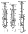
- the first embodiment illustrated in Figs. 1 to 3, is of the type wherein the plunger engages the ampoule itself.
- the plunger is designed to engage the needle support member.
- the dental injection device illustrated therein comprises a barrel section 4, closed at one end by a cap 5 and having a small aperture 6 at its other end through which the needle for injection is able to project.
- a plunger 7 Extending axially through the cap 5 into the interior of the barrel 4 is a plunger 7, which may be moved linearly by means of a handle 8 on its outer end.
- a fine-bore, double-ended needle 9 is carried by a needle support in the form of a short, generally cylindrical plug 10, which is free to slide axially within the barrel 4.
- the face of the plug 10 remote from the aperture 6 is shaped to form an inturned cylindrical extension 11, which is of such dimensions as to clip resiliently over the neck of a conventional ampoule 12 of anaesthetic, introduced into the barrel 4 by the dentist.
- the ampoule 12 is sealed by a plug 13, which is able to slide within the ampoule to eject liquid.
- the plunger 7 is constructed of two coaxial parts, which may conveniently be called an inner plunger 15 and outer plunger 16.
- the inner plunger 15 terminates in a flat disc-shaped head 17 which is able to enter the wider end of the ampoule 12 to push the plug 13.
- the outer plunger 16 terminates in an annular head 18 and a resilient O-ring 19 is located between the head 17 of the inner plunger 15 and the head 18 of the outer plunger.
- a resilient O-ring 19 is located between the head 17 of the inner plunger 15 and the head 18 of the outer plunger.
- a spring located in the handle 8 normally urges the plunger heads 17 and 18 towards each other and thereby squeezes the O-ring 19 into gripping engagement with the ampoule. Relative axial movement of the plungers 15 and 16 is limited by lateral pins 20 on the handle 8 extending into a pair of "windows" 21 in the outer plunger 16.
- the pull on the handle 8 necessary to withdraw the plunger assembly also causes the heads 17 and 18 to approach each other and cause the O-ring 19 to engage the inner face of the ampoule 12.
- the ampoule 12 and the needle support member 10 are retracted with the plunger until the needle lies wholly within the barrel 4.
- the end of the ampoule 12 abuts a cylindrical inward extension 24 of the cap 5.
- a circumferential projection 22 on the plug 10 locks into an indent 23 on the inner face of the barrel 4 and retains the plug 10 and ampoule 12 against further movement relative to the barrel.
- Further retraction of the plunger causes the O-ring 19 to slide against friction until it disengages itself from the ampoule 12, which is left in its locked position within the barrel 4.
- the barrel may now be separated from cap 5 (for example by a twisting "bayonet”action) and the barrel and its contents, namely the needle and ampoule, may be discarded safely without handling of these potentially dangerous contents.
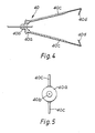
- the second embodiment of the injection device makes use of a different form of needle support device in the form of a "needle carriage" 40.
- the carriage 40 (Figs. 4 and 5) has a short cylindrical body part 40 a , a forwardly-projecting boss 40 b and, in the illustrated form, two rearwardly-extending arms 40 c , each terminating in an in-turned claw 40 d .
- Fig. 4 and 5 has a short cylindrical body part 40 a , a forwardly-projecting boss 40 b and, in the illustrated form, two rearwardly-extending arms 40 c , each terminating in an in-turned claw 40 d .
- the carriage 40 with a needle 41 extending axially through the body part 40 a and boss 40 b , is a snug sliding fit within a cylindrical barrel 42 and, when fully inserted in the barrel, allows the boss and needle to project through an aperture 43 in the otherwise closed end of the barrel.
- the projecting end of the needle is at this stage protected by a sheath 44.
- an ampoule 52 of anaesthetic When an ampoule 52 of anaesthetic is introduced into the open end of the barrel 42, it can readily deflect the resilient claws 40 d and be further inserted as far as the point where it encounters the inner end of the needle 41, on to which it is guided by inclined internal shoulders 40 e on the carriage 40.
- the ampoule is shown in Fig. 7 in its position of use. At this point, the claws 40 d have resumed their natural at-rest position.
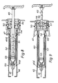
- a single plunger 45 is supported axially within the barrel 42 by means of a cap 46 which locks on to the open end of the barrel.
- the cap is held in place by means of claws 47, which engage an annular shoulder 48 on the barrel 42.
- the claws 47 are pivoted at 49 and are normally urged into the position shown in Figs. 7 and 8 by a circular spring 50.
- the plunger 45 has a series of indentations 51 along a part of its length and these can easily deflect the claws 40 d as the plunger advances. Thus forward movement of the plunger pushes a plug 53 in the ampoule 52 and expels anaesthetic through the needle 41 for injection in the manner of a conventional dental gun.
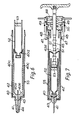
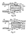
- the third embodiment of the injection device according to the invention resembles the second embodiment illustrated in Figs. 4 to 9 except in those details illustrated in Figs. 10 and 11.
- the device for interconnecting and subsequently disconnecting the plunger and the needle carriage takes a different form.
- the needle carrier 60 has two or more rearwardly-extending arms 60 a , each having an inturned lip 60 b . As illustrated, the arms 60 a extend beyond the end of an ampoule 61 located within the needle carrier such that the lips 60 b may be captured by the plunger.
- the plunger 62 has a forward extension 62 a of reduced diameter so as to form a shoulder 62 b and the extension 62 a carries a generally cylindrical cover 63, of such radial dimension as to be able to slide within the ampoule 61 and advance the conventional plug therein (not shown) in order to express anaesthetic from the ampoule in the usual manner.
- a bush 64 Slideably mounted upon the extension 62 a of the plunger 62 within the cover 63 is a bush 64 having resilient arms 64 a terminating in barbs 64 b .
- a helical compression spring 65 urges the bush 64 against the shoulder 62 b and, when the bush 64 is in its most rearward position, the barbs 64 b project radially outwardly through windows 63 a in the cover 63 and are thereby able to engage the lips 60 b .
- the barbs 64 b are readily deflected by the edge of the lips 60 b and by the edge of the ampoule 61, thus allowing the plunger to enter the ampoule and express anaesthetic through the syringe needle.
- the barbs 64 b spring radially outwardly to engage the lips 60 b , such that the needle carrier is withdrawn with the plunger until the needle lies wholly within the syringe barrel.
- the bush 64 On further withdrawal of the plunger, the bush 64 abuts an annular end-stop 66 projecting from the cap 67 of the syringe.
- the plunger 62 and cover 63 are able to continue to move axially by a short distance relative to the bush 64, against the resistance of spring 65, and this short relative movement of cover 63 and bush 64 causes the barbs 64 b to ride radially inwardly over the forward edges of the windows 63 a ; in this way, the barbs clear the lips 60 b and the plunger becomes disconnected from the needle carrier 60.
- claws on the cap 67 similar to the claws 47 of Figs. 7 to 9 are deflected to enable the cap to be separated from the syringe barrel. The barrel and its contents may now be discarded as before.
Abstract
Description
- The present invention is an injection device which has been devised to be of enhanced safety in use compared with many prior such devices. It is of particular value as applied to the application of dental injections but is potentially of merit for other injection purposes.
- Dentists generally nowadays apply local anaesthetic to the area of the gums using a gun type of anaesthetic injector. Injectors of this type comprise a steel cylinder and a hand-operated plunger working within the cylinder. Anaesthetic is introduced in the form of a glass ampoule into the cylinder and injection is via a fine-bore, double-ended needle. The operating procedure requires the dentist to fit the needle to the body of the gun before or after inserting the ampoule of anaesthetic into the cylinder and thereby to cause the ampoule to be penetrated by the inner end of the needle. After removal of a protective sheath from the outer end of the needle, the anaesthetic may be injected as required.
- While such devices have proved to be very useful, the removal and disposal of the needle after use is a potentially hazardous operation in that it entails the handling of a double-ended needle, of which at least the outer end (and often also the inner end) is contaminated by the patient's body fluids, for example blood or saliva, which may contain infectious agents. Thus there is a serious risk of the dentist accidentally piercing his own skin and thereby introducing an infection or other contaminant into his body. An attemp to re-sheath the outer end of the needle before removing it from the cylinder of the injection gun entails its own dangers and still leaves the inner end of the needle exposed. The removal of the needle and the ampoule from the cylinder before again using the injection gun, and the subsequent disposal of needle and ampoule, pose a serious potential hazard to the dentist, his staff and members of the general public.
- The present invention has been devised with the object of reducing or eliminating these hazards which characterise use of existing such devices, and in particular of eliminating the need to handle the double-ended needles after use.
- The injection device according to the present invention comprises a generally cylindrical barrel section, substantially closed at a first end thereof but having an aperture in said closed end to permit passage of an injection needle therethrough, a needle support member carrying an injection needle and of such dimensions as to fit within the barrel section for sliding movement axially therein between a forward position in which said needle extends through said aperture and a rearward position in which said needle lies wholly within said barrel section, said needle support member further being shaped to receive one end of a liquid container also within said barrel section, and a plunger, mounted at the second end of said barrel section for axial movement therein and adapted by forward said movement to express liquid from a said container and to interconnect with either the needle support member or a said liquid container such that subsequent rearward movement of said plunger withdraws the needle support member into its rearward position.
- In use of the injection device according to the invention, the needle support member, carrying a conventional double-ended needle, is located within the barrel section with one end of the needle projecting through the aperture at the first end of the barrel section. At presentation, the projecting end of the needle will be protected by an enclosing, disposable plastic sheath. A conventional liquid ampoule is introduced into the barrel section and when the plunger is depressed it presses the ampoule into contact with the support member, where the ampoule is pierced by the inner end of the needle. Further operation of the plunger expels liquid from the ampule through the needle for injection in the usual way. However, when the injection is completed, withdrawal of the plunger also achieves withdrawal of the ampoule and of the needle support member into the barrel section until the outer end of the needle is no longer exposed. The barrel section, ampoule and needle may then together be disconnected from the plunger and discarded with the needle fully protected, without any risk of accidental injury to the user.
- The generally cylindrical barrel section may be made of steel as is usual but, since the intention is that it should be discarded after a single use, it is preferred that it be made of a synthetic plastics material. The barrel section may be similar to that of a conventional dental injection gun but is preferably a little longer, to permit full retraction of the needle with the ampoule into the barrel.
- The needle support member may conveniently take the form of a short, generally cylindrical plug or bung, of slightly smaller radial diameter than the internal diameter of the barrel section and having the needle extending axially through it. The needle support is shaped to receive one end of a liquid container within the barrel section and may either merely be internally somewhat tapered so as to locate the container centrally within the barrel section and assist its alignment with the inner end of the needle, or may positively engage and grip the container. For example, the needle support member may incorporate connector means designed to be a snap fit over the outside of the neck of a conventional ampoule. Thus in one form the needle support member may be a unitary moulding in a resilient synthetic plastics material, having an inturned short cylindrical extension or collar to snap over the ampoule neck. In a preferred form described below, the needle support member is designed to permit the plunger to pass into the container in a forward direction and to remain interconnected to the needle support member when the plunger is being withdrawn.
- The plunger is mounted at the second end of the barrel section for axial movement within that section. The plunger may be mounted in a cap designed to fit over or within the open barrel end and having an axial aperture to support and guide the plunger. The cap and plunger may themselves be intended to be discarded with the barrel, ampoule and needle after a single use, in which case the cap may be hinged to the barrel as in a conventional dental injection gun, to permit insertion of the ampoule. However in the interest of keeping costs down to acceptable levels, it is strongly preferred for the cap and barrel to be mutually separable before and after use, so that the cap and plunger may be used several or many times before eventually being replaced. To that end, the cap may be a simple tight push-fit into or on to the end of the barrel, or the connection may be a screw connection of a spring-loaded, self-locking type, for example a bayonet-type connection.
- Ampoules of anaesthetic for dental injection guns are usually manufactured to a standard format, having a bung slidable within the ampoule and urged down the internal length of the ampoule by a plunger. To enable such conventional ampoules to be used with the improved gun of the present invention, the plunger may similarly be of such dimensions, at its free end, as to enter a conventional ampoule and push the bung. A second function to be performed by the plunger is to interconnect with either the needle support member or, if the latter is of the type which locks on to the liquid container, the container itself, so that withdrawal of the plunger also retracts the liquid container and the needle.
- In a preferred form of the invention, the interconnection is between the needle support member and the plunger. The means for achieving this interconnection may very conveniently take the form of one or more resilient elongated extensions of the needle support member, adapted to extend beyond the length of the liquid container and to engage in one or more projections extending laterally from the plunger. Preferably these extensions positively engage the projections only in the direction of withdrawal of the plunger. Advantageously, provision is made for disengagement of the projections after withdrawl of the plunger, to simplify subsequent disposal of the ampoule, needle support member and cylinder.
- In an alternative, less preferred form of the invention, the plunger is designed to be able to engage the ampoule itself. A very convenient way of achieving this is for the plunger to carry, at or adjacent to its end which enters the ampoule, a radially expandable plug. For example, the plug may be an O-ring of rubber or resilient synthetic plastics material, which by axial pressure may be caused to expand radially to engage the inner surface of the ampoule. The radial expansion of the plunger plug may be achieved by forming the plunger in two coaxial sections, which by relative axial movement are able to apply axial pressure on the plug as desired.
- As a preferred feature of the injection device according to the present invention, locking means may be provided to retain the ampoule and needle in the retracted position within the barrel section after use. A simple preferred mechanical form of the locking means is a radial projection from the needle support member and a corresponding detent in the inner face of the barrel section at a point corresponding to the retracted position of the needle support member. As an alternative, the needle support member and barrel section may be locked together chemically after use, by providing their abutting surfaces with suitable chemically interacting coatings.
- The invention will now be further described with reference to the accompanying drawings, wherein three specific embodiments of the invention are illustrated. The first embodiment, illustrated in Figs. 1 to 3, is of the type wherein the plunger engages the ampoule itself. In the second and third embodiments, which are illustrated in Figs. 4 to 11 and which represent particularly preferred forms of the invention, the plunger is designed to engage the needle support member.
- In the drawings:-
- Fig. 1 is a longitudinal sectional view of the first embodiment of the device, in a condition wherein it is ready for use;
- Fig. 2 is a view corresponding to Fig. 1, shortly after the device has been used to give an injection and with the needle and ampoule partly retracted;
- Fig. 3 is a view corresponding to Figs. 1 and 2, with the needle and ampoule fully retracted, shortly before they are discarded;
- Fig. 4 is a longitudinal sectional view of the needle support member which is a component of the second embodiment of the device;
- Fig. 5 is an elevation from the front of the support member of Fig. 4;
- Fig. 6 is a longitudinal sectional view of the cylindrical barrel section of the second embodiment, with the needle support member in place and the ampoule ready for insertion;
- Fig. 7 is a longitudinal sectional view of the complete dental injection device in its second embodiment, just before an injection is administered;
- Fig. 8 is a view corresponding to Fig. 7, with the ampoule and needle support member fully withdrawn;
- Fig. 9 is a view corresponding to Figs. 7 and 8, with the barrel, ampoule and needle support member disconnected from the plunger assembly before they are discarded;
- Fig. 10 is a longitudinal sectional view of a detail of a third embodiment of the invention, showing the means for interconnecting the plunger and the needle support member in the interconnecting condition; and
- Fig. 11 is a view corresponding to Fig. 10, showing the plunger and needle support member disconnected from each other.
- Referring firstly to Figs. 1 to 3, the dental injection device illustrated therein comprises a
barrel section 4, closed at one end by acap 5 and having a small aperture 6 at its other end through which the needle for injection is able to project. Extending axially through thecap 5 into the interior of thebarrel 4 is aplunger 7, which may be moved linearly by means of ahandle 8 on its outer end. - A fine-bore, double-ended needle 9 is carried by a needle support in the form of a short, generally
cylindrical plug 10, which is free to slide axially within thebarrel 4. The face of theplug 10 remote from the aperture 6 is shaped to form an inturnedcylindrical extension 11, which is of such dimensions as to clip resiliently over the neck of aconventional ampoule 12 of anaesthetic, introduced into thebarrel 4 by the dentist. Theampoule 12 is sealed by aplug 13, which is able to slide within the ampoule to eject liquid. When the ampoule is first introduced into thebarrel 4, the inner end of the needle 9 pierces acap 14 which covers the top of theampoule 12. - The
plunger 7 is constructed of two coaxial parts, which may conveniently be called aninner plunger 15 andouter plunger 16. Theinner plunger 15 terminates in a flat disc-shapedhead 17 which is able to enter the wider end of theampoule 12 to push theplug 13. Thus, beginning with the injection device in the position illustrated in Fig. 1, the plunger is first depressed slightly, following the normal practice, to ensure free flow of anaesthetic through the needle. After the needle 9 has been introduced into the patient's gum, movement of the plunger further into thebarrel 4 by means of thehandle 8, which is secured to theinner plunger 15, causes anaesthetic from theampoule 12 to be ejected via the needle 9. - The
outer plunger 16 terminates in anannular head 18 and a resilient O-ring 19 is located between thehead 17 of theinner plunger 15 and thehead 18 of the outer plunger. Thus relative axial movement of theplungers ring 19 so as to cause it to expand radially into contact with the inner face of theampoule 12 as shown in Fig. 2. - A spring located in the
handle 8 normally urges the plunger heads 17 and 18 towards each other and thereby squeezes the O-ring 19 into gripping engagement with the ampoule. Relative axial movement of theplungers lateral pins 20 on thehandle 8 extending into a pair of "windows" 21 in theouter plunger 16. When thehandle 8 is pressed in order to advance the plunger assembly into thebarrel 4, the pressure on the O-ring is released and the plunger can push theplug 13 into the ampoule. - When the injection is completed, the pull on the
handle 8 necessary to withdraw the plunger assembly also causes theheads ring 19 to engage the inner face of theampoule 12. Thus theampoule 12 and theneedle support member 10 are retracted with the plunger until the needle lies wholly within thebarrel 4. - At this stage, the end of the
ampoule 12 abuts a cylindricalinward extension 24 of thecap 5. Simultaneously acircumferential projection 22 on theplug 10 locks into anindent 23 on the inner face of thebarrel 4 and retains theplug 10 andampoule 12 against further movement relative to the barrel. Further retraction of the plunger causes the O-ring 19 to slide against friction until it disengages itself from theampoule 12, which is left in its locked position within thebarrel 4. - The barrel may now be separated from cap 5 (for example by a twisting "bayonet"action) and the barrel and its contents, namely the needle and ampoule, may be discarded safely without handling of these potentially dangerous contents.
- Turning now to Figs. 4 to 9 of the accompanying drawings, the second embodiment of the injection device according to the present invention makes use of a different form of needle support device in the form of a "needle carriage" 40. The carriage 40 (Figs. 4 and 5) has a short
cylindrical body part 40a, a forwardly-projectingboss 40b and, in the illustrated form, two rearwardly-extending arms 40c, each terminating in an in-turnedclaw 40d. As shown in Fig. 6, thecarriage 40, with aneedle 41 extending axially through thebody part 40a andboss 40b, is a snug sliding fit within acylindrical barrel 42 and, when fully inserted in the barrel, allows the boss and needle to project through anaperture 43 in the otherwise closed end of the barrel. The projecting end of the needle is at this stage protected by asheath 44. - When an
ampoule 52 of anaesthetic is introduced into the open end of thebarrel 42, it can readily deflect theresilient claws 40d and be further inserted as far as the point where it encounters the inner end of theneedle 41, on to which it is guided by inclinedinternal shoulders 40e on thecarriage 40. The ampoule is shown in Fig. 7 in its position of use. At this point, theclaws 40d have resumed their natural at-rest position. - A
single plunger 45 is supported axially within thebarrel 42 by means of acap 46 which locks on to the open end of the barrel. The cap is held in place by means ofclaws 47, which engage anannular shoulder 48 on thebarrel 42. Theclaws 47 are pivoted at 49 and are normally urged into the position shown in Figs. 7 and 8 by acircular spring 50. By virtue of theclaws 47, thecap 46 andbarrel 42 are locked together against inadvertent separation until, by a mechanism described below, the lock is released by complete retraction of the plunger, ampoule and needle. - The
plunger 45 has a series ofindentations 51 along a part of its length and these can easily deflect theclaws 40d as the plunger advances. Thus forward movement of the plunger pushes aplug 53 in theampoule 52 and expels anaesthetic through theneedle 41 for injection in the manner of a conventional dental gun. - When injection is complete, the
plunger 45 is withdrawn and theclaws 40d are now captured by theindentations 51, with the result that thecarriage 40 and theampoule 52 are withdrawn with the plunger, the needle being retracted into the barrel. When retraction is complete (Fig. 8), theclaws 40d are engaged and deflected by acylindrical projection 54 on thecap 46, enabling theindentations 51 to pass those claws so that further withdrawal of theplunger 45 leaves the needle carriage, needle and ampoule within the barrel. At this point, aperipheral projection 40f on the needle carriage locks into anindent 55 on the inner face of the barrel and secures the carriage and associated components within the barrel. - Further withdrawal of the
plunger 45 moves a spring-loadedpiston 56 within thecap 46 in such a direction (see Fig. 9) that aninclined face 57 of the piston deflects theclaws 47 against the pressure of thecircular spring 50 and disengages them from theannular shoulder 48. Thus the barrel and its contents may now be separated from the cap-and-plunger assembly and safely discarded. - It will be observed that those items which have been used in the injection procedure and thereby exposed to the risk of contamination have thus been separated and discarded without any handling by the user of the dental injection gun.
- The third embodiment of the injection device according to the invention, which will now be described, resembles the second embodiment illustrated in Figs. 4 to 9 except in those details illustrated in Figs. 10 and 11. As illustrated, in this third embodiment, the device for interconnecting and subsequently disconnecting the plunger and the needle carriage takes a different form.
- Referring to Figs. 10 and 11, the
needle carrier 60 has two or more rearwardly-extendingarms 60a, each having aninturned lip 60b. As illustrated, thearms 60a extend beyond the end of anampoule 61 located within the needle carrier such that thelips 60b may be captured by the plunger. Theplunger 62 has aforward extension 62a of reduced diameter so as to form ashoulder 62b and theextension 62a carries a generallycylindrical cover 63, of such radial dimension as to be able to slide within theampoule 61 and advance the conventional plug therein (not shown) in order to express anaesthetic from the ampoule in the usual manner. - Slideably mounted upon the
extension 62a of theplunger 62 within thecover 63 is abush 64 having resilient arms 64a terminating inbarbs 64b. Ahelical compression spring 65 urges thebush 64 against theshoulder 62b and, when thebush 64 is in its most rearward position, thebarbs 64b project radially outwardly throughwindows 63a in thecover 63 and are thereby able to engage thelips 60b. - When the
plunger 62 is first advanced within the syringe barrel (not shown), thebarbs 64b are readily deflected by the edge of thelips 60b and by the edge of theampoule 61, thus allowing the plunger to enter the ampoule and express anaesthetic through the syringe needle. However, when injection is completed and the plunger is subsequently withdrawn from the ampoule, thebarbs 64b spring radially outwardly to engage thelips 60b, such that the needle carrier is withdrawn with the plunger until the needle lies wholly within the syringe barrel. - On further withdrawal of the plunger, the
bush 64 abuts an annular end-stop 66 projecting from the cap 67 of the syringe. Theplunger 62 and cover 63 are able to continue to move axially by a short distance relative to thebush 64, against the resistance ofspring 65, and this short relative movement ofcover 63 andbush 64 causes thebarbs 64b to ride radially inwardly over the forward edges of thewindows 63a; in this way, the barbs clear thelips 60b and the plunger becomes disconnected from theneedle carrier 60. Simultaneously, claws on the cap 67 similar to theclaws 47 of Figs. 7 to 9 are deflected to enable the cap to be separated from the syringe barrel. The barrel and its contents may now be discarded as before.
Claims (11)
Applications Claiming Priority (2)
| Application Number | Priority Date | Filing Date | Title |
|---|---|---|---|
| GB8630016 | 1986-12-16 | ||
| GB868630016A GB8630016D0 (en) | 1986-12-16 | 1986-12-16 | Dental injection device |
Publications (3)
| Publication Number | Publication Date |
|---|---|
| EP0272035A2 true EP0272035A2 (en) | 1988-06-22 |
| EP0272035A3 EP0272035A3 (en) | 1989-03-15 |
| EP0272035B1 EP0272035B1 (en) | 1991-08-21 |
Family
ID=10609078
Family Applications (1)
| Application Number | Title | Priority Date | Filing Date |
|---|---|---|---|
| EP87310770A Expired - Lifetime EP0272035B1 (en) | 1986-12-16 | 1987-12-08 | Injection device |
Country Status (8)
| Country | Link |
|---|---|
| US (1) | US4957490A (en) |
| EP (1) | EP0272035B1 (en) |
| JP (1) | JPS63192453A (en) |
| AU (1) | AU595408B2 (en) |
| DE (1) | DE3772349D1 (en) |
| ES (1) | ES2023661B3 (en) |
| GB (2) | GB8630016D0 (en) |
| IN (1) | IN172213B (en) |
Cited By (20)
| Publication number | Priority date | Publication date | Assignee | Title |
|---|---|---|---|---|
| EP0325049A2 (en) * | 1988-01-15 | 1989-07-26 | Btg International Limited | Single-use syringe |
| WO1989012476A1 (en) * | 1988-06-22 | 1989-12-28 | Claude Favard | Single-use, self-blocking hypodermic syringe |
| FR2634650A1 (en) * | 1988-08-01 | 1990-02-02 | Labouze Joseph | NON REUSABLE SYRINGE |
| WO1990001962A1 (en) * | 1988-08-26 | 1990-03-08 | Haak Abraham V D | Safety device for an injection syringe needle |
| EP0388169A2 (en) * | 1989-03-14 | 1990-09-19 | Eastman Kodak Company | Needle device for safely collecting blood or injecting drugs |
| WO1991012842A1 (en) * | 1990-03-01 | 1991-09-05 | Advanced Protective Injection Systems B.V. | Protection assembly for an injection syringe |
| EP0451314A1 (en) * | 1988-11-14 | 1991-10-16 | Habley Medical Technology Corporation | Dental syringe having a medication filled carpule and a retractable needle cannula |
| GB2262138A (en) * | 1991-12-03 | 1993-06-09 | Glaxo Group Ltd | Single dose dispenser. |
| FR2686242A1 (en) * | 1992-01-22 | 1993-07-23 | Barbier Georges | BLOOD SAMPLING DEVICE FOR AIR VACUUM TUBE. |
| EP0557559A1 (en) * | 1989-12-11 | 1993-09-01 | Habley Medical Technology Corporation | Ampule syringe with needle retraction |
| WO1993023098A1 (en) * | 1992-05-15 | 1993-11-25 | Safe-T-Limited | Syringe with retractable needle |
| FR2720001A1 (en) * | 1994-05-20 | 1995-11-24 | Sylvain Thuaudet | Medical injection syringe |
| EP0874649A1 (en) * | 1995-12-22 | 1998-11-04 | Science Incorporated | Fluid dispenser with fill adapter |
| EP0909190A1 (en) * | 1994-02-14 | 1999-04-21 | Univec, Inc. | Single-use syringe with aspirating mechanism |
| GB2404338A (en) * | 2003-07-30 | 2005-02-02 | Safe T Ltd | Actuator and containment device for a syringe |
| WO2012049480A1 (en) * | 2010-10-13 | 2012-04-19 | Sphere Medical Limited | Component with seal, receiving body, system and method |
| EP2559449A1 (en) * | 2011-07-06 | 2013-02-20 | King Saud University | Safety syringe |
| EP2829296A1 (en) * | 2013-07-24 | 2015-01-28 | Raumedic Ag | Medical injection device |
| EP2686046A4 (en) * | 2011-03-17 | 2015-09-02 | Becton Dickinson Co | Medical injector with rotatable ratcheting plunger |
| US9522239B2 (en) | 2008-09-18 | 2016-12-20 | Becton, Dickinson And Company | Medical injector with ratcheting plunger |
Families Citing this family (47)
| Publication number | Priority date | Publication date | Assignee | Title |
|---|---|---|---|---|
| US5624400A (en) * | 1990-05-09 | 1997-04-29 | Safety Syringes, Inc. | Disposable self-shielding aspirating syringe |
| US5437647A (en) * | 1990-05-09 | 1995-08-01 | Safety Syringes, Inc. | Disposable self-shielding aspirating syringe |
| AT398694B (en) * | 1990-07-19 | 1995-01-25 | Avl Verbrennungskraft Messtech | DEVICE FOR DETERMINING THE CONCENTRATION OF AT LEAST ONE SUBSTANCE IN ORGANIC TISSUE |
| ATE129906T1 (en) * | 1990-07-19 | 1995-11-15 | Nardino Righi | SINGLE USE SAFETY SYRINGE. |
| US5114404A (en) * | 1990-07-24 | 1992-05-19 | Paxton Gerald R | Multifunctional retractable needle type general purpose disabling syringe having enhanced safety features and related method of operation |
| US5098390A (en) * | 1990-09-07 | 1992-03-24 | Retractable I, Inc. | Hand syringe with safety storage for used needle |
| US5125908A (en) * | 1990-10-19 | 1992-06-30 | Cohen Milton J | Hypodermic syringe with protective holder |
| US5201719A (en) * | 1991-05-06 | 1993-04-13 | Collins Cary C | Disposable hypodermic needle and medication catridge |
| US5176656A (en) * | 1991-08-12 | 1993-01-05 | Bayless William B | Automatically positioned needle sheath for a disposable hypodermic syringe |
| US5318547A (en) * | 1992-01-15 | 1994-06-07 | Altschuler Bruce R | Sheathed hypodermic needle |
| AU651662B2 (en) * | 1992-03-02 | 1994-07-28 | Habley Medical Technology Corporation | Safety module activator reshielding tool |
| US5269766A (en) * | 1992-06-09 | 1993-12-14 | Habley Medical Technology Corporation | Dental syringe having an automatically retractable medication carpule and needle cannula |
| US5352208A (en) * | 1992-11-30 | 1994-10-04 | Robinson Wilbur D | Safe non-reusable hypodermic syringe |
| US5380295A (en) * | 1992-12-14 | 1995-01-10 | Mallinckrodt Medical, Inc. | Delivery apparatus with mechanism preventing rearward movement of a piston disposed therein |
| US5514107A (en) * | 1994-02-10 | 1996-05-07 | Habley Medical Technology Corporation | Safety syringe adapter for cartridge-needle unit |
| US5746215A (en) * | 1996-11-01 | 1998-05-05 | U.S. Medical Instruments, Inc. | IV infusion or collection device with extendable and retractable needle |
| US6319234B1 (en) * | 1997-02-12 | 2001-11-20 | Sergio Restelli | Disposable safety syringe |
| US6530903B2 (en) | 2000-02-24 | 2003-03-11 | Xiping Wang | Safety syringe |
| US6676641B2 (en) * | 2001-09-05 | 2004-01-13 | Futura Medical Technologies, Inc. | Retractable hypodermic syringe |
| JP4141156B2 (en) * | 2002-03-15 | 2008-08-27 | 日本ベクトン・ディッキンソン株式会社 | Prefilled syringe with plunger retraction limit mechanism |
| US7393343B2 (en) * | 2002-07-02 | 2008-07-01 | Hypoguard Usa Inc. | Retractable hypodermic syringe |
| US6599270B1 (en) * | 2002-10-29 | 2003-07-29 | Cho Ying Chen | Syringe with a snapping device for backward pulling the needle into the syringe after syringing |
| US20090204076A1 (en) * | 2003-02-03 | 2009-08-13 | Barry Peter Liversidge | Medical Injector |
| FR2855413B1 (en) * | 2003-05-26 | 2005-12-30 | Becton Dickinson France | PRE-FILLED SYRINGE WITH ANTI-EFFRACTION COIFFE |
| CA2584106C (en) | 2004-10-14 | 2011-09-06 | Safety Medical International, Incorporated | Safety medical syringe with retractable needle |
| US8372044B2 (en) | 2005-05-20 | 2013-02-12 | Safety Syringes, Inc. | Syringe with needle guard injection device |
| US7846135B2 (en) | 2006-02-24 | 2010-12-07 | Midland Medical Holding LLC | Retractable needle syringe with needle trap |
| CN100418593C (en) * | 2006-10-09 | 2008-09-17 | 李文勇 | Disposable self-destructing safety anesthesia syringe |
| CA2682699A1 (en) * | 2007-03-21 | 2008-09-25 | Midland Medical Devices Holdings, Llc | Safety medical syringe with retractable needle and including a plunger that is received within a barrel |
| US20090093793A1 (en) | 2007-10-02 | 2009-04-09 | Yossi Gross | External drug pump |
| MX2011009168A (en) | 2009-03-13 | 2011-09-15 | Lilly Co Eli | Apparatus for injecting a pharmaceutical with automatic syringe retraction following injection. |
| CA2774586A1 (en) * | 2009-09-30 | 2011-04-07 | Sanofi-Aventis Deutschland Gmbh | Method and assembly for a drug delivery device |
| US9623193B2 (en) * | 2011-12-06 | 2017-04-18 | Robert J. Cohn | Syringe assembly with automatic safety shield |
| KR101296559B1 (en) | 2011-12-19 | 2013-08-13 | 조희민 | Cylinder for syringe |
| ITRM20120514A1 (en) * | 2012-10-26 | 2014-04-27 | Mauro Pepe | DISPOSABLE SYRINGE WITH RETRACTABLE NEEDLE. |
| EP2902061A1 (en) * | 2014-01-30 | 2015-08-05 | Sanofi-Aventis Deutschland GmbH | Medicament delivery device |
| EP2944340A1 (en) * | 2014-05-12 | 2015-11-18 | Sanofi | Activating mechanism for a medicament delivery device and medicament delivery device |
| EP2944341A1 (en) * | 2014-05-12 | 2015-11-18 | Sanofi | Activating mechanism for a medicament delivery device and medicament delivery device |
| US10576207B2 (en) | 2015-10-09 | 2020-03-03 | West Pharma. Services IL, Ltd. | Angled syringe patch injector |
| CN108472438B (en) | 2015-10-09 | 2022-01-28 | 西医药服务以色列分公司 | Tortuous fluid path attachment to pre-filled fluid reservoirs |
| WO2017076925A1 (en) | 2015-11-05 | 2017-05-11 | Sanofi-Aventis Deutschland Gmbh | Cartridge carrier assembly |
| CN111544704B (en) * | 2016-01-21 | 2022-06-03 | 西医药服务以色列有限公司 | Force containment in autoinjectors |
| JP6542481B2 (en) | 2016-01-21 | 2019-07-10 | ウェスト ファーマ サービシーズ イスラエル リミテッド | system |
| JP6885960B2 (en) | 2016-01-21 | 2021-06-16 | ウェスト ファーマ サービシーズ イスラエル リミテッド | Drug delivery device with visual indicators |
| US11389597B2 (en) | 2016-03-16 | 2022-07-19 | West Pharma. Services IL, Ltd. | Staged telescopic screw assembly having different visual indicators |
| JP6869327B2 (en) | 2016-08-01 | 2021-05-12 | ウェスト ファーマ サービシーズ イスラエル リミテッド | Anti-rotation cartridge |
| JP6921997B2 (en) | 2017-05-30 | 2021-08-18 | ウェスト ファーマ サービシーズ イスラエル リミテッド | Modular drive train for wearable syringes |
Citations (3)
| Publication number | Priority date | Publication date | Assignee | Title |
|---|---|---|---|---|
| FR2138157A1 (en) * | 1971-05-19 | 1972-12-29 | Etimex Gmbh | Throw-away plastic hypodermic - for use with standard cylindrical ampoules |
| US3884230A (en) * | 1973-09-27 | 1975-05-20 | Goldwyn L Wulff | Flexible needle and guard device for a hypodermic syringe |
| US3890971A (en) * | 1973-10-23 | 1975-06-24 | Thomas A Leeson | Safety syringe |
Family Cites Families (4)
| Publication number | Priority date | Publication date | Assignee | Title |
|---|---|---|---|---|
| US4148316A (en) * | 1977-08-29 | 1979-04-10 | Stewart-Naumann Laboratories, Inc. | Self-sealed hypodermic syringe |
| US4664653A (en) * | 1986-02-24 | 1987-05-12 | Sagstetter William E | Manually operated reusable injection apparatus |
| US4767413A (en) * | 1987-04-20 | 1988-08-30 | Habley Medical Technology Corporation | Dental syringe having an automatically retractable needle |
| US4834717A (en) * | 1987-09-25 | 1989-05-30 | Habley Medical Technology Corporation | Disposable, pre-sterilizable syringe for a pre-filled medication cartridge |
-
1986
- 1986-12-16 GB GB868630016A patent/GB8630016D0/en active Pending
-
1987
- 1987-12-08 IN IN1047/DEL/87A patent/IN172213B/en unknown
- 1987-12-08 EP EP87310770A patent/EP0272035B1/en not_active Expired - Lifetime
- 1987-12-08 ES ES87310770T patent/ES2023661B3/en not_active Expired - Lifetime
- 1987-12-08 GB GB8728683A patent/GB2200283B/en not_active Expired - Fee Related
- 1987-12-08 DE DE8787310770T patent/DE3772349D1/en not_active Expired - Lifetime
- 1987-12-10 US US07/131,228 patent/US4957490A/en not_active Expired - Fee Related
- 1987-12-15 AU AU82538/87A patent/AU595408B2/en not_active Ceased
- 1987-12-16 JP JP62316372A patent/JPS63192453A/en active Pending
Patent Citations (3)
| Publication number | Priority date | Publication date | Assignee | Title |
|---|---|---|---|---|
| FR2138157A1 (en) * | 1971-05-19 | 1972-12-29 | Etimex Gmbh | Throw-away plastic hypodermic - for use with standard cylindrical ampoules |
| US3884230A (en) * | 1973-09-27 | 1975-05-20 | Goldwyn L Wulff | Flexible needle and guard device for a hypodermic syringe |
| US3890971A (en) * | 1973-10-23 | 1975-06-24 | Thomas A Leeson | Safety syringe |
Cited By (46)
| Publication number | Priority date | Publication date | Assignee | Title |
|---|---|---|---|---|
| EP0325049A3 (en) * | 1988-01-15 | 1990-07-11 | National Research Development Corporation | Single-use syringe |
| GB2213383A (en) * | 1988-01-15 | 1989-08-16 | Nat Res Dev | Single-use syringe. |
| EP0325049A2 (en) * | 1988-01-15 | 1989-07-26 | Btg International Limited | Single-use syringe |
| AU617742B2 (en) * | 1988-01-15 | 1991-12-05 | British Technology Group Limited | Single-use syringe |
| GB2213383B (en) * | 1988-01-15 | 1991-10-30 | Nat Res Dev | Single-use syringe |
| WO1989012476A1 (en) * | 1988-06-22 | 1989-12-28 | Claude Favard | Single-use, self-blocking hypodermic syringe |
| EP0354824A2 (en) * | 1988-08-01 | 1990-02-14 | Joseph Labouze | Non rensable syringe |
| EP0354824A3 (en) * | 1988-08-01 | 1990-06-13 | Joseph Labouze | Non rensable syringe |
| US4978339A (en) * | 1988-08-01 | 1990-12-18 | Joseph Labouze | Non-reusable syringe |
| FR2634650A1 (en) * | 1988-08-01 | 1990-02-02 | Labouze Joseph | NON REUSABLE SYRINGE |
| US5380286A (en) * | 1988-08-23 | 1995-01-10 | Advanced Protective Injection Systems B.V. | Safety device for an injection syringe needle |
| EP0360313A1 (en) * | 1988-08-26 | 1990-03-28 | Advanced Protective Injection Systems B.V. | Safety device for an injection syringe needle |
| WO1990001962A1 (en) * | 1988-08-26 | 1990-03-08 | Haak Abraham V D | Safety device for an injection syringe needle |
| EP0451314A1 (en) * | 1988-11-14 | 1991-10-16 | Habley Medical Technology Corporation | Dental syringe having a medication filled carpule and a retractable needle cannula |
| EP0388169A2 (en) * | 1989-03-14 | 1990-09-19 | Eastman Kodak Company | Needle device for safely collecting blood or injecting drugs |
| EP0388169A3 (en) * | 1989-03-14 | 1991-07-31 | Eastman Kodak Company | Needle device for safely collecting blood or injecting drugs |
| EP0557559A1 (en) * | 1989-12-11 | 1993-09-01 | Habley Medical Technology Corporation | Ampule syringe with needle retraction |
| US5364359A (en) * | 1990-03-01 | 1994-11-15 | Advanced Protective Injection Systems Medical B.V. | Syringe with retractable needle |
| WO1991012842A1 (en) * | 1990-03-01 | 1991-09-05 | Advanced Protective Injection Systems B.V. | Protection assembly for an injection syringe |
| GB2262138B (en) * | 1991-12-03 | 1995-04-19 | Glaxo Group Ltd | Single dose dispenser |
| US5307953A (en) * | 1991-12-03 | 1994-05-03 | Glaxo Group Limited | Single dose dispenser having a piercing member |
| GB2262138A (en) * | 1991-12-03 | 1993-06-09 | Glaxo Group Ltd | Single dose dispenser. |
| AU663535B2 (en) * | 1991-12-03 | 1995-10-12 | Glaxo Group Limited | Single dose dispenser |
| FR2686242A1 (en) * | 1992-01-22 | 1993-07-23 | Barbier Georges | BLOOD SAMPLING DEVICE FOR AIR VACUUM TUBE. |
| EP0553024A1 (en) * | 1992-01-22 | 1993-07-28 | Georges Albert Eugène Barbier | Blood sampling device for a vacuum evacuated sample-tube |
| WO1993023098A1 (en) * | 1992-05-15 | 1993-11-25 | Safe-T-Limited | Syringe with retractable needle |
| EP0909190A1 (en) * | 1994-02-14 | 1999-04-21 | Univec, Inc. | Single-use syringe with aspirating mechanism |
| EP0909190A4 (en) * | 1994-02-14 | 2001-06-06 | Univec Inc | Single-use syringe with aspirating mechanism |
| FR2720001A1 (en) * | 1994-05-20 | 1995-11-24 | Sylvain Thuaudet | Medical injection syringe |
| EP0874649A1 (en) * | 1995-12-22 | 1998-11-04 | Science Incorporated | Fluid dispenser with fill adapter |
| EP0874649A4 (en) * | 1995-12-22 | 2000-02-09 | Science Inc | Fluid dispenser with fill adapter |
| GB2404338B (en) * | 2003-07-30 | 2007-01-24 | Safe T Ltd | Actuator and containment device for a syringe |
| US7670313B2 (en) | 2003-07-30 | 2010-03-02 | Safe-T Limited | Actuator and containment device for a syringe |
| GB2404338A (en) * | 2003-07-30 | 2005-02-02 | Safe T Ltd | Actuator and containment device for a syringe |
| US9707353B2 (en) | 2008-09-18 | 2017-07-18 | Becton, Dickinson And Company | Medical injector with ratcheting plunger |
| US10549047B2 (en) | 2008-09-18 | 2020-02-04 | Becton, Dickinson And Company | Medical injector with ratcheting plunger |
| US10143807B2 (en) | 2008-09-18 | 2018-12-04 | Becton, Dickinson And Company | Medical injector with ratcheting plunger |
| US10124120B2 (en) | 2008-09-18 | 2018-11-13 | Becton, Dickinson And Company | Medical injector with ratcheting plunger |
| US9522239B2 (en) | 2008-09-18 | 2016-12-20 | Becton, Dickinson And Company | Medical injector with ratcheting plunger |
| WO2012049480A1 (en) * | 2010-10-13 | 2012-04-19 | Sphere Medical Limited | Component with seal, receiving body, system and method |
| EP3251714A1 (en) * | 2011-03-17 | 2017-12-06 | Becton, Dickinson and Company | Medical injector with rotatable ratcheting plunger |
| EP3050587A1 (en) * | 2011-03-17 | 2016-08-03 | Becton Dickinson and Company | Medical injector with rotatable ratcheting plunger |
| EP2686046A4 (en) * | 2011-03-17 | 2015-09-02 | Becton Dickinson Co | Medical injector with rotatable ratcheting plunger |
| EP2559449A1 (en) * | 2011-07-06 | 2013-02-20 | King Saud University | Safety syringe |
| EP2829296A1 (en) * | 2013-07-24 | 2015-01-28 | Raumedic Ag | Medical injection device |
| US10493214B2 (en) | 2013-07-24 | 2019-12-03 | Raumedic Ag | Medical injection device |
Also Published As
| Publication number | Publication date |
|---|---|
| AU8253887A (en) | 1988-06-16 |
| GB2200283A (en) | 1988-08-03 |
| EP0272035B1 (en) | 1991-08-21 |
| IN172213B (en) | 1993-05-08 |
| ES2023661B3 (en) | 1992-02-01 |
| EP0272035A3 (en) | 1989-03-15 |
| DE3772349D1 (en) | 1991-09-26 |
| GB8728683D0 (en) | 1988-01-13 |
| GB8630016D0 (en) | 1987-01-28 |
| US4957490A (en) | 1990-09-18 |
| JPS63192453A (en) | 1988-08-09 |
| GB2200283B (en) | 1990-11-07 |
| AU595408B2 (en) | 1990-03-29 |
Similar Documents
| Publication | Publication Date | Title |
|---|---|---|
| EP0272035B1 (en) | Injection device | |
| US5573513A (en) | Prefilled cartridge syringe with needle system | |
| US6569115B1 (en) | Pre-filled retractable needle injection device | |
| US6752798B2 (en) | Retractable needle medical device for injecting fluid from a pre-filled cartridge | |
| US5637101A (en) | Quick release needle coupling system | |
| US5928205A (en) | Medical injection devices | |
| US7033343B2 (en) | Retractable needle medical device for injecting fluid from a pre-filled cartridge | |
| US6179812B1 (en) | Retractable needle medical devices | |
| EP0645154B1 (en) | Cartridge-needle unit having retractable needle | |
| US4904242A (en) | Phlebotomy set with safety retracting needle | |
| US4592744A (en) | Self-resheathing needle assembly | |
| EP0327061A1 (en) | Disposable retractable syringe | |
| US4878899A (en) | Disposable syringe for one-time use | |
| AU2003204787B2 (en) | Pre-filled retractable needle injection device | |
| EP1386628A2 (en) | Pre-filled retractable needle injection device | |
| AU2001284669A2 (en) | Retractable needle medical device for injecting fluid from pre-filled cartridge | |
| AU2002309503A1 (en) | Retractable needle medical device for injecting fluid from a pre-filled cartridge |
Legal Events
| Date | Code | Title | Description |
|---|---|---|---|
| PUAI | Public reference made under article 153(3) epc to a published international application that has entered the european phase |
Free format text: ORIGINAL CODE: 0009012 |
|
| AK | Designated contracting states |
Kind code of ref document: A2 Designated state(s): DE ES FR GB IT NL SE |
|
| 17P | Request for examination filed |
Effective date: 19881121 |
|
| PUAL | Search report despatched |
Free format text: ORIGINAL CODE: 0009013 |
|
| RHK1 | Main classification (correction) |
Ipc: A61M 5/24 |
|
| AK | Designated contracting states |
Kind code of ref document: A3 Designated state(s): DE ES FR GB IT NL SE |
|
| 17Q | First examination report despatched |
Effective date: 19900809 |
|
| GRAA | (expected) grant |
Free format text: ORIGINAL CODE: 0009210 |
|
| STAA | Information on the status of an ep patent application or granted ep patent |
Free format text: STATUS: THE PATENT HAS BEEN GRANTED |
|
| AK | Designated contracting states |
Kind code of ref document: B1 Designated state(s): DE ES FR IT NL SE |
|
| ET | Fr: translation filed | ||
| ITF | It: translation for a ep patent filed |
Owner name: JACOBACCI & PERANI S.P.A. |
|
| REF | Corresponds to: |
Ref document number: 3772349 Country of ref document: DE Date of ref document: 19910926 |
|
| PGFP | Annual fee paid to national office [announced via postgrant information from national office to epo] |
Ref country code: SE Payment date: 19911111 Year of fee payment: 5 |
|
| PGFP | Annual fee paid to national office [announced via postgrant information from national office to epo] |
Ref country code: NL Payment date: 19911231 Year of fee payment: 5 |
|
| PLBE | No opposition filed within time limit |
Free format text: ORIGINAL CODE: 0009261 |
|
| ITPR | It: changes in ownership of a european patent |
Owner name: CESSIONE;BRITISH TECHNOLOGY GROUP LIMITED |
|
| 26N | No opposition filed | ||
| REG | Reference to a national code |
Ref country code: FR Ref legal event code: TP |
|
| PG25 | Lapsed in a contracting state [announced via postgrant information from national office to epo] |
Ref country code: SE Effective date: 19921209 |
|
| NLS | Nl: assignments of ep-patents |
Owner name: BRITISH TECHNOLOGY GROUP LTD TE LONDEN, GROOT-BRIT |
|
| PG25 | Lapsed in a contracting state [announced via postgrant information from national office to epo] |
Ref country code: NL Effective date: 19930701 |
|
| REG | Reference to a national code |
Ref country code: ES Ref legal event code: PC2A Owner name: BRITISH TECHNOLOGY GROUP LIMITED |
|
| NLV4 | Nl: lapsed or anulled due to non-payment of the annual fee | ||
| PGFP | Annual fee paid to national office [announced via postgrant information from national office to epo] |
Ref country code: ES Payment date: 19941123 Year of fee payment: 8 |
|
| PGFP | Annual fee paid to national office [announced via postgrant information from national office to epo] |
Ref country code: FR Payment date: 19941129 Year of fee payment: 8 |
|
| EUG | Se: european patent has lapsed |
Ref document number: 87310770.0 Effective date: 19930709 |
|
| PGFP | Annual fee paid to national office [announced via postgrant information from national office to epo] |
Ref country code: DE Payment date: 19950224 Year of fee payment: 8 |
|
| PG25 | Lapsed in a contracting state [announced via postgrant information from national office to epo] |
Ref country code: ES Free format text: LAPSE BECAUSE OF EXPIRATION OF PROTECTION Effective date: 19951209 |
|
| PG25 | Lapsed in a contracting state [announced via postgrant information from national office to epo] |
Ref country code: FR Effective date: 19960830 |
|
| PG25 | Lapsed in a contracting state [announced via postgrant information from national office to epo] |
Ref country code: DE Effective date: 19960903 |
|
| REG | Reference to a national code |
Ref country code: FR Ref legal event code: ST |
|
| REG | Reference to a national code |
Ref country code: ES Ref legal event code: FD2A Effective date: 20010301 |
|
| PG25 | Lapsed in a contracting state [announced via postgrant information from national office to epo] |
Ref country code: IT Free format text: LAPSE BECAUSE OF NON-PAYMENT OF DUE FEES;WARNING: LAPSES OF ITALIAN PATENTS WITH EFFECTIVE DATE BEFORE 2007 MAY HAVE OCCURRED AT ANY TIME BEFORE 2007. THE CORRECT EFFECTIVE DATE MAY BE DIFFERENT FROM THE ONE RECORDED. Effective date: 20051208 |