EP3050527A1 - Treatment tool and treatment system - Google Patents
Treatment tool and treatment system Download PDFInfo
- Publication number
- EP3050527A1 EP3050527A1 EP14847518.9A EP14847518A EP3050527A1 EP 3050527 A1 EP3050527 A1 EP 3050527A1 EP 14847518 A EP14847518 A EP 14847518A EP 3050527 A1 EP3050527 A1 EP 3050527A1
- Authority
- EP
- European Patent Office
- Prior art keywords
- probe
- peripheral surface
- sheath
- actuator
- ultrasonic transducer
- Prior art date
- Legal status (The legal status is an assumption and is not a legal conclusion. Google has not performed a legal analysis and makes no representation as to the accuracy of the status listed.)
- Withdrawn
Links
Images







Classifications
-
- A—HUMAN NECESSITIES
- A61—MEDICAL OR VETERINARY SCIENCE; HYGIENE
- A61B—DIAGNOSIS; SURGERY; IDENTIFICATION
- A61B17/00—Surgical instruments, devices or methods
- A61B17/02—Surgical instruments, devices or methods for holding wounds open, e.g. retractors; Tractors
- A61B17/025—Joint distractors
-
- A—HUMAN NECESSITIES
- A61—MEDICAL OR VETERINARY SCIENCE; HYGIENE
- A61B—DIAGNOSIS; SURGERY; IDENTIFICATION
- A61B17/00—Surgical instruments, devices or methods
- A61B17/32—Surgical cutting instruments
- A61B17/320068—Surgical cutting instruments using mechanical vibrations, e.g. ultrasonic
-
- A—HUMAN NECESSITIES
- A61—MEDICAL OR VETERINARY SCIENCE; HYGIENE
- A61B—DIAGNOSIS; SURGERY; IDENTIFICATION
- A61B1/00—Instruments for performing medical examinations of the interior of cavities or tubes of the body by visual or photographical inspection, e.g. endoscopes; Illuminating arrangements therefor
- A61B1/32—Devices for opening or enlarging the visual field, e.g. of a tube of the body
-
- A—HUMAN NECESSITIES
- A61—MEDICAL OR VETERINARY SCIENCE; HYGIENE
- A61B—DIAGNOSIS; SURGERY; IDENTIFICATION
- A61B17/00—Surgical instruments, devices or methods
- A61B17/16—Instruments for performing osteoclasis; Drills or chisels for bones; Trepans
-
- A—HUMAN NECESSITIES
- A61—MEDICAL OR VETERINARY SCIENCE; HYGIENE
- A61B—DIAGNOSIS; SURGERY; IDENTIFICATION
- A61B17/00—Surgical instruments, devices or methods
- A61B17/16—Instruments for performing osteoclasis; Drills or chisels for bones; Trepans
- A61B17/1604—Chisels; Rongeurs; Punches; Stamps
-
- A—HUMAN NECESSITIES
- A61—MEDICAL OR VETERINARY SCIENCE; HYGIENE
- A61B—DIAGNOSIS; SURGERY; IDENTIFICATION
- A61B17/00—Surgical instruments, devices or methods
- A61B17/16—Instruments for performing osteoclasis; Drills or chisels for bones; Trepans
- A61B17/1613—Component parts
-
- A—HUMAN NECESSITIES
- A61—MEDICAL OR VETERINARY SCIENCE; HYGIENE
- A61B—DIAGNOSIS; SURGERY; IDENTIFICATION
- A61B17/00—Surgical instruments, devices or methods
- A61B17/16—Instruments for performing osteoclasis; Drills or chisels for bones; Trepans
- A61B17/1613—Component parts
- A61B17/1628—Motors; Power supplies
-
- A—HUMAN NECESSITIES
- A61—MEDICAL OR VETERINARY SCIENCE; HYGIENE
- A61B—DIAGNOSIS; SURGERY; IDENTIFICATION
- A61B17/00—Surgical instruments, devices or methods
- A61B17/16—Instruments for performing osteoclasis; Drills or chisels for bones; Trepans
- A61B17/1613—Component parts
- A61B17/1633—Sleeves, i.e. non-rotating parts surrounding the bit shaft, e.g. the sleeve forming a single unit with the bit shaft
-
- A—HUMAN NECESSITIES
- A61—MEDICAL OR VETERINARY SCIENCE; HYGIENE
- A61B—DIAGNOSIS; SURGERY; IDENTIFICATION
- A61B17/00—Surgical instruments, devices or methods
- A61B17/16—Instruments for performing osteoclasis; Drills or chisels for bones; Trepans
- A61B17/1657—Bone breaking devices
-
- A—HUMAN NECESSITIES
- A61—MEDICAL OR VETERINARY SCIENCE; HYGIENE
- A61B—DIAGNOSIS; SURGERY; IDENTIFICATION
- A61B17/00—Surgical instruments, devices or methods
- A61B17/16—Instruments for performing osteoclasis; Drills or chisels for bones; Trepans
- A61B17/1659—Surgical rasps, files, planes, or scrapers
-
- A—HUMAN NECESSITIES
- A61—MEDICAL OR VETERINARY SCIENCE; HYGIENE
- A61B—DIAGNOSIS; SURGERY; IDENTIFICATION
- A61B17/00—Surgical instruments, devices or methods
- A61B17/16—Instruments for performing osteoclasis; Drills or chisels for bones; Trepans
- A61B17/17—Guides or aligning means for drills, mills, pins or wires
-
- A—HUMAN NECESSITIES
- A61—MEDICAL OR VETERINARY SCIENCE; HYGIENE
- A61B—DIAGNOSIS; SURGERY; IDENTIFICATION
- A61B17/00—Surgical instruments, devices or methods
- A61B17/16—Instruments for performing osteoclasis; Drills or chisels for bones; Trepans
- A61B17/17—Guides or aligning means for drills, mills, pins or wires
- A61B17/1732—Guides or aligning means for drills, mills, pins or wires for bone breaking devices
-
- A—HUMAN NECESSITIES
- A61—MEDICAL OR VETERINARY SCIENCE; HYGIENE
- A61B—DIAGNOSIS; SURGERY; IDENTIFICATION
- A61B17/00—Surgical instruments, devices or methods
- A61B17/16—Instruments for performing osteoclasis; Drills or chisels for bones; Trepans
- A61B17/17—Guides or aligning means for drills, mills, pins or wires
- A61B17/1735—Guides or aligning means for drills, mills, pins or wires for rasps or chisels
-
- A—HUMAN NECESSITIES
- A61—MEDICAL OR VETERINARY SCIENCE; HYGIENE
- A61B—DIAGNOSIS; SURGERY; IDENTIFICATION
- A61B17/00—Surgical instruments, devices or methods
- A61B17/22—Implements for squeezing-off ulcers or the like on inner organs of the body; Implements for scraping-out cavities of body organs, e.g. bones; for invasive removal or destruction of calculus using mechanical vibrations; for removing obstructions in blood vessels, not otherwise provided for
-
- A—HUMAN NECESSITIES
- A61—MEDICAL OR VETERINARY SCIENCE; HYGIENE
- A61B—DIAGNOSIS; SURGERY; IDENTIFICATION
- A61B17/00—Surgical instruments, devices or methods
- A61B17/22—Implements for squeezing-off ulcers or the like on inner organs of the body; Implements for scraping-out cavities of body organs, e.g. bones; for invasive removal or destruction of calculus using mechanical vibrations; for removing obstructions in blood vessels, not otherwise provided for
- A61B17/22004—Implements for squeezing-off ulcers or the like on inner organs of the body; Implements for scraping-out cavities of body organs, e.g. bones; for invasive removal or destruction of calculus using mechanical vibrations; for removing obstructions in blood vessels, not otherwise provided for using mechanical vibrations, e.g. ultrasonic shock waves
-
- A—HUMAN NECESSITIES
- A61—MEDICAL OR VETERINARY SCIENCE; HYGIENE
- A61B—DIAGNOSIS; SURGERY; IDENTIFICATION
- A61B17/00—Surgical instruments, devices or methods
- A61B17/32—Surgical cutting instruments
-
- A—HUMAN NECESSITIES
- A61—MEDICAL OR VETERINARY SCIENCE; HYGIENE
- A61B—DIAGNOSIS; SURGERY; IDENTIFICATION
- A61B90/00—Instruments, implements or accessories specially adapted for surgery or diagnosis and not covered by any of the groups A61B1/00 - A61B50/00, e.g. for luxation treatment or for protecting wound edges
- A61B90/36—Image-producing devices or illumination devices not otherwise provided for
- A61B90/361—Image-producing devices, e.g. surgical cameras
-
- A—HUMAN NECESSITIES
- A61—MEDICAL OR VETERINARY SCIENCE; HYGIENE
- A61B—DIAGNOSIS; SURGERY; IDENTIFICATION
- A61B90/00—Instruments, implements or accessories specially adapted for surgery or diagnosis and not covered by any of the groups A61B1/00 - A61B50/00, e.g. for luxation treatment or for protecting wound edges
- A61B90/36—Image-producing devices or illumination devices not otherwise provided for
- A61B90/37—Surgical systems with images on a monitor during operation
-
- A—HUMAN NECESSITIES
- A61—MEDICAL OR VETERINARY SCIENCE; HYGIENE
- A61C—DENTISTRY; APPARATUS OR METHODS FOR ORAL OR DENTAL HYGIENE
- A61C1/00—Dental machines for boring or cutting ; General features of dental machines or apparatus, e.g. hand-piece design
- A61C1/02—Dental machines for boring or cutting ; General features of dental machines or apparatus, e.g. hand-piece design characterised by the drive of the dental tools
- A61C1/07—Dental machines for boring or cutting ; General features of dental machines or apparatus, e.g. hand-piece design characterised by the drive of the dental tools with vibratory drive, e.g. ultrasonic waves
-
- A—HUMAN NECESSITIES
- A61—MEDICAL OR VETERINARY SCIENCE; HYGIENE
- A61M—DEVICES FOR INTRODUCING MEDIA INTO, OR ONTO, THE BODY; DEVICES FOR TRANSDUCING BODY MEDIA OR FOR TAKING MEDIA FROM THE BODY; DEVICES FOR PRODUCING OR ENDING SLEEP OR STUPOR
- A61M29/00—Dilators with or without means for introducing media, e.g. remedies
-
- A—HUMAN NECESSITIES
- A61—MEDICAL OR VETERINARY SCIENCE; HYGIENE
- A61B—DIAGNOSIS; SURGERY; IDENTIFICATION
- A61B17/00—Surgical instruments, devices or methods
- A61B2017/00367—Details of actuation of instruments, e.g. relations between pushing buttons, or the like, and activation of the tool, working tip, or the like
- A61B2017/00371—Multiple actuation, e.g. pushing of two buttons, or two working tips becoming operational
-
- A—HUMAN NECESSITIES
- A61—MEDICAL OR VETERINARY SCIENCE; HYGIENE
- A61B—DIAGNOSIS; SURGERY; IDENTIFICATION
- A61B17/00—Surgical instruments, devices or methods
- A61B2017/00367—Details of actuation of instruments, e.g. relations between pushing buttons, or the like, and activation of the tool, working tip, or the like
- A61B2017/00371—Multiple actuation, e.g. pushing of two buttons, or two working tips becoming operational
- A61B2017/00384—Actuation of one tool by pushing two buttons simultaneously
-
- A—HUMAN NECESSITIES
- A61—MEDICAL OR VETERINARY SCIENCE; HYGIENE
- A61B—DIAGNOSIS; SURGERY; IDENTIFICATION
- A61B17/00—Surgical instruments, devices or methods
- A61B2017/00367—Details of actuation of instruments, e.g. relations between pushing buttons, or the like, and activation of the tool, working tip, or the like
- A61B2017/00389—Button or wheel for performing multiple functions, e.g. rotation of shaft and end effector
- A61B2017/00393—Button or wheel for performing multiple functions, e.g. rotation of shaft and end effector with means for switching between functions
-
- A—HUMAN NECESSITIES
- A61—MEDICAL OR VETERINARY SCIENCE; HYGIENE
- A61B—DIAGNOSIS; SURGERY; IDENTIFICATION
- A61B17/00—Surgical instruments, devices or methods
- A61B2017/00367—Details of actuation of instruments, e.g. relations between pushing buttons, or the like, and activation of the tool, working tip, or the like
- A61B2017/00398—Details of actuation of instruments, e.g. relations between pushing buttons, or the like, and activation of the tool, working tip, or the like using powered actuators, e.g. stepper motors, solenoids
-
- A—HUMAN NECESSITIES
- A61—MEDICAL OR VETERINARY SCIENCE; HYGIENE
- A61B—DIAGNOSIS; SURGERY; IDENTIFICATION
- A61B17/00—Surgical instruments, devices or methods
- A61B17/02—Surgical instruments, devices or methods for holding wounds open, e.g. retractors; Tractors
- A61B17/025—Joint distractors
- A61B2017/0256—Joint distractors for the spine
-
- A—HUMAN NECESSITIES
- A61—MEDICAL OR VETERINARY SCIENCE; HYGIENE
- A61B—DIAGNOSIS; SURGERY; IDENTIFICATION
- A61B17/00—Surgical instruments, devices or methods
- A61B17/02—Surgical instruments, devices or methods for holding wounds open, e.g. retractors; Tractors
- A61B17/025—Joint distractors
- A61B2017/0268—Joint distractors for the knee
-
- A—HUMAN NECESSITIES
- A61—MEDICAL OR VETERINARY SCIENCE; HYGIENE
- A61B—DIAGNOSIS; SURGERY; IDENTIFICATION
- A61B17/00—Surgical instruments, devices or methods
- A61B17/02—Surgical instruments, devices or methods for holding wounds open, e.g. retractors; Tractors
- A61B17/025—Joint distractors
- A61B2017/0275—Joint distractors for the hip
-
- A—HUMAN NECESSITIES
- A61—MEDICAL OR VETERINARY SCIENCE; HYGIENE
- A61B—DIAGNOSIS; SURGERY; IDENTIFICATION
- A61B17/00—Surgical instruments, devices or methods
- A61B17/22—Implements for squeezing-off ulcers or the like on inner organs of the body; Implements for scraping-out cavities of body organs, e.g. bones; for invasive removal or destruction of calculus using mechanical vibrations; for removing obstructions in blood vessels, not otherwise provided for
- A61B17/22004—Implements for squeezing-off ulcers or the like on inner organs of the body; Implements for scraping-out cavities of body organs, e.g. bones; for invasive removal or destruction of calculus using mechanical vibrations; for removing obstructions in blood vessels, not otherwise provided for using mechanical vibrations, e.g. ultrasonic shock waves
- A61B2017/22005—Effects, e.g. on tissue
-
- A—HUMAN NECESSITIES
- A61—MEDICAL OR VETERINARY SCIENCE; HYGIENE
- A61B—DIAGNOSIS; SURGERY; IDENTIFICATION
- A61B17/00—Surgical instruments, devices or methods
- A61B17/22—Implements for squeezing-off ulcers or the like on inner organs of the body; Implements for scraping-out cavities of body organs, e.g. bones; for invasive removal or destruction of calculus using mechanical vibrations; for removing obstructions in blood vessels, not otherwise provided for
- A61B17/22004—Implements for squeezing-off ulcers or the like on inner organs of the body; Implements for scraping-out cavities of body organs, e.g. bones; for invasive removal or destruction of calculus using mechanical vibrations; for removing obstructions in blood vessels, not otherwise provided for using mechanical vibrations, e.g. ultrasonic shock waves
- A61B2017/22005—Effects, e.g. on tissue
- A61B2017/22011—Combined types of vibration, e.g. ultrasonic and electrohydraulic
-
- A—HUMAN NECESSITIES
- A61—MEDICAL OR VETERINARY SCIENCE; HYGIENE
- A61B—DIAGNOSIS; SURGERY; IDENTIFICATION
- A61B17/00—Surgical instruments, devices or methods
- A61B17/28—Surgical forceps
- A61B17/29—Forceps for use in minimally invasive surgery
- A61B2017/2926—Details of heads or jaws
- A61B2017/2927—Details of heads or jaws the angular position of the head being adjustable with respect to the shaft
- A61B2017/2929—Details of heads or jaws the angular position of the head being adjustable with respect to the shaft with a head rotatable about the longitudinal axis of the shaft
-
- A—HUMAN NECESSITIES
- A61—MEDICAL OR VETERINARY SCIENCE; HYGIENE
- A61B—DIAGNOSIS; SURGERY; IDENTIFICATION
- A61B17/00—Surgical instruments, devices or methods
- A61B17/28—Surgical forceps
- A61B17/29—Forceps for use in minimally invasive surgery
- A61B2017/2948—Sealing means, e.g. for sealing the interior from fluid entry
-
- A—HUMAN NECESSITIES
- A61—MEDICAL OR VETERINARY SCIENCE; HYGIENE
- A61B—DIAGNOSIS; SURGERY; IDENTIFICATION
- A61B17/00—Surgical instruments, devices or methods
- A61B17/32—Surgical cutting instruments
- A61B17/320016—Endoscopic cutting instruments, e.g. arthroscopes, resectoscopes
- A61B17/32002—Endoscopic cutting instruments, e.g. arthroscopes, resectoscopes with continuously rotating, oscillating or reciprocating cutting instruments
- A61B2017/320028—Endoscopic cutting instruments, e.g. arthroscopes, resectoscopes with continuously rotating, oscillating or reciprocating cutting instruments with reciprocating movements
-
- A—HUMAN NECESSITIES
- A61—MEDICAL OR VETERINARY SCIENCE; HYGIENE
- A61B—DIAGNOSIS; SURGERY; IDENTIFICATION
- A61B17/00—Surgical instruments, devices or methods
- A61B17/32—Surgical cutting instruments
- A61B2017/320052—Guides for cutting instruments
-
- A—HUMAN NECESSITIES
- A61—MEDICAL OR VETERINARY SCIENCE; HYGIENE
- A61B—DIAGNOSIS; SURGERY; IDENTIFICATION
- A61B17/00—Surgical instruments, devices or methods
- A61B17/32—Surgical cutting instruments
- A61B17/320068—Surgical cutting instruments using mechanical vibrations, e.g. ultrasonic
- A61B2017/320071—Surgical cutting instruments using mechanical vibrations, e.g. ultrasonic with articulating means for working tip
-
- A—HUMAN NECESSITIES
- A61—MEDICAL OR VETERINARY SCIENCE; HYGIENE
- A61B—DIAGNOSIS; SURGERY; IDENTIFICATION
- A61B17/00—Surgical instruments, devices or methods
- A61B17/32—Surgical cutting instruments
- A61B17/320068—Surgical cutting instruments using mechanical vibrations, e.g. ultrasonic
- A61B2017/320072—Working tips with special features, e.g. extending parts
-
- A—HUMAN NECESSITIES
- A61—MEDICAL OR VETERINARY SCIENCE; HYGIENE
- A61B—DIAGNOSIS; SURGERY; IDENTIFICATION
- A61B17/00—Surgical instruments, devices or methods
- A61B17/32—Surgical cutting instruments
- A61B17/320068—Surgical cutting instruments using mechanical vibrations, e.g. ultrasonic
- A61B2017/320072—Working tips with special features, e.g. extending parts
- A61B2017/320074—Working tips with special features, e.g. extending parts blade
-
- A—HUMAN NECESSITIES
- A61—MEDICAL OR VETERINARY SCIENCE; HYGIENE
- A61B—DIAGNOSIS; SURGERY; IDENTIFICATION
- A61B17/00—Surgical instruments, devices or methods
- A61B17/32—Surgical cutting instruments
- A61B17/320068—Surgical cutting instruments using mechanical vibrations, e.g. ultrasonic
- A61B2017/320072—Working tips with special features, e.g. extending parts
- A61B2017/320074—Working tips with special features, e.g. extending parts blade
- A61B2017/320075—Working tips with special features, e.g. extending parts blade single edge blade, e.g. for cutting
-
- A—HUMAN NECESSITIES
- A61—MEDICAL OR VETERINARY SCIENCE; HYGIENE
- A61B—DIAGNOSIS; SURGERY; IDENTIFICATION
- A61B17/00—Surgical instruments, devices or methods
- A61B17/32—Surgical cutting instruments
- A61B17/320068—Surgical cutting instruments using mechanical vibrations, e.g. ultrasonic
- A61B2017/320088—Surgical cutting instruments using mechanical vibrations, e.g. ultrasonic with acoustic insulation, e.g. elements for damping vibrations between horn and surrounding sheath
-
- A—HUMAN NECESSITIES
- A61—MEDICAL OR VETERINARY SCIENCE; HYGIENE
- A61B—DIAGNOSIS; SURGERY; IDENTIFICATION
- A61B17/00—Surgical instruments, devices or methods
- A61B17/32—Surgical cutting instruments
- A61B17/320068—Surgical cutting instruments using mechanical vibrations, e.g. ultrasonic
- A61B2017/320089—Surgical cutting instruments using mechanical vibrations, e.g. ultrasonic node location
-
- A—HUMAN NECESSITIES
- A61—MEDICAL OR VETERINARY SCIENCE; HYGIENE
- A61B—DIAGNOSIS; SURGERY; IDENTIFICATION
- A61B17/00—Surgical instruments, devices or methods
- A61B17/34—Trocars; Puncturing needles
- A61B2017/348—Means for supporting the trocar against the body or retaining the trocar inside the body
-
- A—HUMAN NECESSITIES
- A61—MEDICAL OR VETERINARY SCIENCE; HYGIENE
- A61B—DIAGNOSIS; SURGERY; IDENTIFICATION
- A61B17/00—Surgical instruments, devices or methods
- A61B17/34—Trocars; Puncturing needles
- A61B2017/348—Means for supporting the trocar against the body or retaining the trocar inside the body
- A61B2017/3482—Means for supporting the trocar against the body or retaining the trocar inside the body inside
-
- A—HUMAN NECESSITIES
- A61—MEDICAL OR VETERINARY SCIENCE; HYGIENE
- A61B—DIAGNOSIS; SURGERY; IDENTIFICATION
- A61B17/00—Surgical instruments, devices or methods
- A61B17/34—Trocars; Puncturing needles
- A61B2017/348—Means for supporting the trocar against the body or retaining the trocar inside the body
- A61B2017/3482—Means for supporting the trocar against the body or retaining the trocar inside the body inside
- A61B2017/3484—Anchoring means, e.g. spreading-out umbrella-like structure
-
- A—HUMAN NECESSITIES
- A61—MEDICAL OR VETERINARY SCIENCE; HYGIENE
- A61B—DIAGNOSIS; SURGERY; IDENTIFICATION
- A61B17/00—Surgical instruments, devices or methods
- A61B17/34—Trocars; Puncturing needles
- A61B2017/348—Means for supporting the trocar against the body or retaining the trocar inside the body
- A61B2017/3482—Means for supporting the trocar against the body or retaining the trocar inside the body inside
- A61B2017/3484—Anchoring means, e.g. spreading-out umbrella-like structure
- A61B2017/3486—Balloon
Definitions
- This invention relates to a treatment device for use in treating a biological tissue, and a treatment system having the treatment device.
- an ultrasonic treatment device includes a blade that performs an ultrasonic vibration, a hollow sheath that covers the blade and is hollow, and a motor that allows the blade to perform a translational motion to the hollow sheath in an axial direction of the blade. Further, the ultrasonic treatment device enables an operator to select an ultrasonic mode in which the blade is ultrasonically vibrated to treat a hard biological tissue such as a bone, or a translational motion mode in which the blade is translationally moved by the motor to treat a hard biological tissue such as a bone.
- Patent Literature 1 Jpn. PCT National Publication No. 2013-519434
- a sealing member is interposed between a hollow sheath and a blade to prevent penetration of a liquid.
- the blade is translationally moved to the hollow sheath in an axial direction of the blade, and hence, between the sealing member and the hollow sheath or between the sealing member and the blade, a gap is easily made, through which the liquid might penetrate. As a result, there is the fear that an ultrasonic vibration of the blade is obstructed.
- an object of this invention is to provide a treatment device and a treatment system which is capable of moving a probe to a sheath in an axial direction of the probe, and preventing an ultrasonic vibration of the probe from being obstructed.
- a treatment device for use in treating a biological tissue includes: a holding portion to be held by a user; an ultrasonic transducer unit that generates an ultrasonic vibration in accordance with a supply of a power; a probe which defines a longitudinal axis, is configured to transmit the ultrasonic vibration generated by the ultrasonic transducer unit, and has a treatment portion configured to treat the biological tissue by an action of the ultrasonic vibration transmitted to a distal end portion of the probe; an inner sheath that covers an outer peripheral surface of the probe; a first sealing member that is interposed between an inner peripheral surface of the inner sheath and the outer peripheral surface of the probe, and comes in contact closely with the inner peripheral surface of the inner sheath and the outer peripheral surface of the probe to prevent penetration of a liquid; an outer sheath that covers an outer peripheral surface of the inner sheath; a second sealing member that is interposed between the outer peripheral surface of the inner sheath and an inner peripheral surface of the outer sheath,
- a treatment device and a treatment system which is capable of moving a probe to a sheath in an axial direction of the probe and preventing an ultrasonic vibration of the probe from being obstructed.
- a first embodiment is described with reference to FIG. 1 to FIG. 5 .
- a treatment system 10 includes a treatment device 12 for use in treating a biological tissue, a power source unit (a controller) 14, and a switch portion 16 such as a foot switch or a hand switch.
- the treatment device 12 is connected to the power source unit 14 via a cable 18.
- the switch portion 16 transmits a signal to the power source unit 14 and receives a signal from the power source unit, and supplies a power controlled by the power source unit 14 to an after-mentioned ultrasonic transducer 82 of the treatment device 12.
- the cable 18 is extended from a proximal end of the treatment device 12, and an unshown connector of a distal end of the cable 18 is attachable to and detachable from the power source unit 14.
- the switch portion 16 the hand switch disposed in the treatment device 12 itself is used, but as described later in a third embodiment (see FIG. 8A ) and a fourth embodiment (see FIG. 9 ), a foot switch 16a to be connected to the power source unit 14 is preferably used.
- the foot switch 16a is also attachable to and detachable from the power source unit 14 in the same manner as in the treatment device 12.
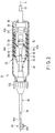
- the treatment device 12 includes a holding portion 22 to be held by a user, an ultrasonic transducer unit 24, a probe 26, and an actuator 28.
- the holding portion 22 has a central axis on a longitudinal axis L defined by the probe 26.
- the ultrasonic transducer unit 24, the probe 26 and a tubular body 30 are arranged to the holding portion 22 at the center of the longitudinal axis L.
- the holding portion 22 includes a tubular outer case 42 preferably having, for example, electric insulating properties.
- a tubular inner case (a cover for the transducer unit) 52 that supports the ultrasonic transducer unit 24 on the inner side of the inner case 52, and the actuator 28 that moves the inner case 52 along the longitudinal axis L.
- the outer case 42 and the inner case 52 are present at concentric positions at the center of the longitudinal axis L, and the actuator 28 is supported at a proximal end of the outer case 42.
- the actuator 28 can move the ultrasonic transducer unit 24 and the probe 26 integrally to the holding portion 22 along the longitudinal axis L at a stroke larger than an amplitude of an ultrasonic vibration to be transmitted to a treatment portion 94 of the probe 26.
- a linear motor 62 having a linear actuating rod 62a is used in this embodiment.
- the linear actuating rod 62a expands and contracts along the longitudinal axis L, whereby the inner case 52 can be moved to the outer case 42 along the longitudinal axis L.
- the inner case 52 is moved by the actuator 28, whereby the ultrasonic transducer unit 24 and the probe 26 are moved by the actuator 28 at the stroke larger than the amplitude (e.g., about several tens ⁇ m) of the ultrasonic vibration to be transmitted to the treatment portion 94 of the probe 26 along the longitudinal axis L of the probe 26.
- a stroke of the linear actuating rod 62a is sufficiently larger than the amplitude of the ultrasonic vibration to be transmitted to the treatment portion 94 of the probe 26.
- a maximum stroke of the linear actuating rod 62a can be from about 10 mm to 20 mm, and can suitably be set in accordance with a performance of the actuator 28 itself and by an after-mentioned setting section 134. It is to be noted that a minimum stroke of the linear actuating rod 62a can be set by the setting section 134, but is larger than the amplitude of the ultrasonic vibration to be transmitted to the treatment portion 94 of the probe 26.
- a ball screw may be combined with a rotary shaft of a rotary motor to directly operate the linear actuating rod 62a, though it is not shown in the drawing. That is, the actuator 28 may only move the ultrasonic transducer unit 24 and the probe 26 integrally to the holding portion 22 along the longitudinal axis L of the probe 26. In this case, the actuator 28 moves the ultrasonic transducer unit 24 and the probe 26 integrally at the stroke larger than the amplitude of the ultrasonic vibration.
- a first bearing 72 is interposed between an inner peripheral surface of the outer case 42 and an outer peripheral surface of the inner case 52.
- the inner case 52 is rotatable to the outer case 42 in a periaxial direction of the longitudinal axis L
- the inner case 52 is rotatable to the outer case 42 in an axial direction along the longitudinal axis L.
- the first bearing 72 may only have a function of moving the inner case 52 to the outer case 42 in the axial direction along the longitudinal axis L.
- the actuator 28 is fixed to the inner side of the outer case 42 and a proximal end of the inner case 52. Between the actuator 28 and the outer case 42, a second bearing 74 such as a ball bearing is interposed, and the inner case 52 is rotatably supported to the actuator 28. It is to be noted that, when the inner case 52 does not have to be rotated to the actuator 28, the second bearing 74 does not have to be disposed.
- the transducer unit 24 and the probe 26 are supported in the inner case 52.
- the transducer unit 24 includes the ultrasonic transducer 82 that generates the ultrasonic vibration by suitably supplying the power from the power source unit 14 shown in FIG. 1 , and a conical horn 84 that enlarges the amplitude of the ultrasonic vibration generated in the ultrasonic transducer 82. That is, the transducer unit 24 generates the ultrasonic vibration in accordance with the supply of the power.
- the ultrasonic transducer 82 for example, a BLT type is used.
- the horn 84 is attached to an external thread 26a of a proximal end of the probe 26 by a connecting screw (an internal thread) 86.
- the horn 84 includes an outer flange 84a projected outwardly in a radial direction to the longitudinal axis L of the horn 84.
- the outer flange 84a is present at a node position of the ultrasonic vibration when the vibration is transmitted from the ultrasonic transducer 82.
- an inner flange 52a projected inwardly from an inner peripheral surface in the radial direction is formed in the inner case 52.
- the outer flange 84a of the horn 84 engages with the inner flange 52a of the inner case 52, whereby the transducer unit 24 and the probe 26 are supported in the inner case 52. That is, the inner case 52 is interposed between the holding portion 22 and the ultrasonic transducer unit 24, to support the ultrasonic transducer unit 24 at the node position of the ultrasonic vibration.
- the ultrasonic transducer unit 24 is supported in the inner case 52, but it is also preferable that the ultrasonic transducer unit 24 is attachable to and detachable from the inner case 52.
- the probe 26 shown in FIG. 1 and FIG. 2 is designed so that an overall length of the probe is an integer multiple of a half wavelength of the ultrasonic vibration.
- the probe 26 includes a rod-like probe main body 92 made of a metal such as a titanium alloy material, and the treatment portion 94 disposed on a distal end side of the probe main body 92. Amplitude of the ultrasonic vibration generated by the ultrasonic transducer 82 is enlarged by the horn 84 and the enlarged amplitude is transmitted to the treatment portion 94 through the probe main body 92.
- the probe 26 is capable of transmitting the ultrasonic vibration from the ultrasonic transducer unit 24, and treating the biological tissue by an action of the ultrasonic vibration transmitted to the treatment portion 94 of a distal end portion of the probe.
- the treatment portion 94 according to this embodiment is formed as a hook type. Further, at an antinode position of the ultrasonic vibration or the vicinity of the position, the treatment portion 94 has a blade surface region 94a to which the ultrasonic vibration is transmitted in a state where the region is allowed to abut on the biological tissue, whereby it is possible to cut the biological tissue on which the region is allowed to abut.
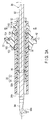
- the tubular body 30 includes a tubular inner sheath 32 and a tubular outer sheath 34.
- the tubular body 30 is disposed on a distal end side of the holding portion 22, to cover an outer periphery of the probe main body 92 of the probe 26 in a state where the treatment portion 94 of the distal end portion of the probe 26 is exposed.
- the inner sheath 32 and the outer sheath 34 are concentrically arranged to the longitudinal axis L.
- the inner sheath 32 covers an outer peripheral surface of the probe 26.
- the outer sheath 34 covers an outer peripheral surface of the inner sheath 32.
- a proximal end of the inner sheath 32 is preferably formed integrally at a distal end of the inner case 52.
- the outer sheath 34 has a length to expose the treatment portion 94 of the distal end portion of the probe 26.
- the inner sheath 32 has a length extending to a distal end of the probe 26 further from the node position generated on the most distal end side of the ultrasonic vibration in the probe. Consequently, a distal end 32a of the inner sheath 32 is positioned on a distal end side from the node position of the most distal end side of the ultrasonic vibration to be transmitted from the ultrasonic transducer unit 24 to the probe 26.
- a sealing body (a first sealing member) 36 made of a rubber material or the like having heat resisting properties and shaped in the form of a ring.
- the sealing body 36 comes in contact closely with the inner peripheral surface of the inner sheath 32 of the tubular body 30 and the outer peripheral surface of the probe 26.
- the sealing body 36 prevents penetration of a liquid from the sealing body (a sealing position) 36 along the longitudinal axis L into a proximal end side, when the liquid penetrates from a distal end side of the inner sheath 32 of the tubular body 30 into a space between the inner peripheral surface of the inner sheath and the outer peripheral surface of the probe 26.
- the sealing body 36 performs a function of a spacer that prevents the inner peripheral surface of the inner sheath 32 of the tubular body 30 from coming in contact with the outer peripheral surface of the probe 26.
- the liquid or the inner sheath 32 is prevented from coming in contact with the probe main body 92 on the proximal end side from the sealing body 36. Further, when the ultrasonic vibration is transmitted to the probe 26, the transmission can be prevented from being obstructed, so that the ultrasonic vibration can suitably be transmitted to the treatment portion 94. In addition, a load can be prevented from being applied to the probe 26 as much as possible.
- the sealing body 36 is disposed at a position corresponding to the node position of the ultrasonic vibration, when the vibration is transmitted from the ultrasonic transducer unit 24 to the probe 26.
- the sealing bodies 36 are preferably disposed at respective node positions, when a length of the probe 26 is regulated so that the node positions of the vibration are present.
- the sealing body 36 is preferably disposed at a position corresponding to the most distal end node position, to prevent the penetration of the liquid into the inner sheath 32 as much as possible. Therefore, the distal end of the inner sheath 32 is positioned on the distal end side further from the position corresponding to the most distal end node position.
- the inner sheath 32 of the tubular body 30 moves together with the probe 26 and the sealing body 36 in accordance with the movement of the actuator 28.
- the inner sheath 32, the probe 26 and the sealing body 36 move in a state where a positional relation among them is substantially unchanged.
- the outer sheath 34 of the tubular body 30 does not move, and hence, the inner sheath 32 is relatively movable to the outer sheath 34 along the axial direction.
- an inner peripheral surface of the outer sheath 34 of the tubular body 30 may be slidable smoothly to the outer peripheral surface of the inner sheath 32 along the longitudinal axis L, or may be separated from the outer peripheral surface of the inner sheath.
- the outer sheath 34 of the tubular body 30 has, at its distal end, an opening 34a which is configured to change a projecting amount to the distal end when the ultrasonic transducer unit 24 and the probe 26 are moved along the longitudinal axis L by the actuator 28.
- a core material of each of the inner sheath 32 and the outer sheath 34 of the tubular body 30 is made of a material such as a stainless alloy material having a rigidity, and each of an outer surface and an inner surface of the core material is preferably coated with a material such as PTFE having electric insulating properties.
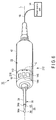
- FIG. 3A and FIG. 3B show a coupling portion of the probe main body 92 and the proximal end of each of the inner sheath 32 and the outer sheath 34 of the tubular body 30 with the holding portion 22.
- a rotary operating knob 102 is attached to the inner case 52 so that the knob is rotatable in the periaxial direction of the longitudinal axis L of the tubular body 30.
- the rotary operating knob 102 is disposed on an outer peripheral side of the outer sheath 34 of the tubular body 30.
- the rotary operating knob 102 is integrally attached to the probe main body 92, the inner case 52 and the tubular body 30.
- a coupling structure of the rotary operating knob 102, the probe main body 92, the inner case 52 and the tubular body 30 is described.
- the rotary operating knob 102 has, in its proximal end portion, a pair of engaging claws 112 projected toward an inner side (the longitudinal axis L).
- the outer sheath 34 of the tubular body 30 has, in its proximal end portion, a pair of engaging holes 114 to be engaged with the engaging claws 112.
- the engaging claws 112 of the rotary operating knob 102 are engaged with the engaging holes 114 of the outer sheath 34 of the tubular body 30, respectively, the outer sheath 34 of the tubular body 30 is attached to the rotary operating knob 102.
- the inner case 52 has, at its distal end portion, i.e., the inner sheath 32 has, at its proximal end portion, a pair of slide holes 116 in which the engaging claws 112 are relatively movable.
- Each of the slide holes 116 is shaped in the form of a long hole that is longer than a thickness of each of the engaging claws 112 along the axial direction of the longitudinal axis L of the probe main body 92.
- the inner sheath 32 i.e., the inner case 52
- the inner sheath 32 and the inner case 52 are relatively movable to the rotary operating knob 102 along the axial direction of the longitudinal axis L.
- the inner sheath 32 of the tubular body 30, i.e., the inner case 52, the outer sheath 34 of the tubular body 30 and the rotary operating knob 102 can integrally be assembled.
- the rotary operating knob 102 when the rotary operating knob 102 is rotated in the periaxial direction of the longitudinal axis L of the probe 26, the outer sheath 34 and the inner sheath 32, i.e., the inner case 52 are integrally rotated in the periaxial direction of the longitudinal axis L together with the rotary operating knob 102. In conjunction with this operation of the inner case 52, the ultrasonic transducer unit 24 and the probe 26 are also rotated integrally with the outer sheath 34 and the inner sheath 32, i.e., the inner case 52 in the periaxial direction of the longitudinal axis L. It is to be noted that, in this embodiment, the rotary operating knob 102 is disposed, but does not necessarily have to be disposed, and the rotary operating knob 102 may suitably be disposed.
- O-rings 122 and 124 that maintain water tightness in the holding portion 22 are interposed between an outer peripheral surface of the outer sheath 34 and an inner peripheral surface of the rotary operating knob 102 and between the outer case 42 and a proximal end surface of the rotary operating knob 102, respectively.
- an O-ring (a second sealing member) 126 is interposed between the outer peripheral surface of the inner sheath 32 and the inner peripheral surface of the outer sheath 34.
- the O-ring 126 is present at a position on the proximal end side from the sealing body 36 along the longitudinal axis L.
- the O-ring 126 maintains the water tightness when the inner sheath 32 moves to the outer sheath 34 along the axial direction of the longitudinal axis L, and maintains the water tightness when the inner sheath 32 rotates to the outer sheath 34 in the periaxial direction of the longitudinal axis L. Further, by an action (a frictional force) of the O-ring 122, the knob 102 and the outer sheath 34 are inhibited from mutually moving.
- the knob 102 and the outer case 42 are inhibited from mutually moving.
- an action (a frictional force) of the O-ring 126 the inner sheath 32 and the outer sheath 34 are inhibited from mutually moving. Therefore, when the user does not operate the knob 102, the knob maintains its position.
- the actuator 28 is not driven, the inner sheath 32 does not move to the outer sheath 34, and relative positions of the sheaths are maintained.
- the O-rings 122 and 126 are disposed in the rotary operating knob 102.
- the rotary operating knob 102 is formed in a larger volume, has a higher rigidity and is harder to be deformed than another region. Consequently, the O-ring 122 is prevented from being shifted from a predetermined position on the outer peripheral surface of the outer sheath 34, and the O-ring 126 is prevented from being shifted from a predetermined position on the inner peripheral surface of the outer sheath 34.
- the O-ring (the second sealing member) 126 enables the positional shift to the inner sheath 32 while maintaining a close contact state with the outer peripheral surface of the inner sheath 32, and the close contact state is maintained while preventing a positional shift to the outer sheath 34.
- the power source unit 14 includes a controller 132, the setting section 134, a power source 136 for the ultrasonic transducer as a first power source that supplies the power to the ultrasonic transducer 82, and a power source 138 for the actuator as a second power source that supplies the power to the actuator 28.
- the controller 132 is electrically connected to the setting section 134, the power source 136 for the ultrasonic transducer and the power source 138 for the actuator.
- the switch portion (the hand switch) 16 is disposed in the holding portion 22.
- the switch portion 16 is preferably formed in an outer peripheral surface of the holding portion 22 in the vicinity of a distal end portion of the holding portion.
- the switch portion 16 includes a first switch 142, a second switch 144, and a third switch 146. It is to be noted that as shown in FIG. 8A of an after-mentioned third embodiment, the third switch 146 of the switch portion 16 is not necessarily required.
- the power source 136 for the ultrasonic transducer is electrically connected to the ultrasonic transducer 82, and the power source 138 for the actuator is electrically connected to the actuator 28.
- the first switch 142, the second switch 144 and the third switch 146 are electrically connected to the controller 132.
- the ultrasonic transducer 82 (the ultrasonic transducer unit 24) and the actuator 28 are controlled by the control section 132 on the basis of information set in the setting section 134 by the user.
- the setting section 134 e.g., a touch panel
- parameters concerning the treatment device 12, the power source unit 14 and the switch portion 16 can suitably be set.
- a control parameter of the ultrasonic transducer 82 and a control parameter of the actuator 28 can suitably be set and stored.
- setting information to be input and stored in the setting section 134 by the user.
- the user can suitably set the power to be supplied from the power source 136 for the ultrasonic transducer to the ultrasonic transducer 82 of the ultrasonic transducer unit 24, by the setting section 134.
- the ultrasonic transducer 82 is preferably set so that the treatment portion 94 of the probe 26 vibrates at a suitable amplitude irrespective of an impedance to be measured by the ultrasonic transducer 82. That is, the power source 136 for the ultrasonic transducer is controlled by the controller 132 so that the power (a voltage) is changed to maintain the amplitude in accordance with a measured value of the impedance.
- the user can suitably set the power to be supplied from the power source 138 for the actuator to the actuator 28, by the setting section 134.
- the user can set control parameters such as a maximum moving amount (stroke) of the actuator 28 and a moving amount (speed) per unit time, by the setting section 134.
- the actuator 28 is preferably controlled by the control section 132 to straight move the treatment portion 94 of the probe 26 along the longitudinal axis L at a suitable stroke and a suitable speed irrespective of the impedance to be measured by the actuator 28. That is, the power source 138 for the actuator is controlled by the control section 132 so that the stroke is suitably maintained in accordance with the measured value of the impedance and so that the power (the voltage) is changed to suitably maintain the moving speed.
- the user can assign functions of the first switch 142, the second switch 144 and the third switch 146 of the switch portion 16, by the setting section 134.
- the setting section 134 is preferably set so that the ultrasonic transducer 82 and the actuator 28 are not driven in a state where the pressed first to third switches 142, 144 and 146 are released.
- the user sets the setting section 134 so that, for example, when the pressed state of the first switch 142 is maintained, the ultrasonic transducer 82 is driven to generate the ultrasonic vibration but the actuator 28 is not driven.
- the user sets the setting section 134 so that, for example, when the pressed states of the second and third switches 144 and 146 are maintained, the ultrasonic transducer 82 is driven to generate the ultrasonic vibration and the actuator 28 is driven.
- the user sets the setting section 134 so that, for example, when the pressed state of the second switch 144 is maintained, the stroke of the actuator 28 is smaller than that when the pressed state of the third switch 146 is maintained. In the state where the third switch 146 is pressed, the stroke becomes comparatively large, and hence, the setting section 134 is preferably set so that the moving speed is lower than that in a state where the second switch 144 is pressed.
- the control section 132 applies the power from the power source 136 for the ultrasonic transducer to the ultrasonic transducer 82, and generates the ultrasonic vibration from the ultrasonic transducer 82. That is, the ultrasonic transducer 82 can be driven. Therefore, the ultrasonic vibration is transmitted from the ultrasonic transducer 82 through the horn 84 to the probe 26, i.e., the ultrasonic vibration is transmitted from the ultrasonic transducer unit 24 to the probe 26. In consequence, a treatment such as cutting of the biological tissue can be performed in the blade surface region 94a of the treatment portion 94 of the probe 26.
- the controller 132 can apply the power from the power source 138 for the actuator to the actuator 28 and drive the actuator 28. Therefore, the linear actuating rod 62a of the linear motor 62 of the actuator 28 moves straight to the holding portion 22 along the longitudinal axis L, and the inner case 52 supporting the ultrasonic transducer unit 24 moves to the holding portion 22 along the longitudinal axis L.
- a position of the opening 34a of a distal end of the tubular body 30 (the outer sheath 34) to the holding portion 22 does not change, and hence, when the treatment portion 94 of the probe 26 moves along the longitudinal axis L, a distal end of the treatment portion 94 separates from and comes close to the distal end of the tubular body 30.
- the user can set the setting section 134 so that, when the pressing is released, the generation of the ultrasonic vibration is simultaneously stopped in the state where the pressed first to third switches 142, 144 and 146 are released.
- the user can set the setting section 134 so that, for example, immediately after the generation of the ultrasonic vibration is stopped, the linear actuating rod 62a of the linear motor 62 of the actuator 28 is moved and returned to the most retracted position at a lower speed than the speed in the state where the second switch 144 or the third switch 146 is pressed.
- the user can set the setting section 134 so that, for example, in a state where the second switch 144 or the third switch 146 continues to be pressed, the vibration of the ultrasonic transducer 82 or the driving of the actuator 28 is stopped immediately after the actuator 28 moves as much as, e.g., one stroke, and in the state where the second switch 144 or the third switch 146 continues to be pressed, the vibration of the ultrasonic transducer 82 and the driving of the actuator 28 continue to be performed.
- the user can set the treatment system 10 by the setting section 134 so that the first switch 142 preferentially operates when the first and second switches 142 and 144 are simultaneously pressed, the second switch 144 preferentially operates when the second and third switches 144 and 146 are simultaneously pressed, the first switch 142 preferentially operates when the first and third switches 142 and 146 are simultaneously pressed, and the first switch 142 preferentially operates when the first to third switches 142, 144 and 146 are simultaneously pressed.
- the user determines a range (a region) of the biological tissue to be cut in accordance with an observation result of the arthroscope 160 or the like. Further, the user suitably sets the speeds of the actuator 28 to be assigned to the second and third switches 144 and 146 (projecting and retracting speeds of the treatment portion 94 of the probe 26), and a control parameter such as the stroke on the basis of the observation result by the setting section 134 of the power source unit 14.
- the stroke to be assigned to the second switch 144 is set to be smaller than the stroke to be assigned to the third switch 146.
- the user observes a direction of the probe 26 to the surface F of the biological tissue by the arthroscope 160 while holding the holding portion 22.
- the user rotates the rotary operating knob 102 to allow the blade surface region 94a of the treatment portion 94 of the probe 26 as needed, to abut on the surface F of the biological tissue.
- the ultrasonic transducer 82 When the pressed second switch 144 is maintained in this state, the ultrasonic transducer 82 is driven, and the ultrasonic vibration is generated from the ultrasonic transducer unit 24, i.e., the unit is driven. At this time, the blade surface region 94a of the treatment portion 94 enters in a depth direction (a direction to cut the biological tissue) from the surface F of the biological tissue by the action of the ultrasonic vibration. Simultaneously with or immediately after the generation of the ultrasonic vibration, the actuator 28 is driven.
- the inner sheath 32 moves forwardly and backwardly along the longitudinal axis L while maintaining a mutual close contact state of the sheaths against the frictional force of the O-ring 126 interposed between the outer peripheral surface of the inner sheath and the inner peripheral surface of the outer sheath 34. That is, the blade surface region 94a of the treatment portion 94 moves along the longitudinal axis L as much as a moving amount D that is the same amount as a moving amount D of the linear actuating rod 62a along the longitudinal axis L of the actuator 28.
- the distal end of the treatment portion 94 of the probe 26 moves toward the arthroscope 160 while cutting the surface F of the biological tissue, and then the distal end separates from the arthroscope 160 while cutting the surface F of the biological tissue. That is, the blade surface region 94a moves in a region shown by reference sign H in FIG. 5 .
- the distal end of the treatment portion 94 of the probe 26 moves toward the arthroscope 160 again while cutting the surface F of the biological tissue, and then the distal end separates again from the arthroscope 160 while cutting the surface F of the biological tissue. That is, the blade surface region 94a reciprocates in the region shown by the reference sign H in FIG. 5 .
- the outer sheath 34 and the O-ring 126 do not move, and the inner sheath 32 moves along the longitudinal axis L while the outer peripheral surface of the inner sheath is in contact closely with the O-ring 126. That is, a position of the inner sheath 32 is shifted to the outer sheath 34 by driving the actuator 28. On the other hand, the inner sheath 32 moves together with the probe 26. In consequence, even when the actuator 28 is driven, a position of the sealing body 36 does not shift to the probe 26 and the inner sheath 32.
- the actuator 28 moves the ultrasonic transducer unit 24, the probe 26, and the inner sheath 32 integrally to the outer sheath 34 along the longitudinal axis L at the stroke larger than the amplitude of the ultrasonic vibration to be transmitted to the treatment portion 94 of the probe 26.
- the user needs to allow the blade surface region 94a of the treatment portion 94 of the probe 26 to abut on the surface F of the biological tissue.
- a position of the holding portion 22 is simply fixed to the surface F of the biological tissue, for example, an angle of the blade surface region 94a changes, so that the cutting is hard to be stably performed.
- the user moves the holding portion 22 substantially orthogonally to the longitudinal axis L as shown by reference sign V so that the angle of the blade surface region 94a of the treatment portion 94 of the probe 26 by the actuator 28 is suitably maintained.
- the holding portion 22 it is not necessary to move the holding portion 22 along the longitudinal axis L (a substantially three-dimensional movement is not required), but if necessary, the holding portion may only be moved in a direction substantially orthogonal to the longitudinal axis L as shown by the reference sign V.
- the holding portion 22 is substantially two-dimensionally moved, whereby a region of the biological tissue along a substantially linearly set distance can be cut without manually moving the holding portion 22 in the direction along the longitudinal axis L.
- the user cuts the biological tissue while confirming a cut state of the tissue by the arthroscope 160. Further, when it is confirmed that the biological tissue is cut by the ultrasonic vibration as much as a desirable amount, the pressed second switch 144 is released. Consequently, the driving of the ultrasonic transducer 82 is stopped. Immediately after the driving is stopped, the inner case 52, the ultrasonic transducer unit 24 and the probe 26 move to the holding portion 22 to be stopped so that the distal end of the treatment portion 94 comes closest to the distal end of the tubular body 30 by the operation of the actuator 28.
- a treatment such as the cutting of the surface F of the biological tissue can be performed in this manner.
- the ultrasonic transducer 82 is driven, but the actuator 28 is not driven. Consequently, the holding portion 22 is suitably moved in the direction along the longitudinal axis L and the abovementioned direction shown by the reference sign V, whereby the cutting of the biological tissue or the like can suitably be performed.
- the ultrasonic transducer 82 is driven, and the treatment portion 94 of the probe 26 can be moved at a stoke larger than that in a case where the pressed state of the second switch 144 is maintained by the actuator 28. Consequently, when the pressed state of the third switch 146 is maintained, a larger range of the biological tissue can be cut than the range in the case where the pressed state of the second switch 144 is maintained. That is, when the third switch 146 is pressed to be operated, an operation amount of the actuator 28 can be changed as compared with a case where the second switch 144 is pressed to be operated.
- an initial position of the treatment portion 94 of the probe 26 to the tubular body 30 (a projecting position of the treatment portion 94 from the distal end of the tubular body 30 in a state where the ultrasonic transducer 82 and the actuator 28 are not driven) is set as a position of the treatment portion 94 brought closest to the distal end opening 34a of the tubular body 30.
- the setting section 134 can set the initial position of the treatment portion 94 of the probe 26 to the tubular body 30 as a position of the treatment portion 94 most separated from the distal end opening 34a of the tubular body 30.
- the initial position can be set as a position between the closest position and the most separated position.
- the sealing body 36 is interposed between the outer peripheral surface of the probe 26 and the inner peripheral surface of the inner sheath 32, whereby the penetration of the liquid onto the proximal end side of the probe 26 from the position (the sealing position) of the sealing body 36 is prevented, and the outer peripheral surface of the probe 26 is separated from the inner peripheral surface of the inner sheath 32.
- a space between the outer peripheral surface of the inner sheath 32 and the inner peripheral surface of the outer sheath 34 is sealed with the O-ring (a sealing body) 126, and the liquid is prevented from penetrating into the outer peripheral surface of the probe 26 and the ultrasonic transducer unit 24.
- the inner sheath 32 or the liquid is prevented from being brought into contact with a region other than the treatment portion 94 of the probe 26 to which the vibration is transmitted, and thus, a load is prevented from being applied to the region as much as possible.
- the ultrasonic transducer 82 and the actuator 28 are driven. Consequently, the treatment portion 94 can straight be moved in the state where the treatment portion 94 of the probe 26 is allowed to abut on the biological tissue. Therefore, according to the treatment device 12 of this embodiment, the treatment, e.g., the cutting of the biological tissue can straight be performed in the desirable range.
- the user hardly needs to move the position of the holding portion 22 in the axial direction of the longitudinal axis L, and may only maintain the state where the blade surface region 94a of the treatment portion 94 is allowed to abut on the surface F of the biological tissue, and hence, the user is hard to be tired. Therefore, according to this embodiment, there can be provided the treatment device 12 in which the user is hard to be tired when performing a treatment such as the cutting of the biological tissue, and the treatment system 10.
- the region can be directed in a desirable direction by rotating the rotary operating knob 102. Consequently, the holding portion 22 can continue to be held without changing the position of the switch portion 16 to the holding portion 22. In consequence, even when the biological tissue is a curved surface or the like, the state where the blade surface region 94a is allowed to abut on the biological tissue can easily be maintained, and the treatment can smoothly be performed.
- the sealing body 36 is interposed between the outer peripheral surface of the probe 26 and the inner peripheral surface of the inner sheath 32, and hence, the penetration of the liquid onto the proximal end side of the probe 26 from the position (the sealing position) of the sealing body 36 can be prevented.
- the space between the outer peripheral surface of the inner sheath 32 and the inner peripheral surface of the outer sheath 34 is sealed with the O-ring (the sealing body) 126, so that the liquid can be prevented from penetrating into the outer peripheral surface of the probe 26 and the ultrasonic transducer unit 24. In consequence, the load can be prevented from being applied to the region other than the treatment portion 94 of the probe 26 to which the vibration is transmitted.
- the power source 136 is controlled by the control section 132 so that the voltage is changed for the ultrasonic transducer unit 24 to maintain a constant amplitude, but the change of the voltage in this case can be inhibited.
- This embodiment is a modification of the first embodiment, and the same members or members having the same functions as in members described in the first embodiment are denoted with the same reference signs as many as possible to omit descriptions of the members.
- a probe 26 according to this embodiment does not rotate to an outer case 42 of a holding portion 22.
- a switch portion 16 is rotatably disposed to the outer case 42 of the holding portion 22 in a periaxial direction of a longitudinal axis (a central axis) L.
- the switch portion 16 includes a ring body 216 rotatable to the outer case 42 in a peripheral direction C that is the periaxial direction of the longitudinal axis L.
- first to third switches 142, 144 and 146 are disposed in the ring body 216.
- a tubular portion 244 projecting to the longitudinal axis L outwardly in a radial direction is formed at a distal end of the tubular portion 244.
- An outer flange 246 is formed at a distal end of the tubular portion 244.
- a fitting groove 218 is formed into which the outer flange 246 is fitted. Consequently, the ring body 216 is rotatable to the outer case 42 in the periaxial direction of the longitudinal axis L.
- the first to third switches 142, 144 and 146 also rotate together.
- a proximal end of an outer sheath 34 of the tubular body 30 is fixed.
- the outer sheath 34 also rotates together with the first to third switches 142, 144 and 146.
- an O-ring (a second sealing member) 126 is interposed between an outer peripheral surface of an inner sheath 32 and an inner peripheral surface of the outer sheath 34
- an O-ring (a second sealing member) 228 is interposed between the outer flange 246 of the distal end of the outer case 42 and the fitting groove 218 of an inner peripheral surface of the ring body 216.
- a user directs a blade surface region 94a of a treatment portion 94 of the probe 26 to a surface F of a biological tissue while holding the holding portion 22.
- the switch portion 16 is rotated to the holding portion 22 along the peripheral direction C, and the first to third switches 142, 144 and 146 are maintained at positions easy to be operated by the user.
- the holding portion 22 and the ring body 216 are held.
- the outer sheath 34 and the O-ring 126 do not move, but the inner sheath moves along the longitudinal axis L against a frictional force while the outer peripheral surface of the inner sheath 32 is in contact closely with the O-ring 126. That is, a position of the inner sheath 32 is shifted to the outer sheath 34 by driving the actuator 28.
- the inner sheath 32 moves together with the probe 26. In consequence, even when the actuator 28 is driven, a position of a sealing body 36 is not shifted to the probe 26 and the inner sheath 32.
- the treatment device 212 can be used substantially similarly to the treatment device 12 described in the first embodiment. That is, an operation of cutting, for example, a bone or a cartilate can be performed while preventing a liquid or an inner peripheral surface of the inner sheath 32 from being adhered to the probe 26 as much as possible and preventing a load due to the adhering of the liquid to the probe 26 to which an ultrasonic vibration is transmitted.
- This embodiment is a modification of the first and second embodiments, and the same members or members having the same functions as in members described in the first and second embodiments are denoted with the same reference signs as many as possible to omit descriptions of the members.
- the foot switch 16a has first and second switches 142 and 144 to which a function similar to that of the switch portion 16 described in the first and second embodiments is assigned. That is, the number of the switches may be three or two. However, there are preferably present a switch that does not drive an actuator 28 but drives an ultrasonic transducer 82 and a switch that drives the actuator 28 as well as the ultrasonic transducer 82.
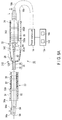
- the holding portion 22 includes a tubular body 342 in which the transducer unit 24 and the probe 26 are disposed at positions where a longitudinal axis L passes and the actuator 28 is disposed on an inner side.
- the transducer unit 24 and the probe 26 are movable to the tubular body 342 of the holding portion 22 along the longitudinal axis L, and the actuator 28 is fixed to the tubular body 342 of the holding portion 22.
- the actuator 28 of the treatment device 312 according to this embodiment is fixed to the tubular body 342 of the holding portion 22 at a position disposed away from the longitudinal axis L. That is, here, the arrangement of the actuator 28 is different from that of the first and second embodiments.
- a proximal end of an outer sheath 34 of a tubular body 30 of this embodiment is fixed to a distal end of the tubular body 342 of the holding portion 22.
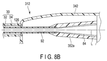
- a proximal end of an inner sheath 32 is fixed to an inner peripheral surface of a distal end of a tubular body 352a of an after-mentioned cover 352. Consequently, the inner sheath 32 moves together with the ultrasonic transducer unit 24 and the probe 26 by an actuation of the actuator 28, but the outer sheath 34 does not move together with the ultrasonic transducer unit 24 and the probe 26.
- FIG. 8A there is disposed a sealing body 36 that seals a space between an inner peripheral surface of the inner sheath 32 and an outer peripheral surface of the probe 26 and prevents a liquid from penetrating from a sealing position to the outer peripheral surface of the probe 26 along the longitudinal axis L on a proximal end side.
- a sealing body 36 that seals a space between an inner peripheral surface of the inner sheath 32 and an outer peripheral surface of the probe 26 and prevents a liquid from penetrating from a sealing position to the outer peripheral surface of the probe 26 along the longitudinal axis L on a proximal end side.
- FIG. 8B there is disposed an O-ring 126 that seals a space between an outer peripheral surface of the inner sheath 32 and an inner peripheral surface of the outer sheath 34 and prevents the liquid from penetrating into the outer peripheral surface of the probe 26 and the ultrasonic transducer unit 24.
- the O-ring 126 is disposed on an inner side of a distal end portion of the tubular body 342.
- the tubular body 342 is formed in a larger volume, has a higher rigidity and is harder to be deformed than another region. In consequence, even when the inner sheath 32 is moved to the outer sheath 34 along the longitudinal axis L, the O-ring 126 is prevented from being shifted from a predetermined position on the inner peripheral surface of the outer sheath 34.
- one cable 18 that supplies a power to the ultrasonic transducer unit 24 and the actuator 28 and further transmits a signal to the first and second switches 142 and 144 and receives a signal from the switches is extended from a proximal end portion of an outer case 42 of the holding portion 22.
- a cable 18a for the transducer is extended from the ultrasonic transducer unit 24 to be attachably and detachably connected to the power source unit 14.
- a cable 18b for the actuator is extended from the actuator 28 to be attachably and detachably connected to the power source unit 14.
- the foot switch 16a is connected to the power source unit 14, and hence, the signals of the first and second switches 142 and 144 do not have to be transmitted or received from the treatment device 312 to the power source unit 14.
- the cables 18a and 18b are made of a material having a flexibility. As the material of the cables 18a and 18b and concerning a signal line in each cable, a softer material having a higher flexibility is preferably selected.
- the tubular cover (the cover for the transducer unit) 352 is disposed on an outer periphery of the ultrasonic transducer unit 24, the tubular cover (the cover for the transducer unit) 352 is disposed. A side surface of the cover 352 is supported movably in parallel with the longitudinal axis L by after-mentioned sliders 362a and 362b of the actuator 28 fixed to the holding portion 22.
- a linear motor may be used as described in the first embodiment, and a rotary motor including a ball screw attached to a rotary shaft may be used.
- the actuator 28 has the plural sliders 362a and 362b (two sliders are described here) that perform a linear motion into which a rotary motion of the motor is converted by an operation of the ball screw.
- the ultrasonic transducer unit 24 and the probe 26 are supported by the cover 352.
- the cover 352 supports the ultrasonic transducer unit 24 similarly to the inner case 52 described in the first embodiment.
- the cover 352 has the distal end tube 352a that covers an outer periphery of a horn 84 at a distal end of the cover 352.
- the distal end tube 352a is formed to be tapered toward a distal end side while maintaining a state where an inner peripheral surface of the distal end tube 352a is separated from the horn 84.
- the proximal end of the inner sheath 32 is integrally and water-tightly fixed to the distal end of the tubular body 352a.
- the cover 352 moves to the holding portion 22 along the longitudinal axis L.
- the ultrasonic transducer unit 24 and the probe 26 also move to the holding portion 22 along the longitudinal axis L together with the cover 352.
- the cover 352 in which the probe 26 and the ultrasonic transducer unit 24 are supported linearly performs a one-way motion or a reciprocating motion once or plural times between a broken line position and a solid line position.
- the outer sheath 34 and the O-ring 126 do not move, and the inner sheath 32 moves along the longitudinal axis L together with the probe 26 while the outer peripheral surface of the inner sheath is in contact closely with the O-ring 126.
- the treatment device 312 can be used by driving the actuator 28 in the same manner as in the treatment device 12 described in the first embodiment. It is to be noted that when the first switch 142 of the foot switch 16a is pressed, needless to say, the treatment device 312 can be used in the same manner as in the treatment device 12 described in the first embodiment.
- the tubular body 342 of the holding portion 22 is rotated in a periaxial direction of the longitudinal axis L.
- the cables 18a and 18b have a flexibility, and hence, when a softer material having a higher flexibility is selected as a material of the cables 18a and 18b and concerning a signal line in each cable, an influence on a user maintaining a position of the holding portion 22 can almost be ignored.
- the switch portion 16 as a hand switch described in the first and second embodiments is also preferably used.
- the switch portion 16 having the ring body 216 described in the second embodiment is also preferably used.
- the longitudinal axis L of the ultrasonic transducer unit 24 and the probe 26 does not match a central axis of the tubular body 342 of the holding portion 22 (a central axis of the ring body 216) in a certain case, but the ring body 216 may only rotate in a periaxial direction of the central axis of the tubular body 342 of the holding portion 22 (the central axis of the ring body 216).
- this embodiment has been described on the assumption that an arrangement of the actuator 28 is different from that of the actuator 28 described in the first and second embodiments, but needless to say, the actuator 28 described in the first and second embodiments may be used as it is.
- This embodiment is a modification of the first to third embodiments, and the same members or members having the same functions as in members described in the first to third embodiments are denoted with the same reference signs as many as possible to omit descriptions of the members. It is to be noted that this embodiment is an example where a foot switch 16a has first to third switches 142, 144 and 146.
- a treatment device 412 includes a tubular body 430 that is different from the tubular body 30 of each of the treatment devices 12 and 312 described in the first and third embodiments.
- the tubular body 430 includes an inner sheath 32 and an outer sheath 434.
- a distal end of the outer sheath 434 of the tubular body 430 is closed, and an opening 434a is formed in a side surface of the outer sheath in the vicinity of a distal end portion of the outer sheath 434.
- a blade surface region 94a of a treatment portion 94 of a distal end portion of a probe 26 is positioned on a slightly outer side of the tubular body 430 than the opening 434a. That is, in a side surface of a distal end portion of the tubular body 430, the tubular body includes the opening 434a through which the treatment portion 94 of the distal end portion of the probe 26 is exposed.
- the opening 434a is preferably formed to be longer in a direction parallel to a longitudinal axis L than in a peripheral direction.
- an actuator 28 is set and controlled by a setting section 134 so that the treatment portion 94 is movable and does not abut on a distal edge portion 435a and a proximal edge portion 435b of the opening 434a of the tubular body 430.
- the treatment device 412 according to this embodiment can be used in the same manner as in the treatment device 312 described in the third embodiment. That is, when the second switch 144 or the third switch 146 of the foot switch 16a is pressed, the treatment device 412 can be used in the same manner as in the treatment device 12 described in the first embodiment. It is to be noted that when the first switch 142 of the foot switch 16a is pressed, needless to say, the treatment device 412 can be used in the same manner as in the treatment device 12 described in the first embodiment.
- the distal end of the tubular body 430 is closed, and hence, even when a distal end of the tubular body 430 is allowed to abut on a biological tissue such as a bone in a state where an ultrasonic vibration is transmitted to the probe 26, the treatment portion 94 does not abut.
- This embodiment is a modification of the first to fourth embodiments, and the same members or members having the same functions as in members described in the first to fourth embodiments are denoted with the same reference signs as many as possible to omit descriptions of the members. It is to be noted that this embodiment is described on the assumption that a switch portion 16 as a hand switch is disposed in a holding portion 22.
- a treatment device 512 includes a tubular body 530 that is different from the tubular body 30 of each of the treatment devices 12 and 312 described in the first and third embodiments and the tubular body 430 of the treatment device 412 described in the fourth embodiment.
- the tubular body 530 includes an inner sheath 32 and an outer sheath 534.
- a distal end portion of the outer sheath 534 is capable of performing a treatment with an exposed blade surface region 94a, but the distal end portion protects a distal end of a treatment portion 94 and a back surface side to the blade surface region 94a.
- an inner case 52 in which a transducer unit 24 is disposed, a probe main body 92 and an inner sheath 32 of the tubular body 530 in which the probe main body 92 is inserted can be moved in a predetermined range along a longitudinal axis L by an actuator 28 disposed in an outer case 42 in the same manner as described in the first embodiment.
- the treatment device 512 includes an opening 42a formed in the vicinity of a distal end portion of the outer case 42, and a lever (a rotary body) 502 rotatable in a periaxial direction of the longitudinal axis L in the predetermined range.
- the lever 502 is integrated with the inner case 52 and the inner sheath 32. Consequently, when the lever 502 is rotated in the periaxial direction of the longitudinal axis L, the ultrasonic transducer unit 24 and a probe 26 also rotate together with the inner case 52 and the inner sheath 32.
- the lever 502 is movable in the opening 42a in parallel with the longitudinal axis L by the actuator 28. This movement of the lever 502 along the longitudinal axis L appears as a movement of the treatment portion 94 shown from FIG. 10A to FIG. 10B and/or a movement shown from FIG. 10B to FIG. 10A .
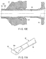
- the outer case 42 has a pair of end faces 42b that define a rotating range of the lever 502. Consequently, the lever 502 rotates in the predetermined range. In FIG. 10C , the lever 502 is rotatable as much as about 180o.
- a proximal end of the outer sheath 534 of the tubular body 530 is fixed to a distal end of the outer case 42.
- the distal end portion of the outer sheath 534 has an opening 534a in a part of a distal end of the outer sheath 534 to a side surface thereof. Consequently, when the lever 502 is rotated in the periaxial direction of the longitudinal axis L, the treatment portion 94 of the probe 26 can be rotated in the periaxial direction of the longitudinal axis L of the treatment portion to expose and hide the blade surface region 94a while protecting the distal end of the treatment portion 94. In consequence, by this rotation of the lever 502, the lever 502 can be directed in a suitable direction to the opening 534a of the distal end portion of the outer sheath 534 of the blade surface region 94a of the treatment portion 94.
- a sealing body 36 as a first sealing member is interposed between an outer peripheral surface of the probe main body 92 of the probe 26 and an inner peripheral surface of the inner sheath 32. Consequently, a liquid is prevented from penetrating from the treatment portion 94 of the probe 26 along the inner peripheral surface of the inner sheath 32 and the outer peripheral surface of the probe main body 92 onto a proximal end side of the sealing body 36, and the inner peripheral surface of the inner sheath 32 is prevented from being brought into contact with the outer peripheral surface of the probe main body 92.
- an O-ring 126 as a second sealing member is interposed between an outer peripheral surface of the inner sheath 32 and an inner peripheral surface of the outer case 42. That is, the O-ring 126 according to this embodiment does not directly come in contact with an inner peripheral surface of the outer sheath 534. Even when the O-ring 126 is formed in this manner, the O-ring can seal a space between the outer peripheral surface of the inner sheath 32 and the inner peripheral surface of the outer sheath 534.
- the O-ring 126 is disposed on an inner side of the distal end portion of the outer case 42.
- the outer case 42 is formed in a larger volume, has a higher rigidity, and is harder to be deformed than another region.
- the O-ring 126 here is disposed in the holding portion 22, a position of the O-ring can be shifted to the inner sheath 32 while maintaining a close contact state with the outer peripheral surface of the inner sheath 32, and the close contact state is maintained while preventing the positional shift of the O-ring to the holding portion 22.
- the actuator 28 is operated by suitably operating the switch portion 16 shown in FIG. 10A and FIG. 10B , whereby the distal end of the treatment portion 94 can be moved between a position shown in FIG. 10A and a position shown in FIG. 10B .
- the outer case 42, the outer sheath 534 and the O-ring 126 do not move, but the inner sheath 32 moves along the longitudinal axis L while the outer peripheral surface of the inner sheath is in contact closely with the O-ring 126. That is, a position of the outer sheath 534 is shifted to the inner sheath 32 by driving the actuator 28.
- the inner sheath 32 moves together with the probe 26. Consequently, a position of the sealing body 36 is not shifted to the probe 26 and the inner sheath 32 even by driving the actuator 28. In consequence, a load is prevented from being applied to the proximal end side of the sealing body 36 in the probe 26 as much as possible.
- a predetermined range of a bone, a cartilage or the like can be cut without moving the holding portion 22. It is to be noted that at this time, the lever 502 also moves along the longitudinal axis L between the openings 42a of the outer case 42.
- a solenoid may be interposed between the outer peripheral surface of the inner case 52 or the cover 352 and the inner peripheral surface of the outer case 42 or the tubular body 342, and the inner case 52 or the cover 352 may be moved to the outer case 42 or the tubular body 342 in the axial direction of the longitudinal axis L by a magnetic force.
- the treatment portion 94 of the first to fifth embodiments is the hook type.
- the treatment portion 94 may be formed as a rake type.
- a blade surface region 94a of the rake type of treatment portion 94 is formed in a suitable range in a direction orthogonal to a longitudinal axis L.
- the blade surface region 94a is allowed to abut on a surface F of a biological tissue, so that a treatment can be performed by suitably using the treatment devices 12, 212, 312, and 412 described in the first to fifth embodiments.
- the treatment portion 94 may be formed as a curette type.
- a blade surface region 94a of the curette type of treatment portion 94 is formed in a ring shape.
- the blade surface region 94a is allowed to abut on a surface F of a biological tissue, whereby a treatment can be performed by suitably using the treatment devices 12, 212 and 312 described in the first to third embodiments.
- an opening 34a is regulated, whereby the treatment can be performed also by suitably using the treatment device 412 described in the fourth and fifth embodiments.
- the treatment portions 94 shown in FIG. 11A and FIG. 11B are suitable for a treatment of cutting a joint cartilate in the in the same manner as in the treatment portion 94 described in the first to fifth embodiments.
- the treatment portion 94 may be formed as a blade type.
- a blade surface region 94a of the blade type of treatment portion 94 is substantially formed into a U-shape.
- the blade surface region 94a is allowed to abut on a surface F of a biological tissue, whereby a treatment can be performed by suitably using the treatment devices 12, 212, 312, 412 and 512 described in the first to fifth embodiments.
- the treatment portion 94 shown in FIG. 11C is suitable for a treatment of cutting and removing an articular capsule or an articular lip.
- treatment portions 94 having various shapes are usable.
Landscapes
- Health & Medical Sciences (AREA)
- Life Sciences & Earth Sciences (AREA)
- Surgery (AREA)
- Engineering & Computer Science (AREA)
- Public Health (AREA)
- Animal Behavior & Ethology (AREA)
- Veterinary Medicine (AREA)
- General Health & Medical Sciences (AREA)
- Biomedical Technology (AREA)
- Heart & Thoracic Surgery (AREA)
- Nuclear Medicine, Radiotherapy & Molecular Imaging (AREA)
- Medical Informatics (AREA)
- Molecular Biology (AREA)
- Dentistry (AREA)
- Oral & Maxillofacial Surgery (AREA)
- Orthopedic Medicine & Surgery (AREA)
- Mechanical Engineering (AREA)
- Pathology (AREA)
- Radiology & Medical Imaging (AREA)
- Vascular Medicine (AREA)
- Biophysics (AREA)
- Optics & Photonics (AREA)
- Physics & Mathematics (AREA)
- Gynecology & Obstetrics (AREA)
- Epidemiology (AREA)
- Anesthesiology (AREA)
- Hematology (AREA)
- Surgical Instruments (AREA)
Abstract
Description
- This invention relates to a treatment device for use in treating a biological tissue, and a treatment system having the treatment device.
- For example, in a publication of
Jpn. PCT National Publication No. 2013-519434 - Patent Literature 1:
Jpn. PCT National Publication No. 2013-519434 - In an ultrasonic treatment device of a publication of
Jpn. PCT National Publication No. 2013-519434 Jpn. PCT National Publication No. 2013-519434 - Thus, an object of this invention is to provide a treatment device and a treatment system which is capable of moving a probe to a sheath in an axial direction of the probe, and preventing an ultrasonic vibration of the probe from being obstructed.
- According to one aspect of the present invention, a treatment device for use in treating a biological tissue, includes: a holding portion to be held by a user; an ultrasonic transducer unit that generates an ultrasonic vibration in accordance with a supply of a power; a probe which defines a longitudinal axis, is configured to transmit the ultrasonic vibration generated by the ultrasonic transducer unit, and has a treatment portion configured to treat the biological tissue by an action of the ultrasonic vibration transmitted to a distal end portion of the probe; an inner sheath that covers an outer peripheral surface of the probe; a first sealing member that is interposed between an inner peripheral surface of the inner sheath and the outer peripheral surface of the probe, and comes in contact closely with the inner peripheral surface of the inner sheath and the outer peripheral surface of the probe to prevent penetration of a liquid; an outer sheath that covers an outer peripheral surface of the inner sheath; a second sealing member that is interposed between the outer peripheral surface of the inner sheath and an inner peripheral surface of the outer sheath, and comes in contact closely with the outer peripheral surface of the inner sheath and the inner peripheral surface of the outer sheath to prevent the penetration of the liquid; and an actuator that moves the ultrasonic transducer unit, the probe and the inner sheath integrally to the outer sheath along the longitudinal axis at a stroke larger than an amplitude of the ultrasonic vibration to be transmitted to the treatment portion of the probe.
- According to the present invention, there can be provided a treatment device and a treatment system which is capable of moving a probe to a sheath in an axial direction of the probe and preventing an ultrasonic vibration of the probe from being obstructed.
-
-
FIG. 1 is a schematic view showing a treatment system according to a first embodiment; -
FIG. 2 is a schematic partial vertical cross-sectional view of a treatment device of the treatment system according to the first embodiment; -
FIG. 3A is a schematic partial vertical cross-sectional view showing a portion from the vicinity of a rotary operating knob to a distal end side in the treatment device of the treatment system according to the first embodiment; -
FIG. 3B is a schematic lateral cross-sectional view taken along the 3B-3B line inFIG. 3A ; -
FIG. 4 is a schematic block diagram showing the treatment system according to the first embodiment; -
FIG. 5 is a schematic view showing that a biological tissue is moved to be cut in a blade surface region of a probe of the treatment device of the treatment system according to the first embodiment; -
FIG. 6 is a schematic view showing a treatment system according to a second embodiment; -
FIG. 7 is a partial vertical cross-sectional view showing a schematic structure of a treatment device of the treatment system according to the second embodiment; -
FIG. 8A is a schematic partial vertical cross-sectional view showing a treatment system according to a third embodiment; -
FIG. 8B is a schematic enlarged view of a position shown by reference sign 8B in a treatment device shown inFIG. 8A of the treatment system according to the third embodiment; -
FIG. 9 is a schematic partial vertical cross-sectional view showing a treatment system according to a fourth embodiment; -
FIG. 10A is a schematic partial vertical cross-sectional view showing a treatment device according to a fifth embodiment; -
FIG. 10B is a schematic partial vertical cross-sectional view showing the treatment device according to the fifth embodiment; -
FIG. 10C is a schematic partial vertical cross-sectional view of the treatment device according to the fifth embodiment taken along the 10C-10C line inFIG. 10A andFIG. 10B ; -
FIG. 10D is a schematic enlarged view of the treatment device according to the fifth embodiment at a position shown byreference sign 10D inFIG. 10A ; -
FIG. 10E is a schematic enlarged view of the treatment device according to the fifth embodiment at a position shown byreference sign 10E inFIG. 10A ; -
FIG. 11A is a schematic perspective view showing a rake type of treatment portion of a probe which is usable in the first to fifth embodiments; -
FIG, 11B is a schematic perspective view showing a curette type of treatment portion of the probe which is usable in the first to fifth embodiments; and -
FIG. 11C is a schematic perspective view showing a blade type of treatment portion of the probe which is usable in the first to fifth embodiments. - Hereinafter, embodiments of this invention will be described with reference to the drawings.
- A first embodiment is described with reference to
FIG. 1 to FIG. 5 . - As shown in
FIG. 1 , atreatment system 10 according to this embodiment includes atreatment device 12 for use in treating a biological tissue, a power source unit (a controller) 14, and aswitch portion 16 such as a foot switch or a hand switch. Thetreatment device 12 is connected to thepower source unit 14 via acable 18. Through thecable 18, theswitch portion 16 transmits a signal to thepower source unit 14 and receives a signal from the power source unit, and supplies a power controlled by thepower source unit 14 to an after-mentionedultrasonic transducer 82 of thetreatment device 12. It is to be noted that, in the present embodiment, thecable 18 is extended from a proximal end of thetreatment device 12, and an unshown connector of a distal end of thecable 18 is attachable to and detachable from thepower source unit 14. - Additionally, in the present embodiment, as the
switch portion 16, the hand switch disposed in thetreatment device 12 itself is used, but as described later in a third embodiment (seeFIG. 8A ) and a fourth embodiment (seeFIG. 9 ), afoot switch 16a to be connected to thepower source unit 14 is preferably used. Thefoot switch 16a is also attachable to and detachable from thepower source unit 14 in the same manner as in thetreatment device 12. - As shown in
FIG. 2 , thetreatment device 12 includes a holdingportion 22 to be held by a user, anultrasonic transducer unit 24, aprobe 26, and anactuator 28. - In this embodiment, the holding
portion 22 has a central axis on a longitudinal axis L defined by theprobe 26. Theultrasonic transducer unit 24, theprobe 26 and atubular body 30 are arranged to the holdingportion 22 at the center of the longitudinal axis L. - The holding
portion 22 includes a tubularouter case 42 preferably having, for example, electric insulating properties. On an inner side of theouter case 42, there are arranged a tubular inner case (a cover for the transducer unit) 52 that supports theultrasonic transducer unit 24 on the inner side of theinner case 52, and theactuator 28 that moves theinner case 52 along the longitudinal axis L. In this embodiment, theouter case 42 and theinner case 52 are present at concentric positions at the center of the longitudinal axis L, and theactuator 28 is supported at a proximal end of theouter case 42. - The
actuator 28 can move theultrasonic transducer unit 24 and theprobe 26 integrally to the holdingportion 22 along the longitudinal axis L at a stroke larger than an amplitude of an ultrasonic vibration to be transmitted to atreatment portion 94 of theprobe 26. As theactuator 28, alinear motor 62 having alinear actuating rod 62a is used in this embodiment. In thelinear motor 62, thelinear actuating rod 62a expands and contracts along the longitudinal axis L, whereby theinner case 52 can be moved to theouter case 42 along the longitudinal axis L. In other words, theinner case 52 is moved by theactuator 28, whereby theultrasonic transducer unit 24 and theprobe 26 are moved by theactuator 28 at the stroke larger than the amplitude (e.g., about several tens µm) of the ultrasonic vibration to be transmitted to thetreatment portion 94 of theprobe 26 along the longitudinal axis L of theprobe 26. A stroke of thelinear actuating rod 62a is sufficiently larger than the amplitude of the ultrasonic vibration to be transmitted to thetreatment portion 94 of theprobe 26. For example, a maximum stroke of thelinear actuating rod 62a can be from about 10 mm to 20 mm, and can suitably be set in accordance with a performance of theactuator 28 itself and by an after-mentionedsetting section 134. It is to be noted that a minimum stroke of thelinear actuating rod 62a can be set by thesetting section 134, but is larger than the amplitude of the ultrasonic vibration to be transmitted to thetreatment portion 94 of theprobe 26. - As the
actuator 28 according to this embodiment, needless to say, a ball screw may be combined with a rotary shaft of a rotary motor to directly operate thelinear actuating rod 62a, though it is not shown in the drawing. That is, theactuator 28 may only move theultrasonic transducer unit 24 and theprobe 26 integrally to the holdingportion 22 along the longitudinal axis L of theprobe 26. In this case, theactuator 28 moves theultrasonic transducer unit 24 and theprobe 26 integrally at the stroke larger than the amplitude of the ultrasonic vibration. - A
first bearing 72 is interposed between an inner peripheral surface of theouter case 42 and an outer peripheral surface of theinner case 52. By thefirst bearing 72, theinner case 52 is rotatable to theouter case 42 in a periaxial direction of the longitudinal axis L, and theinner case 52 is rotatable to theouter case 42 in an axial direction along the longitudinal axis L. It is to be noted that, when theinner case 52 does not have to be rotated to theouter case 42 in the periaxial direction of the longitudinal axis L, thefirst bearing 72 may only have a function of moving theinner case 52 to theouter case 42 in the axial direction along the longitudinal axis L. - The
actuator 28 is fixed to the inner side of theouter case 42 and a proximal end of theinner case 52. Between theactuator 28 and theouter case 42, asecond bearing 74 such as a ball bearing is interposed, and theinner case 52 is rotatably supported to theactuator 28. It is to be noted that, when theinner case 52 does not have to be rotated to theactuator 28, thesecond bearing 74 does not have to be disposed. - The
transducer unit 24 and theprobe 26 are supported in theinner case 52. - The
transducer unit 24 includes theultrasonic transducer 82 that generates the ultrasonic vibration by suitably supplying the power from thepower source unit 14 shown inFIG. 1 , and aconical horn 84 that enlarges the amplitude of the ultrasonic vibration generated in theultrasonic transducer 82. That is, thetransducer unit 24 generates the ultrasonic vibration in accordance with the supply of the power. - As the
ultrasonic transducer 82, for example, a BLT type is used. Thehorn 84 is attached to anexternal thread 26a of a proximal end of theprobe 26 by a connecting screw (an internal thread) 86. Thehorn 84 includes anouter flange 84a projected outwardly in a radial direction to the longitudinal axis L of thehorn 84. Theouter flange 84a is present at a node position of the ultrasonic vibration when the vibration is transmitted from theultrasonic transducer 82. - In the
inner case 52, aninner flange 52a projected inwardly from an inner peripheral surface in the radial direction is formed. Theouter flange 84a of thehorn 84 engages with theinner flange 52a of theinner case 52, whereby thetransducer unit 24 and theprobe 26 are supported in theinner case 52. That is, theinner case 52 is interposed between the holdingportion 22 and theultrasonic transducer unit 24, to support theultrasonic transducer unit 24 at the node position of the ultrasonic vibration. - It is to be noted that, in this embodiment, there is described an example where the
ultrasonic transducer unit 24 is supported in theinner case 52, but it is also preferable that theultrasonic transducer unit 24 is attachable to and detachable from theinner case 52. - The
probe 26 shown inFIG. 1 andFIG. 2 is designed so that an overall length of the probe is an integer multiple of a half wavelength of the ultrasonic vibration. Theprobe 26 includes a rod-like probemain body 92 made of a metal such as a titanium alloy material, and thetreatment portion 94 disposed on a distal end side of the probemain body 92. Amplitude of the ultrasonic vibration generated by theultrasonic transducer 82 is enlarged by thehorn 84 and the enlarged amplitude is transmitted to thetreatment portion 94 through the probemain body 92. Theprobe 26 is capable of transmitting the ultrasonic vibration from theultrasonic transducer unit 24, and treating the biological tissue by an action of the ultrasonic vibration transmitted to thetreatment portion 94 of a distal end portion of the probe. Thetreatment portion 94 according to this embodiment is formed as a hook type. Further, at an antinode position of the ultrasonic vibration or the vicinity of the position, thetreatment portion 94 has ablade surface region 94a to which the ultrasonic vibration is transmitted in a state where the region is allowed to abut on the biological tissue, whereby it is possible to cut the biological tissue on which the region is allowed to abut. - As shown in
FIG. 3A , thetubular body 30 includes a tubularinner sheath 32 and a tubularouter sheath 34. Thetubular body 30 is disposed on a distal end side of the holdingportion 22, to cover an outer periphery of the probemain body 92 of theprobe 26 in a state where thetreatment portion 94 of the distal end portion of theprobe 26 is exposed. Theinner sheath 32 and theouter sheath 34 are concentrically arranged to the longitudinal axis L. Theinner sheath 32 covers an outer peripheral surface of theprobe 26. Theouter sheath 34 covers an outer peripheral surface of theinner sheath 32. A proximal end of theinner sheath 32 is preferably formed integrally at a distal end of theinner case 52. It is to be noted that theouter sheath 34 has a length to expose thetreatment portion 94 of the distal end portion of theprobe 26. Theinner sheath 32 has a length extending to a distal end of theprobe 26 further from the node position generated on the most distal end side of the ultrasonic vibration in the probe. Consequently, adistal end 32a of theinner sheath 32 is positioned on a distal end side from the node position of the most distal end side of the ultrasonic vibration to be transmitted from theultrasonic transducer unit 24 to theprobe 26. - Between an inner peripheral surface of the
inner sheath 32 of thetubular body 30 and the outer peripheral surface of theprobe 26, there is interposed a sealing body (a first sealing member) 36 made of a rubber material or the like having heat resisting properties and shaped in the form of a ring. The sealingbody 36 comes in contact closely with the inner peripheral surface of theinner sheath 32 of thetubular body 30 and the outer peripheral surface of theprobe 26. In consequence, the sealingbody 36 prevents penetration of a liquid from the sealing body (a sealing position) 36 along the longitudinal axis L into a proximal end side, when the liquid penetrates from a distal end side of theinner sheath 32 of thetubular body 30 into a space between the inner peripheral surface of the inner sheath and the outer peripheral surface of theprobe 26. In addition, the sealingbody 36 performs a function of a spacer that prevents the inner peripheral surface of theinner sheath 32 of thetubular body 30 from coming in contact with the outer peripheral surface of theprobe 26. Consequently, in a state where the ultrasonic vibration is transmitted to theprobe 26, the liquid or theinner sheath 32 is prevented from coming in contact with the probemain body 92 on the proximal end side from the sealingbody 36. Further, when the ultrasonic vibration is transmitted to theprobe 26, the transmission can be prevented from being obstructed, so that the ultrasonic vibration can suitably be transmitted to thetreatment portion 94. In addition, a load can be prevented from being applied to theprobe 26 as much as possible. - The sealing
body 36 is disposed at a position corresponding to the node position of the ultrasonic vibration, when the vibration is transmitted from theultrasonic transducer unit 24 to theprobe 26. Although not shown in the drawings, the sealingbodies 36 are preferably disposed at respective node positions, when a length of theprobe 26 is regulated so that the node positions of the vibration are present. When the node positions are present and one sealingbody 36 is only disposed on the outer peripheral surface of the probemain body 92, the sealingbody 36 is preferably disposed at a position corresponding to the most distal end node position, to prevent the penetration of the liquid into theinner sheath 32 as much as possible. Therefore, the distal end of theinner sheath 32 is positioned on the distal end side further from the position corresponding to the most distal end node position. - Further, the
inner sheath 32 of thetubular body 30 moves together with theprobe 26 and the sealingbody 36 in accordance with the movement of theactuator 28. In other words, even when theactuator 28 operates, theinner sheath 32, theprobe 26 and the sealingbody 36 move in a state where a positional relation among them is substantially unchanged. At this time, theouter sheath 34 of thetubular body 30 does not move, and hence, theinner sheath 32 is relatively movable to theouter sheath 34 along the axial direction. - Further, an inner peripheral surface of the
outer sheath 34 of thetubular body 30 may be slidable smoothly to the outer peripheral surface of theinner sheath 32 along the longitudinal axis L, or may be separated from the outer peripheral surface of the inner sheath. Theouter sheath 34 of thetubular body 30 has, at its distal end, anopening 34a which is configured to change a projecting amount to the distal end when theultrasonic transducer unit 24 and theprobe 26 are moved along the longitudinal axis L by theactuator 28. - A core material of each of the
inner sheath 32 and theouter sheath 34 of thetubular body 30 is made of a material such as a stainless alloy material having a rigidity, and each of an outer surface and an inner surface of the core material is preferably coated with a material such as PTFE having electric insulating properties. -
FIG. 3A andFIG. 3B show a coupling portion of the probemain body 92 and the proximal end of each of theinner sheath 32 and theouter sheath 34 of thetubular body 30 with the holdingportion 22. As shown inFIG. 3A andFIG. 3B , arotary operating knob 102 is attached to theinner case 52 so that the knob is rotatable in the periaxial direction of the longitudinal axis L of thetubular body 30. Therotary operating knob 102 is disposed on an outer peripheral side of theouter sheath 34 of thetubular body 30. Therotary operating knob 102 is integrally attached to the probemain body 92, theinner case 52 and thetubular body 30. Here, a coupling structure of therotary operating knob 102, the probemain body 92, theinner case 52 and thetubular body 30 is described. - The
rotary operating knob 102 has, in its proximal end portion, a pair of engagingclaws 112 projected toward an inner side (the longitudinal axis L). Theouter sheath 34 of thetubular body 30 has, in its proximal end portion, a pair of engagingholes 114 to be engaged with the engagingclaws 112. When the engagingclaws 112 of therotary operating knob 102 are engaged with the engagingholes 114 of theouter sheath 34 of thetubular body 30, respectively, theouter sheath 34 of thetubular body 30 is attached to therotary operating knob 102. Theinner case 52 has, at its distal end portion, i.e., theinner sheath 32 has, at its proximal end portion, a pair of slide holes 116 in which the engagingclaws 112 are relatively movable. Each of the slide holes 116 is shaped in the form of a long hole that is longer than a thickness of each of the engagingclaws 112 along the axial direction of the longitudinal axis L of the probemain body 92. When the engagingclaws 112 are inserted into the slide holes 116, theinner sheath 32, i.e., theinner case 52 is attached to therotary operating knob 102. Consequently, when theinner sheath 32, i.e., theinner case 52 is attached to therotary operating knob 102, theinner sheath 32 and theinner case 52 are relatively movable to therotary operating knob 102 along the axial direction of the longitudinal axis L. In consequence, theinner sheath 32 of thetubular body 30, i.e., theinner case 52, theouter sheath 34 of thetubular body 30 and therotary operating knob 102 can integrally be assembled. Further, when therotary operating knob 102 is rotated in the periaxial direction of the longitudinal axis L of theprobe 26, theouter sheath 34 and theinner sheath 32, i.e., theinner case 52 are integrally rotated in the periaxial direction of the longitudinal axis L together with therotary operating knob 102. In conjunction with this operation of theinner case 52, theultrasonic transducer unit 24 and theprobe 26 are also rotated integrally with theouter sheath 34 and theinner sheath 32, i.e., theinner case 52 in the periaxial direction of the longitudinal axis L. It is to be noted that, in this embodiment, therotary operating knob 102 is disposed, but does not necessarily have to be disposed, and therotary operating knob 102 may suitably be disposed. - Further, O-
rings portion 22 are interposed between an outer peripheral surface of theouter sheath 34 and an inner peripheral surface of therotary operating knob 102 and between theouter case 42 and a proximal end surface of therotary operating knob 102, respectively. - In addition, an O-ring (a second sealing member) 126 is interposed between the outer peripheral surface of the
inner sheath 32 and the inner peripheral surface of theouter sheath 34. The O-ring 126 is present at a position on the proximal end side from the sealingbody 36 along the longitudinal axis L. The O-ring 126 maintains the water tightness when theinner sheath 32 moves to theouter sheath 34 along the axial direction of the longitudinal axis L, and maintains the water tightness when theinner sheath 32 rotates to theouter sheath 34 in the periaxial direction of the longitudinal axis L. Further, by an action (a frictional force) of the O-ring 122, theknob 102 and theouter sheath 34 are inhibited from mutually moving. By an action (a frictional force) of the O-ring 124, theknob 102 and theouter case 42 are inhibited from mutually moving. Further, by an action (a frictional force) of the O-ring 126, theinner sheath 32 and theouter sheath 34 are inhibited from mutually moving. Therefore, when the user does not operate theknob 102, the knob maintains its position. When theactuator 28 is not driven, theinner sheath 32 does not move to theouter sheath 34, and relative positions of the sheaths are maintained. - Additionally, in this embodiment, the O-
rings rotary operating knob 102. Therotary operating knob 102 is formed in a larger volume, has a higher rigidity and is harder to be deformed than another region. Consequently, the O-ring 122 is prevented from being shifted from a predetermined position on the outer peripheral surface of theouter sheath 34, and the O-ring 126 is prevented from being shifted from a predetermined position on the inner peripheral surface of theouter sheath 34. Therefore, the O-ring (the second sealing member) 126 enables the positional shift to theinner sheath 32 while maintaining a close contact state with the outer peripheral surface of theinner sheath 32, and the close contact state is maintained while preventing a positional shift to theouter sheath 34. - As shown in
FIG. 4 , thepower source unit 14 includes acontroller 132, thesetting section 134, apower source 136 for the ultrasonic transducer as a first power source that supplies the power to theultrasonic transducer 82, and apower source 138 for the actuator as a second power source that supplies the power to theactuator 28. Thecontroller 132 is electrically connected to thesetting section 134, thepower source 136 for the ultrasonic transducer and thepower source 138 for the actuator. - As shown in
FIG. 1 , the switch portion (the hand switch) 16 is disposed in the holdingportion 22. Theswitch portion 16 is preferably formed in an outer peripheral surface of the holdingportion 22 in the vicinity of a distal end portion of the holding portion. As shown inFIG. 1 andFIG. 4 , here, theswitch portion 16 includes afirst switch 142, asecond switch 144, and athird switch 146. It is to be noted that as shown inFIG. 8A of an after-mentioned third embodiment, thethird switch 146 of theswitch portion 16 is not necessarily required. - When the
treatment device 12 is connected to thepower source unit 14 via thecable 18, thepower source 136 for the ultrasonic transducer is electrically connected to theultrasonic transducer 82, and thepower source 138 for the actuator is electrically connected to theactuator 28. In addition, when thetreatment device 12 is connected to thepower source unit 14 via thecable 18, thefirst switch 142, thesecond switch 144 and thethird switch 146 are electrically connected to thecontroller 132. - The ultrasonic transducer 82 (the ultrasonic transducer unit 24) and the
actuator 28 are controlled by thecontrol section 132 on the basis of information set in thesetting section 134 by the user. By use of thesetting section 134, e.g., a touch panel, parameters concerning thetreatment device 12, thepower source unit 14 and theswitch portion 16 can suitably be set. - In the
setting section 134, a control parameter of theultrasonic transducer 82 and a control parameter of theactuator 28 can suitably be set and stored. Hereinafter, there will be described one example of setting information to be input and stored in thesetting section 134 by the user. - The user can suitably set the power to be supplied from the
power source 136 for the ultrasonic transducer to theultrasonic transducer 82 of theultrasonic transducer unit 24, by thesetting section 134. Theultrasonic transducer 82 is preferably set so that thetreatment portion 94 of theprobe 26 vibrates at a suitable amplitude irrespective of an impedance to be measured by theultrasonic transducer 82. That is, thepower source 136 for the ultrasonic transducer is controlled by thecontroller 132 so that the power (a voltage) is changed to maintain the amplitude in accordance with a measured value of the impedance. - The user can suitably set the power to be supplied from the
power source 138 for the actuator to theactuator 28, by thesetting section 134. The user can set control parameters such as a maximum moving amount (stroke) of theactuator 28 and a moving amount (speed) per unit time, by thesetting section 134. Theactuator 28 is preferably controlled by thecontrol section 132 to straight move thetreatment portion 94 of theprobe 26 along the longitudinal axis L at a suitable stroke and a suitable speed irrespective of the impedance to be measured by theactuator 28. That is, thepower source 138 for the actuator is controlled by thecontrol section 132 so that the stroke is suitably maintained in accordance with the measured value of the impedance and so that the power (the voltage) is changed to suitably maintain the moving speed. - The user can assign functions of the
first switch 142, thesecond switch 144 and thethird switch 146 of theswitch portion 16, by thesetting section 134. Thesetting section 134 is preferably set so that theultrasonic transducer 82 and theactuator 28 are not driven in a state where the pressed first tothird switches - The user sets the
setting section 134 so that, for example, when the pressed state of thefirst switch 142 is maintained, theultrasonic transducer 82 is driven to generate the ultrasonic vibration but theactuator 28 is not driven. The user sets thesetting section 134 so that, for example, when the pressed states of the second andthird switches ultrasonic transducer 82 is driven to generate the ultrasonic vibration and theactuator 28 is driven. The user sets thesetting section 134 so that, for example, when the pressed state of thesecond switch 144 is maintained, the stroke of theactuator 28 is smaller than that when the pressed state of thethird switch 146 is maintained. In the state where thethird switch 146 is pressed, the stroke becomes comparatively large, and hence, thesetting section 134 is preferably set so that the moving speed is lower than that in a state where thesecond switch 144 is pressed. - Thus, on the basis of the state set by the
setting section 134, thecontrol section 132 applies the power from thepower source 136 for the ultrasonic transducer to theultrasonic transducer 82, and generates the ultrasonic vibration from theultrasonic transducer 82. That is, theultrasonic transducer 82 can be driven. Therefore, the ultrasonic vibration is transmitted from theultrasonic transducer 82 through thehorn 84 to theprobe 26, i.e., the ultrasonic vibration is transmitted from theultrasonic transducer unit 24 to theprobe 26. In consequence, a treatment such as cutting of the biological tissue can be performed in theblade surface region 94a of thetreatment portion 94 of theprobe 26. - In addition, on the basis of the state set by the
setting section 134, thecontroller 132 can apply the power from thepower source 138 for the actuator to theactuator 28 and drive theactuator 28. Therefore, thelinear actuating rod 62a of thelinear motor 62 of theactuator 28 moves straight to the holdingportion 22 along the longitudinal axis L, and theinner case 52 supporting theultrasonic transducer unit 24 moves to the holdingportion 22 along the longitudinal axis L. Here, in this embodiment, a position of theopening 34a of a distal end of the tubular body 30 (the outer sheath 34) to the holdingportion 22 does not change, and hence, when thetreatment portion 94 of theprobe 26 moves along the longitudinal axis L, a distal end of thetreatment portion 94 separates from and comes close to the distal end of thetubular body 30. - The user can set the
setting section 134 so that, when the pressing is released, the generation of the ultrasonic vibration is simultaneously stopped in the state where the pressed first tothird switches setting section 134 so that, for example, immediately after the generation of the ultrasonic vibration is stopped, thelinear actuating rod 62a of thelinear motor 62 of theactuator 28 is moved and returned to the most retracted position at a lower speed than the speed in the state where thesecond switch 144 or thethird switch 146 is pressed. - It is to be noted that the user can set the
setting section 134 so that, for example, in a state where thesecond switch 144 or thethird switch 146 continues to be pressed, the vibration of theultrasonic transducer 82 or the driving of theactuator 28 is stopped immediately after theactuator 28 moves as much as, e.g., one stroke, and in the state where thesecond switch 144 or thethird switch 146 continues to be pressed, the vibration of theultrasonic transducer 82 and the driving of theactuator 28 continue to be performed. - In addition, the user can set the
treatment system 10 by thesetting section 134 so that thefirst switch 142 preferentially operates when the first andsecond switches second switch 144 preferentially operates when the second andthird switches first switch 142 preferentially operates when the first andthird switches first switch 142 preferentially operates when the first tothird switches - Next, an operation of the
treatment system 10 according to this embodiment will be described. - As shown in
FIG. 5 , when a surface F of a biological tissue such as a bone is cut, the cutting is performed while observing a portion of the biological tissue which is to be cut by anarthroscope 160 that is a type of endoscope. Here, for simplification of description, there is described a case where thetreatment portion 94 of theprobe 26 can continue to be observed by thearthroscope 160 without moving thearthroscope 160. That is, there is described a case where thetreatment portion 94 of theprobe 26 moves to come close to and separate from thearthroscope 160. - The user determines a range (a region) of the biological tissue to be cut in accordance with an observation result of the
arthroscope 160 or the like. Further, the user suitably sets the speeds of theactuator 28 to be assigned to the second andthird switches 144 and 146 (projecting and retracting speeds of thetreatment portion 94 of the probe 26), and a control parameter such as the stroke on the basis of the observation result by thesetting section 134 of thepower source unit 14. The stroke to be assigned to thesecond switch 144 is set to be smaller than the stroke to be assigned to thethird switch 146. - The user observes a direction of the
probe 26 to the surface F of the biological tissue by thearthroscope 160 while holding the holdingportion 22. The user rotates therotary operating knob 102 to allow theblade surface region 94a of thetreatment portion 94 of theprobe 26 as needed, to abut on the surface F of the biological tissue. - When the pressed
second switch 144 is maintained in this state, theultrasonic transducer 82 is driven, and the ultrasonic vibration is generated from theultrasonic transducer unit 24, i.e., the unit is driven. At this time, theblade surface region 94a of thetreatment portion 94 enters in a depth direction (a direction to cut the biological tissue) from the surface F of the biological tissue by the action of the ultrasonic vibration. Simultaneously with or immediately after the generation of the ultrasonic vibration, theactuator 28 is driven. At this time, theinner sheath 32 moves forwardly and backwardly along the longitudinal axis L while maintaining a mutual close contact state of the sheaths against the frictional force of the O-ring 126 interposed between the outer peripheral surface of the inner sheath and the inner peripheral surface of theouter sheath 34. That is, theblade surface region 94a of thetreatment portion 94 moves along the longitudinal axis L as much as a moving amount D that is the same amount as a moving amount D of thelinear actuating rod 62a along the longitudinal axis L of theactuator 28. In consequence, the distal end of thetreatment portion 94 of theprobe 26 moves toward thearthroscope 160 while cutting the surface F of the biological tissue, and then the distal end separates from thearthroscope 160 while cutting the surface F of the biological tissue. That is, theblade surface region 94a moves in a region shown by reference sign H inFIG. 5 . When the pressedsecond switch 144 continues to be maintained, the distal end of thetreatment portion 94 of theprobe 26 moves toward thearthroscope 160 again while cutting the surface F of the biological tissue, and then the distal end separates again from thearthroscope 160 while cutting the surface F of the biological tissue. That is, theblade surface region 94a reciprocates in the region shown by the reference sign H inFIG. 5 . At this time, theouter sheath 34 and the O-ring 126 do not move, and theinner sheath 32 moves along the longitudinal axis L while the outer peripheral surface of the inner sheath is in contact closely with the O-ring 126. That is, a position of theinner sheath 32 is shifted to theouter sheath 34 by driving theactuator 28. On the other hand, theinner sheath 32 moves together with theprobe 26. In consequence, even when theactuator 28 is driven, a position of the sealingbody 36 does not shift to theprobe 26 and theinner sheath 32. In other words, theactuator 28 moves theultrasonic transducer unit 24, theprobe 26, and theinner sheath 32 integrally to theouter sheath 34 along the longitudinal axis L at the stroke larger than the amplitude of the ultrasonic vibration to be transmitted to thetreatment portion 94 of theprobe 26. - The user needs to allow the
blade surface region 94a of thetreatment portion 94 of theprobe 26 to abut on the surface F of the biological tissue. When a position of the holdingportion 22 is simply fixed to the surface F of the biological tissue, for example, an angle of theblade surface region 94a changes, so that the cutting is hard to be stably performed. In consequence, the user moves the holdingportion 22 substantially orthogonally to the longitudinal axis L as shown by reference sign V so that the angle of theblade surface region 94a of thetreatment portion 94 of theprobe 26 by theactuator 28 is suitably maintained. Here, it is not necessary to move the holdingportion 22 along the longitudinal axis L (a substantially three-dimensional movement is not required), but if necessary, the holding portion may only be moved in a direction substantially orthogonal to the longitudinal axis L as shown by the reference sign V. The holdingportion 22 is substantially two-dimensionally moved, whereby a region of the biological tissue along a substantially linearly set distance can be cut without manually moving the holdingportion 22 in the direction along the longitudinal axis L. - The user cuts the biological tissue while confirming a cut state of the tissue by the
arthroscope 160. Further, when it is confirmed that the biological tissue is cut by the ultrasonic vibration as much as a desirable amount, the pressedsecond switch 144 is released. Consequently, the driving of theultrasonic transducer 82 is stopped. Immediately after the driving is stopped, theinner case 52, theultrasonic transducer unit 24 and theprobe 26 move to the holdingportion 22 to be stopped so that the distal end of thetreatment portion 94 comes closest to the distal end of thetubular body 30 by the operation of theactuator 28. - A treatment such as the cutting of the surface F of the biological tissue can be performed in this manner.
- Here, when the pressed state of the
first switch 142 is maintained, theultrasonic transducer 82 is driven, but theactuator 28 is not driven. Consequently, the holdingportion 22 is suitably moved in the direction along the longitudinal axis L and the abovementioned direction shown by the reference sign V, whereby the cutting of the biological tissue or the like can suitably be performed. - When the pressed state of the
third switch 146 is maintained, theultrasonic transducer 82 is driven, and thetreatment portion 94 of theprobe 26 can be moved at a stoke larger than that in a case where the pressed state of thesecond switch 144 is maintained by theactuator 28. Consequently, when the pressed state of thethird switch 146 is maintained, a larger range of the biological tissue can be cut than the range in the case where the pressed state of thesecond switch 144 is maintained. That is, when thethird switch 146 is pressed to be operated, an operation amount of theactuator 28 can be changed as compared with a case where thesecond switch 144 is pressed to be operated. - Here, there has been described the example where an initial position of the
treatment portion 94 of theprobe 26 to the tubular body 30 (a projecting position of thetreatment portion 94 from the distal end of thetubular body 30 in a state where theultrasonic transducer 82 and theactuator 28 are not driven) is set as a position of thetreatment portion 94 brought closest to the distal end opening 34a of thetubular body 30. Needless to say, thesetting section 134 can set the initial position of thetreatment portion 94 of theprobe 26 to thetubular body 30 as a position of thetreatment portion 94 most separated from the distal end opening 34a of thetubular body 30. In addition, needless to say, the initial position can be set as a position between the closest position and the most separated position. - It is to be noted that the sealing
body 36 is interposed between the outer peripheral surface of theprobe 26 and the inner peripheral surface of theinner sheath 32, whereby the penetration of the liquid onto the proximal end side of theprobe 26 from the position (the sealing position) of the sealingbody 36 is prevented, and the outer peripheral surface of theprobe 26 is separated from the inner peripheral surface of theinner sheath 32. In addition, a space between the outer peripheral surface of theinner sheath 32 and the inner peripheral surface of theouter sheath 34 is sealed with the O-ring (a sealing body) 126, and the liquid is prevented from penetrating into the outer peripheral surface of theprobe 26 and theultrasonic transducer unit 24. In consequence, theinner sheath 32 or the liquid is prevented from being brought into contact with a region other than thetreatment portion 94 of theprobe 26 to which the vibration is transmitted, and thus, a load is prevented from being applied to the region as much as possible. - As described above, the following things can be considered according to the
treatment system 10 of this embodiment. - When the pressed state of the
second switch 144 or thethird switch 146 is maintained in the state where the holdingportion 22 is held by the user, theultrasonic transducer 82 and theactuator 28 are driven. Consequently, thetreatment portion 94 can straight be moved in the state where thetreatment portion 94 of theprobe 26 is allowed to abut on the biological tissue. Therefore, according to thetreatment device 12 of this embodiment, the treatment, e.g., the cutting of the biological tissue can straight be performed in the desirable range. At this time, the user hardly needs to move the position of the holdingportion 22 in the axial direction of the longitudinal axis L, and may only maintain the state where theblade surface region 94a of thetreatment portion 94 is allowed to abut on the surface F of the biological tissue, and hence, the user is hard to be tired. Therefore, according to this embodiment, there can be provided thetreatment device 12 in which the user is hard to be tired when performing a treatment such as the cutting of the biological tissue, and thetreatment system 10. - In addition, when the
blade surface region 94a of thetreatment portion 94 of theprobe 26 is allowed to abut on the surface F of the biological tissue, the region can be directed in a desirable direction by rotating therotary operating knob 102. Consequently, the holdingportion 22 can continue to be held without changing the position of theswitch portion 16 to the holdingportion 22. In consequence, even when the biological tissue is a curved surface or the like, the state where theblade surface region 94a is allowed to abut on the biological tissue can easily be maintained, and the treatment can smoothly be performed. - The sealing
body 36 is interposed between the outer peripheral surface of theprobe 26 and the inner peripheral surface of theinner sheath 32, and hence, the penetration of the liquid onto the proximal end side of theprobe 26 from the position (the sealing position) of the sealingbody 36 can be prevented. In addition, the space between the outer peripheral surface of theinner sheath 32 and the inner peripheral surface of theouter sheath 34 is sealed with the O-ring (the sealing body) 126, so that the liquid can be prevented from penetrating into the outer peripheral surface of theprobe 26 and theultrasonic transducer unit 24. In consequence, the load can be prevented from being applied to the region other than thetreatment portion 94 of theprobe 26 to which the vibration is transmitted. Further, thepower source 136 is controlled by thecontrol section 132 so that the voltage is changed for theultrasonic transducer unit 24 to maintain a constant amplitude, but the change of the voltage in this case can be inhibited. - Next, a second embodiment will be described with reference to
FIG. 6 andFIG. 7 . This embodiment is a modification of the first embodiment, and the same members or members having the same functions as in members described in the first embodiment are denoted with the same reference signs as many as possible to omit descriptions of the members. - As shown in
FIG. 6 , in atreatment device 212 according to this embodiment, there are removed atubular body 30 and arotary operating knob 102 integrated with thetubular body 30 to thetreatment device 12 according to the first embodiment shown inFIG. 1 . In consequence, aprobe 26 according to this embodiment does not rotate to anouter case 42 of a holdingportion 22. - Here, instead, a
switch portion 16 is rotatably disposed to theouter case 42 of the holdingportion 22 in a periaxial direction of a longitudinal axis (a central axis) L. Theswitch portion 16 includes aring body 216 rotatable to theouter case 42 in a peripheral direction C that is the periaxial direction of the longitudinal axis L. In consequence, first tothird switches ring body 216. - As shown in
FIG. 7 , at a distal end of theouter case 42, atubular portion 244 projecting to the longitudinal axis L outwardly in a radial direction is formed. Anouter flange 246 is formed at a distal end of thetubular portion 244. In thering body 216, afitting groove 218 is formed into which theouter flange 246 is fitted. Consequently, thering body 216 is rotatable to theouter case 42 in the periaxial direction of the longitudinal axis L. Thus, when thering body 216 rotates to theouter case 42 in the periaxial direction of the longitudinal axis L, the first tothird switches - To the
ring body 216, a proximal end of anouter sheath 34 of thetubular body 30 is fixed. In consequence, when thering body 216 rotates to theouter case 42 in the periaxial direction of the longitudinal axis L, theouter sheath 34 also rotates together with the first tothird switches - Here, an O-ring (a second sealing member) 126 is interposed between an outer peripheral surface of an
inner sheath 32 and an inner peripheral surface of theouter sheath 34, and an O-ring (a second sealing member) 228 is interposed between theouter flange 246 of the distal end of theouter case 42 and thefitting groove 218 of an inner peripheral surface of thering body 216. In consequence, a liquid can be prevented from penetrating into theouter case 42 through a space between the outer peripheral surface of theinner sheath 32 and the inner peripheral surface of theouter sheath 34 and a space between thefitting groove 218 of thering body 216 and theouter flange 246. - An operation of the
treatment device 212 according to this embodiment will briefly be described. - A user directs a
blade surface region 94a of atreatment portion 94 of theprobe 26 to a surface F of a biological tissue while holding the holdingportion 22. When the first tothird switches switch portion 16 are present at positions hard to be operated, theswitch portion 16 is rotated to the holdingportion 22 along the peripheral direction C, and the first tothird switches - Further, when an
actuator 28 is driven, the holdingportion 22 and thering body 216 are held. At this time, theouter sheath 34 and the O-ring 126 do not move, but the inner sheath moves along the longitudinal axis L against a frictional force while the outer peripheral surface of theinner sheath 32 is in contact closely with the O-ring 126. That is, a position of theinner sheath 32 is shifted to theouter sheath 34 by driving theactuator 28. On the other hand, theinner sheath 32 moves together with theprobe 26. In consequence, even when theactuator 28 is driven, a position of a sealingbody 36 is not shifted to theprobe 26 and theinner sheath 32. - It is to be noted that, when the
blade surface region 94a of thetreatment portion 94 of theprobe 26 is directed in a suitable direction, the holdingportion 22 itself is rotated, and hence, acable 18 needs to be rotated together. However, when a softer material having a high flexibility is selected as a material of thecable 18 and concerning a signal line in the cable, an influence on the user maintaining a position of the holdingportion 22 can almost be ignored. - In consequence, the
treatment device 212 according to this embodiment can be used substantially similarly to thetreatment device 12 described in the first embodiment. That is, an operation of cutting, for example, a bone or a cartilate can be performed while preventing a liquid or an inner peripheral surface of theinner sheath 32 from being adhered to theprobe 26 as much as possible and preventing a load due to the adhering of the liquid to theprobe 26 to which an ultrasonic vibration is transmitted. - Next, a third embodiment will be described with reference to
FIG. 8A andFIG. 8B . This embodiment is a modification of the first and second embodiments, and the same members or members having the same functions as in members described in the first and second embodiments are denoted with the same reference signs as many as possible to omit descriptions of the members. - As shown in
FIG. 8A , as atreatment device 312 according to this embodiment, differently from thetreatment device 12 described in the first embodiment and thetreatment device 212 described in the second embodiment, there is described an example where aswitch portion 16 is not disposed in a holdingportion 22, and afoot switch 16a connected to apower source unit 14 is used as theswitch portion 16. Here, thefoot switch 16a has first andsecond switches switch portion 16 described in the first and second embodiments is assigned. That is, the number of the switches may be three or two. However, there are preferably present a switch that does not drive anactuator 28 but drives anultrasonic transducer 82 and a switch that drives theactuator 28 as well as theultrasonic transducer 82. - The holding
portion 22 includes atubular body 342 in which thetransducer unit 24 and theprobe 26 are disposed at positions where a longitudinal axis L passes and theactuator 28 is disposed on an inner side. Thetransducer unit 24 and theprobe 26 are movable to thetubular body 342 of the holdingportion 22 along the longitudinal axis L, and theactuator 28 is fixed to thetubular body 342 of the holdingportion 22. Theactuator 28 of thetreatment device 312 according to this embodiment is fixed to thetubular body 342 of the holdingportion 22 at a position disposed away from the longitudinal axis L. That is, here, the arrangement of theactuator 28 is different from that of the first and second embodiments. - As shown in
FIG. 8B , a proximal end of anouter sheath 34 of atubular body 30 of this embodiment is fixed to a distal end of thetubular body 342 of the holdingportion 22. A proximal end of aninner sheath 32 is fixed to an inner peripheral surface of a distal end of atubular body 352a of an after-mentionedcover 352. Consequently, theinner sheath 32 moves together with theultrasonic transducer unit 24 and theprobe 26 by an actuation of theactuator 28, but theouter sheath 34 does not move together with theultrasonic transducer unit 24 and theprobe 26. - It is to be noted that as shown in
FIG. 8A , there is disposed a sealingbody 36 that seals a space between an inner peripheral surface of theinner sheath 32 and an outer peripheral surface of theprobe 26 and prevents a liquid from penetrating from a sealing position to the outer peripheral surface of theprobe 26 along the longitudinal axis L on a proximal end side. As shown inFIG. 8B , there is disposed an O-ring 126 that seals a space between an outer peripheral surface of theinner sheath 32 and an inner peripheral surface of theouter sheath 34 and prevents the liquid from penetrating into the outer peripheral surface of theprobe 26 and theultrasonic transducer unit 24. The O-ring 126 is disposed on an inner side of a distal end portion of thetubular body 342. Thetubular body 342 is formed in a larger volume, has a higher rigidity and is harder to be deformed than another region. In consequence, even when theinner sheath 32 is moved to theouter sheath 34 along the longitudinal axis L, the O-ring 126 is prevented from being shifted from a predetermined position on the inner peripheral surface of theouter sheath 34. - In the first and second embodiments, there has been described the case where one
cable 18 that supplies a power to theultrasonic transducer unit 24 and theactuator 28 and further transmits a signal to the first andsecond switches outer case 42 of the holdingportion 22. In this embodiment, acable 18a for the transducer is extended from theultrasonic transducer unit 24 to be attachably and detachably connected to thepower source unit 14. In addition, acable 18b for the actuator is extended from theactuator 28 to be attachably and detachably connected to thepower source unit 14. Here, thefoot switch 16a is connected to thepower source unit 14, and hence, the signals of the first andsecond switches treatment device 312 to thepower source unit 14. - The
cables cables - On an outer periphery of the
ultrasonic transducer unit 24, the tubular cover (the cover for the transducer unit) 352 is disposed. A side surface of thecover 352 is supported movably in parallel with the longitudinal axis L by after-mentionedsliders actuator 28 fixed to the holdingportion 22. - Here, as the
actuator 28 according to this embodiment, a linear motor may be used as described in the first embodiment, and a rotary motor including a ball screw attached to a rotary shaft may be used. Here, theactuator 28 has theplural sliders - The
ultrasonic transducer unit 24 and theprobe 26 are supported by thecover 352. Thecover 352 supports theultrasonic transducer unit 24 similarly to theinner case 52 described in the first embodiment. It is to be noted that thecover 352 has thedistal end tube 352a that covers an outer periphery of ahorn 84 at a distal end of thecover 352. Thedistal end tube 352a is formed to be tapered toward a distal end side while maintaining a state where an inner peripheral surface of thedistal end tube 352a is separated from thehorn 84. The proximal end of theinner sheath 32 is integrally and water-tightly fixed to the distal end of thetubular body 352a. - When the
actuator 28 is driven, thecover 352 moves to the holdingportion 22 along the longitudinal axis L. At this time, theultrasonic transducer unit 24 and theprobe 26 also move to the holdingportion 22 along the longitudinal axis L together with thecover 352. Specifically, thecover 352 in which theprobe 26 and theultrasonic transducer unit 24 are supported linearly performs a one-way motion or a reciprocating motion once or plural times between a broken line position and a solid line position. At this time, theouter sheath 34 and the O-ring 126 do not move, and theinner sheath 32 moves along the longitudinal axis L together with theprobe 26 while the outer peripheral surface of the inner sheath is in contact closely with the O-ring 126. - That is, when the
second switch 144 of thefoot switch 16a is pressed, thetreatment device 312 can be used by driving theactuator 28 in the same manner as in thetreatment device 12 described in the first embodiment. It is to be noted that when thefirst switch 142 of thefoot switch 16a is pressed, needless to say, thetreatment device 312 can be used in the same manner as in thetreatment device 12 described in the first embodiment. - Here, when a direction of a
blade surface region 94a of atreatment portion 94 of theprobe 26 is moved in a peripheral direction to be opposed to a surface F of a biological tissue, thetubular body 342 of the holdingportion 22 is rotated in a periaxial direction of the longitudinal axis L. At this time, as described in the second embodiment, thecables cables portion 22 can almost be ignored. - In this embodiment, the example where the
foot switch 16a is used has been described, but theswitch portion 16 as a hand switch described in the first and second embodiments is also preferably used. In particular, theswitch portion 16 having thering body 216 described in the second embodiment is also preferably used. At this time, the longitudinal axis L of theultrasonic transducer unit 24 and theprobe 26 does not match a central axis of thetubular body 342 of the holding portion 22 (a central axis of the ring body 216) in a certain case, but thering body 216 may only rotate in a periaxial direction of the central axis of thetubular body 342 of the holding portion 22 (the central axis of the ring body 216). - Additionally, this embodiment has been described on the assumption that an arrangement of the
actuator 28 is different from that of theactuator 28 described in the first and second embodiments, but needless to say, theactuator 28 described in the first and second embodiments may be used as it is. - Next, a fourth embodiment will be described with reference to
FIG. 9 . This embodiment is a modification of the first to third embodiments, and the same members or members having the same functions as in members described in the first to third embodiments are denoted with the same reference signs as many as possible to omit descriptions of the members. It is to be noted that this embodiment is an example where afoot switch 16a has first tothird switches - A
treatment device 412 according to this embodiment includes atubular body 430 that is different from thetubular body 30 of each of thetreatment devices tubular body 430 includes aninner sheath 32 and anouter sheath 434. - As shown in
FIG. 9 , a distal end of theouter sheath 434 of thetubular body 430 is closed, and anopening 434a is formed in a side surface of the outer sheath in the vicinity of a distal end portion of theouter sheath 434. Ablade surface region 94a of atreatment portion 94 of a distal end portion of aprobe 26 is positioned on a slightly outer side of thetubular body 430 than theopening 434a. That is, in a side surface of a distal end portion of thetubular body 430, the tubular body includes theopening 434a through which thetreatment portion 94 of the distal end portion of theprobe 26 is exposed. Theopening 434a is preferably formed to be longer in a direction parallel to a longitudinal axis L than in a peripheral direction. - It is to be noted that an
actuator 28 according to this embodiment is set and controlled by asetting section 134 so that thetreatment portion 94 is movable and does not abut on adistal edge portion 435a and aproximal edge portion 435b of theopening 434a of thetubular body 430. - The
treatment device 412 according to this embodiment can be used in the same manner as in thetreatment device 312 described in the third embodiment. That is, when thesecond switch 144 or thethird switch 146 of thefoot switch 16a is pressed, thetreatment device 412 can be used in the same manner as in thetreatment device 12 described in the first embodiment. It is to be noted that when thefirst switch 142 of thefoot switch 16a is pressed, needless to say, thetreatment device 412 can be used in the same manner as in thetreatment device 12 described in the first embodiment. - The distal end of the
tubular body 430 is closed, and hence, even when a distal end of thetubular body 430 is allowed to abut on a biological tissue such as a bone in a state where an ultrasonic vibration is transmitted to theprobe 26, thetreatment portion 94 does not abut. - Next, a fifth embodiment will be described with reference to
FIG. 10A to FIG. 10E . This embodiment is a modification of the first to fourth embodiments, and the same members or members having the same functions as in members described in the first to fourth embodiments are denoted with the same reference signs as many as possible to omit descriptions of the members. It is to be noted that this embodiment is described on the assumption that aswitch portion 16 as a hand switch is disposed in a holdingportion 22. - As shown in
FIG. 10A andFIG. 10B , atreatment device 512 according to this embodiment includes atubular body 530 that is different from thetubular body 30 of each of thetreatment devices tubular body 430 of thetreatment device 412 described in the fourth embodiment. Thetubular body 530 includes aninner sheath 32 and anouter sheath 534. A distal end portion of theouter sheath 534 is capable of performing a treatment with an exposedblade surface region 94a, but the distal end portion protects a distal end of atreatment portion 94 and a back surface side to theblade surface region 94a. - As shown in
FIG. 10A to FIG. 10C , in thetreatment device 512 according to this embodiment, aninner case 52 in which atransducer unit 24 is disposed, a probemain body 92 and aninner sheath 32 of thetubular body 530 in which the probemain body 92 is inserted can be moved in a predetermined range along a longitudinal axis L by anactuator 28 disposed in anouter case 42 in the same manner as described in the first embodiment. - Further, differently from the first embodiment, the
treatment device 512 includes anopening 42a formed in the vicinity of a distal end portion of theouter case 42, and a lever (a rotary body) 502 rotatable in a periaxial direction of the longitudinal axis L in the predetermined range. Thelever 502 is integrated with theinner case 52 and theinner sheath 32. Consequently, when thelever 502 is rotated in the periaxial direction of the longitudinal axis L, theultrasonic transducer unit 24 and aprobe 26 also rotate together with theinner case 52 and theinner sheath 32. It is to be noted that thelever 502 is movable in theopening 42a in parallel with the longitudinal axis L by theactuator 28. This movement of thelever 502 along the longitudinal axis L appears as a movement of thetreatment portion 94 shown fromFIG. 10A to FIG. 10B and/or a movement shown fromFIG. 10B to FIG. 10A . - The
outer case 42 has a pair of end faces 42b that define a rotating range of thelever 502. Consequently, thelever 502 rotates in the predetermined range. InFIG. 10C , thelever 502 is rotatable as much as about 180º. - Here, a proximal end of the
outer sheath 534 of thetubular body 530 is fixed to a distal end of theouter case 42. The distal end portion of theouter sheath 534 has anopening 534a in a part of a distal end of theouter sheath 534 to a side surface thereof. Consequently, when thelever 502 is rotated in the periaxial direction of the longitudinal axis L, thetreatment portion 94 of theprobe 26 can be rotated in the periaxial direction of the longitudinal axis L of the treatment portion to expose and hide theblade surface region 94a while protecting the distal end of thetreatment portion 94. In consequence, by this rotation of thelever 502, thelever 502 can be directed in a suitable direction to theopening 534a of the distal end portion of theouter sheath 534 of theblade surface region 94a of thetreatment portion 94. - As shown in
FIG. 10D , a sealingbody 36 as a first sealing member is interposed between an outer peripheral surface of the probemain body 92 of theprobe 26 and an inner peripheral surface of theinner sheath 32. Consequently, a liquid is prevented from penetrating from thetreatment portion 94 of theprobe 26 along the inner peripheral surface of theinner sheath 32 and the outer peripheral surface of the probemain body 92 onto a proximal end side of the sealingbody 36, and the inner peripheral surface of theinner sheath 32 is prevented from being brought into contact with the outer peripheral surface of the probemain body 92. - As shown in
FIG. 10E , an O-ring 126 as a second sealing member is interposed between an outer peripheral surface of theinner sheath 32 and an inner peripheral surface of theouter case 42. That is, the O-ring 126 according to this embodiment does not directly come in contact with an inner peripheral surface of theouter sheath 534. Even when the O-ring 126 is formed in this manner, the O-ring can seal a space between the outer peripheral surface of theinner sheath 32 and the inner peripheral surface of theouter sheath 534. The O-ring 126 is disposed on an inner side of the distal end portion of theouter case 42. Theouter case 42 is formed in a larger volume, has a higher rigidity, and is harder to be deformed than another region. In consequence, the O-ring 126 here is disposed in the holdingportion 22, a position of the O-ring can be shifted to theinner sheath 32 while maintaining a close contact state with the outer peripheral surface of theinner sheath 32, and the close contact state is maintained while preventing the positional shift of the O-ring to the holdingportion 22. - Further, the
actuator 28 is operated by suitably operating theswitch portion 16 shown inFIG. 10A andFIG. 10B , whereby the distal end of thetreatment portion 94 can be moved between a position shown inFIG. 10A and a position shown inFIG. 10B . - Further, when the
actuator 28 is driven, theouter case 42, theouter sheath 534 and the O-ring 126 do not move, but theinner sheath 32 moves along the longitudinal axis L while the outer peripheral surface of the inner sheath is in contact closely with the O-ring 126. That is, a position of theouter sheath 534 is shifted to theinner sheath 32 by driving theactuator 28. Theinner sheath 32 moves together with theprobe 26. Consequently, a position of the sealingbody 36 is not shifted to theprobe 26 and theinner sheath 32 even by driving theactuator 28. In consequence, a load is prevented from being applied to the proximal end side of the sealingbody 36 in theprobe 26 as much as possible. - Further, for example, a predetermined range of a bone, a cartilage or the like can be cut without moving the holding
portion 22. It is to be noted that at this time, thelever 502 also moves along the longitudinal axis L between theopenings 42a of theouter case 42. - It is to be noted that in the abovementioned first to fifth embodiments, the example where the motor is used as the
actuator 28 has been described, but a solenoid may be interposed between the outer peripheral surface of theinner case 52 or thecover 352 and the inner peripheral surface of theouter case 42 or thetubular body 342, and theinner case 52 or thecover 352 may be moved to theouter case 42 or thetubular body 342 in the axial direction of the longitudinal axis L by a magnetic force. - Next, a modification of the
treatment portion 94 of theprobe 26 described in the first to fifth embodiments will be described. - It has been described that the
treatment portion 94 of the first to fifth embodiments is the hook type. - As shown in
FIG. 11A , thetreatment portion 94 may be formed as a rake type. Ablade surface region 94a of the rake type oftreatment portion 94 is formed in a suitable range in a direction orthogonal to a longitudinal axis L. Theblade surface region 94a is allowed to abut on a surface F of a biological tissue, so that a treatment can be performed by suitably using thetreatment devices - As shown in
FIG. 11B , thetreatment portion 94 may be formed as a curette type. Ablade surface region 94a of the curette type oftreatment portion 94 is formed in a ring shape. Theblade surface region 94a is allowed to abut on a surface F of a biological tissue, whereby a treatment can be performed by suitably using thetreatment devices opening 34a is regulated, whereby the treatment can be performed also by suitably using thetreatment device 412 described in the fourth and fifth embodiments. - The
treatment portions 94 shown inFIG. 11A andFIG. 11B are suitable for a treatment of cutting a joint cartilate in the in the same manner as in thetreatment portion 94 described in the first to fifth embodiments. - As shown in
FIG. 11C , thetreatment portion 94 may be formed as a blade type. Ablade surface region 94a of the blade type oftreatment portion 94 is substantially formed into a U-shape. Theblade surface region 94a is allowed to abut on a surface F of a biological tissue, whereby a treatment can be performed by suitably using thetreatment devices treatment portion 94 shown inFIG. 11C is suitable for a treatment of cutting and removing an articular capsule or an articular lip. - In addition,
treatment portions 94 having various shapes are usable. - Hitherto, several embodiments have specifically been described with reference to the drawings, but this invention is not limited to the abovementioned embodiments, and includes all implementations to be performed without departing from the gist of the invention.
- 12 ... treatment device, 16 ... switch portion, 18 ... cable, 22 ... holding portion, 24 ... ultrasonic transducer unit, 26 ... probe, 28 ... actuator, 30 ... tubular body, 32 ... inner sheath, 34 ... outer sheath, 36 ... sealing body, 42 ... outer case, 52 ... inner case, 62a ... linear actuating rod, 72 ... bearing, 74 ... bearing, 82 ... ultrasonic transducer, 84 ... horn, 92 ... probe main body, 94 ... treatment portion, 94a ... blade surface region, and 126 ... O-ring.
Claims (15)
- A treatment device for use in treating a biological tissue, comprising:a holding portion to be held by a user;an ultrasonic transducer unit that generates an ultrasonic vibration in accordance with a supply of a power;a probe which defines a longitudinal axis, is configured to transmit the ultrasonic vibration generated by the ultrasonic transducer unit, and has a treatment portion configured to treat the biological tissue by an action of the ultrasonic vibration transmitted to a distal end portion of the probe;an inner sheath that covers an outer peripheral surface of the probe;a first sealing member that is interposed between an inner peripheral surface of the inner sheath and the outer peripheral surface of the probe, and comes in contact closely with the inner peripheral surface of the inner sheath and the outer peripheral surface of the probe to prevent penetration of a liquid;an outer sheath that covers an outer peripheral surface of the inner sheath;a second sealing member that is interposed between the outer peripheral surface of the inner sheath and an inner peripheral surface of the outer sheath, and comes in contact closely with the outer peripheral surface of the inner sheath and the inner peripheral surface of the outer sheath to prevent the penetration of the liquid; andan actuator that moves the ultrasonic transducer unit, the probe and the inner sheath integrally to the outer sheath along the longitudinal axis at a stroke larger than an amplitude of the ultrasonic vibration to be transmitted to the treatment portion of the probe.
- The treatment device according to claim 1, wherein
a distal end of the inner sheath is positioned on a distal end side from a node position of the most distal end side of the ultrasonic vibration transmitted to the probe, and
the first sealing member is positioned at the node position of the most distal end side of the ultrasonic vibration transmitted to the probe. - The treatment device according to claim 1, wherein the second sealing member enables a positional shift of the second sealing member to the inner sheath while maintaining a close contact state with the outer peripheral surface of the inner sheath, and a positional shift of the second sealing member to the outer sheath is prevented.
- The treatment device according to claim 1, wherein the second sealing member is disposed in the holding portion, and enables a positional shift of the second sealing member to the inner sheath while maintaining a close contact state with the outer peripheral surface of the inner sheath, and a positional shift of the second sealing member to the holding portion is prevented.
- The treatment device according to claim 1, wherein the first sealing member is disposed at a position that becomes a node of the ultrasonic vibration, when the vibration generated by the ultrasonic transducer unit is transmitted to the probe.
- The treatment device according to claim 1, wherein the second sealing member is present at a position on a proximal end side from the first sealing member along the longitudinal axis.
- The treatment device according to claim 1, comprising a knob that rotates the ultrasonic transducer unit, the probe, the inner sheath, and the outer sheath to the holding portion in a periaxial direction of the longitudinal axis of the probe.
- The treatment device according to claim 1, further comprising a cover that is interposed between the holding portion and the ultrasonic transducer unit, supports the ultrasonic transducer unit at a node position of the ultrasonic vibration, and is moved by the actuator to move the ultrasonic transducer unit and the probe along the longitudinal axis of the probe at the stroke larger than the amplitude of the ultrasonic vibration to be transmitted to the treatment portion of the probe.
- The treatment device according to claim 8, wherein the outer sheath includes, at its distal end, an opening which is configured to change a projecting amount to the distal end when the ultrasonic transducer unit and the probe are moved along the longitudinal axis by the actuator.
- The treatment device according to claim 8, wherein the outer sheath includes, in a side surface of its distal end portion, an opening through which the treatment portion of a distal end portion of the probe is exposed.
- A treatment system comprising:the treatment device according to claim 1; anda controller that controls the actuator.
- The treatment system according to claim 11, wherein
the controller is attachably and detachably connected to a switch portion, and
the switch portion includes:a first switch that does not operate the actuator while the ultrasonic transducer unit generates the ultrasonic vibration; anda second switch that operates the actuator while the ultrasonic transducer unit generates the ultrasonic vibration. - The treatment system according to claim 12, wherein the switch portion further includes a third switch that is able to operate the actuator while the ultrasonic transducer unit generates the ultrasonic vibration and that changes an operation amount of the actuator as compared with a case where the second switch is operated.
- The treatment system according to claim 12, wherein the switch portion is disposed on the holding portion.
- The treatment system according to claim 12, wherein the switch portion is disposed on an outer periphery of the holding portion to be rotatable to the holding portion in a periaxial direction of the longitudinal axis.
Applications Claiming Priority (3)
| Application Number | Priority Date | Filing Date | Title |
|---|---|---|---|
| US201361883520P | 2013-09-27 | 2013-09-27 | |
| PCT/JP2013/084925 WO2015045198A1 (en) | 2013-09-27 | 2013-12-26 | Treatment tool and treatment system |
| PCT/JP2014/075461 WO2015046349A1 (en) | 2013-09-27 | 2014-09-25 | Treatment tool and treatment system |
Publications (2)
| Publication Number | Publication Date |
|---|---|
| EP3050527A1 true EP3050527A1 (en) | 2016-08-03 |
| EP3050527A4 EP3050527A4 (en) | 2017-07-12 |
Family
ID=60990516
Family Applications (1)
| Application Number | Title | Priority Date | Filing Date |
|---|---|---|---|
| EP14847518.9A Withdrawn EP3050527A4 (en) | 2013-09-27 | 2014-09-25 | Treatment tool and treatment system |
Country Status (5)
| Country | Link |
|---|---|
| US (1) | US20160135835A1 (en) |
| EP (1) | EP3050527A4 (en) |
| JP (1) | JP5781252B1 (en) |
| CN (1) | CN105592812B (en) |
| WO (1) | WO2015046349A1 (en) |
Cited By (2)
| Publication number | Priority date | Publication date | Assignee | Title |
|---|---|---|---|---|
| EP3243468A4 (en) * | 2015-07-23 | 2018-09-19 | Olympus Corporation | Ultrasonic probe for arthroscopic surgery and ultrasonic probe unit |
| WO2019116317A3 (en) * | 2017-12-15 | 2019-08-08 | Ethicon Llc | Sealed adapters for use with electromechanical surgical instruments |
Families Citing this family (411)
| Publication number | Priority date | Publication date | Assignee | Title |
|---|---|---|---|---|
| US9955994B2 (en) | 2002-08-02 | 2018-05-01 | Flowcardia, Inc. | Ultrasound catheter having protective feature against breakage |
| US7335180B2 (en) | 2003-11-24 | 2008-02-26 | Flowcardia, Inc. | Steerable ultrasound catheter |
| US9060770B2 (en) | 2003-05-20 | 2015-06-23 | Ethicon Endo-Surgery, Inc. | Robotically-driven surgical instrument with E-beam driver |
| US20070084897A1 (en) | 2003-05-20 | 2007-04-19 | Shelton Frederick E Iv | Articulating surgical stapling instrument incorporating a two-piece e-beam firing mechanism |
| US7758510B2 (en) | 2003-09-19 | 2010-07-20 | Flowcardia, Inc. | Connector for securing ultrasound catheter to transducer |
| US11998198B2 (en) | 2004-07-28 | 2024-06-04 | Cilag Gmbh International | Surgical stapling instrument incorporating a two-piece E-beam firing mechanism |
| US9072535B2 (en) | 2011-05-27 | 2015-07-07 | Ethicon Endo-Surgery, Inc. | Surgical stapling instruments with rotatable staple deployment arrangements |
| US11890012B2 (en) | 2004-07-28 | 2024-02-06 | Cilag Gmbh International | Staple cartridge comprising cartridge body and attached support |
| US8215531B2 (en) | 2004-07-28 | 2012-07-10 | Ethicon Endo-Surgery, Inc. | Surgical stapling instrument having a medical substance dispenser |
| US10159482B2 (en) | 2005-08-31 | 2018-12-25 | Ethicon Llc | Fastener cartridge assembly comprising a fixed anvil and different staple heights |
| US11246590B2 (en) | 2005-08-31 | 2022-02-15 | Cilag Gmbh International | Staple cartridge including staple drivers having different unfired heights |
| US7934630B2 (en) | 2005-08-31 | 2011-05-03 | Ethicon Endo-Surgery, Inc. | Staple cartridges for forming staples having differing formed staple heights |
| US9237891B2 (en) | 2005-08-31 | 2016-01-19 | Ethicon Endo-Surgery, Inc. | Robotically-controlled surgical stapling devices that produce formed staples having different lengths |
| US11484312B2 (en) | 2005-08-31 | 2022-11-01 | Cilag Gmbh International | Staple cartridge comprising a staple driver arrangement |
| US7669746B2 (en) | 2005-08-31 | 2010-03-02 | Ethicon Endo-Surgery, Inc. | Staple cartridges for forming staples having differing formed staple heights |
| US20070106317A1 (en) | 2005-11-09 | 2007-05-10 | Shelton Frederick E Iv | Hydraulically and electrically actuated articulation joints for surgical instruments |
| US11278279B2 (en) | 2006-01-31 | 2022-03-22 | Cilag Gmbh International | Surgical instrument assembly |
| US11224427B2 (en) | 2006-01-31 | 2022-01-18 | Cilag Gmbh International | Surgical stapling system including a console and retraction assembly |
| US20110290856A1 (en) | 2006-01-31 | 2011-12-01 | Ethicon Endo-Surgery, Inc. | Robotically-controlled surgical instrument with force-feedback capabilities |
| US8186555B2 (en) | 2006-01-31 | 2012-05-29 | Ethicon Endo-Surgery, Inc. | Motor-driven surgical cutting and fastening instrument with mechanical closure system |
| US7845537B2 (en) | 2006-01-31 | 2010-12-07 | Ethicon Endo-Surgery, Inc. | Surgical instrument having recording capabilities |
| US11793518B2 (en) | 2006-01-31 | 2023-10-24 | Cilag Gmbh International | Powered surgical instruments with firing system lockout arrangements |
| US7753904B2 (en) | 2006-01-31 | 2010-07-13 | Ethicon Endo-Surgery, Inc. | Endoscopic surgical instrument with a handle that can articulate with respect to the shaft |
| US20110024477A1 (en) | 2009-02-06 | 2011-02-03 | Hall Steven G | Driven Surgical Stapler Improvements |
| US8708213B2 (en) | 2006-01-31 | 2014-04-29 | Ethicon Endo-Surgery, Inc. | Surgical instrument having a feedback system |
| US20120292367A1 (en) | 2006-01-31 | 2012-11-22 | Ethicon Endo-Surgery, Inc. | Robotically-controlled end effector |
| US8820603B2 (en) | 2006-01-31 | 2014-09-02 | Ethicon Endo-Surgery, Inc. | Accessing data stored in a memory of a surgical instrument |
| US8992422B2 (en) | 2006-03-23 | 2015-03-31 | Ethicon Endo-Surgery, Inc. | Robotically-controlled endoscopic accessory channel |
| US8322455B2 (en) | 2006-06-27 | 2012-12-04 | Ethicon Endo-Surgery, Inc. | Manually driven surgical cutting and fastening instrument |
| US10568652B2 (en) | 2006-09-29 | 2020-02-25 | Ethicon Llc | Surgical staples having attached drivers of different heights and stapling instruments for deploying the same |
| US11980366B2 (en) | 2006-10-03 | 2024-05-14 | Cilag Gmbh International | Surgical instrument |
| US8246643B2 (en) | 2006-11-07 | 2012-08-21 | Flowcardia, Inc. | Ultrasound catheter having improved distal end |
| US11291441B2 (en) | 2007-01-10 | 2022-04-05 | Cilag Gmbh International | Surgical instrument with wireless communication between control unit and remote sensor |
| US8632535B2 (en) | 2007-01-10 | 2014-01-21 | Ethicon Endo-Surgery, Inc. | Interlock and surgical instrument including same |
| US8684253B2 (en) | 2007-01-10 | 2014-04-01 | Ethicon Endo-Surgery, Inc. | Surgical instrument with wireless communication between a control unit of a robotic system and remote sensor |
| US11039836B2 (en) | 2007-01-11 | 2021-06-22 | Cilag Gmbh International | Staple cartridge for use with a surgical stapling instrument |
| US20080169332A1 (en) | 2007-01-11 | 2008-07-17 | Shelton Frederick E | Surgical stapling device with a curved cutting member |
| US8727197B2 (en) | 2007-03-15 | 2014-05-20 | Ethicon Endo-Surgery, Inc. | Staple cartridge cavity configuration with cooperative surgical staple |
| US11857181B2 (en) | 2007-06-04 | 2024-01-02 | Cilag Gmbh International | Robotically-controlled shaft based rotary drive systems for surgical instruments |
| US8931682B2 (en) | 2007-06-04 | 2015-01-13 | Ethicon Endo-Surgery, Inc. | Robotically-controlled shaft based rotary drive systems for surgical instruments |
| US7753245B2 (en) | 2007-06-22 | 2010-07-13 | Ethicon Endo-Surgery, Inc. | Surgical stapling instruments |
| US11849941B2 (en) | 2007-06-29 | 2023-12-26 | Cilag Gmbh International | Staple cartridge having staple cavities extending at a transverse angle relative to a longitudinal cartridge axis |
| RU2493788C2 (en) | 2008-02-14 | 2013-09-27 | Этикон Эндо-Серджери, Инк. | Surgical cutting and fixing instrument, which has radio-frequency electrodes |
| US7819298B2 (en) | 2008-02-14 | 2010-10-26 | Ethicon Endo-Surgery, Inc. | Surgical stapling apparatus with control features operable with one hand |
| US8636736B2 (en) | 2008-02-14 | 2014-01-28 | Ethicon Endo-Surgery, Inc. | Motorized surgical cutting and fastening instrument |
| US8573465B2 (en) | 2008-02-14 | 2013-11-05 | Ethicon Endo-Surgery, Inc. | Robotically-controlled surgical end effector system with rotary actuated closure systems |
| US9179912B2 (en) | 2008-02-14 | 2015-11-10 | Ethicon Endo-Surgery, Inc. | Robotically-controlled motorized surgical cutting and fastening instrument |
| US7866527B2 (en) | 2008-02-14 | 2011-01-11 | Ethicon Endo-Surgery, Inc. | Surgical stapling apparatus with interlockable firing system |
| US8758391B2 (en) | 2008-02-14 | 2014-06-24 | Ethicon Endo-Surgery, Inc. | Interchangeable tools for surgical instruments |
| US11986183B2 (en) | 2008-02-14 | 2024-05-21 | Cilag Gmbh International | Surgical cutting and fastening instrument comprising a plurality of sensors to measure an electrical parameter |
| US20130153641A1 (en) | 2008-02-15 | 2013-06-20 | Ethicon Endo-Surgery, Inc. | Releasable layer of material and surgical end effector having the same |
| US9386983B2 (en) | 2008-09-23 | 2016-07-12 | Ethicon Endo-Surgery, Llc | Robotically-controlled motorized surgical instrument |
| US8210411B2 (en) | 2008-09-23 | 2012-07-03 | Ethicon Endo-Surgery, Inc. | Motor-driven surgical cutting instrument |
| US9005230B2 (en) | 2008-09-23 | 2015-04-14 | Ethicon Endo-Surgery, Inc. | Motorized surgical instrument |
| US11648005B2 (en) | 2008-09-23 | 2023-05-16 | Cilag Gmbh International | Robotically-controlled motorized surgical instrument with an end effector |
| US8608045B2 (en) | 2008-10-10 | 2013-12-17 | Ethicon Endo-Sugery, Inc. | Powered surgical cutting and stapling apparatus with manually retractable firing system |
| US8517239B2 (en) | 2009-02-05 | 2013-08-27 | Ethicon Endo-Surgery, Inc. | Surgical stapling instrument comprising a magnetic element driver |
| JP2012517287A (en) | 2009-02-06 | 2012-08-02 | エシコン・エンド−サージェリィ・インコーポレイテッド | Improvement of driven surgical stapler |
| US8851354B2 (en) | 2009-12-24 | 2014-10-07 | Ethicon Endo-Surgery, Inc. | Surgical cutting instrument that analyzes tissue thickness |
| US8220688B2 (en) | 2009-12-24 | 2012-07-17 | Ethicon Endo-Surgery, Inc. | Motor-driven surgical cutting instrument with electric actuator directional control assembly |
| US8783543B2 (en) | 2010-07-30 | 2014-07-22 | Ethicon Endo-Surgery, Inc. | Tissue acquisition arrangements and methods for surgical stapling devices |
| US11298125B2 (en) | 2010-09-30 | 2022-04-12 | Cilag Gmbh International | Tissue stapler having a thickness compensator |
| US9241714B2 (en) | 2011-04-29 | 2016-01-26 | Ethicon Endo-Surgery, Inc. | Tissue thickness compensator and method for making the same |
| US11812965B2 (en) | 2010-09-30 | 2023-11-14 | Cilag Gmbh International | Layer of material for a surgical end effector |
| US9320523B2 (en) | 2012-03-28 | 2016-04-26 | Ethicon Endo-Surgery, Llc | Tissue thickness compensator comprising tissue ingrowth features |
| US10405854B2 (en) | 2010-09-30 | 2019-09-10 | Ethicon Llc | Surgical stapling cartridge with layer retention features |
| US10945731B2 (en) | 2010-09-30 | 2021-03-16 | Ethicon Llc | Tissue thickness compensator comprising controlled release and expansion |
| US11925354B2 (en) | 2010-09-30 | 2024-03-12 | Cilag Gmbh International | Staple cartridge comprising staples positioned within a compressible portion thereof |
| US9113865B2 (en) | 2010-09-30 | 2015-08-25 | Ethicon Endo-Surgery, Inc. | Staple cartridge comprising a layer |
| US9629814B2 (en) | 2010-09-30 | 2017-04-25 | Ethicon Endo-Surgery, Llc | Tissue thickness compensator configured to redistribute compressive forces |
| US12213666B2 (en) | 2010-09-30 | 2025-02-04 | Cilag Gmbh International | Tissue thickness compensator comprising layers |
| US8695866B2 (en) | 2010-10-01 | 2014-04-15 | Ethicon Endo-Surgery, Inc. | Surgical instrument having a power control circuit |
| BR112013027794B1 (en) | 2011-04-29 | 2020-12-15 | Ethicon Endo-Surgery, Inc | CLAMP CARTRIDGE SET |
| US11207064B2 (en) | 2011-05-27 | 2021-12-28 | Cilag Gmbh International | Automated end effector component reloading system for use with a robotic system |
| WO2013109269A1 (en) | 2012-01-18 | 2013-07-25 | Bard Peripheral Vascular, Inc. | Vascular re-entry device |
| US9044230B2 (en) | 2012-02-13 | 2015-06-02 | Ethicon Endo-Surgery, Inc. | Surgical cutting and fastening instrument with apparatus for determining cartridge and firing motion status |
| MX350846B (en) | 2012-03-28 | 2017-09-22 | Ethicon Endo Surgery Inc | Tissue thickness compensator comprising capsules defining a low pressure environment. |
| CN104379068B (en) | 2012-03-28 | 2017-09-22 | 伊西康内外科公司 | Holding device assembly including tissue thickness compensation part |
| MX358135B (en) | 2012-03-28 | 2018-08-06 | Ethicon Endo Surgery Inc | Tissue thickness compensator comprising a plurality of layers. |
| US9101358B2 (en) | 2012-06-15 | 2015-08-11 | Ethicon Endo-Surgery, Inc. | Articulatable surgical instrument comprising a firing drive |
| US12383267B2 (en) | 2012-06-28 | 2025-08-12 | Cilag Gmbh International | Robotically powered surgical device with manually-actuatable reversing system |
| US9282974B2 (en) | 2012-06-28 | 2016-03-15 | Ethicon Endo-Surgery, Llc | Empty clip cartridge lockout |
| US9226751B2 (en) | 2012-06-28 | 2016-01-05 | Ethicon Endo-Surgery, Inc. | Surgical instrument system including replaceable end effectors |
| BR112014032776B1 (en) | 2012-06-28 | 2021-09-08 | Ethicon Endo-Surgery, Inc | SURGICAL INSTRUMENT SYSTEM AND SURGICAL KIT FOR USE WITH A SURGICAL INSTRUMENT SYSTEM |
| US20140001231A1 (en) | 2012-06-28 | 2014-01-02 | Ethicon Endo-Surgery, Inc. | Firing system lockout arrangements for surgical instruments |
| JP6290201B2 (en) | 2012-06-28 | 2018-03-07 | エシコン・エンド−サージェリィ・インコーポレイテッドEthicon Endo−Surgery,Inc. | Lockout for empty clip cartridge |
| US11197671B2 (en) | 2012-06-28 | 2021-12-14 | Cilag Gmbh International | Stapling assembly comprising a lockout |
| US9289256B2 (en) | 2012-06-28 | 2016-03-22 | Ethicon Endo-Surgery, Llc | Surgical end effectors having angled tissue-contacting surfaces |
| WO2014022716A2 (en) | 2012-08-02 | 2014-02-06 | Flowcardia, Inc. | Ultrasound catheter system |
| MX368026B (en) | 2013-03-01 | 2019-09-12 | Ethicon Endo Surgery Inc | Articulatable surgical instruments with conductive pathways for signal communication. |
| RU2669463C2 (en) | 2013-03-01 | 2018-10-11 | Этикон Эндо-Серджери, Инк. | Surgical instrument with soft stop |
| US9351726B2 (en) | 2013-03-14 | 2016-05-31 | Ethicon Endo-Surgery, Llc | Articulation control system for articulatable surgical instruments |
| US9629629B2 (en) | 2013-03-14 | 2017-04-25 | Ethicon Endo-Surgey, LLC | Control systems for surgical instruments |
| US9801626B2 (en) | 2013-04-16 | 2017-10-31 | Ethicon Llc | Modular motor driven surgical instruments with alignment features for aligning rotary drive shafts with surgical end effector shafts |
| BR112015026109B1 (en) | 2013-04-16 | 2022-02-22 | Ethicon Endo-Surgery, Inc | surgical instrument |
| MX369362B (en) | 2013-08-23 | 2019-11-06 | Ethicon Endo Surgery Llc | Firing member retraction devices for powered surgical instruments. |
| US20150053737A1 (en) | 2013-08-23 | 2015-02-26 | Ethicon Endo-Surgery, Inc. | End effector detection systems for surgical instruments |
| US9962161B2 (en) | 2014-02-12 | 2018-05-08 | Ethicon Llc | Deliverable surgical instrument |
| US10013049B2 (en) | 2014-03-26 | 2018-07-03 | Ethicon Llc | Power management through sleep options of segmented circuit and wake up control |
| BR112016021943B1 (en) | 2014-03-26 | 2022-06-14 | Ethicon Endo-Surgery, Llc | SURGICAL INSTRUMENT FOR USE BY AN OPERATOR IN A SURGICAL PROCEDURE |
| US12232723B2 (en) | 2014-03-26 | 2025-02-25 | Cilag Gmbh International | Systems and methods for controlling a segmented circuit |
| US20150272557A1 (en) | 2014-03-26 | 2015-10-01 | Ethicon Endo-Surgery, Inc. | Modular surgical instrument system |
| US9750499B2 (en) | 2014-03-26 | 2017-09-05 | Ethicon Llc | Surgical stapling instrument system |
| US10327764B2 (en) | 2014-09-26 | 2019-06-25 | Ethicon Llc | Method for creating a flexible staple line |
| US10561422B2 (en) | 2014-04-16 | 2020-02-18 | Ethicon Llc | Fastener cartridge comprising deployable tissue engaging members |
| JP6532889B2 (en) | 2014-04-16 | 2019-06-19 | エシコン エルエルシーEthicon LLC | Fastener cartridge assembly and staple holder cover arrangement |
| CN106456158B (en) | 2014-04-16 | 2019-02-05 | 伊西康内外科有限责任公司 | Fastener magazines including non-conforming fasteners |
| US20150297223A1 (en) | 2014-04-16 | 2015-10-22 | Ethicon Endo-Surgery, Inc. | Fastener cartridges including extensions having different configurations |
| CN106456176B (en) | 2014-04-16 | 2019-06-28 | 伊西康内外科有限责任公司 | Fastener Cartridge Including Extensions With Different Configurations |
| US9724094B2 (en) | 2014-09-05 | 2017-08-08 | Ethicon Llc | Adjunct with integrated sensors to quantify tissue compression |
| BR112017004361B1 (en) | 2014-09-05 | 2023-04-11 | Ethicon Llc | ELECTRONIC SYSTEM FOR A SURGICAL INSTRUMENT |
| US11311294B2 (en) | 2014-09-05 | 2022-04-26 | Cilag Gmbh International | Powered medical device including measurement of closure state of jaws |
| US10105142B2 (en) | 2014-09-18 | 2018-10-23 | Ethicon Llc | Surgical stapler with plurality of cutting elements |
| US11523821B2 (en) | 2014-09-26 | 2022-12-13 | Cilag Gmbh International | Method for creating a flexible staple line |
| JP6648119B2 (en) | 2014-09-26 | 2020-02-14 | エシコン エルエルシーEthicon LLC | Surgical stapling buttress and accessory materials |
| US10076325B2 (en) | 2014-10-13 | 2018-09-18 | Ethicon Llc | Surgical stapling apparatus comprising a tissue stop |
| US9924944B2 (en) | 2014-10-16 | 2018-03-27 | Ethicon Llc | Staple cartridge comprising an adjunct material |
| US11141153B2 (en) | 2014-10-29 | 2021-10-12 | Cilag Gmbh International | Staple cartridges comprising driver arrangements |
| US10517594B2 (en) | 2014-10-29 | 2019-12-31 | Ethicon Llc | Cartridge assemblies for surgical staplers |
| US9844376B2 (en) | 2014-11-06 | 2017-12-19 | Ethicon Llc | Staple cartridge comprising a releasable adjunct material |
| US10736636B2 (en) | 2014-12-10 | 2020-08-11 | Ethicon Llc | Articulatable surgical instrument system |
| US9987000B2 (en) | 2014-12-18 | 2018-06-05 | Ethicon Llc | Surgical instrument assembly comprising a flexible articulation system |
| US9844375B2 (en) | 2014-12-18 | 2017-12-19 | Ethicon Llc | Drive arrangements for articulatable surgical instruments |
| US9844374B2 (en) | 2014-12-18 | 2017-12-19 | Ethicon Llc | Surgical instrument systems comprising an articulatable end effector and means for adjusting the firing stroke of a firing member |
| RU2703684C2 (en) | 2014-12-18 | 2019-10-21 | ЭТИКОН ЭНДО-СЕРДЖЕРИ, ЭлЭлСи | Surgical instrument with anvil which is selectively movable relative to staple cartridge around discrete fixed axis |
| US10245027B2 (en) | 2014-12-18 | 2019-04-02 | Ethicon Llc | Surgical instrument with an anvil that is selectively movable about a discrete non-movable axis relative to a staple cartridge |
| US10085748B2 (en) | 2014-12-18 | 2018-10-02 | Ethicon Llc | Locking arrangements for detachable shaft assemblies with articulatable surgical end effectors |
| US11154301B2 (en) | 2015-02-27 | 2021-10-26 | Cilag Gmbh International | Modular stapling assembly |
| JP2020121162A (en) | 2015-03-06 | 2020-08-13 | エシコン エルエルシーEthicon LLC | Time dependent evaluation of sensor data to determine stability element, creep element and viscoelastic element of measurement |
| US10687806B2 (en) | 2015-03-06 | 2020-06-23 | Ethicon Llc | Adaptive tissue compression techniques to adjust closure rates for multiple tissue types |
| US9993248B2 (en) | 2015-03-06 | 2018-06-12 | Ethicon Endo-Surgery, Llc | Smart sensors with local signal processing |
| US10548504B2 (en) | 2015-03-06 | 2020-02-04 | Ethicon Llc | Overlaid multi sensor radio frequency (RF) electrode system to measure tissue compression |
| US9808246B2 (en) | 2015-03-06 | 2017-11-07 | Ethicon Endo-Surgery, Llc | Method of operating a powered surgical instrument |
| US9901342B2 (en) | 2015-03-06 | 2018-02-27 | Ethicon Endo-Surgery, Llc | Signal and power communication system positioned on a rotatable shaft |
| US10617412B2 (en) | 2015-03-06 | 2020-04-14 | Ethicon Llc | System for detecting the mis-insertion of a staple cartridge into a surgical stapler |
| US10441279B2 (en) | 2015-03-06 | 2019-10-15 | Ethicon Llc | Multiple level thresholds to modify operation of powered surgical instruments |
| US10245033B2 (en) | 2015-03-06 | 2019-04-02 | Ethicon Llc | Surgical instrument comprising a lockable battery housing |
| US10390825B2 (en) | 2015-03-31 | 2019-08-27 | Ethicon Llc | Surgical instrument with progressive rotary drive systems |
| US11058425B2 (en) | 2015-08-17 | 2021-07-13 | Ethicon Llc | Implantable layers for a surgical instrument |
| US10258361B2 (en) | 2015-08-26 | 2019-04-16 | Ethicon Llc | Ultrasonic surgical instrument with slidable flexing activation member |
| US10238386B2 (en) | 2015-09-23 | 2019-03-26 | Ethicon Llc | Surgical stapler having motor control based on an electrical parameter related to a motor current |
| US10105139B2 (en) | 2015-09-23 | 2018-10-23 | Ethicon Llc | Surgical stapler having downstream current-based motor control |
| US10299878B2 (en) | 2015-09-25 | 2019-05-28 | Ethicon Llc | Implantable adjunct systems for determining adjunct skew |
| US10980539B2 (en) | 2015-09-30 | 2021-04-20 | Ethicon Llc | Implantable adjunct comprising bonded layers |
| US11890015B2 (en) | 2015-09-30 | 2024-02-06 | Cilag Gmbh International | Compressible adjunct with crossing spacer fibers |
| US10172620B2 (en) | 2015-09-30 | 2019-01-08 | Ethicon Llc | Compressible adjuncts with bonding nodes |
| US10736633B2 (en) | 2015-09-30 | 2020-08-11 | Ethicon Llc | Compressible adjunct with looping members |
| US10368865B2 (en) | 2015-12-30 | 2019-08-06 | Ethicon Llc | Mechanisms for compensating for drivetrain failure in powered surgical instruments |
| US10265068B2 (en) | 2015-12-30 | 2019-04-23 | Ethicon Llc | Surgical instruments with separable motors and motor control circuits |
| US10292704B2 (en) | 2015-12-30 | 2019-05-21 | Ethicon Llc | Mechanisms for compensating for battery pack failure in powered surgical instruments |
| BR112018016098B1 (en) | 2016-02-09 | 2023-02-23 | Ethicon Llc | SURGICAL INSTRUMENT |
| US11213293B2 (en) | 2016-02-09 | 2022-01-04 | Cilag Gmbh International | Articulatable surgical instruments with single articulation link arrangements |
| US10448948B2 (en) | 2016-02-12 | 2019-10-22 | Ethicon Llc | Mechanisms for compensating for drivetrain failure in powered surgical instruments |
| US11224426B2 (en) | 2016-02-12 | 2022-01-18 | Cilag Gmbh International | Mechanisms for compensating for drivetrain failure in powered surgical instruments |
| US11179150B2 (en) | 2016-04-15 | 2021-11-23 | Cilag Gmbh International | Systems and methods for controlling a surgical stapling and cutting instrument |
| US10426467B2 (en) | 2016-04-15 | 2019-10-01 | Ethicon Llc | Surgical instrument with detection sensors |
| US10357247B2 (en) | 2016-04-15 | 2019-07-23 | Ethicon Llc | Surgical instrument with multiple program responses during a firing motion |
| US10828028B2 (en) | 2016-04-15 | 2020-11-10 | Ethicon Llc | Surgical instrument with multiple program responses during a firing motion |
| US11607239B2 (en) | 2016-04-15 | 2023-03-21 | Cilag Gmbh International | Systems and methods for controlling a surgical stapling and cutting instrument |
| US10335145B2 (en) | 2016-04-15 | 2019-07-02 | Ethicon Llc | Modular surgical instrument with configurable operating mode |
| US10456137B2 (en) | 2016-04-15 | 2019-10-29 | Ethicon Llc | Staple formation detection mechanisms |
| US10492783B2 (en) | 2016-04-15 | 2019-12-03 | Ethicon, Llc | Surgical instrument with improved stop/start control during a firing motion |
| US20170296173A1 (en) | 2016-04-18 | 2017-10-19 | Ethicon Endo-Surgery, Llc | Method for operating a surgical instrument |
| US10433840B2 (en) | 2016-04-18 | 2019-10-08 | Ethicon Llc | Surgical instrument comprising a replaceable cartridge jaw |
| US11317917B2 (en) | 2016-04-18 | 2022-05-03 | Cilag Gmbh International | Surgical stapling system comprising a lockable firing assembly |
| US10405875B2 (en) | 2016-05-05 | 2019-09-10 | Misonix, Incorporated | Ultrasonic surgical instrument and method for manufacturing same |
| US10500000B2 (en) | 2016-08-16 | 2019-12-10 | Ethicon Llc | Surgical tool with manual control of end effector jaws |
| JP6648294B2 (en) * | 2016-10-14 | 2020-02-14 | オリンパス株式会社 | Vibration transmitter, ultrasonic transducer structure, and medical device |
| US20180140321A1 (en) | 2016-11-23 | 2018-05-24 | C. R. Bard, Inc. | Catheter With Retractable Sheath And Methods Thereof |
| US11596726B2 (en) | 2016-12-17 | 2023-03-07 | C.R. Bard, Inc. | Ultrasound devices for removing clots from catheters and related methods |
| US10881401B2 (en) | 2016-12-21 | 2021-01-05 | Ethicon Llc | Staple firing member comprising a missing cartridge and/or spent cartridge lockout |
| JP2020501815A (en) | 2016-12-21 | 2020-01-23 | エシコン エルエルシーEthicon LLC | Surgical stapling system |
| US10918385B2 (en) | 2016-12-21 | 2021-02-16 | Ethicon Llc | Surgical system comprising a firing member rotatable into an articulation state to articulate an end effector of the surgical system |
| US10758230B2 (en) | 2016-12-21 | 2020-09-01 | Ethicon Llc | Surgical instrument with primary and safety processors |
| US11419606B2 (en) | 2016-12-21 | 2022-08-23 | Cilag Gmbh International | Shaft assembly comprising a clutch configured to adapt the output of a rotary firing member to two different systems |
| CN110114014B (en) | 2016-12-21 | 2022-08-09 | 爱惜康有限责任公司 | Surgical instrument system including end effector and firing assembly lockout |
| CN110099619B (en) | 2016-12-21 | 2022-07-15 | 爱惜康有限责任公司 | Latching device for surgical end effector and replaceable tool assembly |
| US10779823B2 (en) | 2016-12-21 | 2020-09-22 | Ethicon Llc | Firing member pin angle |
| MX2019007311A (en) | 2016-12-21 | 2019-11-18 | Ethicon Llc | Surgical stapling systems. |
| US10667811B2 (en) | 2016-12-21 | 2020-06-02 | Ethicon Llc | Surgical stapling instruments and staple-forming anvils |
| US10568626B2 (en) | 2016-12-21 | 2020-02-25 | Ethicon Llc | Surgical instruments with jaw opening features for increasing a jaw opening distance |
| US20180168609A1 (en) | 2016-12-21 | 2018-06-21 | Ethicon Endo-Surgery, Llc | Firing assembly comprising a fuse |
| US11090048B2 (en) | 2016-12-21 | 2021-08-17 | Cilag Gmbh International | Method for resetting a fuse of a surgical instrument shaft |
| JP7010957B2 (en) | 2016-12-21 | 2022-01-26 | エシコン エルエルシー | Shaft assembly with lockout |
| US10499914B2 (en) | 2016-12-21 | 2019-12-10 | Ethicon Llc | Staple forming pocket arrangements |
| US20180168623A1 (en) | 2016-12-21 | 2018-06-21 | Ethicon Endo-Surgery, Llc | Surgical stapling systems |
| JP7010956B2 (en) | 2016-12-21 | 2022-01-26 | エシコン エルエルシー | How to staple tissue |
| US11134942B2 (en) | 2016-12-21 | 2021-10-05 | Cilag Gmbh International | Surgical stapling instruments and staple-forming anvils |
| US10639035B2 (en) | 2016-12-21 | 2020-05-05 | Ethicon Llc | Surgical stapling instruments and replaceable tool assemblies thereof |
| US20180168615A1 (en) | 2016-12-21 | 2018-06-21 | Ethicon Endo-Surgery, Llc | Method of deforming staples from two different types of staple cartridges with the same surgical stapling instrument |
| US10617414B2 (en) | 2016-12-21 | 2020-04-14 | Ethicon Llc | Closure member arrangements for surgical instruments |
| US10582983B2 (en) | 2017-02-06 | 2020-03-10 | C. R. Bard, Inc. | Ultrasonic endovascular catheter with a controllable sheath |
| US10470748B2 (en) * | 2017-04-03 | 2019-11-12 | C. R. Bard, Inc. | Ultrasonic endovascular catheter with expandable portion |
| US10779820B2 (en) | 2017-06-20 | 2020-09-22 | Ethicon Llc | Systems and methods for controlling motor speed according to user input for a surgical instrument |
| US11382638B2 (en) | 2017-06-20 | 2022-07-12 | Cilag Gmbh International | Closed loop feedback control of motor velocity of a surgical stapling and cutting instrument based on measured time over a specified displacement distance |
| US10646220B2 (en) | 2017-06-20 | 2020-05-12 | Ethicon Llc | Systems and methods for controlling displacement member velocity for a surgical instrument |
| US10881399B2 (en) | 2017-06-20 | 2021-01-05 | Ethicon Llc | Techniques for adaptive control of motor velocity of a surgical stapling and cutting instrument |
| USD879808S1 (en) | 2017-06-20 | 2020-03-31 | Ethicon Llc | Display panel with graphical user interface |
| US10881396B2 (en) | 2017-06-20 | 2021-01-05 | Ethicon Llc | Surgical instrument with variable duration trigger arrangement |
| USD890784S1 (en) | 2017-06-20 | 2020-07-21 | Ethicon Llc | Display panel with changeable graphical user interface |
| US11653914B2 (en) | 2017-06-20 | 2023-05-23 | Cilag Gmbh International | Systems and methods for controlling motor velocity of a surgical stapling and cutting instrument according to articulation angle of end effector |
| US10980537B2 (en) | 2017-06-20 | 2021-04-20 | Ethicon Llc | Closed loop feedback control of motor velocity of a surgical stapling and cutting instrument based on measured time over a specified number of shaft rotations |
| US12490980B2 (en) | 2017-06-20 | 2025-12-09 | Cilag Gmbh International | Surgical instrument having controllable articulation velocity |
| USD879809S1 (en) | 2017-06-20 | 2020-03-31 | Ethicon Llc | Display panel with changeable graphical user interface |
| US10624633B2 (en) | 2017-06-20 | 2020-04-21 | Ethicon Llc | Systems and methods for controlling motor velocity of a surgical stapling and cutting instrument |
| US10813639B2 (en) | 2017-06-20 | 2020-10-27 | Ethicon Llc | Closed loop feedback control of motor velocity of a surgical stapling and cutting instrument based on system conditions |
| US11090046B2 (en) | 2017-06-20 | 2021-08-17 | Cilag Gmbh International | Systems and methods for controlling displacement member motion of a surgical stapling and cutting instrument |
| US11517325B2 (en) | 2017-06-20 | 2022-12-06 | Cilag Gmbh International | Closed loop feedback control of motor velocity of a surgical stapling and cutting instrument based on measured displacement distance traveled over a specified time interval |
| US10307170B2 (en) | 2017-06-20 | 2019-06-04 | Ethicon Llc | Method for closed loop control of motor velocity of a surgical stapling and cutting instrument |
| US11071554B2 (en) | 2017-06-20 | 2021-07-27 | Cilag Gmbh International | Closed loop feedback control of motor velocity of a surgical stapling and cutting instrument based on magnitude of velocity error measurements |
| US10888321B2 (en) | 2017-06-20 | 2021-01-12 | Ethicon Llc | Systems and methods for controlling velocity of a displacement member of a surgical stapling and cutting instrument |
| US11090049B2 (en) | 2017-06-27 | 2021-08-17 | Cilag Gmbh International | Staple forming pocket arrangements |
| US11324503B2 (en) | 2017-06-27 | 2022-05-10 | Cilag Gmbh International | Surgical firing member arrangements |
| US10993716B2 (en) | 2017-06-27 | 2021-05-04 | Ethicon Llc | Surgical anvil arrangements |
| US10772629B2 (en) | 2017-06-27 | 2020-09-15 | Ethicon Llc | Surgical anvil arrangements |
| US10856869B2 (en) | 2017-06-27 | 2020-12-08 | Ethicon Llc | Surgical anvil arrangements |
| US11266405B2 (en) | 2017-06-27 | 2022-03-08 | Cilag Gmbh International | Surgical anvil manufacturing methods |
| US11259805B2 (en) | 2017-06-28 | 2022-03-01 | Cilag Gmbh International | Surgical instrument comprising firing member supports |
| USD906355S1 (en) | 2017-06-28 | 2020-12-29 | Ethicon Llc | Display screen or portion thereof with a graphical user interface for a surgical instrument |
| US11564686B2 (en) | 2017-06-28 | 2023-01-31 | Cilag Gmbh International | Surgical shaft assemblies with flexible interfaces |
| BR112019027065B1 (en) | 2017-06-28 | 2023-12-26 | Ethicon Llc | SURGICAL INSTRUMENT AND SURGICAL SYSTEM |
| US10716614B2 (en) | 2017-06-28 | 2020-07-21 | Ethicon Llc | Surgical shaft assemblies with slip ring assemblies with increased contact pressure |
| EP4070740B1 (en) | 2017-06-28 | 2025-03-26 | Cilag GmbH International | Surgical instrument comprising selectively actuatable rotatable couplers |
| US10765427B2 (en) | 2017-06-28 | 2020-09-08 | Ethicon Llc | Method for articulating a surgical instrument |
| US11246592B2 (en) | 2017-06-28 | 2022-02-15 | Cilag Gmbh International | Surgical instrument comprising an articulation system lockable to a frame |
| US20190000461A1 (en) | 2017-06-28 | 2019-01-03 | Ethicon Llc | Surgical cutting and fastening devices with pivotable anvil with a tissue locating arrangement in close proximity to an anvil pivot axis |
| US11000279B2 (en) | 2017-06-28 | 2021-05-11 | Ethicon Llc | Surgical instrument comprising an articulation system ratio |
| US10903685B2 (en) | 2017-06-28 | 2021-01-26 | Ethicon Llc | Surgical shaft assemblies with slip ring assemblies forming capacitive channels |
| US10898183B2 (en) | 2017-06-29 | 2021-01-26 | Ethicon Llc | Robotic surgical instrument with closed loop feedback techniques for advancement of closure member during firing |
| US11007022B2 (en) | 2017-06-29 | 2021-05-18 | Ethicon Llc | Closed loop velocity control techniques based on sensed tissue parameters for robotic surgical instrument |
| US10932772B2 (en) | 2017-06-29 | 2021-03-02 | Ethicon Llc | Methods for closed loop velocity control for robotic surgical instrument |
| WO2019016945A1 (en) * | 2017-07-21 | 2019-01-24 | オリンパス株式会社 | Ultrasonic treatment tool |
| US11974742B2 (en) | 2017-08-03 | 2024-05-07 | Cilag Gmbh International | Surgical system comprising an articulation bailout |
| US11471155B2 (en) | 2017-08-03 | 2022-10-18 | Cilag Gmbh International | Surgical system bailout |
| US11944300B2 (en) | 2017-08-03 | 2024-04-02 | Cilag Gmbh International | Method for operating a surgical system bailout |
| US11304695B2 (en) | 2017-08-03 | 2022-04-19 | Cilag Gmbh International | Surgical system shaft interconnection |
| USD907647S1 (en) | 2017-09-29 | 2021-01-12 | Ethicon Llc | Display screen or portion thereof with animated graphical user interface |
| US11399829B2 (en) | 2017-09-29 | 2022-08-02 | Cilag Gmbh International | Systems and methods of initiating a power shutdown mode for a surgical instrument |
| USD907648S1 (en) | 2017-09-29 | 2021-01-12 | Ethicon Llc | Display screen or portion thereof with animated graphical user interface |
| US10765429B2 (en) | 2017-09-29 | 2020-09-08 | Ethicon Llc | Systems and methods for providing alerts according to the operational state of a surgical instrument |
| US10743872B2 (en) | 2017-09-29 | 2020-08-18 | Ethicon Llc | System and methods for controlling a display of a surgical instrument |
| USD917500S1 (en) | 2017-09-29 | 2021-04-27 | Ethicon Llc | Display screen or portion thereof with graphical user interface |
| US11134944B2 (en) | 2017-10-30 | 2021-10-05 | Cilag Gmbh International | Surgical stapler knife motion controls |
| US11090075B2 (en) | 2017-10-30 | 2021-08-17 | Cilag Gmbh International | Articulation features for surgical end effector |
| US10779903B2 (en) | 2017-10-31 | 2020-09-22 | Ethicon Llc | Positive shaft rotation lock activated by jaw closure |
| US10842490B2 (en) | 2017-10-31 | 2020-11-24 | Ethicon Llc | Cartridge body design with force reduction based on firing completion |
| US10743875B2 (en) | 2017-12-15 | 2020-08-18 | Ethicon Llc | Surgical end effectors with jaw stiffener arrangements configured to permit monitoring of firing member |
| US11071543B2 (en) | 2017-12-15 | 2021-07-27 | Cilag Gmbh International | Surgical end effectors with clamping assemblies configured to increase jaw aperture ranges |
| US10828033B2 (en) | 2017-12-15 | 2020-11-10 | Ethicon Llc | Handheld electromechanical surgical instruments with improved motor control arrangements for positioning components of an adapter coupled thereto |
| US11006955B2 (en) | 2017-12-15 | 2021-05-18 | Ethicon Llc | End effectors with positive jaw opening features for use with adapters for electromechanical surgical instruments |
| US10869666B2 (en) | 2017-12-15 | 2020-12-22 | Ethicon Llc | Adapters with control systems for controlling multiple motors of an electromechanical surgical instrument |
| US10779825B2 (en) | 2017-12-15 | 2020-09-22 | Ethicon Llc | Adapters with end effector position sensing and control arrangements for use in connection with electromechanical surgical instruments |
| US10779826B2 (en) | 2017-12-15 | 2020-09-22 | Ethicon Llc | Methods of operating surgical end effectors |
| US11033267B2 (en) | 2017-12-15 | 2021-06-15 | Ethicon Llc | Systems and methods of controlling a clamping member firing rate of a surgical instrument |
| US10966718B2 (en) | 2017-12-15 | 2021-04-06 | Ethicon Llc | Dynamic clamping assemblies with improved wear characteristics for use in connection with electromechanical surgical instruments |
| US10687813B2 (en) | 2017-12-15 | 2020-06-23 | Ethicon Llc | Adapters with firing stroke sensing arrangements for use in connection with electromechanical surgical instruments |
| US11197670B2 (en) | 2017-12-15 | 2021-12-14 | Cilag Gmbh International | Surgical end effectors with pivotal jaws configured to touch at their respective distal ends when fully closed |
| USD910847S1 (en) | 2017-12-19 | 2021-02-16 | Ethicon Llc | Surgical instrument assembly |
| US11045270B2 (en) | 2017-12-19 | 2021-06-29 | Cilag Gmbh International | Robotic attachment comprising exterior drive actuator |
| US10729509B2 (en) | 2017-12-19 | 2020-08-04 | Ethicon Llc | Surgical instrument comprising closure and firing locking mechanism |
| US11020112B2 (en) | 2017-12-19 | 2021-06-01 | Ethicon Llc | Surgical tools configured for interchangeable use with different controller interfaces |
| US10835330B2 (en) | 2017-12-19 | 2020-11-17 | Ethicon Llc | Method for determining the position of a rotatable jaw of a surgical instrument attachment assembly |
| US10716565B2 (en) | 2017-12-19 | 2020-07-21 | Ethicon Llc | Surgical instruments with dual articulation drivers |
| US11311290B2 (en) | 2017-12-21 | 2022-04-26 | Cilag Gmbh International | Surgical instrument comprising an end effector dampener |
| US12336705B2 (en) | 2017-12-21 | 2025-06-24 | Cilag Gmbh International | Continuous use self-propelled stapling instrument |
| US11751867B2 (en) | 2017-12-21 | 2023-09-12 | Cilag Gmbh International | Surgical instrument comprising sequenced systems |
| US11076853B2 (en) | 2017-12-21 | 2021-08-03 | Cilag Gmbh International | Systems and methods of displaying a knife position during transection for a surgical instrument |
| US11129680B2 (en) | 2017-12-21 | 2021-09-28 | Cilag Gmbh International | Surgical instrument comprising a projector |
| WO2019204641A1 (en) * | 2018-04-20 | 2019-10-24 | Misonix, Incorporated | Ultrasonic surgical drill, assembly and associated surgical method |
| US12521173B2 (en) * | 2018-08-08 | 2026-01-13 | I.C. Medical, Inc. | Laparoscopic ultrapolar electrosurgery device |
| US11045192B2 (en) | 2018-08-20 | 2021-06-29 | Cilag Gmbh International | Fabricating techniques for surgical stapler anvils |
| US11291440B2 (en) | 2018-08-20 | 2022-04-05 | Cilag Gmbh International | Method for operating a powered articulatable surgical instrument |
| US10842492B2 (en) | 2018-08-20 | 2020-11-24 | Ethicon Llc | Powered articulatable surgical instruments with clutching and locking arrangements for linking an articulation drive system to a firing drive system |
| US20200054321A1 (en) | 2018-08-20 | 2020-02-20 | Ethicon Llc | Surgical instruments with progressive jaw closure arrangements |
| US10856870B2 (en) | 2018-08-20 | 2020-12-08 | Ethicon Llc | Switching arrangements for motor powered articulatable surgical instruments |
| US11083458B2 (en) | 2018-08-20 | 2021-08-10 | Cilag Gmbh International | Powered surgical instruments with clutching arrangements to convert linear drive motions to rotary drive motions |
| US11324501B2 (en) | 2018-08-20 | 2022-05-10 | Cilag Gmbh International | Surgical stapling devices with improved closure members |
| US11039834B2 (en) | 2018-08-20 | 2021-06-22 | Cilag Gmbh International | Surgical stapler anvils with staple directing protrusions and tissue stability features |
| USD914878S1 (en) | 2018-08-20 | 2021-03-30 | Ethicon Llc | Surgical instrument anvil |
| US11207065B2 (en) | 2018-08-20 | 2021-12-28 | Cilag Gmbh International | Method for fabricating surgical stapler anvils |
| US10912559B2 (en) | 2018-08-20 | 2021-02-09 | Ethicon Llc | Reinforced deformable anvil tip for surgical stapler anvil |
| US10779821B2 (en) | 2018-08-20 | 2020-09-22 | Ethicon Llc | Surgical stapler anvils with tissue stop features configured to avoid tissue pinch |
| US11253256B2 (en) | 2018-08-20 | 2022-02-22 | Cilag Gmbh International | Articulatable motor powered surgical instruments with dedicated articulation motor arrangements |
| US11172929B2 (en) | 2019-03-25 | 2021-11-16 | Cilag Gmbh International | Articulation drive arrangements for surgical systems |
| US11696761B2 (en) | 2019-03-25 | 2023-07-11 | Cilag Gmbh International | Firing drive arrangements for surgical systems |
| US11147551B2 (en) | 2019-03-25 | 2021-10-19 | Cilag Gmbh International | Firing drive arrangements for surgical systems |
| US11147553B2 (en) | 2019-03-25 | 2021-10-19 | Cilag Gmbh International | Firing drive arrangements for surgical systems |
| US11253254B2 (en) | 2019-04-30 | 2022-02-22 | Cilag Gmbh International | Shaft rotation actuator on a surgical instrument |
| US11471157B2 (en) | 2019-04-30 | 2022-10-18 | Cilag Gmbh International | Articulation control mapping for a surgical instrument |
| US11426251B2 (en) | 2019-04-30 | 2022-08-30 | Cilag Gmbh International | Articulation directional lights on a surgical instrument |
| US11452528B2 (en) | 2019-04-30 | 2022-09-27 | Cilag Gmbh International | Articulation actuators for a surgical instrument |
| US11903581B2 (en) | 2019-04-30 | 2024-02-20 | Cilag Gmbh International | Methods for stapling tissue using a surgical instrument |
| US11432816B2 (en) | 2019-04-30 | 2022-09-06 | Cilag Gmbh International | Articulation pin for a surgical instrument |
| US11648009B2 (en) | 2019-04-30 | 2023-05-16 | Cilag Gmbh International | Rotatable jaw tip for a surgical instrument |
| US11376098B2 (en) | 2019-06-28 | 2022-07-05 | Cilag Gmbh International | Surgical instrument system comprising an RFID system |
| US11399837B2 (en) | 2019-06-28 | 2022-08-02 | Cilag Gmbh International | Mechanisms for motor control adjustments of a motorized surgical instrument |
| US11553971B2 (en) | 2019-06-28 | 2023-01-17 | Cilag Gmbh International | Surgical RFID assemblies for display and communication |
| US11426167B2 (en) | 2019-06-28 | 2022-08-30 | Cilag Gmbh International | Mechanisms for proper anvil attachment surgical stapling head assembly |
| US11224497B2 (en) | 2019-06-28 | 2022-01-18 | Cilag Gmbh International | Surgical systems with multiple RFID tags |
| US11246678B2 (en) | 2019-06-28 | 2022-02-15 | Cilag Gmbh International | Surgical stapling system having a frangible RFID tag |
| US11298132B2 (en) | 2019-06-28 | 2022-04-12 | Cilag GmbH Inlernational | Staple cartridge including a honeycomb extension |
| US11497492B2 (en) | 2019-06-28 | 2022-11-15 | Cilag Gmbh International | Surgical instrument including an articulation lock |
| US12004740B2 (en) | 2019-06-28 | 2024-06-11 | Cilag Gmbh International | Surgical stapling system having an information decryption protocol |
| US11638587B2 (en) | 2019-06-28 | 2023-05-02 | Cilag Gmbh International | RFID identification systems for surgical instruments |
| US11219455B2 (en) | 2019-06-28 | 2022-01-11 | Cilag Gmbh International | Surgical instrument including a lockout key |
| US11464601B2 (en) | 2019-06-28 | 2022-10-11 | Cilag Gmbh International | Surgical instrument comprising an RFID system for tracking a movable component |
| US11291451B2 (en) | 2019-06-28 | 2022-04-05 | Cilag Gmbh International | Surgical instrument with battery compatibility verification functionality |
| US11478241B2 (en) | 2019-06-28 | 2022-10-25 | Cilag Gmbh International | Staple cartridge including projections |
| US11259803B2 (en) | 2019-06-28 | 2022-03-01 | Cilag Gmbh International | Surgical stapling system having an information encryption protocol |
| US11051807B2 (en) | 2019-06-28 | 2021-07-06 | Cilag Gmbh International | Packaging assembly including a particulate trap |
| US11771419B2 (en) | 2019-06-28 | 2023-10-03 | Cilag Gmbh International | Packaging for a replaceable component of a surgical stapling system |
| US11523822B2 (en) | 2019-06-28 | 2022-12-13 | Cilag Gmbh International | Battery pack including a circuit interrupter |
| US11241235B2 (en) | 2019-06-28 | 2022-02-08 | Cilag Gmbh International | Method of using multiple RFID chips with a surgical assembly |
| US11627959B2 (en) | 2019-06-28 | 2023-04-18 | Cilag Gmbh International | Surgical instruments including manual and powered system lockouts |
| US11298127B2 (en) | 2019-06-28 | 2022-04-12 | Cilag GmbH Interational | Surgical stapling system having a lockout mechanism for an incompatible cartridge |
| US11660163B2 (en) | 2019-06-28 | 2023-05-30 | Cilag Gmbh International | Surgical system with RFID tags for updating motor assembly parameters |
| US11684434B2 (en) | 2019-06-28 | 2023-06-27 | Cilag Gmbh International | Surgical RFID assemblies for instrument operational setting control |
| US12035913B2 (en) | 2019-12-19 | 2024-07-16 | Cilag Gmbh International | Staple cartridge comprising a deployable knife |
| US11844520B2 (en) | 2019-12-19 | 2023-12-19 | Cilag Gmbh International | Staple cartridge comprising driver retention members |
| US11529139B2 (en) | 2019-12-19 | 2022-12-20 | Cilag Gmbh International | Motor driven surgical instrument |
| US11446029B2 (en) | 2019-12-19 | 2022-09-20 | Cilag Gmbh International | Staple cartridge comprising projections extending from a curved deck surface |
| US11576672B2 (en) | 2019-12-19 | 2023-02-14 | Cilag Gmbh International | Surgical instrument comprising a closure system including a closure member and an opening member driven by a drive screw |
| US11464512B2 (en) | 2019-12-19 | 2022-10-11 | Cilag Gmbh International | Staple cartridge comprising a curved deck surface |
| US11529137B2 (en) | 2019-12-19 | 2022-12-20 | Cilag Gmbh International | Staple cartridge comprising driver retention members |
| US11701111B2 (en) | 2019-12-19 | 2023-07-18 | Cilag Gmbh International | Method for operating a surgical stapling instrument |
| US11931033B2 (en) | 2019-12-19 | 2024-03-19 | Cilag Gmbh International | Staple cartridge comprising a latch lockout |
| US11304696B2 (en) | 2019-12-19 | 2022-04-19 | Cilag Gmbh International | Surgical instrument comprising a powered articulation system |
| US11234698B2 (en) | 2019-12-19 | 2022-02-01 | Cilag Gmbh International | Stapling system comprising a clamp lockout and a firing lockout |
| US11607219B2 (en) | 2019-12-19 | 2023-03-21 | Cilag Gmbh International | Staple cartridge comprising a detachable tissue cutting knife |
| US11504122B2 (en) | 2019-12-19 | 2022-11-22 | Cilag Gmbh International | Surgical instrument comprising a nested firing member |
| US11559304B2 (en) | 2019-12-19 | 2023-01-24 | Cilag Gmbh International | Surgical instrument comprising a rapid closure mechanism |
| US11291447B2 (en) | 2019-12-19 | 2022-04-05 | Cilag Gmbh International | Stapling instrument comprising independent jaw closing and staple firing systems |
| US11911032B2 (en) | 2019-12-19 | 2024-02-27 | Cilag Gmbh International | Staple cartridge comprising a seating cam |
| US12279787B2 (en) | 2020-02-27 | 2025-04-22 | Misonix, Llc | Spinal surgery method |
| USD976401S1 (en) | 2020-06-02 | 2023-01-24 | Cilag Gmbh International | Staple cartridge |
| USD967421S1 (en) | 2020-06-02 | 2022-10-18 | Cilag Gmbh International | Staple cartridge |
| USD975851S1 (en) | 2020-06-02 | 2023-01-17 | Cilag Gmbh International | Staple cartridge |
| USD974560S1 (en) | 2020-06-02 | 2023-01-03 | Cilag Gmbh International | Staple cartridge |
| USD975850S1 (en) | 2020-06-02 | 2023-01-17 | Cilag Gmbh International | Staple cartridge |
| USD975278S1 (en) | 2020-06-02 | 2023-01-10 | Cilag Gmbh International | Staple cartridge |
| USD966512S1 (en) | 2020-06-02 | 2022-10-11 | Cilag Gmbh International | Staple cartridge |
| US11638582B2 (en) | 2020-07-28 | 2023-05-02 | Cilag Gmbh International | Surgical instruments with torsion spine drive arrangements |
| USD1013170S1 (en) | 2020-10-29 | 2024-01-30 | Cilag Gmbh International | Surgical instrument assembly |
| US11452526B2 (en) | 2020-10-29 | 2022-09-27 | Cilag Gmbh International | Surgical instrument comprising a staged voltage regulation start-up system |
| US11844518B2 (en) | 2020-10-29 | 2023-12-19 | Cilag Gmbh International | Method for operating a surgical instrument |
| US11896217B2 (en) | 2020-10-29 | 2024-02-13 | Cilag Gmbh International | Surgical instrument comprising an articulation lock |
| US11617577B2 (en) | 2020-10-29 | 2023-04-04 | Cilag Gmbh International | Surgical instrument comprising a sensor configured to sense whether an articulation drive of the surgical instrument is actuatable |
| US12053175B2 (en) | 2020-10-29 | 2024-08-06 | Cilag Gmbh International | Surgical instrument comprising a stowed closure actuator stop |
| US11779330B2 (en) | 2020-10-29 | 2023-10-10 | Cilag Gmbh International | Surgical instrument comprising a jaw alignment system |
| US11931025B2 (en) | 2020-10-29 | 2024-03-19 | Cilag Gmbh International | Surgical instrument comprising a releasable closure drive lock |
| US11517390B2 (en) | 2020-10-29 | 2022-12-06 | Cilag Gmbh International | Surgical instrument comprising a limited travel switch |
| US11534259B2 (en) | 2020-10-29 | 2022-12-27 | Cilag Gmbh International | Surgical instrument comprising an articulation indicator |
| US11717289B2 (en) | 2020-10-29 | 2023-08-08 | Cilag Gmbh International | Surgical instrument comprising an indicator which indicates that an articulation drive is actuatable |
| USD980425S1 (en) | 2020-10-29 | 2023-03-07 | Cilag Gmbh International | Surgical instrument assembly |
| US11627960B2 (en) | 2020-12-02 | 2023-04-18 | Cilag Gmbh International | Powered surgical instruments with smart reload with separately attachable exteriorly mounted wiring connections |
| US11849943B2 (en) | 2020-12-02 | 2023-12-26 | Cilag Gmbh International | Surgical instrument with cartridge release mechanisms |
| US11890010B2 (en) | 2020-12-02 | 2024-02-06 | Cllag GmbH International | Dual-sided reinforced reload for surgical instruments |
| US11678882B2 (en) | 2020-12-02 | 2023-06-20 | Cilag Gmbh International | Surgical instruments with interactive features to remedy incidental sled movements |
| US11653915B2 (en) | 2020-12-02 | 2023-05-23 | Cilag Gmbh International | Surgical instruments with sled location detection and adjustment features |
| US11944296B2 (en) | 2020-12-02 | 2024-04-02 | Cilag Gmbh International | Powered surgical instruments with external connectors |
| US11744581B2 (en) | 2020-12-02 | 2023-09-05 | Cilag Gmbh International | Powered surgical instruments with multi-phase tissue treatment |
| US11653920B2 (en) | 2020-12-02 | 2023-05-23 | Cilag Gmbh International | Powered surgical instruments with communication interfaces through sterile barrier |
| US12471982B2 (en) | 2020-12-02 | 2025-11-18 | Cilag Gmbh International | Method for tissue treatment by surgical instrument |
| US11737751B2 (en) | 2020-12-02 | 2023-08-29 | Cilag Gmbh International | Devices and methods of managing energy dissipated within sterile barriers of surgical instrument housings |
| USD974558S1 (en) | 2020-12-18 | 2023-01-03 | Stryker European Operations Limited | Ultrasonic knife |
| US11950777B2 (en) | 2021-02-26 | 2024-04-09 | Cilag Gmbh International | Staple cartridge comprising an information access control system |
| US11696757B2 (en) | 2021-02-26 | 2023-07-11 | Cilag Gmbh International | Monitoring of internal systems to detect and track cartridge motion status |
| US12108951B2 (en) | 2021-02-26 | 2024-10-08 | Cilag Gmbh International | Staple cartridge comprising a sensing array and a temperature control system |
| US12324580B2 (en) | 2021-02-26 | 2025-06-10 | Cilag Gmbh International | Method of powering and communicating with a staple cartridge |
| US11925349B2 (en) | 2021-02-26 | 2024-03-12 | Cilag Gmbh International | Adjustment to transfer parameters to improve available power |
| US11723657B2 (en) | 2021-02-26 | 2023-08-15 | Cilag Gmbh International | Adjustable communication based on available bandwidth and power capacity |
| US11730473B2 (en) | 2021-02-26 | 2023-08-22 | Cilag Gmbh International | Monitoring of manufacturing life-cycle |
| US11744583B2 (en) | 2021-02-26 | 2023-09-05 | Cilag Gmbh International | Distal communication array to tune frequency of RF systems |
| US11749877B2 (en) | 2021-02-26 | 2023-09-05 | Cilag Gmbh International | Stapling instrument comprising a signal antenna |
| US11950779B2 (en) | 2021-02-26 | 2024-04-09 | Cilag Gmbh International | Method of powering and communicating with a staple cartridge |
| US11812964B2 (en) | 2021-02-26 | 2023-11-14 | Cilag Gmbh International | Staple cartridge comprising a power management circuit |
| US11701113B2 (en) | 2021-02-26 | 2023-07-18 | Cilag Gmbh International | Stapling instrument comprising a separate power antenna and a data transfer antenna |
| US11793514B2 (en) | 2021-02-26 | 2023-10-24 | Cilag Gmbh International | Staple cartridge comprising sensor array which may be embedded in cartridge body |
| US11751869B2 (en) | 2021-02-26 | 2023-09-12 | Cilag Gmbh International | Monitoring of multiple sensors over time to detect moving characteristics of tissue |
| US11980362B2 (en) | 2021-02-26 | 2024-05-14 | Cilag Gmbh International | Surgical instrument system comprising a power transfer coil |
| US11723658B2 (en) | 2021-03-22 | 2023-08-15 | Cilag Gmbh International | Staple cartridge comprising a firing lockout |
| US11717291B2 (en) | 2021-03-22 | 2023-08-08 | Cilag Gmbh International | Staple cartridge comprising staples configured to apply different tissue compression |
| US11806011B2 (en) | 2021-03-22 | 2023-11-07 | Cilag Gmbh International | Stapling instrument comprising tissue compression systems |
| US11826042B2 (en) | 2021-03-22 | 2023-11-28 | Cilag Gmbh International | Surgical instrument comprising a firing drive including a selectable leverage mechanism |
| US11737749B2 (en) | 2021-03-22 | 2023-08-29 | Cilag Gmbh International | Surgical stapling instrument comprising a retraction system |
| US11759202B2 (en) | 2021-03-22 | 2023-09-19 | Cilag Gmbh International | Staple cartridge comprising an implantable layer |
| US11826012B2 (en) | 2021-03-22 | 2023-11-28 | Cilag Gmbh International | Stapling instrument comprising a pulsed motor-driven firing rack |
| US11793516B2 (en) | 2021-03-24 | 2023-10-24 | Cilag Gmbh International | Surgical staple cartridge comprising longitudinal support beam |
| US11849944B2 (en) | 2021-03-24 | 2023-12-26 | Cilag Gmbh International | Drivers for fastener cartridge assemblies having rotary drive screws |
| US12102323B2 (en) | 2021-03-24 | 2024-10-01 | Cilag Gmbh International | Rotary-driven surgical stapling assembly comprising a floatable component |
| US11896219B2 (en) | 2021-03-24 | 2024-02-13 | Cilag Gmbh International | Mating features between drivers and underside of a cartridge deck |
| US11744603B2 (en) | 2021-03-24 | 2023-09-05 | Cilag Gmbh International | Multi-axis pivot joints for surgical instruments and methods for manufacturing same |
| US11896218B2 (en) | 2021-03-24 | 2024-02-13 | Cilag Gmbh International | Method of using a powered stapling device |
| US11903582B2 (en) | 2021-03-24 | 2024-02-20 | Cilag Gmbh International | Leveraging surfaces for cartridge installation |
| US11832816B2 (en) | 2021-03-24 | 2023-12-05 | Cilag Gmbh International | Surgical stapling assembly comprising nonplanar staples and planar staples |
| US11944336B2 (en) | 2021-03-24 | 2024-04-02 | Cilag Gmbh International | Joint arrangements for multi-planar alignment and support of operational drive shafts in articulatable surgical instruments |
| US11786243B2 (en) | 2021-03-24 | 2023-10-17 | Cilag Gmbh International | Firing members having flexible portions for adapting to a load during a surgical firing stroke |
| US11857183B2 (en) | 2021-03-24 | 2024-01-02 | Cilag Gmbh International | Stapling assembly components having metal substrates and plastic bodies |
| US11786239B2 (en) | 2021-03-24 | 2023-10-17 | Cilag Gmbh International | Surgical instrument articulation joint arrangements comprising multiple moving linkage features |
| US11849945B2 (en) | 2021-03-24 | 2023-12-26 | Cilag Gmbh International | Rotary-driven surgical stapling assembly comprising eccentrically driven firing member |
| US20220378425A1 (en) | 2021-05-28 | 2022-12-01 | Cilag Gmbh International | Stapling instrument comprising a control system that controls a firing stroke length |
| US12295609B2 (en) * | 2021-08-12 | 2025-05-13 | Olympus Medical Systems Corp. | Ultrasound treatment tool |
| US12402905B2 (en) | 2021-08-13 | 2025-09-02 | Misonix, Llc | Serrated ultrasonic cutting blade with varied tooth pitch |
| US11957337B2 (en) | 2021-10-18 | 2024-04-16 | Cilag Gmbh International | Surgical stapling assembly with offset ramped drive surfaces |
| US11980363B2 (en) | 2021-10-18 | 2024-05-14 | Cilag Gmbh International | Row-to-row staple array variations |
| US12239317B2 (en) | 2021-10-18 | 2025-03-04 | Cilag Gmbh International | Anvil comprising an arrangement of forming pockets proximal to tissue stop |
| US11877745B2 (en) | 2021-10-18 | 2024-01-23 | Cilag Gmbh International | Surgical stapling assembly having longitudinally-repeating staple leg clusters |
| US12432790B2 (en) | 2021-10-28 | 2025-09-30 | Cilag Gmbh International | Method and device for transmitting UART communications over a security short range wireless communication |
| US11937816B2 (en) | 2021-10-28 | 2024-03-26 | Cilag Gmbh International | Electrical lead arrangements for surgical instruments |
| US12089841B2 (en) | 2021-10-28 | 2024-09-17 | Cilag CmbH International | Staple cartridge identification systems |
| US12594091B2 (en) | 2022-01-03 | 2026-04-07 | Misonix, Llc | Ultrasonic surgical instrument with probe at angle to handpiece |
Family Cites Families (13)
| Publication number | Priority date | Publication date | Assignee | Title |
|---|---|---|---|---|
| US5391144A (en) * | 1990-02-02 | 1995-02-21 | Olympus Optical Co., Ltd. | Ultrasonic treatment apparatus |
| US5906628A (en) * | 1996-06-26 | 1999-05-25 | Olympus Optical Co., Ltd. | Ultrasonic treatment instrument |
| JP2004305587A (en) * | 2003-04-09 | 2004-11-04 | Olympus Corp | Ultrasonic treating apparatus |
| JP4472395B2 (en) * | 2003-08-07 | 2010-06-02 | オリンパス株式会社 | Ultrasonic surgery system |
| WO2006048966A1 (en) * | 2004-11-04 | 2006-05-11 | Olympus Medical Systems Corp. | Ultrasonic treating device, endoscope device and treating method |
| GB0426503D0 (en) * | 2004-12-02 | 2005-01-05 | Orthosonics Ltd | Improved osteotome |
| GB0906930D0 (en) * | 2009-04-23 | 2009-06-03 | Orthosonics Ltd | Improved bone resector |
| ES2480422T3 (en) * | 2009-08-14 | 2014-07-28 | Ethicon Endo-Surgery, Inc. | Ultrasonic surgical apparatus |
| US8531064B2 (en) * | 2010-02-11 | 2013-09-10 | Ethicon Endo-Surgery, Inc. | Ultrasonically powered surgical instruments with rotating cutting implement |
| US8961547B2 (en) | 2010-02-11 | 2015-02-24 | Ethicon Endo-Surgery, Inc. | Ultrasonic surgical instruments with moving cutting implement |
| JP5947368B2 (en) * | 2011-03-22 | 2016-07-06 | アルコン リサーチ, リミテッド | Ophthalmic end probe |
| US9060760B2 (en) * | 2011-08-18 | 2015-06-23 | Hologic, Inc. | Tissue removal system |
| CN104582603A (en) * | 2012-07-13 | 2015-04-29 | 恩瑞格手术治疗有限公司 | Low frequency ultrasound surgical systems for the treatment of soft tissues |
-
2014
- 2014-09-25 CN CN201480053327.3A patent/CN105592812B/en not_active Expired - Fee Related
- 2014-09-25 WO PCT/JP2014/075461 patent/WO2015046349A1/en not_active Ceased
- 2014-09-25 EP EP14847518.9A patent/EP3050527A4/en not_active Withdrawn
- 2014-09-25 JP JP2015516308A patent/JP5781252B1/en not_active Expired - Fee Related
-
2016
- 2016-01-21 US US15/003,673 patent/US20160135835A1/en not_active Abandoned
Cited By (2)
| Publication number | Priority date | Publication date | Assignee | Title |
|---|---|---|---|---|
| EP3243468A4 (en) * | 2015-07-23 | 2018-09-19 | Olympus Corporation | Ultrasonic probe for arthroscopic surgery and ultrasonic probe unit |
| WO2019116317A3 (en) * | 2017-12-15 | 2019-08-08 | Ethicon Llc | Sealed adapters for use with electromechanical surgical instruments |
Also Published As
| Publication number | Publication date |
|---|---|
| EP3050527A4 (en) | 2017-07-12 |
| JP5781252B1 (en) | 2015-09-16 |
| CN105592812A (en) | 2016-05-18 |
| JPWO2015046349A1 (en) | 2017-03-09 |
| WO2015046349A1 (en) | 2015-04-02 |
| CN105592812B (en) | 2018-04-24 |
| US20160135835A1 (en) | 2016-05-19 |
Similar Documents
| Publication | Publication Date | Title |
|---|---|---|
| EP3050527A1 (en) | Treatment tool and treatment system | |
| US12042167B2 (en) | Arthroscopic devices and methods | |
| JP5872489B2 (en) | Ultrasound-driven surgical instrument with a rotary cutting tool | |
| JP5908412B2 (en) | Ultrasonic surgical instrument having a rotatable blade and a hollow sheath configuration | |
| JP5795337B2 (en) | Rotatable cutting configuration for ultrasonic surgical instruments | |
| JP5813668B2 (en) | Sealing arrangement for ultrasonically driven surgical instruments | |
| EP2533710B1 (en) | Dual purpose surgical instrument for cutting and coagulating tissue | |
| EP2135570A2 (en) | Ultrasonic surgical instruments | |
| EP3170463A1 (en) | Instrument | |
| JP2019503791A (en) | Arthroscopic devices and methods | |
| WO2017180654A1 (en) | Arthroscopic devices and methods | |
| EP3687426B1 (en) | Arthroscopic devices | |
| WO2015077584A2 (en) | Steering techniques for surgical instruments | |
| JP2019187995A (en) | Surgery system | |
| US9445831B2 (en) | Variable aspiration control device | |
| CN107320156B (en) | A control device for an ultrasonic knife and a minimally invasive surgical robot | |
| WO2014157476A1 (en) | Surgical device, trocar, endoscope, and treatment tool | |
| WO2015045198A1 (en) | Treatment tool and treatment system | |
| JP2019500113A (en) | Ultrasonic surgical instrument having an irrigation port | |
| JP2015058234A (en) | Medical liquid injection device | |
| JP4914693B2 (en) | Endoscopic treatment system, treatment tool, and adapter | |
| US10342564B2 (en) | Variable aspiration control device | |
| EP3137129B1 (en) | Systems for tissue treatment | |
| JP2018117975A (en) | Small-diameter endoscope operation device | |
| JP2012070926A (en) | Insulating cover and surgical treatment instrument |
Legal Events
| Date | Code | Title | Description |
|---|---|---|---|
| PUAI | Public reference made under article 153(3) epc to a published international application that has entered the european phase |
Free format text: ORIGINAL CODE: 0009012 |
|
| 17P | Request for examination filed |
Effective date: 20160331 |
|
| AK | Designated contracting states |
Kind code of ref document: A1 Designated state(s): AL AT BE BG CH CY CZ DE DK EE ES FI FR GB GR HR HU IE IS IT LI LT LU LV MC MK MT NL NO PL PT RO RS SE SI SK SM TR |
|
| AX | Request for extension of the european patent |
Extension state: BA ME |
|
| RAP1 | Party data changed (applicant data changed or rights of an application transferred) |
Owner name: OLYMPUS CORPORATION |
|
| RAP1 | Party data changed (applicant data changed or rights of an application transferred) |
Owner name: OLYMPUS CORPORATION |
|
| RIN1 | Information on inventor provided before grant (corrected) |
Inventor name: YACHI, CHIE |
|
| DAX | Request for extension of the european patent (deleted) | ||
| A4 | Supplementary search report drawn up and despatched |
Effective date: 20170609 |
|
| RIC1 | Information provided on ipc code assigned before grant |
Ipc: A61B 17/22 20060101ALI20170602BHEP Ipc: A61B 17/16 20060101ALI20170602BHEP Ipc: A61B 17/29 20060101ALI20170602BHEP Ipc: A61C 1/07 20060101ALI20170602BHEP Ipc: A61B 18/00 20060101AFI20170602BHEP Ipc: A61B 17/02 20060101ALI20170602BHEP Ipc: A61B 90/00 20160101ALI20170602BHEP Ipc: A61B 17/00 20060101ALI20170602BHEP Ipc: A61B 17/32 20060101ALI20170602BHEP |
|
| STAA | Information on the status of an ep patent application or granted ep patent |
Free format text: STATUS: REQUEST FOR EXAMINATION WAS MADE |
|
| STAA | Information on the status of an ep patent application or granted ep patent |
Free format text: STATUS: THE APPLICATION IS DEEMED TO BE WITHDRAWN |
|
| 18D | Application deemed to be withdrawn |
Effective date: 20180109 |