EP3050388B1 - Prioritization of different operators in shared spectrum - Google Patents
Prioritization of different operators in shared spectrum Download PDFInfo
- Publication number
- EP3050388B1 EP3050388B1 EP14780704.4A EP14780704A EP3050388B1 EP 3050388 B1 EP3050388 B1 EP 3050388B1 EP 14780704 A EP14780704 A EP 14780704A EP 3050388 B1 EP3050388 B1 EP 3050388B1
- Authority
- EP
- European Patent Office
- Prior art keywords
- operator
- cca
- shared spectrum
- priority
- opportunity
- Prior art date
- Legal status (The legal status is an assumption and is not a legal conclusion. Google has not performed a legal analysis and makes no representation as to the accuracy of the status listed.)
- Active
Links
- 238000001228 spectrum Methods 0.000 title claims description 408
- 238000012913 prioritisation Methods 0.000 title description 27
- 230000005540 biological transmission Effects 0.000 claims description 236
- 238000004891 communication Methods 0.000 claims description 180
- 238000000034 method Methods 0.000 claims description 136
- 230000001360 synchronised effect Effects 0.000 claims description 18
- 230000006870 function Effects 0.000 description 43
- 239000000969 carrier Substances 0.000 description 36
- 230000000737 periodic effect Effects 0.000 description 32
- 238000007726 management method Methods 0.000 description 27
- 230000002457 bidirectional effect Effects 0.000 description 26
- 238000010586 diagram Methods 0.000 description 21
- 230000001413 cellular effect Effects 0.000 description 18
- 238000005516 engineering process Methods 0.000 description 15
- 230000002776 aggregation Effects 0.000 description 12
- 238000004220 aggregation Methods 0.000 description 12
- 238000012545 processing Methods 0.000 description 10
- 230000008569 process Effects 0.000 description 9
- 230000000153 supplemental effect Effects 0.000 description 7
- 208000006990 cholangiocarcinoma Diseases 0.000 description 4
- 238000004590 computer program Methods 0.000 description 4
- 208000009854 congenital contractural arachnodactyly Diseases 0.000 description 4
- 230000007246 mechanism Effects 0.000 description 4
- 230000003287 optical effect Effects 0.000 description 3
- 230000011664 signaling Effects 0.000 description 3
- 238000003491 array Methods 0.000 description 2
- 230000008901 benefit Effects 0.000 description 2
- 125000004122 cyclic group Chemical group 0.000 description 2
- 239000000835 fiber Substances 0.000 description 2
- 230000007774 longterm Effects 0.000 description 2
- 238000012986 modification Methods 0.000 description 2
- 230000004048 modification Effects 0.000 description 2
- 230000008520 organization Effects 0.000 description 2
- 239000002245 particle Substances 0.000 description 2
- 230000002441 reversible effect Effects 0.000 description 2
- HRANPRDGABOKNQ-ORGXEYTDSA-N (1r,3r,3as,3br,7ar,8as,8bs,8cs,10as)-1-acetyl-5-chloro-3-hydroxy-8b,10a-dimethyl-7-oxo-1,2,3,3a,3b,7,7a,8,8a,8b,8c,9,10,10a-tetradecahydrocyclopenta[a]cyclopropa[g]phenanthren-1-yl acetate Chemical compound C1=C(Cl)C2=CC(=O)[C@@H]3C[C@@H]3[C@]2(C)[C@@H]2[C@@H]1[C@@H]1[C@H](O)C[C@@](C(C)=O)(OC(=O)C)[C@@]1(C)CC2 HRANPRDGABOKNQ-ORGXEYTDSA-N 0.000 description 1
- 238000013459 approach Methods 0.000 description 1
- 230000008859 change Effects 0.000 description 1
- 239000003795 chemical substances by application Substances 0.000 description 1
- 230000001419 dependent effect Effects 0.000 description 1
- 238000001514 detection method Methods 0.000 description 1
- 239000011521 glass Substances 0.000 description 1
- 238000010295 mobile communication Methods 0.000 description 1
- 230000003068 static effect Effects 0.000 description 1
- 238000012546 transfer Methods 0.000 description 1
Images


Classifications
-
- H—ELECTRICITY
- H04—ELECTRIC COMMUNICATION TECHNIQUE
- H04W—WIRELESS COMMUNICATION NETWORKS
- H04W74/00—Wireless channel access, e.g. scheduled or random access
- H04W74/08—Non-scheduled or contention based access, e.g. random access, ALOHA, CSMA [Carrier Sense Multiple Access]
- H04W74/0808—Non-scheduled or contention based access, e.g. random access, ALOHA, CSMA [Carrier Sense Multiple Access] using carrier sensing, e.g. as in CSMA
-
- H—ELECTRICITY
- H04—ELECTRIC COMMUNICATION TECHNIQUE
- H04W—WIRELESS COMMUNICATION NETWORKS
- H04W16/00—Network planning, e.g. coverage or traffic planning tools; Network deployment, e.g. resource partitioning or cells structures
- H04W16/14—Spectrum sharing arrangements between different networks
-
- H—ELECTRICITY
- H04—ELECTRIC COMMUNICATION TECHNIQUE
- H04W—WIRELESS COMMUNICATION NETWORKS
- H04W74/00—Wireless channel access, e.g. scheduled or random access
- H04W74/08—Non-scheduled or contention based access, e.g. random access, ALOHA, CSMA [Carrier Sense Multiple Access]
- H04W74/0866—Non-scheduled or contention based access, e.g. random access, ALOHA, CSMA [Carrier Sense Multiple Access] using a dedicated channel for access
- H04W74/0875—Non-scheduled or contention based access, e.g. random access, ALOHA, CSMA [Carrier Sense Multiple Access] using a dedicated channel for access with assigned priorities based access
-
- H—ELECTRICITY
- H04—ELECTRIC COMMUNICATION TECHNIQUE
- H04W—WIRELESS COMMUNICATION NETWORKS
- H04W84/00—Network topologies
- H04W84/02—Hierarchically pre-organised networks, e.g. paging networks, cellular networks, WLAN [Wireless Local Area Network] or WLL [Wireless Local Loop]
- H04W84/10—Small scale networks; Flat hierarchical networks
- H04W84/12—WLAN [Wireless Local Area Networks]
-
- H—ELECTRICITY
- H04—ELECTRIC COMMUNICATION TECHNIQUE
- H04W—WIRELESS COMMUNICATION NETWORKS
- H04W88/00—Devices specially adapted for wireless communication networks, e.g. terminals, base stations or access point devices
- H04W88/02—Terminal devices
-
- H—ELECTRICITY
- H04—ELECTRIC COMMUNICATION TECHNIQUE
- H04W—WIRELESS COMMUNICATION NETWORKS
- H04W88/00—Devices specially adapted for wireless communication networks, e.g. terminals, base stations or access point devices
- H04W88/08—Access point devices
Definitions
- Wireless communications networks are widely deployed to provide various communication services such as voice, video, packet data, messaging, broadcast, and the like. These wireless networks may be multiple-access networks capable of supporting multiple users by sharing the available network resources.
- a wireless communications network may include a number of access points.
- the access points of a cellular network may include a number of base stations, such as NodeBs (NBs) or evolved NodeBs (eNBs).
- the access points of a wireless local area network (WLAN) may include a number of WLAN access points, such as WiFi nodes.
- Each access point may support communication for a number of user equipments (UEs) and may often communicate with multiple UEs at the same time. Similarly, each UE may communicate with a number of access points, and may sometimes communicate with multiple access points and/or access points employing different access technologies.
- An access point may communicate with a UE via downlink and uplink.
- the downlink (or forward link) refers to the communication link from the access point to the UE
- the uplink (or reverse link) refers to the communication link from the UE to the access point.
- WLANs or WiFi networks
- WiFi networks are attractive because, unlike cellular networks that operate in a licensed spectrum, WiFi networks generally operate in an unlicensed spectrum.
- a contention-based protocol may be used to determine what device(s) are able to transmit in different transmission intervals of the shared spectrum.
- WO 2012/109195 A2 describes a method and apparatus for operating supplementary cells in licensed exempt spectrum.
- the described features generally relate to one or more improved methods, systems, apparatuses, and/or devices for wireless communications. More particularly, the described features relate to prioritizing the access that different operators (e.g ., different mobile network operators (MNOs)) have to a shared spectrum.
- MNOs mobile network operators
- a need for prioritization may arise for various reasons. For example, different operators may pay different rates for accessing a shared spectrum, depending on the quality of service each operator desires. Or, for example, one operator may rent a percentage of their shared spectrum access rights to another operator, and may desire a mechanism to enforce the use percentage.
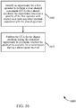
- an opportunity may be identified for a first operator to perform a clear channel assessment (CCA) for a shared spectrum.
- CCA clear channel assessment
- the opportunity may be based on a priority of the first operator with respect to at least one other operator associated with the shared spectrum.
- the CCA may be performed for the shared spectrum during the identified opportunity to determine whether the shared spectrum is available for a transmission during a transmission interval.
- the transmission interval may include a frame or a subframe, wherein the first operator and the at least one other operator are synchronized with respect to a frame timing or a subframe timing, and wherein the first operator and the at least one other operator utilize a same frame structure or subframe structure for the shared spectrum.
- the transmission interval comprises a frame or a subframe, wherein the first operator and the at least one other operator are synchronized with respect to a frame timing or a subframe timing, and wherein the first operator and the at least one other operator utilize two or more different frame structures or subframe structures for the shared spectrum.
- identifying an opportunity for the first operator to perform the CCA for the shared spectrum may include identifying a CCA opportunity for the first operator from a subset of CCA slots in a subframe, the subset of CCA slots based on the priority of the first operator with respect to the at least one other operator.
- the CCA opportunity for the first operator may be earlier in the subframe than a CCA opportunity for the at least one other operator when the priority of the first operator is higher than a priority of the at least one other operator.
- the priority of the first operator with respect to the at least one other operator may include a restriction on the at least one other operator from performing a CCA during the subframe.
- identifying the opportunity for the first operator to perform the CCA for the shared spectrum may include identifying a number of CCA slots for the first operator from among a subset of CCA slots in a subframe, the number of CCA slots based on the priority of the first operator with respect to the at least one other operator.
- the number of CCA slots allotted to the first operator in the subframe may be greater than a number of CCA slots allotted to the at least one other operator in the subframe if the priority of the first operator is higher than a priority of the at least one other operator.
- the number of CCA slots for the first operator in the subframe may be further based on whether a transmission interval for which a CCA is performed is an even numbered transmission interval or an odd numbered transmission interval.
- a frame structure of the first operator restricts the first operator from transmitting over the shared spectrum for at least one transmission interval.
- the frame structure of the first operator may include a silence period that is longer than a silence period for the at least one other operator when the priority of the first operator is lower than a priority of the at least one other operator.
- the opportunity for the first operator to perform the CCA for the shared spectrum may be identified from among two or more CCA slots occupying two or more time periods.
- the opportunity for the first operator to perform the CCA for the shared spectrum may be identified from among two or more CCA slots occupying two or more frequency tones.
- the priority of the first operator with respect to the at least one other operator may be specific to a particular spectrum assigned to a carrier. In cases where one or more operators transmit on multiple carriers, the prioritization may be performed separately or jointly across the two or more carriers.
- the shared spectrum may include an unlicensed spectrum.
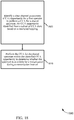
- the opportunity for the first operator to perform the CCA for the shared spectrum may be an opportunity for the first operator to perform a CCA for a first carrier of the shared spectrum.
- a second opportunity may be identified for the first operator to perform a CCA for a second carrier of the shared spectrum, the second opportunity based on the priority of the first operator with respect to the at least one other operator.
- the CCA may be performed for the second carrier of the shared spectrum during the identified second opportunity to determine whether the second carrier of the shared spectrum is available for a transmission during the transmission interval.
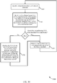
- the opportunity for the first operator to perform the CCA for the shared spectrum may be an opportunity for the first operator to perform a CCA for a first carrier of the shared spectrum, and the priority of the first operator with respect to the at least one other operator associated with the shared spectrum may be a first priority.
- a second opportunity may be identified for the first operator to perform a CCA for a second carrier of the shared spectrum, the second opportunity based on a second priority of the first operator with respect to the at least one other operator associated with the shared spectrum, wherein the second priority is different from the first priority.
- the CCA may be performed for the second carrier of the shared spectrum during the identified second opportunity to determine whether the second carrier of the shared spectrum is available for a transmission during the transmission interval.
- the CCA may be performed by a base station or a user equipment (UE). In certain examples, the CCA may be performed on a downlink and/or an uplink. In certain examples, the priority of the first operator with respect to the at least one other operator may be specific to one of a downlink or an uplink. Alternatively, the priority of the first operator with respect to the at least one other operator may apply to both a downlink and an uplink.
- an apparatus for wireless communications may include means for identifying an opportunity for a first operator to perform a clear channel assessment (CCA) for a shared spectrum, the opportunity based on a priority of the first operator with respect to at least one other operator associated with the shared spectrum, and means for performing the CCA for the shared spectrum during the identified opportunity to determine whether the shared spectrum is available for a transmission during a transmission interval.
- CCA clear channel assessment
- the apparatus for wireless communications may implement one or more of the examples described above with respect to the first set of illustrative embodiments.
- the apparatus for wireless communications may include means for implementing one or more aspects of the method described above with respect to the first set of illustrative embodiments.
- an apparatus for wireless communications may include a processor and memory in electronic communication with the processor.
- the processor may be configured to identify an opportunity for a first operator to perform a clear channel assessment (CCA) for a shared spectrum, the opportunity based on a priority of the first operator with respect to at least one other operator associated with the shared spectrum, and perform the CCA for the shared spectrum during the identified opportunity to determine whether the shared spectrum is available for a transmission during a transmission interval.
- CCA clear channel assessment
- the apparatus for wireless communications may implement one or more of the examples described above with respect to the first or second set of illustrative embodiments.
- the processor may be configured to implement one or more aspects of the method described above with respect to the first set of illustrative embodiments.
- a non-transitory computer-readable medium for storing instructions executable by a processor.
- the computer-readable medium may include instructions to identify an opportunity for a first operator to perform a clear channel assessment (CCA) for a shared spectrum, the opportunity based on a priority of the first operator with respect to at least one other operator associated with the shared spectrum, and instructions to perform the CCA for the shared spectrum during the identified opportunity to determine whether the shared spectrum is available for a transmission during a transmission interval.
- CCA clear channel assessment
- the computer-readable medium may implement one or more of the examples described above with respect to the first, second, or third set of illustrative embodiments.
- the instructions may be executable by the processor to implement one or more aspects of the method described above with respect to the first set of illustrative embodiments.
- each of a plurality of devices may perform a CCA for each of a number of transmission intervals of the shared spectrum, to determine whether the shared spectrum is available for transmissions during the transmission intervals.
- the device may transmit a signal over the shared spectrum to alert other devices that it has reserved the shared spectrum for the transmission interval.
- the devices operated by different operators may perform the CCA in different CCA slots.
- the CCA slot used by the devices of a particular operator may in some cases be pseudo-randomly identified such that the devices of each operator are provided equal access to the shared spectrum. However, it may be useful, in some cases, to prioritize the access provided the devices of different operators.
- the methods, systems, apparatuses, and devices described herein may provide operators of cellular networks (e.g ., operators of Long Term Evolution (LTE) or LTE-Advanced (LTE-A) communications networks) with prioritized access to a shared unlicensed spectrum (e.g ., a WLAN spectrum typically used for WiFi communications).
- LTE Long Term Evolution
- LTE-A LTE-Advanced
- the methods, systems, apparatus, and devices described herein may provide operators of cellular networks with prioritized access to a shared licensed spectrum.
- the techniques disclosed herein may apply to LTE/LTE-A communications transmitted over an unlicensed spectrum.
- a CDMA system may implement a radio technology such as CDMA2000, Universal Terrestrial Radio Access (UTRA), etc.
- CDMA2000 covers IS-2000, IS-95, and IS-856 standards.
- IS-2000 Releases 0 and A are commonly referred to as CDMA2000 IX, IX, etc.
- IS-856 (TIA-856) is commonly referred to as CDMA2000 1xEV-DO, High Rate Packet Data (HRPD), etc.
- UTRA includes Wideband CDMA (WCDMA) and other variants of CDMA.
- a TDMA system may implement a radio technology such as Global System for Mobile Communications (GSM).
- GSM Global System for Mobile Communications
- An OFDMA system may implement a radio technology such as Ultra Mobile Broadband (UMB), Evolved UTRA (E-UTRA), IEEE 802.11 (Wi-Fi), IEEE 802.16 (WiMAX), IEEE 802.20, Flash-OFDM, etc.
- UMB Ultra Mobile Broadband
- E-UTRA Evolved UTRA
- Wi-Fi Wi-Fi
- WiMAX IEEE 802.16
- IEEE 802.20 Flash-OFDM
- UTRA and E-UTRA are part of Universal Mobile Telecommunication System (UMTS).
- LTE and LTE-Advanced (LTE-A) are new releases of UMTS that use E-UTRA.
- UTRA, E-UTRA, UMTS, LTE, LTE-A, and GSM are described in documents from an organization named "3rd Generation Partnership Project" (3GPP).
- CDMA2000 and UMB are described in documents from an organization named "3rd Generation Partnership Project 2" (3GPP2).
- 3GPP2 3rd Generation Partnership Project 2
- the techniques described herein may be used for the systems and radio technologies mentioned above as well as other systems and radio technologies.
- the description below describes an LTE system for purposes of example, and LTE terminology is used in much of the description below, although the techniques are applicable beyond LTE applications.
- the wireless communications system 100 includes a plurality of base stations (e.g ., access points, eNBs, or WLAN access points) 105, a number of user equipments (UEs) 115, and a core network 130. Some of the base stations 105 may communicate with the UEs 115 under the control of a base station controller (not shown), which may be part of the core network 130 or certain base stations 105 ( e.g., access points or eNBs) in various embodiments. Some of the base stations 105 may communicate control information and/or user data with the core network 130 through backhaul 132.
- base stations e.g ., access points, eNBs, or WLAN access points
- Some of the base stations 105 may communicate control information and/or user data with the core network 130 through backhaul 132.
- some of the base stations 105 may communicate, either directly or indirectly, with each other over backhaul links 134, which may be wired or wireless communication links.
- the wireless communications system 100 may support operation on multiple carriers (waveform signals of different frequencies).
- Multi-carrier transmitters can transmit modulated signals simultaneously on the multiple carriers.
- each communications link 125 may be a multi-carrier signal modulated according to various radio technologies.
- Each modulated signal may be sent on a different carrier and may carry control information (e.g ., reference signals, control channels, etc.), overhead information, data, etc.
- the base stations 105 may wirelessly communicate with the UEs 115 via one or more access point antennas. Each of the base stations 105 may provide communication coverage for a respective coverage area 110.
- a base station 105 may be referred to as an access point, a base transceiver station (BTS), a radio base station, a radio transceiver, a basic service set (BSS), an extended service set (ESS), a NodeB, an evolved NodeB (eNB), a Home NodeB, a Home eNodeB, a WLAN access point, a WiFi node or some other suitable terminology.
- BTS base transceiver station
- BSS basic service set
- ESS extended service set
- NodeB an evolved NodeB
- eNB evolved NodeB
- the coverage area 110 for a base station may be divided into sectors making up only a portion of the coverage area (not shown).
- the wireless communications system 100 may include base stations 105 of different types (e.g ., macro, micro, and/or pico base stations).
- the base stations 105 may also utilize different radio technologies, such as cellular and/or WLAN radio access technologies.
- the base stations 105 may be associated with the same or different access networks or operator deployments.
- the coverage areas of different base stations 105, including the coverage areas of the same or different types of base stations 105, utilizing the same or different radio technologies, and/or belonging to the same or different access networks, may overlap.
- the wireless communications system 100 may include an LTE/LTE-A communications system (or network), which LTE/LTE-A communications system may support one or more modes of operation or deployment scenarios for LTE/LTE-A in an unlicensed spectrum.
- the wireless communications system 100 may support wireless communications using an unlicensed spectrum and an access technology different from LTE/LTE-A in an unlicensed spectrum, or a licensed spectrum and an access technology different from LTE/LTE-A.
- the term evolved NodeB or eNB may be generally used to describe of the base stations 105.
- the wireless communications system 100 may be a Heterogeneous LTE/LTE-A or LTE/LTE-A in an unlicensed spectrum network in which different types of eNBs provide coverage for various geographical regions.
- each base station 105 may provide communication coverage for a macro cell, a pico cell, a femto cell, and/or other types of cell.
- Small cells such as pico cells, femto cells, and/or other types of cells may include low power nodes or LPNs.
- a macro cell generally covers a relatively large geographic area ( e.g., several kilometers in radius) and may allow unrestricted access by UEs with service subscriptions with the network provider.
- a pico cell would generally cover a relatively smaller geographic area and may allow unrestricted access by UEs with service subscriptions with the network provider.
- a femto cell would also generally cover a relatively small geographic area (e.g., a home) and, in addition to unrestricted access, may also provide restricted access by UEs having an association with the femto cell (e.g., UEs in a closed subscriber group (CSG), UEs for users in the home, and the like).
- An eNB for a macro cell may be referred to as a macro eNB.
- An eNB for a pico cell may be referred to as a pico eNB.
- an eNB for a femto cell may be referred to as a femto eNB or a home eNB.
- An eNB may support one or multiple ( e.g ., two, three, four, and the like) cells.
- the core network 130 may communicate with the base stations 105 via a backhaul 132 (e.g., S1, etc.).
- the base stations 105 may also communicate with one another, e.g., directly or indirectly via backhaul links 134 ( e.g., X2, etc.) and/or via backhaul 132 ( e.g., through core network 130).
- the wireless communications system 100 may support synchronous or asynchronous operation.
- the base stations may have similar frame and/or gating timing, and transmissions from different base stations may be approximately aligned in time.
- For asynchronous operation the base stations may have different frame and/or gating timing, and transmissions from different base stations may not be aligned in time.
- the techniques described herein may be used for either synchronous or asynchronous operations.
- the UEs 115 may be dispersed throughout the wireless communications system 100, and each UE 115 may be stationary or mobile.
- a UE 115 may also be referred to by those skilled in the art as a mobile device, a mobile station, a subscriber station, a mobile unit, a subscriber unit, a wireless unit, a remote unit, a wireless device, a wireless communication device, a remote device, a mobile subscriber station, an access terminal, a mobile terminal, a wireless terminal, a remote terminal, a handset, a user agent, a mobile client, a client, or some other suitable terminology.
- a UE 115 may be a cellular phone, a personal digital assistant (PDA), a wireless modem, a wireless communication device, a handheld device, a tablet computer, a laptop computer, a cordless phone, a wearable item such as a watch or glasses, a wireless local loop (WLL) station, or the like.
- PDA personal digital assistant
- a UE 115 may be able to communicate with macro eNBs, pico eNBs, femto eNBs, relays, and the like.
- a UE 115 may also be able to communicate over different access networks, such as cellular or other WWAN access networks, or WLAN access networks.
- the communications links 125 shown in wireless communications system 100 may include uplinks for carrying uplink (UL) transmissions (e.g ., from a UE 115 to a base station 105) and/or downlinks for carrying downlink (DL) transmissions (e.g ., from a base station 105 to a UE 115).
- the UL transmissions may also be called reverse link transmissions, while the DL transmissions may also be called forward link transmissions.
- the downlink transmissions may be made using a licensed spectrum, an unlicensed spectrum, or both.
- the uplink transmissions may be made using a licensed spectrum, an unlicensed spectrum, or both.
- various deployment scenarios for LTE/LTE-A in an unlicensed spectrum may be supported, including a supplemental downlink mode in which LTE downlink capacity in a licensed spectrum may be offloaded to an unlicensed spectrum, a carrier aggregation mode in which both LTE downlink and uplink capacity may be offloaded from a licensed spectrum to an unlicensed spectrum, and a standalone mode in which LTE downlink and uplink communications between a base station (e.g ., an eNB) and a UE may take place in an unlicensed spectrum.
- Base stations 105 as well as UEs 115 may support one or more of these or similar modes of operation.
- OFDMA communications signals may be used in the communications links 125 for LTE downlink transmissions in an unlicensed and/or a licensed spectrum, while SC-FDMA communications signals may be used in the communications links 125 for LTE uplink transmissions in an unlicensed and/or a licensed spectrum.
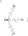
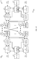
- a wireless communications system 200 illustrates examples of a supplemental downlink mode and a carrier aggregation mode for an LTE network that supports LTE/LTE-A in an unlicensed spectrum.
- the wireless communications system 200 may be an example of portions of the wireless communications system 100 of FIG. 1 .
- the base station 205 may be an example of the base stations 105 of FIG. 1
- the UEs 215, 215-a, and 215-b may be examples of the UEs 115 of FIG. 1 .
- the base station 205 may transmit OFDMA communications signals to a UE 215 using a downlink 220.
- the downlink 220 may be associated with a frequency F1 in an unlicensed spectrum.
- the base station 205 may transmit OFDMA communications signals to the same UE 215 using a bidirectional link 225 and may receive SC-FDMA communications signals from that UE 215 using the bidirectional link 225.
- the bidirectional link 225 may be associated with a frequency F4 in a licensed spectrum.
- the downlink 220 in the unlicensed spectrum and the bidirectional link 225 in the licensed spectrum may operate concurrently.
- the downlink 220 may provide a downlink capacity offload for the base station 205.
- the downlink 220 may be used for unicast services (e.g ., addressed to one UE) services or for multicast services (e.g ., addressed to several UEs).
- This scenario may occur with any service provider (e.g ., traditional mobile network operator or MNO) that uses a licensed spectrum and needs to relieve some of the traffic and/or signaling congestion.
- MNO mobile network operator
- the base station 205 may transmit OFDMA communications signals to a UE 215-a using a bidirectional link 230 and may receive SC-FDMA communications signals from the same UE 215-a using the bidirectional link 230.
- the bidirectional link 230 may be associated with the frequency F1 in the unlicensed spectrum.
- the base station 205 may also transmit OFDMA communications signals to the same UE 215-a using a bidirectional link 235 and may receive SC-FDMA communications signals from the same UE 215-a using the bidirectional link 235.
- the bidirectional link 235 may be associated with a frequency F2 in a licensed spectrum.
- the bidirectional link 230 may provide a downlink and uplink capacity offload for the base station 205. Like the supplemental downlink described above, this scenario may occur with any service provider (e.g ., MNO) that uses a licensed spectrum and needs to relieve some of the traffic and/or signaling congestion.
- MNO service provider
- the base station 205 may transmit OFDMA communications signals to a UE 215-b using a bidirectional link 240 and may receive SC-FDMA communications signals from the same UE 215-b using the bidirectional link 240.
- the bidirectional link 240 may be associated with a frequency F3 in an unlicensed spectrum.
- the base station 205 may also transmit OFDMA communications signals to the same UE 215-b using a bidirectional link 245 and may receive SC-FDMA communications signals from the same UE 215-b using the bidirectional link 245.
- the bidirectional link 245 may be associated with the frequency F2 in the licensed spectrum.
- the bidirectional link 240 may provide a downlink and uplink capacity offload for the base station 205.
- This example and those provided above are presented for illustrative purposes and there may be other similar modes of operation or deployment scenarios that combine LTE in a licensed spectrum and LTE in an unlicensed spectrum for capacity offload.
- an operational configuration may include a bootstrapped mode (e.g. , supplemental downlink, carrier aggregation) that uses an LTE primary component carrier (PCC) on a licensed spectrum and a secondary component carrier (SCC) on an unlicensed spectrum.
- PCC primary component carrier
- SCC secondary component carrier
- data and control may generally be communicated in a licensed spectrum (e.g ., bidirectional links 225, 235, and 245) while data may generally be communicated in an unlicensed spectrum (e.g. , bidirectional links 230 and 240).
- the carrier aggregation mechanisms supported when using the unlicensed spectrum may fall under a hybrid frequency division duplexing-time division duplexing (FDD-TDD) carrier aggregation or a TDD-TDD carrier aggregation with different symmetry across component carriers.
- FDD-TDD hybrid frequency division duplexing-time division duplexing
- FIG. 2B shows a wireless communications system 250 that illustrates an example of a standalone mode for LTE in an unlicensed spectrum.
- the wireless communications system 250 may be an example of portions of the wireless communications system 100 of FIG. 1 .
- the base station 205 may be an example of the base stations 105 and/or 205 described with reference to FIGs. 1 and/or 2A, while the UE 215-c may be an example of the UEs 115 and/or 215 of FIGs. 1 and/or 2A.
- the base station 205 may transmit OFDMA communications signals to the UE 215-c using a bidirectional link 255 and may receive SC-FDMA communications signals from the UE 215-c using the bidirectional link 255.
- the bidirectional link 255 may be associated with the frequency F3 in an unlicensed spectrum described above with reference to FIG. 2A .
- the standalone mode may be used in non-traditional wireless access scenarios, such as in-stadium access ( e.g ., unicast, multicast).
- the typical service provider for this mode of operation may be a stadium owner, cable company, event host, hotel, enterprise, or large corporation that does not have a licensed spectrum.
- a transmitting device such as a base station 105 and/or 205 described with reference to FIGs. 1 , 2A , and/or 2B, or a UE 115 and/or 215 described with reference to FIGs. 1 , 2A , and/or 2B, may use a gating interval to gain access to a channel of the shared spectrum (e.g ., to a channel of the licensed or unlicensed spectrum).
- the gating interval may define an application of a contention-based protocol, such as a Listen Before Talk (LBT) protocol based on the LBT protocol specified in ETSI (EN 301 893).
- LBT Listen Before Talk
- the gating interval may indicate when a transmitting device needs to perform a Clear Channel Assessment (CCA).
- CCA Clear Channel Assessment
- the outcome of the CCA indicates to the transmitting device whether a channel of the shared spectrum is available or in use.
- the gating interval may allow the transmitting device to use the channel - typically for a predefined transmission interval.
- the gating interval may prevent the transmitting device from using the channel during the transmission interval.
- a transmitting device may be useful for a transmitting device to generate a gating interval on a periodic basis and synchronize at least one boundary of the gating interval with at least one boundary of a periodic frame structure.
- FIG. 3 illustrates examples 300 of an unlicensed frame/interval 305, 315, and/or 325 for a cellular downlink in an unlicensed spectrum.
- the unlicensed frame/interval 305, 315, and/or 325 may be used as a periodic gating interval by a base station that supports transmissions over the unlicensed spectrum. Examples of such a base station may be the base stations 105 and/or 205 described with reference to FIGs. 1 , 2A , and/or 2B.
- the unlicensed frame/interval 305, 315, and/or 325 may be used with the wireless communications system 100, 200, and/or 250 described with reference to FIGs. 1 , 2A , and/or 2B.
- the duration of the unlicensed frame/interval 305 is shown to be equal to (or approximately equal to) a duration of an LTE/LTE-A radio frame 310 of a periodic frame structure associated with a cellular downlink.
- “approximately equal” means the duration of the unlicensed frame/interval 305 is within a cyclic prefix (CP) duration of the duration of the periodic frame structure.
- CP cyclic prefix
- At least one boundary of the unlicensed frame/interval 305 may be synchronized with at least one boundary of the periodic frame structure that includes the LTE/LTE-A radio frames N-1 to N+1.
- the unlicensed frame/interval 305 may have boundaries that are aligned with the frame boundaries of the periodic frame structure.
- the unlicensed frame/interval 305 may have boundaries that are synchronized with, but offset from, the frame boundaries of the periodic frame structure.
- the boundaries of the unlicensed frame/interval 305 may be aligned with sub frame boundaries of the periodic frame structure, or with subframe midpoint boundaries ( e.g ., the midpoints of particular subframes) of the periodic frame structure.
- the periodic frame structure may include LTE/LTE-A radio frames N-1 to N+1.
- Each LTE/LTE-A radio frame 310 may have a duration of ten milliseconds, for example, and the unlicensed frame/interval 305 may also have a duration of ten milliseconds.
- the boundaries of the unlicensed frame/interval 305 may be synchronized with the boundaries (e.g ., frame boundaries, subframe boundaries, or subframe midpoint boundaries) of one of the LTE/LTE-A radio frames (e.g., the LTE/LTE-A radio frame (N)).
- the duration of the unlicensed frames/intervals 315 and 325 are shown to be sub-multiples of (or approximate sub-multiples of) the duration of the periodic frame structure associated with the cellular downlink.
- an "approximate sub-multiple of' means the duration of the unlicensed frame/interval 315, 325 is within a cyclic prefix (CP) duration of the duration of a sub-multiple of ( e.g., half or one-tenth) the periodic frame structure.
- CP cyclic prefix
- the unlicensed frame/interval 315 may have a duration of five milliseconds and the unlicensed frame/interval 325 may have a duration of 1 or 2 milliseconds.
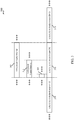
- FIG. 4 illustrates an example 400 of a periodic gating interval 405 for a cellular downlink in an unlicensed spectrum.
- the periodic gating interval 405 may be used by a base station that supports LTE/LTE-A in an unlicensed spectrum. Examples of such a base station may be the base stations 105 and 205 described with reference to FIGs. 1 , 2A , and/or 2B.
- the periodic gating interval 405 may also be used with the wireless communications system 100, 200, and/or 250 of FIGs. 1 , 2A , and and/or 2B.
- the duration of the periodic gating interval 405 is shown to be equal to (or approximately equal to) the duration of a periodic frame structure 410 associated with the cellular downlink.
- the boundaries of the periodic gating interval 405 may be synchronized with ( e.g ., aligned with) the boundaries of the periodic frame structure 410.
- the periodic frame structure 410 may include an LTE/LTE-A radio frame having ten subframes (e.g ., SF0, SF1, ..., SF9).
- Subframes SF0 through SF8 may be downlink (D) subframes 415
- subframe SF9 may be a special (S') subframe 420.
- the D subframes 415 may collectively define a channel occupancy time of the LTE radio frame, and at least part of the S' subframe 420 may define a channel idle time.
- an LTE/LTE-A radio frame may have a maximum channel occupancy time (ON time) between one and 9.5 milliseconds, and a minimum channel idle time (OFF time) of five percent of the channel occupancy time (e.g ., a minimum of 50 microseconds).
- the periodic gating interval 405 may abide by these requirements of the LTE/LTE-A standard by providing a 0.5 millisecond guard period ( i.e., OFF time) as part of the S' subframe 420.
- the S' subframe 420 may include one or more CCA slots or windows 425 in which the transmitting devices contending for a particular channel of an unlicensed spectrum may perform their CCAs.
- the device's CCA indicates the channel is available, but the device's CCA is completed before the end of the periodic gating interval 405, the device may transmit one or more signals to reserve the channel until the end of the periodic gating interval 405.
- the one or more signals may in some cases include Channel Usage Beacon Signals (CUBS) or Partial CUBS (PCUBS), also referred to as Channel Usage Pilot Signals (CUPS) 430, respectfully.
- CUBS Channel Usage Beacon Signals
- PCUBS Partial CUBS
- CUPS Channel Usage Pilot Signals
- CUBS (or CUPS) 430 may be used for both channel synchronization and channel reservation. That is, a device that performs a CCA for the channel after another device begins to transmit CUBS on the channel may detect the energy of the CUBS 430 and determine that the channel is currently unavailable.
- the transmitting device may use the channel for up to a predetermined period of time (e.g., one LTE radio frame) to transmit a waveform (e.g ., an LTE-based waveform 435).
- a predetermined period of time e.g., one LTE radio frame
- a waveform e.g ., an LTE-based waveform 435
- FIG. 5 illustrates a wireless communications system 500 in which a number of wireless access points (e.g. , WiFi nodes) 535 and a UE 515 are within the coverage area 510 of a base station 505.
- the base station 505, UE 515, and/or wireless access points 535 may be respective examples of one or more aspects of the base stations 105 and/or 205, UEs 115 and/or 215, and/or wireless access points 105 described with reference to FIGs. 1 , 2A , and/or 2B.
- the base station 505 and UE 515 may communicate with one another over a licensed or unlicensed spectrum using either or both of a bidirectional link 520 in an licensed spectrum and a bidirectional link 525 in an unlicensed spectrum. Such communication may be an example of the carrier aggregation scenario described above with respect to FIG. 2A .
- both the base station 505 and the UE 515 may perform CCAs to determine availability of the unlicensed spectrum. In some cases, both the base station 505 and the UE 515 may perform CCAs to account for the presence of wireless access points 540 and/or other potential transmitting devices that are outside the coverage area 510 of the base station 505, but within range of the UE 515. Such wireless access points 540 may be referred to as "hidden nodes,” because their presence may be unknown to and hidden from the base station 505.
- the base station 505 might determine that the unlicensed spectrum is available in a particular transmission interval when, in fact, a hidden wireless access point 540 has already reserved the unlicensed spectrum in the vicinity of the UE 515).
- FIG. 6 illustrates how a contention-based protocol such as LBT may be implemented within an S' subframe 600 of a gating interval, such as an S' subframe of the ten millisecond periodic gating interval 405 described with reference to FIG. 4 .
- the contention-based protocol may be used with, for example, the wireless communications system 100, 200, 250, and/or 500, base stations 105, 205, and/or 505, and/or UEs 115, 215, and/or 515 described with reference to FIGs. 1 , 2A , 2B , and/or 5.
- the S' subframe 600 may have a guard period (or silence period) 605 and a CCA period 610.
- each of the guard period 605 and the CCA period 610 may have a duration of 0.5 milliseconds and include seven OFDM symbol positions 615 (labeled in FIG. 6 as Slot 1 through 7).
- a base station may select one or more of the OFDM symbol positions 615 to perform a CCA 620 for a subsequent transmission interval of an unlicensed spectrum, to determine whether the transmission interval of the unlicensed spectrum is available for a transmission during the transmission interval.
- different ones of the OFDM symbol positions 615 may be pseudo-randomly identified or selected by a base station in different occurrences of the S' subframe 600 ( i.e., in different S' subframes used to perform a CCA 620 for different transmission intervals of the unlicensed spectrum).
- the pseudo-random identification or selection of OFDM symbol positions may be controlled using a hopping sequence.
- the LBT protocol may take the form of an LBT Frame Based Equipment (LBT-FBE) protocol or an LBT Load Based Equipment (LBT-LBE) protocol.
- LBT-FBE LBT Frame Based Equipment
- LBT-LBE LBT Load Based Equipment
- An LBT-FBE protocol may have a fixed/periodic timing and may not be directly influenced by traffic demand (e.g ., its timing can be changed through reconfiguration).
- traffic demand e.g ., its timing can be changed through reconfiguration
- an LBT-LBE protocol may not have a fixed timing ( i.e., be asynchronous) and may be largely influenced by traffic demand.
- the base stations of a wireless communications system may be operated by the same or different operators.
- the base stations operated by different operators may select different ones of the OFDM symbol positions 615 in a particular S' subframe 600, thereby avoiding CCA collisions between different operators.
- OFDM symbol positions 615 may be pseudo-randomly selected by a plurality of different operators such that the base stations of the different operators each have an equal opportunity to perform a CCA 620 in the earliest OFDM symbol position (i.e., Slot 1) for certain transmission intervals.
- the base stations of the different operators may each have an opportunity to perform a CCA 620 first and gain access to a transmission interval of the unlicensed spectrum regardless of the needs of other base stations of other operators.
- a base station may transmit CUBS to prevent other operators from using one or more channels of the transmission interval of the unlicensed spectrum.
- a shared spectrum e.g ., a shared licensed spectrum and/or a shared unlicensed spectrum.
- a need for prioritization may arise for various reasons. For example, different operators may pay different rates for accessing a shared spectrum, depending on the quality of service each operator desires. Or, for example, one operator may rent a percentage of their shared spectrum access rights to another operator, and may desire a mechanism to enforce the use percentage.
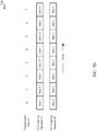
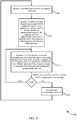
- FIGS. 7A , 7B , 7C , and 7D illustrate various techniques for prioritizing access to a shared spectrum.
- Each of these figures illustrates a sequence of transmission intervals and, assuming use of a gating interval including the S' subframe 600 described with reference to FIG. 6 , shows which OFDM symbol position or CCA slot is used by a first operator (Operator #1) and a second operator (Operator #2) in each of the transmission intervals.
- FIG. 7A there is shown an example of a fixed prioritization technique 700, in which the first operator uses Slot 1 to perform a CCA in each transmission interval and the second operator uses Slot 2 to perform a CCA in each transmission interval.
- the first operator is able to access the shared spectrum in any transmission interval that it desires to access the shared spectrum (assuming no interference from hidden nodes).
- a set of CCA opportunities identified by each of the first and second operators may be restricted on a per operator basis.
- the first operator (Operator #1) may have a CCA hopping within Slot 1, Slot 2, and Slot 7, and the second operator (Operator #2) may identify the CCA locations within Slot 3, Slot 4, Slot 5, and Slot 6.
- the first operator may have a two in three (2/3) chance of gaining access to a transmission interval of the shared spectrum over the second operator.
- FIG. 7C there is shown an example of a restricted transmission prioritization technique 720, in which the first operator performs CCA for each of the transmission intervals, but the second operator is restricted from performing CCA and/or transmitting in every other transmission intervals (e.g ., in odd numbered transmission intervals).
- the second operator may perform CCA for each of the transmission intervals, but with a hopping sequence that is opposite that used by the first operator.
- the CCA performed by the second operator may be declared invalid, thereby restricting the second operator from transmitting in the odd numbered transmission intervals. In the illustrated example, this provides the first operator a three in four chance of gaining access to a transmission interval of the shared spectrum.
- each of operators may be allocated two or more CCA locations in at least some transmission intervals.
- the first operator is allocated two CCA slots for odd numbered transmission intervals and one CCA slot for even numbered transmission intervals, as shown in FIG. 7D .
- the second operator is allocated only one CCA slot in each transmission interval.
- the first and/or second operator may be allocated two or more CCA slots in any number of transmission intervals, with static or varying assignments of slot numbers.
- the first operator has an approximate three in two chance of gaining access to a transmission interval of the shared spectrum.
- each of the prioritization techniques described with reference to FIGS. 7A-7D may be extended to prioritize more than two operators.
- the priority of the first operator with respect to at least one other operator may be specific to a particular spectrum assigned to a carrier. That is, the first operator may be the only operator having a priority with respect to the at least one other operator for the particular spectrum.
- the priority of the first operator with respect to the at least one other operator may be shared by other operators. That is, the first operator may have the same priority as another operator (e.g., a second operator) with respect to the at least one other operator. The latter may be achieved using orthogonal transmissions and/or other techniques for sharing a same spectrum.
- First and second operators may also share the same priority with respect to the at least one other operator by, for example, alternating the priority given the first and second operators in alternating transmission intervals, such that, over time, each of the first and second operators is provided the same priority with respect to the same spectrum.
- the prioritization may be performed separately or jointly across the two or more carriers.
- the CCA opportunity for each operator may change over different transmission intervals, and over a long run, the hopping of CCA opportunities may be such that each operator has an equal share of occupancy rate.
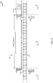
- FIG. 8A provides an example 800 of a one millisecond (e.g ., one LTE/LTE-A subframe) gating interval 805.
- a one millisecond gating interval 805 may be used by the base stations 105, 205, and/or 505 described with reference to FIGs. 1 , 2A , 2B , and/or 5.
- the gating interval 805 may be used with the wireless communications system 100, 200, 250, and/or 500 of FIGs. 1 , 2A , 2B , and/or 5.
- Versions of the LTE specification require a channel occupancy time (ON time) ⁇ one millisecond. Under a channel idle time ⁇ five percent of the channel occupancy time, the LTE specification may dictate a minimum gating interval duration of 1.05 milliseconds. However, if the LTE specification could be relaxed to require a minimum channel occupancy time of perhaps 0.95 milliseconds, then a one millisecond gating interval would be possible.
- a gating interval 805 of one millisecond may include 14 OFDM symbols (or symbol positions).
- a successful CCA is performed during a CCA slot 810 preceding the gating interval 805
- a downlink transmission may occur during the first 13 OFDM symbols of the gating interval 805.
- Such a downlink transmission may have a duration (or channel occupancy time) of 929 microseconds.
- a channel occupancy time of 929 microseconds would require a channel idle time 815 of 48 microseconds, which is less than the 71.4 microsecond duration of one OFDM symbol.
- the channel idle time 815 of 48 microseconds, as well as one or more CCA slots 810, may be provided during the 14 th OFDM symbol position.
- two CCA slots 810 having a total duration of 20 microseconds may be provided during the 14 th OFDM symbol position, thereby enabling some amount of CCA randomization.
- each CCA slot 810 in the example 800 has a duration of less than one OFDM symbol.
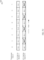
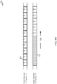
- FIG. 8B there is shown an example comparison 820 of a first frame structure for a first operator (Operator #1) and a second frame structure for a second operator (Operator #2).
- Each frame structure includes ten subframes (i.e., subframes SF0 through SF9).
- Each subframe of the frame structure of the first operator may be configured as described with reference to FIG. 8A and may include an approximate five percent silence period 825, thereby enabling a CCA slot to be identified, and a CCA is performed, in each subframe of the frame structure of the first operator.
- the frame structure of the first operator may follow a ten-subframe based structure, where a CCA is performed in one of the ten subframes instead of in every single subframe, while the remaining subframes may be fully utilized (except for possible switching from downlink to uplink transmissions or vice versa).
- the frame structure of the second operator has an approximate fifty percent silence period 830, which silence period restricts the second operator from performing a CCA and/or transmitting in each of subframes SF0 through SF4.
- Such a difference in silence periods provides the first operator with opportunities to access at least five transmission intervals of a shared spectrum without competing with the second operator for access to the five transmission intervals.
- the priority of the first operator over the second operator may be further extended by, for example, increasing the length of the silence period for the frame structure of the second operator and/or applying one of the prioritization techniques described with reference to FIGs. 7A , 7B , 7C , and/or 7D to subframes SF5 through SF9.
- a device e.g., a base station of a first operator may be capable of transmitting over two or more carriers (e.g ., two or more frequency tones).
- a CCA may be performed for the different carriers using an example 900 of a single prioritization technique for all carriers, as shown in FIG. 9A .
- different prioritization techniques may be applied to some or all of the carriers. Different prioritization techniques may in some cases be selected from among the various techniques described with reference to FIGs. 7A , 7B , 7C , 7D , and/or 8B, or variants thereof.
- the different prioritization techniques may provide a first operator with priority over at least one other operator with respect to a first set of one or more carriers, while providing the at least one other operator priority over the first operator with respect to a second set of one or more carriers.
- different opportunities for an operator to perform a CCA for a shared spectrum may be identified from among two or more CCA slots occupying two or more time periods, as shown for example in FIGs. 6 , 7A , 7B , 7C , and/or 7D.
- different opportunities for an operator to perform a CCA for the shared spectrum may be identified from among two or more CCA slots occupying two or more frequency tones associated with different priorities.
- different opportunities for an operator to perform a CCA for the shared spectrum may be identified from among two or more CCA slots occupying a combination of both different time periods and different frequency tones.
- the described techniques are applicable to a eNB, a user equipment or both.
- a same or different technique may be applied for a downlink CCA and an uplink CCA.
- a same or different prioritization criterion may be applied for a downlink CCA and an uplink CCA. That is, a same or different prioritization may be applied in downlink and uplink operations across operators. The prioritization among operators may further depend on the downlink/uplink frame structure used by each operator.
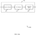
- a block diagram 1000 illustrates a device 1005 for use in wireless communications in accordance with various embodiments.
- the device 1005 may be an example of one or more aspects of the base stations 105, 205, and/or 505 described with reference to FIGs. 1 , 2A , 2B , and/or 5.
- the device 1005 may also be a processor.
- the device 1005 may include a receiver module 1010, a CCA module 1015, and/or a transmitter module 1020. Each of these components may be in communication with each other.
- the components of the device 1005 may, individually or collectively, be implemented with one or more application-specific integrated circuits (ASICs) adapted to perform some or all of the applicable functions in hardware.
- ASICs application-specific integrated circuits
- the functions may be performed by one or more other processing units (or cores), on one or more integrated circuits.
- other types of integrated circuits e.g., Structured/Platform ASICs, Field Programmable Gate Arrays (FPGAs), and other Semi-Custom ICs), which may be programmed in any manner known in the art.
- the functions of each unit may also be implemented, in whole or in part, with instructions embodied in a memory, formatted to be executed by one or more general or application-specific processors.
- the receiver module 1010 may be or include a radio frequency (RF) receiver, such as an RF receiver operable to receive transmissions in a licensed spectrum and/or an unlicensed spectrum.
- the receiver module 1010 may be used to receive various types of data and/or control signals (i.e., transmissions) over one or more communication links of a wireless communications system including the licensed and/or unlicensed spectrums, such as one or more communication links of the wireless communications system 100, 200, 250, and/or 500 described with reference to FIGs. 1 , 2A , 2B , and/or 5.
- RF radio frequency
- the transmitter module 1020 may be or include an RF transmitter, such as an RF transmitter operable to transmit in the licensed spectrum and/or the unlicensed spectrum.
- the transmitter module 1020 may be used to transmit various types of data and/or control signals (i.e., transmissions) over one or more communication links of a wireless communications system, such as one or more communication links of the wireless communications system 100, 200, 250, and/or 500 described with reference to FIGs. 1 , 2A , 2B , and/or 5.
- the CCA module 1015 may be used to perform a CCA for a shared spectrum.
- the CCA may in some cases be performed using the gating interval described with reference to FIGs. 4 and/or 8A.
- the CCA may be performed within a CCA slot for a particular transmission interval, with the identity of the CCA slot being based on a priority of an operator (e.g., a network operator or service provider) that operates the base station or device 1005.
- the priority of the operator may in some cases be a priority of the operator with respect to at least one other operator.
- the identity of the CCA slot for a particular transmission interval may be determined using one of the techniques described with reference to FIGs. 7A , 7B , 7C , 7D , and/or 8B.
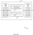
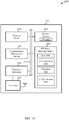
- a block diagram 1050 illustrates a device 1055 for use in wireless communications in accordance with various embodiments.
- the device 1055 may be an example of one or more aspects of the base stations or devices 105, 205, 505, and/or 1005 described with reference to FIGs. 1 , 2A , 2B , 5 , and/or 10A.
- the device 1055 may also be a processor.
- the device 1055 may include a receiver module 1060, a CCA module 1065, and/or a transmitter module 1070. Each of these components may be in communication with each other.
- the components of the device 1055 may, individually or collectively, be implemented with one or more ASICs adapted to perform some or all of the applicable functions in hardware. Alternatively, the functions may be performed by one or more other processing units (or cores), on one or more integrated circuits. In other embodiments, other types of integrated circuits may be used (e.g ., Structured/Platform ASICs, FPGAs, and other Semi-Custom ICs), which may be programmed in any manner known in the art. The functions of each unit may also be implemented, in whole or in part, with instructions embodied in a memory, formatted to be executed by one or more general or application-specific processors.
- the receiver module 1060 may be or include an RF receiver, such as an RF receiver operable to receive transmissions in a licensed spectrum and/or an unlicensed spectrum.
- the RF receiver may include separate receivers for the licensed spectrum and the unlicensed spectrum.
- the separate receivers may in some cases take the form of a licensed spectrum module 1062 and an unlicensed spectrum module 1064.
- the receiver module 1060 including the licensed spectrum module 1062 and/or the unlicensed spectrum module 1064, may be used to receive various types of data and/or control signals ( i.e., transmissions) over one or more communication links of a wireless communications system including the licensed and unlicensed spectrums, such as one or more communication links of the wireless communications system 100, 200, 250, and/or 500 described with reference to FIGs. 1 , 2A , 2B , and/or 5.
- the transmitter module 1070 may be or include an RF transmitter, such as an RF transmitter operable to transmit in the licensed spectrum and/or the unlicensed spectrum.
- the RF transmitter may include separate transmitters for the licensed spectrum and the unlicensed spectrum.
- the separate transmitters may in some cases take the form of a licensed spectrum module 1072 and an unlicensed spectrum module 1074.
- the transmitter module 1070, including the licensed spectrum module 1072 and/or the unlicensed spectrum module 1074, may be used to transmit various types of data and/or control signals ( i.e., transmissions) over one or more communication links of a wireless communications system, such as one or more communication links of the wireless communications system 100, 200, 250, and/or 500 described with reference to FIGs. 1 , 2A , 2B , and/or 5.
- the CCA module 1065 may be an example of one or more aspects of the CCA module 1015 described with reference to FIG. 10A and may include a CCA opportunity identification module 1075 and/or a CCA performance module 1080.
- the CCA opportunity identification module 1075 may be used to identify an opportunity for an operator of the device 1055 to perform a CCA for a shared spectrum.
- the shared spectrum may include a licensed and/or unlicensed spectrum.
- the identified opportunity may be based on a priority of the operator of the device 1055 with respect to at least one other operator associated with the shared spectrum.
- the CCA performance module 1080 may be used to perform a CCA for the shared spectrum during the identified opportunity to determine whether the shared spectrum is available for a transmission during a transmission interval.
- the transmission interval may include a frame or a subframe
- the operator of the device 1055 and the at least one other operator may be synchronized with respect to a frame timing or a subframe timing.
- the operator of the device 1055 and the at least one other operator may utilize a same frame structure or subframe structure for the shared spectrum.
- the operator of the device 1055 and the at least one other operator may utilize two or more different frame structures or subframe structures for the shared spectrum.
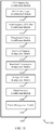
- a block diagram 1100 illustrates one embodiment of a CCA opportunity identification module 1105, in accordance with various embodiments.
- the CCA opportunity identification module 1105 may be an example of one or more aspects of the CCA opportunity identification module 1075 described with reference to FIG. 10B .
- the CCA opportunity identification module 1105 may include a CCA priority type determination module 1110, a time/frequency CCA slot identification module 1115, a transmission interval identification module 1120, a restricted hopping management module 1125, a restricted transmission management module 1130, a multiple CCA slot management module 1135, a frame structure identification module 1140, and/or a carrier management module 1145.
- the components of the CCA opportunity identification module 1105 may, individually or collectively, be implemented with one or more ASICs adapted to perform some or all of the applicable functions in hardware. Alternatively, the functions may be performed by one or more other processing units (or cores), on one or more integrated circuits. In other embodiments, other types of integrated circuits may be used (e.g., Structured/Platform ASICs, FPGAs, and other Semi-Custom ICs), which may be programmed in any manner known in the art. The functions of each unit may also be implemented, in whole or in part, with instructions embodied in a memory, formatted to be executed by one or more general or application-specific processors.
- the CCA priority type determination module 1110 may be used to determine which of a number of CCA priority types defines a priority of a first operator (e.g., an operator of a device in which the CCA opportunity identification module 1105 is provided) with respect to at least one other operator.
- the number of priority types may include, for example, any or all of the priority types described with reference to FIGs. 7A , 7B , 7C , 7D , and/or 8B.
- the time/frequency CCA slot identification module 1115 may be used to identify a set or subset of CCA slots (i.e., opportunities) in which the first operator may perform a CCA for the shared spectrum. In some embodiments, the time/frequency CCA slot identification module 1115 may identify the set or subset of CCA slots from among two or more CCA slots occupying two or more time periods. In other embodiments, the time/frequency CCA slot identification module 1115 may identify the set or subset of CCA slots from among two or more CCA slots occupying two or more frequency tones associated with different priorities. In further embodiments, the time/frequency CCA slot identification module 1115 may identify the set or subset of CCA slots from among two or more CCA slots occupying a combination of both different time periods and different frequency tones.
- the transmission interval identification module 1120 may be used to identify a transmission interval for which a CCA is to be performed.
- the transmission interval may be a transmission interval of a shared spectrum.
- the shared spectrum may include a licensed and/or unlicensed spectrum.
- the transmission interval may be identified by a frame number, or as a transmission interval associated with an even or an odd frame number.
- the restricted hopping management module 1125 may be used to identify a CCA opportunity when the priority of a first operator with respect to at least one other operator includes a restricted hopping type of CCA priority.
- the CCA opportunity may be identified from a subset of CCA slots in a subframe, based on a priority of the first operator with respect to the at least one other operator associated.
- the subset of CCA slots identified by the restricted hopping management module 1125 may ensure that the first operator has a CCA priority in more transmission intervals than the at least one other operator.
- FIG. 7B illustrates an example in which a first operator has a CCA priority over a second operator in two out of every three transmission intervals.
- the subset of CCA slots identified by the restricted hopping management module 1125 may provide the first operator with a CCA priority in fewer transmission intervals than the at least one other operator.
- the restricted transmission management module 1130 may be used to determine whether the priority of the first operator with respect to at least one other operator restricts the first operator from performing a CCA in an identified CCA slot. For example, the restricted transmission management module 1130 may determine, based on the priority of the first operator with respect to the at least one other operator, whether a CCA slot identified for the first operator to perform a CCA for an identified transmission interval is invalid for performing the CCA by the first operator.
- FIG. 7C illustrates an example in which a first operator has no restrictions on performing a CCA, while a second operator is restricted from performing a CCA in every other transmission interval ( e.g ., every other frame).
- the hopping sequence may include all or a subset of the CCA slots in a subframe.
- the same hopping sequence may be used for operators having different priorities over other operators, because the priority of one operator over another operator in a shared spectrum may be controlled by restricting one or more operators from performing a CCA for a particular transmission interval of the shared spectrum.
- the multiple CCA slot management module 1135 may be used to identify a number of CCA opportunities for a first operator to perform a CCA for an identified transmission interval of a shared spectrum.
- the number of CCA opportunities identified for the first operator may vary depending on the identity of the transmission interval.
- the multiple CCA slot management module 1135 may allot a first operator one CCA slot during even numbered transmission intervals and two CCA slots during odd numbered transmission intervals.
- the priority of the first operator is higher than a priority of at least one other operator, the number of CCA opportunities associated with the priority of the first operator, over time, may ensure that the first operator is allotted more CCA slots than the at least one other operator. For example, FIG.
- 7D illustrates an example in which a first operator is allotted three CCA slots for every two CCA slots allotted to a second operator.
- the priority of the first operator is lower than the priority of the at least one other operator, the number of CCA opportunities associated with the priority of the first operator, over time, may provide the first operator with fewer CCA slots than the at least one other operator.
- two or more of the identified CCA opportunities may be adjacent in time. In other cases, each of the identified CCA opportunities may be separated from another one or ones of the identified CCA opportunities by one or more non-identified CCA opportunities.
- the frame structure identification module 1140 may be used to identify a frame structure of an operator and determine whether the frame structure restricts the operator from performing a CCA and/or transmitting over a shared spectrum for an identified transmission interval of the shared spectrum.
- an identified frame structure may define a silence period that restricts the operator from performing a CCA and/or transmitting over a shared spectrum for an identified transmission interval of the shared spectrum.
- the carrier management module 1145 may be used to manage the prioritization techniques, if any, used for multiple carriers over which an operator transmits in a shared spectrum. In some cases, the carrier management module 1145 may perform functions as described with reference to FIG. 9A .
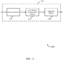
- a block diagram 1200 illustrates a device 1205 for use in wireless communications in accordance with various embodiments.
- the device 1205 may be an example of one or more aspects of the base stations 105, 205, and/or 505 described with reference to FIGs. 1 , 2A , 2B and/or 5, and/or one or more aspects of the core network 130 described with reference to FIG. 1 .
- the device 1205 may also be a processor.
- the device 1205 may include a receiver module 1210, a CCA priority determination module 1215, and/or a transmitter module 1220. Each of these components may be in communication with each other.
- the components of the device 1205 may, individually or collectively, be implemented with one or more application-specific integrated circuits (ASICs) adapted to perform some or all of the applicable functions in hardware.
- ASICs application-specific integrated circuits
- the functions may be performed by one or more other processing units (or cores), on one or more integrated circuits.
- other types of integrated circuits e.g., Structured/Platform ASICs, Field Programmable Gate Arrays (FPGAs), and other Semi-Custom ICs), which may be programmed in any manner known in the art.
- the functions of each unit may also be implemented, in whole or in part, with instructions embodied in a memory, formatted to be executed by one or more general or application-specific processors.
- the receiver module 1210 may be or include a radio frequency (RF) receiver, such as an RF receiver operable to receive transmissions in a licensed spectrum and/or an unlicensed spectrum.
- the receiver module 1210 may be or include a wired receiver.
- the receiver module 1210 may be used to receive various types of data and/or control signals ( i.e., transmissions) over one or more communication links of a wireless or wired communications system, such as one or more communication links of the wireless communications system 100, 200, 250, and/or 500 described with reference to FIGs. 1 , 2A , 2B , and/or 5.
- the transmitter module 1220 may be or include an RF transmitter, such as an RF transmitter operable to transmit in the licensed spectrum and/or the unlicensed spectrum. In other embodiments, the transmitter module 1220 may be or include a wired transmitter. The transmitter module 1220 may be used to transmit various types of data and/or control signals ( i.e., transmissions) over one or more communication links of a wireless communications system, such as one or more communication links of the wireless communications system 100, 200, 250, and/or 500 described with reference to FIGs. 1 , 2A , 2B , and/or 5.
- a wireless communications system such as one or more communication links of the wireless communications system 100, 200, 250, and/or 500 described with reference to FIGs. 1 , 2A , 2B , and/or 5.
- the CCA priority determination module 1215 may be used to prioritize a group of operators needing to perform a CCA for a shared spectrum.
- the CCA priority determination module 1215 may in some cases implement one or more of the prioritization techniques described with reference to FIGs. 7A , 7B , 7C , 7D , and/or 8B.
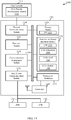
- FIG. 13 a block diagram 1300 is shown that illustrates a base station 1305 configured for wireless communications over a shared spectrum.
- the base station 1305 may be an example of one or more aspects of the base stations or devices 105, 205, 255, 505, 1005, and/or 1055 described with reference to FIGs. 1 , 2A , 2B , 5 , 10A , and/or 10B.
- the base station 1305 may be configured to implement at least some of the features and functions described with reference to FIGs.
- the base station 1305 may include a processor module 1310, a memory module 1320, at least one transceiver module (represented by transceiver module(s) 1355), at least one antenna (represented by antenna(s) 1360), and/or a base station shared spectrum module 1370.
- the base station 1305 may also include one or both of a base station communications module 1330 and a network communications module 1340. Each of these components may be in communication with each other, directly or indirectly, over one or more buses 1335.
- the memory module 1320 may include random access memory (RAM) and/or read-only memory (ROM).
- the memory module 1320 may store computer-readable, computer-executable software (SW) code 1325 containing instructions that are configured to, when executed, cause the processor module 1310 to perform various functions described herein for conducting (or performing CCA for) wireless communications in a shared spectrum.
- SW software
- the software code 1325 may not be directly executable by the processor module 1310 but be configured to cause the base station 1305, e.g., when compiled and executed, to perform various of the functions described herein.
- the processor module 1310 may include an intelligent hardware device, e.g., a central processing unit (CPU), a microcontroller, an ASIC, etc.
- the processor module 1310 may process information received through the transceiver module(s) 1355, the base station communications module 1330, and/or the network communications module 1340.
- the processor module 1310 may also process information to be sent to the transceiver module(s) 1355 for transmission through the antenna(s) 1360, to the base station communications module 1330 for transmission to one or more other base stations or eNBs 1305-a and 1305-b, and/or to the network communications module 1340 for transmission to a core network 1345, which may be an example of aspects of the core network 130 described with reference to FIG. 1 .
- the processor module 1310 may handle, alone or in connection with the base station shared spectrum module 1370, various aspects of conducting (or performing a CCA for) wireless communications in a shared spectrum.
- the transceiver module(s) 1355 may include a modem configured to modulate packets and provide the modulated packets to the antenna(s) 1360 for transmission, and to demodulate packets received from the antenna(s) 1360.
- the transceiver module(s) 1355 may in some cases be implemented as one or more transmitter modules and one or more separate receiver modules.
- the transceiver module(s) 1355 may support communications in a shared spectrum, such as a shared licensed spectrum and/or a shared unlicensed spectrum.
- the transceiver module(s) 1355 may be configured to communicate bi-directionally, via the antenna(s) 1360, with one or more of the UEs or devices 115, 215, and/or 515 described with reference to FIGs.
- the base station 1305 may typically include multiple antennas 1360 (e.g., an antenna array).
- the base station 1305 may communicate with the core network 1345 through the network communications module 1340.
- the base station 1305 may communicate with other base stations or eNBs, such as the eNBs 1305-a and 1305-b, using the base station communications module 1330.
- the base station 1305 may further include a communications management module 1350.
- the communications management module 1350 may manage communications with other base stations, eNBs, and/or devices.
- the communications management module 1350 may be in communication with some or all of the other components of the base station 1305 via the bus or buses 1335.
- functionality of the communications management module 1350 may be implemented as a component of the transceiver module(s) 1355, as a computer program product, and/or as one or more controller elements of the processor module 1310.
- the base station shared spectrum module 1370 may be configured to perform and/or control some or all of the features and/or functions described with reference to FIGs. 1 , 2A , 2B , 3 , 4 , 5 , 6 , 7A-7D , 8A , 8B , 9A , 9B , 10A , 10B , and/or 11 related to conducting (or performing a CCA for) wireless communications in a shared spectrum.
- the base station shared spectrum module 1370 may be configured to support wireless communications in a licensed spectrum and/or a supplemental downlink mode, a carrier aggregation mode, and/or a standalone mode in an unlicensed spectrum.
- the base station shared spectrum module 1370 may include an LTE module 1375 configured to handle LTE communications, an LTE unlicensed module 1380 configured to handle LTE/LTE-A communications in an unlicensed spectrum, and/or an unlicensed module 1385 configured to handle communications other than LTE/LTE-A communications in an unlicensed spectrum.
- the base station shared spectrum module 1370 may also include a CCA module 1390 configured to perform, for example, any of the base station functions described with reference to FIGs. 3 , 4 , 5 , 6 , 7A-7D , 8A , 8B , 9A , 9B , 10A , 10B , and/or 11 for performing a CCA for a shared spectrum.
- the CCA module 1390 may be an example of similar modules (e.g., module 1015 and/or module 1065) described with reference to FIGs. 10A and/or 10B.
- the base station shared spectrum module 1370 or portions of it, may include a processor, and/or some or all of the functionality of the base station shared spectrum module 1370 may be performed by the processor module 1310 and/or in connection with the processor module 1310.
- the core network 1345 may in some cases include a CCA priority determination module 1395.
- the CCA priority determination module 1395 may be used to establish CCA priorities for different operators associated with ( e.g ., configured to communicated over) a shared spectrum of a wireless communications network.
- the CCA priority determination module 1395 may communicate its established priorities to one or more base stations or eNBs 1305, 1305-a, and/or 1305-b.
- the CCA priority determination module 1395 may be an example of aspects of the CCA priority determination module 1215 described with reference to FIG. 12 .
- FIG. 14 a block diagram 1400 is shown that illustrates a UE 1415 configured for wireless communications over a shared spectrum.
- the UE 1415 may have various other configurations and may be included or be part of a personal computer (e.g ., a laptop computer, netbook computer, tablet computer, etc.), a cellular telephone, a PDA, a digital video recorder (DVR), an internet appliance, a gaming console, an e-reader, etc.
- the UE 1415 may in some cases have an internal power supply (not shown), such as a small battery, to facilitate mobile operation.
- the UE 1415 may be an example of one or more of the UEs 115, 215, and/or 515 described with reference to FIGs.
- the UE 1415 may be configured to communicate with one or more of the base stations or devices 105, 205, 255, 505, 1005, 1055, 1205, and/or 1305 described with reference to FIGs. 1 , 2A , 2B , 5 , 10A , 10B , 12 and/or 13.
- the UE 1415 may include a processor module 1410, a memory module 1420, at least one transceiver module (represented by transceiver module(s) 1470), at least one antenna (represented by antenna(s) 1480), and/or a UE shared spectrum module 1440. Each of these components may be in communication with each other, directly or indirectly, over one or more buses 1435.
- the memory module 1420 may include RAM and/or ROM.
- the memory module 1420 may store computer-readable, computer-executable software (SW) code 1425 containing instructions that are configured to, when executed, cause the processor module 1410 to perform various functions described herein for conducting (or performing a CCA for) wireless communications in a shared spectrum.
- the executed instructions may cause the processor module 1410 to perform a CCA similarly to how one of the devices 1005 and/or 1055 described with reference to FIGs. 10A and/or 10B performs a CCA.
- the software code 1425 may not be directly executable by the processor module 1410 but be configured to cause the UE 1415 ( e.g., when compiled and executed) to perform various of the UE functions described herein.
- the processor module 1410 may include an intelligent hardware device, e.g., a CPU, a microcontroller, an ASIC, etc.
- the processor module 1410 may process information received through the transceiver module(s) 1470 and/or information to be sent to the transceiver module(s) 1470 for transmission through the antenna(s) 1480.
- the processor module 1410 may handle, alone or in connection with the UE shared spectrum module 1440, various aspects of conducting (or performing a CCA for) wireless communications in a shared spectrum. In some cases, the processor module 1410 may perform a CCA similarly to how one of the devices 1005 and/or 1055 described with reference to FIGs. 10A and/or 10B performs a CCA.
- the transceiver module(s) 1470 may be configured to communicate bi-directionally with base stations.
- the transceiver module(s) 1470 may be implemented as one or more transmitter modules and one or more separate receiver modules.
- the transceiver module(s) 1470 may support communications in a shared spectrum, such as a shared licensed spectrum and/or a shared unlicensed spectrum.
- the transceiver module(s) 1470 may include a modem configured to modulate packets and provide the modulated packets to the antenna(s) 1480 for transmission, and to demodulate packets received from the antenna(s) 1480. While the UE 1415 may include a single antenna, there may be embodiments in which the UE 1415 may include multiple antennas 1480.
- the UE 1415 may further include a communications management module 1430.
- the communications management module 1430 may manage communications with various base stations or eNBs.
- the communications management module 1430 may be a component of the UE 1415 in communication with some or all of the other components of the UE 1415 over the one or more buses 1435.
- functionality of the communications management module 1430 may be implemented as a component of the transceiver module(s) 1470, as a computer program product, and/or as one or more controller elements of the processor module 1410.
- the UE shared spectrum module 1440 may be configured to perform and/or control some or all of the features and/or functions described with reference to FIGs. 1 , 2A , 2B , 3 , 4 , 5 , 6 , 7A-7D , 8A , 8B , 9A , 9B , 10A , 10B , and/or 11 related to conducting (or performing a CCA for) wireless communications in a shared spectrum.
- the UE shared spectrum module 1440 may be configured to support wireless communications in a licensed spectrum (e.g ., an LTE spectrum) and/or a supplemental downlink mode, a carrier aggregation mode, and/or a standalone mode in an unlicensed spectrum.
- the UE shared spectrum module 1440 may include an LTE module 1445 configured to handle LTE communications, an LTE unlicensed module 1450 configured to handle LTE communications in an unlicensed spectrum, and/or an unlicensed module 1455 configured to handle communications other than LTE communications in an unlicensed spectrum.
- the UE shared spectrum module 1440 may also include a UE CCA module 1460 configured to perform, for example, a CCA similarly to how one of the devices 1005 and/or 1055 described with reference to FIGs. 10A and/or 10B performs a CCA.
- the UE CCA module 1460 may be configured similarly to the modules ( e.g ., module 1015 and/or module 1065) described with reference to FIGs. 10A and/or 10B.
- the UE shared spectrum module 1440, or portions of it, may include a processor, and/or some or all of the functionality of the UE shared spectrum module 1440 may be performed by the processor module 1410 and/or in connection with the processor module 1410.
- FIG. 15 a block diagram of a multiple-input multiple-output (MIMO) communications system 1500 is shown including a base station 1505 and a UE 1515.
- the base station 1505 and the UE 1515 may support LTE-based communications using a licensed and/or unlicensed spectrum.
- the base station 1505 may be an example of one or more aspects of the base stations or devices 105, 205, 255, 505, 1005, 1055, 1205, and/or 1305 described with reference to FIGs.
- the UE 1515 may be an example of one or more aspects of the UEs 115, 215, 515, and/or 1415 described with reference to FIGs. 1 , 2A , 2B , 5 , and/or 14, and/or one of the devices 1005 and/or 1055 described with reference to FIG. 10A and/or 10B.
- the system 1500 may illustrate aspects of the wireless communications system 100, 200, and/or 250 described with reference to FIGs. 1 , 2A , and/or 2B.
- the base station 1505 may be equipped with antennas 1534-a through 1534-x, and the UE 1515 may be equipped with antennas 1552-a through 1552-n.
- the base station 1505 may be able to send data over multiple communication links at the same time.
- Each communication link may be called a "layer” and the "rank" of the communication link may indicate the number of layers used for communication. For example, in a 2x2 MIMO system where base station 1505 transmits two "layers," the rank of the communication link between the base station 1505 and the UE 1515 may be two.
- a transmit (Tx) processor 1520 communicatively coupled with a transmit memory 1542 may receive data from a data source.
- the transmit processor 1520 may process the data.
- the transmit processor 1520 may also generate reference symbols and/or a cell-specific reference signal.
- a transmit (Tx) MIMO processor 1530 may perform spatial processing (e.g., precoding) on data symbols, control symbols, and/or reference symbols, if applicable, and may provide output symbol streams to the transmit (Tx) modulators 1532-a through 1532-x.
- Each modulator 1532 may process a respective output symbol stream (e.g ., for OFDM, etc.) to obtain an output sample stream.
- Each modulator 1532 may further process (e.g ., convert to analog, amplify, filter, and upconvert) the output sample stream to obtain a downlink (DL) signal.
- DL signals from modulators 1532-a through 1532-x may be transmitted via the antennas 1534-a through 1534-x, respectively.
- the antennas 1552-a through 1552-n may receive the DL signals from the base station 1505 and may provide the received signals to the receive (Rx) demodulators 1554-a through 1554-n, respectively.
- Each demodulator 1554 may condition (e.g., filter, amplify, downconvert, and digitize) a respective received signal to obtain input samples.
- Each demodulator 1554 may further process the input samples (e.g ., for OFDM, etc.) to obtain received symbols.
- a MIMO detector 1556 may obtain received symbols from all the demodulators 1554-a through 1554-n, perform MIMO detection on the received symbols if applicable, and provide detected symbols.
- a receive (Rx) processor 1558 may process (e.g ., demodulate, deinterleave, and decode) the detected symbols, providing decoded data for the UE 1515 to a data output, and provide decoded control information to a processor 1580, or memory 1582.
- a transmit (Tx) processor 1564 may receive and process data from a data source.
- the transmit processor 1564 may also generate reference symbols for a reference signal.
- the symbols from the transmit processor 1564 may be precoded by a transmit (Tx) MIMO processor 1566 if applicable, further processed by the transmit (Tx) modulators 1554-a through 1554-n ( e.g., for SC-FDMA, etc.), and be transmitted to the base station 1505 in accordance with the transmission parameters received from the base station 1505.
- the UL signals from the UE 1515 may be received by the antennas 1534, processed by the receiver (Rx) demodulators 1532, detected by a MIMO detector 1536 if applicable, and further processed by a receive (Rx) processor 1538.
- the receive processor 1538 may provide decoded data to a data output and to the processor 1540.
- the processors 1540 and 1580 may include respective modules or functions 1541, 1581 for performing a CCA for a shared spectrum prior to communicating over the shared spectrum.
- the modules or functions 1541, 1581 may be examples of one or more aspects of the CCA module 1015 and/or 1065 described with reference to FIGs. 10A and/or 10B, the CCA opportunity identification module 1075 and 1105 described with reference to FIGs. 10B and/or 11, and/or the CCA performance module 1080 described with reference to FIG. 10B .
- the base station 1505 may use the module or function 1541 to perform a CCA in conjunction with the performance of a CCA by other base stations, while the UE 1515 may use the module or function 1581 to perform a CCA in conjunction with the performance of a CCA by other UEs.
- the base station 1505 and UE 1515 may only communicate with one another over a shared spectrum after each of the base station 1505 and UE 1515 has performed a successful CCA.
- the base station 1505 and UE 1515 may only communicate with one another over a shared spectrum after each of the base station 1505 and UE 1515 has performed a successful CCA for each communication channel to be used by the base station 1505 and UE 1515 during their communications.
- the components of the base station 1505 may, individually or collectively, be implemented with one or more ASICs adapted to perform some or all of the applicable functions in hardware.
- Each of the noted modules may be a means for performing one or more functions related to operation of the system 1500.
- the components of the UE 1515 may, individually or collectively, be implemented with one or more ASICs adapted to perform some or all of the applicable functions in hardware.
- Each of the noted components may be a means for performing one or more functions related to operation of the system 1500.
- FIG. 16 is a flowchart illustrating an example of a method 1600 for wireless communications.
- the method 1600 is described below with reference to one of the base stations or devices 105, 205, 505, 1005, 1055, 1205, 1305, and/or 1505 described with reference to FIGs. 1 , 2A , 2B , 5 , 10A , 10B , 12 , 13 , and/or 15.
- a base station or device 105, 205, 505, 1005, 1055, 1205, 1305, and/or 1505 may execute one or more sets of codes to control the functional elements of the base station or device 105, 205, 505, 1005, 1055, 1205, 1305, and/or 1505 to perform the functions described below.
- an opportunity may be identified for a first operator to perform a CCA for a shared spectrum.
- the shared spectrum may include a licensed and/or unlicensed spectrum.
- the opportunity may be identified based on a priority of the first operator with respect to at least one other operator associated with the shared spectrum.
- the operation(s) at block 1605 may in some cases be performed using the CCA module 1015, 1065, 1390, and/or 1541 described with reference to FIGs. 10A , 10B , 13 , and/or 15, and/or the CCA opportunity identification module 1075 and/or 1105 described with reference to FIGs. 10B and/or 11.
- the opportunity for the first operator to perform a CCA for the shared spectrum may be identified from among two or more CCA slots occupying two or more time periods. In other embodiments, the opportunity for the first operator to perform a CCA for the shared spectrum may be identified from among two or more CCA slots occupying two or more frequency tones associated with different priorities. In further embodiments, the opportunity for the first operator to perform a CCA for the shared spectrum may be identified from among two or more CCA slots occupying a combination of both different time periods and different frequency tones.
- the priority of the first operator with respect to the at least one other operator may be specific to a particular spectrum assigned to a carrier. That is, the first operator may be the only operator having a priority with respect to the at least one other operator for the particular spectrum. In other embodiments, the priority of the first operator with respect to the at least one other operator may be shared by other operators. That is, the first operator may have the same priority as another operator (e.g., a second operator) with respect to the at least one other operator. The latter may be achieved using orthogonal transmissions and/or other techniques for sharing a same spectrum.
- First and second operators may also share the same priority with respect to the at least one other operator by, for example, alternating the priority given the first and second operators in alternating transmission intervals, such that, over time, each of the first and second operators is provided the same priority with respect to the same spectrum.
- the prioritization may be performed separately or jointly across the two or more carriers.
- the CCA for the shared spectrum may be performed during the identified opportunity to determine whether the shared spectrum is available for a transmission during a transmission interval.
- the operation(s) at block 1610 may in some cases be performed using the CCA module 1015, 1065, 1390, and/or 1541 described with reference to FIGs. 10A , 10B , 13 , and/or 15, and/or the CCA performance module 1080 described with reference to FIG. 10B .
- the transmission interval may include a frame or a subframe and the first and at least one other operator may be synchronized with respect to a frame timing or a subframe timing.
- the first and at least one other operator may utilize a same frame structure or subframe structure for the shared spectrum.
- the first and at least one other operator may utilize two or more different frame structures or subframe structures for the shared spectrum.
- the first operator may be capable of transmitting over two or more carriers (e.g ., two or more frequency tones) and the opportunity for the first operator to perform a CCA for the shared spectrum at block 1605 may be an opportunity for the first operator to perform a CCA for a first carrier of the shared spectrum.
- a second opportunity for the first operator to perform a CCA may be identified.
- the second opportunity may be an opportunity for the first operator to perform a CCA for a second carrier of the shared spectrum.
- the second opportunity may be based on 1) the priority of the first operator with respect to the at least one other operator, or 2) a second priority of the first operator with respect to the at least one other operator, wherein the second priority is different from the first priority.
- the first and second priorities may be determined using the same or different techniques (e.g ., one or more of the various techniques described with reference to FIGs. 7A , 7B , 7C , 7D , and/or 8B).
- the CCA may be performed for the second carrier of the shared spectrum during the identified second opportunity to determine whether the shared spectrum is available for a transmission during the transmission interval.
- the method 1600 may provide for wireless communications. It should be noted that the method 1600 is just one implementation and that the operations of the method 1600 may be rearranged or otherwise modified such that other implementations are possible.
- FIG. 17 is a flowchart illustrating another example of a method 1700 for wireless communications.
- the method 1700 is described below with reference to one of the base stations or devices 105, 205, 505, 1005, 1055, 1205, 1305, and/or 1505 described with reference to FIGs. 1 , 2A , 2B , 5 , 10A , 10B , 12 , 13 , and/or 15.
- a base station or device 105, 205, 505, 1005, 1055, 1205, 1305, and/or 1505 may execute one or more sets of codes to control the functional elements of the base station or device 105, 205, 505, 1005, 1055, 1205, 1305, and/or 1505 to perform the functions described below.
- a CCA opportunity may be identified for a first operator to perform a CCA for a shared spectrum.
- the shared spectrum may include a licensed and/or unlicensed spectrum.
- the CCA opportunity may be identified from a subset of CCA slots in a subframe.
- the subset of CCA slots may be based on a priority of the first operator with respect to at least one other operator associated with the shared spectrum.
- the operation(s) at block 1705 may in some cases be performed using the CCA module 1015, 1065, 1390, and/or 1541 described with reference to FIGs. 10A , 10B , 13 , and/or 15, the CCA opportunity identification module 1075 and/or 1105 described with reference to FIGs. 10B and/or 11, and/or the time/frequency CCA slot identification module 1115 described with reference to FIG. 11 .
- the CCA opportunity for the first operator may be earlier in the subframe than a CCA opportunity for the at least one other operator (e.g ., as described with reference to FIG. 7A ).
- the CCA opportunity for the first operator may be later in the subframe than the CCA opportunity for the at least one other operator.
- the subset of CCA slots may include two or more CCA slots occupying two or more time periods. In other embodiments, the subset of CCA slots may include two or more frequency tones associated with different priorities. In further embodiments, the CCA slots may occupy a combination of both different time periods and different frequency tones.
- the priority of the first operator with respect to the at least one other operator may be specific to a particular spectrum assigned to a carrier. That is, the first operator may be the only operator having a priority with respect to the at least one other operator for the particular spectrum. In other embodiments, the priority of the first operator with respect to the at least one other operator may be shared by other operators. That is, the first operator may have the same priority as another operator (e.g., a second operator) with respect to the at least one other operator. The latter may be achieved using orthogonal transmissions and/or other techniques for sharing a same spectrum.
- First and second operators may also share the same priority with respect to the at least one other operator by, for example, alternating the priority given the first and second operators in alternating transmission intervals, such that, over time, each of the first and second operators is provided the same priority with respect to the same spectrum.
- the prioritization may be performed separately or jointly across the two or more carriers.
- the CCA for the shared spectrum may be performed within the identified CCA opportunity to determine whether the shared spectrum is available for a transmission during a transmission interval.
- the operation(s) at block 1710 may in some cases be performed using the CCA module 1015, 1065, 1390, and/or 1541 described with reference to FIGs. 10A , 10B , 13 , and/or 15, and/or the CCA performance module 1080 described with reference to FIG. 10B .
- the transmission interval may include a frame or a subframe and the first and at least one other operator may be synchronized with respect to a frame timing or a subframe timing.
- the first and at least one other operator may utilize a same frame structure or subframe structure for the shared spectrum.
- the first and at least one other operator may utilize two or more different frame structures or subframe structures for the shared spectrum.
- the first operator may be capable of transmitting over two or more carriers (e.g ., two or more frequency tones) and the CCA opportunity identified for the first operator to perform the CCA for the shared spectrum, at block 1705, may be a CCA slot for the first operator to perform a CCA for a first carrier of the shared spectrum.
- a second CCA opportunity for the first operator to perform a CCA may be identified.
- the second CCA opportunity may be a CCA slot for the first operator to perform a CCA for a second carrier of the shared spectrum.
- the second CCA opportunity may be based on 1) the priority of the first operator with respect to the at least one other operator, or 2) a second priority of the first operator with respect to the at least one other operator, wherein the second priority is different from the first priority.
- the first and second priorities may be determined using the same or different techniques (e.g ., one or more of the various techniques described with reference to FIGs. 7A , 7B , 7C , 7D , and/or 8B).
- the CCA may be performed for the second carrier of the shared spectrum in the identified second CCA opportunity to determine whether the shared spectrum is available for a transmission during the transmission interval.
- the method 1700 may provide for wireless communications. It should be noted that the method 1700 is just one implementation and that the operations of the method 1700 may be rearranged or otherwise modified such that other implementations are possible.
- FIG. 18 is a flowchart illustrating another example of a method 1800 for wireless communications.
- the method 1800 is described below with reference to one of the base stations or devices 105, 205, 505, 1005, 1055, 1205, 1305, and/or 1505 described with reference to FIGs. 1 , 2A , 2B , 5 , 10A , 10B , 12 , 13 , and/or 15.
- a base station or device 105, 205, 505, 1005, 1055, 1205, 1305, and/or 1505 may execute one or more sets of codes to control the functional elements of the base station or device 105, 205, 505, 1005, 1055, 1205, 1305, and/or 1505 to perform the functions described below.
- a CCA opportunity may be identified for a first operator to perform a CCA for a shared spectrum.
- the shared spectrum may include a licensed and/or unlicensed spectrum.
- the CCA opportunity may be identified from a subset of CCA slots in a subframe.
- the subset of CCA slots may be based on a priority of the first operator with respect to at least one other operator associated with the shared spectrum.
- the CCA opportunity may also be identified based on a restricted hopping technique described herein with respect to FIG. 7B .
- the operation(s) at block 1805 may in some cases be performed using the CCA module 1015, 1065, 1390, and/or 1541 described with reference to FIGs.
- the subset of CCA slots associated with the priority of the first operator may ensure that the first operator has CCA priority in more transmission intervals than the at least one other operator.
- FIG. 7B illustrates an example in which a first operator has CCA priority over a second operator in two out of every three transmission intervals.
- the subset of CCA slots associated with the priority of the first operator may provide the first operator with CCA priority in fewer transmission intervals than the at least one other operator.
- the subset of CCA slots may include two or more CCA slots occupying two or more time periods. In other embodiments, the subset of CCA slots may include two or more frequency tones associated with different priorities. In further embodiments, the CCA slots may occupy a combination of both different time periods and different frequency tones.
- the priority of the first operator with respect to the at least one other operator may be specific to a particular spectrum assigned to a carrier. That is, the first operator may be the only operator having a priority with respect to the at least one other operator for the particular spectrum. In other embodiments, the priority of the first operator with respect to the at least one other operator may be shared by other operators. That is, the first operator may have the same priority as another operator (e.g., a second operator) with respect to the at least one other operator. The latter may be achieved using orthogonal transmissions and/or other techniques for sharing a same spectrum.
- First and second operators may also share the same priority with respect to the at least one other operator by, for example, alternating the priority given the first and second operators in alternating transmission intervals, such that, over time, each of the first and second operators is provided the same priority with respect to the same spectrum.
- the prioritization may be performed separately or jointly across the two or more carriers.
- the CCA for the shared spectrum may be performed within the identified CCA opportunity to determine whether the shared spectrum is available for a transmission during a transmission interval.
- the operation(s) at block 1810 may in some cases be performed using the CCA module 1015, 1065, 1390, and/or 1541 described with reference to FIGs. 10A , 10B , 13 , and/or 15, and/or the CCA performance module 1080 described with reference to FIG. 10B .
- the transmission interval may include a frame or a subframe and the first and at least one other operator may be synchronized with respect to a frame timing or a subframe timing.
- the first and at least one other operator may utilize a same frame structure or subframe structure for the shared spectrum.
- the first and at least one other operator may utilize two or more different frame structures or subframe structures for the shared spectrum.
- the first operator may be capable of transmitting over two or more carriers (e.g ., two or more frequency tones) and the CCA opportunity identified for the first operator to perform the CCA for the shared spectrum, at block 1805, may be a CCA slot for the first operator to perform a CCA for a first carrier of the shared spectrum.
- a second CCA opportunity for the first operator to perform a CCA may be identified.
- the second CCA opportunity may be a CCA slot for the first operator to perform a CCA for a second carrier of the shared spectrum.
- the second CCA opportunity may be based on 1) the priority of the first operator with respect to the at least one other operator, or 2) a second priority of the first operator with respect to the at least one other operator, wherein the second priority is different from the first priority.
- the first and second priorities may be determined using the same or different techniques (e.g ., one or more of the various techniques described with reference to FIG. 7A , 7B , 7C , 7D , and/or 8B).
- the CCA may be performed for the second carrier of the shared spectrum in the identified second CCA opportunity to determine whether the shared spectrum is available for a transmission during the transmission interval.
- the method 1800 may provide for wireless communications. It should be noted that the method 1800 is just one implementation and that the operations of the method 1800 may be rearranged or otherwise modified such that other implementations are possible.
- FIG. 19 is a flowchart illustrating another example of a method 1900 for wireless communications.
- the method 1900 is described below with reference to one of the base stations or devices 105, 205, 505, 1005, 1055, 1205, 1305, and/or 1505 described with reference to FIGs. 1 , 2A , 2B , 5 , 10A , 10B , 12 , 13 , and/or 15.
- a base station or device 105, 205, 505, 1005, 1055, 1205, 1305, and/or 1505 may execute one or more sets of codes to control the functional elements of the base station or device 105, 205, 505, 1005, 1055, 1205, 1305, and/or 1505 to perform the functions described below.
- a transmission interval of a shared spectrum may be identified.
- the shared spectrum may include a licensed and/or unlicensed spectrum.
- the transmission interval may be identified by a frame number, or as a transmission interval associated with an even or an odd frame number.
- the operation(s) at block 1905 may in some cases be performed using the CCA module 1015, 1065, 1390, and/or 1541 described with reference to FIGs. 10A , 10B , 13 , and/or 15, the CCA opportunity identification module 1075 and/or 1105 described with reference to FIGs. 10B and/or 11, and/or the transmission interval identification module 1120 described with reference to FIG. 11 .
- a CCA opportunity may be identified for a first operator to perform a CCA for the identified transmission interval.
- the CCA opportunity may be identified from a set of CCA slots in a subframe.
- the CCA opportunity may also be identified based on a restricted transmission technique described herein with respect to FIG. 7C .
- the operation(s) at block 1910 may in some cases be performed using the CCA module 1015, 1065, 1390, and/or 1541 described with reference to FIGs. 10A , 10B , 13 , and/or 15, the CCA opportunity identification module 1075 and/or 1105 described with reference to FIGs. 10B and/or 11, and/or the time/frequency CCA slot identification module 1115 and/or restricted hopping management module 1125 described with reference to FIG. 11 .
- the set of CCA slots may include two or more CCA slots occupying two or more time periods. In other embodiments, the set of CCA slots may include two or more frequency tones associated with different priorities. In further embodiments, the CCA slots may occupy a combination of both different time periods and different frequency tones.
- the priority of the first operator with respect to the at least one other operator may be specific to a particular spectrum assigned to a carrier. That is, the first operator may be the only operator having a priority with respect to the at least one other operator for the particular spectrum. In other embodiments, the priority of the first operator with respect to the at least one other operator may be shared by other operators. That is, the first operator may have the same priority as another operator (e.g., a second operator) with respect to the at least one other operator. The latter may be achieved using orthogonal transmissions and/or other techniques for sharing a same spectrum.
- First and second operators may also share the same priority with respect to the at least one other operator by, for example, alternating the priority given the first and second operators in alternating transmission intervals, such that, over time, each of the first and second operators is provided the same priority with respect to the same spectrum.
- the prioritization may be performed separately or jointly across the two or more carriers.
- the operation(s) at block 1915 may in some cases be performed using the CCA module 1015, 1065, 1390, and/or 1541 described with reference to FIGs. 10A , 10B , 13 , and/or 15, the CCA opportunity identification module 1075 and/or 1105 described with reference to FIGs. 10B and/or 11, and/or the restricted transmission management module 1130 described with reference to FIG. 11 .
- FIG. 7C illustrates an example in which a first operator has no restrictions on performing a CCA, while a second operator is restricted from performing a CCA in every other transmission interval ( e.g ., every other frame).
- the same restricted transmission technique may be used for operators having different priorities over other operators, because the priority of one operator over another operator in a shared spectrum may be controlled by restricting one or more operators from performing a CCA for a particular transmission interval of the shared spectrum.
- the CCA for the identified transmission interval of the shared spectrum may be performed within the identified CCA opportunity, to determine whether the shared spectrum is available for a transmission during the identified transmission interval.
- the operation(s) at block 1920 may in some cases be performed using the CCA module 1015, 1065, 1390, and/or 1541 described with reference to FIGs. 10A , 10B , 13 , and/or 15, and/or the CCA performance module 1080 described with reference to FIG. 10B .
- the method 1900 may proceed to block 1925.
- the method 1900 waits to perform a CCA for a next transmission interval of the shared spectrum, and then returns to block 1905.
- the transmission interval may include a frame or a subframe and the first and at least one other operator may be synchronized with respect to a frame timing or a subframe timing.
- the first and at least one other operator may utilize a same frame structure or subframe structure for the shared spectrum.
- the first and at least one other operator may utilize two or more different frame structures or subframe structures for the shared spectrum.
- the first operator may be capable of transmitting over two or more carriers (e.g ., two or more frequency tones) and the CCA opportunity identified for the first operator to perform the CCA for the identified transmission interval of the shared spectrum, at block 1910, may be a CCA opportunity for the first operator to perform a CCA for a first carrier of the shared spectrum.
- a second CCA opportunity for the first operator to perform a CCA may be identified.
- the second CCA opportunity may be a CCA slot for the first operator to perform a CCA for a second carrier of the shared spectrum.
- the second CCA opportunity may be based on 1) the priority of the first operator with respect to the at least one other operator, or 2) a second priority of the first operator with respect to the at least one other operator, wherein the second priority is different from the first priority.
- the first and second priorities may be determined using the same or different techniques (e.g ., one or more of the various techniques described with reference to FIG. 7A , 7B , 7C , 7D , and/or 8B).
- the CCA may be performed for the second carrier of the shared spectrum in the identified second CCA opportunity to determine whether the shared spectrum is available for a transmission during the identified transmission interval.
- the method 1900 may provide for wireless communications. It should be noted that the method 1900 is just one implementation and that the operations of the method 1900 may be rearranged or otherwise modified such that other implementations are possible.
- the priority of a first operator with respect to at least one other operator may not restrict the first operator from performing a CCA for a transmission period of a shared spectrum during a subframe, but may instead place a restriction on the at least one other operator from performing a CCA during the subframe.
- FIG. 20 is a flowchart illustrating another example of a method 2000 for wireless communications.
- the method 2000 is described below with reference to one of the base stations or devices 105, 205, 505, 1005, 1055, 1205, 1305, and/or 1505 described with reference to FIGs. 1 , 2A , 2B , 5 , 10A , 10B , 12 , 13 , and/or 15.
- a base station or device 105, 205, 505, 1005, 1055, 1205, 1305, and/or 1505 may execute one or more sets of codes to control the functional elements of the base station or device 105, 205, 505, 1005, 1055, 1205, 1305, and/or 1505 to perform the functions described below.
- a number of CCA opportunities may be identified for a first operator to perform a CCA for a shared spectrum.
- the number of CCA opportunities may be based on a priority of the first operator with respect to at least one other operator associated with the shared spectrum.
- the number of CCA opportunities may be identified from a set of CCA slots in a subframe.
- the shared spectrum may include a licensed and/or unlicensed spectrum.
- the operation(s) at block 2005 may in some cases be performed using the CCA module 1015, 1065, 1390, and/or 1541 described with reference to FIGs. 10A , 10B , 13 , and/or 15, the CCA opportunity identification module 1075 and/or 1105 described with reference to FIGs. 10B and/or 11, and/or the time/frequency CCA slot identification module 1115 and/or the multiple CCA slot management module 1135 described with reference to FIG. 11 .
- two or more of the identified CCA opportunities may be adjacent in time.
- each of the identified CCA slots may be separated from another one or ones of the identified CCA opportunities by one or more non-identified CCA opportunities.
- the number of CCA opportunities associated with the priority of the first operator may ensure that the first operator is allotted more CCA slots than the at least one other operator (e.g., the number of CCA slots allotted to the first operator in a subframe may be greater than a number of CCA slots allotted to the at least one other operator in the subframe).
- the number of CCA opportunities associated with the priority of the first operator may provide the first operator with fewer CCA slots than the at least one other operator.
- the number of CCA opportunities may include two or more CCA slots occupying two or more time periods. In some embodiments, the number of CCA opportunities may occupy a combination of both different time periods and different frequency tones.
- the priority of the first operator with respect to the at least one other operator may be specific to a particular spectrum assigned to a carrier. That is, the first operator may be the only operator having a priority with respect to the at least one other operator for the particular spectrum. In other embodiments, the priority of the first operator with respect to the at least one other operator may be shared by other operators. That is, the first operator may have the same priority as another operator (e.g., a second operator) with respect to the at least one other operator. The latter may be achieved using orthogonal transmissions and/or other techniques for sharing a same spectrum.
- First and second operators may also share the same priority with respect to the at least one other operator by, for example, alternating the priority given the first and second operators in alternating transmission intervals, such that, over time, each of the first and second operators is provided the same priority with respect to the same spectrum.
- the prioritization may be performed separately or jointly across the two or more carriers.
- the CCA for the shared spectrum may be performed within a next of the identified CCA opportunities (and possibly the only identified CCA opportunity, if only one CCA opportunity is identified) to determine whether the shared spectrum is available for a transmission during a transmission interval.
- the operation(s) at block 2010 may in some cases be performed using the CCA module 1015, 1065, 1390, and/or 1541 described with reference to FIGs. 10A , 10B , 13 , and/or 15, and/or the CCA performance module 1080 described with reference to FIG. 10B .
- the transmission interval may include a frame or a subframe and the first and at least one other operator may be synchronized with respect to a frame timing or a subframe timing.
- the first and at least one other operator may utilize a same frame structure or subframe structure for the shared spectrum.
- the first and at least one other operator may utilize two or more different frame structures or subframe structures for the shared spectrum.
- processing may proceed to block 2020.
- the method 2000 waits to perform a CCA for a next transmission interval of the shared spectrum, and then returns to block 2005.
- the first operator may be capable of transmitting over two or more carriers (e.g ., two or more frequency tones) and the number of CCA opportunities identified for the first operator to perform the CCA for the shared spectrum, at block 2005, may be a number of CCA opportunities for the first operator to perform a CCA for a first carrier of the shared spectrum.
- a second number of CCA opportunities for the first operator to perform a CCA may be identified.
- the second number of CCA opportunities may be a number of CCA opportunities for the first operator to perform a CCA for a second carrier of the shared spectrum.
- the second number of CCA opportunities may be based on 1) the priority of the first operator with respect to the at least one other operator, or 2) a second priority of the first operator with respect to the at least one other operator, wherein the second priority is different from the first priority.
- the first and second priorities may be determined using the same or different techniques (e.g., one or more of the various techniques described with reference to FIG. 7A , 7B , 7C , 7D , and/or 8B).
- the CCA may be performed for the second carrier of the shared spectrum in each of the identified second number of CCA opportunities to determine whether the shared spectrum is available for a transmission during the transmission interval.
- the method 2000 may provide for wireless communications. It should be noted that the method 2000 is just one implementation and that the operations of the method 2000 may be rearranged or otherwise modified such that other implementations are possible.
- FIG. 21 is a flowchart illustrating another example of a method 2100 for wireless communications.
- the method 2100 is described below with reference to one of the eNBs or devices 105, 205, 505, 1005, 1055, 1305, and/or 1505 described with reference to FIGs. 1 , 2A , 2B , 5 , 10A , 10B , 13 , and/or 15.
- a base station or device 105, 205, 505, 1005, 1055, 1205, 1305, and/or 1505 may execute one or more sets of codes to control the functional elements of the base station or device 105, 205, 505, 1005, 1055, 1205, 1305, and/or 1505 to perform the functions described below.
- a transmission interval of a shared spectrum may be identified.
- the shared spectrum may include a licensed and/or unlicensed spectrum.
- the transmission interval may be identified by a frame number, or as a transmission interval associated with an even or an odd frame number.
- the operation(s) at block 2105 may in some cases be performed using the CCA module 1015, 1065, 1390, and/or 1541 described with reference to FIGs. 10A , 10B , 13 , and/or 15, the CCA opportunity identification module 1075 and/or 1105 described with reference to FIGs. 10B and/or 11, and/or the transmission interval identification module 1120 described with reference to FIG. 11 .
- a number of CCA opportunities may be identified for a first operator to perform a CCA for the identified transmission interval.
- the number of CCA opportunities may be based on a priority of the first operator with respect to at least one other operator associated with the shared spectrum.
- the number of CCA opportunities may be identified from a set of CCA slots in a sub frame.
- the operation(s) at block 2110 may in some cases be performed using the CCA module 1015, 1065, 1390, and/or 1541 described with reference to FIGs. 10A , 10B , 13 , and/or 15, the CCA opportunity identification module 1075 and/or 1105 described with reference to FIGs. 10B and/or 11, and/or the time/frequency CCA slot identification module 1115 and/or the multiple CCA slot management module 1135 described with reference to FIG. 11 .
- two or more of the identified CCA opportunities may be adjacent in time. In other cases, each of the identified CCA opportunities may be separated from another one or ones of the identified CCA opportunities by one or more non-identified CCA opportunities.
- the number of identified CCA opportunities may vary depending on the identity of the transmission interval.
- the first operator may be allotted one CCA slot during even numbered transmission intervals and two CCA slots during odd numbered transmission intervals.
- the number of CCA opportunities associated with the priority of the first operator, over time may ensure that the first operator is allotted more CCA slots than the at least one other operator.
- FIG. 7D illustrates an example in which a first operator is allotted three CCA slots for every two CCA slots allotted to a second operator.
- the number of CCA opportunities associated with the priority of the first operator, over time may provide the first operator with fewer CCA slots than the at least one other operator.
- the number of CCA opportunities may include two or more CCA slots occupying two or more time periods. In some embodiments, the number of CCA opportunities may occupy a combination of both different time periods and different frequency tones.
- the priority of the first operator with respect to the at least one other operator may be specific to a particular spectrum assigned to a carrier. That is, the first operator may be the only operator having a priority with respect to the at least one other operator for the particular spectrum. In other embodiments, the priority of the first operator with respect to the at least one other operator may be shared by other operators. That is, the first operator may have the same priority as another operator (e.g ., a second operator) with respect to the at least one other operator. The latter may be achieved using orthogonal transmissions and/or other techniques for sharing a same spectrum.
- First and second operators may also share the same priority with respect to the at least one other operator by, for example, alternating the priority given the first and second operators in alternating transmission intervals, such that, over time, each of the first and second operators is provided the same priority with respect to the same spectrum.
- the prioritization may be performed separately or jointly across the two or more carriers.
- the CCA for the identified transmission interval of the shared spectrum may be performed within a next of the identified CCA opportunities (and possibly the only identified CCA opportunity, if only one CCA opportunity is identified) to determine whether the transmission interval of the shared spectrum is available for a transmission during a transmission interval.
- the operation(s) at block 2115 may in some cases be performed using the CCA module 1015, 1065, 1390, and/or 1541 described with reference to FIGs. 10A , 10B , 13 , and/or 15, and/or the CCA performance module 1080 described with reference to FIG. 10B .
- the transmission interval may include a frame or a subframe and the first and at least one other operator may be synchronized with respect to a frame timing or a subframe timing.
- the first and at least one other operator may utilize a same frame structure or subframe structure for the shared spectrum.
- the first and at least one other operator may utilize two or more different frame structures or subframe structures for the shared spectrum.
- processing may proceed to block 2125.
- the method 2100 waits to perform a CCA for a next transmission interval of the shared spectrum, and then returns to block 2105.
- the first operator may be capable of transmitting over two or more carriers (e.g ., two or more frequency tones) and the number of CCA opportunities identified for the first operator to perform a CCA for the shared spectrum, at block 2005, may be a number of CCA opportunities for the first operator to perform a CCA for a first carrier of the shared spectrum.
- a second number of CCA opportunities for the first operator to perform a CCA may be identified.
- the second number of CCA opportunities may be a number of CCA opportunities for the first operator to perform a CCA for a second carrier of the shared spectrum.
- the second number of CCA opportunities may be based on 1) the priority of the first operator with respect to the at least one other operator, or 2) a second priority of the first operator with respect to the at least one other operator, wherein the second priority is different from the first priority.
- the first and second priorities may be determined using the same or different techniques (e.g ., one or more of the various techniques described with reference to FIG. 7A , 7B , 7C , 7D , and/or 8B).
- the CCA may be performed for the second carrier of the shared spectrum in each of the identified second number of CCA opportunities to determine whether the shared spectrum is available for a transmission during the transmission interval.
- the method 2100 may provide for wireless communications. It should be noted that the method 2100 is just one implementation and that the operations of the method 2100 may be rearranged or otherwise modified such that other implementations are possible.
- FIG. 22 is a flowchart illustrating another example of a method 2200 for wireless communications.
- the method 2200 is described below with reference to one of the base stations or devices 105, 205, 505, 1005, 1055, 1205, 1305, and/or 1505 described with reference to FIGs. 1 , 2A , 2B , 5 , 10A , 10B , 12 , 13 , and/or 15.
- a base station or device 105, 205, 505, 1005, 1055, 1305, and/or 1505 may execute one or more sets of codes to control the functional elements of the base station or device 105, 205, 505, 1005, 1055, 1205, 1305, and/or 1505 to perform the functions described below.
- a transmission interval of a shared spectrum may be identified.
- the shared spectrum may include a licensed and/or unlicensed spectrum.
- the transmission interval may be identified by a frame number, or as a transmission interval associated with an even or an odd frame number.
- the operation(s) at block 2205 may in some cases be performed using the CCA module 1015, 1065, 1390, and/or 1541 described with reference to FIGs. 10A , 10B , 13 , and/or 15, the CCA opportunity identification module 1075 and/or 1105 described with reference to FIGs. 10B and/or 11, and/or the transmission interval identification module 1120 described with reference to FIG. 11 .
- the operation(s) at block 2210 may in some cases be performed using the CCA module 1015, 1065, 1390, and/or 1541 described with reference to FIGs.
- the first operator may be restricted from transmitting over the shared spectrum for at least one transmission interval, but is not restricted from transmitting over the shared spectrum during every identified transmission interval.
- a first operator may be restricted from transmitting over the shared spectrum during particular subframes ( i.e ., examples of transmission intervals) because the frame structure of the first operator has a silence period which dictates the first operator cannot transmit over the shared spectrum during the particular subframes.
- the frame structure of the first operator may include a silence period that is longer than a silence period for the at least one other operator.
- the frame structure of the first operator may include a silence period that is shorter than a silence period for the at least one other operator.
- an opportunity may be identified for the first operator to perform a CCA for the shared spectrum.
- the opportunity may be identified based on a priority of the first operator with respect to at least one other operator associated with the shared spectrum.
- the operation(s) at block 2215 may in some cases be performed using the CCA module 1015, 1065, 1390, and/or 1541 described with reference to FIGs. 10A , 10B , 13 , and/or 15, and/or the CCA opportunity identification module 1075 and/or 1105 described with reference to FIGs. 10B and/or 11.
- the opportunity for the first operator to perform a CCA for the shared spectrum may be identified from among two or more CCA slots occupying two or more time periods. In other embodiments, the opportunity for the first operator to perform a CCA for the shared spectrum may be identified from among two or more CCA slots occupying two or more frequency tones associated with different priorities. In further embodiments, the opportunity for the first operator to perform a CCA for the shared spectrum may be identified from among two or more CCA slots occupying a combination of both different time periods and different frequency tones.
- the priority of the first operator with respect to the at least one other operator may be specific to a particular spectrum assigned to a carrier. That is, the first operator may be the only operator having a priority with respect to the at least one other operator for the particular spectrum. In other embodiments, the priority of the first operator with respect to the at least one other operator may be shared by other operators. That is, the first operator may have the same priority as another operator (e.g ., a second operator) with respect to the at least one other operator. The latter may be achieved using orthogonal transmissions and/or other techniques for sharing a same spectrum.
- First and second operators may also share the same priority with respect to the at least one other operator by, for example, alternating the priority given the first and second operators in alternating transmission intervals, such that, over time, each of the first and second operators is provided the same priority with respect to the same spectrum.
- the prioritization may be performed separately or jointly across the two or more carriers.
- the CCA for the shared spectrum may be performed during the identified opportunity to determine whether the transmission interval of the shared spectrum is available for a transmission.
- the operation(s) at block 2220 may in some cases be performed using the CCA module 1015, 1065, 1390, and/or 1541 described with reference to FIGs. 10A , 10B , 13 , and/or 15, and/or the CCA performance module 1080 described with reference to FIG. 10B .
- the method 2200 may proceed to block 2225.
- the method 2200 waits to perform a CCA for a next transmission interval of the shared spectrum, and then returns to block 2205.
- the transmission interval may include a frame or a subframe and the first and at least one other operator may be synchronized with respect to a frame timing or a subframe timing.
- the first and at least one other operator may utilize a same frame structure or subframe structure for the shared spectrum.
- the first and at least one other operator may utilize two or more different frame structures or subframe structures for the shared spectrum.
- the first operator may be capable of transmitting over two or more carriers (e.g ., two or more frequency tones) and the opportunity identified for the first operator to perform a CCA for the transmission interval of the shared spectrum at block 2215 may be an opportunity for the first operator to perform a CCA for a first carrier of the shared spectrum.
- a second opportunity for the first operator to perform a CCA may be identified.
- the second opportunity may be an opportunity for the first operator to perform a CCA for a second carrier of the shared spectrum.
- the second opportunity may be based on 1) the priority of the first operator with respect to the at least one other operator, or 2) a second priority of the first operator with respect to the at least one other operator, wherein the second priority is different from the first priority.
- the first and second priorities may be determined using the same or different techniques (e.g ., one or more of the various techniques described with reference to FIG. 7A , 7B , 7C , 7D , and/or 8B).
- the CCA may be performed for the second carrier of the shared spectrum during the identified second opportunity to determine whether the shared spectrum is available for a transmission during the transmission interval.
- the method 2200 may provide for wireless communications. It should be noted that the method 2200 is just one implementation and that the operations of the method 2200 may be rearranged or otherwise modified such that other implementations are possible.
- aspects of the methods 1600, 1700, 1800, 1900, 2000, 2100, and/or 2200 described with reference to FIGs. 16 , 17 , 18 , 19 , 20 , 21 , and/or 22 may be combined.
- different the priority of a first operator with respect to at least one other operator may be determined based on a combination of two or more of the techniques described in FIGs. 16 , 17 , 18 , 19 , 20 , 21 , and/or 22.
- Information and signals may be represented using any of a variety of different technologies and techniques.
- data, instructions, commands, information, signals, bits, symbols, and chips that may be referenced throughout the above description may be represented by voltages, currents, electromagnetic waves, magnetic fields or particles, optical fields or particles, or any combination thereof.
- a general-purpose processor may be a microprocessor, but in the alternative, the processor may be any conventional processor, controller, microcontroller, or state machine.
- a processor may also be implemented as a combination of computing devices, e.g ., a combination of a DSP and a microprocessor, multiple microprocessors, one or more microprocessors in conjunction with a DSP core, or any other such configuration.
- a processor may in some cases be in electronic communication with a memory, where the memory stores instructions that are executable by the processor.
- the functions described herein may be implemented in hardware, software executed by a processor, firmware, or any combination thereof. If implemented in software executed by a processor, the functions may be stored on or transmitted over as one or more instructions or code on a computer-readable medium. Other examples and implementations are within the scope and spirit of the disclosure and appended claims. For example, due to the nature of software, functions described above can be implemented using software executed by a processor, hardware, firmware, hardwiring, or combinations of any of these. Features implementing functions may also be physically located at various positions, including being distributed such that portions of functions are implemented at different physical locations.
- a computer program product or computer-readable medium both include a computer-readable storage medium and communication medium, including any mediums that facilitates transfer of a computer program from one place to another.
- a storage medium may be any medium that can be accessed by a general purpose or special purpose computer.
- computer-readable medium can comprise RAM, ROM, EEPROM, CD-ROM or other optical disk storage, magnetic disk storage or other magnetic storage devices, or any other medium that can be used to carry or store desired computer-readable program code in the form of instructions or data structures and that can be accessed by a general-purpose or special-purpose computer, or a general-purpose or special-purpose processor.
- any connection is properly termed a computer-readable medium.
- Disk and disc include compact disc (CD), laser disc, optical disc, digital versatile disc (DVD), floppy disk and Blu-ray disc where disks usually reproduce data magnetically, while discs reproduce data optically with lasers. Combinations of the above are also included within the scope of computer-readable media.
Applications Claiming Priority (3)
| Application Number | Priority Date | Filing Date | Title |
|---|---|---|---|
| US201361883850P | 2013-09-27 | 2013-09-27 | |
| US14/489,239 US9420472B2 (en) | 2013-09-27 | 2014-09-17 | Prioritization of different operators in shared spectrum |
| PCT/US2014/056224 WO2015047849A2 (en) | 2013-09-27 | 2014-09-18 | Prioritization of different operators in shared spectrum |
Publications (2)
| Publication Number | Publication Date |
|---|---|
| EP3050388A2 EP3050388A2 (en) | 2016-08-03 |
| EP3050388B1 true EP3050388B1 (en) | 2018-07-11 |
Family
ID=52740131
Family Applications (1)
| Application Number | Title | Priority Date | Filing Date |
|---|---|---|---|
| EP14780704.4A Active EP3050388B1 (en) | 2013-09-27 | 2014-09-18 | Prioritization of different operators in shared spectrum |
Country Status (7)
| Country | Link |
|---|---|
| US (2) | US9420472B2 (ko) |
| EP (1) | EP3050388B1 (ko) |
| JP (2) | JP6092475B2 (ko) |
| KR (1) | KR101728648B1 (ko) |
| CN (1) | CN105612802B (ko) |
| BR (1) | BR112016006668B1 (ko) |
| WO (1) | WO2015047849A2 (ko) |
Families Citing this family (54)
| Publication number | Priority date | Publication date | Assignee | Title |
|---|---|---|---|---|
| US9420472B2 (en) * | 2013-09-27 | 2016-08-16 | Qualcomm Incorporated | Prioritization of different operators in shared spectrum |
| US9220115B2 (en) * | 2013-10-23 | 2015-12-22 | Qualcomm Incorporated | Techniques for channel access in asynchronous unlicensed radio frequency spectrum band deployments |
| KR101995104B1 (ko) * | 2014-05-08 | 2019-07-01 | 노키아 솔루션스 앤드 네트웍스 오와이 | 통신 효율성 향상 |
| US10694391B2 (en) * | 2014-08-29 | 2020-06-23 | Sony Corporation | Device and method for controlling use of a frequency band shared by a cellular system and wireless system among multiple base stations |
| WO2016058516A1 (en) * | 2014-10-13 | 2016-04-21 | Huawei Technologies Co., Ltd. | Device, network, and method for communications with carrier sensing and coexistence |
| US10904801B2 (en) * | 2017-02-07 | 2021-01-26 | Qualcomm Incorporated | Multicarrier access for spectrum pooling |
| CN105578580B (zh) * | 2014-11-03 | 2021-06-04 | 北京三星通信技术研究有限公司 | 功率控制、上报和上行发送的方法、用户设备和控制节点 |
| RU2702266C2 (ru) * | 2014-11-07 | 2019-10-07 | Телефонактиеболагет Л М Эрикссон (Пабл) | Первый радиоузел и соответствующий способ выполнения прослушивания перед передачей (lbt) с помощью выбранного способа lbt |
| US9942801B2 (en) * | 2014-12-15 | 2018-04-10 | Qualcomm Incorporated | Techniques for reserving a channel of a radio frequency spectrum |
| CN107071915B (zh) * | 2015-01-29 | 2021-02-02 | 中兴通讯股份有限公司 | 一种数据传输方法、数据传输站点及接收端 |
| CN106160966B (zh) * | 2015-03-30 | 2021-01-26 | 中兴通讯股份有限公司 | 数据发送方法、占用信号的发送方法及装置 |
| CN107660348B (zh) * | 2015-04-08 | 2021-08-13 | 交互数字专利控股公司 | 用于未许可频带中的lte操作的系统和方法 |
| US10051662B2 (en) | 2015-04-15 | 2018-08-14 | Mediatek Inc. | Methods of listen-before-talk mechanism for opportunistic spectrum access |
| US10104691B2 (en) | 2015-04-15 | 2018-10-16 | Mediatek Inc. | Methods of listen-before-talk mechanism for opportunistic spectrum access |
| CN106304369B (zh) * | 2015-05-15 | 2019-08-23 | 上海诺基亚贝尔股份有限公司 | 基于接入优先级的资源竞争的方法及装置 |
| US10349446B2 (en) | 2015-05-22 | 2019-07-09 | Lg Electronics Inc. | Channel sensing in wireless communication system, transmission method based on same, and device therefor |
| CN106301734A (zh) * | 2015-06-29 | 2017-01-04 | 中兴通讯股份有限公司 | 一种非授权载波占用时长的管理方法和装置 |
| TWI618422B (zh) * | 2015-07-07 | 2018-03-11 | 財團法人資訊工業策進會 | 基地台、使用者終端機以及確定共用頻譜之使用之方法 |
| CN105634859B (zh) * | 2015-07-31 | 2019-08-02 | 宇龙计算机通信科技(深圳)有限公司 | 基于负载的lbt信道检测方法及系统、基站和终端 |
| CN106454881B (zh) * | 2015-08-06 | 2021-05-11 | 中兴通讯股份有限公司 | 数据发送、接收方法及装置 |
| CN106452701B (zh) * | 2015-08-07 | 2020-06-09 | 中兴通讯股份有限公司 | 一种非授权多载波先听后说lbt执行方法和装置 |
| JP6804452B2 (ja) * | 2015-08-11 | 2020-12-23 | 京セラ株式会社 | 基地局及び無線端末 |
| EP3372042A1 (en) * | 2015-11-06 | 2018-09-12 | Telefonaktiebolaget LM Ericsson (PUBL) | Communication device |
| EP3410760B1 (en) * | 2016-01-27 | 2020-10-21 | Sony Corporation | Communication control device, communication control method and program |
| US10805953B2 (en) * | 2016-02-04 | 2020-10-13 | Ofinno, Llc | Channel access procedures in a wireless network |
| US10292182B2 (en) | 2016-02-16 | 2019-05-14 | Hfi Innovation Inc. | Listen before talk channel access procedure for uplink LAA |
| US10045376B2 (en) | 2016-02-16 | 2018-08-07 | Mediatek Inc. | Channel access procedure and QoS provisioning for uplink LAA |
| US10708952B2 (en) | 2016-03-29 | 2020-07-07 | Lg Electronics Inc. | Method for transmitting or receiving uplink signal in wireless communication system and device therefor |
| US10187864B2 (en) * | 2016-04-01 | 2019-01-22 | Qualcomm Incorporated | Timing advance design for enhanced component carrier |
| CN105744507B (zh) * | 2016-04-09 | 2019-11-19 | 郭今戈 | 一种终端代理的不同运营商之间通信资源共享的方法、系统 |
| CN107770879B (zh) * | 2016-08-23 | 2020-06-16 | 华为技术有限公司 | 数据传输方法、装置及系统 |
| US10631173B2 (en) * | 2016-09-02 | 2020-04-21 | Qualcomm Incorporated | Radio (NR) procedures for shared spectrum |
| US10536944B2 (en) * | 2016-10-12 | 2020-01-14 | Qualcomm Incorporated | Techniques for contending for access to a radio frequency spectrum band using a coordinated listen before talk procedure |
| US10616845B2 (en) * | 2016-10-13 | 2020-04-07 | Qualcomm Incorporated | Coordinated resource discovery |
| US10645586B2 (en) * | 2016-10-13 | 2020-05-05 | Qualcomm Incorporated | Coordinated resource partitioning |
| US11716751B2 (en) * | 2016-10-19 | 2023-08-01 | Qualcomm Incorporated | Techniques for new radio frame structures for data transmission |
| US10039120B2 (en) * | 2016-10-24 | 2018-07-31 | Qualcomm Incorporated | Scaling of shared spectrum exclusive resources |
| US10206117B2 (en) | 2016-10-26 | 2019-02-12 | Qualcomm Incorporated | Radio shared spectrum access procedures |
| US10609664B2 (en) * | 2016-11-04 | 2020-03-31 | Qualcomm Incorporated | Techniques and apparatuses for frequency division multiplexing (FDM) based medium access on shared spectrum |
| CN108156607B (zh) * | 2016-12-05 | 2021-04-13 | 中国电信股份有限公司 | 频率优先级信息处理方法和系统以及相关设备 |
| US10356626B2 (en) * | 2016-12-06 | 2019-07-16 | Qualcomm Incorporated | Opportunistic reclaiming of resources in new radio-spectrum sharing (NR-SS) |
| US10856185B2 (en) * | 2016-12-09 | 2020-12-01 | Qualcomm Incorporated | Channel reservation signals for new radio interference management |
| US10123358B2 (en) * | 2016-12-22 | 2018-11-06 | Qualcomm Incorporated | Priority management for new radio-spectrum sharing (NR-SS) |
| US10470048B2 (en) * | 2017-01-17 | 2019-11-05 | Qualcomm Incorporated | Dynamic time-division duplexing (TDD) in new radio-spectrum sharing (NR-SS) and self-contained subframe structure |
| US10735121B2 (en) * | 2017-02-02 | 2020-08-04 | Qualcomm Incorporated | Unified spatial operation for dynamic medium sharing |
| US10448257B2 (en) * | 2017-02-23 | 2019-10-15 | Qualcomm Incorporated | Co-existence mechanisms for shared spectrum and unlicensed spectrum |
| US10462676B2 (en) * | 2017-04-10 | 2019-10-29 | Qualcomm Incorporated | Inter-operator SRS resource coordination in SDM-comp |
| US10455457B2 (en) | 2017-05-24 | 2019-10-22 | Qualcomm Incorporated | NR-SS unified operation mode in coordinated and uncoordinated bands |
| EP3649812A1 (en) * | 2017-07-01 | 2020-05-13 | Ruckus Wireless, Inc. | Location-aware identification of network resources |
| US10687219B2 (en) | 2017-07-05 | 2020-06-16 | Qualcomm Incorporated | Uplink transmission techniques in shared spectrum wireless communications |
| US11044675B2 (en) * | 2018-02-13 | 2021-06-22 | Idac Holdings, Inc. | Methods, apparatuses and systems for adaptive uplink power control in a wireless network |
| US10917905B2 (en) * | 2018-04-16 | 2021-02-09 | Qualcomm Incorporated | Autonomous uplink transmission using shared radio frequency spectrum |
| CN111699641B (zh) * | 2020-04-29 | 2022-10-18 | 北京小米移动软件有限公司 | 信道检测方法、装置、通信设备及存储介质 |
| CN114079914B (zh) * | 2020-08-12 | 2023-03-24 | 中国电信股份有限公司 | 终端接入基站的方法、基站、终端以及通信系统 |
Family Cites Families (28)
| Publication number | Priority date | Publication date | Assignee | Title |
|---|---|---|---|---|
| US7623494B2 (en) * | 2006-05-18 | 2009-11-24 | Intel Corporation | Adjustment of a clear channel assessment (CCA) threshold |
| CN102547721B (zh) * | 2009-08-25 | 2015-09-30 | 华为技术有限公司 | 共享频谱资源的方法、设备及系统 |
| US9425915B2 (en) * | 2010-04-30 | 2016-08-23 | Qualcomm Incorporated | Interference cancellation |
| CN103155638B (zh) * | 2010-10-13 | 2016-06-15 | 诺基亚技术有限公司 | 用于支持调度传输的方法和装置 |
| KR20140017517A (ko) * | 2010-12-06 | 2014-02-11 | 인터디지탈 패튼 홀딩스, 인크 | 허가 면제 스펙트럼에서의 무선 동작을 가능케 하는 방법 |
| TWI615043B (zh) | 2011-02-07 | 2018-02-11 | 內數位專利控股公司 | 在免頻譜執照中操作補充胞元方法及裝置 |
| US8718560B2 (en) * | 2011-07-07 | 2014-05-06 | Cisco Technology, Inc. | Dynamic clear channel assessment using spectrum intelligent interference nulling |
| JP2014239267A (ja) * | 2011-09-30 | 2014-12-18 | 三洋電機株式会社 | 無線装置 |
| GB2495991A (en) * | 2011-10-28 | 2013-05-01 | Renesas Mobile Corp | Mapping long term evolution (LTE) control channels to television channel white spaces (TVWS) |
| WO2013096563A1 (en) * | 2011-12-22 | 2013-06-27 | Interdigital Patent Holdings, Inc. | Methods, apparatus, and systems for dynamic spectrum allocation |
| US9055453B2 (en) * | 2012-02-03 | 2015-06-09 | Telefonaktiebolaget L M Ericsson (Publ) | Node and method for adapting parallel measurements with respect to an enhanced receiver |
| US8995592B2 (en) * | 2012-05-10 | 2015-03-31 | Futurewei Technologies, Inc. | Signaling to support advanced wireless receivers and related devices and methods |
| CN103780358B (zh) * | 2012-10-24 | 2018-08-21 | 中兴通讯股份有限公司 | 一种确定信道状态信息的方法及终端 |
| US8892113B2 (en) * | 2012-12-06 | 2014-11-18 | Nokia Siemens Networks Oy | Coordinated evacuation of spectrum |
| US9374189B2 (en) * | 2012-12-21 | 2016-06-21 | Blackberry Limited | Method and apparatus for interference mitigation in time division duplex systems |
| JP5661131B2 (ja) * | 2013-02-13 | 2015-01-28 | パナソニックIpマネジメント株式会社 | 通信方法および端末装置 |
| US9967752B2 (en) * | 2013-08-12 | 2018-05-08 | Qualcomm Incorporated | Transmission and reception of common channel in an unlicensed or shared spectrum |
| US9893852B2 (en) * | 2013-08-19 | 2018-02-13 | Qualcomm Incorporated | Coordination of clear channel assessment across component carriers in an unlicensed or shared spectrum |
| US9510222B2 (en) * | 2013-08-23 | 2016-11-29 | Qualcomm Incorporated | Detection of bursty WiFi interference in LTE/LTE-A communications in an unlicensed spectrum |
| CN105531949B (zh) * | 2013-09-17 | 2018-06-19 | 华为技术有限公司 | 增强下行ue特定解调参考信号以促进小区间干扰抑制的设备和方法 |
| US9420472B2 (en) * | 2013-09-27 | 2016-08-16 | Qualcomm Incorporated | Prioritization of different operators in shared spectrum |
| US10051660B2 (en) * | 2013-10-03 | 2018-08-14 | Qualcomm Incorporated | Virtual carriers for LTE/LTE-A communications in a shared spectrum |
| US9648500B2 (en) * | 2013-10-04 | 2017-05-09 | Qualcomm Incorporated | Techniques for enabling wireless communications using subframe structures having different subframe durations |
| US9510208B2 (en) * | 2013-10-04 | 2016-11-29 | Qualcomm Incorporated | Sequence generation for shared spectrum |
| US9736829B2 (en) * | 2013-10-14 | 2017-08-15 | Qualcomm Incorporated | Downlink control management in an unlicensed or shared spectrum |
| US9801147B2 (en) * | 2013-11-25 | 2017-10-24 | Qualcomm Incorporated | Method of synchronization within an LTE/LTE-A system in unlicensed spectrum |
| US10687218B2 (en) * | 2013-12-03 | 2020-06-16 | Qualcomm Incorporated | Power metric optimization and uplink DM-RS design for LTE/LTE-A uplink transmissions in unlicensed spectrum |
| US10194424B2 (en) * | 2014-05-20 | 2019-01-29 | Qualcomm Incorporated | Techniques for managing resources for uplink transmissions in a shared radio frequency spectrum band |
-
2014
- 2014-09-17 US US14/489,239 patent/US9420472B2/en active Active
- 2014-09-18 KR KR1020167009384A patent/KR101728648B1/ko active IP Right Grant
- 2014-09-18 BR BR112016006668-5A patent/BR112016006668B1/pt active IP Right Grant
- 2014-09-18 JP JP2016517510A patent/JP6092475B2/ja not_active Expired - Fee Related
- 2014-09-18 EP EP14780704.4A patent/EP3050388B1/en active Active
- 2014-09-18 WO PCT/US2014/056224 patent/WO2015047849A2/en active Application Filing
- 2014-09-18 CN CN201480053196.9A patent/CN105612802B/zh active Active
-
2016
- 2016-06-27 US US15/193,561 patent/US9961558B2/en active Active
-
2017
- 2017-02-08 JP JP2017021362A patent/JP6400756B2/ja active Active
Non-Patent Citations (1)
| Title |
|---|
| None * |
Also Published As
| Publication number | Publication date |
|---|---|
| US20150092758A1 (en) | 2015-04-02 |
| WO2015047849A2 (en) | 2015-04-02 |
| KR101728648B1 (ko) | 2017-04-19 |
| KR20160062039A (ko) | 2016-06-01 |
| EP3050388A2 (en) | 2016-08-03 |
| BR112016006668A2 (pt) | 2017-08-01 |
| CN105612802A (zh) | 2016-05-25 |
| BR112016006668B1 (pt) | 2023-05-09 |
| JP6092475B2 (ja) | 2017-03-08 |
| JP6400756B2 (ja) | 2018-10-03 |
| JP2017112636A (ja) | 2017-06-22 |
| US9420472B2 (en) | 2016-08-16 |
| CN105612802B (zh) | 2019-05-10 |
| US20160309336A1 (en) | 2016-10-20 |
| WO2015047849A3 (en) | 2015-05-21 |
| US9961558B2 (en) | 2018-05-01 |
| JP2016532343A (ja) | 2016-10-13 |
Similar Documents
| Publication | Publication Date | Title |
|---|---|---|
| US9961558B2 (en) | Prioritization of different operators in shared spectrum | |
| US10433292B2 (en) | LTE channel access over unlicensed bands | |
| CA2924085C (en) | Virtual carriers for lte/lte-a communications in a shared spectrum | |
| EP3033848B1 (en) | Harq design for lte in unlicensed spectrum utilizing individual ack/nack | |
| EP3036861B1 (en) | Subframe staggering across component carriers in an unlicensed or shared spectrum | |
| EP3033847B1 (en) | Group ack/nack for lte in unlicensed spectrum | |
| EP3053366B1 (en) | Sequence generation for shared spectrum | |
| EP3111711B1 (en) | Techniques for enabling asynchronous time division duplexing transmissions in an unlicensed radio frequency spectrum band | |
| CA2924372A1 (en) | Techniques for enabling wireless communications using subframe structures having different subframe durations | |
| WO2015152996A1 (en) | Emergency data transmission over unlicensed radio frequency spectrum band |
Legal Events
| Date | Code | Title | Description |
|---|---|---|---|
| PUAI | Public reference made under article 153(3) epc to a published international application that has entered the european phase |
Free format text: ORIGINAL CODE: 0009012 |
|
| 17P | Request for examination filed |
Effective date: 20160217 |
|
| AK | Designated contracting states |
Kind code of ref document: A2 Designated state(s): AL AT BE BG CH CY CZ DE DK EE ES FI FR GB GR HR HU IE IS IT LI LT LU LV MC MK MT NL NO PL PT RO RS SE SI SK SM TR |
|
| AX | Request for extension of the european patent |
Extension state: BA ME |
|
| DAX | Request for extension of the european patent (deleted) | ||
| GRAP | Despatch of communication of intention to grant a patent |
Free format text: ORIGINAL CODE: EPIDOSNIGR1 |
|
| STAA | Information on the status of an ep patent application or granted ep patent |
Free format text: STATUS: GRANT OF PATENT IS INTENDED |
|
| RIC1 | Information provided on ipc code assigned before grant |
Ipc: H04W 84/12 20090101ALN20180111BHEP Ipc: H04W 88/02 20090101ALN20180111BHEP Ipc: H04W 88/08 20090101ALN20180111BHEP Ipc: H04W 16/14 20090101ALN20180111BHEP Ipc: H04W 74/08 20090101AFI20180111BHEP |
|
| INTG | Intention to grant announced |
Effective date: 20180130 |
|
| GRAS | Grant fee paid |
Free format text: ORIGINAL CODE: EPIDOSNIGR3 |
|
| GRAA | (expected) grant |
Free format text: ORIGINAL CODE: 0009210 |
|
| STAA | Information on the status of an ep patent application or granted ep patent |
Free format text: STATUS: THE PATENT HAS BEEN GRANTED |
|
| AK | Designated contracting states |
Kind code of ref document: B1 Designated state(s): AL AT BE BG CH CY CZ DE DK EE ES FI FR GB GR HR HU IE IS IT LI LT LU LV MC MK MT NL NO PL PT RO RS SE SI SK SM TR |
|
| REG | Reference to a national code |
Ref country code: GB Ref legal event code: FG4D |
|
| REG | Reference to a national code |
Ref country code: CH Ref legal event code: EP |
|
| REG | Reference to a national code |
Ref country code: AT Ref legal event code: REF Ref document number: 1018293 Country of ref document: AT Kind code of ref document: T Effective date: 20180715 |
|
| REG | Reference to a national code |
Ref country code: IE Ref legal event code: FG4D |
|
| REG | Reference to a national code |
Ref country code: DE Ref legal event code: R096 Ref document number: 602014028363 Country of ref document: DE |
|
| REG | Reference to a national code |
Ref country code: FR Ref legal event code: PLFP Year of fee payment: 5 |
|
| REG | Reference to a national code |
Ref country code: NL Ref legal event code: MP Effective date: 20180711 |
|
| REG | Reference to a national code |
Ref country code: LT Ref legal event code: MG4D |
|
| REG | Reference to a national code |
Ref country code: AT Ref legal event code: MK05 Ref document number: 1018293 Country of ref document: AT Kind code of ref document: T Effective date: 20180711 |
|
| PG25 | Lapsed in a contracting state [announced via postgrant information from national office to epo] |
Ref country code: NL Free format text: LAPSE BECAUSE OF FAILURE TO SUBMIT A TRANSLATION OF THE DESCRIPTION OR TO PAY THE FEE WITHIN THE PRESCRIBED TIME-LIMIT Effective date: 20180711 |
|
| PG25 | Lapsed in a contracting state [announced via postgrant information from national office to epo] |
Ref country code: GR Free format text: LAPSE BECAUSE OF FAILURE TO SUBMIT A TRANSLATION OF THE DESCRIPTION OR TO PAY THE FEE WITHIN THE PRESCRIBED TIME-LIMIT Effective date: 20181012 Ref country code: NO Free format text: LAPSE BECAUSE OF FAILURE TO SUBMIT A TRANSLATION OF THE DESCRIPTION OR TO PAY THE FEE WITHIN THE PRESCRIBED TIME-LIMIT Effective date: 20181011 Ref country code: RS Free format text: LAPSE BECAUSE OF FAILURE TO SUBMIT A TRANSLATION OF THE DESCRIPTION OR TO PAY THE FEE WITHIN THE PRESCRIBED TIME-LIMIT Effective date: 20180711 Ref country code: SE Free format text: LAPSE BECAUSE OF FAILURE TO SUBMIT A TRANSLATION OF THE DESCRIPTION OR TO PAY THE FEE WITHIN THE PRESCRIBED TIME-LIMIT Effective date: 20180711 Ref country code: FI Free format text: LAPSE BECAUSE OF FAILURE TO SUBMIT A TRANSLATION OF THE DESCRIPTION OR TO PAY THE FEE WITHIN THE PRESCRIBED TIME-LIMIT Effective date: 20180711 Ref country code: LT Free format text: LAPSE BECAUSE OF FAILURE TO SUBMIT A TRANSLATION OF THE DESCRIPTION OR TO PAY THE FEE WITHIN THE PRESCRIBED TIME-LIMIT Effective date: 20180711 Ref country code: PL Free format text: LAPSE BECAUSE OF FAILURE TO SUBMIT A TRANSLATION OF THE DESCRIPTION OR TO PAY THE FEE WITHIN THE PRESCRIBED TIME-LIMIT Effective date: 20180711 Ref country code: IS Free format text: LAPSE BECAUSE OF FAILURE TO SUBMIT A TRANSLATION OF THE DESCRIPTION OR TO PAY THE FEE WITHIN THE PRESCRIBED TIME-LIMIT Effective date: 20181111 Ref country code: AT Free format text: LAPSE BECAUSE OF FAILURE TO SUBMIT A TRANSLATION OF THE DESCRIPTION OR TO PAY THE FEE WITHIN THE PRESCRIBED TIME-LIMIT Effective date: 20180711 Ref country code: BG Free format text: LAPSE BECAUSE OF FAILURE TO SUBMIT A TRANSLATION OF THE DESCRIPTION OR TO PAY THE FEE WITHIN THE PRESCRIBED TIME-LIMIT Effective date: 20181011 |
|
| PG25 | Lapsed in a contracting state [announced via postgrant information from national office to epo] |
Ref country code: AL Free format text: LAPSE BECAUSE OF FAILURE TO SUBMIT A TRANSLATION OF THE DESCRIPTION OR TO PAY THE FEE WITHIN THE PRESCRIBED TIME-LIMIT Effective date: 20180711 Ref country code: LV Free format text: LAPSE BECAUSE OF FAILURE TO SUBMIT A TRANSLATION OF THE DESCRIPTION OR TO PAY THE FEE WITHIN THE PRESCRIBED TIME-LIMIT Effective date: 20180711 Ref country code: HR Free format text: LAPSE BECAUSE OF FAILURE TO SUBMIT A TRANSLATION OF THE DESCRIPTION OR TO PAY THE FEE WITHIN THE PRESCRIBED TIME-LIMIT Effective date: 20180711 |
|
| REG | Reference to a national code |
Ref country code: DE Ref legal event code: R097 Ref document number: 602014028363 Country of ref document: DE |
|
| PG25 | Lapsed in a contracting state [announced via postgrant information from national office to epo] |
Ref country code: EE Free format text: LAPSE BECAUSE OF FAILURE TO SUBMIT A TRANSLATION OF THE DESCRIPTION OR TO PAY THE FEE WITHIN THE PRESCRIBED TIME-LIMIT Effective date: 20180711 Ref country code: ES Free format text: LAPSE BECAUSE OF FAILURE TO SUBMIT A TRANSLATION OF THE DESCRIPTION OR TO PAY THE FEE WITHIN THE PRESCRIBED TIME-LIMIT Effective date: 20180711 Ref country code: RO Free format text: LAPSE BECAUSE OF FAILURE TO SUBMIT A TRANSLATION OF THE DESCRIPTION OR TO PAY THE FEE WITHIN THE PRESCRIBED TIME-LIMIT Effective date: 20180711 Ref country code: CZ Free format text: LAPSE BECAUSE OF FAILURE TO SUBMIT A TRANSLATION OF THE DESCRIPTION OR TO PAY THE FEE WITHIN THE PRESCRIBED TIME-LIMIT Effective date: 20180711 Ref country code: IT Free format text: LAPSE BECAUSE OF FAILURE TO SUBMIT A TRANSLATION OF THE DESCRIPTION OR TO PAY THE FEE WITHIN THE PRESCRIBED TIME-LIMIT Effective date: 20180711 Ref country code: MC Free format text: LAPSE BECAUSE OF FAILURE TO SUBMIT A TRANSLATION OF THE DESCRIPTION OR TO PAY THE FEE WITHIN THE PRESCRIBED TIME-LIMIT Effective date: 20180711 |
|
| REG | Reference to a national code |
Ref country code: CH Ref legal event code: PL |
|
| PLBE | No opposition filed within time limit |
Free format text: ORIGINAL CODE: 0009261 |
|
| STAA | Information on the status of an ep patent application or granted ep patent |
Free format text: STATUS: NO OPPOSITION FILED WITHIN TIME LIMIT |
|
| PG25 | Lapsed in a contracting state [announced via postgrant information from national office to epo] |
Ref country code: SK Free format text: LAPSE BECAUSE OF FAILURE TO SUBMIT A TRANSLATION OF THE DESCRIPTION OR TO PAY THE FEE WITHIN THE PRESCRIBED TIME-LIMIT Effective date: 20180711 Ref country code: SM Free format text: LAPSE BECAUSE OF FAILURE TO SUBMIT A TRANSLATION OF THE DESCRIPTION OR TO PAY THE FEE WITHIN THE PRESCRIBED TIME-LIMIT Effective date: 20180711 Ref country code: DK Free format text: LAPSE BECAUSE OF FAILURE TO SUBMIT A TRANSLATION OF THE DESCRIPTION OR TO PAY THE FEE WITHIN THE PRESCRIBED TIME-LIMIT Effective date: 20180711 |
|
| REG | Reference to a national code |
Ref country code: BE Ref legal event code: MM Effective date: 20180930 |
|
| 26N | No opposition filed |
Effective date: 20190412 |
|
| REG | Reference to a national code |
Ref country code: IE Ref legal event code: MM4A |
|
| PG25 | Lapsed in a contracting state [announced via postgrant information from national office to epo] |
Ref country code: LU Free format text: LAPSE BECAUSE OF NON-PAYMENT OF DUE FEES Effective date: 20180918 |
|
| PG25 | Lapsed in a contracting state [announced via postgrant information from national office to epo] |
Ref country code: IE Free format text: LAPSE BECAUSE OF NON-PAYMENT OF DUE FEES Effective date: 20180918 |
|
| PG25 | Lapsed in a contracting state [announced via postgrant information from national office to epo] |
Ref country code: BE Free format text: LAPSE BECAUSE OF NON-PAYMENT OF DUE FEES Effective date: 20180930 Ref country code: SI Free format text: LAPSE BECAUSE OF FAILURE TO SUBMIT A TRANSLATION OF THE DESCRIPTION OR TO PAY THE FEE WITHIN THE PRESCRIBED TIME-LIMIT Effective date: 20180711 Ref country code: LI Free format text: LAPSE BECAUSE OF NON-PAYMENT OF DUE FEES Effective date: 20180930 Ref country code: CH Free format text: LAPSE BECAUSE OF NON-PAYMENT OF DUE FEES Effective date: 20180930 |
|
| PG25 | Lapsed in a contracting state [announced via postgrant information from national office to epo] |
Ref country code: MT Free format text: LAPSE BECAUSE OF NON-PAYMENT OF DUE FEES Effective date: 20180918 |
|
| PG25 | Lapsed in a contracting state [announced via postgrant information from national office to epo] |
Ref country code: TR Free format text: LAPSE BECAUSE OF FAILURE TO SUBMIT A TRANSLATION OF THE DESCRIPTION OR TO PAY THE FEE WITHIN THE PRESCRIBED TIME-LIMIT Effective date: 20180711 |
|
| PG25 | Lapsed in a contracting state [announced via postgrant information from national office to epo] |
Ref country code: PT Free format text: LAPSE BECAUSE OF FAILURE TO SUBMIT A TRANSLATION OF THE DESCRIPTION OR TO PAY THE FEE WITHIN THE PRESCRIBED TIME-LIMIT Effective date: 20180711 |
|
| PG25 | Lapsed in a contracting state [announced via postgrant information from national office to epo] |
Ref country code: MK Free format text: LAPSE BECAUSE OF NON-PAYMENT OF DUE FEES Effective date: 20180711 Ref country code: HU Free format text: LAPSE BECAUSE OF FAILURE TO SUBMIT A TRANSLATION OF THE DESCRIPTION OR TO PAY THE FEE WITHIN THE PRESCRIBED TIME-LIMIT; INVALID AB INITIO Effective date: 20140918 Ref country code: CY Free format text: LAPSE BECAUSE OF FAILURE TO SUBMIT A TRANSLATION OF THE DESCRIPTION OR TO PAY THE FEE WITHIN THE PRESCRIBED TIME-LIMIT Effective date: 20180711 |
|
| PGFP | Annual fee paid to national office [announced via postgrant information from national office to epo] |
Ref country code: GB Payment date: 20230810 Year of fee payment: 10 |
|
| PGFP | Annual fee paid to national office [announced via postgrant information from national office to epo] |
Ref country code: FR Payment date: 20230808 Year of fee payment: 10 Ref country code: DE Payment date: 20230808 Year of fee payment: 10 |