EP3049636B1 - Rotary assembly for a turbomachine - Google Patents
Rotary assembly for a turbomachine Download PDFInfo
- Publication number
- EP3049636B1 EP3049636B1 EP14790196.1A EP14790196A EP3049636B1 EP 3049636 B1 EP3049636 B1 EP 3049636B1 EP 14790196 A EP14790196 A EP 14790196A EP 3049636 B1 EP3049636 B1 EP 3049636B1
- Authority
- EP
- European Patent Office
- Prior art keywords
- disk
- radially
- assembly according
- disc
- annular
- Prior art date
- Legal status (The legal status is an assumption and is not a legal conclusion. Google has not performed a legal analysis and makes no representation as to the accuracy of the status listed.)
- Active
Links
- 238000011144 upstream manufacturing Methods 0.000 claims description 45
- 238000007789 sealing Methods 0.000 claims description 17
- 239000011153 ceramic matrix composite Substances 0.000 claims description 10
- 230000000694 effects Effects 0.000 claims description 7
- 229910001092 metal group alloy Inorganic materials 0.000 claims description 5
- 239000000463 material Substances 0.000 claims description 4
- 238000004891 communication Methods 0.000 claims description 3
- 230000001419 dependent effect Effects 0.000 claims 1
- 238000001816 cooling Methods 0.000 description 24
- 239000007789 gas Substances 0.000 description 9
- 241000272165 Charadriidae Species 0.000 description 6
- 230000000295 complement effect Effects 0.000 description 4
- 210000003462 vein Anatomy 0.000 description 4
- 230000014759 maintenance of location Effects 0.000 description 3
- 230000000717 retained effect Effects 0.000 description 3
- PXHVJJICTQNCMI-UHFFFAOYSA-N Nickel Chemical compound [Ni] PXHVJJICTQNCMI-UHFFFAOYSA-N 0.000 description 2
- 238000010521 absorption reaction Methods 0.000 description 2
- 238000005219 brazing Methods 0.000 description 2
- 230000015572 biosynthetic process Effects 0.000 description 1
- 238000002485 combustion reaction Methods 0.000 description 1
- 230000001627 detrimental effect Effects 0.000 description 1
- 238000006073 displacement reaction Methods 0.000 description 1
- 238000005516 engineering process Methods 0.000 description 1
- 230000002349 favourable effect Effects 0.000 description 1
- 238000010438 heat treatment Methods 0.000 description 1
- 238000009413 insulation Methods 0.000 description 1
- 238000004519 manufacturing process Methods 0.000 description 1
- 238000000034 method Methods 0.000 description 1
- 238000000465 moulding Methods 0.000 description 1
- 229910052759 nickel Inorganic materials 0.000 description 1
- 230000000284 resting effect Effects 0.000 description 1
- 238000005245 sintering Methods 0.000 description 1
- 238000009941 weaving Methods 0.000 description 1
Images

Classifications
-
- F—MECHANICAL ENGINEERING; LIGHTING; HEATING; WEAPONS; BLASTING
- F01—MACHINES OR ENGINES IN GENERAL; ENGINE PLANTS IN GENERAL; STEAM ENGINES
- F01D—NON-POSITIVE DISPLACEMENT MACHINES OR ENGINES, e.g. STEAM TURBINES
- F01D11/00—Preventing or minimising internal leakage of working-fluid, e.g. between stages
- F01D11/005—Sealing means between non relatively rotating elements
- F01D11/006—Sealing the gap between rotor blades or blades and rotor
-
- F—MECHANICAL ENGINEERING; LIGHTING; HEATING; WEAPONS; BLASTING
- F01—MACHINES OR ENGINES IN GENERAL; ENGINE PLANTS IN GENERAL; STEAM ENGINES
- F01D—NON-POSITIVE DISPLACEMENT MACHINES OR ENGINES, e.g. STEAM TURBINES
- F01D5/00—Blades; Blade-carrying members; Heating, heat-insulating, cooling or antivibration means on the blades or the members
- F01D5/30—Fixing blades to rotors; Blade roots ; Blade spacers
- F01D5/3007—Fixing blades to rotors; Blade roots ; Blade spacers of axial insertion type
- F01D5/3015—Fixing blades to rotors; Blade roots ; Blade spacers of axial insertion type with side plates
-
- F—MECHANICAL ENGINEERING; LIGHTING; HEATING; WEAPONS; BLASTING
- F01—MACHINES OR ENGINES IN GENERAL; ENGINE PLANTS IN GENERAL; STEAM ENGINES
- F01D—NON-POSITIVE DISPLACEMENT MACHINES OR ENGINES, e.g. STEAM TURBINES
- F01D5/00—Blades; Blade-carrying members; Heating, heat-insulating, cooling or antivibration means on the blades or the members
- F01D5/12—Blades
-
- F—MECHANICAL ENGINEERING; LIGHTING; HEATING; WEAPONS; BLASTING
- F01—MACHINES OR ENGINES IN GENERAL; ENGINE PLANTS IN GENERAL; STEAM ENGINES
- F01D—NON-POSITIVE DISPLACEMENT MACHINES OR ENGINES, e.g. STEAM TURBINES
- F01D11/00—Preventing or minimising internal leakage of working-fluid, e.g. between stages
- F01D11/001—Preventing or minimising internal leakage of working-fluid, e.g. between stages for sealing space between stator blade and rotor
-
- F—MECHANICAL ENGINEERING; LIGHTING; HEATING; WEAPONS; BLASTING
- F05—INDEXING SCHEMES RELATING TO ENGINES OR PUMPS IN VARIOUS SUBCLASSES OF CLASSES F01-F04
- F05D—INDEXING SCHEME FOR ASPECTS RELATING TO NON-POSITIVE-DISPLACEMENT MACHINES OR ENGINES, GAS-TURBINES OR JET-PROPULSION PLANTS
- F05D2220/00—Application
- F05D2220/30—Application in turbines
- F05D2220/32—Application in turbines in gas turbines
-
- F—MECHANICAL ENGINEERING; LIGHTING; HEATING; WEAPONS; BLASTING
- F05—INDEXING SCHEMES RELATING TO ENGINES OR PUMPS IN VARIOUS SUBCLASSES OF CLASSES F01-F04
- F05D—INDEXING SCHEME FOR ASPECTS RELATING TO NON-POSITIVE-DISPLACEMENT MACHINES OR ENGINES, GAS-TURBINES OR JET-PROPULSION PLANTS
- F05D2240/00—Components
- F05D2240/20—Rotors
- F05D2240/30—Characteristics of rotor blades, i.e. of any element transforming dynamic fluid energy to or from rotational energy and being attached to a rotor
-
- F—MECHANICAL ENGINEERING; LIGHTING; HEATING; WEAPONS; BLASTING
- F05—INDEXING SCHEMES RELATING TO ENGINES OR PUMPS IN VARIOUS SUBCLASSES OF CLASSES F01-F04
- F05D—INDEXING SCHEME FOR ASPECTS RELATING TO NON-POSITIVE-DISPLACEMENT MACHINES OR ENGINES, GAS-TURBINES OR JET-PROPULSION PLANTS
- F05D2240/00—Components
- F05D2240/80—Platforms for stationary or moving blades
- F05D2240/81—Cooled platforms
-
- F—MECHANICAL ENGINEERING; LIGHTING; HEATING; WEAPONS; BLASTING
- F05—INDEXING SCHEMES RELATING TO ENGINES OR PUMPS IN VARIOUS SUBCLASSES OF CLASSES F01-F04
- F05D—INDEXING SCHEME FOR ASPECTS RELATING TO NON-POSITIVE-DISPLACEMENT MACHINES OR ENGINES, GAS-TURBINES OR JET-PROPULSION PLANTS
- F05D2300/00—Materials; Properties thereof
- F05D2300/60—Properties or characteristics given to material by treatment or manufacturing
- F05D2300/603—Composites; e.g. fibre-reinforced
- F05D2300/6033—Ceramic matrix composites [CMC]
-
- Y—GENERAL TAGGING OF NEW TECHNOLOGICAL DEVELOPMENTS; GENERAL TAGGING OF CROSS-SECTIONAL TECHNOLOGIES SPANNING OVER SEVERAL SECTIONS OF THE IPC; TECHNICAL SUBJECTS COVERED BY FORMER USPC CROSS-REFERENCE ART COLLECTIONS [XRACs] AND DIGESTS
- Y02—TECHNOLOGIES OR APPLICATIONS FOR MITIGATION OR ADAPTATION AGAINST CLIMATE CHANGE
- Y02T—CLIMATE CHANGE MITIGATION TECHNOLOGIES RELATED TO TRANSPORTATION
- Y02T50/00—Aeronautics or air transport
- Y02T50/60—Efficient propulsion technologies, e.g. for aircraft
Definitions
- the invention relates to a rotary assembly for a turbomachine, such as in particular an airplane turbojet, as well as to a turbomachine comprising such an assembly.
- Such an assembly which is found in particular in a turbine, comprises a disk, and vanes extending radially from the disk and whose feet are engaged axially and retained radially in cells of the outer periphery of the disk, arranged in alternation with teeth.
- the blades also include internal platforms arranged circumferentially end to end so as to together define the internal limit of the flow of hot gases circulating in the turbine.
- the part of the blade located between the internal platform and the foot is called a stilt.
- spaces are formed between two adjacent stilts, and form inter-stilt or inter-blade cavities.
- the platforms can be extended at their upstream and downstream ends by walls extending radially inwardly in order to axially and partially close off the inter-blade cavities. So-called cell bottom cavities are also formed in the radial spaces formed between the blade roots and the cell bases.
- cooling air is taken from a low-pressure or high-pressure compressor for example and routed from upstream or downstream of the disc to the cavities at the bottom of the cell. in order to ensure the cooling of the disc and to protect the latter from the heating caused by the hot gases of the stream flow circulating between two adjacent platforms.
- annular space is formed between the disc and an upstream stator element.
- This annular space thus forms a direct communication between the hot gas stream and internal elements of the turbomachine.
- the cooling air conveyed from the upstream side of the disc also serves to prevent the reintroduction of stream gases into the upstream annular space of the disc.
- cooling air leaks occur at the junction zones between the blades and circulate in the inter-blade cavities.
- this cooling air does not participate in the cooling of the disc through the cell bottom cavities, and does not participate in preventing the reintroduction of the flow gases to the internal elements of the turbomachine if necessary.
- These air leaks require more air to be taken from the low-pressure compressor, which reduces the efficiency of the turbomachine.
- one solution is, as in GB 2 148 404 , in sealing the inter-blade cavities by means of an annular ring mounted axially against the blade roots and the teeth of the disc, so as to cover the zone situated radially between the cell bottom cavities and the inter- cavities. vanes, and held tight to the disc by a flange.
- An annular passage is defined between the flange and the disc, radially inside the ring, to guide the cooling air coming from the inside of the disc towards the bottom cavities of the cell. This ring then allows insulation between this annular cooling air passage and the inter-vane cavities located outside the ring.
- the blade has an axial degree of freedom in the cell which is allowed on the one hand by the fact that the axial dimensioning of the blade roots must be nominally smaller than the axial dimensioning of the disk in order to ensure that the ends of the blade roots never protrude from the axial ends of the cells, to avoid applying axial clamping stresses on the blade roots due for example to the flange applied to the upstream face of the disc.
- this degree of freedom is allowed by the differential expansions between the disc and the blades, in particular when these The latter are made of Ceramic Matrix Composite (CMC) and the discs are made of metal alloy.
- CMC Ceramic Matrix Composite
- this degree of freedom therefore induces the formation of interstices between the annular sealing ring clamped axially against the teeth of the disc, and the axial ends of the root of the blades.
- Part of the cooling air conveyed into the cell bottom cavities therefore circulates through these interstices to the inter-blade cavities and no longer fulfills its primary function of cooling the cells of the disc.
- the present invention aims to avoid such a situation and to secure the seal, by providing a simple, effective and economical solution to these problems.
- a rotary assembly for a turbomachine comprising a disc whose outer periphery is formed by alternating cells and teeth, and vanes extending radially from the disc and whose feet are axially engaged and retained radially in the cavities of the disc, the teeth of the disc and the blade roots comprising, at their upstream and / or downstream axial ends, axial shoulders arranged circumferentially end to end in alternating and jointly forming a cylindrical surface which faces radially towards the inside of the disc and on which is held in abutment an annular sealing gasket by means of a part secured to the disc, characterized in that said part extends under the shoulders and radially presses the annular seal against said cylindrical surface.
- the part for retaining the seal and which is secured to the disc will comprise an annular groove in which the annular seal will be mounted.
- the seal will be well maintained and less stressed, this being favorable to its longevity and its efficiency.
- the shoulders of the blade roots are formed by the radially internal end faces of upstream and / or downstream radial walls extending transversely to the blade root and connected externally to platforms. forms of the blades and internally at the blade roots (at a certain radial distance from the free end of which these shoulders are therefore located).
- the annular seal is clamped on a cylindrical surface and no longer on the radial surfaces of free ends of the blade roots.
- the annular seal remains in constant contact with the cylindrical surface regardless of the relative axial displacement between the blade roots and the alveoli of the disk in operation, which more effectively allows seamless clamping of the entire outer surface of the seal on the cylindrical surface formed by the axial shoulders of the teeth and of the blade roots (the width of the root shoulders can be adapted as needed, regardless of the width - or axial dimension - of the feet themselves).
- the transverse walls have the additional advantage of sealing the inter-vane cavities with respect to the flow of the vein.
- Said part secured to the disc may be an annular flange applied to an upstream and / or downstream face of the disc and comprising clutch means cooperating with complementary clutch means of the disc for the axial retention of the flange on the disc.
- the flange is formed of several sectors arranged circumferentially end to end and each flange sector comprises an internal part bearing radially outwardly on the annular seal and an external part comprising said clutch means cooperating with said complementary clutch means. formed on the teeth of the disc, these complementary clutch means of the disc being formed in axial projection with respect to the blade roots.
- each flange sector comprises a radial wall extending outwardly by a flared rim, the outer free end of which is intended to bear on one of the upstream or downstream transverse walls of the blades.
- each flange sector comprises a cylindrical wall, an end part of which facing the disc bears radially outwards on the annular seal and is extended by a frustoconical wall. extending inwardly away from the disc, a split annular ring being interposed axially between the frustoconical wall and the disc.
- This assembly with a single radial support of the cylindrical wall at the level of the seal makes it possible, thanks to the absorption of the centrifugal forces of the part, to crush the seal between the cylindrical wall of the flange and the cylindrical surface formed by the shoulders for a seal. optimal.
- the part is assembled by interlocking, once the blades are housed in their cells.
- the centrifugal force induces an increase in the diameter of the ring which presses on the frustoconical wall and causes an axial tilting of the sectors of the flange around the clutch line, which brings the free end of the flared rim to come into contact with the transverse radial walls of the blades, thus avoiding reintroduction of flow air between the flared edges and the radial walls transverse and provides better thermal protection of the teeth.
- said part secured to the disc is a support ring for sealing wipers intended to cooperate with a block of abradable material facing radially.
- the blade is made of a ceramic matrix composite and the disk is made of a metal alloy allowing a significant reduction in the mass (the density ratio between metal alloy and CMC being between 3 and 4) of the rotor allowing a reduction in consumption. of the turbomachine.
- the invention also relates to a turbomachine turbine, characterized in that it comprises a rotary assembly according to one of the preceding claims.
- the invention finally relates to a turbomachine, such as a turbojet or a turboprop, characterized in that it comprises a rotary assembly according to one of the preceding claims.
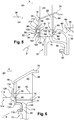
- a the rotating assembly of the turbine is formed by a rotating disc 10 centered on the axis 11 of the turbine, and comprising at its outer periphery teeth (the top of which is referenced 12) arranged alternately with cells (the bottom of which is referenced 14) in which are axially engaged and radially retained blade roots (the inner end of which is referenced 16), these blades 18 extending radially from the cells 14 in an annular stream 20 for the flow of a flow d air (arrow A) from a combustion chamber (not shown).
- each blade 18 comprises radially from the outside towards the inside a blade 22, a platform 24 substantially perpendicular to the axis of elongation 26 of the blade 18 and defining the internal annular limit of the vein d 'flow 20 of the hot gases, a stilt 28 connecting the platform 24 to the blade root 16 having a shape for example of a dovetail or the like to ensure the radial retention of the blade roots 16 in the cells 14.
- spaces are formed between two circumferentially adjacent stilts, and are called inter-stilts or inter-blade cavities 30.
- So-called cell bottom cavities 32 are also formed in the radial spaces separating the blade roots. 16 of the bottom of the cells 14.
- a flow of cooling air B is routed from a low pressure compressor arranged upstream, for example, to the interior of the turbine, and is used on the one hand in order to cool the bottom cavity of the cell 32. and therefore the disc 10, and on the other hand in order to prevent the reintroduction of gases from stream A into the annular space 34 formed between the disc 10 and an upstream stator element 36, this annular space forming a direct communication between the stream 20 of hot gases and internal elements of the turbomachine.
- sealing means are formed upstream and downstream of the disc 10 to define two sealed annular circuits for the circulation of looks like cooling B through the bottom cavities of the cell 32 and in the annular space 34 upstream of the disc 10.
- the objective of these sealing means is to prevent the cooling air B from circulating in the inter-vane cavities 30 through the circumferential spaces formed between the stilts 28, and not to help cool the disc 10 through the bottom cavities of the cell 32, nor to prevent the reintroduction of gases from vein A into the annular space 34 upstream of the disc.
- the sealing means comprise walls 38 extending radially inwardly from upstream of the platforms 24 of the vanes 18 in order to axially and partially close off the inter-vane cavities 30, an annular flange 40 and a ring ring 42.
- the annular flange 40 comprises an internal radial wall 42 for fixing by bolting 44 on a radial annular flange 46 secured to the disc 10 by means of a connecting wall 48. It also comprises a frustoconical wall 50 connecting the internal radial wall 42. to an outer radial annular wall 52 bearing axially downstream on the annular ring 42. Air passage openings 54 are formed at the junction between the inner radial wall 42 of the flange 40 and the annular flange 46 of the disc for allow the circulation of air B between the frustoconical wall 50 of the flange and the connecting wall 48 of the disc 10 to the bottom cavities of the cell 32.
- the annular ring 42 is thus pressed upstream of the blade roots 16 and of the disc 10 radially between the platforms 24 and the cell bottom cavities 32, by means of the radial walls 38 extending from the base. upstream of the platforms 24 and of the radial wall 52 of the flange 40. This assembly is used in order to axially seal the upstream side of the inter-blade cavities 30.
- the downstream sealing means comprise a wiper support ring 56 cooperating with a block of abradable material 60 which is carried by a distributor (not shown), the ring 56 being fixed by bolting 62 between a downstream annular flange 64 of the disc 10 and an upstream annular flange of a downstream disc (not shown),.
- the ring comprises a curved downstream annular arm 66, in elastic axial bearing on an annular ring 68 applied against the downstream faces of the teeth 12 of the disc and of the blade roots 16.
- the ring 68 is arranged radially just above the cavities of the blade. cell bottom 32, so that the cooling air B circulates radially downstream inside the arm 66 of the ring 56.
- Radial walls 70 also extend radially inwards from downstream platforms up to the outer periphery of the annular ring 68, in order to axially seal the inter-blade cavities 30 downstream.
- the flange 40 and the wiper support ring 56 do not apply to the blade roots 16, and on the other hand to the fact that the blade roots 16 expand relatively less than the teeth of the disc.
- the figure 2 shows how an axial gap 72 can be formed between an annular ring 42 and the axial end of a blade root 16, allowing cooling air to flow from the cell bottom cavity towards the inter-vane cavity radially outside the interstice.
- the invention advantageously allows, as shown in the figures 3 and 4 , to form sealing means between the cell bottom cavities 32 and the inter-blade cavities 30, not subject to the relative axial offsets between the ends of the blade roots 16 and the ends of the teeth 12 of the disc 10 due differential expansions between parts and manufacturing tolerances.
- shoulders 74, 76 are arranged circumferentially end to end alternately at the upstream and downstream ends of the blade roots 16 and of the teeth 12 of the disc so as to form an upstream cylindrical surface 78 and a downstream cylindrical surface 78 oriented inwards and on which annular seals 80 are applied.
- These upstream and downstream cylindrical surfaces can be considered as continuous due to the end-to-end arrangement of the shoulders of the blades and of the disc.
- These shoulders are formed radially at the same level as the contact zones between the lateral flanks of the teeth 12 of the disc and the lateral flanks of the blade roots 16, when the blade roots are pressed outwards against the teeth by effect. centrifugal.
- each foot 16 when the feet 16 are in the cells 14, and therefore extend radially to the bottom cavities of the cell 32, the free end 160 of each foot is located radially more inside than its shoulder 74. And each cell bottom 32 is closed and does not communicate with that where the adjacent blade root is housed, unlike what provides GB 2 148 404 where the fact that the free end (68) of each blade root forms the shoulder for the seal (70) causes the receiving space (56) to be circumferential and common to all the feet.
- the solution presented here with individualized teeth and alveoli is preferable.
- each blade comprises a transverse radial wall 84 upstream and a transverse radial wall 84 downstream extending radially between the platform 24 and the blade root 16.
- These transverse radial walls 84 when the blades are formed in CMC , can be made in CMC by weaving or sintering, and assembled by brazing, codensification, siliciding. When the blades are metallic, they can be formed integrally by molding with the upstream and downstream ends of the stilt 28.
- These upstream and downstream transverse walls 84 can also be fixed externally in a similar manner on the platform. 24 dawn shape.
- These walls 84 have at their internal ends a radial finger 88 extending partly over the height of the blade root 16, between projecting parts 90 axially at the external ends of the teeth 12 of the disc.
- the inner end faces 74 of the fingers 88 and the inner faces 76 of the protruding portions 90 of the teeth 12 of the disc form circumferentially aligned cylindrical surface portions 78, facing radially inward, located radially outwardly. cell bottom cavities 32, and having sufficient axial thickness to form the shoulders 74, 76 on which an annular seal 80 can be applied.
- the cylindrical surface portions 74, 76 are therefore aligned circumferentially end to end, which makes it possible to obtain a sealed surface 78 which can be used for fitting a seal.
- the cylindrical surface portions are sized axially large enough so that in operation, despite the relative differences described above between the axial ends of the teeth 12 of the disc and the blade roots 16, there remains a cylindrical surface band 78 where the seal 80 remains in contact so as to ensure a permanent seal.
- the transverse radial walls 84 can be produced, in the case of a CMC blade, by brazing a plate on the axial end face of the blade.
- annular parts are fitted against one of the faces of the disc 10 and of the vanes 18 in order to keep the seal 80 tight against the cylindrical surface 78 of the shoulders 74, 76, and to form the circuit of cooling air passing through the bottom cavities of the cell 32. Thus, there is no longer any leakage from the circuit cooling air to the inter-blade cavities 30.
- the annular part added upstream is a sectored flange 92 comprising an internal part 94 and an external part 96.
- the internal part 94 comprises a cylindrical wall 98 whose part extending away from the disc forms a spoiler, and of which the part close to the disc extending under the shoulders 74, 76 comprises an annular groove 100 in which the annular seal 80 is mounted and pressed against the cylindrical surface 78 of the shoulders.
- the part brought closer to the cylindrical wall is connected to a frustoconical wall 102 extending inwardly, away from the disc and connected at its inner end to a cylindrical rim 104 extending in the direction of the disc 10.
- An annular ring split 106 with a wedge or triangular section is mounted between said frustoconical wall 102 of the flange and the radial faces of the teeth 12 and of the blade roots 16 facing axially the frustoconical wall.
- the cylindrical wall 98 of the flange 92 is also connected to an external part 96 comprising a radial wall 108 extending radially outwardly upstream of clutch members 110 formed at the upstream ends of the projecting parts 90 of the teeth 12 of the disc.
- These clutch members 110 of the teeth of the disc extend upstream from the transverse radial walls 84 upstream of the blades and include L-shaped hooks and hollow parts alternating circumferentially.
- the outer end of the radial wall 108 of the flange 92 includes L-hooks 86 and hollow portions.
- the L-shaped hooks of the flange 92 cooperate with the hooks of the teeth 12 of the disc, to ensure the axial retention of the flange 92 on the disc 10.
- the radial wall 108 is moreover connected externally to a flared flange 112 downstream, intended to come to bear against the transverse radial walls 84 of the blades.
- This assembly makes it possible, thanks to the absorption of the centrifugal forces of the part, to radially crush the seal 80 between the cylindrical wall 98 of the flange and the cylindrical surface 78 formed by the shoulders 74, 76, for optimum sealing.
- the part is mounted by interlocking, once the blades 18 are housed in their cells 14.
- the split ring 106 opens circumferentially in operation by centrifugal effect, and slides between the frustoconical wall 102 and the disc 10, so as to induce tilting of the sectors of the flange 92 around an axis located in the interconnection zone and substantially perpendicular to the axis 11 of the turbine, in order to ensure contact of the free end of the flared rim 112 on the radial walls transverse 84 and thus protect the protruding parts 90 of the disc teeth against the air A of the vein.
- the cooling air circulates between the frustoconical wall 102 and the disc 10, and accesses the bottom cavities of cells 32 then located under the split ring 106.
- the crushing of the seal 80 is ensured by the surface external end of the upstream end of the annular arm 66 of the ring 56, under the effect of centrifugal forces in operation.
- the sealing means according to the invention upstream of the disc can therefore be used in combination with the sealing means downstream of the disc, or else independently of one another. Indeed, optimal sealing does not require forming shoulders upstream and downstream of the disc.
- the annular part added upstream is an annular flange 114 made in one piece.
- the hub 116 of the disc 10 has an axial widening 118 shortly before its outer end.
- the clutch means 110 are formed in this embodiment circumferentially on the upstream face of the hub 116, inside its clutch. enlargement 118.
- the cylindrical wall 116 of the flange 114 extending under the shoulders 74, 76 of the teeth of the disc and of the blade roots, and resting radially against the annular seal 80, is not connected at its end to a frustoconical wall, but to an annular wall 120 extending radially towards the inside of the disc 10 to the clutch means 110 of the hub, and having a shape complementary to that of the disc 10.
- This wall delimits with the part of the disc facing each other. screw an annular cooling air circulation passage B between this wall 120 and the disc.
- This wall also has at its internal end interconnection means 86 cooperating with the interconnecting means 110 of the disc, for axial locking of the flange 114.
- the flange 114 When cold, the flange 114 is mounted prestressed against the annular seal 80 in radial bearing on the cylindrical surface 78 of the shoulders.
- This second embodiment of an upstream flange 114 has the advantage of achieving better sealing of the upstream part of the disc due to its design in one piece, compared to the first embodiment. In addition, it reduces the axial stresses applied to the teeth 12 of the disc 10 due to the positioning of the clutch members at the level of the hub 116.
- the flange 92 of the first embodiment has better mechanical strength, because it is sectorized. , and makes it possible to ensure more reliably the axial contact between the flared rim 112 and the transverse radial walls 84.
Description
L'invention se rapporte à un ensemble rotatif pour turbomachine, telle qu'en particulier un turboréacteur d'avion, ainsi qu'à une turbomachine comprenant un tel ensemble.The invention relates to a rotary assembly for a turbomachine, such as in particular an airplane turbojet, as well as to a turbomachine comprising such an assembly.
Un tel ensemble, que l'on retrouve notamment dans une turbine, comprend un disque, et des aubes s'étendant radialement depuis le disque et dont les pieds sont engagés axialement et retenus radialement dans des alvéoles de la périphérie externe du disque, disposés en alternance avec des dents. Les aubes comprennent également des plates-formes internes agencées circonférentiellement bout à bout de manière à définir ensemble la limite interne du flux d'écoulement des gaz chauds circulant dans la turbine. La partie de l'aube située entre la plate-forme interne et le pied est appelée échasse. Selon cette disposition, des espaces sont formés entre deux échasses adjacentes, et forment des cavités inter-échasses ou inter-aubes. Les plates-formes peuvent se prolonger à leurs extrémités amont et aval par des parois s'étendant radialement vers l'intérieur afin d'obturer axialement et en partie les cavités inter-aubes. Des cavités dites de fond d'alvéole sont également formées dans les espaces radiaux formés entre les pieds d'aubes et les fonds des alvéoles.Such an assembly, which is found in particular in a turbine, comprises a disk, and vanes extending radially from the disk and whose feet are engaged axially and retained radially in cells of the outer periphery of the disk, arranged in alternation with teeth. The blades also include internal platforms arranged circumferentially end to end so as to together define the internal limit of the flow of hot gases circulating in the turbine. The part of the blade located between the internal platform and the foot is called a stilt. According to this arrangement, spaces are formed between two adjacent stilts, and form inter-stilt or inter-blade cavities. The platforms can be extended at their upstream and downstream ends by walls extending radially inwardly in order to axially and partially close off the inter-blade cavities. So-called cell bottom cavities are also formed in the radial spaces formed between the blade roots and the cell bases.
Afin d'assurer le bon fonctionnement de la turbomachine, un air de refroidissement est prélevé dans un compresseur basse-pression ou haute-pression par exemple et acheminé depuis l'amont ou l'aval du disque jusqu'aux cavités de fond d'alvéole afin d'assurer le refroidissement du disque et de protéger ce dernier de l'échauffement provoqué par les gaz chauds du flux de veine circulant entre deux plates-formes adjacentes.In order to ensure the correct operation of the turbomachine, cooling air is taken from a low-pressure or high-pressure compressor for example and routed from upstream or downstream of the disc to the cavities at the bottom of the cell. in order to ensure the cooling of the disc and to protect the latter from the heating caused by the hot gases of the stream flow circulating between two adjacent platforms.
De plus, lorsque l'ensemble rotatif décrit ci-dessus est agencé en amont du rotor de turbine, un espace annulaire est formé entre le disque et un élément de stator amont. Cet espace annulaire forme ainsi une communication directe entre la veine des gaz chauds et des éléments internes de la turbomachine. Dans ce cas, l'air de refroidissement acheminé depuis l'amont du disque sert également à empêcher la réintroduction des gaz de veine dans l'espace annulaire amont du disque.In addition, when the rotary assembly described above is arranged upstream of the turbine rotor, an annular space is formed between the disc and an upstream stator element. This annular space thus forms a direct communication between the hot gas stream and internal elements of the turbomachine. In this case, the cooling air conveyed from the upstream side of the disc also serves to prevent the reintroduction of stream gases into the upstream annular space of the disc.
Dans le cas où aucune technologie particulière d'étanchéité n'est appliquée en amont des cavités inter-aubes et recouvrant par exemple les parois radiales des plates-formes, des fuites d'air de refroidissement se produisent aux zones de jonction entre les aubes et circulent dans les cavités inter-aubes. Ainsi, cet air de refroidissement ne participe pas au refroidissement du disque à travers les cavités de fond d'alvéole, et ne participe pas à empêcher la réintroduction des gaz de veine vers les éléments internes de la turbomachine s'il y a lieu. Ces fuites d'air nécessitent un prélèvement d'air plus important au niveau du compresseur basse-pression, ce qui réduit le rendement de la turbomachine.In the event that no particular sealing technology is applied upstream of the inter-blade cavities and covering, for example, the radial walls of the platforms, cooling air leaks occur at the junction zones between the blades and circulate in the inter-blade cavities. Thus, this cooling air does not participate in the cooling of the disc through the cell bottom cavities, and does not participate in preventing the reintroduction of the flow gases to the internal elements of the turbomachine if necessary. These air leaks require more air to be taken from the low-pressure compressor, which reduces the efficiency of the turbomachine.
Pour minimiser ces fuites d'air, une solution consiste, comme dans
Cependant, il a été remarqué qu'en fonctionnement, l'aube possède un degré de liberté axial dans l'alvéole qui est permis d'une part par le fait que le dimensionnement axial des pieds d'aubes doit être nominalement plus petit que le dimensionnement axial du disque afin de s'assurer que les extrémités des pieds d'aubes ne dépassent jamais des extrémités axiales des alvéoles, pour éviter d'appliquer des contraintes axiales de serrage sur les pieds d'aubes dues par exemple au flasque appliqué sur la face amont du disque. D'autre part, ce degré de liberté est permis par les dilatations différentielles entre le disque et les aubes, en particulier lorsque ces dernières sont formées en Composite à Matrice Céramique (C.M.C.) et que les disques sont réalisés en alliage métallique.However, it has been observed that in operation, the blade has an axial degree of freedom in the cell which is allowed on the one hand by the fact that the axial dimensioning of the blade roots must be nominally smaller than the axial dimensioning of the disk in order to ensure that the ends of the blade roots never protrude from the axial ends of the cells, to avoid applying axial clamping stresses on the blade roots due for example to the flange applied to the upstream face of the disc. On the other hand, this degree of freedom is allowed by the differential expansions between the disc and the blades, in particular when these The latter are made of Ceramic Matrix Composite (CMC) and the discs are made of metal alloy.
En fonctionnement, ce degré de liberté induit donc la formation d'interstices entre le jonc annulaire d'étanchéité serré axialement contre les dents du disque, et les extrémités axiales des pieds des aubes. Une partie de l'air de refroidissement acheminé dans les cavités de fond d'alvéole circule donc à travers ces interstices jusqu'aux cavités inter-aubes et ne remplit plus sa fonction primaire de refroidissement des alvéoles du disque.In operation, this degree of freedom therefore induces the formation of interstices between the annular sealing ring clamped axially against the teeth of the disc, and the axial ends of the root of the blades. Part of the cooling air conveyed into the cell bottom cavities therefore circulates through these interstices to the inter-blade cavities and no longer fulfills its primary function of cooling the cells of the disc.
Dans
La présente invention vise à éviter une telle situation et à sécuriser l'étanchéité,en apportant une solution simple, efficace et économique à ces problèmes.The present invention aims to avoid such a situation and to secure the seal, by providing a simple, effective and economical solution to these problems.
A cette fin, elle propose un ensemble rotatif pour turbomachine, comprenant un disque dont la périphérie externe est formée d'une alternance d'alvéoles et de dents, et des aubes s'étendant radialement depuis le disque et dont les pieds sont engagés axialement et retenus radialement dans les alvéoles du disque, les dents du disque et les pieds d'aube comprenant à leurs extrémités axiales amont et/ou aval des épaulements axiaux disposés circonférentiellement bout à bout en alternance et formant conjointement une surface cylindrique qui fait face radialement vers l'intérieur du disque et sur laquelle est maintenu en appui un joint annulaire d'étanchéité au moyen d'une pièce solidarisée au disque, caractérisé en ce que ladite pièce s'étend sous les épaulements et appuie radialement le joint annulaire contre ladite surface cylindrique .To this end, it proposes a rotary assembly for a turbomachine, comprising a disc whose outer periphery is formed by alternating cells and teeth, and vanes extending radially from the disc and whose feet are axially engaged and retained radially in the cavities of the disc, the teeth of the disc and the blade roots comprising, at their upstream and / or downstream axial ends, axial shoulders arranged circumferentially end to end in alternating and jointly forming a cylindrical surface which faces radially towards the inside of the disc and on which is held in abutment an annular sealing gasket by means of a part secured to the disc, characterized in that said part extends under the shoulders and radially presses the annular seal against said cylindrical surface.
Ainsi, lorsque la pièce annulaire de serrage du joint assure l'amenée d'air comme décrit précédemment, l'air de refroidissement ne peut plus circuler vers une cavité inter-aube du fait du contact continu du joint avec la surface cylindrique formée par les épaulements.Thus, when the annular tightening part of the seal ensures the air supply as described above, the cooling air can no longer circulate towards an inter-vane cavity due to the continuous contact of the seal with the cylindrical surface formed by the shoulders.
De préférence, la pièce de maintien du joint et qui est solidarisée au disque comprendra une gorge annulaire dans laquelle le joint annulaire sera monté. Ainsi, le joint sera bien maintenu et moins sollicité, ceci étant favorable à sa longévité et à son efficacité.Preferably, the part for retaining the seal and which is secured to the disc will comprise an annular groove in which the annular seal will be mounted. Thus, the seal will be well maintained and less stressed, this being favorable to its longevity and its efficiency.
Selon une autre caractéristique de l'invention, les épaulements des pieds d'aubes sont formés par les faces d'extrémités radialement internes de parois radiales amont et/ou aval s'étendant transversalement au pied d'aube et reliées extérieurement à des plates-formes des aubes et intérieurement aux pieds d'aubes (à une certaine distance radiale de l'extrémité libre desquels ces épaulements sont donc situés). Ainsi, le joint annulaire est serré sur une surface cylindrique et non plus sur des surfaces radiales d'extrémités libres des pieds d'aubes. Le joint annulaire reste constamment en contact avec la surface cylindrique quel que soit le déplacement axial relatif entre les pieds d'aubes et les alvéoles du disque en fonctionnement, ce qui permet plus efficacement un serrage sans discontinuité de toute la surface externe du joint sur la surface cylindrique formées par les épaulements axiaux des dents et des pieds d'aubes (la largeur des épaulements des pieds peut être adaptée au besoin, quelle que soit la largeur -ou dimension axiale- des pieds eux-mêmes) .According to another characteristic of the invention, the shoulders of the blade roots are formed by the radially internal end faces of upstream and / or downstream radial walls extending transversely to the blade root and connected externally to platforms. forms of the blades and internally at the blade roots (at a certain radial distance from the free end of which these shoulders are therefore located). Thus, the annular seal is clamped on a cylindrical surface and no longer on the radial surfaces of free ends of the blade roots. The annular seal remains in constant contact with the cylindrical surface regardless of the relative axial displacement between the blade roots and the alveoli of the disk in operation, which more effectively allows seamless clamping of the entire outer surface of the seal on the cylindrical surface formed by the axial shoulders of the teeth and of the blade roots (the width of the root shoulders can be adapted as needed, regardless of the width - or axial dimension - of the feet themselves).
Les parois transverses présentent l'intérêt supplémentaire d'étanchéifier les cavités inter-aubes vis-à-vis du flux de veine.The transverse walls have the additional advantage of sealing the inter-vane cavities with respect to the flow of the vein.
Ladite pièce solidarisée au disque peut être un flasque annulaire appliqué sur une face amont et/ou aval du disque et comprenant des moyens de crabotage coopérant avec des moyens de crabotage complémentaires du disque pour la retenue axiale du flasque sur le disque.Said part secured to the disc may be an annular flange applied to an upstream and / or downstream face of the disc and comprising clutch means cooperating with complementary clutch means of the disc for the axial retention of the flange on the disc.
Préférentiellement, le flasque est formé de plusieurs secteurs agencés circonférentiellement bout à bout et chaque secteur de flasque comprend une partie interne en appui radialement vers l'extérieur sur le joint annulaire et une partie externe comprenant lesdits moyens de crabotage coopérant avec lesdits moyens de crabotage complémentaires formés sur les dents du disque, ces moyens de crabotage complémentaires du disque étant formés en saillie axiale par rapport aux pieds d'aubes.Preferably, the flange is formed of several sectors arranged circumferentially end to end and each flange sector comprises an internal part bearing radially outwardly on the annular seal and an external part comprising said clutch means cooperating with said complementary clutch means. formed on the teeth of the disc, these complementary clutch means of the disc being formed in axial projection with respect to the blade roots.
Avantageusement, la partie externe de chaque secteur de flasque comprend une paroi radiale se prolongeant extérieurement par un rebord évasé dont l'extrémité libre externe est destinée à venir en appui sur l'une des parois transverses amont ou aval des aubes.Advantageously, the outer part of each flange sector comprises a radial wall extending outwardly by a flared rim, the outer free end of which is intended to bear on one of the upstream or downstream transverse walls of the blades.
Pour un effet optimal, la partie interne de chaque secteur de flasque comprend une paroi cylindrique dont une partie d'extrémité en vis-à-vis du disque est en appui radialement vers l'extérieur sur le joint annulaire et se prolonge par une paroi tronconique s'étendant vers l'intérieur en s'éloignant du disque, un jonc annulaire fendu étant intercalé axialement entre la paroi tronconique et le disque.For an optimal effect, the internal part of each flange sector comprises a cylindrical wall, an end part of which facing the disc bears radially outwards on the annular seal and is extended by a frustoconical wall. extending inwardly away from the disc, a split annular ring being interposed axially between the frustoconical wall and the disc.
Ce montage avec un unique appui radial de la paroi cylindrique au niveau du joint permet, grâce à la reprise des efforts centrifuges de la pièce, d'écraser le joint entre la paroi cylindrique du flasque et la surface cylindrique formée par les épaulements pour une étanchéité optimale. A froid, la pièce est montée par crabotage, une fois les aubes logées dans leurs alvéoles. En fonctionnement, la force centrifuge induit une augmentation du diamètre du jonc lequel appuie sur la paroi tronconique et provoque un basculement axial des secteurs du flasque autour de la ligne de crabotage, ce qui amène l'extrémité libre du rebord évasé à venir en contact avec les parois radiales transverses des aubes, évite ainsi une réintroduction d'air de veine entre les rebords évasés et les parois radiales transverses et assure une meilleure protection thermique des dents.This assembly with a single radial support of the cylindrical wall at the level of the seal makes it possible, thanks to the absorption of the centrifugal forces of the part, to crush the seal between the cylindrical wall of the flange and the cylindrical surface formed by the shoulders for a seal. optimal. When cold, the part is assembled by interlocking, once the blades are housed in their cells. In operation, the centrifugal force induces an increase in the diameter of the ring which presses on the frustoconical wall and causes an axial tilting of the sectors of the flange around the clutch line, which brings the free end of the flared rim to come into contact with the transverse radial walls of the blades, thus avoiding reintroduction of flow air between the flared edges and the radial walls transverse and provides better thermal protection of the teeth.
Selon une autre réalisation de l'invention, ladite pièce solidarisée au disque est un anneau de support de léchettes d'étanchéité destinées à coopérer avec un bloc de matière abradable en vis-à-vis radial.According to another embodiment of the invention, said part secured to the disc is a support ring for sealing wipers intended to cooperate with a block of abradable material facing radially.
Avantageusement, l'aube est en composite à matrice céramique et le disque est en alliage métallique permettant une réduction significative de la masse (le rapport de densité entre alliage métallique et C.M.C. étant compris entre 3 et 4) du rotor permettant une réduction de la consommation de la turbomachine.Advantageously, the blade is made of a ceramic matrix composite and the disk is made of a metal alloy allowing a significant reduction in the mass (the density ratio between metal alloy and CMC being between 3 and 4) of the rotor allowing a reduction in consumption. of the turbomachine.
L'invention concerne également une turbine de turbomachine, caractérisée en ce qu'elle comprend un ensemble rotatif selon l'une des revendications précédentes.The invention also relates to a turbomachine turbine, characterized in that it comprises a rotary assembly according to one of the preceding claims.
L'invention concerne enfin une turbomachine, telle qu'un turboréacteur ou un turbopropulseur, caractérisée en ce qu'elle comprend un ensemble rotatif selon l'une des revendications précédentes.The invention finally relates to a turbomachine, such as a turbojet or a turboprop, characterized in that it comprises a rotary assembly according to one of the preceding claims.
D'autres avantages et caractéristiques de l'invention apparaîtront à la lecture de la description suivante faite à titre d'exemple non limitatif et en référence aux dessins annexés dans lesquels :
- la
figure 1 est une vue schématique en coupe axiale d'un ensemble rotatif de turbine selon l'art antérieur ; - la
figure 2 est une vue schématique selon le plan de coupe II-II de lafigure 1 ; - la
figure 3 est une vue en perspective d'un ensemble rotatif selon l'invention, vue de l'amont ou de l'aval suivant la réalisation retenue ; - la
figure 4 est une vue schématique de même type que lafigure 2 et selon l'invention ; - la
figure 5 est une vue schématique en coupe axiale d'un ensemble rotatif de turbine selon une première réalisation de l'invention ; - la
figure 6 est une vue schématique en coupe axiale d'un ensemble rotatif de turbine selon une seconde réalisation de l'invention.
- the
figure 1 is a schematic view in axial section of a rotary turbine assembly according to the prior art; - the
figure 2 is a schematic view along section II-II of thefigure 1 ; - the
figure 3 is a perspective view of a rotary assembly according to the invention, seen from upstream or downstream depending on the embodiment selected; - the
figure 4 is a schematic view of the same type as thefigure 2 and according to the invention; - the
figure 5 is a schematic view in axial section of a rotary turbine assembly according to a first embodiment of the invention; - the
figure 6 is a schematic view in axial section of a rotary turbine assembly according to a second embodiment of the invention.
Selon la technique connue représentée en
Plus particulièrement, chaque aube 18 comprend radialement depuis l'extérieur vers l'intérieur une pale 22, une plate-forme 24 sensiblement perpendiculaire à l'axe d'allongement 26 de l'aube 18 et définissant la limite annulaire interne de la veine d'écoulement 20 des gaz chauds, une échasse 28 reliant la plate-forme 24 au pied d'aube 16 ayant une forme par exemple en queue d'aronde ou analogue pour assurer la retenue radiale des pieds d'aubes 16 dans les alvéoles 14. Selon cette disposition, des espaces sont formés entre deux échasses circonférentiellement adjacentes, et sont appelés des cavités inter-échasses ou inter-aubes 30. Des cavités dites de fond d'alvéole 32 sont également formées dans les espaces radiaux séparant les pieds d'aubes 16 des fonds des alvéoles 14.More particularly, each
Un débit d'air de refroidissement B est acheminé depuis un compresseur basse pression agencé en amont, par exemple, jusqu'à l'intérieur de la turbine, et est utilisé d'une part afin de refroidir la cavité de fond d'alvéole 32 et donc le disque 10, et d'autre part afin d'empêcher la réintroduction des gaz de veine A dans l'espace annulaire 34 formé entre le disque 10 et un élément de stator amont 36, cet espace annulaire formant une communication directe entre la veine 20 des gaz chauds et des éléments internes de la turbomachine.A flow of cooling air B is routed from a low pressure compressor arranged upstream, for example, to the interior of the turbine, and is used on the one hand in order to cool the bottom cavity of the
Pour limiter le prélèvement d'air de refroidissement issu du compresseur, ce qui nuit aux performances de la turbomachine, des moyens d'étanchéité sont formés à l'amont et à l'aval du disque 10 pour définir deux circuits annulaires étanches de circulation de l'air de refroidissement B à travers les cavités de fond d'alvéole 32 et dans l'espace annulaire 34 en amont du disque 10. En particulier, l'objectif de ces moyens d'étanchéité est d'empêcher l'air de refroidissement B de circuler dans les cavités inter-aubes 30 à travers les espaces circonférentiels formés entre les échasses 28, et de ne contribuer ni à refroidir le disque 10 à travers les cavités de fond d'alvéole 32, ni à empêcher la réintroduction des gaz de veine A dans l'espace annulaire 34 en amont du disque.To limit the intake of cooling air from the compressor, which is detrimental to the performance of the turbomachine, sealing means are formed upstream and downstream of the
Les moyens d'étanchéité comprennent des parois 38 s'étendant radialement vers l'intérieur depuis l'amont des plates-formes 24 des aubes 18 afin d'obturer axialement et en partie les cavités inter-aubes 30, un flasque annulaire 40 et un jonc annulaire 42.The sealing means
Le flasque annulaire 40 comprend une paroi radiale interne 42 de fixation par boulonnage 44 sur une bride annulaire radiale 46 solidarisée au disque 10 par l'intermédiaire d'une paroi de liaison 48. Il comprend également une paroi tronconique 50 reliant la paroi radiale interne 42 à une paroi annulaire radiale externe 52 en appui axialement vers l'aval sur le jonc annulaire 42. Des ouvertures 54 de passage d'air sont ménagées à la jonction entre la paroi radiale interne 42 du flasque 40 et la bride annulaire 46 du disque pour permettre la circulation d'air B entre la paroi tronconique 50 du flasque et la paroi de liaison 48 du disque 10 jusqu'aux cavités de fond d'alvéole 32.The
Le jonc annulaire 42 est ainsi plaqué à l'amont des pieds d'aubes 16 et du disque 10 radialement entre les plates-formes 24 et les cavités de fond d'alvéole 32, au moyen des parois radiales 38 s'étendant depuis l'amont des plates-formes 24 et de la paroi radiale 52 du flasque 40. Cet ensemble est utilisé afin d'étanchéifier axialement l'amont des cavités inter-aubes 30.The
Les moyens d'étanchéité aval comprennent un anneau 56 de support de léchettes 58 coopérant avec un bloc de matière abradable 60 qui est porté par un distributeur (non représenté), l'anneau 56 étant fixé par boulonnage 62 entre une bride annulaire aval 64 du disque 10 et une bride annulaire amont d'un disque aval (non représenté), . L'anneau comprend un bras annulaire 66 aval incurvé, en appui axial élastique sur un jonc annulaire 68 appliqué contre les faces aval des dents 12 du disque et des pieds d'aubes 16. Le jonc 68 est agencé radialement juste au dessus des cavités de fond d'alvéole 32, afin que l'air de refroidissement B circule vers l'aval radialement à l'intérieur du bras 66 de l'anneau 56. Des parois radiales 70 s'étendent également radialement vers l'intérieur depuis l'aval des plates-formes jusqu'à la périphérie externe du jonc annulaire 68, afin d'étanchéifier axialement à l'aval les cavités inter-aubes 30.The downstream sealing means comprise a
Selon ce montage, il a été remarqué qu'en fonctionnement, une partie de l'air de refroidissement B passe des cavités de fond d'alvéole 32 vers les cavités inter-aubes 30. En effet, en fonctionnement, alors que les joncs annulaires 42, 68 sont plaqués contre les surfaces radiales d'extrémité des dents 12 du disque, des interstices 72 axiaux se forment entre les joncs annulaires 42, 68 et les extrémités axiales des pieds d'aubes 16. Cela est du d'une part au fait que le dimensionnement axial du pied d'aube 16 est nominalement plus petit que le dimensionnement axial du disque 10 afin de s'assurer que les extrémités des pieds d'aubes ne dépassent jamais des alvéoles 14 pour éviter que les contraintes axiales de serrage du flasque 40 et de l'anneau 56 de support de léchettes ne s'appliquent aux pieds d'aubes 16, et d'autre part au fait que les pieds d'aubes 16 se dilatent relativement moins que les dents du disque. Notamment, pour des aubes 18 en composite à matrice céramique (C.M.C.) et un disque 10 réalisé en alliage métallique par exemple à base Nickel résistant à haute température et apte à être forgé, il existe un rapport de deux à trois entre les dilatations différentielles de ces pièces. A cet égard, la
L'invention permet avantageusement, comme le montrent les
Selon l'invention, des épaulements 74, 76 sont agencés circonférentiellement bout à bout en alternance aux extrémités amont et aval des pieds d'aube 16 et des dents 12 du disque de manière à former une surface cylindrique 78 amont et une surface cylindrique 78 aval orientées vers l'intérieur et sur lesquelles des joints annulaires 80 sont appliquées. Ces surfaces cylindriques amont et aval peuvent être considérées comme continues du fait de l'agencement bout à bout des épaulements des aubes et du disque. Ces épaulements sont formés radialement au même niveau que les zones de contact entre les flancs latéraux des dents 12 du disque et les flancs latéraux des pieds d'aubes 16, lorsque les pieds d'aubes sont plaqués vers l'extérieur contre les dents par effet centrifuge. Comme on le voit
Pour cela, chaque aube comprend une paroi radiale transverse 84 amont et une paroi radiale transverse 84 aval s'étendant radialement entre la plate-forme 24 et le pied d'aube 16. Ces parois radiales transverses 84, lorsque les aubes sont formées en C.M.C., peuvent être réalisées en C.M.C. par tissage ou frittage, et assemblées par brasage, codensification, siliciuration. Lorsque les aubes sont métalliques, elles peuvent être formées d'une seule pièce par moulage avec les extrémités amont et aval de l'échasse 28. Ces parois transverses amont et aval 84 peuvent également être fixées extérieurement d'une manière similaire sur la plate-forme 24 de l'aube. Ces parois 84 possèdent à leurs extrémités internes un doigt radial 88 s'étendant en partie sur la hauteur du pied d'aube 16, entre des parties en saillie 90 axiale aux extrémités externes des dents 12 du disque. Les faces d'extrémité internes 74 des doigts 88 et les faces internes 76 des parties en saillie 90 des dents 12 du disque forment des portions de surface cylindrique 78 alignées circonférentiellement, faisant face radialement vers l'intérieur, situées radialement à l'extérieur des cavités de fond d'alvéole 32, et possédant une épaisseur axiale suffisante pour former les épaulements 74, 76 sur lequel un joint annulaire 80 peut être appliqué.For this, each blade comprises a transverse
Ces portions 74, 76 de surface sont donc alignées circonférentiellement bout à bout, ce qui permet d'obtenir une surface 78 étanche utilisable pour la pose d'un joint d'étanchéité. Les portions de surface cylindrique sont dimensionnées assez grandes axialement pour qu'en fonctionnement, malgré les écarts relatifs décrits plus haut entre les extrémités axiales des dents 12 du disque et des pieds d'aube 16, il subsiste une bande de surface cylindrique 78 où le joint 80 reste en contact de manière à assurer une étanchéité permanente. Les parois radiales transverses 84 peuvent être réalisées, dans le cas d'une aube en CMC, par brasage d'une plaquette sur la face d'extrémité axiale de l'aube.These
L'invention décrite ci-dessus est mise en œuvre dans deux modes de réalisation, le premier étant représenté à la
Dans le premier mode de réalisation représenté en
La paroi cylindrique 98 du flasque 92 est également reliée à une partie externe 96 comprenant une paroi radiale 108 s'étendant radialement vers l'extérieur en amont d'organes de crabotage 110 formés aux extrémités amont des parties en saillie 90 des dents 12 du disque. Ces organes de crabotage 110 des dents du disque s'étendent en saillie vers l'amont par rapport aux parois radiales transverses 84 amont des aubes et comprennent des crochets en L et des parties creuses alternées circonférentiellement. L'extrémité externe de la paroi radiale 108 du flasque 92 comprend des crochets en L 86 et des parties creuses. Les crochets en L du flasque 92 coopèrent avec les crochets des dents 12 du disque, pour assurer la retenue axiale du flasque 92 sur le disque 10. La paroi radiale 108 est de plus reliée extérieurement à un rebord évasé 112 vers l'aval, destiné à venir en appui contre les parois radiales transverses 84 des aubes.The
Ce montage permet, grâce à la reprise des efforts centrifuges de la pièce, d'écraser radialement le joint 80 entre la paroi cylindrique 98 du flasque et la surface cylindrique 78 formée par les épaulements 74, 76, pour une étanchéité optimale. A froid, la pièce est montée par crabotage, une fois les aubes 18 logées dans leurs alvéoles 14. Le jonc fendu 106 s'ouvre circonférentiellement en fonctionnement par effet centrifuge, et glisse entre la paroi tronconique 102 et le disque 10, de manière à induire un basculement des secteurs du flasque 92 autour d'un axe situé dans la zone de crabotage et sensiblement perpendiculaire à l'axe 11 de la turbine, afin d'assurer un contact de l'extrémité libre du rebord évasé 112 sur les parois radiales transverses 84 et ainsi protéger les parties en saillie 90 des dents de disque contre l'air A de veine.This assembly makes it possible, thanks to the absorption of the centrifugal forces of the part, to radially crush the
En fonctionnement, l'air de refroidissement circule entre la paroi tronconique 102 et le disque 10, et accède aux cavités de fond d'alvéoles 32 se situant alors sous le jonc fendu 106.In operation, the cooling air circulates between the
A l'aval du disque, et dans le cas où le circuit de refroidissement ne se limite pas seulement au fond d'alvéole mais aussi au refroidissement d'un anneau 56 supportant des léchettes, l'écrasement du joint 80 est assuré par la surface externe de l'extrémité amont du bras annulaire 66 de l'anneau 56, sous l'effet des forces centrifuges en fonctionnement.Downstream of the disc, and in the case where the cooling circuit is not limited only to the cell bottom but also to the cooling of a
Les moyens d'étanchéité selon l'invention en amont du disque peuvent donc être utilisés en combinaison avec les moyens d'étanchéité à l'aval du disque, ou bien de manière indépendante les uns des autres. En effet, une étanchéité optimale ne nécessite pas de former des épaulements à l'amont et à l'aval du disque.The sealing means according to the invention upstream of the disc can therefore be used in combination with the sealing means downstream of the disc, or else independently of one another. Indeed, optimal sealing does not require forming shoulders upstream and downstream of the disc.
Dans le second mode de réalisation représenté en
Contrairement au premier mode de réalisation, la paroi cylindrique 116 du flasque 114, s'étendant sous les épaulements 74, 76 des dents du disque et des pieds d'aube, et s'appuyant radialement contre le joint annulaire 80, n'est pas reliée à son extrémité à une paroi tronconique, mais à une paroi annulaire 120 s'étendant radialement vers l'intérieur du disque 10 jusqu'aux moyens de crabotage 110 du moyeu, et ayant une forme complémentaire de celle du disque 10. Cette paroi délimite avec la partie du disque en vis-à-vis un passage annulaire de circulation de l'air de refroidissement B entre cette paroi 120 et le disque. Cette paroi possède en outre à son extrémité interne des moyens de crabotage 86 coopérant avec les moyens de crabotage 110 du disque, pour un blocage axial du flasque 114.Unlike the first embodiment, the
A froid, le flasque 114 est monté précontraint contre le joint annulaire 80 en appui radial sur la surface cylindrique 78 des épaulements.When cold, the
Ce second mode de réalisation d'un flasque amont 114 a l'avantage de réaliser une meilleure étanchéité de la partie amont du disque du fait de sa conception en une seule pièce, par rapport au premier mode de réalisation. De plus, il réduit les contraintes axiales appliquées aux dents 12 du disque 10 du fait du positionnement des organes de crabotage au niveau du moyeu 116. En revanche, le flasque 92 du premier mode de réalisation possède une meilleure tenue mécanique, car il est sectorisé, et permet d'assurer de manière plus fiable le contact axial entre le rebord évasé 112 et les parois radiales transverses 84.This second embodiment of an
Claims (13)
- A rotary assembly for a turbomachine, the rotary assembly comprising:- a disk (10) the outer periphery of which is formed from an alternation of cavities (14) and teeth (12),- blades (18) extending radially from the disk (10) and roots (16) of which are axially engaged into, and radially held in the cavities (14) of the disk, and,- a cylindrical surface (78) facing radially towards the inside of the disk and on which an annular seal (80) is maintained by means of a part (56, 92, 114) solidarized to the disk, said part (56, 92, 114) extending under the shoulders (74, 76) and radially pressing the annular seal (80) against said cylindrical surface (78),characterized in that the teeth (12) of the disk and the blade roots (16) comprise, at upstream and/or downstream axial ends thereof, said axial shoulders (74, 76) which are disposed circumferentially end-to-end in alternation and which together form said cylindrical surface (78).
- The rotary assembly according to claim 1, characterized in that said part (56, 92, 114) comprises an annular groove (100) wherein the annular seal (80) is mounted.
- The assembly according to claim 1 or 2, characterized in that the shoulders (74) of the blade roots (16) are formed by radially inner end faces of upstream and/or downstream radial walls (84) which extend transversely to the blade root and are externally connected to platforms (24) of the blades and internally to the blade roots (16).
- The assembly according to one of the preceding claims characterized:- in that said part solidarized to the disk is an annular flange (92, 114) applied onto an upstream and/or downstream face of the disk and comprising jaw clutching means (86) cooperating with matching jaw clutching means (110) of the disk (10) for axially holding the flange on the disk, and the flange (92) is formed of several sectors arranged circumferentially end-to-end and,- in that each flange section comprises an inner portion (94) radially supported toward the outside by the annular seal (80) and an outer portion (96) comprising said jaw clutching means (86) cooperating said matching jaw clutching means (110) formed on the teeth (12) of the disk, said matching jaw clutching means of the disk axially protruding with respect to the blade roots (16).
- The assembly according to claim 4 when dependent on claim 3, characterized in that the outer portion (96) of each flange section (92) comprises a radial wall (108) extending externally in a flared rim (112), the outer free end of which is intended to rest applied on one of the upstream or downstream transverse walls (84) of the blades.
- The assembly according to claim 4 or 5, characterized in that the inner portion (94) of each flange section (92) comprises a cylindrical wall (98), one end portion of which facing the disk is radially applied toward the outside on the annular seal (80) and is extended by a frustoconical wall (102) extending inwardly away from the disk (10), with a split annular ring (106) being axially inserted between the frustoconical wall (102) and the disk (10).
- The assembly according to claim 3, characterized in that said part made integral with the disk is a ring (56) for supporting sealing lips (58) intended to cooperate with a radially opposite block (60) made of an abradable material.
- The assembly according to one of the preceding claims, characterized in that the blade (18) is made of a ceramic matrix composite material and the disk (10) is made of a metal alloy.
- The assembly according to one of the preceding claims, characterized in that the cylindrical surface (78) which faces radially towards the inside of the disk and on which the annular seal (80) is applied is free of annular groove wherein an annular seal would be mounted.
- The assembly according to one of the preceding claims, characterized in that each cavity (14) has a bottom and each cavity bottom is closed, so that said cavity bottom has no communication with the cavity bottom in which is disposed an adjacent blade root.
- The assembly according to one of the preceding claims, characterized in that the shoulders (74,76) are radially formed at the same level than contact zones between lateral flanks of the disc teeth (12) and lateral flanks of the blade roots (16), when the blade roots are pressed outwards against the teeth by centrifugal effect.
- A turbine for a turbomachine, characterized in that it comprises the rotary assembly according to one of the preceding claims.
- A turbomachine such as a turbojet or a turboprop, characterized in that it comprises the rotary assembly according to one of claims 1 to 11.
Applications Claiming Priority (2)
| Application Number | Priority Date | Filing Date | Title |
|---|---|---|---|
| FR1359239A FR3011032B1 (en) | 2013-09-25 | 2013-09-25 | ROTARY ASSEMBLY FOR TURBOMACHINE |
| PCT/FR2014/052375 WO2015044578A1 (en) | 2013-09-25 | 2014-09-23 | Rotary assembly for a turbomachine |
Publications (2)
| Publication Number | Publication Date |
|---|---|
| EP3049636A1 EP3049636A1 (en) | 2016-08-03 |
| EP3049636B1 true EP3049636B1 (en) | 2021-11-10 |
Family
ID=50424337
Family Applications (1)
| Application Number | Title | Priority Date | Filing Date |
|---|---|---|---|
| EP14790196.1A Active EP3049636B1 (en) | 2013-09-25 | 2014-09-23 | Rotary assembly for a turbomachine |
Country Status (9)
| Country | Link |
|---|---|
| US (1) | US10662795B2 (en) |
| EP (1) | EP3049636B1 (en) |
| JP (1) | JP6457500B2 (en) |
| CN (1) | CN105658912B (en) |
| BR (1) | BR112016006597B1 (en) |
| CA (1) | CA2925438C (en) |
| FR (1) | FR3011032B1 (en) |
| RU (1) | RU2676497C2 (en) |
| WO (1) | WO2015044578A1 (en) |
Families Citing this family (8)
| Publication number | Priority date | Publication date | Assignee | Title |
|---|---|---|---|---|
| FR3022944B1 (en) * | 2014-06-26 | 2020-02-14 | Safran Aircraft Engines | ROTARY ASSEMBLY FOR TURBOMACHINE |
| JP6613611B2 (en) | 2015-05-15 | 2019-12-04 | 株式会社Ihi | Turbine blade mounting structure |
| FR3073581B1 (en) * | 2017-11-14 | 2019-11-22 | Safran Aircraft Engines | DEVICE FOR MAINTAINING A CENTRAL RADIAL RADIAL AIR COLLECTION DEVICE |
| FR3086701B1 (en) * | 2018-09-28 | 2021-01-01 | Safran Aircraft Engines | WATERPROOFING OF DAWN FOOT |
| US10704400B2 (en) * | 2018-10-17 | 2020-07-07 | Pratt & Whitney Canada Corp. | Rotor assembly with rotor disc lip |
| FR3091554B1 (en) | 2019-01-03 | 2022-08-12 | Safran Aircraft Engines | BLADE FOR A TURBOMACHINE ROTOR |
| KR102127429B1 (en) * | 2019-06-05 | 2020-06-26 | 두산중공업 주식회사 | Sealing structure between turbine rotor disk and interstage disk |
| FR3112366B1 (en) * | 2020-07-10 | 2022-07-22 | Safran Aircraft Engines | Wedge for retaining a turbomachine retaining ring |
Family Cites Families (23)
| Publication number | Priority date | Publication date | Assignee | Title |
|---|---|---|---|---|
| US60276A (en) * | 1866-12-04 | Impeoted steeefflg appaeatits | ||
| BE794573A (en) * | 1972-02-02 | 1973-05-16 | Gen Electric | AUBES FIXING DEVICE |
| US3853425A (en) * | 1973-09-07 | 1974-12-10 | Westinghouse Electric Corp | Turbine rotor blade cooling and sealing system |
| US4218189A (en) * | 1977-08-09 | 1980-08-19 | Rolls-Royce Limited | Sealing means for bladed rotor for a gas turbine engine |
| FR2524932A1 (en) * | 1982-04-08 | 1983-10-14 | Snecma | DEVICE FOR AXIAL RETENTION OF BLADE FEET IN A TURBOMACHINE DISC |
| US4523890A (en) * | 1983-10-19 | 1985-06-18 | General Motors Corporation | End seal for turbine blade base |
| US5318405A (en) * | 1993-03-17 | 1994-06-07 | General Electric Company | Turbine disk interstage seal anti-rotation key through disk dovetail slot |
| GB2332024B (en) * | 1997-12-03 | 2000-12-13 | Rolls Royce Plc | Rotary assembly |
| US6234756B1 (en) * | 1998-10-26 | 2001-05-22 | Allison Advanced Development Company | Segmented ring blade retainer |
| US6464453B2 (en) | 2000-12-04 | 2002-10-15 | General Electric Company | Turbine interstage sealing ring |
| GB0302116D0 (en) * | 2003-01-30 | 2003-03-05 | Rolls Royce Plc | A rotor |
| FR2867223B1 (en) | 2004-03-03 | 2006-07-28 | Snecma Moteurs | TURBOMACHINE AS FOR EXAMPLE A TURBOJET AIRCRAFT |
| US7238008B2 (en) * | 2004-05-28 | 2007-07-03 | General Electric Company | Turbine blade retainer seal |
| US20060275108A1 (en) * | 2005-06-07 | 2006-12-07 | Memmen Robert L | Hammerhead fluid seal |
| EP2239419A1 (en) * | 2009-03-31 | 2010-10-13 | Siemens Aktiengesellschaft | Axial turbo engine rotor with sealing disc |
| US8007230B2 (en) * | 2010-01-05 | 2011-08-30 | General Electric Company | Turbine seal plate assembly |
| US8727730B2 (en) * | 2010-04-06 | 2014-05-20 | General Electric Company | Composite turbine bucket assembly |
| FR2960589B1 (en) * | 2010-05-28 | 2014-05-02 | Snecma | WHEEL A BLADE FOR A TURBOMACHINE, SUCH AS A TURBOJET OR AIRCRAFT TURBOPROPULSER |
| FR2978793B1 (en) * | 2011-08-03 | 2015-12-04 | Snecma | ROTOR OF TURBINE FOR A TURBOMACHINE |
| FR2982635B1 (en) * | 2011-11-15 | 2013-11-15 | Snecma | AUBES WHEEL FOR A TURBOMACHINE |
| US9004874B2 (en) | 2012-02-22 | 2015-04-14 | General Electric Company | Interlaminar stress reducing configuration for composite turbine components |
| WO2014028593A1 (en) * | 2012-08-15 | 2014-02-20 | Bell Geospace Inc. | Directional filter for processing full tensor gradiometer data |
| JP5358031B1 (en) * | 2013-03-22 | 2013-12-04 | 三菱重工業株式会社 | Turbine rotor, turbine, and seal plate removal method |
-
2013
- 2013-09-25 FR FR1359239A patent/FR3011032B1/en active Active
-
2014
- 2014-09-23 WO PCT/FR2014/052375 patent/WO2015044578A1/en active Application Filing
- 2014-09-23 EP EP14790196.1A patent/EP3049636B1/en active Active
- 2014-09-23 JP JP2016516849A patent/JP6457500B2/en active Active
- 2014-09-23 US US15/024,752 patent/US10662795B2/en active Active
- 2014-09-23 CN CN201480057417.XA patent/CN105658912B/en active Active
- 2014-09-23 CA CA2925438A patent/CA2925438C/en active Active
- 2014-09-23 BR BR112016006597-2A patent/BR112016006597B1/en active IP Right Grant
- 2014-09-23 RU RU2016110757A patent/RU2676497C2/en active
Non-Patent Citations (1)
| Title |
|---|
| None * |
Also Published As
| Publication number | Publication date |
|---|---|
| FR3011032A1 (en) | 2015-03-27 |
| RU2016110757A3 (en) | 2018-06-09 |
| EP3049636A1 (en) | 2016-08-03 |
| BR112016006597A2 (en) | 2017-08-01 |
| RU2676497C2 (en) | 2018-12-29 |
| CN105658912B (en) | 2018-03-13 |
| JP6457500B2 (en) | 2019-01-23 |
| CA2925438C (en) | 2021-09-28 |
| BR112016006597B1 (en) | 2022-05-03 |
| JP2016535827A (en) | 2016-11-17 |
| US10662795B2 (en) | 2020-05-26 |
| US20160237840A1 (en) | 2016-08-18 |
| WO2015044578A1 (en) | 2015-04-02 |
| CA2925438A1 (en) | 2015-04-02 |
| FR3011032B1 (en) | 2017-12-29 |
| RU2016110757A (en) | 2017-10-30 |
| CN105658912A (en) | 2016-06-08 |
Similar Documents
| Publication | Publication Date | Title |
|---|---|---|
| EP3049636B1 (en) | Rotary assembly for a turbomachine | |
| EP3523507B1 (en) | Movable ring assembly for a turbine engine turbine | |
| EP2504529B1 (en) | Insulation of a circumferential edge of an outer casing of a turbine engine from a corresponding ring sector | |
| FR3072720A1 (en) | CARTRIDGE FOR TURBOMACHINE COMPRISING A CENTRAL PORTION PROJECTED IN RELATION TO TWO SIDE PORTIONS IN A JUNCTION REGION | |
| EP1975374B1 (en) | External casing for a turbomachine turbine wheel | |
| EP3049637B1 (en) | Rotary assembly for turbomachine | |
| EP3161263B1 (en) | Drehbare vorrichtung einer turbomaschine | |
| EP2252773A2 (en) | Stator assembly for a turbomachine | |
| FR2922589A1 (en) | CONTROL OF THE AUBES SET IN A HIGH-PRESSURE TURBINE TURBINE | |
| EP2582920A1 (en) | Angular stator sector for a turbomachine compressor, turbomachine stator and turbomachine comprising such a sector | |
| FR3020408A1 (en) | ROTARY ASSEMBLY FOR TURBOMACHINE | |
| WO2013001240A1 (en) | Labyrinth seal for gas turbine engine turbine | |
| FR2919345A1 (en) | Cylindrical or truncated ring for e.g. jet prop engine, has internal slots housing internal blades between discharge ends of channels and internal longitudinal edges of radial surfaces, where blades extend on axial length of ring sectors | |
| FR2923528A1 (en) | TURBINE OR COMPRESSOR STAGE OF A TURBOREACTOR | |
| FR2961848A1 (en) | TURBINE FLOOR | |
| EP3874131B1 (en) | Turbine shroud sector with cooled sealing strips | |
| WO2015185860A1 (en) | Rotor for turbine engine comprising blades with added platforms | |
| FR3092609A1 (en) | TURBINE ASSEMBLY FOR AIRCRAFT TURBOMACHINE WITH IMPROVED DISC COOLING CIRCUIT | |
| FR2961556A1 (en) | Turbine i.e. low pressure turbine, for e.g. turbojet engine of airplane, has axial and radial support units that are not in contact with casing to avoid heating, by conduction, of casing by sectorized ring during operation | |
| FR3049307A1 (en) | ROTARY ASSEMBLY FOR TURBOMACHINE | |
| FR3086328A1 (en) | TURBINE WITH BLADES HELD AXIALLY, FOR TURBOMACHINE | |
| FR3111964A1 (en) | Assembly of a combustion chamber part by overlapping another part |
Legal Events
| Date | Code | Title | Description |
|---|---|---|---|
| PUAI | Public reference made under article 153(3) epc to a published international application that has entered the european phase |
Free format text: ORIGINAL CODE: 0009012 |
|
| 17P | Request for examination filed |
Effective date: 20160414 |
|
| AK | Designated contracting states |
Kind code of ref document: A1 Designated state(s): AL AT BE BG CH CY CZ DE DK EE ES FI FR GB GR HR HU IE IS IT LI LT LU LV MC MK MT NL NO PL PT RO RS SE SI SK SM TR |
|
| AX | Request for extension of the european patent |
Extension state: BA ME |
|
| DAX | Request for extension of the european patent (deleted) | ||
| RAP1 | Party data changed (applicant data changed or rights of an application transferred) |
Owner name: SAFRAN AIRCRAFT ENGINES |
|
| GRAP | Despatch of communication of intention to grant a patent |
Free format text: ORIGINAL CODE: EPIDOSNIGR1 |
|
| STAA | Information on the status of an ep patent application or granted ep patent |
Free format text: STATUS: GRANT OF PATENT IS INTENDED |
|
| INTG | Intention to grant announced |
Effective date: 20201211 |
|
| RIN1 | Information on inventor provided before grant (corrected) |
Inventor name: ROUSSILLE, CLEMENT Inventor name: CARLOS, PIERRE-LOUIS, ALEXANDRE Inventor name: LEDUC, MATHIEU, LOUIS, JEAN |
|
| GRAJ | Information related to disapproval of communication of intention to grant by the applicant or resumption of examination proceedings by the epo deleted |
Free format text: ORIGINAL CODE: EPIDOSDIGR1 |
|
| STAA | Information on the status of an ep patent application or granted ep patent |
Free format text: STATUS: REQUEST FOR EXAMINATION WAS MADE |
|
| INTC | Intention to grant announced (deleted) | ||
| GRAS | Grant fee paid |
Free format text: ORIGINAL CODE: EPIDOSNIGR3 |
|
| STAA | Information on the status of an ep patent application or granted ep patent |
Free format text: STATUS: GRANT OF PATENT IS INTENDED |
|
| GRAP | Despatch of communication of intention to grant a patent |
Free format text: ORIGINAL CODE: EPIDOSNIGR1 |
|
| INTG | Intention to grant announced |
Effective date: 20210604 |
|
| GRAA | (expected) grant |
Free format text: ORIGINAL CODE: 0009210 |
|
| STAA | Information on the status of an ep patent application or granted ep patent |
Free format text: STATUS: THE PATENT HAS BEEN GRANTED |
|
| AK | Designated contracting states |
Kind code of ref document: B1 Designated state(s): AL AT BE BG CH CY CZ DE DK EE ES FI FR GB GR HR HU IE IS IT LI LT LU LV MC MK MT NL NO PL PT RO RS SE SI SK SM TR |
|
| REG | Reference to a national code |
Ref country code: GB Ref legal event code: FG4D Free format text: NOT ENGLISH |
|
| REG | Reference to a national code |
Ref country code: AT Ref legal event code: REF Ref document number: 1446291 Country of ref document: AT Kind code of ref document: T Effective date: 20211115 Ref country code: CH Ref legal event code: EP |
|
| REG | Reference to a national code |
Ref country code: DE Ref legal event code: R096 Ref document number: 602014081188 Country of ref document: DE |
|
| REG | Reference to a national code |
Ref country code: IE Ref legal event code: FG4D Free format text: LANGUAGE OF EP DOCUMENT: FRENCH |
|
| REG | Reference to a national code |
Ref country code: SE Ref legal event code: TRGR |
|
| REG | Reference to a national code |
Ref country code: LT Ref legal event code: MG9D |
|
| REG | Reference to a national code |
Ref country code: NL Ref legal event code: MP Effective date: 20211110 |
|
| REG | Reference to a national code |
Ref country code: AT Ref legal event code: MK05 Ref document number: 1446291 Country of ref document: AT Kind code of ref document: T Effective date: 20211110 |
|
| PG25 | Lapsed in a contracting state [announced via postgrant information from national office to epo] |
Ref country code: RS Free format text: LAPSE BECAUSE OF FAILURE TO SUBMIT A TRANSLATION OF THE DESCRIPTION OR TO PAY THE FEE WITHIN THE PRESCRIBED TIME-LIMIT Effective date: 20211110 Ref country code: LT Free format text: LAPSE BECAUSE OF FAILURE TO SUBMIT A TRANSLATION OF THE DESCRIPTION OR TO PAY THE FEE WITHIN THE PRESCRIBED TIME-LIMIT Effective date: 20211110 Ref country code: FI Free format text: LAPSE BECAUSE OF FAILURE TO SUBMIT A TRANSLATION OF THE DESCRIPTION OR TO PAY THE FEE WITHIN THE PRESCRIBED TIME-LIMIT Effective date: 20211110 Ref country code: BG Free format text: LAPSE BECAUSE OF FAILURE TO SUBMIT A TRANSLATION OF THE DESCRIPTION OR TO PAY THE FEE WITHIN THE PRESCRIBED TIME-LIMIT Effective date: 20220210 Ref country code: AT Free format text: LAPSE BECAUSE OF FAILURE TO SUBMIT A TRANSLATION OF THE DESCRIPTION OR TO PAY THE FEE WITHIN THE PRESCRIBED TIME-LIMIT Effective date: 20211110 |
|
| PG25 | Lapsed in a contracting state [announced via postgrant information from national office to epo] |
Ref country code: IS Free format text: LAPSE BECAUSE OF FAILURE TO SUBMIT A TRANSLATION OF THE DESCRIPTION OR TO PAY THE FEE WITHIN THE PRESCRIBED TIME-LIMIT Effective date: 20220310 Ref country code: PT Free format text: LAPSE BECAUSE OF FAILURE TO SUBMIT A TRANSLATION OF THE DESCRIPTION OR TO PAY THE FEE WITHIN THE PRESCRIBED TIME-LIMIT Effective date: 20220310 Ref country code: PL Free format text: LAPSE BECAUSE OF FAILURE TO SUBMIT A TRANSLATION OF THE DESCRIPTION OR TO PAY THE FEE WITHIN THE PRESCRIBED TIME-LIMIT Effective date: 20211110 Ref country code: NO Free format text: LAPSE BECAUSE OF FAILURE TO SUBMIT A TRANSLATION OF THE DESCRIPTION OR TO PAY THE FEE WITHIN THE PRESCRIBED TIME-LIMIT Effective date: 20220210 Ref country code: NL Free format text: LAPSE BECAUSE OF FAILURE TO SUBMIT A TRANSLATION OF THE DESCRIPTION OR TO PAY THE FEE WITHIN THE PRESCRIBED TIME-LIMIT Effective date: 20211110 Ref country code: LV Free format text: LAPSE BECAUSE OF FAILURE TO SUBMIT A TRANSLATION OF THE DESCRIPTION OR TO PAY THE FEE WITHIN THE PRESCRIBED TIME-LIMIT Effective date: 20211110 Ref country code: HR Free format text: LAPSE BECAUSE OF FAILURE TO SUBMIT A TRANSLATION OF THE DESCRIPTION OR TO PAY THE FEE WITHIN THE PRESCRIBED TIME-LIMIT Effective date: 20211110 Ref country code: GR Free format text: LAPSE BECAUSE OF FAILURE TO SUBMIT A TRANSLATION OF THE DESCRIPTION OR TO PAY THE FEE WITHIN THE PRESCRIBED TIME-LIMIT Effective date: 20220211 Ref country code: ES Free format text: LAPSE BECAUSE OF FAILURE TO SUBMIT A TRANSLATION OF THE DESCRIPTION OR TO PAY THE FEE WITHIN THE PRESCRIBED TIME-LIMIT Effective date: 20211110 |
|
| PG25 | Lapsed in a contracting state [announced via postgrant information from national office to epo] |
Ref country code: SM Free format text: LAPSE BECAUSE OF FAILURE TO SUBMIT A TRANSLATION OF THE DESCRIPTION OR TO PAY THE FEE WITHIN THE PRESCRIBED TIME-LIMIT Effective date: 20211110 Ref country code: SK Free format text: LAPSE BECAUSE OF FAILURE TO SUBMIT A TRANSLATION OF THE DESCRIPTION OR TO PAY THE FEE WITHIN THE PRESCRIBED TIME-LIMIT Effective date: 20211110 Ref country code: RO Free format text: LAPSE BECAUSE OF FAILURE TO SUBMIT A TRANSLATION OF THE DESCRIPTION OR TO PAY THE FEE WITHIN THE PRESCRIBED TIME-LIMIT Effective date: 20211110 Ref country code: EE Free format text: LAPSE BECAUSE OF FAILURE TO SUBMIT A TRANSLATION OF THE DESCRIPTION OR TO PAY THE FEE WITHIN THE PRESCRIBED TIME-LIMIT Effective date: 20211110 Ref country code: DK Free format text: LAPSE BECAUSE OF FAILURE TO SUBMIT A TRANSLATION OF THE DESCRIPTION OR TO PAY THE FEE WITHIN THE PRESCRIBED TIME-LIMIT Effective date: 20211110 Ref country code: CZ Free format text: LAPSE BECAUSE OF FAILURE TO SUBMIT A TRANSLATION OF THE DESCRIPTION OR TO PAY THE FEE WITHIN THE PRESCRIBED TIME-LIMIT Effective date: 20211110 |
|
| REG | Reference to a national code |
Ref country code: DE Ref legal event code: R097 Ref document number: 602014081188 Country of ref document: DE |
|
| PLBE | No opposition filed within time limit |
Free format text: ORIGINAL CODE: 0009261 |
|
| STAA | Information on the status of an ep patent application or granted ep patent |
Free format text: STATUS: NO OPPOSITION FILED WITHIN TIME LIMIT |
|
| 26N | No opposition filed |
Effective date: 20220811 |
|
| PG25 | Lapsed in a contracting state [announced via postgrant information from national office to epo] |
Ref country code: AL Free format text: LAPSE BECAUSE OF FAILURE TO SUBMIT A TRANSLATION OF THE DESCRIPTION OR TO PAY THE FEE WITHIN THE PRESCRIBED TIME-LIMIT Effective date: 20211110 |
|
| PG25 | Lapsed in a contracting state [announced via postgrant information from national office to epo] |
Ref country code: SI Free format text: LAPSE BECAUSE OF FAILURE TO SUBMIT A TRANSLATION OF THE DESCRIPTION OR TO PAY THE FEE WITHIN THE PRESCRIBED TIME-LIMIT Effective date: 20211110 |
|
| PG25 | Lapsed in a contracting state [announced via postgrant information from national office to epo] |
Ref country code: MC Free format text: LAPSE BECAUSE OF FAILURE TO SUBMIT A TRANSLATION OF THE DESCRIPTION OR TO PAY THE FEE WITHIN THE PRESCRIBED TIME-LIMIT Effective date: 20211110 |
|
| REG | Reference to a national code |
Ref country code: CH Ref legal event code: PL |
|
| REG | Reference to a national code |
Ref country code: BE Ref legal event code: MM Effective date: 20220930 |
|
| PG25 | Lapsed in a contracting state [announced via postgrant information from national office to epo] |
Ref country code: LU Free format text: LAPSE BECAUSE OF NON-PAYMENT OF DUE FEES Effective date: 20220923 |
|
| PG25 | Lapsed in a contracting state [announced via postgrant information from national office to epo] |
Ref country code: LI Free format text: LAPSE BECAUSE OF NON-PAYMENT OF DUE FEES Effective date: 20220930 Ref country code: IE Free format text: LAPSE BECAUSE OF NON-PAYMENT OF DUE FEES Effective date: 20220923 Ref country code: CH Free format text: LAPSE BECAUSE OF NON-PAYMENT OF DUE FEES Effective date: 20220930 |
|
| PG25 | Lapsed in a contracting state [announced via postgrant information from national office to epo] |
Ref country code: BE Free format text: LAPSE BECAUSE OF NON-PAYMENT OF DUE FEES Effective date: 20220930 |
|
| PGFP | Annual fee paid to national office [announced via postgrant information from national office to epo] |
Ref country code: IT Payment date: 20230822 Year of fee payment: 10 Ref country code: GB Payment date: 20230823 Year of fee payment: 10 |
|
| PGFP | Annual fee paid to national office [announced via postgrant information from national office to epo] |
Ref country code: SE Payment date: 20230822 Year of fee payment: 10 Ref country code: FR Payment date: 20230822 Year of fee payment: 10 Ref country code: DE Payment date: 20230822 Year of fee payment: 10 |
|
| PG25 | Lapsed in a contracting state [announced via postgrant information from national office to epo] |
Ref country code: HU Free format text: LAPSE BECAUSE OF FAILURE TO SUBMIT A TRANSLATION OF THE DESCRIPTION OR TO PAY THE FEE WITHIN THE PRESCRIBED TIME-LIMIT; INVALID AB INITIO Effective date: 20140923 |
|
| PG25 | Lapsed in a contracting state [announced via postgrant information from national office to epo] |
Ref country code: CY Free format text: LAPSE BECAUSE OF FAILURE TO SUBMIT A TRANSLATION OF THE DESCRIPTION OR TO PAY THE FEE WITHIN THE PRESCRIBED TIME-LIMIT Effective date: 20211110 |