EP3523507B1 - Movable ring assembly for a turbine engine turbine - Google Patents
Movable ring assembly for a turbine engine turbine Download PDFInfo
- Publication number
- EP3523507B1 EP3523507B1 EP17786988.0A EP17786988A EP3523507B1 EP 3523507 B1 EP3523507 B1 EP 3523507B1 EP 17786988 A EP17786988 A EP 17786988A EP 3523507 B1 EP3523507 B1 EP 3523507B1
- Authority
- EP
- European Patent Office
- Prior art keywords
- movable ring
- ferrule
- ring assembly
- upstream
- assembly
- Prior art date
- Legal status (The legal status is an assumption and is not a legal conclusion. Google has not performed a legal analysis and makes no representation as to the accuracy of the status listed.)
- Active
Links
- 238000011144 upstream manufacturing Methods 0.000 claims description 46
- 238000007789 sealing Methods 0.000 claims description 5
- 238000012423 maintenance Methods 0.000 description 5
- 230000035882 stress Effects 0.000 description 4
- 230000000295 complement effect Effects 0.000 description 3
- 238000001816 cooling Methods 0.000 description 2
- 238000009792 diffusion process Methods 0.000 description 2
- 238000009423 ventilation Methods 0.000 description 2
- 230000000903 blocking effect Effects 0.000 description 1
- 238000010438 heat treatment Methods 0.000 description 1
- 230000014759 maintenance of location Effects 0.000 description 1
- 238000000034 method Methods 0.000 description 1
- 210000003456 pulmonary alveoli Anatomy 0.000 description 1
- 230000008646 thermal stress Effects 0.000 description 1
Images


Classifications
-
- F—MECHANICAL ENGINEERING; LIGHTING; HEATING; WEAPONS; BLASTING
- F01—MACHINES OR ENGINES IN GENERAL; ENGINE PLANTS IN GENERAL; STEAM ENGINES
- F01D—NON-POSITIVE DISPLACEMENT MACHINES OR ENGINES, e.g. STEAM TURBINES
- F01D5/00—Blades; Blade-carrying members; Heating, heat-insulating, cooling or antivibration means on the blades or the members
- F01D5/02—Blade-carrying members, e.g. rotors
- F01D5/06—Rotors for more than one axial stage, e.g. of drum or multiple disc type; Details thereof, e.g. shafts, shaft connections
- F01D5/066—Connecting means for joining rotor-discs or rotor-elements together, e.g. by a central bolt, by clamps
-
- F—MECHANICAL ENGINEERING; LIGHTING; HEATING; WEAPONS; BLASTING
- F01—MACHINES OR ENGINES IN GENERAL; ENGINE PLANTS IN GENERAL; STEAM ENGINES
- F01D—NON-POSITIVE DISPLACEMENT MACHINES OR ENGINES, e.g. STEAM TURBINES
- F01D11/00—Preventing or minimising internal leakage of working-fluid, e.g. between stages
- F01D11/001—Preventing or minimising internal leakage of working-fluid, e.g. between stages for sealing space between stator blade and rotor
-
- F—MECHANICAL ENGINEERING; LIGHTING; HEATING; WEAPONS; BLASTING
- F01—MACHINES OR ENGINES IN GENERAL; ENGINE PLANTS IN GENERAL; STEAM ENGINES
- F01D—NON-POSITIVE DISPLACEMENT MACHINES OR ENGINES, e.g. STEAM TURBINES
- F01D11/00—Preventing or minimising internal leakage of working-fluid, e.g. between stages
- F01D11/005—Sealing means between non relatively rotating elements
- F01D11/006—Sealing the gap between rotor blades or blades and rotor
- F01D11/008—Sealing the gap between rotor blades or blades and rotor by spacer elements between the blades, e.g. independent interblade platforms
-
- F—MECHANICAL ENGINEERING; LIGHTING; HEATING; WEAPONS; BLASTING
- F01—MACHINES OR ENGINES IN GENERAL; ENGINE PLANTS IN GENERAL; STEAM ENGINES
- F01D—NON-POSITIVE DISPLACEMENT MACHINES OR ENGINES, e.g. STEAM TURBINES
- F01D11/00—Preventing or minimising internal leakage of working-fluid, e.g. between stages
- F01D11/02—Preventing or minimising internal leakage of working-fluid, e.g. between stages by non-contact sealings, e.g. of labyrinth type
-
- F—MECHANICAL ENGINEERING; LIGHTING; HEATING; WEAPONS; BLASTING
- F01—MACHINES OR ENGINES IN GENERAL; ENGINE PLANTS IN GENERAL; STEAM ENGINES
- F01D—NON-POSITIVE DISPLACEMENT MACHINES OR ENGINES, e.g. STEAM TURBINES
- F01D5/00—Blades; Blade-carrying members; Heating, heat-insulating, cooling or antivibration means on the blades or the members
- F01D5/30—Fixing blades to rotors; Blade roots ; Blade spacers
- F01D5/3007—Fixing blades to rotors; Blade roots ; Blade spacers of axial insertion type
- F01D5/3015—Fixing blades to rotors; Blade roots ; Blade spacers of axial insertion type with side plates
-
- F—MECHANICAL ENGINEERING; LIGHTING; HEATING; WEAPONS; BLASTING
- F01—MACHINES OR ENGINES IN GENERAL; ENGINE PLANTS IN GENERAL; STEAM ENGINES
- F01D—NON-POSITIVE DISPLACEMENT MACHINES OR ENGINES, e.g. STEAM TURBINES
- F01D5/00—Blades; Blade-carrying members; Heating, heat-insulating, cooling or antivibration means on the blades or the members
- F01D5/30—Fixing blades to rotors; Blade roots ; Blade spacers
- F01D5/3069—Fixing blades to rotors; Blade roots ; Blade spacers between two discs or rings
-
- F—MECHANICAL ENGINEERING; LIGHTING; HEATING; WEAPONS; BLASTING
- F05—INDEXING SCHEMES RELATING TO ENGINES OR PUMPS IN VARIOUS SUBCLASSES OF CLASSES F01-F04
- F05D—INDEXING SCHEME FOR ASPECTS RELATING TO NON-POSITIVE-DISPLACEMENT MACHINES OR ENGINES, GAS-TURBINES OR JET-PROPULSION PLANTS
- F05D2260/00—Function
- F05D2260/30—Retaining components in desired mutual position
- F05D2260/31—Retaining bolts or nuts
Definitions
- the invention relates to a movable ring assembly for a turbomachine turbine.
- the figure 1 shows an example of a turbine part of a turbomachine known from the state of the art.
- the turbine 10 consists of a distributor formed by a plurality of fixed vanes 12 arranged in a flow stream 14 and a movable wheel placed behind the distributor and formed by a plurality of movable vanes 16 also arranged in the flow stream 14 and mounted by their foot in cells 18 of rotor discs 20a, 20b, 20c, 20d, 20e.
- the rotor discs of the turbine 20a, 20b, 20c, 20d, 20e are centered on the longitudinal axis XX and are generally assembled together by means of upstream 22 and downstream ferrules 24 which are fixed to each other by bolted connections 26 passing through fixing flanges 221 and 241. This disc assembly is itself connected to a turbine shaft (not shown) to be driven in rotation.
- a movable ring 28 carrying radial wipers 32 is disposed at the junction between each successive rotor disc, facing the corresponding fixed vane 12.
- Certain movable rings 28 can also include an upstream flange 31 ensuring the maintenance of a retaining ring 27 bearing against the bladed disc (20a, 20b) upstream of the movable ring.
- each movable ring 28 cooperates with the internal annular surface of the fixed vane 12 opposite said ring 28 and thus ensure the seal between the upstream cavity and the downstream cavity of the turbine.
- the outer annular portion of the movable ring 28 is subjected to very high temperatures due to the hot air flow stream 14. This results in a strong thermal gradient between the outer annular portion of the rings 28 and their internal annular portion. This gradient leads to strong constraints at the level fixing flanges 221 and 241. It leads to the phenomenon known as “flange opening” which reduces the service life of the rotor discs of a turbomachine turbine.
- One of the aims of the invention is to increase the service life of turbomachine turbines by limiting the phenomenon of flange opening at the junction between successive rotor disks.
- Another object of the invention is to allow better mechanical strength of the junction flanges of the successive rotor discs of a turbomachine turbine subjected to high thermal stresses.
- Another object of the invention is to provide cooling of the connecting cells between the rotor discs and the turbine blades.
- Another object of the invention is to seal between the upstream and downstream cavities of the turbine.
- Another object of the invention is to ensure the retention of retaining rings at the junction between blade and rotor disc.
- Another object of the invention is to simplify the maintenance of turbomachine turbines.
- the invention also relates to a turbomachine, comprising an assembly according to the preceding description.
- the proposed solution for assembling the movable ring of a turbomachine turbine makes it possible to dissociate the external annular portion of movable rings from the bolted connection so that the movable ring is no longer exposed to the temperature gradient.
- Disc flanges are subject to greatly reduced stresses and their service life is significantly increased.
- the proposed solution makes it possible to retain the initial functions of the movable rings. Indeed, the seal between the upstream cavity and the downstream cavity is ensured by means of the wipers. In addition, ventilation of the bottom of the alveolus of the downstream disc is always permitted thanks to the lunulae formed in the internal annular portion of the ferrules. Finally, the downstream retaining flange is always in abutment against the junction between the disc and the downstream vane, and, if it is present, the upstream retaining flange maintains the retaining ring in abutment against the bladed upstream disc.
- This assembly 4 is disposed between an upstream rotor disc 20a and a downstream rotor disc 20b and connected to these via a bolted connection 26.
- the bolted connection 26 engages a fixing flange 442 of the ferrule 44, a fixing flange 241 of a downstream ferrule 24 extending from an external annular portion of the upstream disc 20a, and a fixing flange 221 an upstream ferrule 22 extending from an external annular portion of the downstream disc 20b.
- This assembly seals between the upstream cavity and the downstream cavity, allows ventilation of the downstream rotor disc 20b and maintains a retaining ring 27 in abutment against the upstream bladed disc 20a.
- the movable ring 42 is a part of revolution around an axis XX of the turbomachine. It comprises a downstream annular flange 30 bearing against a cell 18 of the bladed downstream rotor disc 20b.
- the external and internal annular surfaces of this flange have been referenced by 301 and 302.
- the end 303 of the flange 30, bearing against the cavity 18, may further comprise an annular groove 304 configured to receive an annular seal 305.
- annular seal 305 can be made of DMD0415 (HS25).
- the space 60 is particularly useful for ventilating the downstream disc 20b, as will be described more precisely below.
- Radial sealing wipers 32 extend from the external surface 301. They are configured to cooperate in operation with an internal surface 120 of an annular hub carrying the stationary vanes 12 of the distributor in order to seal between the upstream cavity and the downstream cavity located on either side of the hub carrying the fixed vanes 12.
- the movable ring 42 may further comprise an upstream annular flange 31 which extends from a flange 420 of the movable ring 42. This upstream annular flange bears against the retaining ring 27 in order to maintain it against the upstream bladed disc 20a.
- the retaining ring 27 has the function of axially retaining the moving blades 16.
- the movable ring 42 is hooped, at its base, on the downstream ferrule 24 of the upstream rotor disc 20a.
- connection between the movable ring 42 and the upstream rotor disc 20a can also be used for anti-rotation of the different parts of the assembly 4 relative to each other.
- the movable ring 42 comprises an annular flange called anti-rotation 50 extending radially inwards from the internal radial annular surface 302 of the ring, and having a series of grooves 52 extending Radially inward, periodically all around the flange 50.
- anti-rotation 50 extending radially inwards from the internal radial annular surface 302 of the ring, and having a series of grooves 52 extending Radially inward, periodically all around the flange 50.
- the function of the flange 50 and the grooves 52 will be detailed later.
- the ferrule 44 comprises on its upstream surface (surface 440) a circumferential groove 45 configured to receive the annular seal 46.
- This seal 46 is compressed between the flange 420 of the movable ring 42 and the ferrule 44 by the bolted connection 26.
- the seal 46 ensures the continuity of the seal between the upstream and downstream cavities of the turbine.
- the seal 46 since the seal 46 is located at the interface between two parts at very different temperatures, it is now up to it to be subjected to a strong thermal gradient. Consequently, the seal 46 can be made of DMD0415 (HS25).
- the ferrule 44 also has, on the downstream side (surface 441) one or more cooling rings 43 arranged above the bolted connection 26, for example a series of circumferential rings 43 regularly distributed at a portion of downstream tangential surface 441.
- These lunules 43 allow a circulation of fresh air taken upstream of the turbine and circulating through each bolted connection 26. This fresh air circulating from upstream of the turbine is able to pass through the lunule 43 to the cavity of air diffusion 60 before diffusing into each cell 18 of the disc 20b to ventilate them.
- the fixing ferrule 44 ends, below said lunula 43 by a fixing flange 442 which is configured to allow the fixing of the ferrule 44 in the bolted connection 26.
- the flange 442 has a series of openings distributed periodically and intended to come opposite a series of similar openings made respectively in the flanges 241 and 221 of the downstream ferrules 24 of the upstream disc 20a and upstream 22 of the downstream disc 20b.
- the ferrule 44 may comprise a series of anti-rotation studs 54 which project in relation to the rest of said ferrule 44. These studs are periodically spaced all around the ferrule 44 so as to be opposite grooves 52 that has the flange 50 of the movable ring 42 ( figures 4a and 4b ).
- the grooves 52 and tenons 54 are configured to cooperate with each other all around the ring 42 and the ferrule 44 respectively. They therefore have substantially complementary forms.
- the tenon-groove system described above can ensure the centering of the ring 42 in the assembly 4 in the event of loss of the hooping of the ring 42.
- the rotation can be stopped by a system of tenon-grooves made at the interface between the movable ring 42 and the downstream ferrule 24 of the upstream disc 20a.
- the annular flange 50 is hooped on the external annular portion of the ferrule 44.
- the assembly 4 further comprises a retaining stop 41 configured to ensure the stability of the movable ring 42 in operation, in particular in the event of loss of the hooping of the ring 42.
- the assembly 4 is subjected to stresses important centrifugals due to the rotation of the moving wheel. It is therefore essential to guarantee the mechanical consistency of the assembly 4, whatever the operating conditions.
- the retaining stop 41 may take the form of a hook 410 formed by the lower end of the ring 42, and extending upstream so as to cooperate with a bore 412, of shape complementary to that of the hook 410, and formed in the downstream end of the downstream ferrule 24.
- the hook 410 cooperates with a bore 412 formed in the upstream portion 440 of the ferrule 44, for example under the circumferential groove 45 receiving the seal 46.
- the hook 410 is formed by the upper end of the ferrule 44, and also extends upstream so as to cooperate with a bore 412, of shape complementary to that of the hook 410, and formed in the downstream portion of the collar 420 of the ring 42.
- the shape and dimensions of the hook 410 and of the bore 412 can vary depending on the intensity of the desired maintenance, but also on considerations of ease of assembly, for example for maintenance. It is thus possible to dimension the bore 412 slightly larger than the hook 410, so as to leave an operating margin before the abutment 41 comes into contact so as not to immediately pull on the flange 442.
- the hook 410 can advantageously be hooped in the bore 412, so as to favor the maintenance offered by the stop 41.
- the retaining stop 41 may also include several hooks 410 formed on the ring 42 or the ferrule 44, and cooperating with several corresponding bores 412.
- the hook 410 and the bore 412 can be formed in revolution around the longitudinal axis X-X, or be formed only on successive angular portions, equally distributed or not, around the longitudinal axis X-X.
- the assembly 4 is made more robust, in particular in the event of loss of hooping of the movable ring 42.
- the proposed assembly therefore allows an increase in the life of a turbomachine turbine by reducing the phenomenon of flange opening at the bolted connections which connect the various turbine rotor discs.
Description
L'invention concerne un assemblage d'anneau mobile de turbine de turbomachine.The invention relates to a movable ring assembly for a turbomachine turbine.
La
La turbine 10 se compose d'un distributeur formé d'une pluralité d'aubes fixes 12 disposées dans une veine d'écoulement 14 et d'une roue mobile placée derrière le distributeur et formée d'une pluralité d'aubes mobiles 16 également disposées dans la veine d'écoulement 14 et montées par leur pied dans des alvéoles 18 de disques de rotor 20a, 20b, 20c, 20d, 20e.The
Les disques de rotor de la turbine 20a, 20b, 20c, 20d, 20e sont centrés sur l'axe longitudinal X-X et sont généralement assemblés entre eux au moyen de viroles amont 22 et aval 24 qui sont fixées entre elles par des liaisons boulonnées 26 traversant des brides de fixation 221 et 241. Cet assemblage de disques est lui-même relié à un arbre de turbine (non représenté) pour être entraîné en rotation.The rotor discs of the
De plus, un anneau mobile 28 porteur de léchettes radiales 32 est disposé à la jonction entre chaque disque de rotor successif, en regard de l'aube fixe 12 correspondante.In addition, a
Il est fixé dans la liaison boulonnée 26 et comprend une bride de maintien aval 30 venant en appui contre l'alvéole 18.It is fixed in the bolted
Certains anneaux mobiles 28 peuvent également comprendre une bride amont 31 assurant le maintien d'un anneau de retenue 27 en appui contre le disque aubagé (20a, 20b) en amont de l'anneau mobile.Certain
Les léchettes radiales 32 de chaque anneau mobile 28 coopèrent avec la surface annulaire interne de l'aube fixe 12 en regard dudit anneau 28 et assurent ainsi, l'étanchéité entre la cavité amont et la cavité aval de la turbine.The
Or, la portion annulaire externe de l'anneau mobile 28 est soumise à des températures très importantes du fait de la veine d'écoulement d'air chaud 14. Il en résulte un fort gradient thermique entre la portion annulaire externe des anneaux 28 et leur portion annulaire interne. Ce gradient entraine de fortes contraintes au niveau des brides de fixation 221 et 241. Il conduit au phénomène dit « d'ouverture des brides » qui réduit la durée de vie des disques rotor de turbine de turbomachine.However, the outer annular portion of the
Ce phénomène est plus particulièrement illustré sur la
Un des buts de l'invention est d'augmenter la durée de vie des turbines de turbomachine en limitant le phénomène d'ouverture de brides au niveau de la jonction entre les disques de rotor successifs.One of the aims of the invention is to increase the service life of turbomachine turbines by limiting the phenomenon of flange opening at the junction between successive rotor disks.
Un autre but de l'invention est de permettre une meilleure tenue mécanique des brides de jonction des disques de rotor successifs de turbine de turbomachine soumises à de fortes contraintes thermiques.Another object of the invention is to allow better mechanical strength of the junction flanges of the successive rotor discs of a turbomachine turbine subjected to high thermal stresses.
Un autre but de l'invention est d'assurer le refroidissement des alvéoles de jonction entre les disques de rotor et les aubes de turbine.Another object of the invention is to provide cooling of the connecting cells between the rotor discs and the turbine blades.
Un autre but de l'invention est d'assurer l'étanchéité entre les cavités amont et aval de la turbine.Another object of the invention is to seal between the upstream and downstream cavities of the turbine.
Un autre but de l'invention est d'assurer le maintien d'anneaux de retenue au niveau de la jonction entre aube et disque de rotor.Another object of the invention is to ensure the retention of retaining rings at the junction between blade and rotor disc.
Un autre but de l'invention est de simplifier la maintenance des turbines de turbomachine.Another object of the invention is to simplify the maintenance of turbomachine turbines.
A cet égard, l'invention a pour objet un assemblage d'anneau mobile de turbine de turbomachine qui est monté entre deux disques de rotor et successifs de ladite turbine, lesdits disques de rotor et étant fixés l'un sur l'autre par boulonnage, caractérisé en ce qu'il comprend :
- une virole de fixation fixée entre les disques amont et aval, par le boulonnage de ceux-ci, et
- une pièce formant anneau mobile, ladite pièce portant des léchettes radiales d'étanchéité et étant fixée entre le disque amont et la virole.
- a fixing ferrule fixed between the upstream and downstream discs, by the bolting thereof, and
- a part forming a movable ring, said part carrying radial sealing wipers and being fixed between the upstream disc and the ferrule.
Avantageusement, mais facultativement, l'assemblage d'anneau mobile selon l'invention peut en outre comprendre au moins l'une des caractéristiques suivantes :
- il comprend en outre un joint d'étanchéité interposé entre la pièce formant anneau mobile et la virole,
- l'anneau mobile est fretté sur le disque amont,
- la virole comprend au moins une lunule au-dessus de la liaison boulonnée,
- la virole comprend plusieurs lunules réparties de manière périodique au niveau d'une portion de surface tangentielle aval de la virole,
- l'assemblage d'anneau mobile comporte un ensemble de rainures et de tenons assurant l'anti-rotation de l'anneau mobile par rapport à la virole,
- les rainures sont disposées dans l'anneau mobile et les tenons s'étendent depuis la virole,
- lequel les rainures de l'anneau mobile sont disposées dans une bride d'anti-rotation s'étendant à partir d'une surface annulaire interne de l'anneau mobile, et réparties de manière périodique sur une zone annulaire de ladite bride éloignée de la surface annulaire interne de l'anneau mobile,
- les tenons sont répartis de manière périodique et régulière sur une surface annulaire externe de la virole, en regard des rainures correspondantes de la bride d'anti-rotation de l'anneau mobile,
- l'anneau mobile comprend en outre une bride annulaire amont s'étendant à partir d'une portion de surface tangentielle amont de l'anneau mobile et maintenant un anneau de retenue en appui contre le disque aubagé amont
- il comprend en outre une butée de maintien de l'anneau mobile, ladite butée comprenant un crochet coopérant avec un alésage,
- le crochet est formé sur l'anneau mobile et l'alésage est ménagé dans la virole, et
- le crochet est formé sur la virole et l'alésage est ménagé dans l'anneau mobile.
- it further comprises a seal interposed between the part forming a movable ring and the ferrule,
- the movable ring is hooped on the upstream disc,
- the ferrule comprises at least one lunula above the bolted connection,
- the shell includes several lunules distributed periodically at a portion of the tangential surface downstream of the shell,
- the movable ring assembly comprises a set of grooves and tenons ensuring the anti-rotation of the movable ring relative to the ferrule,
- the grooves are arranged in the movable ring and the pins extend from the ferrule,
- wherein the grooves of the movable ring are arranged in an anti-rotation flange extending from an internal annular surface of the movable ring, and distributed periodically over an annular zone of said flange remote from the internal annular surface of the movable ring,
- the pins are distributed periodically and regularly over an external annular surface of the shell, opposite the corresponding grooves of the anti-rotation flange of the movable ring,
- the movable ring further comprises an upstream annular flange extending from a portion of upstream tangential surface of the movable ring and maintaining a retaining ring in abutment against the upstream bladed disc
- it further comprises a stop for holding the movable ring, said stop comprising a hook cooperating with a bore,
- the hook is formed on the movable ring and the bore is formed in the ferrule, and
- the hook is formed on the ferrule and the bore is formed in the movable ring.
L'invention a également pour objet une turbomachine, comprenant un assemblage selon la description qui précède.The invention also relates to a turbomachine, comprising an assembly according to the preceding description.
La solution proposée d'assemblage d'anneau mobile de turbine de turbomachine permet de dissocier la portion annulaire externe d'anneaux mobiles de la liaison boulonnée de sorte à ce que l'anneau mobile ne soit plus exposé au gradient de température. Les brides de disques subissent des contraintes fortement diminuées et leur durée de vie est significativement augmentée.The proposed solution for assembling the movable ring of a turbomachine turbine makes it possible to dissociate the external annular portion of movable rings from the bolted connection so that the movable ring is no longer exposed to the temperature gradient. Disc flanges are subject to greatly reduced stresses and their service life is significantly increased.
En outre, la solution proposée permet de conserver les fonctions initiales des anneaux mobiles. En effet, l'étanchéité entre la cavité amont et la cavité aval est assurée grâce aux léchettes. De plus, la ventilation du fond d'alvéole du disque aval est toujours permise grâce aux lunules pratiquées dans la portion annulaire interne des viroles. Enfin, la bride de maintien aval est toujours en appui contre la jonction entre le disque et l'aube aval, et, si elle est présente, la bride de maintien amont maintient l'anneau de retenue en appuie contre le disque amont aubagé.In addition, the proposed solution makes it possible to retain the initial functions of the movable rings. Indeed, the seal between the upstream cavity and the downstream cavity is ensured by means of the wipers. In addition, ventilation of the bottom of the alveolus of the downstream disc is always permitted thanks to the lunulae formed in the internal annular portion of the ferrules. Finally, the downstream retaining flange is always in abutment against the junction between the disc and the downstream vane, and, if it is present, the upstream retaining flange maintains the retaining ring in abutment against the bladed upstream disc.
D'autres caractéristiques, buts et avantages de l'invention ressortiront de la description qui suit, qui est purement illustrative et non limitative, et qui doit être lue en regard des dessins annexés sur lesquels :
- La
figure 1 , déjà décrite, représente d'une partie de turbine d'une turbomachine connue de l'état de la technique, - La
figure 2 , déjà décrite également, illustre un phénomène d'ouverture de brides au niveau d'une liaison boulonnée de disques rotor de turbine de turbomachine, - La
figure 3 est une vue en coupe d'un mode de réalisation de l'invention, - La
figure 4a est une vue en en perspective d'un assemblage d'anneau mobile selon l'invention sans que la liaison boulonnée et le disque de rotor aval ne figurent, - La
figure 4b est une vue dans une autre perspective de même assemblage que lafigure 4a , - La
figure 5a est une vue en coupe d'un premier exemple de réalisation de l'assemblage selon l'invention comprenant une butée de maintien, - La
figure 5b est une vue en coupe d'un deuxième exemple de réalisation de l'assemblage selon l'invention comprenant une butée de maintien, et - La
figure 5c est une vue en coupe d'un troisième exemple de réalisation de l'assemblage selon l'invention comprenant une butée de maintien.
- The
figure 1 , already described, represents a part of a turbine of a turbomachine known from the state of the art, - The
figure 2 , already described also, illustrates a phenomenon of opening of flanges at a bolted connection of rotor discs of a turbomachine turbine, - The
figure 3 is a sectional view of an embodiment of the invention, - The
figure 4a is a perspective view of a movable ring assembly according to the invention without the bolted connection and the downstream rotor disc appearing, - The
figure 4b is a view from another perspective of the same assembly as thefigure 4a , - The
figure 5a is a sectional view of a first embodiment of the assembly according to the invention comprising a retaining stop, - The
figure 5b is a sectional view of a second embodiment of the assembly according to the invention comprising a retaining stop, and - The
figure 5c is a sectional view of a third embodiment of the assembly according to the invention comprising a retaining stop.
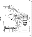
On a représenté sur les
- un anneau mobile 42 à léchettes d'étanchéité 32,
une virole 44 de fixation située immédiatement en aval de l'anneau mobile 42 par rapport au sens d'écoulement de l'air dans la turbomachine et- un
joint d'étanchéité 46 interposé entre l'anneau mobile 42 et la virole 44.
- a
movable ring 42 with sealingwipers 32, - a
ferrule 44 for fixing situated immediately downstream of themovable ring 42 with respect to the direction of flow of the air in the turbomachine and - a
seal 46 interposed between themovable ring 42 and theferrule 44.
Cet assemblage 4 est disposé entre un disque de rotor amont 20a et un disque de rotor aval 20b et relié à ceux-ci par l'intermédiaire d'une liaison boulonnée 26.This
La liaison boulonnée 26 met en prise une bride de fixation 442 de la virole 44, une bride de fixation 241 d'une virole aval 24 s'étendant à partir d'une portion annulaire externe du disque amont 20a, et une bride de fixation 221 d'une virole amont 22 s'étendant à partir d'une portion annulaire externe du disque aval 20b. Cet assemblage assure l'étanchéité entre la cavité amont et la cavité aval, permet la ventilation du disque de rotor aval 20b et maintient un anneau de retenue 27 en appui contre le disque aubagé amont 20a.The bolted
On va à présent décrire plus en détails les différents composants de l'assemblage.We will now describe in more detail the various components of the assembly.
L'anneau mobile 42 est une pièce de révolution autour d'un axe X-X de la turbomachine. Il comprend une bride annulaire aval 30 venant en appui contre une alvéole 18 du disque de rotor aval aubagé 20b. Les surfaces annulaires externe et interne de cette bride ont été référencées par 301 et 302.The
L'extrémité 303 de la bride 30, en appui contre l'alvéole 18, peut en outre comprendre une gorge annulaire 304 configurée pour recevoir un joint d'étanchéité annulaire 305. Ainsi, lors de l'échauffement de l'anneau mobile 42 soumis à l'écoulement d'air chaud, la dilatation radiale de l'extrémité 303 le long des parois de l'alvéole 18 n'entraîne pas de rupture d'étanchéité d'une cavité de diffusion d'air 60 ménagé entre la virole amont 22 du disque de rotor 20b, la bride 30 et la virole 44. Ainsi, le joint d'étanchéité annulaire 305 peut être en DMD0415 (HS25). L'espace 60 est notamment utile à la ventilation du disque aval 20b, comme il sera décrit plus précisément par la suite.The
Des léchettes radiales 32 d'étanchéité s'étendent à partir de la surface externe 301. Elles sont configurées pour coopérer en fonctionnement avec une surface interne 120 d'un moyeu annulaire portant les aubes fixes 12 du distributeur afin d'assurer l'étanchéité entre la cavité amont et la cavité aval située de part et d'autre du moyeu portant les aubes fixes 12.
L'anneau mobile 42 peut en outre comprendre une bride annulaire amont 31 qui s'étend à partir d'une collerette 420 de l'anneau mobile 42. Cette bride annulaire amont vient en appui contre l'anneau de retenue 27 afin de le maintenir contre le disque aubagé amont 20a. L'anneau de retenue 27 a pour fonction de retenir axialement les aubes mobiles 16.The
L'anneau mobile 42 est fretté, au niveau de sa base, sur la virole aval 24 du disque de rotor amont 20a.The
La liaison entre l'anneau mobile 42 et le disque de rotor amont 20a peut également servir à l'anti-rotation des différentes pièces de l'assemblage 4 les unes par rapport aux autres.The connection between the
Enfin, l'anneau mobile 42 comporte une bride annulaire dite d'anti-rotation 50 s'étendant radialement vers l'intérieur à partir de la surface annulaire radiale interne 302 de l'anneau, et présentant une série de rainures 52 s'étendant radialement vers l'intérieur, de manière périodique tout autour de la bride 50. La fonction de la bride 50 et des rainures 52 sera détaillée par la suite.Finally, the
La virole 44 comprend sur sa surface amont (surface 440) une gorge circonférentielle 45 configurée pour accueillir le joint d'étanchéité annulaire 46. Ce joint 46 est mis en compression entre la collerette 420 de l'anneau mobile 42 et la virole 44 par la liaison boulonnée 26. Ainsi, en cas de perte de la liaison entre l'anneau mobile 42 et la virole aval 24 du disque de rotor amont 20a, le joint 46 assure la continuité de l'étanchéité entre les cavités amont et aval de la turbine. De plus dans la mesure où le joint d'étanchéité 46 se trouve à l'interface entre deux pièces aux températures très différentes, c'est à présent à lui d'être soumis à fort gradient thermique. Par conséquent le joint d'étanchéité 46 peut être en DMD0415 (HS25).The
Par ailleurs, la virole 44 présente également, du côté aval (surface 441) une ou plusieurs lunules de refroidissement 43 disposées au-dessus de la liaison boulonnée 26, par exemple une série de lunules circonférentielles 43 régulièrement réparties au niveau d'une portion de surface tangentielle aval 441.Furthermore, the
Ces lunules 43 permettent une circulation d'air frais prélevé en amont de la turbine et circulant au travers de chaque liaison boulonnée 26. Cet air frais circulant depuis l'amont de la turbine est apte à passer à travers la lunule 43 jusque la cavité de diffusion d'air 60 avant de diffuser dans chaque alvéole 18 du disque 20b pour les ventiler.These
La virole de fixation 44 se termine, en dessous desdites lunules 43 par une bride de fixation 442 qui est configurée pour permettre la fixation de la virole 44 dans la liaison boulonnée 26. Pour cela, la bride 442 présente une série d'ouvertures réparties périodiquement et destinées à venir en regard d'une série d'ouvertures similaires pratiquées respectivement dans les brides 241 et 221 des viroles aval 24 du disque amont 20a et amont 22 du disque aval 20b.The fixing
À son extrémité opposée, la virole 44 peut comprendre une série de tenons d'anti-rotation 54 qui s'étendent en saillie par rapport au reste de ladite virole 44. Ces tenons sont espacés périodiquement tout autour de la virole 44 de sorte à être en regard de rainures 52 que présente de la bride 50 de l'anneau mobile 42 (
Les rainures 52 et tenons 54 sont configurés pour coopérer chacun les uns avec les autres tout autour de l'anneau 42 et de la virole 44 respectivement. Ils présentent donc des formes substantiellement complémentaires.The
L'anneau mobile 42 étant dissocié de la liaison boulonnée 26, ces rainures 52 et tenons 54 assurent le blocage en rotation des différentes pièces et la cohésion mécanique de l'assemblage 4.The
En plus de l'arrêt en rotation, le système de rainure-tenon décrit ci-dessus peut assurer le centrage de l'anneau 42 dans l'assemblage 4 en cas de perte du frettage de l'anneau 42.In addition to the rotation stop, the tenon-groove system described above can ensure the centering of the
Alternativement ou en complément, l'arrêt en rotation peut être permis par un système de rainures-tenons pratiqués à l'interface entre l'anneau mobile 42 et la virole aval 24 du disque amont 20a. Dans ce mode de réalisation, la bride annulaire 50 est frettée sur la portion annulaire externe de la virole 44.Alternatively or in addition, the rotation can be stopped by a system of tenon-grooves made at the interface between the
Dans un mode de réalisation illustré sur les
Comme illustré sur la
Alternativement, comme illustré sur la
De manière alternative, comme illustré sur la
La forme et les dimensions du crochet 410 et de l'alésage 412 peuvent varier en fonction de l'intensité du maintien recherché, mais aussi de considérations de facilité de montage, par exemple pour la maintenance. Il est ainsi possible de dimensionner l'alésage 412 de manière légèrement plus importante que le crochet 410, de sorte à laisser une marge de fonctionnement avant la mise en contact de la butée 41 pour ne pas tirer immédiatement sur la bride 442.The shape and dimensions of the
En outre, le crochet 410 peut avantageusement être fretté dans l'alésage 412, de sorte à favoriser le maintien offert par la butée 41.In addition, the
Par ailleurs, la butée de maintien 41 peut également comprendre plusieurs crochets 410 formés sur l'anneau 42 ou la virole 44, et coopérant avec plusieurs alésages 412 correspondant.Furthermore, the retaining
Enfin, le crochet 410 et l'alésage 412 peuvent être formés de révolution autour de l'axe longitudinal X-X, ou n'être formés que sur des portions angulaires successives, équiréparties ou non, autour de l'axe longitudinal X-X.Finally, the
Grâce à la butée de maintien 41, l'assemblage 4 est rendu plus robuste, notamment en cas de pertes de frettage de l'anneau mobile 42.Thanks to the retaining
L'assemblage proposé permet donc une augmentation de la durée de vie de turbine de turbomachine par réduction du phénomène d'ouverture de brides au niveau des liaisons boulonnées qui relient les différents disques de rotor de turbine.The proposed assembly therefore allows an increase in the life of a turbomachine turbine by reducing the phenomenon of flange opening at the bolted connections which connect the various turbine rotor discs.
En effet, lors de l'écoulement d'air chaud dans la turbine 10, l'anneau mobile 42 va s'échauffer. Dans la mesure où il n'y a plus de continuité mécanique entre l'anneau mobile 42 et la liaison boulonnée 26, seul l'anneau mobile 42 va se dilater. Par conséquent la partie annulaire externe de la virole 44 de fixation ne va plus « tirer » sur la bride 442 et n'entraînera donc pas de contraintes importantes sur les autres brides 221 et 241 de la liaison boulonnée 26.Indeed, during the flow of hot air in the
Par conséquent, la tenue mécanique des liaisons boulonnées 26 des turbines 10 de turbomachines comprenant un assemblage du type de l'assemblage 4 qui vient d'être décrit est améliorée. Il en résulte une augmentation de leur durée de vie.Consequently, the mechanical strength of the bolted
Claims (14)
- A turbine engine turbine (10) movable ring assembly (4) which is mounted between two successive rotor disks, (20a) and (20b) of said turbine (10), said rotors disks (20a) and (20b) being fixed to one another by bolts, characterized in that it comprises:- a fixing ferrule (44) fixed between the upstream (20a) and downstream (20b) disks by bolting them, and- a part forming a movable ring (42), said part bearing radial sealing members (32) and being fixed between the upstream disk (20a) and the ferrule (44).
- The movable ring assembly (4) according to claim 1, further comprising a seal (46) interposed between the part forming a movable ring (42) and the ferrule (44).
- The movable ring assembly (4) according to one of the preceding claims, wherein the movable ring (42) is shrink-fit on the upstream disk (20a).
- The movable ring assembly (4) according to one of the preceding claims wherein the ferrule (44) comprises at least one lunule (43) above the bolted connection (26).
- The movable ring assembly (4) according to claim 4, wherein the ferrule comprises several lunules distributed regularly at a portion of a downstream tangential surface (441) of the ferrule (44).
- The movable ring assembly (4) according to one of the preceding claims, including a set of slots (52) and of lugs (54) ensuring the non-rotation of the movable ring (42) with respect to the ferrule (44).
- The movable ring assembly (4) according to claim 6, wherein the slots (52) are disposed in the movable ring (42) and the lugs (54) extend from the ferrule (44).
- The movable ring assembly (4) according to claim 7, wherein the slots (52) of the movable ring (42) are disposed in an anti-rotation flange (50) extending from an inner annular surface of the movable ring (42), and distributed periodically over an annular area of said flange (50) distant from the inner annular surface of the movable ring (42).
- The movable ring assembly (4) according to claim 7, wherein the lugs (54) are distributed periodically and regularly over an outer annular surface of the ferrule (44), facing the corresponding slots of the anti-rotation flange (50) of the movable ring (42).
- The movable ring assembly (4) according to one of the preceding claims, wherein the movable ring (42) further comprises an upstream annular flange (31) extending from a portion of an upstream tangential surface (420) of the movable ring and maintaining a retaining ring (27) bearing against the upstream bladed disk (20a).
- The movable ring assembly (4) according to one of the preceding claims, further comprising a retaining abutment of the movable ring (42), said abutment comprising a hook (410) cooperating with a bore (412).
- The movable ring assembly (4) according to claim 11, wherein the hook (410) is formed on the movable ring (42) and the bore (412) is provided in the ferrule (44).
- The movable ring assembly (4) according to claim 11, wherein the hook (410) is formed on the ferrule (44) and the bore (412) is provided in the movable ring (42).
- A turbojet comprising a movable ring assembly (4) according to any one of the preceding claims.
Applications Claiming Priority (2)
| Application Number | Priority Date | Filing Date | Title |
|---|---|---|---|
| FR1659685A FR3057300B1 (en) | 2016-10-07 | 2016-10-07 | MOBILE RING ASSEMBLY OF TURBOMACHINE TURBINE |
| PCT/FR2017/052746 WO2018065739A1 (en) | 2016-10-07 | 2017-10-06 | Movable ring assembly for a turbine engine turbine |
Publications (2)
| Publication Number | Publication Date |
|---|---|
| EP3523507A1 EP3523507A1 (en) | 2019-08-14 |
| EP3523507B1 true EP3523507B1 (en) | 2020-06-24 |
Family
ID=57963254
Family Applications (1)
| Application Number | Title | Priority Date | Filing Date |
|---|---|---|---|
| EP17786988.0A Active EP3523507B1 (en) | 2016-10-07 | 2017-10-06 | Movable ring assembly for a turbine engine turbine |
Country Status (5)
| Country | Link |
|---|---|
| US (1) | US10920593B2 (en) |
| EP (1) | EP3523507B1 (en) |
| CN (1) | CN109844264B (en) |
| FR (1) | FR3057300B1 (en) |
| WO (1) | WO2018065739A1 (en) |
Cited By (1)
| Publication number | Priority date | Publication date | Assignee | Title |
|---|---|---|---|---|
| EP4170237A1 (en) * | 2021-10-21 | 2023-04-26 | Raytheon Technologies Corporation | Tongue joint including mating channel for cooling |
Families Citing this family (10)
| Publication number | Priority date | Publication date | Assignee | Title |
|---|---|---|---|---|
| EP3318723B1 (en) * | 2016-11-04 | 2021-01-13 | Siemens Aktiengesellschaft | Sealing ring of a rotor and rotor |
| FR3086328B1 (en) * | 2018-09-20 | 2021-01-01 | Safran Aircraft Engines | IMPELLER WITH AXIALLY RETAINED BLADES, FOR TURBOMACHINE |
| IT201900014739A1 (en) * | 2019-08-13 | 2021-02-13 | Ge Avio Srl | Elements for retaining blades for turbomachinery. |
| FR3108361B1 (en) * | 2020-03-19 | 2023-05-12 | Safran Aircraft Engines | TURBINE WHEEL FOR AN AIRCRAFT TURBOMACHINE |
| FR3108938B1 (en) | 2020-04-02 | 2022-03-04 | Safran Aircraft Engines | Sealing ring for a turbomachine turbine rotor |
| FR3111157B1 (en) * | 2020-06-05 | 2022-07-22 | Safran Aircraft Engines | Motor comprising a sealing member between two rotor elements |
| FR3120092A1 (en) * | 2021-02-24 | 2022-08-26 | Safran Aircraft Engines | Impeller sealing ring |
| FR3120894B1 (en) * | 2021-03-19 | 2023-02-24 | Safran Aircraft Engines | TURBOMACHINE ROTOR, INCLUDING A LABYRINTH SEAL RING MOUNTED ON DISC FERRULES |
| US11821320B2 (en) | 2021-06-04 | 2023-11-21 | General Electric Company | Turbine engine with a rotor seal assembly |
| FR3131599B1 (en) | 2022-01-04 | 2023-12-15 | Safran Aircraft Engines | ASSEMBLY OF A FERRULE AND A RING |
Citations (6)
| Publication number | Priority date | Publication date | Assignee | Title |
|---|---|---|---|---|
| EP0921277A1 (en) | 1997-06-04 | 1999-06-09 | Mitsubishi Heavy Industries, Ltd. | Seal structure between gas turbine discs |
| EP2208860A2 (en) | 2009-01-14 | 2010-07-21 | General Electric Company | Interstage seal for a gas turbine and corresponding gas turbine |
| FR2973433A1 (en) | 2011-04-04 | 2012-10-05 | Snecma | Turbine rotor for low pressure turbomachine e.g. turbojet of aircraft, has upstream and downstream disks arranged coaxially, and bearing unit supporting end portion of flange to prevent deviation of flange of downstream disk |
| FR3009336A1 (en) | 2013-08-05 | 2015-02-06 | Snecma | ROTARY TURBOMACHINE ASSEMBLY WITH A VIROLE LABYRINTHE CMC |
| WO2015177429A1 (en) | 2014-05-20 | 2015-11-26 | Snecma | Turbine rotor for a gas-turbine engine |
| WO2016059348A1 (en) | 2014-10-15 | 2016-04-21 | Snecma | Rotary assembly for a turbine engine comprising a self-supported rotor collar |
Family Cites Families (12)
| Publication number | Priority date | Publication date | Assignee | Title |
|---|---|---|---|---|
| US5080556A (en) * | 1990-09-28 | 1992-01-14 | General Electric Company | Thermal seal for a gas turbine spacer disc |
| FR2712029B1 (en) * | 1993-11-03 | 1995-12-08 | Snecma | Turbomachine provided with a means for reheating the turbine disks when running at high speed. |
| JPH09242563A (en) * | 1996-03-11 | 1997-09-16 | Hitachi Ltd | Gas turbine cooling system |
| FR2825748B1 (en) * | 2001-06-07 | 2003-11-07 | Snecma Moteurs | TURBOMACHINE ROTOR ARRANGEMENT WITH TWO BLADE DISCS SEPARATED BY A SPACER |
| FR2868814B1 (en) * | 2004-04-09 | 2009-12-18 | Snecma Moteurs | DEVICE FOR ASSEMBLING ANNULAR FLANGES, PARTICULARLY IN A TURBOMACHINE |
| FR2928963B1 (en) * | 2008-03-19 | 2017-12-08 | Snecma | TURBINE DISPENSER FOR A TURBOMACHINE. |
| FR2937371B1 (en) * | 2008-10-20 | 2010-12-10 | Snecma | VENTILATION OF A HIGH-PRESSURE TURBINE IN A TURBOMACHINE |
| FR2939836B1 (en) * | 2008-12-12 | 2015-05-15 | Snecma | SEAL FOR PLATFORM SEAL IN A TURBOMACHINE ROTOR |
| FR2946083B1 (en) * | 2009-05-28 | 2011-06-17 | Snecma | LOW PRESSURE TURBINE |
| FR2982635B1 (en) * | 2011-11-15 | 2013-11-15 | Snecma | AUBES WHEEL FOR A TURBOMACHINE |
| FR3006366B1 (en) * | 2013-05-28 | 2018-03-02 | Safran Aircraft Engines | TURBINE WHEEL IN A TURBOMACHINE |
| FR3020408B1 (en) * | 2014-04-24 | 2018-04-06 | Safran Aircraft Engines | ROTARY ASSEMBLY FOR TURBOMACHINE |
-
2016
- 2016-10-07 FR FR1659685A patent/FR3057300B1/en active Active
-
2017
- 2017-10-06 EP EP17786988.0A patent/EP3523507B1/en active Active
- 2017-10-06 WO PCT/FR2017/052746 patent/WO2018065739A1/en unknown
- 2017-10-06 CN CN201780062161.5A patent/CN109844264B/en active Active
- 2017-10-06 US US16/339,801 patent/US10920593B2/en active Active
Patent Citations (6)
| Publication number | Priority date | Publication date | Assignee | Title |
|---|---|---|---|---|
| EP0921277A1 (en) | 1997-06-04 | 1999-06-09 | Mitsubishi Heavy Industries, Ltd. | Seal structure between gas turbine discs |
| EP2208860A2 (en) | 2009-01-14 | 2010-07-21 | General Electric Company | Interstage seal for a gas turbine and corresponding gas turbine |
| FR2973433A1 (en) | 2011-04-04 | 2012-10-05 | Snecma | Turbine rotor for low pressure turbomachine e.g. turbojet of aircraft, has upstream and downstream disks arranged coaxially, and bearing unit supporting end portion of flange to prevent deviation of flange of downstream disk |
| FR3009336A1 (en) | 2013-08-05 | 2015-02-06 | Snecma | ROTARY TURBOMACHINE ASSEMBLY WITH A VIROLE LABYRINTHE CMC |
| WO2015177429A1 (en) | 2014-05-20 | 2015-11-26 | Snecma | Turbine rotor for a gas-turbine engine |
| WO2016059348A1 (en) | 2014-10-15 | 2016-04-21 | Snecma | Rotary assembly for a turbine engine comprising a self-supported rotor collar |
Cited By (2)
| Publication number | Priority date | Publication date | Assignee | Title |
|---|---|---|---|---|
| EP4170237A1 (en) * | 2021-10-21 | 2023-04-26 | Raytheon Technologies Corporation | Tongue joint including mating channel for cooling |
| US11933221B2 (en) | 2021-10-21 | 2024-03-19 | Rtx Corporation | Tongue joint including mating channel for cooling |
Also Published As
| Publication number | Publication date |
|---|---|
| WO2018065739A1 (en) | 2018-04-12 |
| US20200040735A1 (en) | 2020-02-06 |
| CN109844264B (en) | 2021-04-30 |
| FR3057300A1 (en) | 2018-04-13 |
| FR3057300B1 (en) | 2018-10-05 |
| CN109844264A (en) | 2019-06-04 |
| EP3523507A1 (en) | 2019-08-14 |
| US10920593B2 (en) | 2021-02-16 |
Similar Documents
| Publication | Publication Date | Title |
|---|---|---|
| EP3523507B1 (en) | Movable ring assembly for a turbine engine turbine | |
| EP1965027B1 (en) | High-pressure turbine of a turbomachine | |
| CA2925438C (en) | Rotary assembly for a turbomachine | |
| EP3746639B1 (en) | Assembly for a turbine of a turbomachine comprising a mobile sealing ring | |
| EP3049637B1 (en) | Rotary assembly for turbomachine | |
| EP1517005A1 (en) | Gas turbine sealing joint having lamellar structure | |
| FR3020408A1 (en) | ROTARY ASSEMBLY FOR TURBOMACHINE | |
| FR3021348A1 (en) | TURBINE ROTOR FOR A GAS TURBINE ENGINE | |
| FR3068070B1 (en) | TURBINE FOR TURBOMACHINE | |
| FR2978793A1 (en) | Turbine rotor for e.g. turbojet engine of aircraft, has annular ring deformed or moved in order to compensate deformation/displacement of plate so as to ensure sealing of annular space irrespective of position of plate | |
| EP3152404B1 (en) | Rotor for turbine engine comprising blades with added platforms | |
| FR2961848A1 (en) | TURBINE FLOOR | |
| FR3000985A1 (en) | Cooling device for casing of turbine for turboshaft engine, has supply unit for directly providing part of air of power supply enclosure of low pressure module of turbine, in housing without allowing air to pass by cooling pipe | |
| FR3088671A1 (en) | SEALING BETWEEN A MOBILE WHEEL AND A DISTRIBUTOR OF A TURBOMACHINE | |
| FR3087825A1 (en) | TURBINE RING SECTOR WITH COOLED SEALING TONGS | |
| FR3078363A1 (en) | MOBILE SEAL RING | |
| FR3073001A1 (en) | TURBINE DISK ASSEMBLY | |
| EP4133161A1 (en) | Turbine rotor for a turbomachine and method for mounting the rotor | |
| FR3101374A1 (en) | Cooling structure of a turbine with radial cooperation between sealing ring and moving wheel disc | |
| FR3011270A1 (en) | DEVICE FOR CONNECTING A FIXED PART OF A TURBOMACHINE AND A DISTRIBUTOR FOOT OF A TURBOMACHINE TURBINE | |
| EP3853445B1 (en) | Turbine seal | |
| FR2961556A1 (en) | Turbine i.e. low pressure turbine, for e.g. turbojet engine of airplane, has axial and radial support units that are not in contact with casing to avoid heating, by conduction, of casing by sectorized ring during operation | |
| FR3137415A1 (en) | Sealing assembly for low pressure turbine stator and low pressure turbine ring comprising such a sealing assembly | |
| FR3121473A1 (en) | Fixing shells in a turbomachine | |
| FR3113419A1 (en) | DISTRIBUTOR OF A TURBOMACHINE TURBINE |
Legal Events
| Date | Code | Title | Description |
|---|---|---|---|
| STAA | Information on the status of an ep patent application or granted ep patent |
Free format text: STATUS: UNKNOWN |
|
| STAA | Information on the status of an ep patent application or granted ep patent |
Free format text: STATUS: THE INTERNATIONAL PUBLICATION HAS BEEN MADE |
|
| PUAI | Public reference made under article 153(3) epc to a published international application that has entered the european phase |
Free format text: ORIGINAL CODE: 0009012 |
|
| STAA | Information on the status of an ep patent application or granted ep patent |
Free format text: STATUS: REQUEST FOR EXAMINATION WAS MADE |
|
| 17P | Request for examination filed |
Effective date: 20190506 |
|
| AK | Designated contracting states |
Kind code of ref document: A1 Designated state(s): AL AT BE BG CH CY CZ DE DK EE ES FI FR GB GR HR HU IE IS IT LI LT LU LV MC MK MT NL NO PL PT RO RS SE SI SK SM TR |
|
| AX | Request for extension of the european patent |
Extension state: BA ME |
|
| DAV | Request for validation of the european patent (deleted) | ||
| DAX | Request for extension of the european patent (deleted) | ||
| GRAP | Despatch of communication of intention to grant a patent |
Free format text: ORIGINAL CODE: EPIDOSNIGR1 |
|
| STAA | Information on the status of an ep patent application or granted ep patent |
Free format text: STATUS: GRANT OF PATENT IS INTENDED |
|
| INTG | Intention to grant announced |
Effective date: 20200217 |
|
| GRAS | Grant fee paid |
Free format text: ORIGINAL CODE: EPIDOSNIGR3 |
|
| GRAA | (expected) grant |
Free format text: ORIGINAL CODE: 0009210 |
|
| STAA | Information on the status of an ep patent application or granted ep patent |
Free format text: STATUS: THE PATENT HAS BEEN GRANTED |
|
| AK | Designated contracting states |
Kind code of ref document: B1 Designated state(s): AL AT BE BG CH CY CZ DE DK EE ES FI FR GB GR HR HU IE IS IT LI LT LU LV MC MK MT NL NO PL PT RO RS SE SI SK SM TR |
|
| REG | Reference to a national code |
Ref country code: GB Ref legal event code: FG4D Free format text: NOT ENGLISH |
|
| REG | Reference to a national code |
Ref country code: CH Ref legal event code: EP |
|
| REG | Reference to a national code |
Ref country code: AT Ref legal event code: REF Ref document number: 1284087 Country of ref document: AT Kind code of ref document: T Effective date: 20200715 |
|
| REG | Reference to a national code |
Ref country code: DE Ref legal event code: R096 Ref document number: 602017018794 Country of ref document: DE |
|
| REG | Reference to a national code |
Ref country code: IE Ref legal event code: FG4D Free format text: LANGUAGE OF EP DOCUMENT: FRENCH |
|
| REG | Reference to a national code |
Ref country code: SE Ref legal event code: TRGR |
|
| PG25 | Lapsed in a contracting state [announced via postgrant information from national office to epo] |
Ref country code: FI Free format text: LAPSE BECAUSE OF FAILURE TO SUBMIT A TRANSLATION OF THE DESCRIPTION OR TO PAY THE FEE WITHIN THE PRESCRIBED TIME-LIMIT Effective date: 20200624 Ref country code: NO Free format text: LAPSE BECAUSE OF FAILURE TO SUBMIT A TRANSLATION OF THE DESCRIPTION OR TO PAY THE FEE WITHIN THE PRESCRIBED TIME-LIMIT Effective date: 20200924 Ref country code: GR Free format text: LAPSE BECAUSE OF FAILURE TO SUBMIT A TRANSLATION OF THE DESCRIPTION OR TO PAY THE FEE WITHIN THE PRESCRIBED TIME-LIMIT Effective date: 20200925 Ref country code: LT Free format text: LAPSE BECAUSE OF FAILURE TO SUBMIT A TRANSLATION OF THE DESCRIPTION OR TO PAY THE FEE WITHIN THE PRESCRIBED TIME-LIMIT Effective date: 20200624 |
|
| REG | Reference to a national code |
Ref country code: LT Ref legal event code: MG4D |
|
| PG25 | Lapsed in a contracting state [announced via postgrant information from national office to epo] |
Ref country code: RS Free format text: LAPSE BECAUSE OF FAILURE TO SUBMIT A TRANSLATION OF THE DESCRIPTION OR TO PAY THE FEE WITHIN THE PRESCRIBED TIME-LIMIT Effective date: 20200624 Ref country code: BG Free format text: LAPSE BECAUSE OF FAILURE TO SUBMIT A TRANSLATION OF THE DESCRIPTION OR TO PAY THE FEE WITHIN THE PRESCRIBED TIME-LIMIT Effective date: 20200924 Ref country code: LV Free format text: LAPSE BECAUSE OF FAILURE TO SUBMIT A TRANSLATION OF THE DESCRIPTION OR TO PAY THE FEE WITHIN THE PRESCRIBED TIME-LIMIT Effective date: 20200624 Ref country code: HR Free format text: LAPSE BECAUSE OF FAILURE TO SUBMIT A TRANSLATION OF THE DESCRIPTION OR TO PAY THE FEE WITHIN THE PRESCRIBED TIME-LIMIT Effective date: 20200624 |
|
| REG | Reference to a national code |
Ref country code: NL Ref legal event code: MP Effective date: 20200624 |
|
| REG | Reference to a national code |
Ref country code: AT Ref legal event code: MK05 Ref document number: 1284087 Country of ref document: AT Kind code of ref document: T Effective date: 20200624 |
|
| PG25 | Lapsed in a contracting state [announced via postgrant information from national office to epo] |
Ref country code: AL Free format text: LAPSE BECAUSE OF FAILURE TO SUBMIT A TRANSLATION OF THE DESCRIPTION OR TO PAY THE FEE WITHIN THE PRESCRIBED TIME-LIMIT Effective date: 20200624 Ref country code: NL Free format text: LAPSE BECAUSE OF FAILURE TO SUBMIT A TRANSLATION OF THE DESCRIPTION OR TO PAY THE FEE WITHIN THE PRESCRIBED TIME-LIMIT Effective date: 20200624 |
|
| PG25 | Lapsed in a contracting state [announced via postgrant information from national office to epo] |
Ref country code: AT Free format text: LAPSE BECAUSE OF FAILURE TO SUBMIT A TRANSLATION OF THE DESCRIPTION OR TO PAY THE FEE WITHIN THE PRESCRIBED TIME-LIMIT Effective date: 20200624 Ref country code: EE Free format text: LAPSE BECAUSE OF FAILURE TO SUBMIT A TRANSLATION OF THE DESCRIPTION OR TO PAY THE FEE WITHIN THE PRESCRIBED TIME-LIMIT Effective date: 20200624 Ref country code: SM Free format text: LAPSE BECAUSE OF FAILURE TO SUBMIT A TRANSLATION OF THE DESCRIPTION OR TO PAY THE FEE WITHIN THE PRESCRIBED TIME-LIMIT Effective date: 20200624 Ref country code: CZ Free format text: LAPSE BECAUSE OF FAILURE TO SUBMIT A TRANSLATION OF THE DESCRIPTION OR TO PAY THE FEE WITHIN THE PRESCRIBED TIME-LIMIT Effective date: 20200624 Ref country code: RO Free format text: LAPSE BECAUSE OF FAILURE TO SUBMIT A TRANSLATION OF THE DESCRIPTION OR TO PAY THE FEE WITHIN THE PRESCRIBED TIME-LIMIT Effective date: 20200624 Ref country code: ES Free format text: LAPSE BECAUSE OF FAILURE TO SUBMIT A TRANSLATION OF THE DESCRIPTION OR TO PAY THE FEE WITHIN THE PRESCRIBED TIME-LIMIT Effective date: 20200624 Ref country code: PT Free format text: LAPSE BECAUSE OF FAILURE TO SUBMIT A TRANSLATION OF THE DESCRIPTION OR TO PAY THE FEE WITHIN THE PRESCRIBED TIME-LIMIT Effective date: 20201026 |
|
| PG25 | Lapsed in a contracting state [announced via postgrant information from national office to epo] |
Ref country code: PL Free format text: LAPSE BECAUSE OF FAILURE TO SUBMIT A TRANSLATION OF THE DESCRIPTION OR TO PAY THE FEE WITHIN THE PRESCRIBED TIME-LIMIT Effective date: 20200624 Ref country code: SK Free format text: LAPSE BECAUSE OF FAILURE TO SUBMIT A TRANSLATION OF THE DESCRIPTION OR TO PAY THE FEE WITHIN THE PRESCRIBED TIME-LIMIT Effective date: 20200624 Ref country code: IS Free format text: LAPSE BECAUSE OF FAILURE TO SUBMIT A TRANSLATION OF THE DESCRIPTION OR TO PAY THE FEE WITHIN THE PRESCRIBED TIME-LIMIT Effective date: 20201024 |
|
| REG | Reference to a national code |
Ref country code: DE Ref legal event code: R026 Ref document number: 602017018794 Country of ref document: DE |
|
| PLBI | Opposition filed |
Free format text: ORIGINAL CODE: 0009260 |
|
| PLAX | Notice of opposition and request to file observation + time limit sent |
Free format text: ORIGINAL CODE: EPIDOSNOBS2 |
|
| 26 | Opposition filed |
Opponent name: RAYTHEON TECHNOLOGIES CORPORATION Effective date: 20210323 |
|
| PG25 | Lapsed in a contracting state [announced via postgrant information from national office to epo] |
Ref country code: DK Free format text: LAPSE BECAUSE OF FAILURE TO SUBMIT A TRANSLATION OF THE DESCRIPTION OR TO PAY THE FEE WITHIN THE PRESCRIBED TIME-LIMIT Effective date: 20200624 |
|
| REG | Reference to a national code |
Ref country code: CH Ref legal event code: PL |
|
| PG25 | Lapsed in a contracting state [announced via postgrant information from national office to epo] |
Ref country code: LU Free format text: LAPSE BECAUSE OF NON-PAYMENT OF DUE FEES Effective date: 20201006 Ref country code: MC Free format text: LAPSE BECAUSE OF FAILURE TO SUBMIT A TRANSLATION OF THE DESCRIPTION OR TO PAY THE FEE WITHIN THE PRESCRIBED TIME-LIMIT Effective date: 20200624 |
|
| REG | Reference to a national code |
Ref country code: BE Ref legal event code: MM Effective date: 20201031 |
|
| PLBB | Reply of patent proprietor to notice(s) of opposition received |
Free format text: ORIGINAL CODE: EPIDOSNOBS3 |
|
| PG25 | Lapsed in a contracting state [announced via postgrant information from national office to epo] |
Ref country code: CH Free format text: LAPSE BECAUSE OF NON-PAYMENT OF DUE FEES Effective date: 20201031 Ref country code: BE Free format text: LAPSE BECAUSE OF NON-PAYMENT OF DUE FEES Effective date: 20201031 Ref country code: SI Free format text: LAPSE BECAUSE OF FAILURE TO SUBMIT A TRANSLATION OF THE DESCRIPTION OR TO PAY THE FEE WITHIN THE PRESCRIBED TIME-LIMIT Effective date: 20200624 Ref country code: LI Free format text: LAPSE BECAUSE OF NON-PAYMENT OF DUE FEES Effective date: 20201031 |
|
| PG25 | Lapsed in a contracting state [announced via postgrant information from national office to epo] |
Ref country code: IE Free format text: LAPSE BECAUSE OF NON-PAYMENT OF DUE FEES Effective date: 20201006 |
|
| PG25 | Lapsed in a contracting state [announced via postgrant information from national office to epo] |
Ref country code: TR Free format text: LAPSE BECAUSE OF FAILURE TO SUBMIT A TRANSLATION OF THE DESCRIPTION OR TO PAY THE FEE WITHIN THE PRESCRIBED TIME-LIMIT Effective date: 20200624 Ref country code: MT Free format text: LAPSE BECAUSE OF FAILURE TO SUBMIT A TRANSLATION OF THE DESCRIPTION OR TO PAY THE FEE WITHIN THE PRESCRIBED TIME-LIMIT Effective date: 20200624 Ref country code: CY Free format text: LAPSE BECAUSE OF FAILURE TO SUBMIT A TRANSLATION OF THE DESCRIPTION OR TO PAY THE FEE WITHIN THE PRESCRIBED TIME-LIMIT Effective date: 20200624 |
|
| PG25 | Lapsed in a contracting state [announced via postgrant information from national office to epo] |
Ref country code: MK Free format text: LAPSE BECAUSE OF FAILURE TO SUBMIT A TRANSLATION OF THE DESCRIPTION OR TO PAY THE FEE WITHIN THE PRESCRIBED TIME-LIMIT Effective date: 20200624 |
|
| APBM | Appeal reference recorded |
Free format text: ORIGINAL CODE: EPIDOSNREFNO |
|
| APBP | Date of receipt of notice of appeal recorded |
Free format text: ORIGINAL CODE: EPIDOSNNOA2O |
|
| APAH | Appeal reference modified |
Free format text: ORIGINAL CODE: EPIDOSCREFNO |
|
| APBQ | Date of receipt of statement of grounds of appeal recorded |
Free format text: ORIGINAL CODE: EPIDOSNNOA3O |
|
| PGFP | Annual fee paid to national office [announced via postgrant information from national office to epo] |
Ref country code: IT Payment date: 20230920 Year of fee payment: 7 Ref country code: GB Payment date: 20230920 Year of fee payment: 7 |
|
| PGFP | Annual fee paid to national office [announced via postgrant information from national office to epo] |
Ref country code: SE Payment date: 20230922 Year of fee payment: 7 Ref country code: FR Payment date: 20230920 Year of fee payment: 7 |
|
| PGFP | Annual fee paid to national office [announced via postgrant information from national office to epo] |
Ref country code: DE Payment date: 20230920 Year of fee payment: 7 |