EP3049564B1 - Nonwoven web with highly detailed and structurally advantageous bond pattern - Google Patents
Nonwoven web with highly detailed and structurally advantageous bond pattern Download PDFInfo
- Publication number
- EP3049564B1 EP3049564B1 EP14782012.0A EP14782012A EP3049564B1 EP 3049564 B1 EP3049564 B1 EP 3049564B1 EP 14782012 A EP14782012 A EP 14782012A EP 3049564 B1 EP3049564 B1 EP 3049564B1
- Authority
- EP
- European Patent Office
- Prior art keywords
- fibrous structure
- bonding
- filaments
- wipe
- fibers
- Prior art date
- Legal status (The legal status is an assumption and is not a legal conclusion. Google has not performed a legal analysis and makes no representation as to the accuracy of the status listed.)
- Active
Links
- 239000000203 mixture Substances 0.000 claims description 114
- 239000000835 fiber Substances 0.000 claims description 112
- -1 polypropylene Polymers 0.000 claims description 43
- 239000004743 Polypropylene Substances 0.000 claims description 31
- 229920001155 polypropylene Polymers 0.000 claims description 31
- 239000006185 dispersion Substances 0.000 claims description 30
- 229920001131 Pulp (paper) Polymers 0.000 claims description 24
- 238000013461 design Methods 0.000 claims description 14
- 229920002678 cellulose Polymers 0.000 claims description 8
- 239000001913 cellulose Substances 0.000 claims description 8
- 229920001169 thermoplastic Polymers 0.000 claims description 8
- 239000004372 Polyvinyl alcohol Substances 0.000 claims description 7
- 229920002451 polyvinyl alcohol Polymers 0.000 claims description 7
- 229920000098 polyolefin Polymers 0.000 claims description 6
- 239000004698 Polyethylene Substances 0.000 claims description 5
- 229920000573 polyethylene Polymers 0.000 claims description 5
- 239000005014 poly(hydroxyalkanoate) Substances 0.000 claims description 3
- 229920000747 poly(lactic acid) Polymers 0.000 claims description 3
- 229920001610 polycaprolactone Polymers 0.000 claims description 3
- 239000004632 polycaprolactone Substances 0.000 claims description 3
- 229920000728 polyester Polymers 0.000 claims description 3
- 229920000903 polyhydroxyalkanoate Polymers 0.000 claims description 3
- 239000004626 polylactic acid Substances 0.000 claims description 3
- 238000005096 rolling process Methods 0.000 claims description 2
- 239000007788 liquid Substances 0.000 description 104
- 238000012360 testing method Methods 0.000 description 80
- 238000000034 method Methods 0.000 description 65
- 239000011148 porous material Substances 0.000 description 59
- 239000000523 sample Substances 0.000 description 49
- 239000000463 material Substances 0.000 description 39
- 239000000654 additive Substances 0.000 description 34
- 239000007787 solid Substances 0.000 description 32
- 239000000047 product Substances 0.000 description 29
- 230000008569 process Effects 0.000 description 28
- 238000010998 test method Methods 0.000 description 24
- 239000012530 fluid Substances 0.000 description 23
- 239000006210 lotion Substances 0.000 description 20
- 239000000843 powder Substances 0.000 description 19
- 239000000123 paper Substances 0.000 description 18
- XLYOFNOQVPJJNP-UHFFFAOYSA-N water Substances O XLYOFNOQVPJJNP-UHFFFAOYSA-N 0.000 description 17
- 238000011068 loading method Methods 0.000 description 16
- 239000002689 soil Substances 0.000 description 15
- 239000003795 chemical substances by application Substances 0.000 description 13
- 239000002253 acid Substances 0.000 description 12
- 238000005259 measurement Methods 0.000 description 12
- 238000009826 distribution Methods 0.000 description 11
- 239000000155 melt Substances 0.000 description 11
- 239000001993 wax Substances 0.000 description 11
- 230000000996 additive effect Effects 0.000 description 10
- 238000004140 cleaning Methods 0.000 description 10
- 230000006835 compression Effects 0.000 description 10
- 238000007906 compression Methods 0.000 description 10
- 230000002745 absorbent Effects 0.000 description 9
- 239000002250 absorbent Substances 0.000 description 9
- 238000004458 analytical method Methods 0.000 description 9
- 238000010521 absorption reaction Methods 0.000 description 8
- IPCSVZSSVZVIGE-UHFFFAOYSA-N hexadecanoic acid Chemical compound CCCCCCCCCCCCCCCC(O)=O IPCSVZSSVZVIGE-UHFFFAOYSA-N 0.000 description 8
- 239000011230 binding agent Substances 0.000 description 7
- 238000004519 manufacturing process Methods 0.000 description 7
- 230000000007 visual effect Effects 0.000 description 7
- 150000007513 acids Chemical class 0.000 description 6
- 239000000853 adhesive Substances 0.000 description 6
- 230000009286 beneficial effect Effects 0.000 description 6
- 238000004364 calculation method Methods 0.000 description 6
- 235000010980 cellulose Nutrition 0.000 description 6
- KRKNYBCHXYNGOX-UHFFFAOYSA-N citric acid Chemical compound OC(=O)CC(O)(C(O)=O)CC(O)=O KRKNYBCHXYNGOX-UHFFFAOYSA-N 0.000 description 6
- 239000012153 distilled water Substances 0.000 description 6
- 230000006870 function Effects 0.000 description 6
- 230000000670 limiting effect Effects 0.000 description 6
- 229920000642 polymer Polymers 0.000 description 6
- 239000002952 polymeric resin Substances 0.000 description 6
- 235000019422 polyvinyl alcohol Nutrition 0.000 description 6
- 229920003002 synthetic resin Polymers 0.000 description 6
- 239000011800 void material Substances 0.000 description 6
- 229920002472 Starch Polymers 0.000 description 5
- 230000001070 adhesive effect Effects 0.000 description 5
- 230000001143 conditioned effect Effects 0.000 description 5
- 239000013068 control sample Substances 0.000 description 5
- 230000002209 hydrophobic effect Effects 0.000 description 5
- 239000003607 modifier Substances 0.000 description 5
- 239000000243 solution Substances 0.000 description 5
- 239000008107 starch Substances 0.000 description 5
- 235000019698 starch Nutrition 0.000 description 5
- 238000003756 stirring Methods 0.000 description 5
- 239000000126 substance Substances 0.000 description 5
- 239000004094 surface-active agent Substances 0.000 description 5
- 238000011282 treatment Methods 0.000 description 5
- 235000013311 vegetables Nutrition 0.000 description 5
- 229920002488 Hemicellulose Polymers 0.000 description 4
- 235000021314 Palmitic acid Nutrition 0.000 description 4
- 230000008901 benefit Effects 0.000 description 4
- CJZGTCYPCWQAJB-UHFFFAOYSA-L calcium stearate Chemical compound [Ca+2].CCCCCCCCCCCCCCCCCC([O-])=O.CCCCCCCCCCCCCCCCCC([O-])=O CJZGTCYPCWQAJB-UHFFFAOYSA-L 0.000 description 4
- 235000013539 calcium stearate Nutrition 0.000 description 4
- 239000008116 calcium stearate Substances 0.000 description 4
- 235000011967 chocolate pudding Nutrition 0.000 description 4
- 230000003750 conditioning effect Effects 0.000 description 4
- 229920001577 copolymer Polymers 0.000 description 4
- 238000000151 deposition Methods 0.000 description 4
- 238000004049 embossing Methods 0.000 description 4
- 238000010438 heat treatment Methods 0.000 description 4
- 239000004615 ingredient Substances 0.000 description 4
- 230000007246 mechanism Effects 0.000 description 4
- WQEPLUUGTLDZJY-UHFFFAOYSA-N n-Pentadecanoic acid Natural products CCCCCCCCCCCCCCC(O)=O WQEPLUUGTLDZJY-UHFFFAOYSA-N 0.000 description 4
- 239000002245 particle Substances 0.000 description 4
- 230000035699 permeability Effects 0.000 description 4
- 235000011962 puddings Nutrition 0.000 description 4
- 150000003839 salts Chemical class 0.000 description 4
- 239000000758 substrate Substances 0.000 description 4
- 239000004416 thermosoftening plastic Substances 0.000 description 4
- 239000000080 wetting agent Substances 0.000 description 4
- 229920002134 Carboxymethyl cellulose Polymers 0.000 description 3
- 229920000881 Modified starch Polymers 0.000 description 3
- OFOBLEOULBTSOW-UHFFFAOYSA-N Propanedioic acid Natural products OC(=O)CC(O)=O OFOBLEOULBTSOW-UHFFFAOYSA-N 0.000 description 3
- 229920000297 Rayon Polymers 0.000 description 3
- 239000004902 Softening Agent Substances 0.000 description 3
- 229920004890 Triton X-100 Polymers 0.000 description 3
- 239000003945 anionic surfactant Substances 0.000 description 3
- 239000002585 base Substances 0.000 description 3
- 239000001768 carboxy methyl cellulose Substances 0.000 description 3
- 235000010948 carboxy methyl cellulose Nutrition 0.000 description 3
- 239000008112 carboxymethyl-cellulose Substances 0.000 description 3
- 229940105329 carboxymethylcellulose Drugs 0.000 description 3
- 230000001427 coherent effect Effects 0.000 description 3
- 239000000084 colloidal system Substances 0.000 description 3
- 230000003247 decreasing effect Effects 0.000 description 3
- 230000008021 deposition Effects 0.000 description 3
- 230000000694 effects Effects 0.000 description 3
- 239000004744 fabric Substances 0.000 description 3
- 238000000227 grinding Methods 0.000 description 3
- 239000011121 hardwood Substances 0.000 description 3
- 229920005615 natural polymer Polymers 0.000 description 3
- 239000002736 nonionic surfactant Substances 0.000 description 3
- 229920003023 plastic Polymers 0.000 description 3
- 229920001282 polysaccharide Polymers 0.000 description 3
- 239000005017 polysaccharide Substances 0.000 description 3
- 150000004804 polysaccharides Chemical class 0.000 description 3
- 239000011122 softwood Substances 0.000 description 3
- 238000003860 storage Methods 0.000 description 3
- 238000005303 weighing Methods 0.000 description 3
- 240000007124 Brassica oleracea Species 0.000 description 2
- 235000003899 Brassica oleracea var acephala Nutrition 0.000 description 2
- 235000011301 Brassica oleracea var capitata Nutrition 0.000 description 2
- 235000001169 Brassica oleracea var oleracea Nutrition 0.000 description 2
- 229920002101 Chitin Polymers 0.000 description 2
- 229920001661 Chitosan Polymers 0.000 description 2
- 229920000742 Cotton Polymers 0.000 description 2
- RGHNJXZEOKUKBD-SQOUGZDYSA-N D-gluconic acid Chemical compound OC[C@@H](O)[C@@H](O)[C@H](O)[C@@H](O)C(O)=O RGHNJXZEOKUKBD-SQOUGZDYSA-N 0.000 description 2
- VZCYOOQTPOCHFL-OWOJBTEDSA-N Fumaric acid Chemical compound OC(=O)\C=C\C(O)=O VZCYOOQTPOCHFL-OWOJBTEDSA-N 0.000 description 2
- AEMRFAOFKBGASW-UHFFFAOYSA-N Glycolic acid Chemical compound OCC(O)=O AEMRFAOFKBGASW-UHFFFAOYSA-N 0.000 description 2
- 235000007688 Lycopersicon esculentum Nutrition 0.000 description 2
- 229920000433 Lyocell Polymers 0.000 description 2
- VVQNEPGJFQJSBK-UHFFFAOYSA-N Methyl methacrylate Chemical compound COC(=O)C(C)=C VVQNEPGJFQJSBK-UHFFFAOYSA-N 0.000 description 2
- NBIIXXVUZAFLBC-UHFFFAOYSA-N Phosphoric acid Chemical compound OP(O)(O)=O NBIIXXVUZAFLBC-UHFFFAOYSA-N 0.000 description 2
- 244000134552 Plantago ovata Species 0.000 description 2
- 235000003421 Plantago ovata Nutrition 0.000 description 2
- 229920005372 Plexiglas® Polymers 0.000 description 2
- 239000009223 Psyllium Substances 0.000 description 2
- 240000003768 Solanum lycopersicum Species 0.000 description 2
- 244000300264 Spinacia oleracea Species 0.000 description 2
- 235000009337 Spinacia oleracea Nutrition 0.000 description 2
- GWEVSGVZZGPLCZ-UHFFFAOYSA-N Titan oxide Chemical compound O=[Ti]=O GWEVSGVZZGPLCZ-UHFFFAOYSA-N 0.000 description 2
- 239000013504 Triton X-100 Substances 0.000 description 2
- 238000004026 adhesive bonding Methods 0.000 description 2
- WNLRTRBMVRJNCN-UHFFFAOYSA-N adipic acid Chemical compound OC(=O)CCCCC(O)=O WNLRTRBMVRJNCN-UHFFFAOYSA-N 0.000 description 2
- 238000007605 air drying Methods 0.000 description 2
- 239000002280 amphoteric surfactant Substances 0.000 description 2
- 239000012736 aqueous medium Substances 0.000 description 2
- 239000007864 aqueous solution Substances 0.000 description 2
- 230000015572 biosynthetic process Effects 0.000 description 2
- 230000003139 buffering effect Effects 0.000 description 2
- 238000003490 calendering Methods 0.000 description 2
- 239000003093 cationic surfactant Substances 0.000 description 2
- 230000008859 change Effects 0.000 description 2
- HVYWMOMLDIMFJA-DPAQBDIFSA-N cholesterol Chemical compound C1C=C2C[C@@H](O)CC[C@]2(C)[C@@H]2[C@@H]1[C@@H]1CC[C@H]([C@H](C)CCCC(C)C)[C@@]1(C)CC2 HVYWMOMLDIMFJA-DPAQBDIFSA-N 0.000 description 2
- 235000015165 citric acid Nutrition 0.000 description 2
- 238000007596 consolidation process Methods 0.000 description 2
- 230000013872 defecation Effects 0.000 description 2
- 238000011143 downstream manufacturing Methods 0.000 description 2
- 239000000839 emulsion Substances 0.000 description 2
- 230000001747 exhibiting effect Effects 0.000 description 2
- 230000001815 facial effect Effects 0.000 description 2
- 239000000945 filler Substances 0.000 description 2
- 238000011049 filling Methods 0.000 description 2
- 239000011888 foil Substances 0.000 description 2
- 235000013305 food Nutrition 0.000 description 2
- 239000010903 husk Substances 0.000 description 2
- 238000012423 maintenance Methods 0.000 description 2
- 239000002609 medium Substances 0.000 description 2
- 229910052751 metal Inorganic materials 0.000 description 2
- 239000002184 metal Substances 0.000 description 2
- 235000013336 milk Nutrition 0.000 description 2
- 239000008267 milk Substances 0.000 description 2
- 210000004080 milk Anatomy 0.000 description 2
- 238000002156 mixing Methods 0.000 description 2
- 238000012986 modification Methods 0.000 description 2
- 230000004048 modification Effects 0.000 description 2
- 235000019426 modified starch Nutrition 0.000 description 2
- 239000004745 nonwoven fabric Substances 0.000 description 2
- 229920001778 nylon Polymers 0.000 description 2
- 238000004806 packaging method and process Methods 0.000 description 2
- 239000002304 perfume Substances 0.000 description 2
- XNGIFLGASWRNHJ-UHFFFAOYSA-N phthalic acid Chemical compound OC(=O)C1=CC=CC=C1C(O)=O XNGIFLGASWRNHJ-UHFFFAOYSA-N 0.000 description 2
- 239000004033 plastic Substances 0.000 description 2
- 229920001195 polyisoprene Polymers 0.000 description 2
- 229920001296 polysiloxane Polymers 0.000 description 2
- 238000012805 post-processing Methods 0.000 description 2
- 102000004196 processed proteins & peptides Human genes 0.000 description 2
- 108090000765 processed proteins & peptides Proteins 0.000 description 2
- 238000012545 processing Methods 0.000 description 2
- 229940070687 psyllium Drugs 0.000 description 2
- 239000002964 rayon Substances 0.000 description 2
- 230000000717 retained effect Effects 0.000 description 2
- YGSDEFSMJLZEOE-UHFFFAOYSA-N salicylic acid Chemical compound OC(=O)C1=CC=CC=C1O YGSDEFSMJLZEOE-UHFFFAOYSA-N 0.000 description 2
- 239000002002 slurry Substances 0.000 description 2
- 239000001509 sodium citrate Substances 0.000 description 2
- NLJMYIDDQXHKNR-UHFFFAOYSA-K sodium citrate Chemical compound O.O.[Na+].[Na+].[Na+].[O-]C(=O)CC(O)(CC([O-])=O)C([O-])=O NLJMYIDDQXHKNR-UHFFFAOYSA-K 0.000 description 2
- 239000002904 solvent Substances 0.000 description 2
- 229910001220 stainless steel Inorganic materials 0.000 description 2
- 239000000725 suspension Substances 0.000 description 2
- 238000009864 tensile test Methods 0.000 description 2
- VZCYOOQTPOCHFL-UHFFFAOYSA-N trans-butenedioic acid Natural products OC(=O)C=CC(O)=O VZCYOOQTPOCHFL-UHFFFAOYSA-N 0.000 description 2
- 238000012546 transfer Methods 0.000 description 2
- BJEPYKJPYRNKOW-REOHCLBHSA-N (S)-malic acid Chemical compound OC(=O)[C@@H](O)CC(O)=O BJEPYKJPYRNKOW-REOHCLBHSA-N 0.000 description 1
- RTBFRGCFXZNCOE-UHFFFAOYSA-N 1-methylsulfonylpiperidin-4-one Chemical compound CS(=O)(=O)N1CCC(=O)CC1 RTBFRGCFXZNCOE-UHFFFAOYSA-N 0.000 description 1
- 241000609240 Ambelania acida Species 0.000 description 1
- 244000144725 Amygdalus communis Species 0.000 description 1
- 244000105624 Arachis hypogaea Species 0.000 description 1
- 240000008564 Boehmeria nivea Species 0.000 description 1
- 101100008049 Caenorhabditis elegans cut-5 gene Proteins 0.000 description 1
- 241000282836 Camelus dromedarius Species 0.000 description 1
- 244000025254 Cannabis sativa Species 0.000 description 1
- 235000012766 Cannabis sativa ssp. sativa var. sativa Nutrition 0.000 description 1
- 235000012765 Cannabis sativa ssp. sativa var. spontanea Nutrition 0.000 description 1
- 244000068645 Carya illinoensis Species 0.000 description 1
- 235000009025 Carya illinoensis Nutrition 0.000 description 1
- 244000060011 Cocos nucifera Species 0.000 description 1
- 235000013162 Cocos nucifera Nutrition 0.000 description 1
- 240000000491 Corchorus aestuans Species 0.000 description 1
- 235000011777 Corchorus aestuans Nutrition 0.000 description 1
- 235000010862 Corchorus capsularis Nutrition 0.000 description 1
- RGHNJXZEOKUKBD-UHFFFAOYSA-N D-gluconic acid Natural products OCC(O)C(O)C(O)C(O)C(O)=O RGHNJXZEOKUKBD-UHFFFAOYSA-N 0.000 description 1
- FEWJPZIEWOKRBE-JCYAYHJZSA-N Dextrotartaric acid Chemical compound OC(=O)[C@H](O)[C@@H](O)C(O)=O FEWJPZIEWOKRBE-JCYAYHJZSA-N 0.000 description 1
- KCXVZYZYPLLWCC-UHFFFAOYSA-N EDTA Chemical compound OC(=O)CN(CC(O)=O)CCN(CC(O)=O)CC(O)=O KCXVZYZYPLLWCC-UHFFFAOYSA-N 0.000 description 1
- WQZGKKKJIJFFOK-GASJEMHNSA-N Glucose Natural products OC[C@H]1OC(O)[C@H](O)[C@@H](O)[C@@H]1O WQZGKKKJIJFFOK-GASJEMHNSA-N 0.000 description 1
- 240000000797 Hibiscus cannabinus Species 0.000 description 1
- 206010020751 Hypersensitivity Diseases 0.000 description 1
- 239000004166 Lanolin Substances 0.000 description 1
- 241000255777 Lepidoptera Species 0.000 description 1
- 240000006240 Linum usitatissimum Species 0.000 description 1
- 235000004431 Linum usitatissimum Nutrition 0.000 description 1
- 235000019482 Palm oil Nutrition 0.000 description 1
- 239000004264 Petrolatum Substances 0.000 description 1
- 240000006711 Pistacia vera Species 0.000 description 1
- 241000209504 Poaceae Species 0.000 description 1
- 229920002845 Poly(methacrylic acid) Polymers 0.000 description 1
- 241000220317 Rosa Species 0.000 description 1
- 240000004808 Saccharomyces cerevisiae Species 0.000 description 1
- 229920002125 Sokalan® Polymers 0.000 description 1
- KDYFGRWQOYBRFD-UHFFFAOYSA-N Succinic acid Natural products OC(=O)CCC(O)=O KDYFGRWQOYBRFD-UHFFFAOYSA-N 0.000 description 1
- QAOWNCQODCNURD-UHFFFAOYSA-L Sulfate Chemical compound [O-]S([O-])(=O)=O QAOWNCQODCNURD-UHFFFAOYSA-L 0.000 description 1
- LSNNMFCWUKXFEE-UHFFFAOYSA-N Sulfurous acid Chemical compound OS(O)=O LSNNMFCWUKXFEE-UHFFFAOYSA-N 0.000 description 1
- 235000019486 Sunflower oil Nutrition 0.000 description 1
- FEWJPZIEWOKRBE-UHFFFAOYSA-N Tartaric acid Natural products [H+].[H+].[O-]C(=O)C(O)C(O)C([O-])=O FEWJPZIEWOKRBE-UHFFFAOYSA-N 0.000 description 1
- 244000299461 Theobroma cacao Species 0.000 description 1
- 235000009470 Theobroma cacao Nutrition 0.000 description 1
- 235000021307 Triticum Nutrition 0.000 description 1
- 244000098338 Triticum aestivum Species 0.000 description 1
- 238000005299 abrasion Methods 0.000 description 1
- 239000006096 absorbing agent Substances 0.000 description 1
- 230000035508 accumulation Effects 0.000 description 1
- 238000009825 accumulation Methods 0.000 description 1
- 230000004913 activation Effects 0.000 description 1
- 239000013543 active substance Substances 0.000 description 1
- 239000001361 adipic acid Substances 0.000 description 1
- 235000011037 adipic acid Nutrition 0.000 description 1
- 150000001298 alcohols Chemical class 0.000 description 1
- 239000000783 alginic acid Substances 0.000 description 1
- 235000010443 alginic acid Nutrition 0.000 description 1
- 229920000615 alginic acid Polymers 0.000 description 1
- 229960001126 alginic acid Drugs 0.000 description 1
- 150000004781 alginic acids Chemical class 0.000 description 1
- 239000003513 alkali Substances 0.000 description 1
- 208000026935 allergic disease Diseases 0.000 description 1
- 230000007815 allergy Effects 0.000 description 1
- 235000020224 almond Nutrition 0.000 description 1
- BJEPYKJPYRNKOW-UHFFFAOYSA-N alpha-hydroxysuccinic acid Natural products OC(=O)C(O)CC(O)=O BJEPYKJPYRNKOW-UHFFFAOYSA-N 0.000 description 1
- 229910052782 aluminium Inorganic materials 0.000 description 1
- XAGFODPZIPBFFR-UHFFFAOYSA-N aluminium Chemical compound [Al] XAGFODPZIPBFFR-UHFFFAOYSA-N 0.000 description 1
- 229910000147 aluminium phosphate Inorganic materials 0.000 description 1
- 229940035676 analgesics Drugs 0.000 description 1
- JFCQEDHGNNZCLN-UHFFFAOYSA-N anhydrous glutaric acid Natural products OC(=O)CCCC(O)=O JFCQEDHGNNZCLN-UHFFFAOYSA-N 0.000 description 1
- 125000000129 anionic group Chemical group 0.000 description 1
- 239000000730 antalgic agent Substances 0.000 description 1
- 239000003242 anti bacterial agent Substances 0.000 description 1
- 239000003212 astringent agent Substances 0.000 description 1
- 230000004323 axial length Effects 0.000 description 1
- 239000010905 bagasse Substances 0.000 description 1
- 235000012745 brilliant blue FCF Nutrition 0.000 description 1
- KDYFGRWQOYBRFD-NUQCWPJISA-N butanedioic acid Chemical compound O[14C](=O)CC[14C](O)=O KDYFGRWQOYBRFD-NUQCWPJISA-N 0.000 description 1
- 239000006227 byproduct Substances 0.000 description 1
- 235000009120 camo Nutrition 0.000 description 1
- BVKZGUZCCUSVTD-UHFFFAOYSA-N carbonic acid Chemical compound OC(O)=O BVKZGUZCCUSVTD-UHFFFAOYSA-N 0.000 description 1
- 125000002843 carboxylic acid group Chemical group 0.000 description 1
- 230000015556 catabolic process Effects 0.000 description 1
- 125000002091 cationic group Chemical group 0.000 description 1
- 235000013339 cereals Nutrition 0.000 description 1
- 235000005607 chanvre indien Nutrition 0.000 description 1
- 239000002738 chelating agent Substances 0.000 description 1
- CEZCCHQBSQPRMU-UHFFFAOYSA-L chembl174821 Chemical compound [Na+].[Na+].COC1=CC(S([O-])(=O)=O)=C(C)C=C1N=NC1=C(O)C=CC2=CC(S([O-])(=O)=O)=CC=C12 CEZCCHQBSQPRMU-UHFFFAOYSA-L 0.000 description 1
- 239000007795 chemical reaction product Substances 0.000 description 1
- 239000003638 chemical reducing agent Substances 0.000 description 1
- 235000012000 cholesterol Nutrition 0.000 description 1
- 150000001841 cholesterols Chemical class 0.000 description 1
- 150000001860 citric acid derivatives Chemical class 0.000 description 1
- 150000001875 compounds Chemical class 0.000 description 1
- 238000001816 cooling Methods 0.000 description 1
- 239000002537 cosmetic Substances 0.000 description 1
- 230000008878 coupling Effects 0.000 description 1
- 238000010168 coupling process Methods 0.000 description 1
- 238000005859 coupling reaction Methods 0.000 description 1
- 230000001186 cumulative effect Effects 0.000 description 1
- 230000007423 decrease Effects 0.000 description 1
- 238000006731 degradation reaction Methods 0.000 description 1
- 239000008367 deionised water Substances 0.000 description 1
- 229910021641 deionized water Inorganic materials 0.000 description 1
- 238000001514 detection method Methods 0.000 description 1
- 239000008121 dextrose Substances 0.000 description 1
- 229940008099 dimethicone Drugs 0.000 description 1
- 239000004205 dimethyl polysiloxane Substances 0.000 description 1
- 235000013870 dimethyl polysiloxane Nutrition 0.000 description 1
- BNIILDVGGAEEIG-UHFFFAOYSA-L disodium hydrogen phosphate Chemical compound [Na+].[Na+].OP([O-])([O-])=O BNIILDVGGAEEIG-UHFFFAOYSA-L 0.000 description 1
- 229910000397 disodium phosphate Inorganic materials 0.000 description 1
- 235000019800 disodium phosphate Nutrition 0.000 description 1
- 238000001035 drying Methods 0.000 description 1
- 239000000428 dust Substances 0.000 description 1
- 238000010410 dusting Methods 0.000 description 1
- 239000000975 dye Substances 0.000 description 1
- 235000013601 eggs Nutrition 0.000 description 1
- 239000003974 emollient agent Substances 0.000 description 1
- 239000003995 emulsifying agent Substances 0.000 description 1
- 238000005516 engineering process Methods 0.000 description 1
- 239000005038 ethylene vinyl acetate Substances 0.000 description 1
- 235000013861 fat-free Nutrition 0.000 description 1
- 230000002349 favourable effect Effects 0.000 description 1
- 239000002657 fibrous material Substances 0.000 description 1
- 238000005187 foaming Methods 0.000 description 1
- 239000001530 fumaric acid Substances 0.000 description 1
- 230000004927 fusion Effects 0.000 description 1
- 238000005227 gel permeation chromatography Methods 0.000 description 1
- 239000000174 gluconic acid Substances 0.000 description 1
- 235000012208 gluconic acid Nutrition 0.000 description 1
- 239000003292 glue Substances 0.000 description 1
- 230000005484 gravity Effects 0.000 description 1
- 210000004209 hair Anatomy 0.000 description 1
- 230000036541 health Effects 0.000 description 1
- 235000001497 healthy food Nutrition 0.000 description 1
- 239000011487 hemp Substances 0.000 description 1
- 229920001519 homopolymer Polymers 0.000 description 1
- 239000003906 humectant Substances 0.000 description 1
- 230000036571 hydration Effects 0.000 description 1
- 238000006703 hydration reaction Methods 0.000 description 1
- 238000005286 illumination Methods 0.000 description 1
- 230000006872 improvement Effects 0.000 description 1
- 239000012535 impurity Substances 0.000 description 1
- 238000009940 knitting Methods 0.000 description 1
- 239000002655 kraft paper Substances 0.000 description 1
- 239000002648 laminated material Substances 0.000 description 1
- 229940039717 lanolin Drugs 0.000 description 1
- 235000019388 lanolin Nutrition 0.000 description 1
- 230000007774 longterm Effects 0.000 description 1
- VZCYOOQTPOCHFL-UPHRSURJSA-N maleic acid Chemical compound OC(=O)\C=C/C(O)=O VZCYOOQTPOCHFL-UPHRSURJSA-N 0.000 description 1
- 239000011976 maleic acid Substances 0.000 description 1
- 239000001630 malic acid Substances 0.000 description 1
- 235000011090 malic acid Nutrition 0.000 description 1
- 230000000813 microbial effect Effects 0.000 description 1
- 238000001000 micrograph Methods 0.000 description 1
- 238000000386 microscopy Methods 0.000 description 1
- 230000027939 micturition Effects 0.000 description 1
- 150000002825 nitriles Chemical class 0.000 description 1
- AEIJTFQOBWATKX-UHFFFAOYSA-N octane-1,2-diol Chemical compound CCCCCCC(O)CO AEIJTFQOBWATKX-UHFFFAOYSA-N 0.000 description 1
- UYDLBVPAAFVANX-UHFFFAOYSA-N octylphenoxy polyethoxyethanol Chemical compound CC(C)(C)CC(C)(C)C1=CC=C(OCCOCCOCCOCCO)C=C1 UYDLBVPAAFVANX-UHFFFAOYSA-N 0.000 description 1
- 239000003921 oil Substances 0.000 description 1
- 235000019198 oils Nutrition 0.000 description 1
- 230000003204 osmotic effect Effects 0.000 description 1
- 239000002540 palm oil Substances 0.000 description 1
- FJKROLUGYXJWQN-UHFFFAOYSA-N papa-hydroxy-benzoic acid Natural products OC(=O)C1=CC=C(O)C=C1 FJKROLUGYXJWQN-UHFFFAOYSA-N 0.000 description 1
- 235000020232 peanut Nutrition 0.000 description 1
- 235000019271 petrolatum Nutrition 0.000 description 1
- 229940066842 petrolatum Drugs 0.000 description 1
- 235000020233 pistachio Nutrition 0.000 description 1
- 238000005498 polishing Methods 0.000 description 1
- 229920000435 poly(dimethylsiloxane) Polymers 0.000 description 1
- 229920001495 poly(sodium acrylate) polymer Polymers 0.000 description 1
- 229920006149 polyester-amide block copolymer Polymers 0.000 description 1
- 239000003755 preservative agent Substances 0.000 description 1
- 230000002335 preservative effect Effects 0.000 description 1
- 238000007639 printing Methods 0.000 description 1
- 230000002829 reductive effect Effects 0.000 description 1
- 230000003014 reinforcing effect Effects 0.000 description 1
- 238000009877 rendering Methods 0.000 description 1
- 230000003252 repetitive effect Effects 0.000 description 1
- 239000013557 residual solvent Substances 0.000 description 1
- 229920005989 resin Polymers 0.000 description 1
- 239000011347 resin Substances 0.000 description 1
- 230000004044 response Effects 0.000 description 1
- 229960004889 salicylic acid Drugs 0.000 description 1
- 230000015541 sensory perception of touch Effects 0.000 description 1
- 238000000926 separation method Methods 0.000 description 1
- 239000008159 sesame oil Substances 0.000 description 1
- 235000011803 sesame oil Nutrition 0.000 description 1
- 229920002545 silicone oil Polymers 0.000 description 1
- 235000002639 sodium chloride Nutrition 0.000 description 1
- FQENQNTWSFEDLI-UHFFFAOYSA-J sodium diphosphate Chemical compound [Na+].[Na+].[Na+].[Na+].[O-]P([O-])(=O)OP([O-])([O-])=O FQENQNTWSFEDLI-UHFFFAOYSA-J 0.000 description 1
- 239000001488 sodium phosphate Substances 0.000 description 1
- NNMHYFLPFNGQFZ-UHFFFAOYSA-M sodium polyacrylate Chemical compound [Na+].[O-]C(=O)C=C NNMHYFLPFNGQFZ-UHFFFAOYSA-M 0.000 description 1
- 238000009987 spinning Methods 0.000 description 1
- 239000003381 stabilizer Substances 0.000 description 1
- 229920001909 styrene-acrylic polymer Polymers 0.000 description 1
- 239000002600 sunflower oil Substances 0.000 description 1
- 239000000516 sunscreening agent Substances 0.000 description 1
- 238000004381 surface treatment Methods 0.000 description 1
- 229920002994 synthetic fiber Polymers 0.000 description 1
- 239000012209 synthetic fiber Substances 0.000 description 1
- 229920001059 synthetic polymer Polymers 0.000 description 1
- 239000011975 tartaric acid Substances 0.000 description 1
- 235000002906 tartaric acid Nutrition 0.000 description 1
- 229920001897 terpolymer Polymers 0.000 description 1
- 235000019818 tetrasodium diphosphate Nutrition 0.000 description 1
- 238000007669 thermal treatment Methods 0.000 description 1
- 239000004408 titanium dioxide Substances 0.000 description 1
- 150000003626 triacylglycerols Chemical class 0.000 description 1
- UJMBCXLDXJUMFB-UHFFFAOYSA-K trisodium;5-oxo-1-(4-sulfonatophenyl)-4-[(4-sulfonatophenyl)diazenyl]-4h-pyrazole-3-carboxylate Chemical compound [Na+].[Na+].[Na+].[O-]C(=O)C1=NN(C=2C=CC(=CC=2)S([O-])(=O)=O)C(=O)C1N=NC1=CC=C(S([O-])(=O)=O)C=C1 UJMBCXLDXJUMFB-UHFFFAOYSA-K 0.000 description 1
- 238000011144 upstream manufacturing Methods 0.000 description 1
- 239000004034 viscosity adjusting agent Substances 0.000 description 1
- 239000011782 vitamin Substances 0.000 description 1
- 229940088594 vitamin Drugs 0.000 description 1
- 229930003231 vitamin Natural products 0.000 description 1
- 235000013343 vitamin Nutrition 0.000 description 1
- 239000002699 waste material Substances 0.000 description 1
- 238000009941 weaving Methods 0.000 description 1
- 238000001238 wet grinding Methods 0.000 description 1
- 210000002268 wool Anatomy 0.000 description 1
- 239000002759 woven fabric Substances 0.000 description 1
- 239000000230 xanthan gum Substances 0.000 description 1
- 229920001285 xanthan gum Polymers 0.000 description 1
- 235000010493 xanthan gum Nutrition 0.000 description 1
- 229940082509 xanthan gum Drugs 0.000 description 1
- 239000002888 zwitterionic surfactant Substances 0.000 description 1
Images


Classifications
-
- D—TEXTILES; PAPER
- D04—BRAIDING; LACE-MAKING; KNITTING; TRIMMINGS; NON-WOVEN FABRICS
- D04H—MAKING TEXTILE FABRICS, e.g. FROM FIBRES OR FILAMENTARY MATERIAL; FABRICS MADE BY SUCH PROCESSES OR APPARATUS, e.g. FELTS, NON-WOVEN FABRICS; COTTON-WOOL; WADDING ; NON-WOVEN FABRICS FROM STAPLE FIBRES, FILAMENTS OR YARNS, BONDED WITH AT LEAST ONE WEB-LIKE MATERIAL DURING THEIR CONSOLIDATION
- D04H13/00—Other non-woven fabrics
-
- D—TEXTILES; PAPER
- D04—BRAIDING; LACE-MAKING; KNITTING; TRIMMINGS; NON-WOVEN FABRICS
- D04H—MAKING TEXTILE FABRICS, e.g. FROM FIBRES OR FILAMENTARY MATERIAL; FABRICS MADE BY SUCH PROCESSES OR APPARATUS, e.g. FELTS, NON-WOVEN FABRICS; COTTON-WOOL; WADDING ; NON-WOVEN FABRICS FROM STAPLE FIBRES, FILAMENTS OR YARNS, BONDED WITH AT LEAST ONE WEB-LIKE MATERIAL DURING THEIR CONSOLIDATION
- D04H1/00—Non-woven fabrics formed wholly or mainly of staple fibres or like relatively short fibres
- D04H1/40—Non-woven fabrics formed wholly or mainly of staple fibres or like relatively short fibres from fleeces or layers composed of fibres without existing or potential cohesive properties
- D04H1/54—Non-woven fabrics formed wholly or mainly of staple fibres or like relatively short fibres from fleeces or layers composed of fibres without existing or potential cohesive properties by welding together the fibres, e.g. by partially melting or dissolving
- D04H1/541—Composite fibres, e.g. sheath-core, sea-island or side-by-side; Mixed fibres
- D04H1/5418—Mixed fibres, e.g. at least two chemically different fibres or fibre blends
-
- D—TEXTILES; PAPER
- D04—BRAIDING; LACE-MAKING; KNITTING; TRIMMINGS; NON-WOVEN FABRICS
- D04H—MAKING TEXTILE FABRICS, e.g. FROM FIBRES OR FILAMENTARY MATERIAL; FABRICS MADE BY SUCH PROCESSES OR APPARATUS, e.g. FELTS, NON-WOVEN FABRICS; COTTON-WOOL; WADDING ; NON-WOVEN FABRICS FROM STAPLE FIBRES, FILAMENTS OR YARNS, BONDED WITH AT LEAST ONE WEB-LIKE MATERIAL DURING THEIR CONSOLIDATION
- D04H1/00—Non-woven fabrics formed wholly or mainly of staple fibres or like relatively short fibres
- D04H1/04—Non-woven fabrics formed wholly or mainly of staple fibres or like relatively short fibres from fleeces or layers composed of fibres having existing or potential cohesive properties, e.g. natural fibres, prestretched or fibrillated artificial fibres
- D04H1/26—Wood pulp
-
- D—TEXTILES; PAPER
- D04—BRAIDING; LACE-MAKING; KNITTING; TRIMMINGS; NON-WOVEN FABRICS
- D04H—MAKING TEXTILE FABRICS, e.g. FROM FIBRES OR FILAMENTARY MATERIAL; FABRICS MADE BY SUCH PROCESSES OR APPARATUS, e.g. FELTS, NON-WOVEN FABRICS; COTTON-WOOL; WADDING ; NON-WOVEN FABRICS FROM STAPLE FIBRES, FILAMENTS OR YARNS, BONDED WITH AT LEAST ONE WEB-LIKE MATERIAL DURING THEIR CONSOLIDATION
- D04H1/00—Non-woven fabrics formed wholly or mainly of staple fibres or like relatively short fibres
- D04H1/40—Non-woven fabrics formed wholly or mainly of staple fibres or like relatively short fibres from fleeces or layers composed of fibres without existing or potential cohesive properties
- D04H1/42—Non-woven fabrics formed wholly or mainly of staple fibres or like relatively short fibres from fleeces or layers composed of fibres without existing or potential cohesive properties characterised by the use of certain kinds of fibres insofar as this use has no preponderant influence on the consolidation of the fleece
- D04H1/4266—Natural fibres not provided for in group D04H1/425
-
- D—TEXTILES; PAPER
- D04—BRAIDING; LACE-MAKING; KNITTING; TRIMMINGS; NON-WOVEN FABRICS
- D04H—MAKING TEXTILE FABRICS, e.g. FROM FIBRES OR FILAMENTARY MATERIAL; FABRICS MADE BY SUCH PROCESSES OR APPARATUS, e.g. FELTS, NON-WOVEN FABRICS; COTTON-WOOL; WADDING ; NON-WOVEN FABRICS FROM STAPLE FIBRES, FILAMENTS OR YARNS, BONDED WITH AT LEAST ONE WEB-LIKE MATERIAL DURING THEIR CONSOLIDATION
- D04H1/00—Non-woven fabrics formed wholly or mainly of staple fibres or like relatively short fibres
- D04H1/40—Non-woven fabrics formed wholly or mainly of staple fibres or like relatively short fibres from fleeces or layers composed of fibres without existing or potential cohesive properties
- D04H1/42—Non-woven fabrics formed wholly or mainly of staple fibres or like relatively short fibres from fleeces or layers composed of fibres without existing or potential cohesive properties characterised by the use of certain kinds of fibres insofar as this use has no preponderant influence on the consolidation of the fleece
- D04H1/4282—Addition polymers
- D04H1/4291—Olefin series
-
- D—TEXTILES; PAPER
- D04—BRAIDING; LACE-MAKING; KNITTING; TRIMMINGS; NON-WOVEN FABRICS
- D04H—MAKING TEXTILE FABRICS, e.g. FROM FIBRES OR FILAMENTARY MATERIAL; FABRICS MADE BY SUCH PROCESSES OR APPARATUS, e.g. FELTS, NON-WOVEN FABRICS; COTTON-WOOL; WADDING ; NON-WOVEN FABRICS FROM STAPLE FIBRES, FILAMENTS OR YARNS, BONDED WITH AT LEAST ONE WEB-LIKE MATERIAL DURING THEIR CONSOLIDATION
- D04H1/00—Non-woven fabrics formed wholly or mainly of staple fibres or like relatively short fibres
- D04H1/40—Non-woven fabrics formed wholly or mainly of staple fibres or like relatively short fibres from fleeces or layers composed of fibres without existing or potential cohesive properties
- D04H1/42—Non-woven fabrics formed wholly or mainly of staple fibres or like relatively short fibres from fleeces or layers composed of fibres without existing or potential cohesive properties characterised by the use of certain kinds of fibres insofar as this use has no preponderant influence on the consolidation of the fleece
- D04H1/4282—Addition polymers
- D04H1/4309—Polyvinyl alcohol
-
- D—TEXTILES; PAPER
- D04—BRAIDING; LACE-MAKING; KNITTING; TRIMMINGS; NON-WOVEN FABRICS
- D04H—MAKING TEXTILE FABRICS, e.g. FROM FIBRES OR FILAMENTARY MATERIAL; FABRICS MADE BY SUCH PROCESSES OR APPARATUS, e.g. FELTS, NON-WOVEN FABRICS; COTTON-WOOL; WADDING ; NON-WOVEN FABRICS FROM STAPLE FIBRES, FILAMENTS OR YARNS, BONDED WITH AT LEAST ONE WEB-LIKE MATERIAL DURING THEIR CONSOLIDATION
- D04H1/00—Non-woven fabrics formed wholly or mainly of staple fibres or like relatively short fibres
- D04H1/40—Non-woven fabrics formed wholly or mainly of staple fibres or like relatively short fibres from fleeces or layers composed of fibres without existing or potential cohesive properties
- D04H1/42—Non-woven fabrics formed wholly or mainly of staple fibres or like relatively short fibres from fleeces or layers composed of fibres without existing or potential cohesive properties characterised by the use of certain kinds of fibres insofar as this use has no preponderant influence on the consolidation of the fleece
- D04H1/4326—Condensation or reaction polymers
- D04H1/435—Polyesters
-
- D—TEXTILES; PAPER
- D04—BRAIDING; LACE-MAKING; KNITTING; TRIMMINGS; NON-WOVEN FABRICS
- D04H—MAKING TEXTILE FABRICS, e.g. FROM FIBRES OR FILAMENTARY MATERIAL; FABRICS MADE BY SUCH PROCESSES OR APPARATUS, e.g. FELTS, NON-WOVEN FABRICS; COTTON-WOOL; WADDING ; NON-WOVEN FABRICS FROM STAPLE FIBRES, FILAMENTS OR YARNS, BONDED WITH AT LEAST ONE WEB-LIKE MATERIAL DURING THEIR CONSOLIDATION
- D04H1/00—Non-woven fabrics formed wholly or mainly of staple fibres or like relatively short fibres
- D04H1/40—Non-woven fabrics formed wholly or mainly of staple fibres or like relatively short fibres from fleeces or layers composed of fibres without existing or potential cohesive properties
- D04H1/44—Non-woven fabrics formed wholly or mainly of staple fibres or like relatively short fibres from fleeces or layers composed of fibres without existing or potential cohesive properties the fleeces or layers being consolidated by mechanical means, e.g. by rolling
- D04H1/46—Non-woven fabrics formed wholly or mainly of staple fibres or like relatively short fibres from fleeces or layers composed of fibres without existing or potential cohesive properties the fleeces or layers being consolidated by mechanical means, e.g. by rolling by needling or like operations to cause entanglement of fibres
- D04H1/48—Non-woven fabrics formed wholly or mainly of staple fibres or like relatively short fibres from fleeces or layers composed of fibres without existing or potential cohesive properties the fleeces or layers being consolidated by mechanical means, e.g. by rolling by needling or like operations to cause entanglement of fibres in combination with at least one other method of consolidation
- D04H1/485—Non-woven fabrics formed wholly or mainly of staple fibres or like relatively short fibres from fleeces or layers composed of fibres without existing or potential cohesive properties the fleeces or layers being consolidated by mechanical means, e.g. by rolling by needling or like operations to cause entanglement of fibres in combination with at least one other method of consolidation in combination with weld-bonding
-
- D—TEXTILES; PAPER
- D04—BRAIDING; LACE-MAKING; KNITTING; TRIMMINGS; NON-WOVEN FABRICS
- D04H—MAKING TEXTILE FABRICS, e.g. FROM FIBRES OR FILAMENTARY MATERIAL; FABRICS MADE BY SUCH PROCESSES OR APPARATUS, e.g. FELTS, NON-WOVEN FABRICS; COTTON-WOOL; WADDING ; NON-WOVEN FABRICS FROM STAPLE FIBRES, FILAMENTS OR YARNS, BONDED WITH AT LEAST ONE WEB-LIKE MATERIAL DURING THEIR CONSOLIDATION
- D04H3/00—Non-woven fabrics formed wholly or mainly of yarns or like filamentary material of substantial length
- D04H3/005—Synthetic yarns or filaments
- D04H3/007—Addition polymers
-
- D—TEXTILES; PAPER
- D04—BRAIDING; LACE-MAKING; KNITTING; TRIMMINGS; NON-WOVEN FABRICS
- D04H—MAKING TEXTILE FABRICS, e.g. FROM FIBRES OR FILAMENTARY MATERIAL; FABRICS MADE BY SUCH PROCESSES OR APPARATUS, e.g. FELTS, NON-WOVEN FABRICS; COTTON-WOOL; WADDING ; NON-WOVEN FABRICS FROM STAPLE FIBRES, FILAMENTS OR YARNS, BONDED WITH AT LEAST ONE WEB-LIKE MATERIAL DURING THEIR CONSOLIDATION
- D04H3/00—Non-woven fabrics formed wholly or mainly of yarns or like filamentary material of substantial length
- D04H3/005—Synthetic yarns or filaments
- D04H3/009—Condensation or reaction polymers
-
- D—TEXTILES; PAPER
- D04—BRAIDING; LACE-MAKING; KNITTING; TRIMMINGS; NON-WOVEN FABRICS
- D04H—MAKING TEXTILE FABRICS, e.g. FROM FIBRES OR FILAMENTARY MATERIAL; FABRICS MADE BY SUCH PROCESSES OR APPARATUS, e.g. FELTS, NON-WOVEN FABRICS; COTTON-WOOL; WADDING ; NON-WOVEN FABRICS FROM STAPLE FIBRES, FILAMENTS OR YARNS, BONDED WITH AT LEAST ONE WEB-LIKE MATERIAL DURING THEIR CONSOLIDATION
- D04H3/00—Non-woven fabrics formed wholly or mainly of yarns or like filamentary material of substantial length
- D04H3/015—Natural yarns or filaments
-
- D—TEXTILES; PAPER
- D04—BRAIDING; LACE-MAKING; KNITTING; TRIMMINGS; NON-WOVEN FABRICS
- D04H—MAKING TEXTILE FABRICS, e.g. FROM FIBRES OR FILAMENTARY MATERIAL; FABRICS MADE BY SUCH PROCESSES OR APPARATUS, e.g. FELTS, NON-WOVEN FABRICS; COTTON-WOOL; WADDING ; NON-WOVEN FABRICS FROM STAPLE FIBRES, FILAMENTS OR YARNS, BONDED WITH AT LEAST ONE WEB-LIKE MATERIAL DURING THEIR CONSOLIDATION
- D04H3/00—Non-woven fabrics formed wholly or mainly of yarns or like filamentary material of substantial length
- D04H3/08—Non-woven fabrics formed wholly or mainly of yarns or like filamentary material of substantial length characterised by the method of strengthening or consolidating
- D04H3/14—Non-woven fabrics formed wholly or mainly of yarns or like filamentary material of substantial length characterised by the method of strengthening or consolidating with bonds between thermoplastic yarns or filaments produced by welding
-
- Y—GENERAL TAGGING OF NEW TECHNOLOGICAL DEVELOPMENTS; GENERAL TAGGING OF CROSS-SECTIONAL TECHNOLOGIES SPANNING OVER SEVERAL SECTIONS OF THE IPC; TECHNICAL SUBJECTS COVERED BY FORMER USPC CROSS-REFERENCE ART COLLECTIONS [XRACs] AND DIGESTS
- Y10—TECHNICAL SUBJECTS COVERED BY FORMER USPC
- Y10T—TECHNICAL SUBJECTS COVERED BY FORMER US CLASSIFICATION
- Y10T428/00—Stock material or miscellaneous articles
- Y10T428/24—Structurally defined web or sheet [e.g., overall dimension, etc.]
- Y10T428/24802—Discontinuous or differential coating, impregnation or bond [e.g., artwork, printing, retouched photograph, etc.]
- Y10T428/24826—Spot bonds connect components
Definitions
- Nonwoven web materials are used as components in a variety of products such as but not limited to disposable diapers and absorbent pants, feminine hygiene pads, personal skin cleansing wipes (such as wet wipes and baby wipes), household cleaning wipes and dusting cloths.
- Nonwoven web materials are typically formed of natural or synthetic staple fibers, continuous filaments spun from polymeric resins, or a combination thereof. In manufacturing such material, fibers and/or filaments are typically deposited onto and collected to form a batt on a moving belt, which conveys them to consolidating and bonding mechanisms which compress the batt and consolidate the fibers, and bond them by a chosen mechanism to form a coherent cloth-like web structure.
- a bonding roller may have its outer cylindrical surface etched, machined or otherwise formed to have a pattern of bonding surfaces with recessed areas between them. It may be mated with a second roller also having a bonding pattern, or alternatvely having a smooth, featureless cylindrical surface (“anvil” roller).
- the two rollers may be disposed with their axes parallel and their cylindrical surfaces in contact or near contact, forming a compression passage or nip. When the fiber/filament batt is passed between the two rollers, it is compressed and the bonding pattern is impressed into the batt, which then exits the rollers as a consolidated web.
- one or both rollers may be heated, or energy may be supplied (such as ultrasonic energy) that imparts to or generates heat energy in the fibers and/or filaments as the batt passes between the rollers.
- energy may be supplied (such as ultrasonic energy) that imparts to or generates heat energy in the fibers and/or filaments as the batt passes between the rollers.
- the heating energy may be controlled to cause the material(s) forming fibers and/or filaments superimposed and compressed beneath bonding surfaces on the roller to melt, flow together, and for miscible materials, fuse, creating a pattern of thermal bonds corresponding to the pattern of bonding surfaces on the bonding roller.
- Bonding by some mechanism is necessary to impart a coherent cloth-like structure to the web and to impart mechanical strength (e.g . tensile strength in the machine and/or cross directions) and dimensional stability to the web, necessary for downstream processing and converting of the web into product components, and to make the web suitable to perform in its end-use application.
- mechanical strength e.g . tensile strength in the machine and/or cross directions
- dimensional stability e.g. tensile strength in the machine and/or cross directions
- the extent to which a web is bonded by one or more bond rollers is often expressed in terms of bond area percentage. Bond area percentage is the ratio of the total area of bonded portions of the web, to the total surface area of the web (x 100%).
- Bond area percentage generally correlates closely with bonding area percentage on the bonding roller(s) used, which is the ratio of the total of the areas of the bonding surfaces, to the total acting surface area(s) of the roller(s) (which is the total of the areas of the bonding surfaces plus total of the areas of the recessed areas).
- limiting bond area percentage imposes a limitation on a technique by which a nonwoven web can be imparted with strength and structural integrity, which may be particularly important with lower basis weight nonwoven web materials.
- Acting roller surface area is the surface area of a bonding roller that includes a pattern of bonding surfaces and recessed areas, calculated as the product of the axial length measured between the axially outermost extents of recessed areas on the cylindrical surface, and a width measured by 2 ⁇ r , where r is the radius of the roller at the bonding surfaces.
- Average bonding area dispersion distance is the average distance from locations within recessed areas of a bonding roller acting roller surface to the nearest bonding surfaces, as reflected by analysis of an imprint of the acting roller surface area according to the Bonding Pattern Analysis method herein.
- a "design element" of a bonding pattern is any single continuous discrete bonding surface forming an image of an object, shape, alphanumeric character or icon; or any group of single continuous discrete bonding surfaces that together form a coherent image of an object, shape, alphanumeric character or icon.
- a design element is "substantially repeated" on first and second adjacent 100 mm x 100 mm square samples each having respective leading and trailing machine direction edges and respective left and right cross direction edges when, relative the edges:
- Fibrous structure as used herein means a structure that comprises one or more filaments and/or fibers.
- the fibrous structure is a wipe, such as a wet wipe, for example a baby wipe.
- a fibrous structure and “wipe” may be used interchangeably herein.
- a fibrous structure as described herein means an orderly arrangement of filaments and/or fibers within a structure in order to perform a function.
- a fibrous structure is a nonwoven web.
- Non-limiting examples of processes for making fibrous structures include known wet-laid papermaking processes, air-laid papermaking processes including carded and/or spunlaced processes. Such processes typically include steps of preparing a fiber composition in the form of a suspension in a medium, either wet, more specifically aqueous medium, or dry, more specifically gaseous, i.e. with air as medium.
- the aqueous medium used for wet-laid processes is oftentimes referred to as a fiber slurry.
- the fibrous slurry is then used to deposit a plurality of fibers onto a forming wire or belt such that an embryonic fibrous structure is formed, after which drying and/or bonding the fibers together results in a fibrous structure.
- the fibrous structure may be carried out such that a finished fibrous structure is formed.
- the finished fibrous structure is the fibrous structure that is wound on the reel at the end of papermaking, and may subsequently be converted into a finished product, e.g. a sanitary tissue product.
- Fibrous structures as contemplated herein may be homogeneous or may be layered. If layered, the fibrous structures may comprise at least two and/or at least three and/or at least four and/or at least five layers.
- the fibrous structure may be a nonwoven web.
- Nonwoven for purposes of the present description as used herein and as defined by EDANA means a sheet of fibers, continuous filaments, or chopped yarns of any nature or origin, that have been formed into a web by any means, and bonded together by any means, with the exception of weaving or knitting. Felts obtained by wet milling are not nonwovens.
- Wetlaid webs are nonwovens provided that they contain a minimum of 50% by weight of man-made fibers, filaments or other fibers of non-vegetable origin with a length to diameter ratio that equals or exceeds 300 or a minimum of 30% by weight of man-made fibers, filaments or other fibers of non-vegetable origin with a length to diameter ratio that equals or exceeds 600 and a maximum apparent density of 0.40 g/cm 3 .
- the fibrous structures as contemplated herein may be co-formed fibrous structures.
- Co-formed fibrous structure as used herein means that the fibrous structure comprises a mixture of at least two different materials wherein at least one of the materials comprises a filament, such as a polypropylene filament, and at least one other material, different from the first material, comprises a solid additive, such as a fiber and/or a particulate.
- a co-formed fibrous structure comprises solid additives, such as fibers, such as wood pulp fibers and/or absorbent gel materials and/or filler particles and/or particulate spot bonding powders and/or clays, and filaments, such as polypropylene filaments.
- Solid additive as used herein means a fiber and/or a particulate.
- Porate as used herein means a granular substance or powder.
- Fiber and/or “Filament” as used herein means an elongate particulate having an apparent length greatly exceeding its apparent width, i.e. a length to diameter ratio of at least about 10.
- a "fiber” is an elongate particulate as described above that exhibits a length of less than 5.08 cm (2 in.) and a “filament” is an elongate particulate as described above that exhibits a length of greater than or equal to 5.08 cm (2 in.).
- Fibers are typically considered discontinuous in nature.
- Non-limiting examples of fibers include wood pulp fibers, rayon, which in turn includes but is not limited to viscose; lyocell; cotton; wool; silk; jute; linen; ramie; hemp; flax; camel hair; kenaf; and synthetic staple fibers made from polyester, nylons, polyolefins such as polypropylene, polyethylene, natural polymers, such as starch, starch derivatives, cellulose and cellulose derivatives, hemicellulose, hemicellulose derivatives, chitin, chitosan, polyisoprene ( cis and trans ), peptides, polyhydroxyalkanoates, copolymers of polyolefins such as polyethylene-octene, and biodegradable or compostable thermoplastic fibers such as polylactic acid filaments, polyvinyl alcohol filaments, and polycaprolactone filaments.
- the fibers may be monocomponent or multicomponent, such as bicomponent
- Filaments are typically considered continuous or substantially continuous in nature. Filaments are relatively longer than fibers.
- Non-limiting examples of filaments include meltblown and/or spunbond filaments.
- Non-limiting examples of materials that can be spun into filaments include natural polymers, such as starch, starch derivatives, cellulose and cellulose derivatives, hemicellulose, hemicellulose derivatives, chitin, chitosan, polyisoprene ( cis and trans ), peptides, polyhydroxyalkanoates, and synthetic polymers including, but not limited to, thermoplastic polymer filaments comprising thermoplastic polymers, such as polyesters, nylons, polyolefins such as polypropylene filaments, polyethylene filaments, polyvinyl alcohol and polyvinyl alcohol derivatives, sodium polyacrylate (absorbent gel material) filaments, and copolymers of polyolefins such as polyethylene-octene, and biodegradable or compostable thermoplastic fibers such as polylactic acid filaments, poly
- Fibers may include papermaking fibers.
- Papermaking fibers useful for purposes described herein include cellulosic fibers commonly known as wood pulp fibers.
- Applicable wood pulps include chemical pulps, such as Kraft, sulfite, and sulfate pulps, as well as mechanical pulps including, for example, groundwood, thermomechanical pulp and chemically modified thermomechanical pulp. Chemical pulps, however, may be preferred since they impart a superior tactile sense of softness to tissue sheets made therefrom. Pulps derived from both deciduous trees (hereinafter, also referred to as "hardwood”) and coniferous trees (hereinafter, also referred to as "softwood”) may be utilized.
- the hardwood and softwood fibers can be blended, or alternatively, can be deposited in layers to provide a stratified web.
- U.S. Pat. No. 4,300,981 and U.S. Pat. No. 3,994,771 are disclosing layering of hardwood and softwood fibers.
- Also applicable for purposes described herein arc fibers derived from recycled paper, which may contain any or all of the above categories as well as other non-fibrous materials such as fillers and adhesives used to facilitate the original papermaking.
- cellulosic fibers such as cotton linters, rayon, lyocell and bagasse can be used for purposes described herein.
- Other sources of cellulose in the form of fibers or capable of being spun into fibers include grasses and grain sources.
- sanitary tissue product as used herein means a soft, low density (i.e. ⁇ about 0.15 g/cm 3 ) web useful as a wiping implement for post-urinary and post-bowel movement cleaning (toilet tissue), for otorhinolaryngological discharges (facial tissue), and multi-functional absorbent and cleaning uses (absorbent towels).
- sanitary tissue products include paper towels, bath tissue, facial tissue, napkins, baby wipes, adult wipes, wet wipes, cleaning wipes, polishing wipes, cosmetic wipes, car care wipes, wipes that comprise an active agent for performing a particular function, cleaning substrates for use with implements, such as a Swiffer® cleaning wipe/pad.
- the sanitary tissue product may be convolutedly wound upon itself about a core or without a core to form a sanitary tissue product roll.
- a sanitary tissue product may be formed from a fibrous structure or nonwoven web as described herein.
- Sanitary tissue products for purposes described herein may exhibit a basis weight between about 10 g/m 2 to about 120 g/m 2 and/or from about 15 g/m 2 to about 110 g/m 2 and/or from about 20 g/m 2 to about 100 g/m 2 and/or from about 30 to 90 g/m 2 .
- a sanitary tissue product for purposes described herein may exhibit a basis weight between about 40 g/m 2 to about 120 g/m 2 and/or from about 50 g/m 2 to about 110 g/m 2 and/or from about 55 g/m 2 to about 105 g/m 2 and/or from about 60 to 100 g/m 2 .
- the sanitary tissue product exhibits a basis weight of less than 55 g/m 2 and/or less than 50 g/m 2 and/or less than 47 g/m 2 and/or less than 45 g/m 2 and/or less than 40 g/m 2 and/or less than 35 g/m 2 and/or to greater than 20 g/m 2 and/or greater than 25 g/m 2 and/or greater than 30 g/m 2 as measured according to the Basis Weight Test Method described herein.
- a sanitary tissue product for purposes described herein may exhibit a CD Wet Initial Tensile Strength of /or greater than 5.0 N and/or greater than 5.5 N and/or greater than 6.0 N as measured according to the CD Wet Initial Tensile Strength Test Method described herein
- a sanitary tissue product for purposes described herein may exhibit a density (measured at 95 g/in 2 ) of less than about 0.60 g/cm 3 and/or less than about 0.30 g/cm 3 and/or less than about 0.20 g/cm 3 and/or less than about 0.10 g/cm 3 and/or less than about 0.07 g/cm 3 and/or less than about 0.05 g/cm 3 and/or from about 0.01 g/cm 3 to about 0.20 g/cm 3 and/or from about 0.02 g/cm 3 to about 0.10 g/cm 3 .
- a sanitary tissue products for purposes described herein may include additives such as softening agents, temporary wet strength agents, permanent wet strength agents, bulk softening agents, silicones, wetting agents, latexes, especially surface-pattern-applied latexes, dry strength agents such as carboxymethylcellulose and starch, and other types of additives suitable for inclusion in and/or on sanitary tissue products.
- additives such as softening agents, temporary wet strength agents, permanent wet strength agents, bulk softening agents, silicones, wetting agents, latexes, especially surface-pattern-applied latexes, dry strength agents such as carboxymethylcellulose and starch, and other types of additives suitable for inclusion in and/or on sanitary tissue products.
- Weight average molecular weight as used herein means the weight average molecular weight as determined using gel permeation chromatography according to the protocol found in Colloids and Surfaces A. Physico Chemical & Engineering Aspects, Vol. 162, 2000, pg. 107-121 .
- Basis Weight as used herein is the weight per unit area of a sample reported in lbs/3000 ft 2 or g/m 2 (gsm).
- Stack refers to an orderly pile of fibrous structures and/or wipes. Based upon the assumption that there are at least three wipes in a stack, each wipe, except for the topmost and bottommost wipes in the stack, will be directly in face to face contact with the wipe directly above and below itself in the stack. Moreover, when viewed from above, the wipes will be layered on top of each other, or superimposed, such that only the topmost wipe of the stack will be visible. The height of the stack is measured from the bottom of the bottommost wipe in the stack to the top of the topmost wipe in the stack and is provided in units of millimeters (mm).
- Liquid composition and “lotion” are used interchangeably herein and refer to any liquid, including, but not limited to a pure liquid such as water, an aqueous solution, a colloid, an emulsion, a suspension, a solution and mixtures thereof.
- aqueous solution refers to a solution that is at least about 20%, at least about 40%, or even at least about 50% water by weight, and is no more than about 95%, or no more than about 90% water by weight.
- the liquid composition comprises water or another liquid solvent.
- the liquid composition is of sufficiently low viscosity to impregnate the entire structure of the fibrous structure.
- the liquid composition may be primarily present at the fibrous structure surface and to a lesser extent in the inner structure of the fibrous structure.
- the liquid composition is releasably carried by the fibrous structure, that is the liquid composition is carried on or in the fibrous structure and is readily releasable from the fibrous structure by applying some force to the fibrous structure, for example by wiping a surface with the fibrous structure.
- Liquid compositions useful for purposes described herein may be primarily although are not limited to, oil in water emulsions.
- a suitable liquid composition may be composed of at least 80% and/or at least 85% and/or at least 90% and/or at least 95% by weight water.
- the liquid composition When present on or in the fibrous structure, the liquid composition may be present at a level of from about 10% to about 1000% of the basis weight of the fibrous structure and/or from about 100% to about 700% of the basis weight of the fibrous structure and/or from about 200% to about 500% and/or from about 200% to about 400% of the basis weight of the fibrous structure.
- a suitable liquid composition may comprise an acid.
- acids that may be used in the liquid composition include adipic acid, tartaric acid, citric acid, maleic acid, malic acid, succinic acid, glycolic acid, glutaric acid, malonic acid, salicylic acid, gluconic acid, polymeric acids, phosphoric acid, carbonic acid, fumaric acid and phthalic acid and mixtures thereof.
- Suitable polymeric acids can include homopolymers, copolymers and terpolymers, and may contain at least 30 mole % carboxylic acid groups.
- suitable polymeric acids useful herein include straight-chain poly(acrylic) acid and its copolymers, both ionic and nonionic, (e.g., maleic-acrylic, sulfonic-acrylic, and styrene-acrylic copolymers), those crosslinked polyacrylic acids having a molecular weight of less than about 250,000, preferably less than about 100,000 poly ( ⁇ -hydroxy) acids, poly (methacrylic) acid, and naturally occurring polymeric acids such as carageenic acid, carboxy methyl cellulose, and alginic acid.
- the liquid composition comprises citric acid and/or citric acid derivatives.
- the liquid composition may also contain salts of the acid or acids used to lower the pH, or another weak base to impart buffering properties to the fibrous structure.
- the buffering response is due to the equilibrium which is set up between the free acid and its salt. This allows the fibrous structure to maintain its overall pH despite encountering a relatively high amount of bodily waste as would be found post urination or defecation in a baby or adult.
- the acid salt would be sodium citrate.
- the amount of sodium citrate present in the lotion would be between 0.01 and 2.0%, alternatively 0.1 and 1.25%, or alternatively 0.2 and 0.7% of the lotion.
- the liquid composition does not contain any preservative compounds.
- the liquid composition may include additional ingredients.
- additional ingredients include: skin conditioning agents (emollients, humectants) including, waxes such as petrolatum, cholesterol and cholesterol derivatives, di and tri-glycerides including sunflower oil and sesame oil, silicone oils such as dimethicone copolyol, caprylyl glycol and acetoglycerides such as lanolin and its derivatives, emulsifiers; stabilizers; surfactants including anionic, amphoteric, cationic and non ionic surfactants, colourants, chelating agents including EDTA, sun screen agents, solubilizing agents, perfumes, opacifying agents, vitamins, viscosity modifiers; such as xanthan gum, astringents and external analgesics.
- skin conditioning agents emollients, humectants
- waxes such as petrolatum, cholesterol and cholesterol derivatives, di and tri-glycerides including sunflower oil and sesame oil, silicone oils
- Pre-moistened and “wet” are used interchangeably herein and refer to fibrous structures and/or wipes which are moistened with a liquid composition prior to packaging in a generally moisture impervious container or wrapper. Such pre-moistened wipes, which can also be referred to as “wet wipes” and “towelettes”, may be suitable for use in cleaning babies, as well as older children and adults.
- Saturation loading and “lotion loading” are used interchangeably herein and refer to the amount of liquid composition applied to the fibrous structure or wipe. In general, the amount of liquid composition applied may be chosen in order to provide maximum benefits to the end product comprised by the wipe. Saturation loading is typically expressed as grams of liquid composition per gram of dry wipe.
- Saturation loading is defined as the percentage of the dry fibrous structure or wipe's mass (void of any liquid composition) that a liquid composition present on/in the fibrous structure or wipe represents. For example, a saturation loading of 1.0 (equivalently, 100% saturation) indicates that the mass of liquid composition present on/in the fibrous structure or wipe is equal to the mass of dry fibrous structure or wipe (void of any liquid composition).
- SGI saturation gradient index
- the SGI of a stack of wipes is measured as described infra and is calculated as the ratio of the average lotion load of the bottommost wipes in the stack versus the topmost wipes in the stack.
- the ideal stack of wipes will have an SGI of about 1.0; that is, the topmost wipes will be equally as moist as the bottommost wipes. In the aforementioned embodiments, the stacks have a SGI from about 1.0 to about 1.5.
- the saturation gradient index for a fibrous structure or wipe stack is calculated as the ratio of the saturation loading of a set number of fibrous structures or wipes from the bottom of a stack to that of the same number of fibrous structures or wipes from the top of the stack. For example, for an approximately 80 count wipe stack, the saturation gradient index is this ratio using 10 wipes from bottom and top; for an approximately 30 count wipe stack, 5 wipes from bottom and top are used; and for less than 30, only the top and bottom single wipes are used in the saturation gradient index calculation.
- Saturation Gradient Index average lotion load of bottom 10 wipes in stack average lotion load of top 10 wipes in stack
- the saturation gradient index is significantly greater than 1.0, e.g. over about 1.5
- lotion is draining from the top of the stack and settling in the bottom of the container, such that there may be a noticeable difference in the wetness of the topmost fibrous structures or wipes in the stack compared to that of the fibrous structures or wipes nearest the bottom of the stack.
- a perfect tub of wipes would have a saturation gradient index of 1.0; the bottommost wipes and topmost wipes would maintain equivalent saturation loading during storage. Additional liquid composition would not be needed to supersaturate the wipes in an effort to keep all of the wipes moist, which typically results in the bottommost wipes being soggy.
- Percent moisture or “% moisture” or “moisture level” as used herein means 100 x (the ratio of the mass of water contained in a fibrous structure to the mass of the fibrous structure). The product of the above equation is reported as a %.
- “Surface tension” as used herein, refers to the force at the interface between a liquid composition and air. Surface tension is typically expressed in dynes per centimeter (dynes/cm).
- Surfactant refers to materials which preferably orient toward an interface.
- Surfactants include the various surfactants known in the art, including: nonionic surfactants; anionic surfactants; cationic surfactants; amphoteric surfactants, zwitterionic surfactants; and mixtures thereof.
- “Visible” as used herein refers to being capable of being seen by the naked eye when viewed at a distance of 12 inches (in), or 30.48 centimeters (cm), under the unimpeded light of an ordinary incandescent 60 watt light bulb that is inserted in a fixture such as a table lamp. It follows that "visually distinct” as used herein refers to those features of nonwoven wipes, whether or not they are pre-moistened, that are readily visible and discernable when the wipe is subjected to normal use, such as the cleaning of a child's skin.
- Machine Direction or “MD” as used herein means the direction parallel to the flow of the fibrous structure through the fibrous structure making machine and/or sanitary tissue product manufacturing equipment.
- Cross Machine Direction or “CD” as used herein means the direction parallel to the width of the fibrous structure making machine and/or sanitary tissue product manufacturing equipment and perpendicular to the machine direction.
- Ply as used herein means an individual, integral fibrous structure.
- Plies as used herein means two or more individual, integral fibrous structures disposed in a substantially contiguous, face-to-face relationship with one another, forming a multi-ply fibrous structure and/or multi-ply sanitary tissue product. It is also contemplated that an individual, integral fibrous structure can effectively form a multi-ply fibrous structure, for example, by being folded on itself.
- Total Pore Volume as used herein means the sum of the fluid holding void volume in each pore range from 2.5 ⁇ m to 1000 ⁇ m radii as measured according to the Pore Volume Test Method described herein.
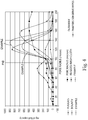
- Pore Volume Distribution as used herein means the distribution of fluid holding void volume as a function of pore radius. The Pore Volume Distribution of a fibrous structure is measured according to the Pore Volume Test Method described herein.
- component or composition levels are in reference to the active level of that component or composition, and are exclusive of impurities, for example, residual solvents or by-products, which may be present in commercially available sources.
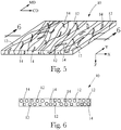
- Figs. 1 and 2 depict one example of a system and process for manufacturing a bonded nonwoven web or other fibrous structure. It will be understood that the features of a bonding pattern described below may be imparted to a nonwoven web manufactured according to a process as depicted in Fig. 1 , but may also be imparted to nonwoven webs manufactured by other systems and/or processes, such as but not limited to those described further below ( e.g ., with reference to Fig. 11 ). In the example depicted in Fig. 1 , one or more layers 100, 101, 102 of filaments may be spun from polymeric resin(s) melted and forced under pressure by extruders through beams of spinnerets 300, 301, 302.
- one or more of the layers such as middle layer 101 may be formed of depositions of natural or synthetic fibers or staple fibers. As they are introduced the filaments and/or fibers may be deposited onto and accumulated on a moving belt 310 to form a batt 104. It will be appreciated that the basis weight, fiber/filament density and/or loft of the batt 104 may be controlled by controlling the rate(s) of deposition of fibers and/or filaments and the speed of the belt 310.
- batt 104 may be conveyed into a compression passage 322 between a pair of rollers 320, 321.
- rollers 320, 321 may be a bonding roller with its cylindrical surface bearing a pattern of radially outermost bonding surfaces 323 and recessed areas 324.
- one of rollers 320, 321 may be an anvil roller having a smooth, featureless cylindrical surface.
- rollers 320, 321 may be heated, or alternatively, energy (such as ultrasonic energy) may be provided at the rollers, that heats the fibers and/or filaments of the batt. Heating energy may be controlled to sufficiently heat the fibers and/or filaments to cause them to partially melt where they are superimposed and compressed beneath the bonding surfaces 323. If polymeric resin(s) forming the fibers and/or filaments are of the same or suitably similar compositions, or are otherwise miscible when melted, thermal fusing and bonding of superimposed fibers and/or filaments may be caused to occur beneath the bonding surfaces 323 in the compression passage 322.
- energy such as ultrasonic energy
- polymeric resins of compositions that differ such that they are immiscible when melted are used to form differing fibers and/or filaments, they may still form bonds as the dissimilar resins are forced to flow together under pressure such that a physically intermingled structure of the immiscible polymers results.
- an adhesive may be introduced at or upstream of rollers 320, 321 such that adhesive bonds between superimposed fibers and/or filaments or fibers beneath the bonding surfaces 323 are formed as the batt passes through the compression passage 322.
- a bonded nonwoven web 105 exits the compression passage 322.
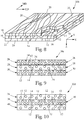
- the nonwoven web will bear a pattern of bonded areas 106 and unbonded areas 107 closely corresponding in configuration to the pattern of bonding surfaces 323 and recessed areas 324 on the bonding roller 320. It will be understood that a pattern of bonded areas 106 may be impressed into a batt to form a bonded nonwoven by more than one bonding roller, i.e ., a series of bonding rollers each impressing a portion of a final combination pattern of bonded areas appearing in the nonwoven web.
- nonwoven web 105 may be gathered on a roll 330 for transportation, storage and later use. Alternatively, the web 105 may be conveyed directly to downstream processing/converting equipment in the same manufacturing line.
- a bonding roller such as roller 320 will have a bonding area. This is the total area of the bonding surfaces 323. Bonding area percentage is the ratio of the total area of the bonding surfaces 323, divided by the sum of the total area of the bonding surfaces 323 plus the total area of the recessed areas ( e.g ., recessed areas 324 in Fig. 2 ) between the bonding surfaces, x 100%.
- the bonding area percentage of the bonding roller be 6 percent to 14 percent, more preferably 7 percent to 13 percent, and even more preferably 8 percent to 12 percent, or even 9 percent to 11 percent.
- a bonding area percentage within one or more of these ranges strikes a favorable balance between imparting a desired level of tensile strength and structural integrity to the nonwoven web, and allowing the web to retain desired levels of loft, liquid absorption capacity and/or uptake and/or permeability, and pliability/tactile softness.
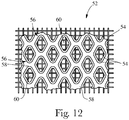
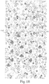
- a bonding pattern may be configured to a pattern of bonded areas having decorative or aesthetically pleasing features. For example, see the pattern depicted in Fig. 14 , with bonded areas 106 in the shapes of fanciful hearts and butterflies, and unbonded areas 107.
- imparting particular attributes to the bonding pattern may improve its effectiveness at imparting strength and structural integrity, preserve or improve softness and absorbency levels, and provide a way to enhance the visual appeal of the pattern, for a given bonding area percentage. Any bonding area is distributed or dispersed across the nonwoven through whatever particular bonding pattern is chosen. However, it has been discovered that a greater dispersion of bonding area enables more visually complex bond pattern designs (for aesthetic purposes), and, as bonding area is dispersed to greater extents, beneficial structural effects are realized. As dispersion of bonding area is increased, the number of potential bonded areas or bond sites is generally increased, while their average size in one or more dimensions (or their average area) is generally decreased.
- the increase in the number of bonded areas or bond sites may substantially improve the web's resistance to separation or peeling of the outer layers from the remainder of the web structure because fine filaments will accumulate at a substantially greater numerical density per unit basis weight of deposition - as compared with coarser fibers such as spunbond filaments - which contributes to the increased number and numerical density of bonded areas or bond sites imparted to the web.
- the increase in the number of bonded sites resulting from greater dispersion may substantially improve the web's resistance to abrasion and/or linting (wherein the fibers in the internal layer are dislodged and escape the web structure).
- fine filaments are filaments having an average diameter from 0.1 to 10 micrometers.
- the dispersion of the bonded area of a nonwoven web may be challenging to characterize, measure, and quantify.
- difficulties lie in attempting to precisely distinguish bonded areas from unbonded areas, particularly at the boundaries therebetween where the fibrous structure makes the boundaries somewhat indistinct visually.
- the bonded area and bond pattern impressed on a nonwoven web generally reflects that pattern(s) of bonding surfaces 324 on the bonding roller(s) used.
- the dispersion of bonded area of the web reflects the dispersion of bonding area among the bonding surfaces 323 of the one or more bonding rollers 320 used.
- the area of the bonding surfaces 323 and the dispersion of bonding area embodied in their design and pattern may be analyzed using the Bonding Pattern Analysis method herein.
- bonding area dispersion may be characterized according to average bonding area dispersion distance. Generally, greater dispersion is reflected in smaller average bonding area dispersion distance. For example, if the same bonding area is dispersed in two regular patterns of circular bonding surfaces, the two patterns differing only by the size and spacing of the individual bonding surfaces, the pattern with the smaller bonding surfaces will have the smaller spacing and the greater number of bonding surfaces, thus have a smaller average bonding area dispersion distance. Generally for any particular bonding pattern and bonding area, regularly arranged or irregularly arranged, smaller bonding surfaces more closely spaced have greater dispersion, and vice versa.
- Increasing dispersion, reflected in limiting average bonding area dispersion distance, provides for greater detail and visual complexity. It is believed that significant structural benefits as described above may be imparted to a nonwoven web using a bonding pattern having an average bonding area dispersion distance no greater than 5.0 mm, more preferably no greater than 4.5 mm, more preferably no greater than 4.0 mm, more preferably no greater than 3.5, and still more preferably no greater than 3.0 mm.
- a bonding pattern having the features described above may be beneficial with a nonwoven web of any particular fiber/filament composition and layering configuration, but may be especially beneficial with a nonwoven web formed according to the description below.
- the bonding pattern may be used to bond filaments of one outer layer to filaments of the other outer layer. This may be particularly beneficial if one or both of the outer layers are formed if fine filaments, wherein a finely dispersed bonding area creates a relatively great number bonded areas among the comparatively numerically dense deposits of fine filaments.
- pattern irregularity is reflected in variation in the pattern with respect to pattern repeat distances in the machine and/or cross directions, and in varying design, spacing and rotational orientations of design elements present in the pattern. Irregularity provides for more interesting visual/aesthetic effects.
- a suitable level of dispersion i.e ., limiting average bonding area dispersion distance
- a high level of visual detail and complexity in addition to structural benefits as described above, may be achieved.
- One way in which the irregularity of a bonding pattern may be characterized lies in a comparison of adjacent 100 mm by 100 mm square samples of the bonding pattern. This sample size may be considered relevant because it is somewhat comparable with the sizes of several types of wipes products.
- a bonding pattern does not include a design element that is substantially repeated on any two adjacent 100 mm x 100 mm square samples of the bonding pattern, the pattern may take on interesting visual variability and complexity. Additional examples of suitable pattern variability are described in co-pending U.S. Pat. App. Ser. No. 13/928,507 .
- a bonding pattern having the features described above may be beneficial with a nonwoven web of any particular fiber/filament composition and layering configuration, but may be especially beneficial with a nonwoven web formed according to the description below.
- a bonding technique is used to impart the pattern, and more particularly, a bonding technique that creates bonded areas that are substantially resistant to bond degradation in the presence of aqueous liquid.
- Such techniques may include, but are not necessarily limited to, bonding with a water-impervious adhesive, thermal bonding, ultrasonic bonding etc. This helps ensure that the structural and visual benefits of the pattern of bonded areas of the web are substantially retained when the nonwoven web material is wetted.
- a fibrous structures as described herein can exhibit a Liquid Absorptive Capacity higher than other known structured and/or textured fibrous structures as measured according to the Liquid Absorptive Capacity Test Method described herein.
- Fig. 3 shows that fibrous structures and/or wipes as described herein may exhibit a distinctive combination of Liquid Absorptive Capacity and Soil Leak Through.
- Fig. 4 shows that fibrous structures and/or wipes as described herein may exhibit distinctive pore volume distributions.
- Fibrous structures as described herein may include a plurality of filaments, a plurality of solid additives, such as fibers, and a mixture of filaments and solid additives.
- Figs. 5 and 6 show schematic representations of an example of a fibrous structure contemplated herein.
- the fibrous structure 10 may be a co-formed fibrous structure.
- the fibrous structure 10 comprises a plurality of filaments 12, such as polypropylene filaments, and a plurality of solid additives, such as wood pulp fibers 14.
- the filaments 12 may be randomly arranged as a result of the process by which they are spun and/or formed into the fibrous structure 10.
- the wood pulp fibers 14, may be randomly dispersed throughout the fibrous structure 10 in the x-y plane.
- the wood pulp fibers 14 may be non-randomly dispersed throughout the fibrous structure in the z-direction. In one example (not shown), the wood pulp fibers 14 are present at a higher concentration on one or more of the exterior, x-y plane surfaces than within the fibrous structure along the z-direction.
- Fig. 7 shows a cross-sectional, SEM microphotograph of another example of a fibrous structure 10a as contemplated herein, including a non-random, repeating pattern of microregions 15a and 15b.
- the microregion 15a (typically referred to as a "pillow") exhibits a different value of a common intensive property than microregion 15b (typically referred to as a "knuckle").
- the microregion 15b is a continuous or semi-continuous network and the microregion 15a are discrete regions within the continuous or semi-continuous network.
- the common intensive property may be caliper.
- the common intensive property may be density.
- a fibrous structure contemplated herein is a layered fibrous structure 10b.
- the layered fibrous structure 10b comprises a first layer 16 comprising a plurality of filaments 12, such as polypropylene filaments, and a plurality of solid additives, in this example, wood pulp fibers 14.
- the layered fibrous structure 10b further comprises a second layer 18 comprising a plurality of filaments 20, such as polypropylene filaments.
- the first and second layers 16, 18, respectively are sharply defined zones of concentration of the filaments and/or solid additives.
- the plurality of filaments 20 may be deposited directly onto a surface of the first layer 16 to form a layered fibrous structure that comprises the first and second layers 16, 18, respectively.
- the layered fibrous structure 10b may comprise a third layer 22, as shown in Fig. 8 .
- the third layer 22 may comprise a plurality of filaments 24, which may be the same or different from the filaments 20 and/or 16 in the second 18 and/or first 16 layers.
- the first layer 16 is positioned, for example sandwiched, between the second layer 18 and the third layer 22.
- the plurality of filaments 24 may be deposited directly onto a surface of the first layer 16, opposite from the second layer, to form the layered fibrous structure 10b that comprises the first, second and third layers 16, 18, 22, respectively.
- Fig. 9 is a cross-sectional schematic representation of another example of a fibrous structure contemplated herein, which includes a layered fibrous structure 10c.
- the layered fibrous structure 10c includes a first layer 26, a second layer 28 and optionally a third layer 30.
- the first layer 26 includes a plurality of filaments 12, such as polypropylene filaments, and a plurality of solid additives, such as wood pulp fibers 14.
- the second layer 28 may include any suitable filaments, solid additives and/or polymeric films.
- the second layer 28 includes a plurality of filaments 34.
- the filaments 34 includes a polymer selected from the group consisting of: polysaccharides, polysaccharide derivatives, polyvinylalcohol, polyvinylalcohol derivatives and mixtures thereof.
- a fibrous structure may include two outer layers consisting of 100% by weight filaments and an inner layer consisting of 100% by weight fibers.
- the material forming layers 26, 28 and 30 may be in the form of plies wherein two or more of the plies may be combined to form a fibrous structure.
- the plies may be bonded together, such as by thermal bonding and/or adhesive bonding, to form a multi-ply fibrous structure.
- the fibrous structure 10d may comprise two or more plies, wherein one ply 36 includes any suitable fibrous structure described herein, for example fibrous structure 10 as shown and described in Figs. 5 and 6 and another ply 38 including any suitable fibrous structure, for example a fibrous structure including filaments 12, such as polypropylene filaments.
- the fibrous structure of ply 38 may be in the form of a net and/or mesh and/or other structure that includes pores that expose one or more portions of the fibrous structure 10d to an external environment and/or at least to liquids that may come into contact, at least initially, with the fibrous structure of ply 38.
- the fibrous structure 10d may further comprise ply 40.
- Ply 40 may comprise a fibrous structure comprising filaments 12, such as polypropylene filaments, and may be the same or different from the fibrous structure of ply 38.
- Two or more of the plies 36, 38 and 40 may be bonded together, such as by thermal bonding and/or adhesive bonding, to form a multi-ply fibrous structure. After a bonding operation, especially a thermal bonding operation, it may be difficult to distinguish the plies of the fibrous structure 10d and the fibrous structure 10d may visually and/or physically be a similar to a layered fibrous structure in that one would have difficulty separating the once individual plies from each other.
- ply 36 may comprise a fibrous structure that exhibits a basis weight of at least about 15 g/m 2 and/or at least about 20 g/m 2 and/or at least about 25 g/m 2 and/or at least about 30 g/m 2 up to about 120 g/m 2 and/or 100 g/m 2 and/or 80 g/m 2 and/or 60 g/m 2 and the plies 38 and 42, when present, independently and individually, may comprise fibrous structures that exhibit basis weights of less than about 10 g/m 2 and/or less than about 7 g/m 2 and/or less than about 5 g/m 2 and/or less than about 3 g/m 2 and/or less than about 2 g/m 2 and/or to about 0 g/m 2 and/or 0.5 g/m 2 .
- Plies 38 and 40 when present, may help retain the solid additives, in this case the wood pulp fibers 14, on and/or within the fibrous structure of ply 36 thus reducing lint and/or dust (as compared to a single-ply fibrous structure comprising the fibrous structure of ply 36 without the plies 38 and 40) resulting from the wood pulp fibers 14 becoming free from the fibrous structure of ply 36.
- Fibrous structures as contemplated herein may include any suitable amount of filaments and any suitable amount of solid additives.
- the fibrous structures may comprise from about 10% to about 70% and/or from about 20% to about 60% and/or from about 30% to about 50% by dry weight of the fibrous structure of filaments and from about 90% to about 30% and/or from about 80% to about 40% and/or from about 70% to about 50% by dry weight of the fibrous structure of solid additives, such as wood pulp fibers.
- the fibrous structures include filaments.
- Filaments and solid additives may be present at weight ratios of filaments to solid additives of from at least about 1:1 and/or at least about 1:1.5 and/or at least about 1:2 and/or at least about 1:2.5 and/or at least about 1:3 and/or at least about 1:4 and/or at least about 1:5 and/or at least about 1:7 and/or at least about 1:10.
- Fibrous structures and/or any sanitary tissue products comprising such fibrous structures may be subjected to any post-processing operations such as embossing operations, printing operations, tuft-generating operations, thermal bonding operations, ultrasonic bonding operations, perforating operations, surface treatment operations such as application of lotions, silicones and/or other materials, folding, and mixtures thereof.
- post-processing operations such as embossing operations, printing operations, tuft-generating operations, thermal bonding operations, ultrasonic bonding operations, perforating operations, surface treatment operations such as application of lotions, silicones and/or other materials, folding, and mixtures thereof.
- Non-limiting examples of suitable polypropylenes for making the filaments are commercially available from Lyondell-Basell and Exxon-Mobil.
- Any hydrophobic or non-hydrophilic materials within the fibrous structure, such as polypropylene filaments, may be surface treated and/or melt treated with a hydrophilic modifier.
- surface treating hydrophilic modifiers include surfactants, such as Triton X-100.
- melt treating hydrophilic modifiers that are added to the melt, such as the polypropylene melt, prior to spinning filaments include hydrophilic modifying melt additives such as VW351 and/or S-1416 commercially available from Polyvel, Inc. and Irgasurf commercially available from Ciba.
- the hydrophilic modifier may be associated with the hydrophobic or non-hydrophilic material at any suitable level known in the art.
- the hydrophilic modifier is associated with the hydrophobic or non-hydrophilic material at a level of less than about 20% and/or less than about 15% and/or less than about 10% and/or less than about 5% and/or less than about 3% to about 0% by dry weight of the hydrophobic or non-hydrophilic material.
- Fibrous structures contemplated herein may include optional additives, each, when present, at individual levels of from about 0% and/or from about 0.01 % and/or from about 0.1 % and/or from about 1% and/or from about 2% to about 95% and/or to about 80% and/or to about 50% and/or to about 30% and/or to about 20% by dry weight of the fibrous structure.
- Non-limiting examples of optional additives include permanent wet strength agents, temporary wet strength agents, dry strength agents such as carboxymethylcellulose and/or starch, softening agents, lint reducing agents, opacity increasing agents, wetting agents, odor absorbing agents, perfumes, temperature indicating agents, color agents, dyes, osmotic materials, microbial growth detection agents, antibacterial agents and mixtures thereof.
- a fibrous structure contemplated herein may itself be a sanitary tissue product. It may be wound about a core to form a roll. It may be combined with one or more other fibrous structures as a ply to form a multi-ply web product. In one example, a co-formed fibrous structure as described herein may be wound about a core to form a roll of co-formed sanitary tissue product. Rolls of sanitary tissue products may also be coreless.
- Fibrous structures as contemplated herein may exhibit a Liquid Absorptive Capacity of at least 2.5 g/g and/or at least 4.0 g/g and/or at least 7 g/g and/or at least 12 g/g and/or at least 13 g/g and/or at least 13.5 g/g and/or to about 30.0 g/g and/or to about 20 g/g and/or to about 15.0 g/g as measured according to the Liquid Absorptive Capacity Test Method described herein.
- a fibrous structure as described above, may be utilized to form a wipe.
- wipe may be a general term to describe a piece of material, generally non-woven material, used in cleansing hard surfaces, food, inanimate objects, toys and body parts.
- many currently available wipes may be intended for the cleansing of the perianal area after defecation.
- Other wipes may be available for the cleansing of the face or other body parts.
- Multiple wipes may be attached together by any suitable method to form a mitt.
- the material from which a wipe is made should be strong enough to resist tearing during normal use, yet still provide softness to the user's skin, such as a child's tender skin. Additionally, the material should be at least capable of retaining its form for the duration of the user's cleansing experience.
- Wipes may be generally of sufficient dimension to allow for convenient handling.
- the wipe may be cut and/or folded to such dimensions as part of the manufacturing process.
- the wipe may be cut into individual portions so as to provide separate wipes which are often stacked and interleaved in consumer packaging.
- the wipes may be in a web form where the web has been slit and folded to a predetermined width and provided with means (e.g., perforations) to allow individual wipes to be separated from the web by a user.
- an individual wipe may have a length between about 100 mm and about 250 mm and a width between about 140 mm and about 250 mm.
- the wipe may be about 200 mm long and about 180 mm wide and/or about 180 mm long and about 180 mm wide and/or about 170 mm long and about 180 mm wide and/or about 160 mm long and about 175 mm wide.
- the material of the wipe may generally be soft and flexible, potentially having a structured surface to enhance its cleaning performance.
- the wipe may be a laminate of two or more materials. Commercially available laminates, or purposely built laminates are contemplated. The laminated materials may be joined or bonded together in any suitable fashion, such as, but not limited to, ultrasonic bonding, adhesive, glue, fusion bonding, heat bonding, thermal bonding and combinations thereof.
- the wipe may be a laminate including one or more layers of nonwoven web materials and one or more layers of film. Examples of such optional films, include, but are not limited to, polyolefin films, such as, polyethylene film.
- An illustrative, but non-limiting example of a nonwoven web material which is a laminate is a laminate of a 16 gsm nonwoven polypropylene and a 0.8 mm 20 gsm polyethylene film.
- Wipes may also be treated to improve the softness and texture thereof by processes such as hydroentanglement or spunlacing.
- the wipes may be subjected to various treatments, such as, but not limited to, physical treatment, such as ring rolling, as described in U.S. Patent No. 5,143,679 ; structural elongation, as described in U.S. Patent No. 5,518,801 ; consolidation, as described in U.S. Patent Nos. 5,914,084 , 6,114,263 , 6,129,801 and 6,383,431 ; stretch aperturing, as described in U.S. Patent Nos. 5,628,097 , 5,658,639 and 5,916,661 ; differential elongation, as described in WO Publication No.
- a wipe may be manufactured to have a basis weight of at least about 30 grams/m 2 and/or at least about 35 grams/m 2 and/or at least about 40 grams/m 2 .
- a wipe may be manufactured to have a basis weight of at least about 45 grams/m 2 .
- the wipe basis weight may be less than about 100 grams/m 2 .
- wipes may have a basis weight between about 45 grams/m 2 and about 75 grams/m 2 , and in yet another embodiment a basis weight between about 45 grams/m 2 and about 65 grams/m 2 .
- a wipe may be manufactured to have a macroscopic surface that is substantially flat.
- the wipe may be manufactured to have a surface that includes macroscopically visible details formed by raised and/or lowered portions. These can be in the form of logos, indicia, trademarks, geometric patterns, images of the surfaces that the substrate is intended to clean (i.e., infant's body, face, etc.). They may be randomly arranged on the surface of the wipe or be in a repetitive pattern of some form. They may be imparted by embossing, bonding or a combination thereof.
- a wipe as contemplated herein may be manufactured so as to be biodegradable.
- a wipe can be made from a biodegradable material such as a polyesteramide, or high wet strength cellulose.
- a fibrous structure contemplated herein is a pre-moistened wipe, such as a baby wipe.
- a plurality of pre-moistened wipes may be stacked one on top of the other and may be contained in a container, such as a plastic tub or a film wrapper.
- a stack of pre-moistened wipes (typically but not necessarily about 40 to 80 wipes/stack) may exhibit a height of from about 50 to about 300 mm and/or from about 75 to about 125 mm.
- Pre-moistened wipes may be moistened with an aqueous liquid composition, such as a lotion.
- Pre-moistened wipes may be stored long term in a stack in a liquid impervious container or film pouch without all of the lotion draining from the top of the stack to the bottom of the stack.
- Pre-moistened wipes may be manufactured as described herein to exhibit a Liquid Absorptive Capacity of at least 2.5 g/g and/or at least 4.0 g/g and/or at least 7 g/g and/or at least 12 g/g and/or at least 13 g/g and/or at least 13.5 g/g and/or to about 30.0 g/g and/or to about 20 g/g and/or to about 15.0 g/g as measured according to the Liquid Absorptive Capacity Test Method described herein.
- pre-moistened wipes may be manufactured as described herein to exhibit a saturation loading (g liquid composition to g of dry wipe) of from about 1.5 to about 6.0 g/g.
- the liquid composition may exhibit a surface tension of from about 20 to about 35 and/or from about 28 to about 32 dynes/cm.
- Pre-moistened wipes may exhibit a dynamic absorption time (DAT) from about 0.01 to about 0.4 and/or from about 0.01 to about 0.2 and/or from about 0.03 to about 0.1 seconds as measured according to the Dynamic Absorption Time Test Method described herein.
- DAT dynamic absorption time
- Pre-moistened wipes may be disposed in a stack that exhibits a height of from about 50 to about 300 mm and/or from about 75 to about 200 mm and/or from about 75 to about 125 mm, wherein the stack exhibits a saturation gradient index of from about 1.0 to about 2.0 and/or from about 1.0 to about 1.7 and/or from about 1.0 to about 1.5.
- Fibrous structures or wipes contemplated herein may be saturation loaded with a liquid composition to form a pre-moistened fibrous structure or wipe.
- the loading may occur individually, or after the fibrous structures or wipes are place in a stack, such as within a liquid impervious container or packet.
- the pre-moistened wipes may be saturation loaded with from about 1.5 g to about 6.0 g and/or from about 2.5 g to about 4.0 g of liquid composition per g of wipe.
- Fibrous structures contemplated herein may be placed in the interior of a container, which may be liquid impervious, such as a lidded plastic tub or a sealed package formed of flexible polymeric film, for storage and eventual sale to the consumer.
- the wipes may be folded and stacked.
- the wipes may be folded in any of various known folding patterns, such as C-folding, Z-folding and quarter-folding. Use of a Z-fold pattern may enable a folded stack of wipes to be interleaved with overlapping portions.
- a supply of wipes may consist of a continuous strip of material which has cross-wise perforations between each wipe, wherein wipes may be successively torn away along the perforations.
- the continuous strip may be folded accordion-fashion to create a stack, or may be wound into a roll.
- the folded stack or roll may be disposed in a container, which may be liquid impervious, and the container may be provided with a dispensing opening and a closing lid, flap, or resealable opening mechanism.
- Fibrous structures or wipes as contemplated herein may further include designs printed thereon, which may provide aesthetic appeal.
- designs printed thereon include figures, patterns, alphanumeric characters, pictures and combinations thereof.
- Table 1 sets forth properties of known and/or commercially available fibrous structures and examples of fibrous structures as contemplated herein.
- Table 1 Contains Filament Basis Wt. Liquid Abs. Capacity Lotion Release (g) Soil Leak Through SGI CD Wet Initial Tensile Strength 43% or more of pores between 91 and 140 ⁇ m 30% or more of pores between 121 and 200 ⁇ m [gsm] [g/g] [g] Lr Value [N/5cm]
- Example Yes 65.0 16.0 0.355 0.9 1.21 6.0
- Table 2 sets forth the average pore volume distributions of known and/or commercially available fibrous structures and examples of fibrous structures as contemplated herein.
- FIG. 11 A non-limiting example of another method for making a fibrous structure suitable for purposes described herein is represented in Fig. 11 .
- the method shown in Fig. 11 includes the step of mixing a plurality of solid additives 14 with a plurality of filaments 12.
- the solid additives 14 are wood pulp fibers, such as SSK fibers and/or Eucalytpus fibers
- the filaments 12 are polypropylene filaments.
- the solid additives 14 may be combined with the filaments 12, such as by being delivered to a stream of filaments 12 from a hammermill 42 via a solid additive spreader 44 to form a mixture of filaments 12 and solid additives 14.
- the filaments 12 may be created by meltblowing from a meltblow die 46.
- the mixture of solid additives 14 and filaments 12 are collected on a collection device, such as a belt 48 to form a fibrous structure 50.
- the collection device may be a patterned and/or molded belt that results in the fibrous structure exhibiting a surface pattern, such as a non-random, repeating pattern of microregions.
- the molded belt may have a three-dimensional pattern on it that gets imparted to the fibrous structure 50 during the process.
- the patterned belt 52 as shown in Fig. 12 , may comprise a reinforcing structure, such as a fabric 54, upon which a polymer resin 56 is applied in a pattern.
- the pattern may comprise a continuous or semi-continuous network 58 of the polymer resin 56 within which one or more discrete conduits 60 are arranged.
- the fibrous structures may be made using a die comprising at least one filament-forming hole, and/or 2 or more and/or 3 or more rows of filament-forming holes from which filaments are spun. At least one row of holes contains 2 or more and/or 3 or more and/or 10 or more filament-forming holes.
- the die comprises fluid-releasing holes, such as gas-releasing holes, in one example air-releasing holes, that provide attenuation to the filaments formed from the filament-forming holes.
- One or more fluid-releasing holes may be associated with a filament-forming hole such that the fluid exiting the fluid-releasing hole is parallel or substantially parallel (rather than angled like a knife-edge die) to an exterior surface of a filament exiting the filament-forming hole.
- the fluid exiting the fluid-releasing hole contacts the exterior surface of a filament formed from a filament-forming hole at an angle of less than 30° and/or less than 20° and/or less than 10° and/or less than 5° and/or about 0°.
- One or more fluid releasing holes may be arranged around a filament-forming hole.
- one or more fluid-releasing holes are associated with a single filament-forming hole such that the fluid exiting the one or more fluid releasing holes contacts the exterior surface of a single filament formed from the single filament-forming hole.
- the fluid-releasing hole permits a fluid, such as a gas, for example air, to contact the exterior surface of a filament formed from a filament-forming hole rather than contacting an inner surface of a filament, such as what happens when a hollow filament is formed.
- a fluid such as a gas, for example air
- the die may have a filament-forming hole positioned within a fluid-releasing hole.
- the fluid-releasing hole 62 may be concentrically or substantially concentrically positioned around a filament-forming hole 64 such as is shown in Fig. 13 .
- the fibrous structure 50 may be calendered, for example, while the fibrous structure is still on the collection device.
- the fibrous structure 50 may be subjected to post-processing operations such as embossing, thermal bonding (such as described above), tuft-generating operations, moisture-imparting operations, and surface treating operations to form a finished fibrous structure.
- post-processing operations such as embossing, thermal bonding (such as described above), tuft-generating operations, moisture-imparting operations, and surface treating operations to form a finished fibrous structure.
- a surface treating operation that the fibrous structure may be subjected to is the surface application of an elastomeric binder, such as ethylene vinyl acetate (EVA), latexes, and other elastomeric binders.
- EVA ethylene vinyl acetate
- Such an elastomeric binder may aid in reducing the lint created from the fibrous structure during use by consumers.
- the elastomeric binder may be applied to one or more surfaces of the fibrous structure in a pattern, especially a non-random, repeating pattern of microregions, or in a manner that covers or substantially covers the entire surface(s) of the fibrous structure.
- the fibrous structure 50 and/or the finished fibrous structure may be combined with one or more other fibrous structures.
- another fibrous structure such as a filament-containing fibrous structure, such as a polypropylene filament fibrous structure may be associated with a surface of the fibrous structure 50 and/or the finished fibrous structure.
- the polypropylene filament fibrous structure may be formed by meltblowing polypropylene filaments (filaments that comprise a second polymer that may be the same or different from the polymer of the filaments in the fibrous structure 50) onto a surface of the fibrous structure 50 and/or finished fibrous structure.
- the polypropylene filament fibrous structure may be formed by meltblowing filaments comprising a second polymer that may be the same or different from the polymer of the filaments in the fibrous structure 50 onto a collection device to form the polypropylene filament fibrous structure.
- the polypropylene filament fibrous structure may then be combined with the fibrous structure 50 or the finished fibrous structure to make a two-ply fibrous structure - three-ply if the fibrous structure 50 or the finished fibrous structure is positioned between two plies of the polypropylene filament fibrous structure like that shown in Fig. 8 for example.
- the polypropylene filament fibrous structure may be thermally bonded to the fibrous structure 50 or the finished fibrous structure via a thermal bonding operation.
- the fibrous structure 50 and/or finished fibrous structure may be combined with a filament-containing fibrous structure such that the filament-containing fibrous structure, such as a polysaccharide filament fibrous structure, such as a starch filament fibrous structure, is positioned between two fibrous structures 50 or two finished fibrous structures like that shown in Fig. 10 for example.
- a filament-containing fibrous structure such as a polysaccharide filament fibrous structure, such as a starch filament fibrous structure
- the method for making a fibrous structure as contemplated herein may include the step of combining a plurality of filaments and optionally, a plurality of solid additives to form a fibrous structure that exhibits the properties of fibrous structures contemplated herein.
- the filaments may include thermoplastic filaments.
- the filaments may include polypropylene filaments.
- the filaments may include natural polymer filaments.
- the method may further include subjecting the fibrous structure to one or more processing operations, such as calendaring the fibrous structure.
- the method may include the step of depositing the filaments onto a patterned belt that creates a non-random, repeating pattern of micro regions.
- two plies of fibrous structure 50 including a non-random, repeating pattern of microregions may be associated with one another such that protruding microregions, such as pillows, face inward into the two-ply fibrous structure formed.
- the process for making fibrous structure 50 may be close coupled (where the fibrous structure is convolutedly wound into a roll prior to proceeding to a converting operation) or directly coupled (where the fibrous structure is not convolutedly wound into a roll prior to proceeding to a converting operation) with a converting operation to emboss, print, deform, surface treat, thermal bond, cut, stack or other post-forming operation known to those in the art.
- direct coupling means that the fibrous structure 50 can proceed directly into a converting operation rather than, for example, being convolutedly wound into a roll and then unwound to proceed through a converting operation.
- the fibrous structure may be embossed, cut into sheets, and collected in stacks of fibrous structures such as wipes and/or wet wipes.
- the process suitable for purposes herein may include preparing individual rolls and/or sheets and/or stacks of sheets of fibrous structure and/or sanitary tissue product comprising such fibrous structure(s) that are suitable for consumer use.
- a 20%:27.5%47.5%:5% blend of Lyondell-Basell PH835 polypropylene : Lyondell-Basell Metocene MF650W polypropylene : Exxon-Mobil PP3546 polypropylene : Polyvel S-1416 wetting agent is dry blended, to form a melt blend.
- the melt blend is heated to 475°F through a melt extruder.
- the solid additive spreader turns the pulp fibers and distributes the pulp fibers in the cross-direction such that the pulp fibers are injected into the meltblown filaments in a perpendicular fashion (with respect to the flow of the meltblown filaments) through a 4 inch x 15 inch cross-direction (CD) slot.
- a forming box surrounds the area where the meltblown filaments and pulp fibers are commingled. This forming box is designed to reduce the amount of air allowed to enter or escape from this commingling area; however, there is an additional 4 inch x 15 inch spreader opposite the solid additive spreader designed to add cooling air. Approximately 1000 SCFM of air at approximately 80°F is added through this additional spreader.
- the fibrous structure formed by this process comprises about 75% by dry fibrous structure weight of pulp and about 25% by dry fibrous structure weight of meltblown filaments.
- meltblown layer of the meltblown filaments can be added to one or both sides of the above formed fibrous structure.
- This addition of the meltblown layer can help reduce the lint created from the fibrous structure during use by consumers and is preferably performed prior to any thermal bonding operation of the fibrous structure.
- the meltblown filaments for the exterior layers can be the same or different than the meltblown filaments used on the opposite layer or in the center layer(s).
- the fibrous structure may be convolutedly wound to form a roll of fibrous structure.
- the end edges of the roll of fibrous structure may be contacted with a material to create bond regions.
- a 20%:27.5%47.5%:5% blend of Lyondell-Basell PH835 polypropylene : Lyondell-Basell Metocene MF650W polypropylene : Exxon-Mobil PP3546 polypropylene : Polyvel S-1416 wetting agent is dry blended, to form a melt blend.
- the melt blend is heated to about 405°F through a melt extruder.
- the solid additive spreaders turns the pulp fibers and distributes the pulp fibers in the cross-direction such that the pulp fibers are injected into the meltblown filaments in a perpendicular fashion (with respect to the flow of the filaments) through two 4 inch x 15 inch cross-direction (CD) slots.
- a forming box surrounds the area where the meltblown filaments and pulp fibers are commingled. This forming box is designed to reduce the amount of air allowed to enter or escape from this commingling area.
- the two slots are oriented opposite of one another on opposite sides of the meltblown filament spinnerette.
- a forming vacuum pulls air through a collection device, such as a non-patterned forming belt or through-air-drying fabric, thus collecting the commingled meltblown filaments and pulp fibers to form a fibrous structure.
- the fibrous structure formed by this process comprises about 80% by dry fibrous structure weight of pulp and about 20% by dry fibrous structure weight of meltblown filaments.
- meltblown layer of the meltblown filaments can be added to one or both sides of the above formed fibrous structure.
- This addition of the meltblown layer can help reduce the lint created from the fibrous structure during use by consumers and is preferably performed prior to any thermal bonding operation of the fibrous structure.
- the meltblown filaments for the exterior layers can be the same or different than the meltblown filaments used on the opposite layer or in the center layer(s).
- the fibrous structure may be convolutedly wound to form a roll of fibrous structure.
- the end edges of the roll of fibrous structure may be contacted with a material to create bond regions.
- a pre-moistened wipe contemplated herein may be prepared as follows.
- a fibrous structure of about 44 g/m 2 that comprises a thermal bonded pattern as shown in Fig. 14 is saturation loaded with a liquid composition formulated as described herein to an average saturation loading of about 358% of the basis weight of the wipe.
- the wipes are then Z-folded and placed in a stack to a height of about 82 mm as shown in Fig. 15 .
- a pre-moistened wipe contemplated herein may be prepared as follows.
- a fibrous structure of about 61 g/m 2 that comprises a thermal bonded pattern as shown in Fig. 14 is saturation loaded with a liquid composition as described herein to an average saturation loading of about 347% of the basis weight of the wipe.
- the wipes are then Z-folded and placed in a stack to a height of about 82 mm as shown in Fig. 15 .
- a pre-moistened wipe contemplated herein may be prepared as follows.
- a fibrous structure generally made as described above in the second non-limiting process example exhibits a basis weight of about 65 g/m 2 and comprises a thermal bond pattern as shown in Fig. 14 is saturation loaded with a liquid composition formulated as described herein to an average saturation loading of about 347% of the basis weight of the wipe.
- the wipes are then Z-folded and placed in a stack to a height of about 82 mm as shown in Fig. 15 .
- a bonding pattern according to the image shown in Fig. 16 is used in current PAMPERS brand baby wipes.
- the pattern was analyzed according to the Bond Pattern Analysis method herein. Analysis revealed that the pattern has a bonding area of 6.3 percent and an average bonding area dispersion distance of 5.5 mm.
- a bonding pattern according to the image shown in Fig. 17 was analyzed according to the Bond Pattern Analysis method herein. Analysis revealed that the pattern has a bonding area of 9.9 percent and an average bonding area dispersion distance 1.8 mm. It can be seen that the image of Fig. 17 has much greater detail and complexity that the image of Fig. 16 . It is believed that, when a bonding pattern have a bonding area dispersion such as as shown in Fig. 17 is used to bond a multilayer nonwoven web having outer layers of filaments as described herein, the web will exhibit substantially improved resistance to peeling away of the outer layers, and resistance to linting, as compared to the same web bonded with the pattern of Fig. 16 . At the same time, it is believed that desirable pliability and liquid uptake and/or absorption characteristics of the web are retained.
- FIG. 18 Another example of a bonding pattern conforming to the description of a highly dispersed bond area herein is depicted in Fig. 18 .
- Figs. 17 and 18 are images of an entire pattern to be reflected in the entire acting roller surface area of a bonding roller.
- the machine direction is vertical with respect to these figures.
- the top and bottom edges shown in the images would be uninterruptedly joined about the circumference of the actual bonding roller such that the design elements are continuous.
- the fibrous structure or wipe comprises a liquid composition such that the fibrous structure or wipe exhibits a moisture level of about 100% or greater by weight of the fibrous structure or wipe, then the following pre-conditioning procedure needs to be performed on the fibrous structure or wipe before testing.
- the fibrous structure or wipe comprises a liquid composition such that the fibrous structure or wipe exhibits a moisture level of less than about 100% by weight but greater than about 10% by weight of the fibrous structure or wipe, dry the fibrous structure or wipe in an oven at 85°C until the fibrous structure or wipe contains less than 3% moisture by weight of the fibrous structure or wipe prior to completing the dry test methods.
- a fibrous structure or wipe comprising a moisture level of about 100% or greater by weight of the fibrous structure or wipe use the following procedure.
- Fully saturate the fibrous structure or wipe by immersing the fibrous structure or wipe sequentially in 2 L of fresh distilled water in each of 5 buckets, where the water is at a temperature of 23°C ⁇ 2.2°C.
- the fibrous structure or wipe After the fibrous structure or wipe exhibits less than 3% moisture, remove from the oven and allow the fibrous structure or wipe to equilibrate to about 23°C ⁇ 2.2°C and a relative humidity of 50% ⁇ 10% for 24 hours prior to the testing. Care needs to be taken to ensure that the fibrous structure and/or wipe is not compressed.
- the fibrous structure or wipe comprises a moisture level of 0% to less than about 100% by weight of the fibrous structure or wipe, then the following pre-conditioning procedure needs to be performed on the fibrous structure or wipe prior to testing. If the fibrous structure or wipe comprises a moisture level of about 100% or greater, then the following pre-conditioning procedure is not performed on the fibrous structure or wipe.
- a fibrous structure or wipe comprising a moisture level of 0% to less than about 100% by weight of the fibrous structure or wipe
- the fibrous structure or wipe After the fibrous structure or wipe is saturation loaded to a 3.5 g/g saturation loading, allow the fibrous structure or wipe to equilibrate to about 23°C ⁇ 2.2°C and a relative humidity of 50% ⁇ 10% for 24 hours prior to the testing. Care needs to be taken to ensure that the fibrous structure and/or wipe is not compressed.
- the following method which is modeled after EDANA 10.4-02, is suitable to measure the Liquid Absorptive Capacity of any fibrous structure or wipe.
- Pore Volume Distribution measurements are made on a TRI/Autoporosimeter (TRI/Princelon Inc. of Princeton, NJ).
- the TRI/Autoporosimeter is an automated computer-controlled instrument for measuring pore volume distributions in porous materials (e.g., the volumes of different size pores within the range from 2.5 to 1000 ⁇ m effective pore radii).
- Complimentary Automated Instrument Software, Release 2000.1, and Data Treatment Software, Release 2000.1 is used to capture, analyze and output the data. More information on the TRI/Autoporosimeter, its operation and data treatments can be found in The Journal of Colloid and Interface Science 162 (1994), pgs 163-170 ,
- determining Pore Volume Distribution involves recording the increment of liquid that enters a porous material as the surrounding air pressure changes.
- a sample in the test chamber is exposed to precisely controlled changes in air pressure.
- the size (radius) of the largest pore able to hold liquid is a function of the air pressure.
- different size pore groups drain (absorb) liquid.
- the pore volume of each group is equal to this amount of liquid, as measured by the instrument at the corresponding pressure.
- pores are thought of in terms such as voids, holes or conduits in a porous material. It is important to note that this method uses the above equation to calculate effective pore radii based on the constants and equipment controlled pressures. The above equation assumes uniform cylindrical pores. Usually, the pores in natural and manufactured porous materials are not perfectly cylindrical, nor all uniform. Therefore, the effective radii reported here may not equate exactly to measurements of void dimensions obtained by other methods such as microscopy. However, these measurements do provide an accepted means to characterize relative differences in void structure between materials.
- the equipment operates by changing the test chamber air pressure in user-specified increments, either by decreasing pressure (increasing pore size) to absorb liquid, or increasing pressure (decreasing pore size) to drain liquid.
- the liquid volume absorbed at each pressure increment is the cumulative volume for the group of all pores between the preceding pressure setting and the current setting.
- the liquid is a 0.2 weight % solution of octylphenoxy polyethoxy ethanol (Triton X-100 from Union Carbide Chemical and Plastics Co. of Danbury, CT.) in 99.8 weight % distilled water (specific gravity of solution is about 1.0).
- a 0.22 ⁇ m Millipore Glass Filter (Millipore Corporation of Bedford, MA; Catalog # GSWP09025) is employed on the test chamber's porous plate.
- a plexiglass plate weighing about 24 g (supplied with the instrument) is placed on the sample to ensure the sample rests flat on the Millipore Filter. No additional weight is placed on the sample.
- the sequence of pore sizes (pressures) for this application is as follows (effective pore radius in ⁇ m): 2.5, 5, 10, 15, 20, 30, 40, 50, 60, 70, 80, 90, 100, 120, 140, 160, 180, 200, 225, 250, 275, 300, 350, 400, 500, 600, 800, 1000.
- This sequence starts with the fibrous structure or wipe sample dry and saturates it as the pore settings increase (typically referred to with respect to the procedure and instrument as the 1 st absorption).
- a blank condition (no sample between a plexiglass plate and Millipore Filter) is run to account for any surface and/or edge effects within the test chamber. Any pore volume measured for this blank condition is subtracted from the applicable pore grouping of the fibrous structure or wipe sample being tested. If upon subtracting the blank condition the result is 0 or negative then report a 0 for that pore range.
- This data treatment can be accomplished manually or with the available TRI/Autoporosimeter Data Treatment Software, Release 2000.1.
- Percent (%) Total Pore Volume is a percentage calculated by taking the volume of fluid in the specific pore radii range divided by the Total Pore Volume.
- the TRI/Autoporosimeter outputs the volume of fluid within a range of pore radii.
- the first data obtained is for the "5.0 micron" pore radii which includes fluid absorbed between the pore sizes of 2.5 to 5.0 micron radius.
- the next data obtained is for "10 micron" pore radii, which includes fluid absorbed between the 5.0 to 10 micron radii, and so on.
- % Total Pore Volume 91-140 micron pore radii (volume of fluid between 91-140 micron pore radii) / Total Pore Volume.
- Total Pore Volume is the sum of all volumes of fluid between 2.5 micron and 1000 micron pore radii.
- Basis weight is measured prior to the application of any end-use lotion, cleaning solution, or other liquid composition, etc. to the fibrous structure or wipe, and follows a modified EDANA 40.3-90 (February 1996) method as described herein below.
- DAT provides a measure of the ability of the fibrous structure or wipe to absorb a test liquid and the time it takes for the test liquid to be absorbed by the fibrous structure or wipe, which is in turn used as a measure of how well a fibrous structure or wipe will absorb liquid into the fibrous structure or wipe.
- the DAT test method measures the dimensions of a drop of a liquid composition, in this case a drop of a lotion, from the moment it is in contact with a fibrous structure or wipe to when the drop is absorbed by the fibrous structure or wipe.
- the method also measures the rate of change of the dimensions of the drop with respect to time. Fibrous structures or wipes characterized by low DAT and low initial contact angle values may be more absorbent than those characterized by higher DAT and/or higher initial contact angle values.
- DAT Fibro 1100 Dynamic Absorbency Test (DAT) measurements of a fibrous structure or wipe are made utilizing a Thwing Albert DAT Fibro 1100 (Thwing Albert, PA).
- the DAT Fibro 1100 is an automated computer-controlled instrument for measuring contact angle of a drop of a liquid composition on porous materials and the time it takes for the drop of a liquid composition to absorb into the fibrous structure or wipe.
- Contact angle refers to the angle formed by the fibrous structure or wipe and the tangent to the surface of the liquid composition drop in contact with the fibrous structure or wipe. More information on absorbency of sheet materials using an automated contact angle tester can be found in ASTM D 5725-95.
- the DAT contact angle measurements provide a means that is used in the art to characterize relative differences in absorbent properties of materials.
- the equipment operates by controlling the volume and the ejection pulse of a small drop of a liquid composition discharged directly onto the surface of a fibrous structure or wipe.
- the height, base and angle produced as the liquid composition drop settles and becomes absorbed into the fibrous structure or wipe are determined based on an internal calibrated gray scale.
- a DAT Fibro 1100 series model (high speed camera resolution for porous absorbent paper substrates) is calibrated according to the manufacturer's instructions and using a 0.292 calibration sled.
- the instrument is set to discharge a 4 microliter ( ⁇ L) drop of a liquid composition, a stroke pulse of 8, canula tip of 340, drop bottom of 208, and paper position of 134.
- the fibrous structure or wipe samples to be tested are cut to approximately 0.5 inches in length and not exceeding the width of the sample sled associated with the testing equipment.
- the fibrous structure or wipe samples are cut along the MD direction of the fibrous structure or wipe to minimize neckdown and structural changes during handling.
- the fibrous structure or wipe samples as well as the liquid composition(s) to be dropped onto the fibrous structures or wipes are allowed to equilibrate to 23° ⁇ 2.2° C and 50% relative humidity for at least 4 hours.
- the liquid composition(s) are prepared by filling a clean dry syringe (0.9 mm diameter, part #1100406, Thwing Albert) at least half way.
- the syringe should be rinsed with the liquid composition of interest prior to the test and this can be achieved by filling/emptying the syringe 3 consecutive times with the liquid composition.
- the liquid composition used is an aqueous composition that contains distilled water and a nonionic surfactant; namely, Triton® X 100, which is commercially available from Dow Chemical Company, at levels to result in the aqueous composition exhibiting a surface tension of 30 dynes/cm.
- the fibrous structure or wipe and the liquid composition are loaded into the instrument according to the manufacturer's instructions.
- the controlling software is designed to eject the liquid composition onto the fibrous structure or wipe and measure the following parameters: time for the liquid composition to absorb into fibrous structure or wipe, contact angle, base, height, and volume.
- a total of 10 measurements of the time the liquid composition drop takes to be absorbed by the fibrous structure or wipe for each side of the fibrous structure or wipe are made.
- the reported DAT value (in seconds) is the average of the 20 measurements (10 from each side) of a fibrous structure or wipe.
- the following method is used to measure the soil leak through value for a fibrous structure or wipe.
- test composition to be used in the soil leak through test.
- the test composition is prepared by weighing out 8.6 g of Great Value Instant chocolate pudding mix (available from WalMart - do not use LowCal or Sugar Free pudding mix). Add 10 mL of distilled water to the 8.6 g of mix. Stir the mix until smooth to form the pudding. Cover the pudding and let stand at 23°C ⁇ 2.2°C for 2 hours before use to allow thorough hydration of the pudding mix.
- the Great Value Instant chocolate pudding mix can be purchased at http://www.walmart.com/ip/Great-Value-Chocolate-Instant-Pudding-3.9-oz/10534173 .
- the ingredients listed on the Great Value Instant chocolate pudding mix are the following: Sugar, Modified Food Starch, Dextrose, Cocoa Powder Processed With Alkali, Disodium Phosphate, Contains 2% Or Less Of Nonfat Dry Milk, Tetrasodium Pyrophosphate, Salt, Natural And Artificial Flavoring, Mono- And Diglycerides (Prevent Foaming), Palm Oil, Red 40, Yellow 5, Blue 1. Titanium Dioxide (For Color). Allergy Warning: Contains Milk. May Contain Traces Of Eggs, Almonds, coconut, Pecans, Pistachios, Peanuts, Wheat And Soy.
- test composition Transfer the test composition to a syringe using a sterile tongue depressor for ease of handling.
- Tare weight of a piece of wax paper Tare weight of a piece of wax paper.
- the basis weight of the wax paper is about 35 gsm to about 40 gsm.
- Wax paper is supplied from the Reynolds Company under the Cut-Rite brand name. Weigh out 0.6 ⁇ 0.05 g of the test composition on the wax paper.
- each test sample of fibrous structure or wipe to be analyzed is then analyzed using a Hunter Color Lab instrument.
- the reported Soil Leak Through Lr Value is the difference in the L color value from the Hunter Color Lab between the control sample and the test sample of the fibrous structure or wipe.
- a Soil Leak Through Lr Value of less than 20 and/or less than 15 and/or less than 10 and/or less than 5 and/or less than 2 is desirable. The lower the value, the more the fibrous structure or wipe prevents soil leak through.
- a suitable equivalent to the Great Value Instant chocolate pudding mix test composition can be made by the following procedure for use in the test method described above.
- a test composition for testing purposes is prepared.
- a dry powder mix is first made.
- the dry powder mix comprises dehydrated tomato dices (Harmony House or NorthBay); dehydrated spinach flakes (,Harmony House or NorthBay); dehydrated cabbage (Harmony House or NorthBay); whole psyllium husk (available from Now Healthy Foods that has to be sieved with 600 ⁇ m cutoff to collect greater than 600 ⁇ m particles and then ground to collect 250-300 ⁇ m particles) (alternatively available from Barry Farm as a powder that has to be sieved to collect 250-300 ⁇ m particles); palmitic acid (95% Alfa Aeser B20322); and calcium stearate (Alfa Aeser 39423).
- food grade yeast powders commercially available as ProvestaR 000 and OhlyR HTC (both commercially available from Ohly Americas, Hutchinson, MN).
- an IKA A11 basic grinder (commercially available from VWR or Rose Scientific LTD) is used. To grind the vegetables, add the vegetable flakes to the grinding bowl. Fill to the mark (within the metal cup, do not over fill). Power on for 5 seconds. Stop. Tap powder 5 times. Repeat power on (for 5 seconds), stop and tap powder (5 times) procedure 4 more times. Sieve the ground powder by stacking a 600 ⁇ m opening sieve on top of a 300 ⁇ m opening sieve such that powders of 300 ⁇ m or less are collected. Regrind any remaining powders that are larger than 300 ⁇ m one time. Collect powders of 300 ⁇ m or less.
- test composition is prepared by mixing the above identified ingredients in the following levels in Table 3 below.
- Table 3 Soil Powder Premix Grams % Tomato Powder 20.059 18.353 Psyllium Husk 0.599 0.548 Cabbage 2.145 1.963 Spinach Powder 8.129 7.438 Provesta 000 40.906 37.428 Ohly HCT 16.628 15.214 Palmitic acid / Calcium Stearate (2:1) 20.827 19.056
- the palmitic acid/calcium stearate blend is prepared by grinding together and collecting powders of 300 ⁇ m or less from a blend of 20.0005 g palmitic acid and 10.006 g calcium stearate.
- test composition 21 g of distilled water at 23°C ⁇ 2.2°C is added to every 9 g of the soil powder premix described above in Table 3 used in a suitable container.
- a tongue depressor is used to stir the composition until the composition, which may be a paste, is homogeneous, about 2 minutes of stirring. Cover the container loosely with a piece of aluminum foil and let stand for 2 hours at 23° ⁇ 2.2° C.
- the test composition is ready for use in the soil leak through test.
- the CD Wet Initial Tensile Strength of a fibrous structure or wipe is determined using a modified EDANA 20.2.89 method, which generally sets forth the following test method.
- the lotion release of a fibrous structure or wipe is determined by wiping the fibrous structure or wipe over a defined area, using a defined pressure and default speed of the instrument.
- a wiping apparatus capable of simulating a wiping process is used.
- a suitable wiping apparatus is available from Manfred 5.3 GmbH, D-60489 Frankfurt, GERMANY.
- the wiping apparatus has a surface on which a skin analogue (a self-adhesive DC fix foil 40 cm x 40 cm available from Konrad Hornschuch AG, 74679 Weissbach, GERMANY,) is placed.
- the wiping apparatus further has a mechanical arm with a wiping hand (180 mm x 78 mm) attached that applies a wiping pressure of 8.5 g/cm 2 to the skin analog.
- the first wiping movement is a 90° stroke of the wiping arm including the wiping hand and fibrous structure or wipe attached thereto.
- the second wiping movement is a 90° return stroke over the same portion of the skin analogue that the first wiping movement traveled.
- the third wiping movement is another 90° stroke of the wiping arm including the wiping hand and fibrous structure or wipe attached thereto, like the first wiping movement, and it travels over the same portion of the skin analogue as the first and second wiping movements. Carefully remove the fibrous structure or wipe from the wiping hand being careful not to wipe the fibrous structure or wipe on the skin analogue while removing it from the wiping hand. Weigh the fibrous structure or wipe again to obtain the final mass.
- the lotion release for the fibrous structure or wipe is the difference between the initial mass of the fibrous structure or wipe and the final mass of the fibrous structure or wipe. Clean the skin analogue with a dry tissue. Repeat the procedure again starting with weighing the next fibrous structure or wipe to get its initial mass.
- the reported lotion release value is the average lotion release value of 10 tested fibrous structures or wipes.
- the bonding roller image will be analyzed both as a whole, as well as in separate 100 mm square portions. Determine the number of 100 mm adjacent squares that will fit along the length and width of the bonding roller image by dividing the cross direction width (mm) by 100 and rounding down to the nearest whole number, and then doing the same for the machine direction length (mm). Create a rectangular region of interest with a width equal to the number of 100 mm squares that will fit along the machine direction width of the bonding roller image multiplied by 100mm, and a length equal to the number of 100 mm squares that will fit along the machine direction length of the bonding roller image multiplied by 100mm. Center this region of interest on the bonding roller image.
- Crop the bonding roller image to remove the portion of the image outside of the region of interest. Convert the bonding roller image to a binary image, where the bonding pattern is still shown in black (black 255). Create a 100 mm square region of interest and place it in the upper left of the bonding roller image. Using the image duplicate function create a new separate image of that particular 100 mm square region. Relocate the 100 mm square region of interest on the bonding roller image to the next adjacent 100 mm square along the row, and create a new duplicate image of that particular region. Continue to do this for all of the separate 100 mm square regions within the image. Referring back to the previous example of the 300 mm by 600mm cropped bonding roller image, it would contain a total of 18 separate and contiguous 100 mm square images.
- the black pixel count and the total pixel count are obtained from a histogram of the image. Calculate and record the bonding area percentage for the entire bonding roller image, as well as for each of the individual 100 mm square images. Report all of these to nearest 0.1 %.
- the average bonding area dispersion distance measurement is a reflection of the bonding area dispersion. This value is obtained from a Euclidian Distance Map, which measures the distance from each of the pixels corresponding to recessed (non-bonding) areas to the nearest pixel corresponding to a bonding surface. Begin with the scaled binary image previously used for the Bonding Area Percentage calculation, and invert the Look Up Table (LUT) for the image. This will change the bonding surface pixels from black to white, and the recessed (non-bonding) pixels from white to black. Generate a distance map of the binary image. Measure and record the mean of the entire distance map image. Convert the mean pixel distance to actual dispersion distance using the resolution scaling factor (10 pixels/mm). Measure the dispersion distance for the entire bonding roller image, as well as for each of the individual 100 mm square images. Report all of these to nearest 0.1 mm.
Description
- Nonwoven web materials are used as components in a variety of products such as but not limited to disposable diapers and absorbent pants, feminine hygiene pads, personal skin cleansing wipes (such as wet wipes and baby wipes), household cleaning wipes and dusting cloths. Nonwoven web materials are typically formed of natural or synthetic staple fibers, continuous filaments spun from polymeric resins, or a combination thereof. In manufacturing such material, fibers and/or filaments are typically deposited onto and collected to form a batt on a moving belt, which conveys them to consolidating and bonding mechanisms which compress the batt and consolidate the fibers, and bond them by a chosen mechanism to form a coherent cloth-like web structure.
- One bonding method often used is roller bonding. A bonding roller may have its outer cylindrical surface etched, machined or otherwise formed to have a pattern of bonding surfaces with recessed areas between them. It may be mated with a second roller also having a bonding pattern, or alternatvely having a smooth, featureless cylindrical surface ("anvil" roller). The two rollers may be disposed with their axes parallel and their cylindrical surfaces in contact or near contact, forming a compression passage or nip. When the fiber/filament batt is passed between the two rollers, it is compressed and the bonding pattern is impressed into the batt, which then exits the rollers as a consolidated web. In some applications one or both rollers may be heated, or energy may be supplied (such as ultrasonic energy) that imparts to or generates heat energy in the fibers and/or filaments as the batt passes between the rollers. In a suitably controlled process for consolidating and bonding a web including thermoplastic fibers and/or filaments, the heating energy may be controlled to cause the material(s) forming fibers and/or filaments superimposed and compressed beneath bonding surfaces on the roller to melt, flow together, and for miscible materials, fuse, creating a pattern of thermal bonds corresponding to the pattern of bonding surfaces on the bonding roller.
- Bonding by some mechanism is necessary to impart a coherent cloth-like structure to the web and to impart mechanical strength (e.g. tensile strength in the machine and/or cross directions) and dimensional stability to the web, necessary for downstream processing and converting of the web into product components, and to make the web suitable to perform in its end-use application. The extent to which a web is bonded by one or more bond rollers is often expressed in terms of bond area percentage. Bond area percentage is the ratio of the total area of bonded portions of the web, to the total surface area of the web (x 100%). Bond area percentage generally correlates closely with bonding area percentage on the bonding roller(s) used, which is the ratio of the total of the areas of the bonding surfaces, to the total acting surface area(s) of the roller(s) (which is the total of the areas of the bonding surfaces plus total of the areas of the recessed areas).
- Generally within operable ranges that are typical of products of the type identified herein increasing thermal bond area percentage of a given nonwoven web will usually increase its tensile strength and structural integrity. This is the result of bonding greater numbers of fibers and/or filaments forming the web. At the same time, however, bonding greater numbers of fibers/filaments may cause the web to be stiffer and less pliable, tending to reduce tactile softness as perceived by consumers. Additionally, bonding greater numbers of fibers/filaments may cause the web to have reduced numbers and/or sizes of inter-fiber passageways (pores) and thereby be less capable of absorbing or allowing liquid to pass therethrough. Accordingly, in applications in which softness, absorbency and/or liquid permeability may be deemed important (such as, for example, when the nonwoven web is used to form a topsheet component of a diaper, or to form a wipe), it may be desirable to limit bond area percentage. However, limiting bond area percentage imposes a limitation on a technique by which a nonwoven web can be imparted with strength and structural integrity, which may be particularly important with lower basis weight nonwoven web materials.
- Accordingly, it would be desirable if improved bonding techniques were available that provide a better balance between imparting strength and structural integrity, and retaining tactile softness, absorbency and/or liquid permeability.
-
-
Fig. 1 is a schematic side view of a system and process for producing a bonded nonwoven web. -
Fig. 2 is a schematic side view of a system and process for consolidating and bonding a batt of fibers and/or filaments to form a bonded nonwoven web. -
Fig. 3 is a plot of Liquid Absorptive Capacity ("Absorbent Capacity") (g/g) versus Soil Leak Through (Lr) Value of known or commercially available fibrous structures/wipes and fibrous structures/wipes. -
Fig. 4 is a Pore Volume Distribution graph of various fibrous structures, including a fibrous structure as described herein, showing the Ending Pore Radius of from 2.5µm to 200µm and the Capacity of Water in Pores. -
Fig. 5 is a schematic representation of an example of a fibrous structure. -
Fig. 6 is a schematic, cross-sectional representation of the structure ofFig. 5 taken along line 6-6. -
Fig. 7 is a scanning electromicrophotograph of a cross-section of another example of a fibrous structure. -
Fig. 8 is a schematic, cross-sectional representation of another example of a fibrous structure. -
Fig. 9 is a schematic, cross-sectional representation of another example of a fibrous structure. -
Fig. 10 is a schematic, cross-sectional representation of another example of a fibrous structure. -
Fig. 11 is a schematic representation of an example of a process for making a fibrous structure. -
Fig. 12 is a schematic representation of an example of a patterned belt for use in a process. -
Fig. 13 is a schematic representation of an example of a filament-forming hole and fluid-releasing hole from a suitable die useful in making a fibrous structure. -
Fig. 14 is an example of a pattern that may be imparted to a fibrous structure. -
Fig. 15 is a schematic representation of an example of a stack of fibrous structures in a tub. -
Fig. 16 is an image of a bonding pattern. -
Fig. 17 is an image of a bonding pattern. -
Fig. 18 is an image of a bonding pattern. - As used herein, the following terms have the meanings set forth:
- "Acting roller surface area" is the surface area of a bonding roller that includes a pattern of bonding surfaces and recessed areas, calculated as the product of the axial length measured between the axially outermost extents of recessed areas on the cylindrical surface, and a width measured by 2πr, where r is the radius of the roller at the bonding surfaces.
- "Average bonding area dispersion distance" is the average distance from locations within recessed areas of a bonding roller acting roller surface to the nearest bonding surfaces, as reflected by analysis of an imprint of the acting roller surface area according to the Bonding Pattern Analysis method herein.
- A "design element" of a bonding pattern is any single continuous discrete bonding surface forming an image of an object, shape, alphanumeric character or icon; or any group of single continuous discrete bonding surfaces that together form a coherent image of an object, shape, alphanumeric character or icon.
- A design element is "substantially repeated" on first and second adjacent 100 mm x 100 mm square samples each having respective leading and trailing machine direction edges and respective left and right cross direction edges when, relative the edges:
- it is located a distance from the leading or trailing machine direction edge of the first sample that is within 10 percent of the distance it is located from the corresponding leading or trailing machine direction edge of the second sample, and
- it is located a distance from the left or right cross direction edge of the first sample that is within 10 percent of the distance it is located from the corresponding left or right cross direction edge of the second sample, and
- it has the same rotational orientation on each sample.
- "Fibrous structure" as used herein means a structure that comprises one or more filaments and/or fibers. In one example, the fibrous structure is a wipe, such as a wet wipe, for example a baby wipe. For example, "fibrous structure" and "wipe" may be used interchangeably herein. In one example, a fibrous structure as described herein means an orderly arrangement of filaments and/or fibers within a structure in order to perform a function. In another example, a fibrous structure is a nonwoven web.
- Non-limiting examples of processes for making fibrous structures include known wet-laid papermaking processes, air-laid papermaking processes including carded and/or spunlaced processes. Such processes typically include steps of preparing a fiber composition in the form of a suspension in a medium, either wet, more specifically aqueous medium, or dry, more specifically gaseous, i.e. with air as medium. The aqueous medium used for wet-laid processes is oftentimes referred to as a fiber slurry. The fibrous slurry is then used to deposit a plurality of fibers onto a forming wire or belt such that an embryonic fibrous structure is formed, after which drying and/or bonding the fibers together results in a fibrous structure. Further processing the fibrous structure may be carried out such that a finished fibrous structure is formed. For example, in typical papermaking processes, the finished fibrous structure is the fibrous structure that is wound on the reel at the end of papermaking, and may subsequently be converted into a finished product, e.g. a sanitary tissue product.
- Fibrous structures as contemplated herein may be homogeneous or may be layered. If layered, the fibrous structures may comprise at least two and/or at least three and/or at least four and/or at least five layers.
- As contemplated herein the fibrous structure may be a nonwoven web.
- "Nonwoven" for purposes of the present description as used herein and as defined by EDANA means a sheet of fibers, continuous filaments, or chopped yarns of any nature or origin, that have been formed into a web by any means, and bonded together by any means, with the exception of weaving or knitting. Felts obtained by wet milling are not nonwovens. Wetlaid webs are nonwovens provided that they contain a minimum of 50% by weight of man-made fibers, filaments or other fibers of non-vegetable origin with a length to diameter ratio that equals or exceeds 300 or a minimum of 30% by weight of man-made fibers, filaments or other fibers of non-vegetable origin with a length to diameter ratio that equals or exceeds 600 and a maximum apparent density of 0.40 g/cm3.
- The fibrous structures as contemplated herein may be co-formed fibrous structures.
- "Co-formed fibrous structure" as used herein means that the fibrous structure comprises a mixture of at least two different materials wherein at least one of the materials comprises a filament, such as a polypropylene filament, and at least one other material, different from the first material, comprises a solid additive, such as a fiber and/or a particulate. In one example, a co-formed fibrous structure comprises solid additives, such as fibers, such as wood pulp fibers and/or absorbent gel materials and/or filler particles and/or particulate spot bonding powders and/or clays, and filaments, such as polypropylene filaments.
- "Solid additive" as used herein means a fiber and/or a particulate.
- "Particulate" as used herein means a granular substance or powder.
- "Fiber" and/or "Filament" as used herein means an elongate particulate having an apparent length greatly exceeding its apparent width, i.e. a length to diameter ratio of at least about 10. For purposes of the present description, a "fiber" is an elongate particulate as described above that exhibits a length of less than 5.08 cm (2 in.) and a "filament" is an elongate particulate as described above that exhibits a length of greater than or equal to 5.08 cm (2 in.).
- Fibers are typically considered discontinuous in nature. Non-limiting examples of fibers include wood pulp fibers, rayon, which in turn includes but is not limited to viscose; lyocell; cotton; wool; silk; jute; linen; ramie; hemp; flax; camel hair; kenaf; and synthetic staple fibers made from polyester, nylons, polyolefins such as polypropylene, polyethylene, natural polymers, such as starch, starch derivatives, cellulose and cellulose derivatives, hemicellulose, hemicellulose derivatives, chitin, chitosan, polyisoprene (cis and trans), peptides, polyhydroxyalkanoates, copolymers of polyolefins such as polyethylene-octene, and biodegradable or compostable thermoplastic fibers such as polylactic acid filaments, polyvinyl alcohol filaments, and polycaprolactone filaments. The fibers may be monocomponent or multicomponent, such as bicomponent filaments, round, non-round fibers; and combinations thereof.
- Filaments are typically considered continuous or substantially continuous in nature. Filaments are relatively longer than fibers. Non-limiting examples of filaments include meltblown and/or spunbond filaments. Non-limiting examples of materials that can be spun into filaments include natural polymers, such as starch, starch derivatives, cellulose and cellulose derivatives, hemicellulose, hemicellulose derivatives, chitin, chitosan, polyisoprene (cis and trans), peptides, polyhydroxyalkanoates, and synthetic polymers including, but not limited to, thermoplastic polymer filaments comprising thermoplastic polymers, such as polyesters, nylons, polyolefins such as polypropylene filaments, polyethylene filaments, polyvinyl alcohol and polyvinyl alcohol derivatives, sodium polyacrylate (absorbent gel material) filaments, and copolymers of polyolefins such as polyethylene-octene, and biodegradable or compostable thermoplastic fibers such as polylactic acid filaments, polyvinyl alcohol filaments, and polycaprolactone filaments. The filaments may be monocomponent or multicomponent, such as bicomponent filaments.
- "Fibers" may include papermaking fibers. Papermaking fibers useful for purposes described herein include cellulosic fibers commonly known as wood pulp fibers. Applicable wood pulps include chemical pulps, such as Kraft, sulfite, and sulfate pulps, as well as mechanical pulps including, for example, groundwood, thermomechanical pulp and chemically modified thermomechanical pulp. Chemical pulps, however, may be preferred since they impart a superior tactile sense of softness to tissue sheets made therefrom. Pulps derived from both deciduous trees (hereinafter, also referred to as "hardwood") and coniferous trees (hereinafter, also referred to as "softwood") may be utilized. The hardwood and softwood fibers can be blended, or alternatively, can be deposited in layers to provide a stratified web.
U.S. Pat. No. 4,300,981 andU.S. Pat. No. 3,994,771 are disclosing layering of hardwood and softwood fibers. Also applicable for purposes described herein arc fibers derived from recycled paper, which may contain any or all of the above categories as well as other non-fibrous materials such as fillers and adhesives used to facilitate the original papermaking. - In addition to the various wood pulp fibers, other cellulosic fibers such as cotton linters, rayon, lyocell and bagasse can be used for purposes described herein. Other sources of cellulose in the form of fibers or capable of being spun into fibers include grasses and grain sources.
- "Sanitary tissue product" as used herein means a soft, low density (i.e. < about 0.15 g/cm3) web useful as a wiping implement for post-urinary and post-bowel movement cleaning (toilet tissue), for otorhinolaryngological discharges (facial tissue), and multi-functional absorbent and cleaning uses (absorbent towels). Non-limiting examples of sanitary tissue products include paper towels, bath tissue, facial tissue, napkins, baby wipes, adult wipes, wet wipes, cleaning wipes, polishing wipes, cosmetic wipes, car care wipes, wipes that comprise an active agent for performing a particular function, cleaning substrates for use with implements, such as a Swiffer® cleaning wipe/pad. The sanitary tissue product may be convolutedly wound upon itself about a core or without a core to form a sanitary tissue product roll.
- In one example, a sanitary tissue product may be formed from a fibrous structure or nonwoven web as described herein.
- Sanitary tissue products for purposes described herein may exhibit a basis weight between about 10 g/m2 to about 120 g/m2 and/or from about 15 g/m2 to about 110 g/m2 and/or from about 20 g/m2 to about 100 g/m2 and/or from about 30 to 90 g/m2. In addition, a sanitary tissue product for purposes described herein may exhibit a basis weight between about 40 g/m2 to about 120 g/m2 and/or from about 50 g/m2 to about 110 g/m2 and/or from about 55 g/m2 to about 105 g/m2 and/or from about 60 to 100 g/m2. In one example, the sanitary tissue product exhibits a basis weight of less than 55 g/m2 and/or less than 50 g/m2 and/or less than 47 g/m2 and/or less than 45 g/m2 and/or less than 40 g/m2 and/or less than 35 g/m2 and/or to greater than 20 g/m2 and/or greater than 25 g/m2 and/or greater than 30 g/m2 as measured according to the Basis Weight Test Method described herein.
- A sanitary tissue product for purposes described herein may exhibit a CD Wet Initial Tensile Strength of /or greater than 5.0 N and/or greater than 5.5 N and/or greater than 6.0 N as measured according to the CD Wet Initial Tensile Strength Test Method described herein
- A sanitary tissue product for purposes described herein may exhibit a density (measured at 95 g/in2) of less than about 0.60 g/cm3 and/or less than about 0.30 g/cm3 and/or less than about 0.20 g/cm3 and/or less than about 0.10 g/cm3 and/or less than about 0.07 g/cm3 and/or less than about 0.05 g/cm3 and/or from about 0.01 g/cm3 to about 0.20 g/cm3 and/or from about 0.02 g/cm3 to about 0.10 g/cm3.
- A sanitary tissue products for purposes described herein may include additives such as softening agents, temporary wet strength agents, permanent wet strength agents, bulk softening agents, silicones, wetting agents, latexes, especially surface-pattern-applied latexes, dry strength agents such as carboxymethylcellulose and starch, and other types of additives suitable for inclusion in and/or on sanitary tissue products.
- "Weight average molecular weight" as used herein means the weight average molecular weight as determined using gel permeation chromatography according to the protocol found in Colloids and Surfaces A. Physico Chemical & Engineering Aspects, Vol. 162, 2000, pg. 107-121.
- "Basis Weight" as used herein is the weight per unit area of a sample reported in lbs/3000 ft2 or g/m2 (gsm).
- "Stack" as used herein, refers to an orderly pile of fibrous structures and/or wipes. Based upon the assumption that there are at least three wipes in a stack, each wipe, except for the topmost and bottommost wipes in the stack, will be directly in face to face contact with the wipe directly above and below itself in the stack. Moreover, when viewed from above, the wipes will be layered on top of each other, or superimposed, such that only the topmost wipe of the stack will be visible. The height of the stack is measured from the bottom of the bottommost wipe in the stack to the top of the topmost wipe in the stack and is provided in units of millimeters (mm).
- "Liquid composition" and "lotion" are used interchangeably herein and refer to any liquid, including, but not limited to a pure liquid such as water, an aqueous solution, a colloid, an emulsion, a suspension, a solution and mixtures thereof. The term "aqueous solution" as used herein, refers to a solution that is at least about 20%, at least about 40%, or even at least about 50% water by weight, and is no more than about 95%, or no more than about 90% water by weight.
- In one example, the liquid composition comprises water or another liquid solvent. Generally the liquid composition is of sufficiently low viscosity to impregnate the entire structure of the fibrous structure. In another example, the liquid composition may be primarily present at the fibrous structure surface and to a lesser extent in the inner structure of the fibrous structure. In a further example, the liquid composition is releasably carried by the fibrous structure, that is the liquid composition is carried on or in the fibrous structure and is readily releasable from the fibrous structure by applying some force to the fibrous structure, for example by wiping a surface with the fibrous structure.
- Liquid compositions useful for purposes described herein may be primarily although are not limited to, oil in water emulsions. In one example, a suitable liquid composition may be composed of at least 80% and/or at least 85% and/or at least 90% and/or at least 95% by weight water.
- When present on or in the fibrous structure, the liquid composition may be present at a level of from about 10% to about 1000% of the basis weight of the fibrous structure and/or from about 100% to about 700% of the basis weight of the fibrous structure and/or from about 200% to about 500% and/or from about 200% to about 400% of the basis weight of the fibrous structure.
- A suitable liquid composition may comprise an acid. Non-limiting examples of acids that may be used in the liquid composition include adipic acid, tartaric acid, citric acid, maleic acid, malic acid, succinic acid, glycolic acid, glutaric acid, malonic acid, salicylic acid, gluconic acid, polymeric acids, phosphoric acid, carbonic acid, fumaric acid and phthalic acid and mixtures thereof. Suitable polymeric acids can include homopolymers, copolymers and terpolymers, and may contain at least 30 mole % carboxylic acid groups. Specific examples of suitable polymeric acids useful herein include straight-chain poly(acrylic) acid and its copolymers, both ionic and nonionic, (e.g., maleic-acrylic, sulfonic-acrylic, and styrene-acrylic copolymers), those crosslinked polyacrylic acids having a molecular weight of less than about 250,000, preferably less than about 100,000 poly (α-hydroxy) acids, poly (methacrylic) acid, and naturally occurring polymeric acids such as carageenic acid, carboxy methyl cellulose, and alginic acid. In one example, the liquid composition comprises citric acid and/or citric acid derivatives.
- The liquid composition may also contain salts of the acid or acids used to lower the pH, or another weak base to impart buffering properties to the fibrous structure. The buffering response is due to the equilibrium which is set up between the free acid and its salt. This allows the fibrous structure to maintain its overall pH despite encountering a relatively high amount of bodily waste as would be found post urination or defecation in a baby or adult. In one embodiment the acid salt would be sodium citrate. The amount of sodium citrate present in the lotion would be between 0.01 and 2.0%, alternatively 0.1 and 1.25%, or alternatively 0.2 and 0.7% of the lotion.
- In one example, the liquid composition does not contain any preservative compounds.
- The liquid composition may include additional ingredients. Non-limiting examples of additional ingredients that may be added include: skin conditioning agents (emollients, humectants) including, waxes such as petrolatum, cholesterol and cholesterol derivatives, di and tri-glycerides including sunflower oil and sesame oil, silicone oils such as dimethicone copolyol, caprylyl glycol and acetoglycerides such as lanolin and its derivatives, emulsifiers; stabilizers; surfactants including anionic, amphoteric, cationic and non ionic surfactants, colourants, chelating agents including EDTA, sun screen agents, solubilizing agents, perfumes, opacifying agents, vitamins, viscosity modifiers; such as xanthan gum, astringents and external analgesics.
- "Pre-moistened" and "wet" are used interchangeably herein and refer to fibrous structures and/or wipes which are moistened with a liquid composition prior to packaging in a generally moisture impervious container or wrapper. Such pre-moistened wipes, which can also be referred to as "wet wipes" and "towelettes", may be suitable for use in cleaning babies, as well as older children and adults.
- "Saturation loading" and "lotion loading" are used interchangeably herein and refer to the amount of liquid composition applied to the fibrous structure or wipe. In general, the amount of liquid composition applied may be chosen in order to provide maximum benefits to the end product comprised by the wipe. Saturation loading is typically expressed as grams of liquid composition per gram of dry wipe.
- Saturation loading, often expressed as percent saturation, is defined as the percentage of the dry fibrous structure or wipe's mass (void of any liquid composition) that a liquid composition present on/in the fibrous structure or wipe represents. For example, a saturation loading of 1.0 (equivalently, 100% saturation) indicates that the mass of liquid composition present on/in the fibrous structure or wipe is equal to the mass of dry fibrous structure or wipe (void of any liquid composition).
- The following equation is used to calculate saturation load of a fibrous structure or wipe:

- "Saturation gradient index" (SGI) is a measure of how well the wipes at the top of a stack retain moisture. The SGI of a stack of wipes is measured as described infra and is calculated as the ratio of the average lotion load of the bottommost wipes in the stack versus the topmost wipes in the stack. The ideal stack of wipes will have an SGI of about 1.0; that is, the topmost wipes will be equally as moist as the bottommost wipes. In the aforementioned embodiments, the stacks have a SGI from about 1.0 to about 1.5.
- The saturation gradient index for a fibrous structure or wipe stack is calculated as the ratio of the saturation loading of a set number of fibrous structures or wipes from the bottom of a stack to that of the same number of fibrous structures or wipes from the top of the stack. For example, for an approximately 80 count wipe stack, the saturation gradient index is this ratio using 10 wipes from bottom and top; for an approximately 30 count wipe stack, 5 wipes from bottom and top are used; and for less than 30, only the top and bottom single wipes are used in the saturation gradient index calculation. The following equation illustrates the example of an 80 count stack saturation gradient index calculation:

- A saturation profile, or wetness gradient, exists in the stack when the saturation gradient index is greater than 1.0. In cases where the saturation gradient index is significantly greater than 1.0, e.g. over about 1.5, lotion is draining from the top of the stack and settling in the bottom of the container, such that there may be a noticeable difference in the wetness of the topmost fibrous structures or wipes in the stack compared to that of the fibrous structures or wipes nearest the bottom of the stack. For example, a perfect tub of wipes would have a saturation gradient index of 1.0; the bottommost wipes and topmost wipes would maintain equivalent saturation loading during storage. Additional liquid composition would not be needed to supersaturate the wipes in an effort to keep all of the wipes moist, which typically results in the bottommost wipes being soggy.
- "Percent moisture" or "% moisture" or "moisture level" as used herein means 100 x (the ratio of the mass of water contained in a fibrous structure to the mass of the fibrous structure). The product of the above equation is reported as a %.
- "Surface tension" as used herein, refers to the force at the interface between a liquid composition and air. Surface tension is typically expressed in dynes per centimeter (dynes/cm).
- "Surfactant" as used herein, refers to materials which preferably orient toward an interface. Surfactants include the various surfactants known in the art, including: nonionic surfactants; anionic surfactants; cationic surfactants; amphoteric surfactants, zwitterionic surfactants; and mixtures thereof.
- "Visible" as used herein, refers to being capable of being seen by the naked eye when viewed at a distance of 12 inches (in), or 30.48 centimeters (cm), under the unimpeded light of an ordinary incandescent 60 watt light bulb that is inserted in a fixture such as a table lamp. It follows that "visually distinct" as used herein refers to those features of nonwoven wipes, whether or not they are pre-moistened, that are readily visible and discernable when the wipe is subjected to normal use, such as the cleaning of a child's skin.
- "Machine Direction" or "MD" as used herein means the direction parallel to the flow of the fibrous structure through the fibrous structure making machine and/or sanitary tissue product manufacturing equipment.
- "Cross Machine Direction" or "CD" as used herein means the direction parallel to the width of the fibrous structure making machine and/or sanitary tissue product manufacturing equipment and perpendicular to the machine direction.
- "Ply" as used herein means an individual, integral fibrous structure.
- "Plies" as used herein means two or more individual, integral fibrous structures disposed in a substantially contiguous, face-to-face relationship with one another, forming a multi-ply fibrous structure and/or multi-ply sanitary tissue product. It is also contemplated that an individual, integral fibrous structure can effectively form a multi-ply fibrous structure, for example, by being folded on itself.
- "Total Pore Volume" as used herein means the sum of the fluid holding void volume in each pore range from 2.5µm to 1000µm radii as measured according to the Pore Volume Test Method described herein.
- "Pore Volume Distribution" as used herein means the distribution of fluid holding void volume as a function of pore radius. The Pore Volume Distribution of a fibrous structure is measured according to the Pore Volume Test Method described herein.
- As used herein, the articles "a" and "an" when used herein, for example, "an anionic surfactant" or "a fiber" is understood to mean one or more of the material that is claimed or described.
- All percentages and ratios are calculated by weight unless otherwise indicated. All percentages and ratios are calculated based on the total composition unless otherwise indicated.
- Unless otherwise noted, all component or composition levels are in reference to the active level of that component or composition, and are exclusive of impurities, for example, residual solvents or by-products, which may be present in commercially available sources.
-
Figs. 1 and2 depict one example of a system and process for manufacturing a bonded nonwoven web or other fibrous structure. It will be understood that the features of a bonding pattern described below may be imparted to a nonwoven web manufactured according to a process as depicted inFig. 1 , but may also be imparted to nonwoven webs manufactured by other systems and/or processes, such as but not limited to those described further below (e.g., with reference toFig. 11 ). In the example depicted inFig. 1 , one ormore layers spinnerets middle layer 101 may be formed of depositions of natural or synthetic fibers or staple fibers. As they are introduced the filaments and/or fibers may be deposited onto and accumulated on a movingbelt 310 to form abatt 104. It will be appreciated that the basis weight, fiber/filament density and/or loft of thebatt 104 may be controlled by controlling the rate(s) of deposition of fibers and/or filaments and the speed of thebelt 310. - After its
formation batt 104 may be conveyed into acompression passage 322 between a pair ofrollers rollers areas 324. Alternatively, one ofrollers batt 104 passes into and through thecompression passage 322 betweenrollers rollers compression passage 322. If polymeric resins of compositions that differ such that they are immiscible when melted are used to form differing fibers and/or filaments, they may still form bonds as the dissimilar resins are forced to flow together under pressure such that a physically intermingled structure of the immiscible polymers results. In another alternative, an adhesive may be introduced at or upstream ofrollers compression passage 322. A bondednonwoven web 105 exits thecompression passage 322. The nonwoven web will bear a pattern of bondedareas 106 andunbonded areas 107 closely corresponding in configuration to the pattern ofbonding surfaces 323 and recessedareas 324 on thebonding roller 320. It will be understood that a pattern of bondedareas 106 may be impressed into a batt to form a bonded nonwoven by more than one bonding roller, i.e., a series of bonding rollers each impressing a portion of a final combination pattern of bonded areas appearing in the nonwoven web. - Following consolidation and bonding,
nonwoven web 105 may be gathered on aroll 330 for transportation, storage and later use. Alternatively, theweb 105 may be conveyed directly to downstream processing/converting equipment in the same manufacturing line. - A bonding roller such as
roller 320 will have a bonding area. This is the total area of the bonding surfaces 323. Bonding area percentage is the ratio of the total area of the bonding surfaces 323, divided by the sum of the total area of the bonding surfaces 323 plus the total area of the recessed areas (e.g., recessedareas 324 inFig. 2 ) between the bonding surfaces, x 100%. For nonwoven webs of the type typically used to make components of diapers and personal cleansing wipes (such as baby wipes), it may be desired that the bonding area percentage of the bonding roller be 6 percent to 14 percent, more preferably 7 percent to 13 percent, and even more preferably 8 percent to 12 percent, or even 9 percent to 11 percent. It is believed that a bonding area percentage within one or more of these ranges strikes a favorable balance between imparting a desired level of tensile strength and structural integrity to the nonwoven web, and allowing the web to retain desired levels of loft, liquid absorption capacity and/or uptake and/or permeability, and pliability/tactile softness. In addition to its functional aspects, a bonding pattern may be configured to a pattern of bonded areas having decorative or aesthetically pleasing features. For example, see the pattern depicted inFig. 14 , with bondedareas 106 in the shapes of fanciful hearts and butterflies, andunbonded areas 107. - It has been discovered that imparting particular attributes to the bonding pattern may improve its effectiveness at imparting strength and structural integrity, preserve or improve softness and absorbency levels, and provide a way to enhance the visual appeal of the pattern, for a given bonding area percentage. Any bonding area is distributed or dispersed across the nonwoven through whatever particular bonding pattern is chosen. However, it has been discovered that a greater dispersion of bonding area enables more visually complex bond pattern designs (for aesthetic purposes), and, as bonding area is dispersed to greater extents, beneficial structural effects are realized. As dispersion of bonding area is increased, the number of potential bonded areas or bond sites is generally increased, while their average size in one or more dimensions (or their average area) is generally decreased. This is believed to enable maintenance or even improvement of the mechanical (tensile) strength of the bonded web as compared to a bonded web of the same composition but with less dispersed bonded area and same bond area percentage. This is also believed to enable maintenance of the absorbency and/or liquid permeability performance. Further, and particularly with a web having outer layers formed of accumulations of meltblown or other fine filaments, or scrim, the increase in the number of bonded areas or bond sites may substantially improve the web's resistance to separation or peeling of the outer layers from the remainder of the web structure because fine filaments will accumulate at a substantially greater numerical density per unit basis weight of deposition - as compared with coarser fibers such as spunbond filaments - which contributes to the increased number and numerical density of bonded areas or bond sites imparted to the web. In another aspect, in a web having an internal layer of natural fibers or synthetic staple fibers and outer layers of filaments, the increase in the number of bonded sites resulting from greater dispersion may substantially improve the web's resistance to abrasion and/or linting (wherein the fibers in the internal layer are dislodged and escape the web structure). (For purposes herein, "fine" filaments are filaments having an average diameter from 0.1 to 10 micrometers.)
- The dispersion of the bonded area of a nonwoven web may be challenging to characterize, measure, and quantify. First, with respect to a nonwoven web, difficulties lie in attempting to precisely distinguish bonded areas from unbonded areas, particularly at the boundaries therebetween where the fibrous structure makes the boundaries somewhat indistinct visually. Second, there is an infinite variety of bond pattern design elements and designs that may be conceived, and attempting to characterize the combination of all elements in a design in a way that reflects dispersion can be frustrating.
- With respect to the first challenge, it is noted that the bonded area and bond pattern impressed on a nonwoven web generally reflects that pattern(s) of bonding surfaces 324 on the bonding roller(s) used. Thus, the dispersion of bonded area of the web reflects the dispersion of bonding area among the bonding surfaces 323 of the one or
more bonding rollers 320 used. The area of the bonding surfaces 323 and the dispersion of bonding area embodied in their design and pattern may be analyzed using the Bonding Pattern Analysis method herein. - With respect to the second challenge, bonding area dispersion may be characterized according to average bonding area dispersion distance. Generally, greater dispersion is reflected in smaller average bonding area dispersion distance. For example, if the same bonding area is dispersed in two regular patterns of circular bonding surfaces, the two patterns differing only by the size and spacing of the individual bonding surfaces, the pattern with the smaller bonding surfaces will have the smaller spacing and the greater number of bonding surfaces, thus have a smaller average bonding area dispersion distance. Generally for any particular bonding pattern and bonding area, regularly arranged or irregularly arranged, smaller bonding surfaces more closely spaced have greater dispersion, and vice versa. Increasing dispersion, reflected in limiting average bonding area dispersion distance, provides for greater detail and visual complexity. It is believed that significant structural benefits as described above may be imparted to a nonwoven web using a bonding pattern having an average bonding area dispersion distance no greater than 5.0 mm, more preferably no greater than 4.5 mm, more preferably no greater than 4.0 mm, more preferably no greater than 3.5, and still more preferably no greater than 3.0 mm.
- On the other hand, if bonding area is too greatly dispersed, the space between bonding surfaces may become so small, or "pinched," that groups of filaments and/or fibers may be forced into the spaces and wedge and catch between the bonding projections on the bonding roller as the web passes through the compression passage between the rollers. This may cause the filaments and/or fibers to be pulled away from the web as it exits the compression passage. This creates a possibility for the web to tear and for the bonding roller to become fouled, either of which can necessitate a costly line shutdown. These conditions may be exacerbated in some circumstances when heating energy is supplied and portions of fibers are somewhat melted as they pass through the compression passage. For these reasons, it may be desired that average bonding area dispersion distance be no less than 1.0 mm, more preferably no less than 1.5 mm, and still more preferably no less than 2.0 mm.
- A bonding pattern having the features described above may be beneficial with a nonwoven web of any particular fiber/filament composition and layering configuration, but may be especially beneficial with a nonwoven web formed according to the description below. In a particular example, when a nonwoven web is a multilayer structure having two respective outer layers of polymeric filaments, the bonding pattern may be used to bond filaments of one outer layer to filaments of the other outer layer. This may be particularly beneficial if one or both of the outer layers are formed if fine filaments, wherein a finely dispersed bonding area creates a relatively great number bonded areas among the comparatively numerically dense deposits of fine filaments.
- The extent of pattern irregularity is reflected in variation in the pattern with respect to pattern repeat distances in the machine and/or cross directions, and in varying design, spacing and rotational orientations of design elements present in the pattern. Irregularity provides for more interesting visual/aesthetic effects. In combination with a suitable level of dispersion (i.e., limiting average bonding area dispersion distance), a high level of visual detail and complexity in addition to structural benefits as described above, may be achieved. One way in which the irregularity of a bonding pattern may be characterized lies in a comparison of adjacent 100 mm by 100 mm square samples of the bonding pattern. This sample size may be considered relevant because it is somewhat comparable with the sizes of several types of wipes products. If a bonding pattern does not include a design element that is substantially repeated on any two adjacent 100 mm x 100 mm square samples of the bonding pattern, the pattern may take on interesting visual variability and complexity. Additional examples of suitable pattern variability are described in co-pending
U.S. Pat. App. Ser. No. 13/928,507 . - A bonding pattern having the features described above may be beneficial with a nonwoven web of any particular fiber/filament composition and layering configuration, but may be especially beneficial with a nonwoven web formed according to the description below.
- Although decorative patterns that add texture and visual appeal, and may even affect liquid absorption and transfer properties, may be impressed or otherwise formed into a nonwoven web through various embossing and/or forming techniques (e.g., hydromolding or hydroembossing), when the nonwoven web is to be used to form pre-moistened wipes ("wet wipes") it may be preferred that a bonding technique is used to impart the pattern, and more particularly, a bonding technique that creates bonded areas that are substantially resistant to bond degradation in the presence of aqueous liquid. Such techniques may include, but are not necessarily limited to, bonding with a water-impervious adhesive, thermal bonding, ultrasonic bonding etc. This helps ensure that the structural and visual benefits of the pattern of bonded areas of the web are substantially retained when the nonwoven web material is wetted.
- It has surprisingly been found that a fibrous structures as described herein can exhibit a Liquid Absorptive Capacity higher than other known structured and/or textured fibrous structures as measured according to the Liquid Absorptive Capacity Test Method described herein.
-
Fig. 3 shows that fibrous structures and/or wipes as described herein may exhibit a distinctive combination of Liquid Absorptive Capacity and Soil Leak Through. -
Fig. 4 shows that fibrous structures and/or wipes as described herein may exhibit distinctive pore volume distributions. - Fibrous structures as described herein may include a plurality of filaments, a plurality of solid additives, such as fibers, and a mixture of filaments and solid additives.
-
Figs. 5 and 6 show schematic representations of an example of a fibrous structure contemplated herein. As shown inFigs. 5 and 6 , thefibrous structure 10 may be a co-formed fibrous structure. Thefibrous structure 10 comprises a plurality offilaments 12, such as polypropylene filaments, and a plurality of solid additives, such aswood pulp fibers 14. Thefilaments 12 may be randomly arranged as a result of the process by which they are spun and/or formed into thefibrous structure 10. Thewood pulp fibers 14, may be randomly dispersed throughout thefibrous structure 10 in the x-y plane. Thewood pulp fibers 14 may be non-randomly dispersed throughout the fibrous structure in the z-direction. In one example (not shown), thewood pulp fibers 14 are present at a higher concentration on one or more of the exterior, x-y plane surfaces than within the fibrous structure along the z-direction. -
Fig. 7 shows a cross-sectional, SEM microphotograph of another example of afibrous structure 10a as contemplated herein, including a non-random, repeating pattern ofmicroregions microregion 15a (typically referred to as a "pillow") exhibits a different value of a common intensive property thanmicroregion 15b (typically referred to as a "knuckle"). In one example, themicroregion 15b is a continuous or semi-continuous network and themicroregion 15a are discrete regions within the continuous or semi-continuous network. The common intensive property may be caliper. In another example, the common intensive property may be density. - As shown in
Fig. 8 , another example of a fibrous structure contemplated herein is a layeredfibrous structure 10b. The layeredfibrous structure 10b comprises afirst layer 16 comprising a plurality offilaments 12, such as polypropylene filaments, and a plurality of solid additives, in this example,wood pulp fibers 14. The layeredfibrous structure 10b further comprises asecond layer 18 comprising a plurality offilaments 20, such as polypropylene filaments. In one example, the first andsecond layers filaments 20 may be deposited directly onto a surface of thefirst layer 16 to form a layered fibrous structure that comprises the first andsecond layers - Further, the layered
fibrous structure 10b may comprise athird layer 22, as shown inFig. 8 . Thethird layer 22 may comprise a plurality offilaments 24, which may be the same or different from thefilaments 20 and/or 16 in the second 18 and/or first 16 layers. As a result of the addition of thethird layer 22, thefirst layer 16 is positioned, for example sandwiched, between thesecond layer 18 and thethird layer 22. The plurality offilaments 24 may be deposited directly onto a surface of thefirst layer 16, opposite from the second layer, to form the layeredfibrous structure 10b that comprises the first, second andthird layers -
Fig. 9 is a cross-sectional schematic representation of another example of a fibrous structure contemplated herein, which includes a layeredfibrous structure 10c. The layeredfibrous structure 10c includes afirst layer 26, asecond layer 28 and optionally athird layer 30. Thefirst layer 26 includes a plurality offilaments 12, such as polypropylene filaments, and a plurality of solid additives, such aswood pulp fibers 14. Thesecond layer 28 may include any suitable filaments, solid additives and/or polymeric films. In one example, thesecond layer 28 includes a plurality offilaments 34. In one example, thefilaments 34 includes a polymer selected from the group consisting of: polysaccharides, polysaccharide derivatives, polyvinylalcohol, polyvinylalcohol derivatives and mixtures thereof. - In yet another example, a fibrous structure may include two outer layers consisting of 100% by weight filaments and an inner layer consisting of 100% by weight fibers.
- In another example of a fibrous structure contemplated herein, instead of being layers of
fibrous structure 10c, thematerial forming layers - Another example of a fibrous structure contemplated herein is shown in
Fig. 10 . Thefibrous structure 10d may comprise two or more plies, wherein oneply 36 includes any suitable fibrous structure described herein, for examplefibrous structure 10 as shown and described inFigs. 5 and 6 and another ply 38 including any suitable fibrous structure, for example a fibrousstructure including filaments 12, such as polypropylene filaments. The fibrous structure ofply 38 may be in the form of a net and/or mesh and/or other structure that includes pores that expose one or more portions of thefibrous structure 10d to an external environment and/or at least to liquids that may come into contact, at least initially, with the fibrous structure ofply 38. In addition to ply 38, thefibrous structure 10d may further compriseply 40.Ply 40 may comprise a fibrousstructure comprising filaments 12, such as polypropylene filaments, and may be the same or different from the fibrous structure ofply 38. - Two or more of the
plies fibrous structure 10d and thefibrous structure 10d may visually and/or physically be a similar to a layered fibrous structure in that one would have difficulty separating the once individual plies from each other. In one example, ply 36 may comprise a fibrous structure that exhibits a basis weight of at least about 15 g/m2 and/or at least about 20 g/m2 and/or at least about 25 g/m2 and/or at least about 30 g/m2 up to about 120 g/m2 and/or 100 g/m2 and/or 80 g/m2 and/or 60 g/m2 and theplies -
Plies wood pulp fibers 14, on and/or within the fibrous structure ofply 36 thus reducing lint and/or dust (as compared to a single-ply fibrous structure comprising the fibrous structure ofply 36 without theplies 38 and 40) resulting from thewood pulp fibers 14 becoming free from the fibrous structure ofply 36. - Fibrous structures as contemplated herein may include any suitable amount of filaments and any suitable amount of solid additives. For example, the fibrous structures may comprise from about 10% to about 70% and/or from about 20% to about 60% and/or from about 30% to about 50% by dry weight of the fibrous structure of filaments and from about 90% to about 30% and/or from about 80% to about 40% and/or from about 70% to about 50% by dry weight of the fibrous structure of solid additives, such as wood pulp fibers. In one example, the fibrous structures include filaments.
- Filaments and solid additives may be present at weight ratios of filaments to solid additives of from at least about 1:1 and/or at least about 1:1.5 and/or at least about 1:2 and/or at least about 1:2.5 and/or at least about 1:3 and/or at least about 1:4 and/or at least about 1:5 and/or at least about 1:7 and/or at least about 1:10.
- Fibrous structures and/or any sanitary tissue products comprising such fibrous structures may be subjected to any post-processing operations such as embossing operations, printing operations, tuft-generating operations, thermal bonding operations, ultrasonic bonding operations, perforating operations, surface treatment operations such as application of lotions, silicones and/or other materials, folding, and mixtures thereof.
- Non-limiting examples of suitable polypropylenes for making the filaments are commercially available from Lyondell-Basell and Exxon-Mobil.
- Any hydrophobic or non-hydrophilic materials within the fibrous structure, such as polypropylene filaments, may be surface treated and/or melt treated with a hydrophilic modifier. Non-limiting examples of surface treating hydrophilic modifiers include surfactants, such as Triton X-100. Non-limiting examples of melt treating hydrophilic modifiers that are added to the melt, such as the polypropylene melt, prior to spinning filaments, include hydrophilic modifying melt additives such as VW351 and/or S-1416 commercially available from Polyvel, Inc. and Irgasurf commercially available from Ciba. The hydrophilic modifier may be associated with the hydrophobic or non-hydrophilic material at any suitable level known in the art. In one example, the hydrophilic modifier is associated with the hydrophobic or non-hydrophilic material at a level of less than about 20% and/or less than about 15% and/or less than about 10% and/or less than about 5% and/or less than about 3% to about 0% by dry weight of the hydrophobic or non-hydrophilic material.
- Fibrous structures contemplated herein may include optional additives, each, when present, at individual levels of from about 0% and/or from about 0.01 % and/or from about 0.1 % and/or from about 1% and/or from about 2% to about 95% and/or to about 80% and/or to about 50% and/or to about 30% and/or to about 20% by dry weight of the fibrous structure. Non-limiting examples of optional additives include permanent wet strength agents, temporary wet strength agents, dry strength agents such as carboxymethylcellulose and/or starch, softening agents, lint reducing agents, opacity increasing agents, wetting agents, odor absorbing agents, perfumes, temperature indicating agents, color agents, dyes, osmotic materials, microbial growth detection agents, antibacterial agents and mixtures thereof.
- A fibrous structure contemplated herein may itself be a sanitary tissue product. It may be wound about a core to form a roll. It may be combined with one or more other fibrous structures as a ply to form a multi-ply web product. In one example, a co-formed fibrous structure as described herein may be wound about a core to form a roll of co-formed sanitary tissue product. Rolls of sanitary tissue products may also be coreless.
- Fibrous structures as contemplated herein may exhibit a Liquid Absorptive Capacity of at least 2.5 g/g and/or at least 4.0 g/g and/or at least 7 g/g and/or at least 12 g/g and/or at least 13 g/g and/or at least 13.5 g/g and/or to about 30.0 g/g and/or to about 20 g/g and/or to about 15.0 g/g as measured according to the Liquid Absorptive Capacity Test Method described herein.
- A fibrous structure, as described above, may be utilized to form a wipe. "Wipe" may be a general term to describe a piece of material, generally non-woven material, used in cleansing hard surfaces, food, inanimate objects, toys and body parts. In particular, many currently available wipes may be intended for the cleansing of the perianal area after defecation. Other wipes may be available for the cleansing of the face or other body parts. Multiple wipes may be attached together by any suitable method to form a mitt.
- The material from which a wipe is made should be strong enough to resist tearing during normal use, yet still provide softness to the user's skin, such as a child's tender skin. Additionally, the material should be at least capable of retaining its form for the duration of the user's cleansing experience.
- Wipes may be generally of sufficient dimension to allow for convenient handling. Typically, the wipe may be cut and/or folded to such dimensions as part of the manufacturing process. In some instances, the wipe may be cut into individual portions so as to provide separate wipes which are often stacked and interleaved in consumer packaging. In other embodiments, the wipes may be in a web form where the web has been slit and folded to a predetermined width and provided with means (e.g., perforations) to allow individual wipes to be separated from the web by a user. Suitably, an individual wipe may have a length between about 100 mm and about 250 mm and a width between about 140 mm and about 250 mm. In one embodiment, the wipe may be about 200 mm long and about 180 mm wide and/or about 180 mm long and about 180 mm wide and/or about 170 mm long and about 180 mm wide and/or about 160 mm long and about 175 mm wide. The material of the wipe may generally be soft and flexible, potentially having a structured surface to enhance its cleaning performance.
- It is also contemplated that the wipe may be a laminate of two or more materials. Commercially available laminates, or purposely built laminates are contemplated. The laminated materials may be joined or bonded together in any suitable fashion, such as, but not limited to, ultrasonic bonding, adhesive, glue, fusion bonding, heat bonding, thermal bonding and combinations thereof. In another alternative the wipe may be a laminate including one or more layers of nonwoven web materials and one or more layers of film. Examples of such optional films, include, but are not limited to, polyolefin films, such as, polyethylene film. An illustrative, but non-limiting example of a nonwoven web material which is a laminate is a laminate of a 16 gsm nonwoven polypropylene and a 0.8
mm 20 gsm polyethylene film. - Wipes may also be treated to improve the softness and texture thereof by processes such as hydroentanglement or spunlacing. The wipes may be subjected to various treatments, such as, but not limited to, physical treatment, such as ring rolling, as described in
U.S. Patent No. 5,143,679 ; structural elongation, as described inU.S. Patent No. 5,518,801 ; consolidation, as described inU.S. Patent Nos. 5,914,084 ,6,114,263 ,6,129,801 and6,383,431 ; stretch aperturing, as described inU.S. Patent Nos. 5,628,097 ,5,658,639 and5,916,661 ; differential elongation, as described inWO Publication No. 2003/0028165A1 U.S. Publication No. 2004/0131820A1 andU.S. Publication No. 2004/0265534A1 and zone activation and the like; chemical treatment, such as, but not limited to, rendering part or all of the substrate hydrophobic, and/or hydrophilic, and the like; thermal treatment, such as, but not limited to, softening of fibers by heating, thermal bonding and the like; and combinations thereof. - A wipe may be manufactured to have a basis weight of at least about 30 grams/m2 and/or at least about 35 grams/m2 and/or at least about 40 grams/m2. In one example, a wipe may be manufactured to have a basis weight of at least about 45 grams/m2. In another example, the wipe basis weight may be less than about 100 grams/m2. In another example, wipes may have a basis weight between about 45 grams/m2 and about 75 grams/m2, and in yet another embodiment a basis weight between about 45 grams/m2 and about 65 grams/m2.
- A wipe may be manufactured to have a macroscopic surface that is substantially flat. In another example the wipe may be manufactured to have a surface that includes macroscopically visible details formed by raised and/or lowered portions. These can be in the form of logos, indicia, trademarks, geometric patterns, images of the surfaces that the substrate is intended to clean (i.e., infant's body, face, etc.). They may be randomly arranged on the surface of the wipe or be in a repetitive pattern of some form. They may be imparted by embossing, bonding or a combination thereof.
- A wipe as contemplated herein may be manufactured so as to be biodegradable. For example, a wipe can be made from a biodegradable material such as a polyesteramide, or high wet strength cellulose. A fibrous structure contemplated herein is a pre-moistened wipe, such as a baby wipe. A plurality of pre-moistened wipes may be stacked one on top of the other and may be contained in a container, such as a plastic tub or a film wrapper. A stack of pre-moistened wipes (typically but not necessarily about 40 to 80 wipes/stack) may exhibit a height of from about 50 to about 300 mm and/or from about 75 to about 125 mm. Pre-moistened wipes may be moistened with an aqueous liquid composition, such as a lotion. Pre-moistened wipes may be stored long term in a stack in a liquid impervious container or film pouch without all of the lotion draining from the top of the stack to the bottom of the stack. Pre-moistened wipes may be manufactured as described herein to exhibit a Liquid Absorptive Capacity of at least 2.5 g/g and/or at least 4.0 g/g and/or at least 7 g/g and/or at least 12 g/g and/or at least 13 g/g and/or at least 13.5 g/g and/or to about 30.0 g/g and/or to about 20 g/g and/or to about 15.0 g/g as measured according to the Liquid Absorptive Capacity Test Method described herein.
- In another example, pre-moistened wipes may be manufactured as described herein to exhibit a saturation loading (g liquid composition to g of dry wipe) of from about 1.5 to about 6.0 g/g. The liquid composition may exhibit a surface tension of from about 20 to about 35 and/or from about 28 to about 32 dynes/cm. Pre-moistened wipes may exhibit a dynamic absorption time (DAT) from about 0.01 to about 0.4 and/or from about 0.01 to about 0.2 and/or from about 0.03 to about 0.1 seconds as measured according to the Dynamic Absorption Time Test Method described herein.
- Pre-moistened wipes may be disposed in a stack that exhibits a height of from about 50 to about 300 mm and/or from about 75 to about 200 mm and/or from about 75 to about 125 mm, wherein the stack exhibits a saturation gradient index of from about 1.0 to about 2.0 and/or from about 1.0 to about 1.7 and/or from about 1.0 to about 1.5.
- Fibrous structures or wipes contemplated herein may be saturation loaded with a liquid composition to form a pre-moistened fibrous structure or wipe. The loading may occur individually, or after the fibrous structures or wipes are place in a stack, such as within a liquid impervious container or packet. In one example, the pre-moistened wipes may be saturation loaded with from about 1.5 g to about 6.0 g and/or from about 2.5 g to about 4.0 g of liquid composition per g of wipe.
- Fibrous structures contemplated herein may be placed in the interior of a container, which may be liquid impervious, such as a lidded plastic tub or a sealed package formed of flexible polymeric film, for storage and eventual sale to the consumer. The wipes may be folded and stacked. The wipes may be folded in any of various known folding patterns, such as C-folding, Z-folding and quarter-folding. Use of a Z-fold pattern may enable a folded stack of wipes to be interleaved with overlapping portions. Alternatively, a supply of wipes may consist of a continuous strip of material which has cross-wise perforations between each wipe, wherein wipes may be successively torn away along the perforations. The continuous strip may be folded accordion-fashion to create a stack, or may be wound into a roll. The folded stack or roll may be disposed in a container, which may be liquid impervious, and the container may be provided with a dispensing opening and a closing lid, flap, or resealable opening mechanism.
- Fibrous structures or wipes as contemplated herein may further include designs printed thereon, which may provide aesthetic appeal. Non-limiting examples of printed designs include figures, patterns, alphanumeric characters, pictures and combinations thereof.
- To further illustrate the fibrous structures contemplated, Table 1 sets forth properties of known and/or commercially available fibrous structures and examples of fibrous structures as contemplated herein.
Table 1 Contains Filament Basis Wt. Liquid Abs. Capacity Lotion Release (g) Soil Leak Through SGI CD Wet Initial Tensile Strength 43% or more of pores between 91 and 140 µm 30% or more of pores between 121 and 200 µm [gsm] [g/g] [g] Lr Value [N/5cm] Example Yes 61.1 13.6 0.279 1.0 1.21 8.7 Yes Yes Example Yes 44.1 14.8 0.333 1.7 1.11 6.6 Yes Yes Example Yes 65.0 16.0 0.355 0.9 1.21 6.0 No Yes Huggies® Natural Care Yes 64.0 11.5 0.277 0.0 1.05 5.1 No No Huggies® Natural Care Yes 62.5 9.78 0.268 0.0 1.34 3.8 No No Bounty® Paper Towel No 43.4 12.0 - 2.0 - - No No Pampers® Baby Fresh No 57.4 12.0 0.281 19.2 <1.5 12.5 Yes No Pampers® Baby Fresh No 57.7 7.32 0.258 8.7 1.20 11.3 No Yes Pampers® Thickcare No 67.1 7.52 0.285 4.3 1.32 8.2 No No - Table 2 sets forth the average pore volume distributions of known and/or commercially available fibrous structures and examples of fibrous structures as contemplated herein.


- A non-limiting example of another method for making a fibrous structure suitable for purposes described herein is represented in
Fig. 11 . The method shown inFig. 11 includes the step of mixing a plurality ofsolid additives 14 with a plurality offilaments 12. In one example, thesolid additives 14 are wood pulp fibers, such as SSK fibers and/or Eucalytpus fibers, and thefilaments 12 are polypropylene filaments. Thesolid additives 14 may be combined with thefilaments 12, such as by being delivered to a stream offilaments 12 from ahammermill 42 via a solidadditive spreader 44 to form a mixture offilaments 12 andsolid additives 14. Thefilaments 12 may be created by meltblowing from ameltblow die 46. The mixture ofsolid additives 14 andfilaments 12 are collected on a collection device, such as abelt 48 to form afibrous structure 50. The collection device may be a patterned and/or molded belt that results in the fibrous structure exhibiting a surface pattern, such as a non-random, repeating pattern of microregions. The molded belt may have a three-dimensional pattern on it that gets imparted to thefibrous structure 50 during the process. For example, the patternedbelt 52, as shown inFig. 12 , may comprise a reinforcing structure, such as afabric 54, upon which apolymer resin 56 is applied in a pattern. The pattern may comprise a continuous orsemi-continuous network 58 of thepolymer resin 56 within which one or morediscrete conduits 60 are arranged. - The fibrous structures may be made using a die comprising at least one filament-forming hole, and/or 2 or more and/or 3 or more rows of filament-forming holes from which filaments are spun. At least one row of holes contains 2 or more and/or 3 or more and/or 10 or more filament-forming holes. In addition to the filament-forming holes, the die comprises fluid-releasing holes, such as gas-releasing holes, in one example air-releasing holes, that provide attenuation to the filaments formed from the filament-forming holes. One or more fluid-releasing holes may be associated with a filament-forming hole such that the fluid exiting the fluid-releasing hole is parallel or substantially parallel (rather than angled like a knife-edge die) to an exterior surface of a filament exiting the filament-forming hole. In one example, the fluid exiting the fluid-releasing hole contacts the exterior surface of a filament formed from a filament-forming hole at an angle of less than 30° and/or less than 20° and/or less than 10° and/or less than 5° and/or about 0°. One or more fluid releasing holes may be arranged around a filament-forming hole. In one example, one or more fluid-releasing holes are associated with a single filament-forming hole such that the fluid exiting the one or more fluid releasing holes contacts the exterior surface of a single filament formed from the single filament-forming hole. In one example, the fluid-releasing hole permits a fluid, such as a gas, for example air, to contact the exterior surface of a filament formed from a filament-forming hole rather than contacting an inner surface of a filament, such as what happens when a hollow filament is formed.
- In one example, the die may have a filament-forming hole positioned within a fluid-releasing hole. The fluid-releasing
hole 62 may be concentrically or substantially concentrically positioned around a filament-forminghole 64 such as is shown inFig. 13 . - After the
fibrous structure 50 has been formed on the collection device, such as a patterned belt or a woven fabric for example a through-air-drying fabric, thefibrous structure 50 may be calendered, for example, while the fibrous structure is still on the collection device. In addition, thefibrous structure 50 may be subjected to post-processing operations such as embossing, thermal bonding (such as described above), tuft-generating operations, moisture-imparting operations, and surface treating operations to form a finished fibrous structure. One example of a surface treating operation that the fibrous structure may be subjected to is the surface application of an elastomeric binder, such as ethylene vinyl acetate (EVA), latexes, and other elastomeric binders. Such an elastomeric binder may aid in reducing the lint created from the fibrous structure during use by consumers. The elastomeric binder may be applied to one or more surfaces of the fibrous structure in a pattern, especially a non-random, repeating pattern of microregions, or in a manner that covers or substantially covers the entire surface(s) of the fibrous structure. - In one example, the
fibrous structure 50 and/or the finished fibrous structure may be combined with one or more other fibrous structures. For example, another fibrous structure, such as a filament-containing fibrous structure, such as a polypropylene filament fibrous structure may be associated with a surface of thefibrous structure 50 and/or the finished fibrous structure. The polypropylene filament fibrous structure may be formed by meltblowing polypropylene filaments (filaments that comprise a second polymer that may be the same or different from the polymer of the filaments in the fibrous structure 50) onto a surface of thefibrous structure 50 and/or finished fibrous structure. In another example, the polypropylene filament fibrous structure may be formed by meltblowing filaments comprising a second polymer that may be the same or different from the polymer of the filaments in thefibrous structure 50 onto a collection device to form the polypropylene filament fibrous structure. The polypropylene filament fibrous structure may then be combined with thefibrous structure 50 or the finished fibrous structure to make a two-ply fibrous structure - three-ply if thefibrous structure 50 or the finished fibrous structure is positioned between two plies of the polypropylene filament fibrous structure like that shown inFig. 8 for example. The polypropylene filament fibrous structure may be thermally bonded to thefibrous structure 50 or the finished fibrous structure via a thermal bonding operation. - In yet another example, the
fibrous structure 50 and/or finished fibrous structure may be combined with a filament-containing fibrous structure such that the filament-containing fibrous structure, such as a polysaccharide filament fibrous structure, such as a starch filament fibrous structure, is positioned between twofibrous structures 50 or two finished fibrous structures like that shown inFig. 10 for example. - In one example, the method for making a fibrous structure as contemplated herein may include the step of combining a plurality of filaments and optionally, a plurality of solid additives to form a fibrous structure that exhibits the properties of fibrous structures contemplated herein. In one example, the filaments may include thermoplastic filaments. In one example, the filaments may include polypropylene filaments. In still another example, the filaments may include natural polymer filaments. The method may further include subjecting the fibrous structure to one or more processing operations, such as calendaring the fibrous structure. In yet another example, the method may include the step of depositing the filaments onto a patterned belt that creates a non-random, repeating pattern of micro regions.
- In still another example, two plies of
fibrous structure 50 including a non-random, repeating pattern of microregions may be associated with one another such that protruding microregions, such as pillows, face inward into the two-ply fibrous structure formed. - The process for making
fibrous structure 50 may be close coupled (where the fibrous structure is convolutedly wound into a roll prior to proceeding to a converting operation) or directly coupled (where the fibrous structure is not convolutedly wound into a roll prior to proceeding to a converting operation) with a converting operation to emboss, print, deform, surface treat, thermal bond, cut, stack or other post-forming operation known to those in the art. For purposes herein, direct coupling means that thefibrous structure 50 can proceed directly into a converting operation rather than, for example, being convolutedly wound into a roll and then unwound to proceed through a converting operation. - In one example, the fibrous structure may be embossed, cut into sheets, and collected in stacks of fibrous structures such as wipes and/or wet wipes.
- The process suitable for purposes herein may include preparing individual rolls and/or sheets and/or stacks of sheets of fibrous structure and/or sanitary tissue product comprising such fibrous structure(s) that are suitable for consumer use.
- A 20%:27.5%47.5%:5% blend of Lyondell-Basell PH835 polypropylene : Lyondell-Basell Metocene MF650W polypropylene : Exxon-Mobil PP3546 polypropylene : Polyvel S-1416 wetting agent is dry blended, to form a melt blend. The melt blend is heated to 475°F through a melt extruder. A 15.5 inch
wide Biax 12 row spinnerette with 192 nozzles per cross-direction inch, commercially available from Biax Fiberfilm Corporation, is utilized. 40 nozzles per cross-direction inch of the 192 nozzles have a 0.018 inch inside diameter while the remaining nozzles are solid, i.e. there is no opening in the nozzle. Approximately 0.19 grams per hole per minute (ghm) of the melt blend is extruded from the open nozzles to form meltblown filaments from the melt blend. Approximately 375 SCFM of compressed air is heated such that the air exhibits a temperature of about 395°F at the spinnerette. Approximately 475 g/minute of Golden Isle (from Georgia Pacific) 4825 semi-treated SSK pulp is defibrillated through a hammermill to form SSK wood pulp fibers (solid additive). Air at a temperature of about 85 to 90°F and about 85% relative humidity (RH) is drawn into the hammermill. Approximately 1200 SCFM of air carries the pulp fibers to a solid additive spreader. The solid additive spreader turns the pulp fibers and distributes the pulp fibers in the cross-direction such that the pulp fibers are injected into the meltblown filaments in a perpendicular fashion (with respect to the flow of the meltblown filaments) through a 4 inch x 15 inch cross-direction (CD) slot. A forming box surrounds the area where the meltblown filaments and pulp fibers are commingled. This forming box is designed to reduce the amount of air allowed to enter or escape from this commingling area; however, there is an additional 4 inch x 15 inch spreader opposite the solid additive spreader designed to add cooling air. Approximately 1000 SCFM of air at approximately 80°F is added through this additional spreader. A forming vacuum pulls air through a collection device, such as a patterned belt, thus collecting the commingled meltblown filaments and pulp fibers to form a fibrous structure comprising a pattern of non-random, repeating microregions. The fibrous structure formed by this process comprises about 75% by dry fibrous structure weight of pulp and about 25% by dry fibrous structure weight of meltblown filaments. - Optionally, a meltblown layer of the meltblown filaments, such as a scrim, can be added to one or both sides of the above formed fibrous structure. This addition of the meltblown layer can help reduce the lint created from the fibrous structure during use by consumers and is preferably performed prior to any thermal bonding operation of the fibrous structure. The meltblown filaments for the exterior layers can be the same or different than the meltblown filaments used on the opposite layer or in the center layer(s).
- The fibrous structure may be convolutedly wound to form a roll of fibrous structure. The end edges of the roll of fibrous structure may be contacted with a material to create bond regions.
- A 20%:27.5%47.5%:5% blend of Lyondell-Basell PH835 polypropylene : Lyondell-Basell Metocene MF650W polypropylene : Exxon-Mobil PP3546 polypropylene : Polyvel S-1416 wetting agent is dry blended, to form a melt blend. The melt blend is heated to about 405°F through a melt extruder. A 15.5 inch
wide Biax 12 row spinnerette with 192 nozzles per cross-direction inch, commercially available from Biax Fiberfilm Corporation, is utilized. 64 nozzles per cross-direction inch of the 192 nozzles have a 0.018 inch inside diameter while the remaining nozzles are solid, i.e. there is no opening in the nozzle. Approximately 0.21 grams per hole per minute (ghm) of the melt blend is extruded from the open nozzles to form meltblown filaments from the melt blend. Approximately 500 SCFM of compressed air is heated such that the air exhibits a temperature of about 395°F at the spinnerette. Approximately 1000 g/minute of Golden Isle (from Georgia Pacific) 4825 semi-treated SSK pulp is defibrillated through a hammermill to form SSK wood pulp fibers (solid additive). Air at a temperature of about 90°F and about 75% relative humidity (RH) is drawn into the hammermill. Approximately 2000 SCFM of air carries the pulp fibers to two solid additive spreaders. The solid additive spreaders turns the pulp fibers and distributes the pulp fibers in the cross-direction such that the pulp fibers are injected into the meltblown filaments in a perpendicular fashion (with respect to the flow of the filaments) through two 4 inch x 15 inch cross-direction (CD) slots. A forming box surrounds the area where the meltblown filaments and pulp fibers are commingled. This forming box is designed to reduce the amount of air allowed to enter or escape from this commingling area. The two slots are oriented opposite of one another on opposite sides of the meltblown filament spinnerette. A forming vacuum pulls air through a collection device, such as a non-patterned forming belt or through-air-drying fabric, thus collecting the commingled meltblown filaments and pulp fibers to form a fibrous structure. The fibrous structure formed by this process comprises about 80% by dry fibrous structure weight of pulp and about 20% by dry fibrous structure weight of meltblown filaments. - Optionally, a meltblown layer of the meltblown filaments, such as a scrim, can be added to one or both sides of the above formed fibrous structure. This addition of the meltblown layer can help reduce the lint created from the fibrous structure during use by consumers and is preferably performed prior to any thermal bonding operation of the fibrous structure. The meltblown filaments for the exterior layers can be the same or different than the meltblown filaments used on the opposite layer or in the center layer(s).
- The fibrous structure may be convolutedly wound to form a roll of fibrous structure. The end edges of the roll of fibrous structure may be contacted with a material to create bond regions.
- A pre-moistened wipe contemplated herein may be prepared as follows. A fibrous structure of about 44 g/m2 that comprises a thermal bonded pattern as shown in
Fig. 14 is saturation loaded with a liquid composition formulated as described herein to an average saturation loading of about 358% of the basis weight of the wipe. The wipes are then Z-folded and placed in a stack to a height of about 82 mm as shown inFig. 15 . - A pre-moistened wipe contemplated herein may be prepared as follows. A fibrous structure of about 61 g/m2 that comprises a thermal bonded pattern as shown in
Fig. 14 is saturation loaded with a liquid composition as described herein to an average saturation loading of about 347% of the basis weight of the wipe. The wipes are then Z-folded and placed in a stack to a height of about 82 mm as shown inFig. 15 . - A pre-moistened wipe contemplated herein may be prepared as follows. A fibrous structure generally made as described above in the second non-limiting process example exhibits a basis weight of about 65 g/m2 and comprises a thermal bond pattern as shown in
Fig. 14 is saturation loaded with a liquid composition formulated as described herein to an average saturation loading of about 347% of the basis weight of the wipe. The wipes are then Z-folded and placed in a stack to a height of about 82 mm as shown inFig. 15 . - A bonding pattern according to the image shown in
Fig. 16 is used in current PAMPERS brand baby wipes. The pattern was analyzed according to the Bond Pattern Analysis method herein. Analysis revealed that the pattern has a bonding area of 6.3 percent and an average bonding area dispersion distance of 5.5 mm. - A bonding pattern according to the image shown in
Fig. 17 was analyzed according to the Bond Pattern Analysis method herein. Analysis revealed that the pattern has a bonding area of 9.9 percent and an average bonding area dispersion distance 1.8 mm. It can be seen that the image ofFig. 17 has much greater detail and complexity that the image ofFig. 16 . It is believed that, when a bonding pattern have a bonding area dispersion such as as shown inFig. 17 is used to bond a multilayer nonwoven web having outer layers of filaments as described herein, the web will exhibit substantially improved resistance to peeling away of the outer layers, and resistance to linting, as compared to the same web bonded with the pattern ofFig. 16 . At the same time, it is believed that desirable pliability and liquid uptake and/or absorption characteristics of the web are retained. - Another example of a bonding pattern conforming to the description of a highly dispersed bond area herein is depicted in
Fig. 18 . - The images depicted in
Figs. 17 and18 are images of an entire pattern to be reflected in the entire acting roller surface area of a bonding roller. The machine direction is vertical with respect to these figures. The top and bottom edges shown in the images would be uninterruptedly joined about the circumference of the actual bonding roller such that the design elements are continuous. - Unless otherwise indicated, all tests described herein including those described under the Definitions section and the following test methods are conducted on samples that have been conditioned in a conditioned room at a temperature of 23°C ± 2.2°C and a relative humidity of 50% ± 10% for 24 hours prior to the test. All tests are conducted in such conditioned room.
- For the dry test methods described herein (Liquid Absorptive Capacity, Pore Volume Distribution, Basis Weight, and Dynamic Absorption Time), if the fibrous structure or wipe comprises a liquid composition such that the fibrous structure or wipe exhibits a moisture level of about 100% or greater by weight of the fibrous structure or wipe, then the following pre-conditioning procedure needs to be performed on the fibrous structure or wipe before testing. If the fibrous structure or wipe comprises a liquid composition such that the fibrous structure or wipe exhibits a moisture level of less than about 100% by weight but greater than about 10% by weight of the fibrous structure or wipe, dry the fibrous structure or wipe in an oven at 85°C until the fibrous structure or wipe contains less than 3% moisture by weight of the fibrous structure or wipe prior to completing the dry test methods.
- To pre-condition a fibrous structure or wipe comprising a moisture level of about 100% or greater by weight of the fibrous structure or wipe use the following procedure. Fully saturate the fibrous structure or wipe by immersing the fibrous structure or wipe sequentially in 2 L of fresh distilled water in each of 5 buckets, where the water is at a temperature of 23°C ± 2.2°C. Gently, agitate the fibrous structure or wipe in the water by moving the fibrous structure or wipe from one side of each bucket to the other at least 5 times, but no more than 10 times for 20 seconds in each of the 5 buckets. Remove the fibrous structure or wipe and then place horizontally in an oven at 85°C until the fibrous structure or wipe contains less than 3% moisture by weight of the fibrous structure or wipe. After the fibrous structure or wipe exhibits less than 3% moisture, remove from the oven and allow the fibrous structure or wipe to equilibrate to about 23°C ± 2.2°C and a relative humidity of 50% ± 10% for 24 hours prior to the testing. Care needs to be taken to ensure that the fibrous structure and/or wipe is not compressed.
- For the wet test methods described herein (Soil Leak Through, CD Wet Initial Tensile Strength, Lotion Release, Saturation Loading, and Saturation Gradient Index), if the fibrous structure or wipe comprises a moisture level of 0% to less than about 100% by weight of the fibrous structure or wipe, then the following pre-conditioning procedure needs to be performed on the fibrous structure or wipe prior to testing. If the fibrous structure or wipe comprises a moisture level of about 100% or greater, then the following pre-conditioning procedure is not performed on the fibrous structure or wipe.
- To pre-condition a fibrous structure or wipe comprising a moisture level of 0% to less than about 100% by weight of the fibrous structure or wipe, add an amount of distilled water to the fibrous structure or wipe to achieve a 3.5 g/g saturation loading on the fibrous structure or wipe.
- After the fibrous structure or wipe is saturation loaded to a 3.5 g/g saturation loading, allow the fibrous structure or wipe to equilibrate to about 23°C ± 2.2°C and a relative humidity of 50% ± 10% for 24 hours prior to the testing. Care needs to be taken to ensure that the fibrous structure and/or wipe is not compressed.
- The following method, which is modeled after EDANA 10.4-02, is suitable to measure the Liquid Absorptive Capacity of any fibrous structure or wipe.
- Prepare 5 samples of a pre-conditioned/conditioned fibrous structure or wipe for testing so that an average Liquid Absorptive Capacity of the 5 samples can be obtained.
-
- 1. Flat stainless steel wire gauze sample holder with handle (commercially available from Humboldt Manufacturing Company) and flat stainless steel wire gauze (commercially available from McMaster-Carr) having a mesh size of 20 and having an overall size of at least 120 mm x 120 mm
- 2. Dish of size suitable for submerging the sample holder, with sample attached, in a test liquid, described below, to a depth of approximately 20 mm
- 3. Binder Clips (commercially available from Staples) to hold the sample in place on the sample holder
- 4. Ring stand
- 5. Balance, which reads to four decimal places
- 6. Stopwatch
- 7. Test liquid: deionized water (resistivity > 18 megaobms·cm)
- Prepare 5 samples of a fibrous structure or wipe for 5 separate Liquid Absorptive Capacity measurements. Individual test pieces are cut from the 5 samples to a size of approximately 100 mm x 100 mm, and if an individual test piece weighs less than 1 gram, stack test pieces together to make sets that weigh at least 1 gram total. Fill the dish with a sufficient quantity of the test liquid described above, and allow it to equilibrate with room test conditions. Record the mass of the test piece(s) for the first measurement before fastening the test piece(s) to the wire gauze sample holder described above with the clips. While trying to avoid the creation of air bubbles, submerge the sample holder in the test liquid to a depth of approximately 20 mm and allow it to sit undisturbed for 60 seconds. After 60 seconds, remove the sample and sample holder from the test liquid. Remove all the binder clips but one, and attach the sample holder to the ring stand with the binder clip so that the sample may vertically hang freely and drain for a total of 120 seconds. After the conclusion of the draining period, gently remove the sample from the sample holder and record the sample's mass. Repeat for the remaining four test pieces or test piece sets.
- Liquid Absorptive Capacity is reported in units of grams of liquid composition per gram of the fibrous structure or wipe being tested. Liquid Absorptive Capacity is calculated as follows for each test that is conducted:

- Pore Volume Distribution measurements are made on a TRI/Autoporosimeter (TRI/Princelon Inc. of Princeton, NJ). The TRI/Autoporosimeter is an automated computer-controlled instrument for measuring pore volume distributions in porous materials (e.g., the volumes of different size pores within the range from 2.5 to 1000 µm effective pore radii). Complimentary Automated Instrument Software, Release 2000.1, and Data Treatment Software, Release 2000.1 is used to capture, analyze and output the data. More information on the TRI/Autoporosimeter, its operation and data treatments can be found in The Journal of Colloid and Interface Science 162 (1994), pgs 163-170,
- As used in this application, determining Pore Volume Distribution involves recording the increment of liquid that enters a porous material as the surrounding air pressure changes. A sample in the test chamber is exposed to precisely controlled changes in air pressure. The size (radius) of the largest pore able to hold liquid is a function of the air pressure. As the air pressure increases (decreases), different size pore groups drain (absorb) liquid. The pore volume of each group is equal to this amount of liquid, as measured by the instrument at the corresponding pressure. The effective radius of a pore is related to the pressure differential by the following relationship.

- Typically pores are thought of in terms such as voids, holes or conduits in a porous material. It is important to note that this method uses the above equation to calculate effective pore radii based on the constants and equipment controlled pressures. The above equation assumes uniform cylindrical pores. Usually, the pores in natural and manufactured porous materials are not perfectly cylindrical, nor all uniform. Therefore, the effective radii reported here may not equate exactly to measurements of void dimensions obtained by other methods such as microscopy. However, these measurements do provide an accepted means to characterize relative differences in void structure between materials.
- The equipment operates by changing the test chamber air pressure in user-specified increments, either by decreasing pressure (increasing pore size) to absorb liquid, or increasing pressure (decreasing pore size) to drain liquid. The liquid volume absorbed at each pressure increment is the cumulative volume for the group of all pores between the preceding pressure setting and the current setting.
- In this application of the TRI/Autoporosimeter, the liquid is a 0.2 weight % solution of octylphenoxy polyethoxy ethanol (Triton X-100 from Union Carbide Chemical and Plastics Co. of Danbury, CT.) in 99.8 weight % distilled water (specific gravity of solution is about 1.0). The instrument calculation constants are as follows: ρ (density) = 1 g/cm3; γ (surface tension) = 31 dynes/cm; cosΘ = 1. A 0.22µm Millipore Glass Filter (Millipore Corporation of Bedford, MA; Catalog # GSWP09025) is employed on the test chamber's porous plate. A plexiglass plate weighing about 24 g (supplied with the instrument) is placed on the sample to ensure the sample rests flat on the Millipore Filter. No additional weight is placed on the sample.
- The remaining user specified inputs are described below. The sequence of pore sizes (pressures) for this application is as follows (effective pore radius in µm): 2.5, 5, 10, 15, 20, 30, 40, 50, 60, 70, 80, 90, 100, 120, 140, 160, 180, 200, 225, 250, 275, 300, 350, 400, 500, 600, 800, 1000. This sequence starts with the fibrous structure or wipe sample dry and saturates it as the pore settings increase (typically referred to with respect to the procedure and instrument as the 1st absorption).
- In addition to the fibrous structure or wipe sample being tested, a blank condition (no sample between a plexiglass plate and Millipore Filter) is run to account for any surface and/or edge effects within the test chamber. Any pore volume measured for this blank condition is subtracted from the applicable pore grouping of the fibrous structure or wipe sample being tested. If upon subtracting the blank condition the result is 0 or negative then report a 0 for that pore range. This data treatment can be accomplished manually or with the available TRI/Autoporosimeter Data Treatment Software, Release 2000.1.
- Percent (%) Total Pore Volume is a percentage calculated by taking the volume of fluid in the specific pore radii range divided by the Total Pore Volume. The TRI/Autoporosimeter outputs the volume of fluid within a range of pore radii. The first data obtained is for the "5.0 micron" pore radii which includes fluid absorbed between the pore sizes of 2.5 to 5.0 micron radius. The next data obtained is for "10 micron" pore radii, which includes fluid absorbed between the 5.0 to 10 micron radii, and so on. Following this logic, to obtain the volume held within the range of 91-140 micron radii, one would sum the volumes obtained in the range titled "100 micron", "110 micron", "120 micron", "130 micron", and finally the "140 micron" pore radii ranges. For example, % Total Pore Volume 91-140 micron pore radii = (volume of fluid between 91-140 micron pore radii) / Total Pore Volume. Total Pore Volume is the sum of all volumes of fluid between 2.5 micron and 1000 micron pore radii.
- Basis weight is measured prior to the application of any end-use lotion, cleaning solution, or other liquid composition, etc. to the fibrous structure or wipe, and follows a modified EDANA 40.3-90 (February 1996) method as described herein below.
- 1. Cut at least three test pieces of the fibrous structure or wipe to specific known dimensions, preferably using a pre-cut metal die and die press. Each test piece typically has an area of at least 0.01 m2.
- 2. Use a balance to determine the mass of each test piece in grams; calculate basis weight (mass per unit area), in grams per square meter (gsm), using equation (1).

- 3. For a fibrous structure or wipe sample, report the numerical average basis weight for all test pieces.
- 4. If only a limited amount of the fibrous structure or wipe is available, basis weight may be measured and reported as the basis weight of one test piece, the largest rectangle possible.
- DAT provides a measure of the ability of the fibrous structure or wipe to absorb a test liquid and the time it takes for the test liquid to be absorbed by the fibrous structure or wipe, which is in turn used as a measure of how well a fibrous structure or wipe will absorb liquid into the fibrous structure or wipe.
- The DAT test method measures the dimensions of a drop of a liquid composition, in this case a drop of a lotion, from the moment it is in contact with a fibrous structure or wipe to when the drop is absorbed by the fibrous structure or wipe. The method also measures the rate of change of the dimensions of the drop with respect to time. Fibrous structures or wipes characterized by low DAT and low initial contact angle values may be more absorbent than those characterized by higher DAT and/or higher initial contact angle values.
- Dynamic Absorbency Test (DAT) measurements of a fibrous structure or wipe are made utilizing a Thwing Albert DAT Fibro 1100 (Thwing Albert, PA). The DAT Fibro 1100 is an automated computer-controlled instrument for measuring contact angle of a drop of a liquid composition on porous materials and the time it takes for the drop of a liquid composition to absorb into the fibrous structure or wipe. Contact angle refers to the angle formed by the fibrous structure or wipe and the tangent to the surface of the liquid composition drop in contact with the fibrous structure or wipe. More information on absorbency of sheet materials using an automated contact angle tester can be found in ASTM D 5725-95.
- The DAT contact angle measurements provide a means that is used in the art to characterize relative differences in absorbent properties of materials.
- The equipment operates by controlling the volume and the ejection pulse of a small drop of a liquid composition discharged directly onto the surface of a fibrous structure or wipe. The height, base and angle produced as the liquid composition drop settles and becomes absorbed into the fibrous structure or wipe are determined based on an internal calibrated gray scale. In this application, a DAT Fibro 1100 series model (high speed camera resolution for porous absorbent paper substrates) is calibrated according to the manufacturer's instructions and using a 0.292 calibration sled. The instrument is set to discharge a 4 microliter (µL) drop of a liquid composition, a stroke pulse of 8, canula tip of 340, drop bottom of 208, and paper position of 134.
- The fibrous structure or wipe samples to be tested are cut to approximately 0.5 inches in length and not exceeding the width of the sample sled associated with the testing equipment. The fibrous structure or wipe samples are cut along the MD direction of the fibrous structure or wipe to minimize neckdown and structural changes during handling. The fibrous structure or wipe samples as well as the liquid composition(s) to be dropped onto the fibrous structures or wipes are allowed to equilibrate to 23° ± 2.2° C and 50% relative humidity for at least 4 hours. The liquid composition(s) are prepared by filling a clean dry syringe (0.9 mm diameter, part #1100406, Thwing Albert) at least half way. The syringe should be rinsed with the liquid composition of interest prior to the test and this can be achieved by filling/emptying the syringe 3 consecutive times with the liquid composition. In the present measurements, the liquid composition used is an aqueous composition that contains distilled water and a nonionic surfactant; namely,
Triton® X 100, which is commercially available from Dow Chemical Company, at levels to result in the aqueous composition exhibiting a surface tension of 30 dynes/cm. The fibrous structure or wipe and the liquid composition are loaded into the instrument according to the manufacturer's instructions. The controlling software is designed to eject the liquid composition onto the fibrous structure or wipe and measure the following parameters: time for the liquid composition to absorb into fibrous structure or wipe, contact angle, base, height, and volume. - A total of 10 measurements of the time the liquid composition drop takes to be absorbed by the fibrous structure or wipe for each side of the fibrous structure or wipe are made. The reported DAT value (in seconds) is the average of the 20 measurements (10 from each side) of a fibrous structure or wipe.
- The following method is used to measure the soil leak through value for a fibrous structure or wipe.
- First, prepare a test composition to be used in the soil leak through test. The test composition is prepared by weighing out 8.6 g of Great Value Instant chocolate pudding mix (available from WalMart - do not use LowCal or Sugar Free pudding mix). Add 10 mL of distilled water to the 8.6 g of mix. Stir the mix until smooth to form the pudding. Cover the pudding and let stand at 23°C ± 2.2°C for 2 hours before use to allow thorough hydration of the pudding mix.
- The Great Value Instant chocolate pudding mix can be purchased at http://www.walmart.com/ip/Great-Value-Chocolate-Instant-Pudding-3.9-oz/10534173. The ingredients listed on the Great Value Instant chocolate pudding mix are the following: Sugar, Modified Food Starch, Dextrose, Cocoa Powder Processed With Alkali, Disodium Phosphate, Contains 2% Or Less Of Nonfat Dry Milk, Tetrasodium Pyrophosphate, Salt, Natural And Artificial Flavoring, Mono- And Diglycerides (Prevent Foaming), Palm Oil,
Red 40,Yellow 5,Blue 1. Titanium Dioxide (For Color). Allergy Warning: Contains Milk. May Contain Traces Of Eggs, Almonds, Coconut, Pecans, Pistachios, Peanuts, Wheat And Soy. - Transfer the test composition to a syringe using a sterile tongue depressor for ease of handling.
- Tare weight of a piece of wax paper. The basis weight of the wax paper is about 35 gsm to about 40 gsm. Wax paper is supplied from the Reynolds Company under the Cut-Rite brand name. Weigh out 0.6 ± 0.05 g of the test composition on the wax paper. Prepare 5 samples of a fibrous structure or wipe to be tested. The 5 samples of fibrous structure or wipe are cut, if necessary to dimensions of 150 mm x 150 mm. One of the 5 samples will be the control sample (no test composition will be applied to it). On a flat surface, place the wax paper with the test composition onto one of the remaining 4 test samples of fibrous structure or wipe that has been folded in half to create a two-ply structure such that the test composition is positioned between an exterior surface of the fibrous structure or wipe and the wax paper. Gently place a 500g balance weight with a 1 5/8 inch diameter (yielding about 0.5 psi) on the wax paper, e.g.,) for 10 seconds making sure not to press on the weight when placing the weight on the wax paper. 500 gram balance weights are available from the McMaster-Carr Company. After the 10 seconds, remove the weight and gently unfold the fibrous structure or wipe. Examine the soil color visible from the interior surface of the de facto "second ply" (the surface of the portion of the fibrous structure or wipe that is facing inward and is not the backside of the portion of the fibrous structure or wipe to which the test composition was applied). A Hunter Color Lab Scan is used to examine this interior surface. The color may diffuse over time; so examine the wipes at a consistent time interval (within 10 minutes after placing the weight on the wax paper) for better sample to sample comparison. Repeat the test composition application procedure for the remaining test samples of fibrous structure or wipe.
- The color present on the interior surface of each test sample of fibrous structure or wipe to be analyzed is then analyzed using a Hunter Color Lab instrument.
-
- 1. Set scale to XYZ.
- 2. Set observer to 10.
- 3. Set both illuminations to D65.
- 4. Set procedure to none and click ok.
- 5. Check to see if read procedures is set to none.
- 6. Place green plate on port and click read sample. Enter sample ID green.
- 7. Place white plate on port and click read sample. Enter sample ID white.
- 8. Open calibration excel file, click on file save as and enter today's date.
- 9. Go back to test page of hunter color and highlight XY&Z numbers, click on edit, copy.
- 10. Open up today's calibration sheet and paste numbers in the value read cell. Check value read to actual value. Values must be within specs to pass.
- 11. Printout calibration report.
-
- 1. Click on active view.
- 2. Set Scale to Cielab.
- 3. Set both illuminate to C.
- 4. Set observer to 2.
- 5. Set procedure to none.
- 6. Click ok.
- 7. Click clear all.
- 8. Scan the control sample to measure and record the L value of the control sample.
- 9. After removing the weight from a test sample of fibrous structure or wipe as described above, unfold the test sample and place the test sample of fibrous structure or wipe on instrument port such that the color of the interior surface of the de facto "second ply" as described above can be analyzed. Place a fresh piece of wax paper on top of the test sample to avoid contaminating the 5instrument.
- 10. Click read sample to measure and record the L value of the test sample. Enter name of sample. Click ok. Repeat for the remaining test samples.
- 11. After the L values of the 4 test samples have been measured and recorded, average the L values for the 4 test samples.
- 12. Calculate the Soil Leak Through Lr Value for the fibrous structure or wipe tested by determining the difference between the L value of the control sample and the average L value of the 4 test samples.
- The reported Soil Leak Through Lr Value is the difference in the L color value from the Hunter Color Lab between the control sample and the test sample of the fibrous structure or wipe. A Soil Leak Through Lr Value of less than 20 and/or less than 15 and/or less than 10 and/or less than 5 and/or less than 2 is desirable. The lower the value, the more the fibrous structure or wipe prevents soil leak through.
- A suitable equivalent to the Great Value Instant chocolate pudding mix test composition can be made by the following procedure for use in the test method described above.
- First, a test composition for testing purposes is prepared. In order to make the test composition, a dry powder mix is first made. The dry powder mix comprises dehydrated tomato dices (Harmony House or NorthBay); dehydrated spinach flakes (,Harmony House or NorthBay); dehydrated cabbage (Harmony House or NorthBay); whole psyllium husk (available from Now Healthy Foods that has to be sieved with 600 µm cutoff to collect greater than 600 µm particles and then ground to collect 250-300 µm particles) (alternatively available from Barry Farm as a powder that has to be sieved to collect 250-300 µm particles); palmitic acid (95% Alfa Aeser B20322); and calcium stearate (Alfa Aeser 39423). Next add food grade yeast powders commercially available as ProvestaⓇ 000 and OhlyⓇ HTC (both commercially available from Ohly Americas, Hutchinson, MN).
- If grinding of the vegetables needs to be performed, an IKA A11 basic grinder (commercially available from VWR or Rose Scientific LTD) is used. To grind the vegetables, add the vegetable flakes to the grinding bowl. Fill to the mark (within the metal cup, do not over fill). Power on for 5 seconds. Stop.
Tap powder 5 times. Repeat power on (for 5 seconds), stop and tap powder (5 times)procedure 4 more times. Sieve the ground powder by stacking a 600 µm opening sieve on top of a 300 µm opening sieve such that powders of 300 µm or less are collected. Regrind any remaining powders that are larger than 300 µm one time. Collect powders of 300 µm or less. - The test composition is prepared by mixing the above identified ingredients in the following levels in Table 3 below.
Table 3 Soil Powder Premix Grams % Tomato Powder 20.059 18.353 Psyllium Husk 0.599 0.548 Cabbage 2.145 1.963 Spinach Powder 8.129 7.438 Provesta 000 40.906 37.428 Ohly HCT 16.628 15.214 Palmitic acid / Calcium Stearate (2:1) 20.827 19.056 - The palmitic acid/calcium stearate blend is prepared by grinding together and collecting powders of 300 µm or less from a blend of 20.0005 g palmitic acid and 10.006 g calcium stearate.
- To make up the test composition, 21 g of distilled water at 23°C ± 2.2°C is added to every 9 g of the soil powder premix described above in Table 3 used in a suitable container. A tongue depressor is used to stir the composition until the composition, which may be a paste, is homogeneous, about 2 minutes of stirring. Cover the container loosely with a piece of aluminum foil and let stand for 2 hours at 23° ± 2.2° C. Next add 4 drops of FD&C
Red Dye # 40 and stir until completely mixed, about 2 minutes of stirring. The test composition is ready for use in the soil leak through test. - The CD Wet Initial Tensile Strength of a fibrous structure or wipe is determined using a modified EDANA 20.2.89 method, which generally sets forth the following test method.
- Cut 5 - 50±0.5 mm wide (MD) and more than 150 mm long (CD) test strips (so that a distance of 100 mm can be obtained between the jaws of the dynamometer) of the fibrous structure or wipe to be tested with a laboratory paper cutter or a template and scalpel (not scissors, as the test pieces must be cut out cleanly according to ERT 130).
- Using a tensile testing machine (dynamometer) with a constant rate of extension (100 mm/min) and
jaws 50 mm wide (capable of holding the cut sample securely across their full widths without damage) and fitted with a system for recording force - elongation curves. - Place a strip to be tested in the jaws of the tensile testing machine, the jaws being 100 mm ± 1 mm apart.
- Apply a constant rate of extension (100 mm/min) and record the force-elongation curve.
- Discard the results from any test strip where the break occurs in the clamp or where any break reaches the jaws.
- Establish the scale of force-elongation curve. Use the force-elongation curve to determine the CD Wet Initial Tensile Strength in newtons (N). If several peak values for the applied force occur during the test, take the highest value as the CD Wet Initial Tensile Strength of the strip and note this in the test report. Repeat the procedure on additional strips from the fibrous structure wipe to get an average CD Wet Initial Tensile Strength from 5 samples, which is the reported CD Wet Initial Tensile Strength in N to the nearest 0.1 N.
- The lotion release of a fibrous structure or wipe is determined by wiping the fibrous structure or wipe over a defined area, using a defined pressure and default speed of the instrument.
- A wiping apparatus capable of simulating a wiping process is used. A suitable wiping apparatus is available from Manfred Führer GmbH, D-60489 Frankfurt, GERMANY. The wiping apparatus has a surface on which a skin analogue (a self-adhesive
DC fix foil 40 cm x 40 cm available from Konrad Hornschuch AG, 74679 Weissbach, GERMANY,) is placed. The wiping apparatus further has a mechanical arm with a wiping hand (180 mm x 78 mm) attached that applies a wiping pressure of 8.5 g/cm2 to the skin analog. - To run the test, place the skin analogue on the surface of the wiping apparatus. With nitrile/powder free gloves on, weigh a fibrous structure or wipe to be tested to get its initial mass. Unfold the fibrous structure or wipe, if folded, and place it onto the already stuck skin analogue. Gently place the wiping hand on the top of the fibrous structure or wipe. Tightly attach the fibrous structure or wipe to the wiping hand such that only a 180 mm x 78 mm portion of the fibrous structure or wipe will come into contact with the skin analogue when the wiping movements of the wiping hand are performed. Ensure that the wiping apparatus is on and perform 3 wiping movements. The first wiping movement is a 90° stroke of the wiping arm including the wiping hand and fibrous structure or wipe attached thereto. The second wiping movement is a 90° return stroke over the same portion of the skin analogue that the first wiping movement traveled. The third wiping movement is another 90° stroke of the wiping arm including the wiping hand and fibrous structure or wipe attached thereto, like the first wiping movement, and it travels over the same portion of the skin analogue as the first and second wiping movements. Carefully remove the fibrous structure or wipe from the wiping hand being careful not to wipe the fibrous structure or wipe on the skin analogue while removing it from the wiping hand. Weigh the fibrous structure or wipe again to obtain the final mass. The lotion release for the fibrous structure or wipe is the difference between the initial mass of the fibrous structure or wipe and the final mass of the fibrous structure or wipe. Clean the skin analogue with a dry tissue. Repeat the procedure again starting with weighing the next fibrous structure or wipe to get its initial mass. The reported lotion release value is the average lotion release value of 10 tested fibrous structures or wipes.
- Obtain a full scale and dimensionally accurate electronic image of the full bonding roller pattern, which has the radially outermost bonding surfaces shown in black and the recessed (non-bonding) areas shown in white. If an electronic image is not available it can be generated by any known method, including using impression paper run through the nip between the bonding roller and an anvil roller, followed by converting the image on the impression paper into an electronic Image. The initial resolution of the bonding roller image must be at least 10 pixels/mm. Analyses are performed using ImageJ software (ver. 1.46 or equivalent, National Institute of Health, USA).
- Open the full bonding roller image in ImageJ, and convert the image type to 8 bit (0 = white, 255 = black). Next, process the image to make it binary. Based on the actual dimensions of the image, set the scale so that image is dimensionally accurate. Adjust the image size to a resolution of 10 pixels/mm. If more than one bonding roller is used in series to bond a web in a bonding pattern, combine the separate images from each bonding roller to create a single image representative of the final bonding pattern. Bonding roller images can be combined using the image calculator "AND" function.
- The bonding roller image will be analyzed both as a whole, as well as in separate 100 mm square portions. Determine the number of 100 mm adjacent squares that will fit along the length and width of the bonding roller image by dividing the cross direction width (mm) by 100 and rounding down to the nearest whole number, and then doing the same for the machine direction length (mm). Create a rectangular region of interest with a width equal to the number of 100 mm squares that will fit along the machine direction width of the bonding roller image multiplied by 100mm, and a length equal to the number of 100 mm squares that will fit along the machine direction length of the bonding roller image multiplied by 100mm. Center this region of interest on the bonding roller image. For example, in a bonding roller image with the dimensions of 310 mm cross direction width by 620 mm machine direction length, there would be three 100 mm squares that would fit along the cross direction width (310/100 = 3 rounded down to nearest whole number), and six 100 mm squares that would fit along the machine direction length (620/100 = 6 rounded down to nearest whole number). The rectangular region of interest created would be 300 mm (3 multiplied by 100 mm) by 600 mm (6 multiplied by 100 mm). It would then be centered on the bonding roller image, with 5 mm along either side of the image and 10 mm along the top and bottom of the image outside of the region of interest.
- Crop the bonding roller image to remove the portion of the image outside of the region of interest. Convert the bonding roller image to a binary image, where the bonding pattern is still shown in black (black = 255). Create a 100 mm square region of interest and place it in the upper left of the bonding roller image. Using the image duplicate function create a new separate image of that particular 100 mm square region. Relocate the 100 mm square region of interest on the bonding roller image to the next adjacent 100 mm square along the row, and create a new duplicate image of that particular region. Continue to do this for all of the separate 100 mm square regions within the image. Referring back to the previous example of the 300 mm by 600mm cropped bonding roller image, it would contain a total of 18 separate and contiguous 100 mm square images.
- The bonding area percentage for an image is calculated by dividing the number of black pixels (black = 255) in the image by the total pixel count for the image, multiplied by 100 percent. The black pixel count and the total pixel count are obtained from a histogram of the image. Calculate and record the bonding area percentage for the entire bonding roller image, as well as for each of the individual 100 mm square images. Report all of these to nearest 0.1 %.
- The average bonding area dispersion distance measurement is a reflection of the bonding area dispersion. This value is obtained from a Euclidian Distance Map, which measures the distance from each of the pixels corresponding to recessed (non-bonding) areas to the nearest pixel corresponding to a bonding surface. Begin with the scaled binary image previously used for the Bonding Area Percentage calculation, and invert the Look Up Table (LUT) for the image. This will change the bonding surface pixels from black to white, and the recessed (non-bonding) pixels from white to black. Generate a distance map of the binary image. Measure and record the mean of the entire distance map image. Convert the mean pixel distance to actual dispersion distance using the resolution scaling factor (10 pixels/mm). Measure the dispersion distance for the entire bonding roller image, as well as for each of the individual 100 mm square images. Report all of these to nearest 0.1 mm.
- The dimensions and values disclosed herein are not to be understood as being strictly limited to the exact numerical values recited. Instead, unless otherwise specified, each such dimension is intended to mean both the recited value and a functionally equivalent range surrounding that value. For example, a dimension disclosed as "40 mm" is intended to mean "about 40 mm."
- While particular embodiments of the present invention have been illustrated and described, it would be obvious to those skilled in the art that various other changes and modifications can be made without departing from the scope of the invention. It is therefore intended to cover in the appended claims all such changes and modifications that are within the scope of this invention.
Claims (15)
- A nonwoven web formed at least in part of filaments, fibers or a combination thereof, comprising a pattern of bonded areas at which differing ones of the fibers and/or filaments are bonded together, the pattern of bonded areas having been impressed into the nonwoven web by one or more bonding rollers each having a cylindrical surface bearing a pattern of bonding surfaces, the bonding surfaces of the one or more rollers in combination forming a bonding area having a bonding area percentage from 6 to 14 percent, wherein the bonding area has an average bonding area dispersion distance of no greater than 5 mm.
- The nonwoven web of claim 1 wherein the combination of the patterns of bonding surfaces of all of said bonding rollers includes at least one design element that is not substantially repeated on any two adjacent 100 mm x 100 mm samples of the combined acting rolling surface areas.
- The nonwoven web of either of claims 1 or 2 further comprising polymeric filaments that are thermally fused at the bonded areas.
- The nonwoven web of claim 3 wherein the polymeric filaments comprise a thermoplastic polymer.
- The nonwoven web of claim 4 wherein the thermoplastic polymer is selected from the group consisting of: polypropylene, polyethylene, polyester, polylactic acid, polyhydroxyalkanoate, polyvinyl alcohol, polycaprolactone and mixtures thereof.
- The nonwoven web of claim 4 wherein the polymeric filaments comprise a polyolefin.
- The nonwoven web of any of the preceding claims having opposing first and second macroscopic planar outer surfaces, wherein polymeric filaments are present at the first outer surface and are bonded at the bonded areas to polymeric filaments that are present at the second outer surface.
- The nonwoven web of any of the preceding claims comprising fibers.
- The nonwoven web of claim 8 wherein the fibers are cellulose or wood pulp fibers.
- The nonwoven web of claim 8 wherein the fibers are natural fibers.
- The nonwoven web of any of the preceding claims further comprising a first layer of polymeric filaments, a second layer of polymeric filaments, and third layer disposed at least partially between the first and second layers.
- The nonwoven web of claim 11 wherein one or both of the first and second layers comprise fine filaments.
- The nonwoven web of claims 11 or 12 wherein the third layer comprises fibers.
- The nonwoven web of claim 13 wherein the fibers are cellulose or wood pulp fibers.
- The nonwoven web of claim 13 wherein the fibers are natural fibers.
Applications Claiming Priority (2)
| Application Number | Priority Date | Filing Date | Title |
|---|---|---|---|
| US201361881699P | 2013-09-24 | 2013-09-24 | |
| PCT/US2014/056712 WO2015047924A1 (en) | 2013-09-24 | 2014-09-22 | Nonwoven web with highly detailed and structurally advantageous bond pattern |
Publications (2)
| Publication Number | Publication Date |
|---|---|
| EP3049564A1 EP3049564A1 (en) | 2016-08-03 |
| EP3049564B1 true EP3049564B1 (en) | 2020-05-20 |
Family
ID=51688430
Family Applications (1)
| Application Number | Title | Priority Date | Filing Date |
|---|---|---|---|
| EP14782012.0A Active EP3049564B1 (en) | 2013-09-24 | 2014-09-22 | Nonwoven web with highly detailed and structurally advantageous bond pattern |
Country Status (3)
| Country | Link |
|---|---|
| US (2) | US20150086760A1 (en) |
| EP (1) | EP3049564B1 (en) |
| WO (1) | WO2015047924A1 (en) |
Families Citing this family (15)
| Publication number | Priority date | Publication date | Assignee | Title |
|---|---|---|---|---|
| US9408761B2 (en) | 2011-03-25 | 2016-08-09 | The Procter & Gamble Company | Article with nonwoven web component formed with loft-enhancing calendar bond shapes and patterns |
| EP3317445B1 (en) * | 2015-06-30 | 2020-12-23 | The Procter and Gamble Company | Enhanced co-formed/meltblown fibrous web structure and method for manufacturing |
| WO2017004115A1 (en) | 2015-06-30 | 2017-01-05 | The Procter & Gamble Company | Enhanced co-formed/meltblown fibrous web |
| US9944047B2 (en) | 2015-06-30 | 2018-04-17 | The Procter & Gamble Company | Enhanced co-formed/meltblown fibrous web structure |
| WO2017004117A1 (en) * | 2015-06-30 | 2017-01-05 | The Procter & Gamble Company | Enhanced co-formed/meltblown fibrous web structure and method for manufacturing |
| DK3387172T3 (en) * | 2015-12-08 | 2020-11-09 | Essity Hygiene & Health Ab | PATTERNED NON-WOVEN MATERIAL |
| PL3390721T3 (en) | 2015-12-15 | 2021-08-09 | The Procter & Gamble Company | Pre-moistened fibrous structures exhibiting increased capacity |
| WO2017106422A1 (en) | 2015-12-15 | 2017-06-22 | The Procter & Gamble Company | Compressible pre-moistened fibrous structures |
| US10828209B2 (en) * | 2015-12-16 | 2020-11-10 | Avintiv Specialty Materials Inc. | Soft nonwoven fabric and method of manufacturing thereof |
| CZ2016250A3 (en) | 2016-05-02 | 2017-11-29 | Pegas Nonwovens S.R.O. | A non-woven fabric comprising thermally bondable fibres and bonding indentations |
| US10801141B2 (en) * | 2016-05-24 | 2020-10-13 | The Procter & Gamble Company | Fibrous nonwoven coform web structure with visible shaped particles, and method for manufacture |
| KR102389250B1 (en) * | 2016-06-10 | 2022-04-21 | 킴벌리-클라크 월드와이드, 인크. | Tear Resistant Wipers |
| US20180002848A1 (en) * | 2016-06-30 | 2018-01-04 | The Procter & Gamble Company | Enhanced co-formed/meltspun fibrous web structure |
| WO2018025209A1 (en) | 2016-08-02 | 2018-02-08 | Fitesa Germany Gmbh | System and process for preparing polylactic acid nonwoven fabrics |
| US11441251B2 (en) | 2016-08-16 | 2022-09-13 | Fitesa Germany Gmbh | Nonwoven fabrics comprising polylactic acid having improved strength and toughness |
Citations (12)
| Publication number | Priority date | Publication date | Assignee | Title |
|---|---|---|---|---|
| US3855046A (en) | 1970-02-27 | 1974-12-17 | Kimberly Clark Co | Pattern bonded continuous filament web |
| GB1563075A (en) | 1976-04-28 | 1980-03-19 | Freudenberg Carl | Non-woven fabrics bonded in discrete areas |
| US5620779A (en) | 1993-12-23 | 1997-04-15 | Kimberly-Clark Corporation | Ribbed clothlike nonwoven fabric |
| US5814569A (en) | 1996-03-27 | 1998-09-29 | Unitika Ltd. | Uniaxially elastic nonwoven fabric |
| US6015605A (en) | 1997-06-11 | 2000-01-18 | Chisso Corporation | Filament nonwoven fabric and absorbent article using the same |
| WO2003021024A1 (en) | 2001-08-31 | 2003-03-13 | Bba Nonwovens Simpsonville, Inc. | Method of making a bonded nonwoven web |
| US20030176132A1 (en) | 2002-02-08 | 2003-09-18 | Kuraray Co. Ltd. | Nonwoven fabric for wiper |
| US20040116024A1 (en) | 2002-12-12 | 2004-06-17 | Zafiroglu Dimitri P. | Stretchable composite sheets and processes for making |
| EP1022003B1 (en) | 1998-12-23 | 2005-09-21 | McNEIL-PPC, INC. | An absorbent product having a non-woven fabric cover with a three-dimensional profile region |
| US20080227355A1 (en) | 2005-12-15 | 2008-09-18 | Jayant Chakravarty | Signal Receiving Device For Receiving Signals of Multiple Signal Standards |
| WO2012036600A1 (en) | 2010-09-14 | 2012-03-22 | Sca Hygiene Products Ab | Elastic laminate material and an absorbent article containing the elastic laminate |
| US20130071630A1 (en) | 2011-09-19 | 2013-03-21 | Paul Thomas Weisman | Fibrous structures derived from renewable resources |
Family Cites Families (8)
| Publication number | Priority date | Publication date | Assignee | Title |
|---|---|---|---|---|
| GB8512206D0 (en) * | 1985-05-14 | 1985-06-19 | Kimberly Clark Ltd | Non-woven material |
| US5441550A (en) * | 1992-03-26 | 1995-08-15 | The University Of Tennessee Research Corporation | Post-treatment of laminated nonwoven cellulosic fiber webs |
| US6649548B1 (en) * | 1998-10-02 | 2003-11-18 | Kimberly-Clark Worldwide, Inc. | Nonwoven web and film laminate with improved strength and method of making the same |
| US6921570B2 (en) * | 2001-12-21 | 2005-07-26 | Kimberly-Clark Worldwide, Inc. | Pattern unbonded nonwoven web and process for making same |
| US20050148261A1 (en) * | 2003-12-30 | 2005-07-07 | Kimberly-Clark Worldwide, Inc. | Nonwoven webs having reduced lint and slough |
| US20060246802A1 (en) * | 2005-04-29 | 2006-11-02 | Hughes Janis W | Color change laminate material |
| JP5770262B2 (en) * | 2010-03-31 | 2015-08-26 | ザ プロクター アンド ギャンブルカンパニー | Fibrous structure and method for producing the same |
| US20120179125A1 (en) * | 2010-08-20 | 2012-07-12 | Kevin Ronald Kanya | Absorbent Article and Components Thereof Having Improved Softness Signals, and Methods for Manufacturing |
-
2014
- 2014-09-22 WO PCT/US2014/056712 patent/WO2015047924A1/en active Application Filing
- 2014-09-22 EP EP14782012.0A patent/EP3049564B1/en active Active
- 2014-09-24 US US14/494,828 patent/US20150086760A1/en not_active Abandoned
-
2021
- 2021-08-03 US US17/392,303 patent/US20210363676A1/en active Pending
Patent Citations (12)
| Publication number | Priority date | Publication date | Assignee | Title |
|---|---|---|---|---|
| US3855046A (en) | 1970-02-27 | 1974-12-17 | Kimberly Clark Co | Pattern bonded continuous filament web |
| GB1563075A (en) | 1976-04-28 | 1980-03-19 | Freudenberg Carl | Non-woven fabrics bonded in discrete areas |
| US5620779A (en) | 1993-12-23 | 1997-04-15 | Kimberly-Clark Corporation | Ribbed clothlike nonwoven fabric |
| US5814569A (en) | 1996-03-27 | 1998-09-29 | Unitika Ltd. | Uniaxially elastic nonwoven fabric |
| US6015605A (en) | 1997-06-11 | 2000-01-18 | Chisso Corporation | Filament nonwoven fabric and absorbent article using the same |
| EP1022003B1 (en) | 1998-12-23 | 2005-09-21 | McNEIL-PPC, INC. | An absorbent product having a non-woven fabric cover with a three-dimensional profile region |
| WO2003021024A1 (en) | 2001-08-31 | 2003-03-13 | Bba Nonwovens Simpsonville, Inc. | Method of making a bonded nonwoven web |
| US20030176132A1 (en) | 2002-02-08 | 2003-09-18 | Kuraray Co. Ltd. | Nonwoven fabric for wiper |
| US20040116024A1 (en) | 2002-12-12 | 2004-06-17 | Zafiroglu Dimitri P. | Stretchable composite sheets and processes for making |
| US20080227355A1 (en) | 2005-12-15 | 2008-09-18 | Jayant Chakravarty | Signal Receiving Device For Receiving Signals of Multiple Signal Standards |
| WO2012036600A1 (en) | 2010-09-14 | 2012-03-22 | Sca Hygiene Products Ab | Elastic laminate material and an absorbent article containing the elastic laminate |
| US20130071630A1 (en) | 2011-09-19 | 2013-03-21 | Paul Thomas Weisman | Fibrous structures derived from renewable resources |
Also Published As
| Publication number | Publication date |
|---|---|
| US20210363676A1 (en) | 2021-11-25 |
| WO2015047924A1 (en) | 2015-04-02 |
| US20150086760A1 (en) | 2015-03-26 |
| EP3049564A1 (en) | 2016-08-03 |
Similar Documents
| Publication | Publication Date | Title |
|---|---|---|
| US11680373B2 (en) | Container for fibrous wipes | |
| US20210363676A1 (en) | Nonwoven web with highly detailed and functionally advantageous bond pattern | |
| US11732406B2 (en) | Textured fibrous structures | |
| US20220081845A1 (en) | Fibrous structures comprising regions having different micro-ct intensive property values and associated transition slopes | |
| US11786940B2 (en) | Fibrous structures comprising regions having different solid additive levels |
Legal Events
| Date | Code | Title | Description |
|---|---|---|---|
| PUAI | Public reference made under article 153(3) epc to a published international application that has entered the european phase |
Free format text: ORIGINAL CODE: 0009012 |
|
| 17P | Request for examination filed |
Effective date: 20160216 |
|
| AK | Designated contracting states |
Kind code of ref document: A1 Designated state(s): AL AT BE BG CH CY CZ DE DK EE ES FI FR GB GR HR HU IE IS IT LI LT LU LV MC MK MT NL NO PL PT RO RS SE SI SK SM TR |
|
| AX | Request for extension of the european patent |
Extension state: BA ME |
|
| DAX | Request for extension of the european patent (deleted) | ||
| REG | Reference to a national code |
Ref country code: DE Ref legal event code: R079 Ref document number: 602014065725 Country of ref document: DE Free format text: PREVIOUS MAIN CLASS: D04H0001260000 Ipc: D04H0001541000 |
|
| RIC1 | Information provided on ipc code assigned before grant |
Ipc: D04H 1/4266 20120101ALI20191202BHEP Ipc: D04H 1/4291 20120101ALI20191202BHEP Ipc: D04H 3/015 20120101ALI20191202BHEP Ipc: D04H 1/541 20120101AFI20191202BHEP Ipc: D04H 1/435 20120101ALI20191202BHEP Ipc: D04H 3/14 20120101ALI20191202BHEP Ipc: D04H 1/4309 20120101ALI20191202BHEP Ipc: D04H 1/485 20120101ALI20191202BHEP Ipc: D04H 3/007 20120101ALI20191202BHEP Ipc: D04H 3/009 20120101ALI20191202BHEP Ipc: D04H 1/26 20120101ALI20191202BHEP |
|
| GRAP | Despatch of communication of intention to grant a patent |
Free format text: ORIGINAL CODE: EPIDOSNIGR1 |
|
| STAA | Information on the status of an ep patent application or granted ep patent |
Free format text: STATUS: GRANT OF PATENT IS INTENDED |
|
| INTG | Intention to grant announced |
Effective date: 20200110 |
|
| GRAS | Grant fee paid |
Free format text: ORIGINAL CODE: EPIDOSNIGR3 |
|
| GRAA | (expected) grant |
Free format text: ORIGINAL CODE: 0009210 |
|
| STAA | Information on the status of an ep patent application or granted ep patent |
Free format text: STATUS: THE PATENT HAS BEEN GRANTED |
|
| AK | Designated contracting states |
Kind code of ref document: B1 Designated state(s): AL AT BE BG CH CY CZ DE DK EE ES FI FR GB GR HR HU IE IS IT LI LT LU LV MC MK MT NL NO PL PT RO RS SE SI SK SM TR |
|
| REG | Reference to a national code |
Ref country code: GB Ref legal event code: FG4D |
|
| REG | Reference to a national code |
Ref country code: CH Ref legal event code: EP |
|
| REG | Reference to a national code |
Ref country code: DE Ref legal event code: R096 Ref document number: 602014065725 Country of ref document: DE |
|
| REG | Reference to a national code |
Ref country code: AT Ref legal event code: REF Ref document number: 1272663 Country of ref document: AT Kind code of ref document: T Effective date: 20200615 |
|
| REG | Reference to a national code |
Ref country code: LT Ref legal event code: MG4D |
|
| REG | Reference to a national code |
Ref country code: NL Ref legal event code: MP Effective date: 20200520 |
|
| PG25 | Lapsed in a contracting state [announced via postgrant information from national office to epo] |
Ref country code: SE Free format text: LAPSE BECAUSE OF FAILURE TO SUBMIT A TRANSLATION OF THE DESCRIPTION OR TO PAY THE FEE WITHIN THE PRESCRIBED TIME-LIMIT Effective date: 20200520 Ref country code: LT Free format text: LAPSE BECAUSE OF FAILURE TO SUBMIT A TRANSLATION OF THE DESCRIPTION OR TO PAY THE FEE WITHIN THE PRESCRIBED TIME-LIMIT Effective date: 20200520 Ref country code: NO Free format text: LAPSE BECAUSE OF FAILURE TO SUBMIT A TRANSLATION OF THE DESCRIPTION OR TO PAY THE FEE WITHIN THE PRESCRIBED TIME-LIMIT Effective date: 20200820 Ref country code: IS Free format text: LAPSE BECAUSE OF FAILURE TO SUBMIT A TRANSLATION OF THE DESCRIPTION OR TO PAY THE FEE WITHIN THE PRESCRIBED TIME-LIMIT Effective date: 20200920 Ref country code: PT Free format text: LAPSE BECAUSE OF FAILURE TO SUBMIT A TRANSLATION OF THE DESCRIPTION OR TO PAY THE FEE WITHIN THE PRESCRIBED TIME-LIMIT Effective date: 20200921 Ref country code: GR Free format text: LAPSE BECAUSE OF FAILURE TO SUBMIT A TRANSLATION OF THE DESCRIPTION OR TO PAY THE FEE WITHIN THE PRESCRIBED TIME-LIMIT Effective date: 20200821 Ref country code: FI Free format text: LAPSE BECAUSE OF FAILURE TO SUBMIT A TRANSLATION OF THE DESCRIPTION OR TO PAY THE FEE WITHIN THE PRESCRIBED TIME-LIMIT Effective date: 20200520 |
|
| PG25 | Lapsed in a contracting state [announced via postgrant information from national office to epo] |
Ref country code: BG Free format text: LAPSE BECAUSE OF FAILURE TO SUBMIT A TRANSLATION OF THE DESCRIPTION OR TO PAY THE FEE WITHIN THE PRESCRIBED TIME-LIMIT Effective date: 20200820 Ref country code: HR Free format text: LAPSE BECAUSE OF FAILURE TO SUBMIT A TRANSLATION OF THE DESCRIPTION OR TO PAY THE FEE WITHIN THE PRESCRIBED TIME-LIMIT Effective date: 20200520 Ref country code: RS Free format text: LAPSE BECAUSE OF FAILURE TO SUBMIT A TRANSLATION OF THE DESCRIPTION OR TO PAY THE FEE WITHIN THE PRESCRIBED TIME-LIMIT Effective date: 20200520 Ref country code: LV Free format text: LAPSE BECAUSE OF FAILURE TO SUBMIT A TRANSLATION OF THE DESCRIPTION OR TO PAY THE FEE WITHIN THE PRESCRIBED TIME-LIMIT Effective date: 20200520 |
|
| REG | Reference to a national code |
Ref country code: AT Ref legal event code: MK05 Ref document number: 1272663 Country of ref document: AT Kind code of ref document: T Effective date: 20200520 |
|
| PG25 | Lapsed in a contracting state [announced via postgrant information from national office to epo] |
Ref country code: NL Free format text: LAPSE BECAUSE OF FAILURE TO SUBMIT A TRANSLATION OF THE DESCRIPTION OR TO PAY THE FEE WITHIN THE PRESCRIBED TIME-LIMIT Effective date: 20200520 Ref country code: AL Free format text: LAPSE BECAUSE OF FAILURE TO SUBMIT A TRANSLATION OF THE DESCRIPTION OR TO PAY THE FEE WITHIN THE PRESCRIBED TIME-LIMIT Effective date: 20200520 |
|
| PG25 | Lapsed in a contracting state [announced via postgrant information from national office to epo] |
Ref country code: IT Free format text: LAPSE BECAUSE OF FAILURE TO SUBMIT A TRANSLATION OF THE DESCRIPTION OR TO PAY THE FEE WITHIN THE PRESCRIBED TIME-LIMIT Effective date: 20200520 Ref country code: RO Free format text: LAPSE BECAUSE OF FAILURE TO SUBMIT A TRANSLATION OF THE DESCRIPTION OR TO PAY THE FEE WITHIN THE PRESCRIBED TIME-LIMIT Effective date: 20200520 Ref country code: CZ Free format text: LAPSE BECAUSE OF FAILURE TO SUBMIT A TRANSLATION OF THE DESCRIPTION OR TO PAY THE FEE WITHIN THE PRESCRIBED TIME-LIMIT Effective date: 20200520 Ref country code: ES Free format text: LAPSE BECAUSE OF FAILURE TO SUBMIT A TRANSLATION OF THE DESCRIPTION OR TO PAY THE FEE WITHIN THE PRESCRIBED TIME-LIMIT Effective date: 20200520 Ref country code: AT Free format text: LAPSE BECAUSE OF FAILURE TO SUBMIT A TRANSLATION OF THE DESCRIPTION OR TO PAY THE FEE WITHIN THE PRESCRIBED TIME-LIMIT Effective date: 20200520 Ref country code: EE Free format text: LAPSE BECAUSE OF FAILURE TO SUBMIT A TRANSLATION OF THE DESCRIPTION OR TO PAY THE FEE WITHIN THE PRESCRIBED TIME-LIMIT Effective date: 20200520 Ref country code: SM Free format text: LAPSE BECAUSE OF FAILURE TO SUBMIT A TRANSLATION OF THE DESCRIPTION OR TO PAY THE FEE WITHIN THE PRESCRIBED TIME-LIMIT Effective date: 20200520 Ref country code: DK Free format text: LAPSE BECAUSE OF FAILURE TO SUBMIT A TRANSLATION OF THE DESCRIPTION OR TO PAY THE FEE WITHIN THE PRESCRIBED TIME-LIMIT Effective date: 20200520 |
|
| REG | Reference to a national code |
Ref country code: DE Ref legal event code: R026 Ref document number: 602014065725 Country of ref document: DE |
|
| PG25 | Lapsed in a contracting state [announced via postgrant information from national office to epo] |
Ref country code: SK Free format text: LAPSE BECAUSE OF FAILURE TO SUBMIT A TRANSLATION OF THE DESCRIPTION OR TO PAY THE FEE WITHIN THE PRESCRIBED TIME-LIMIT Effective date: 20200520 Ref country code: PL Free format text: LAPSE BECAUSE OF FAILURE TO SUBMIT A TRANSLATION OF THE DESCRIPTION OR TO PAY THE FEE WITHIN THE PRESCRIBED TIME-LIMIT Effective date: 20200520 |
|
| PLBI | Opposition filed |
Free format text: ORIGINAL CODE: 0009260 |
|
| PLAX | Notice of opposition and request to file observation + time limit sent |
Free format text: ORIGINAL CODE: EPIDOSNOBS2 |
|
| 26 | Opposition filed |
Opponent name: FITESA GERMANY GMBH Effective date: 20210218 |
|
| PG25 | Lapsed in a contracting state [announced via postgrant information from national office to epo] |
Ref country code: MC Free format text: LAPSE BECAUSE OF FAILURE TO SUBMIT A TRANSLATION OF THE DESCRIPTION OR TO PAY THE FEE WITHIN THE PRESCRIBED TIME-LIMIT Effective date: 20200520 |
|
| REG | Reference to a national code |
Ref country code: CH Ref legal event code: PL |
|
| PG25 | Lapsed in a contracting state [announced via postgrant information from national office to epo] |
Ref country code: SI Free format text: LAPSE BECAUSE OF FAILURE TO SUBMIT A TRANSLATION OF THE DESCRIPTION OR TO PAY THE FEE WITHIN THE PRESCRIBED TIME-LIMIT Effective date: 20200520 |
|
| REG | Reference to a national code |
Ref country code: BE Ref legal event code: MM Effective date: 20200930 |
|
| PG25 | Lapsed in a contracting state [announced via postgrant information from national office to epo] |
Ref country code: LU Free format text: LAPSE BECAUSE OF NON-PAYMENT OF DUE FEES Effective date: 20200922 |
|
| PLBB | Reply of patent proprietor to notice(s) of opposition received |
Free format text: ORIGINAL CODE: EPIDOSNOBS3 |
|
| PG25 | Lapsed in a contracting state [announced via postgrant information from national office to epo] |
Ref country code: FR Free format text: LAPSE BECAUSE OF NON-PAYMENT OF DUE FEES Effective date: 20200930 |
|
| PG25 | Lapsed in a contracting state [announced via postgrant information from national office to epo] |
Ref country code: IE Free format text: LAPSE BECAUSE OF NON-PAYMENT OF DUE FEES Effective date: 20200922 Ref country code: LI Free format text: LAPSE BECAUSE OF NON-PAYMENT OF DUE FEES Effective date: 20200930 Ref country code: BE Free format text: LAPSE BECAUSE OF NON-PAYMENT OF DUE FEES Effective date: 20200930 Ref country code: CH Free format text: LAPSE BECAUSE OF NON-PAYMENT OF DUE FEES Effective date: 20200930 |
|
| PG25 | Lapsed in a contracting state [announced via postgrant information from national office to epo] |
Ref country code: TR Free format text: LAPSE BECAUSE OF FAILURE TO SUBMIT A TRANSLATION OF THE DESCRIPTION OR TO PAY THE FEE WITHIN THE PRESCRIBED TIME-LIMIT Effective date: 20200520 Ref country code: MT Free format text: LAPSE BECAUSE OF FAILURE TO SUBMIT A TRANSLATION OF THE DESCRIPTION OR TO PAY THE FEE WITHIN THE PRESCRIBED TIME-LIMIT Effective date: 20200520 Ref country code: CY Free format text: LAPSE BECAUSE OF FAILURE TO SUBMIT A TRANSLATION OF THE DESCRIPTION OR TO PAY THE FEE WITHIN THE PRESCRIBED TIME-LIMIT Effective date: 20200520 |
|
| PG25 | Lapsed in a contracting state [announced via postgrant information from national office to epo] |
Ref country code: MK Free format text: LAPSE BECAUSE OF FAILURE TO SUBMIT A TRANSLATION OF THE DESCRIPTION OR TO PAY THE FEE WITHIN THE PRESCRIBED TIME-LIMIT Effective date: 20200520 |
|
| APBM | Appeal reference recorded |
Free format text: ORIGINAL CODE: EPIDOSNREFNO |
|
| APBP | Date of receipt of notice of appeal recorded |
Free format text: ORIGINAL CODE: EPIDOSNNOA2O |
|
| APAH | Appeal reference modified |
Free format text: ORIGINAL CODE: EPIDOSCREFNO |
|
| APBQ | Date of receipt of statement of grounds of appeal recorded |
Free format text: ORIGINAL CODE: EPIDOSNNOA3O |
|
| P01 | Opt-out of the competence of the unified patent court (upc) registered |
Effective date: 20230429 |
|
| PGFP | Annual fee paid to national office [announced via postgrant information from national office to epo] |
Ref country code: GB Payment date: 20230803 Year of fee payment: 10 |
|
| PGFP | Annual fee paid to national office [announced via postgrant information from national office to epo] |
Ref country code: DE Payment date: 20230802 Year of fee payment: 10 |