EP3049291B1 - Parking brake - Google Patents
Parking brake Download PDFInfo
- Publication number
- EP3049291B1 EP3049291B1 EP14796259.1A EP14796259A EP3049291B1 EP 3049291 B1 EP3049291 B1 EP 3049291B1 EP 14796259 A EP14796259 A EP 14796259A EP 3049291 B1 EP3049291 B1 EP 3049291B1
- Authority
- EP
- European Patent Office
- Prior art keywords
- pin
- disc
- parking brake
- seat
- rotation axis
- Prior art date
- Legal status (The legal status is an assumption and is not a legal conclusion. Google has not performed a legal analysis and makes no representation as to the accuracy of the status listed.)
- Active
Links
Images


Classifications
-
- B—PERFORMING OPERATIONS; TRANSPORTING
- B60—VEHICLES IN GENERAL
- B60T—VEHICLE BRAKE CONTROL SYSTEMS OR PARTS THEREOF; BRAKE CONTROL SYSTEMS OR PARTS THEREOF, IN GENERAL; ARRANGEMENT OF BRAKING ELEMENTS ON VEHICLES IN GENERAL; PORTABLE DEVICES FOR PREVENTING UNWANTED MOVEMENT OF VEHICLES; VEHICLE MODIFICATIONS TO FACILITATE COOLING OF BRAKES
- B60T1/00—Arrangements of braking elements, i.e. of those parts where braking effect occurs specially for vehicles
- B60T1/005—Arrangements of braking elements, i.e. of those parts where braking effect occurs specially for vehicles by locking of wheel or transmission rotation
-
- B—PERFORMING OPERATIONS; TRANSPORTING
- B60—VEHICLES IN GENERAL
- B60T—VEHICLE BRAKE CONTROL SYSTEMS OR PARTS THEREOF; BRAKE CONTROL SYSTEMS OR PARTS THEREOF, IN GENERAL; ARRANGEMENT OF BRAKING ELEMENTS ON VEHICLES IN GENERAL; PORTABLE DEVICES FOR PREVENTING UNWANTED MOVEMENT OF VEHICLES; VEHICLE MODIFICATIONS TO FACILITATE COOLING OF BRAKES
- B60T1/00—Arrangements of braking elements, i.e. of those parts where braking effect occurs specially for vehicles
- B60T1/02—Arrangements of braking elements, i.e. of those parts where braking effect occurs specially for vehicles acting by retarding wheels
- B60T1/06—Arrangements of braking elements, i.e. of those parts where braking effect occurs specially for vehicles acting by retarding wheels acting otherwise than on tread, e.g. employing rim, drum, disc, or transmission or on double wheels
- B60T1/062—Arrangements of braking elements, i.e. of those parts where braking effect occurs specially for vehicles acting by retarding wheels acting otherwise than on tread, e.g. employing rim, drum, disc, or transmission or on double wheels acting on transmission parts
-
- F—MECHANICAL ENGINEERING; LIGHTING; HEATING; WEAPONS; BLASTING
- F16—ENGINEERING ELEMENTS AND UNITS; GENERAL MEASURES FOR PRODUCING AND MAINTAINING EFFECTIVE FUNCTIONING OF MACHINES OR INSTALLATIONS; THERMAL INSULATION IN GENERAL
- F16D—COUPLINGS FOR TRANSMITTING ROTATION; CLUTCHES; BRAKES
- F16D55/00—Brakes with substantially-radial braking surfaces pressed together in axial direction, e.g. disc brakes
- F16D55/02—Brakes with substantially-radial braking surfaces pressed together in axial direction, e.g. disc brakes with axially-movable discs or pads pressed against axially-located rotating members
- F16D55/22—Brakes with substantially-radial braking surfaces pressed together in axial direction, e.g. disc brakes with axially-movable discs or pads pressed against axially-located rotating members by clamping an axially-located rotating disc between movable braking members, e.g. movable brake discs or brake pads
- F16D55/224—Brakes with substantially-radial braking surfaces pressed together in axial direction, e.g. disc brakes with axially-movable discs or pads pressed against axially-located rotating members by clamping an axially-located rotating disc between movable braking members, e.g. movable brake discs or brake pads with a common actuating member for the braking members
- F16D55/225—Brakes with substantially-radial braking surfaces pressed together in axial direction, e.g. disc brakes with axially-movable discs or pads pressed against axially-located rotating members by clamping an axially-located rotating disc between movable braking members, e.g. movable brake discs or brake pads with a common actuating member for the braking members the braking members being brake pads
Definitions
- the present invention relates to a parking brake, in particular for vehicles. Even more preferably, the present invention relates to parking brakes for motor vehicles.
- the parking brake according to the present invention is applicable in particular to motor vehicles of any type, in particular racing and road motorcycles, motorscooters, mopeds and more. More generally, the parking brake according to the invention may be employed with all vehicles with wheels, or in any case capable of using a disc braking system.
- a parking brake comprises a disc coaxially fixable to the wheel of a vehicle.
- a disc is the same that is used in the "service" braking system, if of disc type.
- a calliper comprising a pair of jaws is associated with the disc, and mayclamp thereon so as to lock it between the jaws.
- the calliper comprises a pair of pads, each located on a respective jaw. In other words, the calliper operates similarly to the calliper of the braking system.
- the parking brake further comprises a control lever connected to the calliper by means of a mechanical cable or of a hydraulic circuit.
- the lever may switch from a disabled position, in which the running of the vehicle is allowed, to an enabled position, in which the parking brake blocks the mentioned vehicle. Once the lever is moved into the enabled position, the calliper jaws close. Such jaws clamp on the disc and, accordingly, lock the wheel of the vehicle connected thereto.
- a progressive decrease of the braking action occurs in this type of parking brakes.
- Such a braking action is indeed based on the friction between the jaws of the callipers (in particular, of the pads located thereon) and the surface of the disc. As time passes, the pads are worn, followed by a decrease in the braking action. Adjustments are therefore required at predetermined time intervals to keep the brake efficient.
- the pads wear out during the running of the vehicle because when they are resting, they graze the disc and wearaccordingly:it is not incorrect to state that a parking calliper reduces vehicle performance and increases fuel consumption.
- a further drawback affecting parking brakes of known type consists of the fact that the braking action given by the jaws is not independent from the action, in particular of the force, exerted by the user on the lever.
- the brake of known type is cumbersome and heavy, which is disadvantageous for vehicle performance due to the burdening of the unsprung masses: the unsprung mass is considered deleterious, given that it confers an inertia to the response of the suspension and shock apparatus of the vehicle, which may result in decreased road-holding given that such an inertia may also lead to the separation of the wheel from the ground. For these reasons, one goal is to minimize the unsprung mass as much as possible.
- the technical task at the basis of the present invention is to propose a parking brake which overcomes the above-mentioned drawbacks of the known art.
- a further object of the present invention is to propose a sturdier parking brake.
- the parking brake according to the invention comprises a pin that can be inserted into a seat formed on the edge of the disc.
- a pin is switchable between a locking configuration, in which it interferes with the seat to prevent the rotation of the disc, and an unlocking configuration, in which it is removed from the seat to allow the rotation of the disc.
- numeral 1 indicates a parking brake according to the present invention.
- Brake 1 comprises a disc 2.
- a disc 2 is coaxially fixable to the wheel of a vehicle, as occurs for braking systems.
- disc 2 may also serve as a service brake.
- disc 2 has an edge 2a, on which there is formed at least a seat 3.
- disc 2 has a plurality of seats 3f ormed on the mentioned edge 2a.
- the seats 3 are angularly equally spaced with respect to the centre of disc 2.
- edge 2a of disc 2 has a profile with a plurality of ridges and valleys. Each valley defines a respective seat 3. In the preferred embodiment, the valleys are portions of a circumference. In alternative embodiments, edge 2a and/or pin 5 may have other profiles, e.g. sinusoidal.
- Brake 1 comprises locking means 4 associated with disc 2. Such locking means 4 serve the purpose of preventing the rotation of disc 2.
- the locking means 4 comprise a pin 5 associated with disc 2.
- a pin 5 is switchable between a locking configuration and an unlocking configuration.
- pin 5 In the locking configuration, shown in figure 2b , pin 5 interferes with seat 3 so as to prevent the rotation of disc 2 and, accordingly, the rotation of the wheel of the vehicle connected thereto.
- pin 5 As shown in figure 2a , in the unlocking configuration, pin 5 is removed from seat 3, thus allowing the rotation of disc 2. In other words, pin 5 is in contact with disc 2 in the locking configuration, while it is separated therefrom in the unlocking configuration.
- pin 5 can be at least partially inserted inside seat 3.
- pin 5 is received by seat 3, in particular in the locking configuration.
- pin 5 may be accommodated inside seat 3.
- Pin 5 has a rotation axis "A”, and is configured to rotate with respect thereto. Thereby, pin 5 switches from the locking configuration to the unlocking configuration and vice versa by rotating on its rotation axis "A".
- pin 5 has a pair of opposite ends 5a, 5b.
- An outer surface 5c develops between the ends 5a, 5b.
- a first end 5a is movable to move away from/approach disc 2, while a second end 5b is placed close to the rotation axis "A”.
- the pin develops along a longitudinal axis "B", which passes through the ends 5a, 5b.
- the longitudinal axis "B” is preferably transversal, and more preferably perpendicular, with respect to the rotation axis "A”.
- pin 5 develops awayon the rotation axis "A”.
- pin 5 has a cylindrical cross section.
- the outer surface 5c of pin 5 is cylindrical.
- the rotation axis "A" of pin 5 is arranged on a plane parallel to the layingplane of disc 2.
- the rotation axis "A” of pin 5 may also be arranged transversal with respect to the laying plane of disc 2.
- the rotation axis "A" of pin 5 is not perpendicular to the plane of disc 2.
- Brake 1 further comprises a supporting element 6 of pin 5.
- the supporting element 6 is fixable to a chassis of a vehicle (not shown).
- the supporting element 6 may be fixed to the fork of a motor vehicle.
- Pin 5 may rotate with respect to the supporting element 6.
- a hinge 7 is arranged between pin 5 and the supporting element 6.
- the axis of hinge 7 defines the rotation axis "A" of pin 5.
- Brake 1 comprises actuating means 11 configured to be controlled by a user so as to allow such a user to move pin 5 from the locking configuration to the unlocking configuration and vice versa.
- the actuating means 11 comprise an arm 10 fixed to pin 5.
- arm 10 is arranged along the longitudinal axis "B" of pin 5.
- arm 10 is coaxial with respect to pin 5. It is worth noting that arm 10 is in a position opposite to pin 5 with respect to the rotation axis "A”.
- the actuating means 11 comprise a linkage 12 which, in the preferred embodiment, may comprise one or more cables 13.
- Linkage 12, and in particular the cables 13, are connected to arm 10 at a predetermined distance from the rotation axis "A" of pin 5 so as to exert an actuating motion on pin 5 through arm 10.
- a lever 14 is connected to linkage 12, as shown in particular in figures 3a and 3b .
- lever 14 may rotate with respect to its rotation axis "C”.
- the actuating means further comprise a cam 15, fixed to lever 14 so as to rotate with respect to the rotation axis "C” of lever 14.
- the cam is arranged perpendicular with respect to the rotation axis "C” of lever 14.
- linkage 12 is fixed to cam 15 at a predetermined distance with respect to the rotation axis "C” of lever 14, so that a rotation of lever 14 with respect to its rotation axis "C” moves linkage 12 .
- Such a linkage 12 controls pin 5 as described above.
- actuating means 11 in an alternative embodiment (not shown) may also be of the electromechanical type.
- Brake 1 further comprises linkage means 8 arranged between pin 5 and the supporting element 6.
- Such linkage means 8 are in particular configured to act at least along a direction perpendicular to the rotation axis "A" of pin 5.
- such linkage means 8 are configured to exert a countering action with respect to the action of the actuating means 11 described above.
- the linkage means 8 are connected to pin 5 at a predetermined distance from the rotation axis "A", so as to exert a linkage motion on pin 5 which tends to bring it from the locking configuration to the unlocking configuration. Accordingly, it is necessary to exert a predetermined force to bring pin 5 into locking configuration.
- an accidental or inhomogeneous actuation of brake 1 is prevented.
- linkage means 8 are of elastic type.
- the linkage means 8 may be of any type, e.g. electromechanical.
- the linkage means 8 comprise a spring 9 fixed to pin 5.
- a spring 9 has a pair of ends 9a, 9b. A first end 9a is connected to the supporting element 6, while a second end 9b is connected to pin 5.
- Brake 1 further comprises a safety device 16, which is enabled on the actuating means 11, in particular on cam 15.
- cam 15 has at least a side 15a.
- the safety device 16 comprises a further pin 17 configured to interfere with said at least a side 15a of cam 5 and, accordingly, prevent the rotation of cam 15 and the actuation of pin 5.
- said cam has two sides 15a adapted to interfere with said further pin 17.
- the further pin 17 may switch from a locking configuration to an unlocking configuration and vice versa.
- the unlocking configuration shown in figure 3a
- the further pin 17 is retracted, and cam 15 is free to rotate with respect to rotation axis "C" of lever 14, thus allowing the actuation of brake 1.
- the pin In the locking configuration, shown in figure 3b , the pin interferes with one of the sides 15a of cam 15, so as to prevent the rotation thereof, thus preventing the user from enabling or disabling brake 1, according to which of the two sides 15a is engaged by said further pin 17.
- the further pin 17 may be actuated by a key (not shown), so as to perform the function of anti-theft device and/or safety device, thus allowing the key to be removed from the instrument panel only provided that the parking brake is properly engaged.
- the present invention achieves the objects proposed as discussed above, to which significant advantages are added.
- the disc is configured to operate as a disc of a braking system of a vehicle.
- a calliper (not part of the present invention) may act on the disc during the running of the vehicle to brake the wheel to which the disc is fixed.
- the seats formed on the edge of the disc allow using the same as a "phonic wheel", thus using a sensor located on the side of the disc capable of detecting the passing of the seats. It is possible to trace the rotation speed of the disc and, accordingly, the speed of the vehicle from the number of seats that pass at the sensor in the unit of time.
Landscapes
- Engineering & Computer Science (AREA)
- Transportation (AREA)
- Mechanical Engineering (AREA)
- Braking Arrangements (AREA)
- Braking Elements And Transmission Devices (AREA)
Description
- The present invention relates to a parking brake, in particular for vehicles. Even more preferably, the present invention relates to parking brakes for motor vehicles. The parking brake according to the present invention is applicable in particular to motor vehicles of any type, in particular racing and road motorcycles, motorscooters, mopeds and more. More generally, the parking brake according to the invention may be employed with all vehicles with wheels, or in any case capable of using a disc braking system.
- In the state of the art, a parking brake comprises a disc coaxially fixable to the wheel of a vehicle. Usually, such a disc is the same that is used in the "service" braking system, if of disc type. A calliper comprising a pair of jaws is associated with the disc, and mayclamp thereon so as to lock it between the jaws. In particular, the calliper comprises a pair of pads, each located on a respective jaw. In other words, the calliper operates similarly to the calliper of the braking system.
- The parking brake further comprises a control lever connected to the calliper by means of a mechanical cable or of a hydraulic circuit. The lever may switch from a disabled position, in which the running of the vehicle is allowed, to an enabled position, in which the parking brake blocks the mentioned vehicle. Once the lever is moved into the enabled position, the calliper jaws close. Such jaws clamp on the disc and, accordingly, lock the wheel of the vehicle connected thereto.
- Disadvantageously, a progressive decrease of the braking action occurs in this type of parking brakes. Such a braking action is indeed based on the friction between the jaws of the callipers (in particular, of the pads located thereon) and the surface of the disc. As time passes, the pads are worn, followed by a decrease in the braking action. Adjustments are therefore required at predetermined time intervals to keep the brake efficient.
- The pads wear out during the running of the vehicle because when they are resting, they graze the disc and wearaccordingly:it is not incorrect to state that a parking calliper reduces vehicle performance and increases fuel consumption.
- A further drawback affecting parking brakes of known type consists of the fact that the braking action given by the jaws is not independent from the action, in particular of the force, exerted by the user on the lever.
- Furthermore, the brake of known type is cumbersome and heavy, which is disadvantageous for vehicle performance due to the burdening of the unsprung masses: the unsprung mass is considered deleterious, given that it confers an inertia to the response of the suspension and shock apparatus of the vehicle, which may result in decreased road-holding given that such an inertia may also lead to the separation of the wheel from the ground. For these reasons, one goal is to minimize the unsprung mass as much as possible.
- Examples of parking brakes according to the prior art are known from each of
US 4934490 andUS 6250433 . - Within this context, the technical task at the basis of the present invention is to propose a parking brake which overcomes the above-mentioned drawbacks of the known art.
- In particular, it is the object of the present invention to make a parking brake available with minimum maintenance requirements.
- A further object of the present invention is to propose a sturdier parking brake.
- The technical task explained and the objects specified are substantially achieved by a parking brake comprising the technical features explained in one or more of the appended claims.
- In particular, the parking brake according to the invention comprises a pin that can be inserted into a seat formed on the edge of the disc. Such a pin is switchable between a locking configuration, in which it interferes with the seat to prevent the rotation of the disc, and an unlocking configuration, in which it is removed from the seat to allow the rotation of the disc.
- Thereby, it is possible to prevent using the calliper on the parking brakes of known type, thus limiting the need for maintenance.
- Furthermore, since the braking action is given by the interference of the pin with the disc, there is no need for the actuation mechanism to exert significant force as instead occurs in the case of callipers, which require clamping on the disc and perform their function by using the force of friction. An actuation of this type makes the brake sturdier, simpler, lighter and less cumbersome; the absence of frictionsduring running increases the performance of the vehicle and reduces the fuel consumption thereof.
- Further features and advantages of the present invention will become more apparent from the indicative, and therefore non-limiting, description of a preferred, but not exclusive, embodiment of a parking brake, as disclosed in the accompanying drawings, in which:
-
figure 1 is a perspective view of a parking brake according to the present invention; -
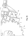
figures 2a and2b are perspective views of a detail of the parking brake infigure 1 , in a non operating configuration and in an operating configuration respectively; and -
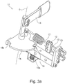
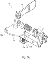
figures 3a and3b are perspective views of a detail of the parking brake infigure 1 , in two respective operating configurations. - With reference to the accompanying drawings, numeral 1 indicates a parking brake according to the present invention.
- Brake 1 comprises a
disc 2. Such adisc 2 is coaxially fixable to the wheel of a vehicle, as occurs for braking systems. Advantageously,disc 2 may also serve as a service brake. - In particular,
disc 2 has anedge 2a, on which there is formed at least aseat 3. In the preferred embodiment,disc 2 has a plurality of seats 3formed on the mentionededge 2a. Preferably, theseats 3 are angularly equally spaced with respect to the centre ofdisc 2. - In greater detail,
edge 2a ofdisc 2 has a profile with a plurality of ridges and valleys. Each valley defines arespective seat 3. In the preferred embodiment, the valleys are portions of a circumference. In alternative embodiments,edge 2a and/or pin 5 may have other profiles, e.g. sinusoidal. - Brake 1 comprises locking means 4 associated with
disc 2. Such locking means 4 serve the purpose of preventing the rotation ofdisc 2. - In detail, the locking means 4 comprise a pin 5 associated with
disc 2. Such a pin 5 is switchable between a locking configuration and an unlocking configuration. In the locking configuration, shown infigure 2b , pin 5 interferes withseat 3 so as to prevent the rotation ofdisc 2 and, accordingly, the rotation of the wheel of the vehicle connected thereto. As shown infigure 2a , in the unlocking configuration, pin 5 is removed fromseat 3, thus allowing the rotation ofdisc 2. In other words, pin 5 is in contact withdisc 2 in the locking configuration, while it is separated therefrom in the unlocking configuration. - In greater detail, pin 5 can be at least partially inserted inside
seat 3. In other words, pin 5 is received byseat 3, in particular in the locking configuration. In other words again, pin 5 may be accommodated insideseat 3. - Pin 5 has a rotation axis "A", and is configured to rotate with respect thereto. Thereby, pin 5 switches from the locking configuration to the unlocking configuration and vice versa by rotating on its rotation axis "A".
- In particular, pin 5 has a pair of
opposite ends outer surface 5c develops between theends first end 5a is movable to move away from/approach disc 2, while asecond end 5b is placed close to the rotation axis "A". In other words, the pin develops along a longitudinal axis "B", which passes through theends outer surface 5c of pin 5 is cylindrical. Advantageously, thereby there is an optimal interaction between pin 5 andedge 2a ofdisc 2, because pin 5 slides insideseat 3 with the minimum friction, thus switching from the unlocking configuration to the locking configuration. - It is also worth noting that the rotation axis "A" of pin 5 is arranged on a plane parallel to the layingplane of
disc 2. In an embodiment (not shown) of the invention, the rotation axis "A" of pin 5 may also be arranged transversal with respect to the laying plane ofdisc 2. Preferably, the rotation axis "A" of pin 5 is not perpendicular to the plane ofdisc 2. - Brake 1 further comprises a supporting element 6 of pin 5. In particular, the supporting element 6 is fixable to a chassis of a vehicle (not shown). By mere way of example, the supporting element 6 may be fixed to the fork of a motor vehicle.
- Pin 5 may rotate with respect to the supporting element 6. In particular, a
hinge 7 is arranged between pin 5 and the supporting element 6. The axis ofhinge 7 defines the rotation axis "A" of pin 5. - Brake 1 comprises actuating means 11 configured to be controlled by a user so as to allow such a user to move pin 5 from the locking configuration to the unlocking configuration and vice versa.
- In greater detail, the actuating means 11 comprise an
arm 10 fixed to pin 5. In particular,arm 10 is arranged along the longitudinal axis "B" of pin 5. In other words,arm 10 is coaxial with respect to pin 5. It is worth noting thatarm 10 is in a position opposite to pin 5 with respect to the rotation axis "A". - The actuating means 11 comprise a linkage12 which, in the preferred embodiment, may comprise one or
more cables 13. Linkage12, and in particular thecables 13, are connected to arm 10 at a predetermined distance from the rotation axis "A" of pin 5 so as to exert an actuating motion on pin 5 througharm 10. - A
lever 14 is connected to linkage12, as shown in particular infigures 3a and3b . In particular,lever 14 may rotate with respect to its rotation axis "C". The actuating means further comprise acam 15, fixed to lever 14 so as to rotate with respect to the rotation axis "C" oflever 14. In greater detail, the cam is arranged perpendicular with respect to the rotation axis "C" oflever 14. In particular, linkage12 is fixed tocam 15 at a predetermined distance with respect to the rotation axis "C" oflever 14, so that a rotation oflever 14 with respect to its rotation axis "C"moves linkage12. Such a linkage12 controls pin 5 as described above. - Finally, it is worth noting that the actuating means 11 in an alternative embodiment (not shown) may also be of the electromechanical type.
- Brake 1 further comprises linkage means 8 arranged between pin 5 and the supporting element 6. Such linkage means 8 are in particular configured to act at least along a direction perpendicular to the rotation axis "A" of pin 5. In other words, such linkage means 8 are configured to exert a countering action with respect to the action of the actuating means 11 described above. In even greater detail, the linkage means 8 are connected to pin 5 at a predetermined distance from the rotation axis "A", so as to exert a linkage motion on pin 5 which tends to bring it from the locking configuration to the unlocking configuration. Accordingly, it is necessary to exert a predetermined force to bring pin 5 into locking configuration. Advantageously, thereby an accidental or inhomogeneous actuation of brake 1 is prevented.
- In the preferred embodiment, such linkage means 8 are of elastic type. In alternative embodiments (not shown), the linkage means 8 may be of any type, e.g. electromechanical.
- In greater detail, the linkage means 8 comprise a
spring 9 fixed to pin 5. Such aspring 9 has a pair ofends first end 9a is connected to the supporting element 6, while asecond end 9b is connected to pin 5. - Brake 1 further comprises a
safety device 16, which is enabled on the actuating means 11, in particular oncam 15. In greater detail,cam 15 has at least aside 15a. Thesafety device 16 comprises afurther pin 17 configured to interfere with said at least aside 15a of cam 5 and, accordingly, prevent the rotation ofcam 15 and the actuation of pin 5. - Preferably, said cam has two
sides 15a adapted to interfere with saidfurther pin 17. In particular, thefurther pin 17 may switch from a locking configuration to an unlocking configuration and vice versa. In the unlocking configuration, shown infigure 3a , thefurther pin 17 is retracted, andcam 15 is free to rotate with respect to rotation axis "C" oflever 14, thus allowing the actuation of brake 1. In the locking configuration, shown infigure 3b , the pin interferes with one of thesides 15a ofcam 15, so as to prevent the rotation thereof, thus preventing the user from enabling or disabling brake 1, according to which of the twosides 15a is engaged by saidfurther pin 17. Advantageously, thefurther pin 17 may be actuated by a key (not shown), so as to perform the function of anti-theft device and/or safety device, thus allowing the key to be removed from the instrument panel only provided that the parking brake is properly engaged. - When the user wants to intervene on the actuating means 11, in particular on
lever 14, to release the parking brake 1, this will be possible only if the user has inserted and unlocked, when necessary, thefurther pin 17 by means of the ignition key, and the samefurther pin 17 will interfere with theother side 15a to ensure that, during running,cam 15 and therefore the actuating means 11 are locked in the unlocking position of pin 5. - The present invention achieves the objects proposed as discussed above, to which significant advantages are added.
- In particular, the disc is configured to operate as a disc of a braking system of a vehicle. Accordingly, a calliper (not part of the present invention) may act on the disc during the running of the vehicle to brake the wheel to which the disc is fixed. Furthermore, the seats formed on the edge of the disc allow using the same as a "phonic wheel", thus using a sensor located on the side of the disc capable of detecting the passing of the seats. It is possible to trace the rotation speed of the disc and, accordingly, the speed of the vehicle from the number of seats that pass at the sensor in the unit of time.
Claims (8)
- Parking brake (1) comprising a disc (2) coaxially fixable to the wheel of a vehicle and having an edge (2a); locking means (4) associated with said disc (2) for preventing the rotation of said disc (2); said disc (2) having at least a seat (3) formed on said edge (2a); said locking means (4) comprising a pin (5) associated with the disc (2) and switchable between a locking configuration in which said pin (5) interferes with said seat (3) to prevent the rotation of said disc (2), and an unlocking configuration in which said pin (5) is removed from said seat (3) to allow the rotation of said disc (2);
characterized in that said pin (5) has a rotation axis (A) arranged on a plane parallel to the plane of said disc (2), said pin (5) being configured for rotating with respect to said rotation axis (A) in order to reversibly switch from said locking configuration to said unlocking configuration. - Parking brake (1) according to claim 1, characterized in that said pin (5) can be at least partially inserted inside said seat (3).
- Parking brake (1) according to claim 1 or 2, characterized in that it comprises a supporting element (6) of said pin (5), said supporting element (6) being fixable to a chassis of a vehicle, said pin (5) being rotatable with respect to said supporting element (6) by means of a hinge (7) arranged between said pin (5) and said supporting element (6).
- Parking brake (1) according to any one of the preceding claims 1 to 3, characterized in that it comprises linkage means (8) arranged between said pin (5) and said supporting element (6).
- Parking brake (1) according to claim 4, characterized in that said linkage means (8) are configured for acting at least along a direction perpendicular to said rotation axis (A).
- Parking brake (1) according to any one of the preceding claims 1 to 5, characterized in that said disc (2) is a brake disc of a braking system of a vehicle.
- Parking brake (1) according to any one of the preceding claims 1 to 6, characterized in that said edge (2a) of said disc (2) has a profile having a plurality of ridges and valleys, each valley defining a respective seat (3) for said pin (5), said ridges and/or said valleys being preferably portions of a circumference.
- Parking brake (1) according to any one of the preceding claims 1 to 7, characterized in that said pin (5) has a cylindrical cross section.
Applications Claiming Priority (2)
| Application Number | Priority Date | Filing Date | Title |
|---|---|---|---|
| IT001559A ITMI20131559A1 (en) | 2013-09-23 | 2013-09-23 | PARKING BRAKE |
| PCT/IB2014/064757 WO2015040600A2 (en) | 2013-09-23 | 2014-09-23 | Parking brake |
Publications (2)
| Publication Number | Publication Date |
|---|---|
| EP3049291A2 EP3049291A2 (en) | 2016-08-03 |
| EP3049291B1 true EP3049291B1 (en) | 2020-10-28 |
Family
ID=49639988
Family Applications (1)
| Application Number | Title | Priority Date | Filing Date |
|---|---|---|---|
| EP14796259.1A Active EP3049291B1 (en) | 2013-09-23 | 2014-09-23 | Parking brake |
Country Status (7)
| Country | Link |
|---|---|
| US (1) | US9950696B2 (en) |
| EP (1) | EP3049291B1 (en) |
| JP (1) | JP6505113B2 (en) |
| CN (1) | CN105980223B (en) |
| ES (1) | ES2833152T3 (en) |
| IT (1) | ITMI20131559A1 (en) |
| WO (1) | WO2015040600A2 (en) |
Families Citing this family (3)
| Publication number | Priority date | Publication date | Assignee | Title |
|---|---|---|---|---|
| DE102019109465A1 (en) * | 2019-04-10 | 2020-10-15 | Bayerische Motoren Werke Aktiengesellschaft | Brake system of a vehicle |
| DE102019110571A1 (en) | 2019-04-24 | 2020-10-29 | Dr. Ing. H.C. F. Porsche Aktiengesellschaft | Safety device for securing a standstill of a vehicle |
| IT202000004459A1 (en) * | 2020-03-03 | 2021-09-03 | Piaggio & C Spa | A PARKING BRAKE FOR A MOTORCYCLE AND MOTORCYCLE INCLUDING THE PARKING BRAKE |
Family Cites Families (21)
| Publication number | Priority date | Publication date | Assignee | Title |
|---|---|---|---|---|
| US1523304A (en) * | 1923-09-24 | 1925-01-13 | Walter J Spiro | Disk brake |
| US2974752A (en) * | 1957-09-03 | 1961-03-14 | Gen Motors Corp | Positive parking brake |
| US3952838A (en) * | 1975-03-17 | 1976-04-27 | J. I. Case Company | Transmission park-lock mechanism |
| US4907681A (en) * | 1988-04-29 | 1990-03-13 | Chrysler Motors Corporation | Park locking mechanism for an automatic transmission |
| US4934490A (en) * | 1989-03-14 | 1990-06-19 | Chang Deng J | Anti-roll device for vehicles |
| US5065848A (en) * | 1989-11-27 | 1991-11-19 | Barrett David M | Brake-disc-rotor attacher impeller (intersecting/locker) |
| JP2535802Y2 (en) * | 1991-10-22 | 1997-05-14 | 株式会社 神崎高級工機製作所 | Parking lock device |
| JPH06255459A (en) * | 1992-02-10 | 1994-09-13 | Soretsukusu Kk | Vehicular auxiliary brake for trailer and the like |
| SE508289C2 (en) | 1997-01-28 | 1998-09-21 | Ericsson Telefon Ab L M | Method and apparatus for monitoring and controlling oscillator signal |
| US5992576A (en) * | 1997-06-16 | 1999-11-30 | Clark Equipment Company | Parking lock with secondary brake |
| DE19816801C2 (en) * | 1998-04-16 | 2001-03-22 | Daimler Chrysler Ag | Blocking device for a vehicle |
| US6250433B1 (en) * | 1999-05-24 | 2001-06-26 | Case Corporation | Positive-locking vehicular parking brake |
| JP2001328514A (en) * | 2000-05-18 | 2001-11-27 | Suzuki Motor Corp | Parking lock device for saddle type vehicles |
| JP4584425B2 (en) * | 2000-08-10 | 2010-11-24 | 本田技研工業株式会社 | Parking lock device for tricycle |
| DE10309274A1 (en) * | 2002-04-11 | 2003-10-30 | Ina Schaeffler Kg | Ratchet mechanism for a freewheel comprises a disk-type star wheel, and a pawl having two detent pins engaging in two adjacent catch recesses |
| ITVR20030004U1 (en) * | 2003-02-07 | 2004-08-08 | Inglesina Baby Spa | LOCKING / UNLOCKING DEVICE |
| JP4840598B2 (en) * | 2007-04-27 | 2011-12-21 | 日立オートモティブシステムズ株式会社 | Electric disc brake |
| DE202008001760U1 (en) * | 2008-02-01 | 2008-04-17 | Getrag Getriebe- Und Zahnradfabrik Hermann Hagenmeyer Gmbh & Cie Kg | Parking lock arrangement |
| CN201165227Y (en) * | 2008-02-18 | 2008-12-17 | 隆鑫工业有限公司 | Parking brake locking apparatus of motor vehicle |
| ITBO20080677A1 (en) * | 2008-11-11 | 2010-05-12 | Cnh Italia Spa | EQUIPMENT FOR THE BRAKING OF A VEHICLE, IN PARTICULAR, OF AN AGRICULTURAL TRACTOR |
| CN102774240B (en) * | 2012-08-09 | 2014-01-29 | 南京创捷和信汽车零部件有限公司 | rear drive axle assembly |
-
2013
- 2013-09-23 IT IT001559A patent/ITMI20131559A1/en unknown
-
2014
- 2014-09-23 ES ES14796259T patent/ES2833152T3/en active Active
- 2014-09-23 WO PCT/IB2014/064757 patent/WO2015040600A2/en not_active Ceased
- 2014-09-23 US US15/023,720 patent/US9950696B2/en active Active
- 2014-09-23 CN CN201480052158.1A patent/CN105980223B/en active Active
- 2014-09-23 JP JP2016543487A patent/JP6505113B2/en active Active
- 2014-09-23 EP EP14796259.1A patent/EP3049291B1/en active Active
Non-Patent Citations (1)
| Title |
|---|
| None * |
Also Published As
| Publication number | Publication date |
|---|---|
| JP2016530471A (en) | 2016-09-29 |
| EP3049291A2 (en) | 2016-08-03 |
| WO2015040600A3 (en) | 2015-11-19 |
| ITMI20131559A1 (en) | 2015-03-24 |
| ES2833152T3 (en) | 2021-06-14 |
| WO2015040600A2 (en) | 2015-03-26 |
| US9950696B2 (en) | 2018-04-24 |
| JP6505113B2 (en) | 2019-04-24 |
| CN105980223A (en) | 2016-09-28 |
| CN105980223B (en) | 2019-06-14 |
| US20160229381A1 (en) | 2016-08-11 |
Similar Documents
| Publication | Publication Date | Title |
|---|---|---|
| EP3164277B1 (en) | Electronic braking device of the tilting system of a vehicle with three or more tilting wheels | |
| CN113646554B (en) | Brake system for vehicle | |
| EP1561612B1 (en) | Anti-rolling device for vehicles | |
| US9950696B2 (en) | Parking brake | |
| US10737125B2 (en) | Fall arrest device | |
| JP6255164B2 (en) | Bar end electric actuator for bicycle gearshift | |
| JP6255775B2 (en) | Brake control device | |
| US20120279348A1 (en) | Motorcycle Lever Protection Guard | |
| JP6576838B2 (en) | Shift device | |
| JP2011512296A (en) | Tractor brake and steer-by-braking pedal device | |
| EP3032125B1 (en) | Disc brake and components thereof | |
| KR101653406B1 (en) | A braking device provided with baby carriage | |
| EP2886400B1 (en) | Antitheft steering column lock | |
| EP3835182B1 (en) | Lean vehicle | |
| EP3437965B1 (en) | Bicycle brake lock device and bicycle brake assembly comprising same | |
| KR101689728B1 (en) | Brake control method for two-wheeler | |
| JP2021066272A (en) | Electric parking brake device | |
| SE532650C2 (en) | Parking brake device for vehicles | |
| GB1587778A (en) | Disc parking brakes | |
| CN107244376A (en) | Drum brake for vehicle | |
| CN111845662A (en) | Fixtures for securing the vehicle at a standstill | |
| KR100402770B1 (en) | Safety Appatus for Automobile Steering System | |
| RU2047513C1 (en) | Antitheft device for vehicles | |
| GB2359350A (en) | Cycle brakes | |
| KR200152332Y1 (en) | Anti-locking brake system |
Legal Events
| Date | Code | Title | Description |
|---|---|---|---|
| PUAI | Public reference made under article 153(3) epc to a published international application that has entered the european phase |
Free format text: ORIGINAL CODE: 0009012 |
|
| 17P | Request for examination filed |
Effective date: 20160422 |
|
| AK | Designated contracting states |
Kind code of ref document: A2 Designated state(s): AL AT BE BG CH CY CZ DE DK EE ES FI FR GB GR HR HU IE IS IT LI LT LU LV MC MK MT NL NO PL PT RO RS SE SI SK SM TR |
|
| AX | Request for extension of the european patent |
Extension state: BA ME |
|
| RIN1 | Information on inventor provided before grant (corrected) |
Inventor name: MARABESE, RICCARDO Inventor name: MORONI, MARCO |
|
| DAX | Request for extension of the european patent (deleted) | ||
| RAP1 | Party data changed (applicant data changed or rights of an application transferred) |
Owner name: QUADRO VEHICLES S.A. |
|
| GRAP | Despatch of communication of intention to grant a patent |
Free format text: ORIGINAL CODE: EPIDOSNIGR1 |
|
| STAA | Information on the status of an ep patent application or granted ep patent |
Free format text: STATUS: GRANT OF PATENT IS INTENDED |
|
| INTG | Intention to grant announced |
Effective date: 20200515 |
|
| GRAS | Grant fee paid |
Free format text: ORIGINAL CODE: EPIDOSNIGR3 |
|
| GRAA | (expected) grant |
Free format text: ORIGINAL CODE: 0009210 |
|
| STAA | Information on the status of an ep patent application or granted ep patent |
Free format text: STATUS: THE PATENT HAS BEEN GRANTED |
|
| AK | Designated contracting states |
Kind code of ref document: B1 Designated state(s): AL AT BE BG CH CY CZ DE DK EE ES FI FR GB GR HR HU IE IS IT LI LT LU LV MC MK MT NL NO PL PT RO RS SE SI SK SM TR |
|
| RAP1 | Party data changed (applicant data changed or rights of an application transferred) |
Owner name: QOODER SA |
|
| REG | Reference to a national code |
Ref country code: GB Ref legal event code: FG4D |
|
| RIN1 | Information on inventor provided before grant (corrected) |
Inventor name: MARABESE, RICCARDO Inventor name: MORONI, MARCO |
|
| REG | Reference to a national code |
Ref country code: CH Ref legal event code: EP |
|
| REG | Reference to a national code |
Ref country code: AT Ref legal event code: REF Ref document number: 1327911 Country of ref document: AT Kind code of ref document: T Effective date: 20201115 |
|
| REG | Reference to a national code |
Ref country code: DE Ref legal event code: R096 Ref document number: 602014071753 Country of ref document: DE |
|
| REG | Reference to a national code |
Ref country code: IE Ref legal event code: FG4D |
|
| REG | Reference to a national code |
Ref country code: AT Ref legal event code: MK05 Ref document number: 1327911 Country of ref document: AT Kind code of ref document: T Effective date: 20201028 |
|
| REG | Reference to a national code |
Ref country code: NL Ref legal event code: MP Effective date: 20201028 |
|
| PG25 | Lapsed in a contracting state [announced via postgrant information from national office to epo] |
Ref country code: NL Free format text: LAPSE BECAUSE OF FAILURE TO SUBMIT A TRANSLATION OF THE DESCRIPTION OR TO PAY THE FEE WITHIN THE PRESCRIBED TIME-LIMIT Effective date: 20201028 Ref country code: PT Free format text: LAPSE BECAUSE OF FAILURE TO SUBMIT A TRANSLATION OF THE DESCRIPTION OR TO PAY THE FEE WITHIN THE PRESCRIBED TIME-LIMIT Effective date: 20210301 Ref country code: NO Free format text: LAPSE BECAUSE OF FAILURE TO SUBMIT A TRANSLATION OF THE DESCRIPTION OR TO PAY THE FEE WITHIN THE PRESCRIBED TIME-LIMIT Effective date: 20210128 Ref country code: RS Free format text: LAPSE BECAUSE OF FAILURE TO SUBMIT A TRANSLATION OF THE DESCRIPTION OR TO PAY THE FEE WITHIN THE PRESCRIBED TIME-LIMIT Effective date: 20201028 Ref country code: FI Free format text: LAPSE BECAUSE OF FAILURE TO SUBMIT A TRANSLATION OF THE DESCRIPTION OR TO PAY THE FEE WITHIN THE PRESCRIBED TIME-LIMIT Effective date: 20201028 Ref country code: GR Free format text: LAPSE BECAUSE OF FAILURE TO SUBMIT A TRANSLATION OF THE DESCRIPTION OR TO PAY THE FEE WITHIN THE PRESCRIBED TIME-LIMIT Effective date: 20210129 |
|
| REG | Reference to a national code |
Ref country code: LT Ref legal event code: MG4D |
|
| PG25 | Lapsed in a contracting state [announced via postgrant information from national office to epo] |
Ref country code: AT Free format text: LAPSE BECAUSE OF FAILURE TO SUBMIT A TRANSLATION OF THE DESCRIPTION OR TO PAY THE FEE WITHIN THE PRESCRIBED TIME-LIMIT Effective date: 20201028 Ref country code: BG Free format text: LAPSE BECAUSE OF FAILURE TO SUBMIT A TRANSLATION OF THE DESCRIPTION OR TO PAY THE FEE WITHIN THE PRESCRIBED TIME-LIMIT Effective date: 20210128 Ref country code: PL Free format text: LAPSE BECAUSE OF FAILURE TO SUBMIT A TRANSLATION OF THE DESCRIPTION OR TO PAY THE FEE WITHIN THE PRESCRIBED TIME-LIMIT Effective date: 20201028 Ref country code: SE Free format text: LAPSE BECAUSE OF FAILURE TO SUBMIT A TRANSLATION OF THE DESCRIPTION OR TO PAY THE FEE WITHIN THE PRESCRIBED TIME-LIMIT Effective date: 20201028 Ref country code: IS Free format text: LAPSE BECAUSE OF FAILURE TO SUBMIT A TRANSLATION OF THE DESCRIPTION OR TO PAY THE FEE WITHIN THE PRESCRIBED TIME-LIMIT Effective date: 20210228 Ref country code: LV Free format text: LAPSE BECAUSE OF FAILURE TO SUBMIT A TRANSLATION OF THE DESCRIPTION OR TO PAY THE FEE WITHIN THE PRESCRIBED TIME-LIMIT Effective date: 20201028 |
|
| REG | Reference to a national code |
Ref country code: ES Ref legal event code: FG2A Ref document number: 2833152 Country of ref document: ES Kind code of ref document: T3 Effective date: 20210614 |
|
| PG25 | Lapsed in a contracting state [announced via postgrant information from national office to epo] |
Ref country code: HR Free format text: LAPSE BECAUSE OF FAILURE TO SUBMIT A TRANSLATION OF THE DESCRIPTION OR TO PAY THE FEE WITHIN THE PRESCRIBED TIME-LIMIT Effective date: 20201028 |
|
| REG | Reference to a national code |
Ref country code: DE Ref legal event code: R097 Ref document number: 602014071753 Country of ref document: DE |
|
| PG25 | Lapsed in a contracting state [announced via postgrant information from national office to epo] |
Ref country code: SM Free format text: LAPSE BECAUSE OF FAILURE TO SUBMIT A TRANSLATION OF THE DESCRIPTION OR TO PAY THE FEE WITHIN THE PRESCRIBED TIME-LIMIT Effective date: 20201028 Ref country code: CZ Free format text: LAPSE BECAUSE OF FAILURE TO SUBMIT A TRANSLATION OF THE DESCRIPTION OR TO PAY THE FEE WITHIN THE PRESCRIBED TIME-LIMIT Effective date: 20201028 Ref country code: EE Free format text: LAPSE BECAUSE OF FAILURE TO SUBMIT A TRANSLATION OF THE DESCRIPTION OR TO PAY THE FEE WITHIN THE PRESCRIBED TIME-LIMIT Effective date: 20201028 Ref country code: SK Free format text: LAPSE BECAUSE OF FAILURE TO SUBMIT A TRANSLATION OF THE DESCRIPTION OR TO PAY THE FEE WITHIN THE PRESCRIBED TIME-LIMIT Effective date: 20201028 Ref country code: RO Free format text: LAPSE BECAUSE OF FAILURE TO SUBMIT A TRANSLATION OF THE DESCRIPTION OR TO PAY THE FEE WITHIN THE PRESCRIBED TIME-LIMIT Effective date: 20201028 Ref country code: LT Free format text: LAPSE BECAUSE OF FAILURE TO SUBMIT A TRANSLATION OF THE DESCRIPTION OR TO PAY THE FEE WITHIN THE PRESCRIBED TIME-LIMIT Effective date: 20201028 |
|
| PG25 | Lapsed in a contracting state [announced via postgrant information from national office to epo] |
Ref country code: DK Free format text: LAPSE BECAUSE OF FAILURE TO SUBMIT A TRANSLATION OF THE DESCRIPTION OR TO PAY THE FEE WITHIN THE PRESCRIBED TIME-LIMIT Effective date: 20201028 |
|
| PLBE | No opposition filed within time limit |
Free format text: ORIGINAL CODE: 0009261 |
|
| STAA | Information on the status of an ep patent application or granted ep patent |
Free format text: STATUS: NO OPPOSITION FILED WITHIN TIME LIMIT |
|
| 26N | No opposition filed |
Effective date: 20210729 |
|
| PG25 | Lapsed in a contracting state [announced via postgrant information from national office to epo] |
Ref country code: AL Free format text: LAPSE BECAUSE OF FAILURE TO SUBMIT A TRANSLATION OF THE DESCRIPTION OR TO PAY THE FEE WITHIN THE PRESCRIBED TIME-LIMIT Effective date: 20201028 |
|
| PG25 | Lapsed in a contracting state [announced via postgrant information from national office to epo] |
Ref country code: SI Free format text: LAPSE BECAUSE OF FAILURE TO SUBMIT A TRANSLATION OF THE DESCRIPTION OR TO PAY THE FEE WITHIN THE PRESCRIBED TIME-LIMIT Effective date: 20201028 |
|
| REG | Reference to a national code |
Ref country code: CH Ref legal event code: PL |
|
| REG | Reference to a national code |
Ref country code: BE Ref legal event code: MM Effective date: 20210930 |
|
| PG25 | Lapsed in a contracting state [announced via postgrant information from national office to epo] |
Ref country code: IS Free format text: LAPSE BECAUSE OF FAILURE TO SUBMIT A TRANSLATION OF THE DESCRIPTION OR TO PAY THE FEE WITHIN THE PRESCRIBED TIME-LIMIT Effective date: 20210228 Ref country code: MC Free format text: LAPSE BECAUSE OF FAILURE TO SUBMIT A TRANSLATION OF THE DESCRIPTION OR TO PAY THE FEE WITHIN THE PRESCRIBED TIME-LIMIT Effective date: 20201028 |
|
| PG25 | Lapsed in a contracting state [announced via postgrant information from national office to epo] |
Ref country code: LU Free format text: LAPSE BECAUSE OF NON-PAYMENT OF DUE FEES Effective date: 20210923 Ref country code: IE Free format text: LAPSE BECAUSE OF NON-PAYMENT OF DUE FEES Effective date: 20210923 Ref country code: BE Free format text: LAPSE BECAUSE OF NON-PAYMENT OF DUE FEES Effective date: 20210930 |
|
| PG25 | Lapsed in a contracting state [announced via postgrant information from national office to epo] |
Ref country code: LI Free format text: LAPSE BECAUSE OF NON-PAYMENT OF DUE FEES Effective date: 20210930 Ref country code: CH Free format text: LAPSE BECAUSE OF NON-PAYMENT OF DUE FEES Effective date: 20210930 |
|
| PG25 | Lapsed in a contracting state [announced via postgrant information from national office to epo] |
Ref country code: HU Free format text: LAPSE BECAUSE OF FAILURE TO SUBMIT A TRANSLATION OF THE DESCRIPTION OR TO PAY THE FEE WITHIN THE PRESCRIBED TIME-LIMIT; INVALID AB INITIO Effective date: 20140923 |
|
| PG25 | Lapsed in a contracting state [announced via postgrant information from national office to epo] |
Ref country code: CY Free format text: LAPSE BECAUSE OF FAILURE TO SUBMIT A TRANSLATION OF THE DESCRIPTION OR TO PAY THE FEE WITHIN THE PRESCRIBED TIME-LIMIT Effective date: 20201028 |
|
| PG25 | Lapsed in a contracting state [announced via postgrant information from national office to epo] |
Ref country code: MK Free format text: LAPSE BECAUSE OF FAILURE TO SUBMIT A TRANSLATION OF THE DESCRIPTION OR TO PAY THE FEE WITHIN THE PRESCRIBED TIME-LIMIT Effective date: 20201028 |
|
| PG25 | Lapsed in a contracting state [announced via postgrant information from national office to epo] |
Ref country code: TR Free format text: LAPSE BECAUSE OF FAILURE TO SUBMIT A TRANSLATION OF THE DESCRIPTION OR TO PAY THE FEE WITHIN THE PRESCRIBED TIME-LIMIT Effective date: 20201028 |
|
| PG25 | Lapsed in a contracting state [announced via postgrant information from national office to epo] |
Ref country code: MT Free format text: LAPSE BECAUSE OF FAILURE TO SUBMIT A TRANSLATION OF THE DESCRIPTION OR TO PAY THE FEE WITHIN THE PRESCRIBED TIME-LIMIT Effective date: 20201028 |
|
| PGFP | Annual fee paid to national office [announced via postgrant information from national office to epo] |
Ref country code: DE Payment date: 20250923 Year of fee payment: 12 |
|
| PGFP | Annual fee paid to national office [announced via postgrant information from national office to epo] |
Ref country code: IT Payment date: 20250725 Year of fee payment: 12 |
|
| PGFP | Annual fee paid to national office [announced via postgrant information from national office to epo] |
Ref country code: GB Payment date: 20250919 Year of fee payment: 12 |
|
| PGFP | Annual fee paid to national office [announced via postgrant information from national office to epo] |
Ref country code: FR Payment date: 20250829 Year of fee payment: 12 |
|
| PGFP | Annual fee paid to national office [announced via postgrant information from national office to epo] |
Ref country code: ES Payment date: 20251001 Year of fee payment: 12 |
|
| REG | Reference to a national code |
Ref country code: DE Ref legal event code: R081 Ref document number: 602014071753 Country of ref document: DE Owner name: QOODER S.A., CH Free format text: FORMER OWNER: QOODER SA, VACALLO, CH |