EP3048746B1 - Procédé et dispositif pour une estimation de dispersion chromatique dans une communication cohérente optique - Google Patents
Procédé et dispositif pour une estimation de dispersion chromatique dans une communication cohérente optique Download PDFInfo
- Publication number
- EP3048746B1 EP3048746B1 EP14797641.9A EP14797641A EP3048746B1 EP 3048746 B1 EP3048746 B1 EP 3048746B1 EP 14797641 A EP14797641 A EP 14797641A EP 3048746 B1 EP3048746 B1 EP 3048746B1
- Authority
- EP
- European Patent Office
- Prior art keywords
- dispersion
- fourier transform
- frequency domain
- polarization directions
- domain data
- Prior art date
- Legal status (The legal status is an assumption and is not a legal conclusion. Google has not performed a legal analysis and makes no representation as to the accuracy of the status listed.)
- Active
Links
Images


Classifications
-
- H—ELECTRICITY
- H04—ELECTRIC COMMUNICATION TECHNIQUE
- H04B—TRANSMISSION
- H04B10/00—Transmission systems employing electromagnetic waves other than radio-waves, e.g. infrared, visible or ultraviolet light, or employing corpuscular radiation, e.g. quantum communication
- H04B10/07—Arrangements for monitoring or testing transmission systems; Arrangements for fault measurement of transmission systems
- H04B10/075—Arrangements for monitoring or testing transmission systems; Arrangements for fault measurement of transmission systems using an in-service signal
- H04B10/079—Arrangements for monitoring or testing transmission systems; Arrangements for fault measurement of transmission systems using an in-service signal using measurements of the data signal
- H04B10/0795—Performance monitoring; Measurement of transmission parameters
- H04B10/07951—Monitoring or measuring chromatic dispersion or PMD
-
- H—ELECTRICITY
- H04—ELECTRIC COMMUNICATION TECHNIQUE
- H04B—TRANSMISSION
- H04B10/00—Transmission systems employing electromagnetic waves other than radio-waves, e.g. infrared, visible or ultraviolet light, or employing corpuscular radiation, e.g. quantum communication
- H04B10/60—Receivers
- H04B10/61—Coherent receivers
- H04B10/613—Coherent receivers including phase diversity, e.g., having in-phase and quadrature branches, as in QPSK coherent receivers
-
- H—ELECTRICITY
- H04—ELECTRIC COMMUNICATION TECHNIQUE
- H04B—TRANSMISSION
- H04B10/00—Transmission systems employing electromagnetic waves other than radio-waves, e.g. infrared, visible or ultraviolet light, or employing corpuscular radiation, e.g. quantum communication
- H04B10/60—Receivers
- H04B10/61—Coherent receivers
- H04B10/612—Coherent receivers for optical signals modulated with a format different from binary or higher-order PSK [X-PSK], e.g. QAM, DPSK, FSK, MSK, ASK
-
- H—ELECTRICITY
- H04—ELECTRIC COMMUNICATION TECHNIQUE
- H04B—TRANSMISSION
- H04B10/00—Transmission systems employing electromagnetic waves other than radio-waves, e.g. infrared, visible or ultraviolet light, or employing corpuscular radiation, e.g. quantum communication
- H04B10/60—Receivers
- H04B10/61—Coherent receivers
- H04B10/616—Details of the electronic signal processing in coherent optical receivers
- H04B10/6161—Compensation of chromatic dispersion
-
- H—ELECTRICITY
- H04—ELECTRIC COMMUNICATION TECHNIQUE
- H04B—TRANSMISSION
- H04B10/00—Transmission systems employing electromagnetic waves other than radio-waves, e.g. infrared, visible or ultraviolet light, or employing corpuscular radiation, e.g. quantum communication
- H04B10/60—Receivers
- H04B10/61—Coherent receivers
- H04B10/616—Details of the electronic signal processing in coherent optical receivers
- H04B10/6165—Estimation of the phase of the received optical signal, phase error estimation or phase error correction
-
- H—ELECTRICITY
- H04—ELECTRIC COMMUNICATION TECHNIQUE
- H04B—TRANSMISSION
- H04B10/00—Transmission systems employing electromagnetic waves other than radio-waves, e.g. infrared, visible or ultraviolet light, or employing corpuscular radiation, e.g. quantum communication
- H04B10/60—Receivers
- H04B10/61—Coherent receivers
- H04B10/616—Details of the electronic signal processing in coherent optical receivers
- H04B10/6166—Polarisation demultiplexing, tracking or alignment of orthogonal polarisation components
-
- H—ELECTRICITY
- H04—ELECTRIC COMMUNICATION TECHNIQUE
- H04B—TRANSMISSION
- H04B10/00—Transmission systems employing electromagnetic waves other than radio-waves, e.g. infrared, visible or ultraviolet light, or employing corpuscular radiation, e.g. quantum communication
- H04B10/60—Receivers
- H04B10/61—Coherent receivers
- H04B10/616—Details of the electronic signal processing in coherent optical receivers
- H04B10/6163—Compensation of non-linear effects in the fiber optic link, e.g. self-phase modulation [SPM], cross-phase modulation [XPM], four wave mixing [FWM]
Definitions
- the present invention relates to the field of chromatic dispersion estimation technologies in the optical coherent communication, and more particularly, to a chromatic dispersion estimation method and device in the optical coherent communication.
- the digital coherent reception technology Compared with the incoherent technology, the digital coherent reception technology has the following advantages: it has approximately 3dB optical signal to noise ratio (OSNR) gain; it can easily adopt the electronic equalization technique to cope with channel variations and reduce costs; it can use more efficient modulation techniques and polarization multiplexing to increase the transmission capacity.
- OSNR optical signal to noise ratio
- the digital coherent technology is considered as a key technology in the high-speed optical communication system.
- the optical coherent receiver In the optical coherent receiver, the signal light and the local oscillation light are mixed, amplitude information and phase information of the signal light are moved to the baseband signal, thus the optical coherent detection retains all the information of the light field and can take the advantages of the digital signal processing technology in features and performance.
- Using the electric equalization technology can almost completely compensate for linear distortions of the optical signal, such as compensating the chromatic dispersion (CD), the polarization mode dispersion (PMD), and the like.
- FIG. 1 (a) is a block diagram of a typical digital coherent receiver.
- the received optical signal is split into two mutually orthogonal polarization signals by a polarization beam splitter (PBS).
- the polarized signal output by the PBS is mixed with a local oscillation optical signal through a 90° optical mixer.
- the mixed optical signal is converted to a baseband electrical signal through a balancing photoelectrical detector.
- the photoelectrically-converted electrical signal has two signals for each polarization state, but the four signals do not correspond to the original four signals, this is because, after passing through the transmission channel, there is crosstalk between the two polarization states, and the polarization states rotate, the two polarization states at the receiving ends, the two orthogonal signals of each polarization state and the transmitted signals do not have a correspondence.
- the photoelectrically-converted electrical signal is converted into a digital signal by the ADC.
- the general digital signal processing technology can be used to process the ADC converted digital signal.
- the digital signal processing part comprises the IQ Skew compensation, the IQ imbalance compensation, chromatic dispersion (CD) compensation, dispersion estimation, clock recovery, polarization demultiplexing, carrier recovery, judgment detection.
- the IQ Skew adjusts delays of the 4 signals, and solves the inconsistencies in the delays of the 4 signals at the photoelectric conversion front end.
- the chromatic dispersion (CD) compensation unit often uses the sampling frequency domain fast convolution technique to compensate the chromatic dispersion of the optical link.
- the clock recovery adjusts the sampling phase, and provides data with a stable sampling phase for the polarization demultiplexing module thereafter.
- the polarization demultiplexing compensates the residual dispersion and polarization mode dispersion (PMD).
- the carrier recovery compensates for inconsistencies in frequencies of the local oscillation light at the receiving end and the carrier light at the sending end.
- the value of the chromatic dispersion (CD) is generally large
- the equalization of the chromatic dispersion and the polarization mode dispersion (PMD) is generally completed in two parts, first, static dispersion is compensated, wherein the equalizer usually cannot use a standard adaptive algorithm to update coefficients, such as compensating 40000ps/nm chromatic dispersion, the number of filter taps should reach big hundreds or even thousands, and typically the fast Fourier transform technology is used for frequency domain fast convolution.
- the dispersion estimation module provides the dispersion compensation module with dispersion value to be compensated.
- the compensation of the residual chromatic dispersion and polarization mode dispersion is achieved by a FIR butterfly equalizer, wherein the FIR butterfly filter uses an adaptive algorithm to update the coefficients to track and compensate the polarization mode dispersion that dynamically changes over time.
- the FIR butterfly equalizer is also known as polarization demultiplexing.
- the FIR butterfly adaptive equalizer has the functions of equalizing, matching and filtering, and sampling position adjusting. When the sampling position change range is too large, or the sampling frequency offset exists, the sampling phase change range exceeds the adjustment range of the FIR butterfly adaptive equalizer, it will cause the FIR butterfly adaptive equalizer to not work properly. It needs to place a clock recovery module before the FIR butterfly equalizer.
- the clock recovery estimates the sampling time error of an input symbol, and performs interpolation adjustment on the sampling time of the symbols, or adjusts the ADC sampling frequency via the VCO, to guarantee to provide a stable symbol sampling phase.
- the clock recovery phase detector needs to tolerate a certain signal distortion, while the conventional clock recovery usually can only tolerate small dispersion. In order to not increase the complexity of the clock recovery module, while currently there is a lack of clock recovery method that tolerances large residual dispersion value, it requires an accurate dispersion compensation.
- a dispersion interval with a certain step size is used to change the dispersion compensation amount of a dispersion compensation filter, until the system converges.
- the search process is slow and the accuracy is low.
- the optical fiber link is affected by the environmental temperature change, and the link dispersion value also changes slowly.
- CN103004110 shows an example of a previously known method for dispersion estimation.
- the embodiment of the present invention is to provide a dispersion estimation method and device in coherent optical communication to improve the dispersion measurement accuracy and efficiency.
- the step of performing a fast Fourier transform on IQ-imbalance compensated data to obtain frequency domain data in two polarization directions comprises:
- the step of respectively performing the fast inverse Fourier transform on the values of the two autocorrelation sequences to obtain two inverse Fourier transform results comprises:
- 2 , n - N ifft , ..., N ifft - 1, where N ifft is the number of Fourier transform points.
- the method further comprises: using an interpolation equation to correct the index n 0 .
- c is a speed of light in vacuum
- ⁇ is a wavelength of an optical carrier in vacuum
- f baud is a baud rate
- a dispersion estimation device in optical coherent communication comprising a dispersion compensation unit and a dispersion estimation unit, wherein:
- 2 , n ⁇ N ifft , ... , N ifft ⁇ 1.
- the dispersion estimation unit further comprises a correction module, wherein: the correction module is configured to: use an interpolation equation to correct the index n 0 .
- the dispersion compensation unit is configured to perform a fast Fourier transform on IQ-imbalance compensated data to obtain frequency domain data in two polarization directions in the following manner: using a frequency domain convolution transform on the IQ-imbalance compensated data to obtain the frequency domain data in the two polarization directions.
- the dispersion estimation unit further comprises: a Fourier transform module, which uses the fast Fourier transform on the IQ-imbalance compensated data to obtain frequency domain data in two polarization directions respectively.
- the abovementioned technical solution can directly calculate the dispersion without searching, thus, when the system starts, the value of the link dispersion can be quickly estimated.
- it may also continue to estimate the link dispersion value, track its change, and ensure the dispersion compensation module to precisely compensate the dispersion. It can achieve precise dispersion compensation, and can reduce the complexity of the clock recovery module thereafter, and the like.
- the abovementioned technical solution can very accurately estimate the dispersion value, and the estimation speed is fast.
- the embodiment of the present invention provides a dispersion estimation method in optical coherent communication, and as shown in FIG. 2 , it comprises the following steps: in step 200, it is to perform a fast Fourier transform on IQ-imbalance compensated data to obtain frequency domain data in two polarization directions;
- the dispersion compensation module uses the frequency domain convolution technology, and can provide frequency domain data for the CD estimation module.
- the CD estimation module separately performs FFT on the IQ-imbalance compensated time domain signal to obtain frequency domain data.
- kis the frequency index
- N fft is the number of Fourier transform points
- T s is the sampling interval of the digital signal in the time domain.
- step 201 it is to respectively calculate autocorrelation sequences of the frequency domain signals in the two polarization direction to obtain values of the autocorrelation sequences corresponding to the frequency domain signals in the two polarization directions; wherein, the interval for calculating the autocorrelation sequences is a baud rate.
- step 202 it is to respectively perform the fast inverse Fourier transform on the values of the two autocorrelation sequences in step 201 to obtain two inverse Fourier transform results.
- N ifft is the number of Fourier transform points.
- step 203 it is to respectively calculate modulus squares of the two fast inverse Fourier transform results in step 202 to obtain two modulus square results, and add the two modulus square results to obtain the sum of the modulus square results P [n].
- P n
- 2 , n ⁇ 1 N ifft , ... , N ifft ⁇ 1 in step 204, it is to perform the abovementioned steps 201-203 on multiple groups of IQ-imbalance compensated data to obtain sums of the multiple modulus square results, and average all the sums of the modulus square results to obtain a dispersion objective function P ⁇ [n].
- FIG. 3 shows the obtained P ⁇ [n] curve.
- the simulation condition is, the polarization multiplexing DQPSK coherent optical communication coefficients, the system bit rate is 112Gbit/s, the baud rate is 28Gbaud, the ADC sampling rate of the optical digital coherent receiver is twice of the standard rate.
- the number of Fourier transform points in step 200 is 4096, the number of inverse Fourier transform points in step 203 is also 4096.
- the chromatic dispersion value of the data sources used in the offline simulation is 48000ps/nm.
- step 205 it is to calculate the index n 0 of the maximum value of the dispersion objective function P ⁇ [n].
- n 0 ′ n 0 + P ⁇ n 0 ⁇ 1 ⁇ P ⁇ n 0 + 1 2 P ⁇ n 0 ⁇ 1 ⁇ 2 P ⁇ n 0 ⁇ P ⁇ n 0 + 1 ;
- FIG. 3 shows the P ⁇ [n] curve obtained when the chromatic dispersion value of the data source used in the offline simulation is 48000ps/nm, the integer index is calculated as 605, and the interpolated corrected accurate index is 605.0695.
- step 206 it is to estimate the optical fiber link dispersion value based on the index of the maximum value of the dispersion objective function P ⁇ [n].
- CD n 0 ′ ⁇ f ⁇ N ifft ⁇ c ⁇ 2 f baud
- c the speed of light in vacuum
- ⁇ the wavelength of the optical carrier in vacuum
- f baud the baud rate
- the abscissa in FIG. 3 represents the dispersion, as shown in FIG. 4 .
- the estimated dispersion value range is -162ns/nm to 162ns/nm.
- FIG. 5 is obtained by enlarging the local part of FIG. 4 .
- the dispersion value corresponding to the index 605 is 47994ps/nm
- the dispersion value corresponding to the corrected accurate index 605.0695 is 48000ps/nm. It demonstrates that the dispersion estimation accuracy in the embodiment of the present invention is very high.
- the dispersion estimation error in the abovementioned technical solution is a few ps/nm. While in the dispersion estimation method in the related art, such as in the dispersion search method in which the MSE value converged by the adaptive equalizer is the objective function, the estimation error is several hundreds of ps/nm.
- the dispersion estimation error in the technical solution of the present application has been improved by more than a hundred times of the accuracy of the dispersion estimation method in the related art.
- the abovementioned technical solution can directly calculate the dispersion without searching, thus, when the system starts, it can quickly estimate the value of the link dispersion.
- the system When the system is running, it may also continue to estimate the link dispersion value and track its change, and ensure the dispersion compensation module to precisely compensate the dispersion.
- the precise dispersion compensation can reduce the complexity of the clock recovery module thereafter, and the like.
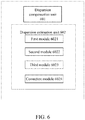
- the embodiment of the present invention further comprises a dispersion estimation device in optical coherent communication, as shown in FIG. 6 , comprising at lease one processer executing a dispersion compensation unit 601 and a dispersion estimation unit 602, wherein:
- the third module 6023 is configured to: for determining the mean value P ⁇ [n] of multiple groups of the data P [n], calculate an index n 0 of the maximum value of P ⁇ [n], and estimate the optical fiber link dispersion value based on the index n 0 of the maximum value.
- the abscissa in FIG. 3 represents the dispersion, as shown in FIG. 4 .
- the estimated dispersion value range is -162ns/nm to 162ns/nm.
- FIG. 5 is obtained by enlarging the local part of FIG. 4 .
- the dispersion value corresponding to the index 605 is 47994ps/nm
- the dispersion value corresponding to the corrected accurate index 605.0695 is 48000ps/nm. It demonstrates that the dispersion estimation accuracy in the embodiment of the present invention is very high.
- the dispersion estimation unit may further comprise a correction module 6024, and the correction module 6024 is configured to: after calculating the index n 0 of the maximum value of P ⁇ [n], use an interpolation equation to correct the index n 0 .
- n 0 ′ n 0 + P ⁇ n 0 ⁇ 1 ⁇ P ⁇ n 0 + 1 2 P ⁇ n 0 ⁇ 1 ⁇ 2 P ⁇ n 0 ⁇ P ⁇ n 0 + 1 ;
- the frequency-domain data in the two polarization directions obtained through the fast Fourier transform after the IQ-imbalance compensation may be obtained by the dispersion compensation unit performing the frequency domain fast convolution transform on the IQ-imbalance compensated data, or it may be obtained by the dispersion estimation unit using the FFT transform.
- a Fourier transform module can be provided in the dispersion estimation unit to use the FFT transform to obtain the frequency domain data in the two polarization directions.
- each module/unit in the abovementioned embodiments may be realized in a form of hardware, or in a form of software function modules.
- the present invention is not limited to any specific form of hardware and software combinations.
- the abovementioned technical solution can directly calculate the dispersion without searching, thus, when the system starts, the value of the link dispersion can be quickly estimated.
- it may also continue to estimate the link dispersion value, track its change, and ensure the dispersion compensation module to precisely compensate the dispersion. It can achieve precise dispersion compensation, and can reduce the complexity of the clock recovery module thereafter, and the like.
- the abovementioned technical solution can very accurately estimate the dispersion value, and the estimation speed is fast. Therefore, the present invention has very strong industrial applicability.
Claims (15)
- Procédé d'estimation de dispersion dans une communication cohérente optique, comprenant :l'exécution d'une transformée rapide de Fourier sur des données à déséquilibre IQ compensé pour obtenir des données de domaine de fréquence dans deux sens de polarisation ;le calcul respectif de séquences d'autocorrélation des données de domaine de fréquence dans les deux sens de polarisation pour obtenir des valeurs des deux séquences d'autocorrélation correspondant aux données de domaine de fréquence dans les deux sens de polarisation ;l'exécution respective de la transformée rapide inverse de Fourier sur les valeurs des deux séquences d'autocorrélation pour obtenir deux résultats de transformée inverse de Fourier ;le calcul respectif de carrés de module des deux résultats de transformée rapide inverse de Fourier pour obtenir deux résultats de carré de module ;l'ajout des deux résultats de carré de module pour obtenir une somme des résultats de carré de module P[n] ;pour une pluralité de données à déséquilibre IQ compensé, le calcul d'une pluralité de sommes des résultats de carré de module, le calcul de la moyenne de toutes les sommes des résultats de carré de module pour obtenir une fonction objective de dispersion P̃[n] ;le calcul d'un indice n0 d'une valeur maximale de la fonction objective de dispersion P̃[n], et l'estimation d'une valeur de dispersion de liaison de fibre optique sur la base de l'indice n0.
- Procédé d'estimation de dispersion selon la revendication 1, dans lequel l'étape de l'exécution d'une transformée rapide de Fourier sur des données à déséquilibre IQ compensé pour obtenir des données de domaine de fréquence dans deux sens de polarisation comprend :l'exécution respective de la transformée rapide de Fourier sur les deux données de polarisation à déséquilibre IQ compensé pour obtenir des données de domaine de fréquence X[k] et Y[k] dans deux sens de polarisation de la manière suivante, où k = 0, ..., Nfft - 1, k est un indice de fréquence, Nfft est un nombre de points de transformée de Fourier :le calcul d'un spectre de signaux non orthogonaux dans les deux sens de polarisation selon l'équation suivante pour obtenir les données de domaine de fréquence dans les deux sens de polarisation :


- Procédé d'estimation de dispersion selon la revendication 2, dans lequel l'étape de l'exécution d'une transformée rapide de Fourier sur des données à déséquilibre IQ compensé pour obtenir des données de domaine de fréquence dans deux sens de polarisation comprend :l'utilisation d'une transformée de convolution de domaine de fréquence ou d'une transformée rapide de Fourier pour obtenir les données de domaine de fréquence dans les deux sens de polarisation.
- Procédé d'estimation de dispersion selon la revendication 3, dans lequel
un intervalle de séquences d'autocorrélation des données de domaine de fréquence dans les deux sens de polarisation est un débit en bauds ;
l'étape du calcul de séquences d'autocorrélation des données de domaine de fréquence dans les deux sens de polarisation pour obtenir des valeurs des deux séquences d'autocorrélation correspondant aux données de domaine de fréquence dans les deux sens de polarisation comprend :selon l'équation suivante, le calcul de la séquence d'autocorrélation C1[k] du spectre X1[k] et de la séquence d'autocorrélation C2[k] du spectre X2[k] dans les données de domaine de fréquence dans les deux sens de polarisation :
- Procédé d'estimation de dispersion selon la revendication 4, dans lequel l'étape de l'exécution respective de la transformée rapide inverse de Fourier sur les valeurs des deux séquences d'autocorrélation pour obtenir deux résultats de transformée inverse de Fourier comprend :selon l'équation suivante, l'exécution respective de la transformée rapide inverse de Fourier sur les valeurs des deux séquences d'autocorrélation :

- Procédé d'estimation de dispersion selon la revendication 5, dans lequel l'étape de l'ajout des deux résultats de carré de module pour obtenir une somme des résultats de carré de module P[n] comprend :le calcul de la somme des résultats de carré de module selon l'équation suivante :

- Procédé d'estimation de dispersion selon la revendication 6, dans lequel, après le calcul de l'indice n0 de la valeur maximale de la fonction objective de dispersion P̃[n], le procédé comprend en outre :l'utilisation d'une équation d'interpolation pour corriger l'indice n0,et dans lequel l'étape de l'utilisation de l'équation d'interpolation pour corriger l'indice n0 comprend :la correction de l'indice n0 selon l'équation d'interpolation parabolique suivante pour obtenir un résultat corrigé :
 et dans lequel l'étape de l'estimation d'une valeur de dispersion de liaison de fibre optique sur la base de l'indice n0 de la valeur maximale comprend :le calcul de la valeur de dispersion de liaison de fibre CD selon l'équation suivante :
- Dispositif d'estimation de dispersion dans une communication cohérente optique, comprenant une unité de compensation de dispersion et une unité d'estimation de dispersion, dans lequel :l'unité de compensation de dispersion est configurée pour effectuer :l'exécution d'une compensation de déséquilibre sur une IQ, l'exécution d'une transformée rapide de Fourier sur des données à déséquilibre IQ compensé pour obtenir des données de domaine de fréquence dans deux sens de polarisation ;l'unité d'estimation de dispersion comprend un premier module, un deuxième module et un troisième module, dans lequel :le premier module est configuré pour effectuer : le calcul respectif de séquences d'autocorrélation des données de domaine de fréquence dans les deux sens de polarisation pour obtenir des valeurs des deux séquences d'autocorrélation correspondant aux données de domaine de fréquence dans les deux sens de polarisation ;le deuxième module est configuré pour effectuer : l'exécution respective de la transformée rapide inverse de Fourier sur les valeurs des deux séquences d'autocorrélation pour obtenir deux résultats de transformée inverse de Fourier ; le calcul respectif de carrés de module des deux résultats de transformée rapide inverse de Fourier pour obtenir deux résultats de carré de module ; l'ajout des deux résultats de carré de module pour obtenir une somme des résultats de carré de module P[n] ;le troisième module est configuré pour effectuer : pour une pluralité de données à déséquilibre IQ compensé, le calcul de la moyenne d'une pluralité de sommes obtenues des résultats de carré de module pour obtenir une fonction objective de dispersion P̃[n] ; le calcul d'un indice n0 d'une valeur maximale de la fonction objective de dispersion P̃[n] ; et l'estimation d'une valeur de dispersion de liaison de fibre optique sur la base de l'indice n0.
- Dispositif d'estimation de dispersion selon la revendication 8, dans lequel l'unité d'estimation de dispersion est configurée pour effectuer :l'exécution d'une transformée rapide de Fourier sur des données à déséquilibre IQ compensé pour obtenir des données de domaine de fréquence dans deux sens de polarisation de la manière suivante :l'exécution respective de la transformée rapide de Fourier sur les deux données de polarisation à déséquilibre IQ compensé pour obtenir des données de domaine de fréquence X[k] et Y[k] dans les deux sens de polarisation de la manière suivante, où k = 0, ..., Nfft - 1, k est un indice de fréquence, Nfft est un nombre de points de transformée de Fourier :le calcul d'un spectre de signaux non orthogonaux dans les deux sens de polarisation selon l'équation suivante pour obtenir les données de domaine de fréquence dans les deux sens de polarisation :


- Appareil d'estimation de dispersion selon la revendication 9, dans lequel le premier module est configuré pour effectuer calcul de séquences d'autocorrélation des données de domaine de fréquence dans les deux sens de polarisation pour obtenir des valeurs des deux séquences d'autocorrélation correspondant aux données de domaine de fréquence dans les deux sens de polarisation de la manière suivante :selon l'équation suivante, le calcul de la séquence d'autocorrélation C1[k] du spectre X1[k] et de la séquence d'autocorrélation C2[k] du spectre X2[k] dans les données de domaine de fréquence dans les deux sens de polarisation, dans lequel l'intervalle de séquences d'autocorrélation des données de domaine de fréquence est un débit en bauds :

- Dispositif d'estimation de dispersion selon la revendication 10, dans lequel le deuxième module est configuré pour effectuer l'exécution respective de la transformée rapide inverse de Fourier sur les valeurs des deux séquences d'autocorrélation pour obtenir deux résultats de transformée inverse de Fourier de la manière suivante :selon l'équation suivante, l'exécution respective de la transformée rapide inverse de Fourier sur les valeurs des deux séquences d'autocorrélation :

- Dispositif d'estimation de dispersion selon la revendication 11, dans lequel le deuxième module est configuré pour effectuer l'ajout des deux résultats de carré de module pour obtenir une somme des résultats de carré de module P[n] de la manière suivante :le calcul de la somme des résultats de carré de module P[n] selon l'équation suivante :

- Dispositif d'estimation de dispersion selon la revendication 12, dans lequel l'unité d'estimation de dispersion comprend en outre un module de correction, dans lequel :le module de correction est configuré pour effectuer : l'utilisation d'une équation d'interpolation pour corriger l'indice n0,et dans lequel le module de correction est configuré pour effectuer la correction de l'indice n0 selon l'équation d'interpolation parabolique suivante :
 où n0' est le résultat corrigé,et dans lequel le troisième module est configuré pour effectuer l'estimation d'une valeur de dispersion de liaison de fibre optique sur la base de l'indice n0 de la manière suivante :le calcul de la valeur de dispersion de liaison de fibre selon l'équation suivante :
- Dispositif d'estimation de dispersion selon l'une quelconque des revendications 8 à 13, dans lequel l'unité de compensation de dispersion est configurée pour effectuer l'exécution d'une transformée rapide de Fourier sur des données à déséquilibre IQ compensé pour obtenir des données de domaine de fréquence dans deux sens de polarisation de la manière suivante :l'utilisation d'une transformée de convolution de domaine de fréquence sur les données à déséquilibre IQ compensé pour obtenir les données de domaine de fréquence dans les deux sens de polarisation.
- Dispositif d'estimation de dispersion selon l'une quelconque des revendications 8 à 13, dans lequel l'unité d'estimation de dispersion comprend en outre :un module de transformée de Fourier qui utilise la transformée rapide de Fourier sur les données à déséquilibre IQ compensé pour obtenir des données de domaine de fréquence respectivement dans deux sens de polarisation.
Applications Claiming Priority (2)
| Application Number | Priority Date | Filing Date | Title |
|---|---|---|---|
| CN201310498534.7A CN104579476B (zh) | 2013-10-22 | 2013-10-22 | 光相干通信中色散估计方法及装置 |
| PCT/CN2014/078327 WO2014183699A1 (fr) | 2013-10-22 | 2014-05-23 | Procédé et dispositif pour une estimation de dispersion chromatique dans une communication cohérente optique |
Publications (3)
| Publication Number | Publication Date |
|---|---|
| EP3048746A1 EP3048746A1 (fr) | 2016-07-27 |
| EP3048746A4 EP3048746A4 (fr) | 2016-10-19 |
| EP3048746B1 true EP3048746B1 (fr) | 2018-11-21 |
Family
ID=51897758
Family Applications (1)
| Application Number | Title | Priority Date | Filing Date |
|---|---|---|---|
| EP14797641.9A Active EP3048746B1 (fr) | 2013-10-22 | 2014-05-23 | Procédé et dispositif pour une estimation de dispersion chromatique dans une communication cohérente optique |
Country Status (4)
| Country | Link |
|---|---|
| US (1) | US9729232B2 (fr) |
| EP (1) | EP3048746B1 (fr) |
| CN (1) | CN104579476B (fr) |
| WO (1) | WO2014183699A1 (fr) |
Families Citing this family (12)
| Publication number | Priority date | Publication date | Assignee | Title |
|---|---|---|---|---|
| CN104780131B (zh) * | 2014-01-15 | 2019-04-30 | 深圳市中兴微电子技术有限公司 | 一种色度色散测量方法、装置及数字相干接收机 |
| CN106656314B (zh) | 2015-10-31 | 2019-05-24 | 华为技术有限公司 | 一种监测光通信网络色散的方法及装置 |
| CN108226850B (zh) * | 2016-12-21 | 2021-11-09 | 中国航天科工集团八五一一研究所 | 一种基于抛物线拟合的单脉冲鉴相方法 |
| CN111262634B (zh) * | 2018-11-30 | 2020-11-17 | 深圳市中兴微电子技术有限公司 | 色散估计方法、装置、接收机及存储介质 |
| JP7111973B2 (ja) * | 2019-01-30 | 2022-08-03 | 日本電信電話株式会社 | 波長分散量推定装置 |
| EP3965319A4 (fr) * | 2019-06-06 | 2022-12-21 | Nippon Telegraph And Telephone Corporation | Dispositif de compensation de la dispersion des longueurs d'onde, dispositif de réception de la lumière, procédé de compensation de la dispersion des longueurs d'onde et programme informatique |
| CN112713941A (zh) * | 2019-10-24 | 2021-04-27 | 富士通株式会社 | 静态均衡器系数的确定装置及方法 |
| CN113676254B (zh) * | 2020-05-15 | 2022-06-28 | 华为技术有限公司 | 色散估计方法及装置 |
| CN113742088B (zh) * | 2021-09-23 | 2023-11-14 | 上海交通大学 | 用于处理射电望远镜数据的脉冲星搜索并行优化方法 |
| CN114172569B (zh) * | 2021-11-24 | 2023-03-17 | 武汉邮电科学研究院有限公司 | 一种基于相干光通信系统的光纤色散系数测量方法及装置 |
| CN114726450B (zh) * | 2022-04-07 | 2023-10-20 | 中山大学 | 一种色散容忍的时钟恢复方法及系统 |
| CN116032703B (zh) * | 2023-03-29 | 2023-06-27 | 中国人民解放军海军工程大学 | 一种变换域通信系统信号码元数量的估计方法及系统 |
Family Cites Families (11)
| Publication number | Priority date | Publication date | Assignee | Title |
|---|---|---|---|---|
| AU2003201483A1 (en) * | 2003-01-15 | 2004-08-10 | Telefonaktiebolaget Lm Ericsson (Publ) | Correlation method for channel estimation for ofdm |
| WO2008026178A2 (fr) * | 2006-08-31 | 2008-03-06 | Nxp B.V. | Estimation d'un déséquilibre i/q dépendant de la fréquence |
| KR101278025B1 (ko) * | 2009-10-15 | 2013-06-21 | 한국전자통신연구원 | 직교 주파수 분할 다중화 방식의 i/q 불균형 보상을 위한 수신 장치 및 그 수신 장치에서 수행되는 i/q 불균형 보상 방법 |
| BR112012010343B1 (pt) * | 2010-03-04 | 2021-04-13 | Huawei Technologies Co.,Ltd | Dispositivo de filtro e método de filtrar um sinal de entrada |
| US8767575B2 (en) * | 2010-08-06 | 2014-07-01 | Futurewei Technologies, Inc. | Method and apparatus for broadband carrier frequency and phase recovery in coherent optical system |
| WO2012109792A1 (fr) * | 2011-02-17 | 2012-08-23 | Huawei Technologies Co., Ltd. | Estimateur de dispersion chromatique et procédé d'estimation d'une dispersion chromatique |
| CN102655433B (zh) * | 2011-03-04 | 2016-03-30 | 富士通株式会社 | 非线性损伤补偿方法和装置 |
| CN103430003B (zh) * | 2012-02-01 | 2016-03-30 | 华为技术有限公司 | 用于估计接收到的光信号的色散的方法 |
| US8913901B2 (en) * | 2012-02-20 | 2014-12-16 | Tyco Electronics Subsea Communications Llc | System and method for blind equalization and carrier phase recovery in a quadrature amplitude modulated system |
| US9225431B1 (en) * | 2012-06-19 | 2015-12-29 | Juniper Networks, Inc. | Fast chromatic dispersion estimation |
| WO2014019211A1 (fr) * | 2012-08-03 | 2014-02-06 | 华为技术有限公司 | Système, dispositif et procédé d'estimation de dispersion chromatique |
-
2013
- 2013-10-22 CN CN201310498534.7A patent/CN104579476B/zh active Active
-
2014
- 2014-05-23 EP EP14797641.9A patent/EP3048746B1/fr active Active
- 2014-05-23 US US15/030,834 patent/US9729232B2/en active Active
- 2014-05-23 WO PCT/CN2014/078327 patent/WO2014183699A1/fr active Application Filing
Non-Patent Citations (1)
| Title |
|---|
| None * |
Also Published As
| Publication number | Publication date |
|---|---|
| EP3048746A1 (fr) | 2016-07-27 |
| US9729232B2 (en) | 2017-08-08 |
| EP3048746A4 (fr) | 2016-10-19 |
| CN104579476A (zh) | 2015-04-29 |
| US20160269108A1 (en) | 2016-09-15 |
| CN104579476B (zh) | 2018-09-28 |
| WO2014183699A1 (fr) | 2014-11-20 |
Similar Documents
| Publication | Publication Date | Title |
|---|---|---|
| EP3048746B1 (fr) | Procédé et dispositif pour une estimation de dispersion chromatique dans une communication cohérente optique | |
| US9686020B2 (en) | Signal processing device and signal processing method | |
| CA3047882C (fr) | Procede d'estimation de caracteristique d'emission optique, procede de compensation de caracteristique d'emission optique, systeme d'estimation de caracteristique d'emission optiq ue et systeme de compensation de caracteristique d'emission optique | |
| US9912500B2 (en) | Adaptive pre-equalization in optical communications | |
| US20110064421A1 (en) | Apparatus and method for equalizing chromatic dispersion and digital coherent optical receiver | |
| JP4886813B2 (ja) | デジタル信号処理回路 | |
| US9425900B2 (en) | Chromatic dispersion processing apparatus and method | |
| US9203508B2 (en) | Method for estimating a chromatic dispersion of a received optical signal | |
| EP3096469B1 (fr) | Procédé et dispositif de mesure de dispersion chromatique, et récepteur numérique cohérent | |
| CN107078982A (zh) | 数字相干光接收器的色散估计 | |
| US9369213B1 (en) | Demultiplexing processing for a receiver | |
| US20190393964A1 (en) | Clock recovery for subcarrier based coherent optical systems | |
| WO2013185845A1 (fr) | Procédé d'adaptation d'un égaliseur pour égaliser une caractéristique composite d'un canal de communication optique | |
| US10505641B2 (en) | Clock recovery for band-limited optical channels | |
| WO2016101541A1 (fr) | Dispositif, procédé et support de stockage informatique pour récupération d'horloge et égalisation | |
| US10903911B2 (en) | Apparatus and method for estimating polarization skew | |
| Zhao et al. | Independent component analysis for phase and residual frequency offset compensation in OQAM multicarrier systems | |
| EP3345314A1 (fr) | Extraction de phase pour la compensation d'interférence inter-symboles induite par une dispersion chromatique | |
| Huang et al. | Full-range carrier frequency offset estimation for CO-OFDM based on CMA equalizers | |
| JP6984784B2 (ja) | 光伝送特性推定方法、光伝送特性推定システム及び光伝送特性補償システム | |
| WO2022201387A1 (fr) | Dispositif d'estimation de décalages de fréquences, dispositif récepteur, procédé d'estimation de décalages de fréquences et programme | |
| WO2023152904A1 (fr) | Procédé de traitement de signal, dispositif de traitement de signal et système de communication | |
| WO2023152909A1 (fr) | Procédé de traitement de signal, dispositif de traitement de signal, et système de communication | |
| Ma et al. | A novel high precision adaptive equalizer in digital coherent optical receivers | |
| EP3133751A1 (fr) | Procédé de compensation de non-linéarité dans des systèmes de transmission optique |
Legal Events
| Date | Code | Title | Description |
|---|---|---|---|
| PUAI | Public reference made under article 153(3) epc to a published international application that has entered the european phase |
Free format text: ORIGINAL CODE: 0009012 |
|
| 17P | Request for examination filed |
Effective date: 20160421 |
|
| AK | Designated contracting states |
Kind code of ref document: A1 Designated state(s): AL AT BE BG CH CY CZ DE DK EE ES FI FR GB GR HR HU IE IS IT LI LT LU LV MC MK MT NL NO PL PT RO RS SE SI SK SM TR |
|
| AX | Request for extension of the european patent |
Extension state: BA ME |
|
| A4 | Supplementary search report drawn up and despatched |
Effective date: 20160921 |
|
| RIC1 | Information provided on ipc code assigned before grant |
Ipc: H04B 10/079 20130101AFI20160915BHEP Ipc: H04B 10/61 20130101ALI20160915BHEP |
|
| DAX | Request for extension of the european patent (deleted) | ||
| RAP1 | Party data changed (applicant data changed or rights of an application transferred) |
Owner name: SANECHIPS TECHNOLOGY CO., LTD. Owner name: ZTE CORPORATION |
|
| GRAP | Despatch of communication of intention to grant a patent |
Free format text: ORIGINAL CODE: EPIDOSNIGR1 |
|
| STAA | Information on the status of an ep patent application or granted ep patent |
Free format text: STATUS: GRANT OF PATENT IS INTENDED |
|
| RIC1 | Information provided on ipc code assigned before grant |
Ipc: H04B 10/61 20130101ALI20180529BHEP Ipc: H04B 10/079 20130101AFI20180529BHEP |
|
| INTG | Intention to grant announced |
Effective date: 20180615 |
|
| GRAS | Grant fee paid |
Free format text: ORIGINAL CODE: EPIDOSNIGR3 |
|
| GRAA | (expected) grant |
Free format text: ORIGINAL CODE: 0009210 |
|
| STAA | Information on the status of an ep patent application or granted ep patent |
Free format text: STATUS: THE PATENT HAS BEEN GRANTED |
|
| AK | Designated contracting states |
Kind code of ref document: B1 Designated state(s): AL AT BE BG CH CY CZ DE DK EE ES FI FR GB GR HR HU IE IS IT LI LT LU LV MC MK MT NL NO PL PT RO RS SE SI SK SM TR |
|
| REG | Reference to a national code |
Ref country code: CH Ref legal event code: EP |
|
| REG | Reference to a national code |
Ref country code: IE Ref legal event code: FG4D |
|
| REG | Reference to a national code |
Ref country code: DE Ref legal event code: R096 Ref document number: 602014036587 Country of ref document: DE |
|
| REG | Reference to a national code |
Ref country code: AT Ref legal event code: REF Ref document number: 1068777 Country of ref document: AT Kind code of ref document: T Effective date: 20181215 |
|
| REG | Reference to a national code |
Ref country code: NL Ref legal event code: MP Effective date: 20181121 |
|
| REG | Reference to a national code |
Ref country code: AT Ref legal event code: MK05 Ref document number: 1068777 Country of ref document: AT Kind code of ref document: T Effective date: 20181121 |
|
| PG25 | Lapsed in a contracting state [announced via postgrant information from national office to epo] |
Ref country code: LT Free format text: LAPSE BECAUSE OF FAILURE TO SUBMIT A TRANSLATION OF THE DESCRIPTION OR TO PAY THE FEE WITHIN THE PRESCRIBED TIME-LIMIT Effective date: 20181121 Ref country code: HR Free format text: LAPSE BECAUSE OF FAILURE TO SUBMIT A TRANSLATION OF THE DESCRIPTION OR TO PAY THE FEE WITHIN THE PRESCRIBED TIME-LIMIT Effective date: 20181121 Ref country code: NO Free format text: LAPSE BECAUSE OF FAILURE TO SUBMIT A TRANSLATION OF THE DESCRIPTION OR TO PAY THE FEE WITHIN THE PRESCRIBED TIME-LIMIT Effective date: 20190221 Ref country code: BG Free format text: LAPSE BECAUSE OF FAILURE TO SUBMIT A TRANSLATION OF THE DESCRIPTION OR TO PAY THE FEE WITHIN THE PRESCRIBED TIME-LIMIT Effective date: 20190221 Ref country code: FI Free format text: LAPSE BECAUSE OF FAILURE TO SUBMIT A TRANSLATION OF THE DESCRIPTION OR TO PAY THE FEE WITHIN THE PRESCRIBED TIME-LIMIT Effective date: 20181121 Ref country code: LV Free format text: LAPSE BECAUSE OF FAILURE TO SUBMIT A TRANSLATION OF THE DESCRIPTION OR TO PAY THE FEE WITHIN THE PRESCRIBED TIME-LIMIT Effective date: 20181121 Ref country code: ES Free format text: LAPSE BECAUSE OF FAILURE TO SUBMIT A TRANSLATION OF THE DESCRIPTION OR TO PAY THE FEE WITHIN THE PRESCRIBED TIME-LIMIT Effective date: 20181121 Ref country code: IS Free format text: LAPSE BECAUSE OF FAILURE TO SUBMIT A TRANSLATION OF THE DESCRIPTION OR TO PAY THE FEE WITHIN THE PRESCRIBED TIME-LIMIT Effective date: 20190321 Ref country code: AT Free format text: LAPSE BECAUSE OF FAILURE TO SUBMIT A TRANSLATION OF THE DESCRIPTION OR TO PAY THE FEE WITHIN THE PRESCRIBED TIME-LIMIT Effective date: 20181121 |
|
| PG25 | Lapsed in a contracting state [announced via postgrant information from national office to epo] |
Ref country code: PT Free format text: LAPSE BECAUSE OF FAILURE TO SUBMIT A TRANSLATION OF THE DESCRIPTION OR TO PAY THE FEE WITHIN THE PRESCRIBED TIME-LIMIT Effective date: 20190321 Ref country code: GR Free format text: LAPSE BECAUSE OF FAILURE TO SUBMIT A TRANSLATION OF THE DESCRIPTION OR TO PAY THE FEE WITHIN THE PRESCRIBED TIME-LIMIT Effective date: 20190222 Ref country code: SE Free format text: LAPSE BECAUSE OF FAILURE TO SUBMIT A TRANSLATION OF THE DESCRIPTION OR TO PAY THE FEE WITHIN THE PRESCRIBED TIME-LIMIT Effective date: 20181121 Ref country code: AL Free format text: LAPSE BECAUSE OF FAILURE TO SUBMIT A TRANSLATION OF THE DESCRIPTION OR TO PAY THE FEE WITHIN THE PRESCRIBED TIME-LIMIT Effective date: 20181121 Ref country code: NL Free format text: LAPSE BECAUSE OF FAILURE TO SUBMIT A TRANSLATION OF THE DESCRIPTION OR TO PAY THE FEE WITHIN THE PRESCRIBED TIME-LIMIT Effective date: 20181121 Ref country code: RS Free format text: LAPSE BECAUSE OF FAILURE TO SUBMIT A TRANSLATION OF THE DESCRIPTION OR TO PAY THE FEE WITHIN THE PRESCRIBED TIME-LIMIT Effective date: 20181121 |
|
| PG25 | Lapsed in a contracting state [announced via postgrant information from national office to epo] |
Ref country code: PL Free format text: LAPSE BECAUSE OF FAILURE TO SUBMIT A TRANSLATION OF THE DESCRIPTION OR TO PAY THE FEE WITHIN THE PRESCRIBED TIME-LIMIT Effective date: 20181121 Ref country code: DK Free format text: LAPSE BECAUSE OF FAILURE TO SUBMIT A TRANSLATION OF THE DESCRIPTION OR TO PAY THE FEE WITHIN THE PRESCRIBED TIME-LIMIT Effective date: 20181121 Ref country code: IT Free format text: LAPSE BECAUSE OF FAILURE TO SUBMIT A TRANSLATION OF THE DESCRIPTION OR TO PAY THE FEE WITHIN THE PRESCRIBED TIME-LIMIT Effective date: 20181121 Ref country code: CZ Free format text: LAPSE BECAUSE OF FAILURE TO SUBMIT A TRANSLATION OF THE DESCRIPTION OR TO PAY THE FEE WITHIN THE PRESCRIBED TIME-LIMIT Effective date: 20181121 |
|
| REG | Reference to a national code |
Ref country code: DE Ref legal event code: R097 Ref document number: 602014036587 Country of ref document: DE |
|
| PG25 | Lapsed in a contracting state [announced via postgrant information from national office to epo] |
Ref country code: SK Free format text: LAPSE BECAUSE OF FAILURE TO SUBMIT A TRANSLATION OF THE DESCRIPTION OR TO PAY THE FEE WITHIN THE PRESCRIBED TIME-LIMIT Effective date: 20181121 Ref country code: SM Free format text: LAPSE BECAUSE OF FAILURE TO SUBMIT A TRANSLATION OF THE DESCRIPTION OR TO PAY THE FEE WITHIN THE PRESCRIBED TIME-LIMIT Effective date: 20181121 Ref country code: EE Free format text: LAPSE BECAUSE OF FAILURE TO SUBMIT A TRANSLATION OF THE DESCRIPTION OR TO PAY THE FEE WITHIN THE PRESCRIBED TIME-LIMIT Effective date: 20181121 Ref country code: RO Free format text: LAPSE BECAUSE OF FAILURE TO SUBMIT A TRANSLATION OF THE DESCRIPTION OR TO PAY THE FEE WITHIN THE PRESCRIBED TIME-LIMIT Effective date: 20181121 |
|
| PLBE | No opposition filed within time limit |
Free format text: ORIGINAL CODE: 0009261 |
|
| STAA | Information on the status of an ep patent application or granted ep patent |
Free format text: STATUS: NO OPPOSITION FILED WITHIN TIME LIMIT |
|
| 26N | No opposition filed |
Effective date: 20190822 |
|
| PG25 | Lapsed in a contracting state [announced via postgrant information from national office to epo] |
Ref country code: SI Free format text: LAPSE BECAUSE OF FAILURE TO SUBMIT A TRANSLATION OF THE DESCRIPTION OR TO PAY THE FEE WITHIN THE PRESCRIBED TIME-LIMIT Effective date: 20181121 |
|
| REG | Reference to a national code |
Ref country code: DE Ref legal event code: R119 Ref document number: 602014036587 Country of ref document: DE |
|
| REG | Reference to a national code |
Ref country code: CH Ref legal event code: PL |
|
| PG25 | Lapsed in a contracting state [announced via postgrant information from national office to epo] |
Ref country code: LI Free format text: LAPSE BECAUSE OF NON-PAYMENT OF DUE FEES Effective date: 20190531 Ref country code: MC Free format text: LAPSE BECAUSE OF FAILURE TO SUBMIT A TRANSLATION OF THE DESCRIPTION OR TO PAY THE FEE WITHIN THE PRESCRIBED TIME-LIMIT Effective date: 20181121 Ref country code: CH Free format text: LAPSE BECAUSE OF NON-PAYMENT OF DUE FEES Effective date: 20190531 |
|
| REG | Reference to a national code |
Ref country code: BE Ref legal event code: MM Effective date: 20190531 |
|
| PG25 | Lapsed in a contracting state [announced via postgrant information from national office to epo] |
Ref country code: LU Free format text: LAPSE BECAUSE OF NON-PAYMENT OF DUE FEES Effective date: 20190523 |
|
| PG25 | Lapsed in a contracting state [announced via postgrant information from national office to epo] |
Ref country code: TR Free format text: LAPSE BECAUSE OF FAILURE TO SUBMIT A TRANSLATION OF THE DESCRIPTION OR TO PAY THE FEE WITHIN THE PRESCRIBED TIME-LIMIT Effective date: 20181121 |
|
| PG25 | Lapsed in a contracting state [announced via postgrant information from national office to epo] |
Ref country code: IE Free format text: LAPSE BECAUSE OF NON-PAYMENT OF DUE FEES Effective date: 20190523 Ref country code: DE Free format text: LAPSE BECAUSE OF NON-PAYMENT OF DUE FEES Effective date: 20191203 |
|
| PG25 | Lapsed in a contracting state [announced via postgrant information from national office to epo] |
Ref country code: BE Free format text: LAPSE BECAUSE OF NON-PAYMENT OF DUE FEES Effective date: 20190531 |
|
| PG25 | Lapsed in a contracting state [announced via postgrant information from national office to epo] |
Ref country code: CY Free format text: LAPSE BECAUSE OF FAILURE TO SUBMIT A TRANSLATION OF THE DESCRIPTION OR TO PAY THE FEE WITHIN THE PRESCRIBED TIME-LIMIT Effective date: 20181121 |
|
| PG25 | Lapsed in a contracting state [announced via postgrant information from national office to epo] |
Ref country code: HU Free format text: LAPSE BECAUSE OF FAILURE TO SUBMIT A TRANSLATION OF THE DESCRIPTION OR TO PAY THE FEE WITHIN THE PRESCRIBED TIME-LIMIT; INVALID AB INITIO Effective date: 20140523 Ref country code: MT Free format text: LAPSE BECAUSE OF FAILURE TO SUBMIT A TRANSLATION OF THE DESCRIPTION OR TO PAY THE FEE WITHIN THE PRESCRIBED TIME-LIMIT Effective date: 20181121 |
|
| PG25 | Lapsed in a contracting state [announced via postgrant information from national office to epo] |
Ref country code: MK Free format text: LAPSE BECAUSE OF FAILURE TO SUBMIT A TRANSLATION OF THE DESCRIPTION OR TO PAY THE FEE WITHIN THE PRESCRIBED TIME-LIMIT Effective date: 20181121 |
|
| REG | Reference to a national code |
Ref country code: FR Ref legal event code: PLFP Year of fee payment: 10 |
|
| REG | Reference to a national code |
Ref country code: GB Ref legal event code: 732E Free format text: REGISTERED BETWEEN 20230420 AND 20230426 |
|
| PGFP | Annual fee paid to national office [announced via postgrant information from national office to epo] |
Ref country code: GB Payment date: 20230330 Year of fee payment: 10 |
|
| PGFP | Annual fee paid to national office [announced via postgrant information from national office to epo] |
Ref country code: FR Payment date: 20230411 Year of fee payment: 10 |