EP3048556B1 - Verstellvorrichtung für ein optisches element - Google Patents
Verstellvorrichtung für ein optisches element Download PDFInfo
- Publication number
- EP3048556B1 EP3048556B1 EP15195862.6A EP15195862A EP3048556B1 EP 3048556 B1 EP3048556 B1 EP 3048556B1 EP 15195862 A EP15195862 A EP 15195862A EP 3048556 B1 EP3048556 B1 EP 3048556B1
- Authority
- EP
- European Patent Office
- Prior art keywords
- cam disk
- optical element
- wheel
- optoelectronic sensor
- adjustment device
- Prior art date
- Legal status (The legal status is an assumption and is not a legal conclusion. Google has not performed a legal analysis and makes no representation as to the accuracy of the status listed.)
- Active
Links
Images
Classifications
-
- G—PHYSICS
- G02—OPTICS
- G02B—OPTICAL ELEMENTS, SYSTEMS OR APPARATUS
- G02B7/00—Mountings, adjusting means, or light-tight connections, for optical elements
- G02B7/02—Mountings, adjusting means, or light-tight connections, for optical elements for lenses
- G02B7/04—Mountings, adjusting means, or light-tight connections, for optical elements for lenses with mechanism for focusing or varying magnification
-
- G—PHYSICS
- G03—PHOTOGRAPHY; CINEMATOGRAPHY; ANALOGOUS TECHNIQUES USING WAVES OTHER THAN OPTICAL WAVES; ELECTROGRAPHY; HOLOGRAPHY
- G03B—APPARATUS OR ARRANGEMENTS FOR TAKING PHOTOGRAPHS OR FOR PROJECTING OR VIEWING THEM; APPARATUS OR ARRANGEMENTS EMPLOYING ANALOGOUS TECHNIQUES USING WAVES OTHER THAN OPTICAL WAVES; ACCESSORIES THEREFOR
- G03B3/00—Focusing arrangements of general interest for cameras, projectors or printers
- G03B3/10—Power-operated focusing
-
- G—PHYSICS
- G02—OPTICS
- G02B—OPTICAL ELEMENTS, SYSTEMS OR APPARATUS
- G02B7/00—Mountings, adjusting means, or light-tight connections, for optical elements
- G02B7/02—Mountings, adjusting means, or light-tight connections, for optical elements for lenses
- G02B7/04—Mountings, adjusting means, or light-tight connections, for optical elements for lenses with mechanism for focusing or varying magnification
- G02B7/08—Mountings, adjusting means, or light-tight connections, for optical elements for lenses with mechanism for focusing or varying magnification adapted to co-operate with a remote control mechanism
-
- H—ELECTRICITY
- H04—ELECTRIC COMMUNICATION TECHNIQUE
- H04N—PICTORIAL COMMUNICATION, e.g. TELEVISION
- H04N23/00—Cameras or camera modules comprising electronic image sensors; Control thereof
- H04N23/50—Constructional details
- H04N23/55—Optical parts specially adapted for electronic image sensors; Mounting thereof
-
- G—PHYSICS
- G02—OPTICS
- G02B—OPTICAL ELEMENTS, SYSTEMS OR APPARATUS
- G02B7/00—Mountings, adjusting means, or light-tight connections, for optical elements
- G02B7/28—Systems for automatic generation of focusing signals
- G02B7/36—Systems for automatic generation of focusing signals using image sharpness techniques, e.g. image processing techniques for generating autofocus signals
Definitions
- the invention relates to an optoelectronic sensor with an optical element and an adjustment device for the optical element according to the preamble of claim 1.
- motor-driven optical elements are required.
- An important example is a focus adjustment, by which lenses or objectives are moved in order to bundle a transmitted beam or to take sharp pictures over a required working area. This is usually combined with an autofocus, in which the distance to the relevant object is determined and the focus position is set accordingly.
- a known focus adjustment uses an eccentric unit on which an eccentrically mounted ball bearing rolls, for example on a steel shaft.
- the adjustment uses a maximum of half a rotation.
- the adjustment path is therefore limited to half a revolution, the edge areas are unusable because the resolution is too low.
- cams with a linear gradient over the full revolution can therefore be used.
- the adjustment movement takes place via a rolling ball bearing on the cam.
- Such a focus adjustment in which an objective can be moved in a parallel guide by a cam, is from the EP 2 498 113 B1 known.
- this cam is produced as a plastic injection-molded part and therefore becomes the component that limits the service life.
- the adjusting device uses a cam disk and a transmission element which is in contact with its periphery. Since the cam has a radius that varies over the circumference, in particular rising linearly, it generates a linear adjustment movement during a rotary movement which acts on the optical element through the transmission element.
- the invention is based on the basic idea of producing the cam disk from metal. This is achieved very precisely and simply by means of an etching technique.
- a corresponding manufacturing method is defined in claim 8.
- the invention has the advantage that the cam is very robust and durable. At the same time, the cam provides the transmission element with an extremely smooth rolling edge. By means of etching technology, the cam disk can be manufactured precisely and, above all, very inexpensively in comparison with other metalworking techniques. In the case of CNC (Computerized Numerical Control) production, for example, despite the high production costs, a cam disc would arise that is heavier and has a poorer roll-off quality. The invention thus succeeds in combining the long service life of a ball bearing rolling on a steel shaft with the significantly better adjustability via a cam disk without significantly changing the manufacturing costs.
- CNC Computerized Numerical Control
- the cam is preferably made of hardened steel. This makes the cam disk particularly robust and durable.
- the transmission element preferably has a ball bearing.
- the ball bearing rolls on the etched edge, which is particularly smooth.
- the adjusting device thus functions with great precision over very long periods of time.
- the cam disk has a first wheel in contact with the transmission element and a second wheel which is connected to the first wheel and is designed as a spoked wheel.
- This two-part cam uses the first wheel to convert the rotary movement into an adjustment movement on its circumference.
- a second wheel is connected to the drive. This results in greater freedom of design for the first wheel, since it itself does not need a connection to a shaft in its center.
- Both wheels can be made of metal by etching technology and then connected to one another, for example by means of laser welding.
- the second wheel can be made of a different metal than the first wheel, for example a non-hardened steel, since it is not mechanically stressed by the transmission element.
- the first wheel is preferably designed as a ring, and the transmission element has a bearing and a counter bearing which are in contact with the first wheel on the outside and inside.
- the first wheel thus has a free interior space in which a counter bearing can move. This is possible because the bearing is in the middle of the cam on a shaft of the drive via the second wheel.
- the bearing and the counter bearing are preferably opposite one another perpendicular to the slope of the cam disk.
- the adjustment device is preferably a focus adjustment and the optical element is an objective.
- the position of an objective or at least one lens is therefore adjusted. This is a particularly frequent function of an optoelectronic sensor with a motor-driven part, which is thus fulfilled precisely and robustly.
- a camera with an adjusting device which has an image sensor, in the optical axis of which a lens with the optical element is arranged downstream, so that the lens can be adjusted in its focus position when the drive is actuated by moving the cam disk.
- the camera is even more preferably designed as a camera-based code reader and has an evaluation unit which is designed to read and output code information of a recorded code from image data of the image sensor.
- Camera-based code readers are particularly dependent on sharp images in order to capture the complete code information.
- rapid and frequent focus adjustment is required in usual applications, so that the robust, fast and precise focusing achieved with the invention over a large number of adjustment cycles is particularly well suited.
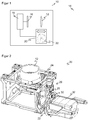
- Figure 1 shows a very simplified block diagram of a camera 10. Via an objective 12, which is only represented by a simple lens, light is guided from a scenery 14 to an image sensor 16 and passed on from there to an evaluation unit 18 in the form of electrical image data. In order to focus the camera 10 at a certain distance, a focus adjustment unit 20 is provided, which is controlled by the evaluation unit 18.
- the focus adjustment unit 20 has a cam disk 22, the rotational movement of which is mechanically translated into a linear adjustment movement of the lens 12.
- the cam disk 22 has to withstand very long operating times and a large number of adjustment cycles and is therefore manufactured using etching technology with its high accuracy in the production of hardened sheet steel parts of any contours.
- the etching technique as such is known and is not the subject of this application, but has so far not been used for gear elements rolling on ball bearings for adjusting optical components in optoelectronic sensors.
- the camera 10 with the focus adjustment 20 serves only as an example of an optical element that is moved by a motor. Focussing on the transmission side or the movement of another optical element, for example a vibrating mirror, are also conceivable.
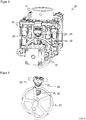
- Figures 2 to 4 show a possible embodiment of a focus adjustment unit 2 for a camera 10
- Figure 2 a three-dimensional overall view from diagonally above, Figure 3 but now a further three-dimensional view of the cam disk 22 and from the front Figure 4 a partial view similar Figure 3 but with the fading out of elements.
- the objective 12 is mounted in a parallel guide 24 in the focus adjustment unit 20.
- the objective 12 can be moved up and down in the parallel guide 24 for setting a desired focus position by means of a transmission element 26.
- the transmission element 26 has a ball bearing 28, which rolls on the outside of the cam disk 22, as well as a counter bearing 30.
- a rotary movement of the cam disk 22 generated by a drive 32, for example a stepping motor, is thus transferred into a translational movement of the objective 12 with a parallel displacement of the objective plane.
- the cam disk 22 runs without play in a double ball bearing made up of ball bearings 28 and counter bearings 30.
- the counter bearing 30 absorbs the force of the ball bearing 28 and a possible suspension with which the ball bearing 28 is pressed onto the cam disk 22 to achieve freedom from play , and thus derives it from a shaft of the drive 32.
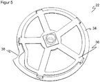
- Figure 5 shows the cam disk 22 again alone in a three-dimensional view.
- the cam disk 22 is constructed in two parts as a combination of parts produced by etching technology.
- a first wheel 34 has the actual contour of the cam disk 22 with a radius that varies in a desired manner over the circumference.
- the first wheel 34 is, however, constructed in the shape of a ring, that is to say has no material inside.
- the ball bearing 28 can roll on the outside of the first wheel 34 and the counter bearing 30 can roll on the inside.
- the storage on a shaft of the drive 32 takes place with the aid of a second wheel 36, which is designed, for example, as a spoked wheel and is also produced by etching technology.
- the connection of the two wheels 34, 36 can be done by means of laser welding.
- the cam disk 22, in particular its first wheel 34, preferably has a uniform, constant gradient over the entire circumference. A linear transmission between the rotary movement of the cam disk 22 and the displacement of the objective 12 can thus be achieved. In a comparatively very steep transition region 38, the radius is returned to the initial value after one revolution.
- cam disk 22 By producing the cam disk 22 using the etching technique, a smooth etched edge results, on which the ball bearing 28 or counter bearing 30 rolls, which is jerk-free and with is comparable to a ground straight pin.
- other cam disks 22 with different gradient behavior can be implemented cost-effectively. Unlike, for example, a conventional cam disk in injection molding technology, no new tool is required for this. Due to the thin design of the cam disk 22, which forms a linear bearing surface on the ball bearing 28 or counter bearing 30, no dirt particles can be deposited at the contact points on the running surface.
Landscapes
- Physics & Mathematics (AREA)
- General Physics & Mathematics (AREA)
- Optics & Photonics (AREA)
- Engineering & Computer Science (AREA)
- Multimedia (AREA)
- Signal Processing (AREA)
- Lens Barrels (AREA)
Description
- Die Erfindung betrifft einen optoelektronischen Sensor mit einem optischen Element und einer Verstellvorrichtung für das optisches Element nach dem Oberbegriff von Anspruch 1.
- Für manche Anpassungen optoelektronischer Sensoren werden motorisch bewegte optische Elemente benötigt. Ein wichtiges Beispiel ist eine Fokusverstellung, von der Linsen oder Objektive bewegt werden, um einen Sendestrahl zu bündeln oder Bilder über einen geforderten Arbeitsbereich hinweg scharf aufzunehmen. Meistens wird das mit einem Autofokus verbunden, bei dem der Abstand zu dem relevanten Objekt bestimmt und die Fokuslage entsprechend eingestellt wird.
- Eine bekannte Fokusverstellung verwendet eine Exzentereinheit, auf der ein exzentrisch gelagertes Kugellager beispielsweise auf eine Stahlwelle abrollt. Dabei nutzt die Verstellung höchstens die Hälfte einer Umdrehung. Bei Antrieb mit einem Schrittmotor ist der Verstellweg deshalb auf eine halbe Umdrehung begrenzt, die Randbereiche sind wegen zu geringer Auflösung unbrauchbar.
- Zur Erhöhung der Verstellgenauigkeit pro Schritt können deshalb Kurvenscheiben mit einer linearen Steigung über die volle Umdrehung eingesetzt werden. Die Verstellbewegung erfolgt über ein abrollendes Kugellager auf der Kurvenscheibe. Eine derartige Fokusverstellung, in der ein Objektiv in einer Parallelführung von einer Kurvenscheibe verfahren werden kann, ist aus der
EP 2 498 113 B1 bekannt. Diese Kurvenscheibe wird aber aus Kostengründen als Kunststoffspritzteil hergestellt und wird daher zu der lebensdauerbegrenzenden Komponente. - Es ist daher Aufgabe der Erfindung, eine verbesserte Verstellvorrichtung für ein optisches Element anzugeben.
- Diese Aufgabe wird durch einen optoelektronischen Sensor nach Anspruch 1 gelöst. Die Verstellvorrichtung nutzt eine Kurvenscheibe und ein Übertragungselement, das mit deren Umfang in Berührung steht. Da die Kurvenscheibe einen über den Umfang variierenden Radius aufweist, insbesondere linear ansteigend, erzeugt sie während einer Drehbewegung eine lineare Verstellbewegung, die durch das Übertragungselement auf das optische Element wirkt. Die Erfindung geht von dem Grundgedanken aus, die Kurvenscheibe aus Metall herzustellen. Dies wird sehr präzise und einfach durch eine ätztechnische Herstellung erreicht.
- Ein entsprechendes Herstellungsverfahren ist in Anspruch 8 definiert.
- Die Erfindung hat den Vorteil, dass die Kurvenscheibe sehr robust und langlebig ist. Zugleich bietet die Kurvenscheibe dem Übertragungselement eine außerordentlich glatte Abrollkante. Mittels Ätztechnik kann die Kurvenscheibe präzise und vor allem im Vergleich mit anderen Techniken zur Metallbearbeitung sehr kostengünstig hergestellt werden. Bei einer CNC-Herstellung (Computerized Numerical Control) etwa würde trotz der hohen Herstellkosten eine Kurvenscheibe entstehen, die schwerer ist und eine schlechtere Abrollqualität hat. So gelingt es der Erfindung, die hohe Lebensdauer eines auf einer Stahlwelle abrollenden Kugellagers mit der deutlich besseren Verstellbarkeit über eine Kurvenscheibe zu verbinden, ohne die Herstellkosten wesentlich zu verändern.
- Die Kurvenscheibe ist vorzugsweise aus gehärtetem Stahl hergestellt. Dadurch ist die Kurvenscheibe besonders widerstandsfähig und langlebig.
- Das Übertragungselement weist vorzugsweise ein Kugellager auf. Das Kugellager rollt auf der Ätzkante ab, die besonders glatt ist. Damit funktioniert die Verstellvorrichtung über sehr lange Zeiträume mit großer Präzision.
- Die Kurvenscheibe weist gemäß der Erfindung ein erstes Rad in Berührung mit dem Ubertragungselement und ein mit dem ersten Rad verbundenes zweites Rad auf, das als Speichenrad ausgebildet ist. Diese zweiteilige Kurvenscheibe nutzt das erste Rad, um an dessen Umfang die Drehbewegung in eine Verstellbewegung umzusetzen. Ein zweites Rad steht mit dem Antrieb in Verbindung. Dadurch ergibt sich eine größere Gestaltungsfreiheit für das erste Rad, da es selbst keine Verbindung zu einer Welle in seinem Mittelpunkt benötigt. Beide Räder können ätztechnisch aus Metall hergestellt und anschließend beispielsweise mittels Laserschweißen untereinander verbunden werden. Das zweite Rad kann aus einem anderen Metall hergestellt werden als das erste Rad, beispielsweise einem nicht gehärteten Stahl, da es nicht durch das Übertragungselement mechanisch belastet wird.
- Das erste Rad ist vorzugsweise als Ring ausgebildet, und das Übertragungselement weist ein Lager und ein Gegenlager auf, die außen und innen mit dem ersten Rad in Berührung stehen. Das erste Rad hat also einen freien Innenraum, in dem sich ein Gegenlager bewegen kann. Das ist möglich, weil die Lagerung in der Mitte der Kurvenscheibe an einer Welle des Antriebs über das zweite Rad erfolgt. Vorzugsweise stehen Lager und Gegenlager einander senkrecht zur Steigung der Kurvenscheibe gegenüber.
- Die Verstellvorrichtung ist vorzugsweise eine Fokusverstellung und das optische Element ein Objektiv. Es wird also die Position eines Objektivs beziehungsweise mindestens einer Linse verstellt. Dies ist eine besonders häufige Funktion eines optoelektronischen Sensors mit einem motorisch bewegten Teil, die somit präzise und robust erfüllt wird.
- In bevorzugter Weiterbildung ist eine Kamera mit einer erfindungsgemäßen Verstellvorrichtung vorgesehen, die einen Bildsensor aufweist, in dessen optischer Achse ein Objektiv mit dem optischen Element nachgeordnet ist, so dass bei Betätigung des Antriebs durch Bewegung der Kurvenscheibe das Objektiv in seiner Fokuslage einstellbar ist. Die Kamera ist noch bevorzugter als kamerabasierter Codeleser ausgebildet und weist eine Auswertungseinheit auf, die dafür ausgebildet ist, aus Bilddaten des Bildsensors eine Codeinformation eines aufgenommenen Codes auszulesen und auszugeben. Kamerabasierte Codeleser sind in besonderem Maße auf scharfe Bilder angewiesen, um die vollständige Codeinformation zu erfassen. Zugleich wird in üblichen Anwendungen eine rasche und häufige Fokusverstellung erforderlich, so dass sich die mit der Erfindung erreichte robuste, schnelle und genaue Fokussierung über eine große Zahl von Verstellzyklen besonders gut eignet.
- Die Erfindung wird nachstehend auch hinsichtlich weiterer Merkmale und Vorteile beispielhaft anhand von Ausführungsformen und unter Bezug auf die beigefügte Zeichnung näher erläutert. Die Abbildungen der Zeichnung zeigen in:
- Fig. 1
- eine vereinfachte Blockdarstellung einer Kamera mit Fokusverstellung;
- Fig. 2
- eine dreidimensionale Ansicht einer beispielhaften Fokusverstellung mit Kurvenscheibe;
- Fig. 3
- eine Ansicht gemäß
Figur 2 aus anderer Perspektive in Draufsicht auf die Kurvenscheibe; - Fig. 4
- eine Ansicht ähnlich
Figur 3 , jedoch unter Ausblendung von Elementen außer der Kurvenscheibe und darauf abrollender Kugellager eines Übertragungselements; und - Fig. 5
- eine dreidimensionale Ansicht einer Kurvenscheibe.
-
Figur 1 zeigt eine sehr vereinfachte Blockdarstellung einer Kamera 10. Über ein Objektiv 12, das nur durch eine einfache Linse dargestellt ist, wird Licht aus einer Szenerie 14 auf einen Bildsensor 16 geführt und von dort in Form von elektrischen Bilddaten an eine Auswertungseinheit 18 weitergegeben. Um die Kamera 10 auf eine bestimmte Entfernung scharf zu stellen, ist eine Fokusverstelleinheit 20 vorgesehen, welche von der Auswertungseinheit 18 angesteuert wird. - Eine beispielhafte Ausführungsform einer Fokusverstelleinheit 20 mit einer Kurvenscheibe wird weiter unten unter Bezugnahme auf die
Figuren 2 bis 4 näher erläutert. Die Fokusverstelleinheit 20 weist eine Kurvenscheibe 22 auf, deren Drehbewegung mechanisch in eine lineare Verstellbewegung des Objektivs 12 übersetzt wird. - Dabei muss die Kurvenscheibe 22 sehr langen Betriebsdauern und einer Vielzahl von Verstellzyklen standhalten und ist deshalb in Ätztechnik mit deren hoher Genauigkeit in der Herstellung von gehärteten Stahlblechteilen beliebiger Konturen gefertigt. Die Ätztechnik als solche ist bekannt und nicht Gegenstand dieser Anmeldung, wurde jedoch bisher nicht für sich auf Kugellager abrollende Getriebeelemente zur Verstellung von optischen Komponenten in optoelektronischen Sensoren eingesetzt.
- Die Kamera 10 mit der Fokusverstellung 20 dient nur als Beispiel für ein motorisch bewegtes optisches Element. Denkbar sind auch eine sendeseitige Fokussierung oder die Bewegung eines anderen optischen Elements, etwa eines Schwingspiegels.
- Die
Figuren 2 bis 4 zeigen eine mögliche Ausführungsform einer Fokusverstelleinheit 2 für eine Kamera 10. Dabei istFigur 2 eine dreidimensionale Gesamtansicht von schräg oben,Figur 3 eine weitere dreidimensionale Ansicht nun aber frontal auf die Kurvenscheibe 22 undFigur 4 eine Teilansicht ähnlichFigur 3 jedoch unter Ausblendung von Elementen. - In der Fokusverstelleinheit 20 ist das Objektiv 12 in einer Parallelführung 24 gelagert. Das Objektiv 12 kann in der Parallelführung 24 zur Einstellung einer gewünschten Fokuslage mittels eines Übertragungselements 26 auf und ab bewegt werden. Das Übertragungselement 26 weist ein Kugellager 28, das außen auf der Kurvenscheibe 22 abrollt, sowie ein Gegenlager 30 auf. Eine von einem Antrieb 32, beispielsweise einem Schrittmotor erzeugte Drehbewegung der Kurvenscheibe 22 überträgt sich somit in eine Translationsbewegung des Objektivs 12 unter Parallelverschiebung der Objektivebene.
- Wie am besten in
Figur 4 zu erkennen, läuft die Kurvenscheibe 22 spielfrei in einer doppelten Kugellagerung aus Kugellager 28 und Gegenlager 30. Dabei nimmt das Gegenlager 30 die Kraft des Kugellagers 28 und einer möglichen Federung auf, mit der das Kugellager 28 zum Erreichen der Spielfreiheit auf die Kurvenscheibe 22 gedrückt wird, und leitet sie somit von einer Welle des Antriebs 32 ab. -
Figur 5 zeigt die Kurvenscheibe 22 nochmals allein in einer dreidimensionalen Ansicht. Um eine Rotation der Kurvenscheibe 22 auch bei Einsatz des Gegenlagers 30 zu ermöglichen, ist die Kurvenscheibe 22 zweiteilig als Kombination von ätztechnisch hergestellten Teilen aufgebaut. Ein erstes Rad 34 weist die eigentliche Kontur der Kurvenscheibe 22 mit einem über den Umfang in gewünschter Weise variierenden Radius auf. Das erste Rad 34 ist jedoch ringförmig aufgebaut, weist also im Inneren kein Material auf. Dadurch kann außen auf dem ersten Rad 34 das Kugellager 28 und innen das Gegenlager 30 abrollen. Die Lagerung auf einer Welle des Antriebs 32 erfolgt mit Hilfe eines zweiten Rads 36, das beispielsweise als Speichenrad ausgebildet und ebenfalls ätztechnisch hergestellt ist. Die Verbindung der beiden Räder 34, 36 kann mittels Laserschweißen erfolgen. - Die Kurvenscheibe 22, insbesondere deren erstes Rad 34, weist vorzugsweise eine gleichmäßige, konstante Steigung über den gesamten Umfang auf. Damit kann eine lineare Übertragung zwischen Drehbewegung der Kurvenscheibe 22 und Verschiebung des Objektivs 12 erreicht werden. In einem vergleichsweise sehr steilen Übergangsbereich 38 wird der Radius nach einer Umdrehung auf den Ausgangswert zurückgeführt.
- Durch Herstellung der Kurvenscheibe 22 in Ätztechnik ergibt sich eine glatte Ätzkante, auf der das Kugellager 28 beziehungsweise Gegenlager 30 abrollt, die ruckfrei und mit einem geschliffenen Zylinderstift vergleichbar ist. Außerdem lassen sich kostengünstig andere Kurvenscheiben 22 mit unterschiedlichem Steigungsverhalten realisieren. Dazu ist, anders als beispielsweise bei einer herkömmlichen Kurvenscheibe in Spritzgusstechnik, kein neues Werkzeug erforderlich. Durch die dünne Ausführung der Kurvenscheibe 22, die eine linienförmige Auflagefläche auf dem Kugellager 28 beziehungsweise Gegenlager 30 bildet, können sich keine Schmutzpartikel an den Kontaktstellen auf der Lauffläche ablagern.
Claims (8)
- Optoelektronischer Sensor (10) mit einem optischen Element (12) und einer Verstellvorrichtung (20) für das optische Element (12), wobei die Verstellvorrichtung (20) einen Antrieb (32), eine von dem Antrieb (32) drehbare Kurvenscheibe (22) sowie ein Übertragungselement (26) aufweist, das mit einem Umfang der Kurvenscheibe (22) in Berührung steht und mit dem optischen Element (12) verbunden ist, um so eine Drehbewegung der Kurvenscheibe (22) in eine Verstellbewegung des optischen Elements (12) umzusetzen,
dadurch gekennzeichnet,
dass die Kurvenscheibe (22) in Ätztechnik aus Metall hergestellt ist und dass die Kurvenscheibe (22) ein erstes Rad (34) in Berührung mit dem Übertragungselement (26) und ein mit dem ersten Rad (34) verbundenes zweites Rad (36) aufweist, das als Speichenrad ausgebildet ist. - Optoelektronischer Sensor (10) nach Anspruch 1,
wobei die Kurvenscheibe (22) aus gehärtetem Stahl hergestellt ist. - Optoelektronischer Sensor (10) nach Anspruch 1 oder 2,
wobei das Übertragungselement (26) ein Kugellager (28) aufweist. - Optoelektronischer Sensor (10) nach einem der vorhergehenden Ansprüche, wobei das erste Rad (34) als Ring ausgebildet ist und das Übertragungselement (26) ein Lager (28) und ein Gegenlager (30) aufweist, die außen und innen mit dem ersten Rad (34) in Berührung stehen.
- Optoelektronischer Sensor (10) nach einem der vorhergehenden Ansprüche, wobei die Verstellvorrichtung (20) eine Fokusverstellung und das optische Element (12) ein Objektiv ist.
- Optoelektronischer Sensor (10) nach einem der vorhergehenden Ansprüche, der als Kamera ausgebildet ist, die einen Bildsensor (16) aufweist, in dessen optischer Achse ein Objektiv mit dem optischen Element (12) nachgeordnet ist, so dass bei Betätigung des Antriebs (32) durch Bewegung der Kurvenscheibe (22) das Objektiv (12) in seiner Fokuslage einstellbar ist.
- Optoelektronischer Sensor(10) nach Anspruch 6,
wobei die Kamera als kamerabasierter Codeleser ausgebildet ist und eine Auswertungseinheit (18) aufweist, die dafür ausgebildet ist, aus Bilddaten des Bildsensors (16) eine Codeinformation eines aufgenommenen Codes auszulesen und auszugeben. - Verfahren zur Herstellung eines optoelektronischen Sensors mit einem optischen Element (12) und einer Verstellvorrichtung (20) für das optische Element (12), wobei die Verstellvorrichtung (20) einen Antrieb (32), eine von dem Antrieb (32) drehbare Kurvenscheibe (22) sowie ein Übertragungselement (26) aufweist, das mit einem Umfang der Kurvenscheibe (22) in Berührung steht und mit dem optischen Element (12) verbunden ist, um so eine Drehbewegung der Kurvenscheibe (22) in eine Verstellbewegung des optischen Elements (12) umzusetzen,
dadurch gekennzeichnet,
dass die Kurvenscheibe (22) in Ätztechnik aus Metall so hergestellt wird, dass sich durch die Herstellung in Ätztechnik eine glatte Ätzkante als Abrollkante ergibt.
Applications Claiming Priority (1)
| Application Number | Priority Date | Filing Date | Title |
|---|---|---|---|
| DE102015100718.5A DE102015100718B3 (de) | 2015-01-20 | 2015-01-20 | Verstellvorrichtung für ein optisches Element |
Publications (2)
| Publication Number | Publication Date |
|---|---|
| EP3048556A1 EP3048556A1 (de) | 2016-07-27 |
| EP3048556B1 true EP3048556B1 (de) | 2021-12-29 |
Family
ID=54262059
Family Applications (1)
| Application Number | Title | Priority Date | Filing Date |
|---|---|---|---|
| EP15195862.6A Active EP3048556B1 (de) | 2015-01-20 | 2015-11-23 | Verstellvorrichtung für ein optisches element |
Country Status (4)
| Country | Link |
|---|---|
| US (1) | US9678302B2 (de) |
| EP (1) | EP3048556B1 (de) |
| DE (1) | DE102015100718B3 (de) |
| DK (1) | DK3048556T3 (de) |
Family Cites Families (10)
| Publication number | Priority date | Publication date | Assignee | Title |
|---|---|---|---|---|
| US477352A (en) | 1892-06-21 | Island | ||
| US2155391A (en) * | 1938-04-04 | 1939-04-25 | Ultrad Products Inc | Sight for toy guns |
| DE1260292B (de) * | 1966-03-12 | 1968-02-01 | Schneider Co Optische Werke | Verstelleinrichtung fuer optische Apparate, insbesondere fuer Objektive mit veraenderlicher Brennweite |
| US4777352A (en) * | 1982-09-24 | 1988-10-11 | Moore Sidney D | Microcontroller operated optical apparatus for surveying rangefinding and trajectory compensating functions |
| US4585313A (en) * | 1982-12-14 | 1986-04-29 | West Electric Company Ltd. | Lens drive device and optical lens assembly utilizing the same |
| JPS61199076A (ja) * | 1985-02-28 | 1986-09-03 | Kawaguchiko Seimitsu Kk | 指針測定器におけるハ−トカムバネの製造方法 |
| DE19721824A1 (de) * | 1997-05-26 | 1998-12-03 | Isi Norgren Gmbh | Roboter-Schnellwechselkupplung mit integrierter Mediendurchführung |
| JP4165339B2 (ja) * | 2003-08-20 | 2008-10-15 | 株式会社デンソーウェーブ | 光学情報読取装置 |
| JP5542681B2 (ja) * | 2008-10-14 | 2014-07-09 | 日本電産サンキョー株式会社 | 振れ補正機能付き光学ユニット、光学機器、および振れ補正機能付き光学ユニットの製造方法 |
| DK2498113T3 (da) * | 2011-03-10 | 2013-05-13 | Sick Ag | Anordning til fokusindstilling til en kodelæser |
-
2015
- 2015-01-20 DE DE102015100718.5A patent/DE102015100718B3/de active Active
- 2015-11-23 EP EP15195862.6A patent/EP3048556B1/de active Active
- 2015-11-23 DK DK15195862.6T patent/DK3048556T3/da active
- 2015-12-14 US US14/968,375 patent/US9678302B2/en active Active
Non-Patent Citations (1)
| Title |
|---|
| KATHLEEN STILLMAN: "What is the difference between Photo Etching and Metal Stamping?", 26 February 2013 (2013-02-26), XP055656340, Retrieved from the Internet <URL:http://blog.conardcorp.com/blog/bid/225570/what-is-the-difference-between-photo-etching-and-metal-stamping> [retrieved on 20200109] * |
Also Published As
| Publication number | Publication date |
|---|---|
| US9678302B2 (en) | 2017-06-13 |
| EP3048556A1 (de) | 2016-07-27 |
| US20160209619A1 (en) | 2016-07-21 |
| DE102015100718B3 (de) | 2015-10-29 |
| DK3048556T3 (da) | 2022-02-07 |
Similar Documents
| Publication | Publication Date | Title |
|---|---|---|
| EP3321628B1 (de) | Koordinaten-messvorrichtung mit optischem sensor und entsprechendes verfahren | |
| EP2498113B1 (de) | Fokusverstellvorrichtung für einen Codeleser | |
| DE10116059B4 (de) | Lithograph mit bewegter Linse und Verfahren zum Herstellen digitaler Hologramme in einem Speichermedium | |
| EP3111161B1 (de) | Verfahren und vorrichtung zum optischen bestimmen eines abstandes | |
| EP1903316A1 (de) | Winkelmesssystem und Verfahren zu dessen Herstellung | |
| EP0710551A1 (de) | Vorrichtung zur Herstellung einer Druckschablone | |
| DE102011082414A1 (de) | Autofokuseinrichtung und Autofokussierverfahren für eine Abbildungsvorrichtung | |
| DE2820482C2 (de) | Vorrichtung zum Scharfeinstellen eines optischen Auslesesystems | |
| EP1102103B1 (de) | Optische Abbildungsvorrichtung, inbesondere Objektiv, mit wenigstens einer Systemblende | |
| DE2264173C3 (de) | Optisch mechanisches Abtastsystem | |
| DE3048132C2 (de) | Automatisches Linsenmeßgerät | |
| DE2460274A1 (de) | Geraet zur ausbildung eines linearen bilds | |
| WO2019011525A1 (de) | Lidar-vorrichtung zum situationsabhängigen abtasten von raumwinkeln | |
| DE102017122071A1 (de) | Verstelleinrichtung und Verfahren zum Einstellen eines Spaltmaßes einer Rotationsstanzvorrichtung | |
| DE102015100718B3 (de) | Verstellvorrichtung für ein optisches Element | |
| DE102008005356A1 (de) | Autofokusvorrichtung und Autofokussierverfahren für eine Abbildungsvorrichtung | |
| WO2025146374A1 (de) | Optikelement, tubus, objektiv und verfahren zum herstellen eines objektivs | |
| DE202015100225U1 (de) | Verstellvorrichtung für ein optisches Element | |
| DE69415450T2 (de) | Druckplattenherstellgerät mit Laser | |
| DE10324439B4 (de) | Verfahren und Vorrichtung zur Herstellung eines Gesenks | |
| DE102020201097A1 (de) | Anordnung und Verfahren zur optischen Objektkoordinatenermittlung | |
| DE19702489C2 (de) | Steuerverfahren für eine Kamera mit Varioobjektiv | |
| EP3041617B1 (de) | Biegewerkzeuganordnung zur ermittlung des biegewinkels | |
| EP3080656B1 (de) | Bildaufnahmevorrichtung mit einer verschiebeeinrichtung für ein digitalmikroskop und digitalmikroskop | |
| DE19545721C2 (de) | Verfahren und Vorrichtung zum Herstellen und präzisen Positionieren von optischen Mikrokomponenten auf einer über einer optischen Einrichtung |
Legal Events
| Date | Code | Title | Description |
|---|---|---|---|
| PUAI | Public reference made under article 153(3) epc to a published international application that has entered the european phase |
Free format text: ORIGINAL CODE: 0009012 |
|
| 17P | Request for examination filed |
Effective date: 20160429 |
|
| AK | Designated contracting states |
Kind code of ref document: A1 Designated state(s): AL AT BE BG CH CY CZ DE DK EE ES FI FR GB GR HR HU IE IS IT LI LT LU LV MC MK MT NL NO PL PT RO RS SE SI SK SM TR |
|
| AX | Request for extension of the european patent |
Extension state: BA ME |
|
| STAA | Information on the status of an ep patent application or granted ep patent |
Free format text: STATUS: EXAMINATION IS IN PROGRESS |
|
| 17Q | First examination report despatched |
Effective date: 20180614 |
|
| GRAP | Despatch of communication of intention to grant a patent |
Free format text: ORIGINAL CODE: EPIDOSNIGR1 |
|
| STAA | Information on the status of an ep patent application or granted ep patent |
Free format text: STATUS: GRANT OF PATENT IS INTENDED |
|
| INTG | Intention to grant announced |
Effective date: 20210914 |
|
| GRAS | Grant fee paid |
Free format text: ORIGINAL CODE: EPIDOSNIGR3 |
|
| GRAA | (expected) grant |
Free format text: ORIGINAL CODE: 0009210 |
|
| STAA | Information on the status of an ep patent application or granted ep patent |
Free format text: STATUS: THE PATENT HAS BEEN GRANTED |
|
| AK | Designated contracting states |
Kind code of ref document: B1 Designated state(s): AL AT BE BG CH CY CZ DE DK EE ES FI FR GB GR HR HU IE IS IT LI LT LU LV MC MK MT NL NO PL PT RO RS SE SI SK SM TR |
|
| REG | Reference to a national code |
Ref country code: GB Ref legal event code: FG4D Free format text: NOT ENGLISH |
|
| REG | Reference to a national code |
Ref country code: CH Ref legal event code: EP |
|
| REG | Reference to a national code |
Ref country code: DE Ref legal event code: R096 Ref document number: 502015015525 Country of ref document: DE |
|
| REG | Reference to a national code |
Ref country code: AT Ref legal event code: REF Ref document number: 1459233 Country of ref document: AT Kind code of ref document: T Effective date: 20220115 |
|
| REG | Reference to a national code |
Ref country code: IE Ref legal event code: FG4D Free format text: LANGUAGE OF EP DOCUMENT: GERMAN |
|
| REG | Reference to a national code |
Ref country code: DK Ref legal event code: T3 Effective date: 20220203 |
|
| REG | Reference to a national code |
Ref country code: NL Ref legal event code: FP |
|
| REG | Reference to a national code |
Ref country code: SE Ref legal event code: TRGR |
|
| REG | Reference to a national code |
Ref country code: LT Ref legal event code: MG9D |
|
| PG25 | Lapsed in a contracting state [announced via postgrant information from national office to epo] |
Ref country code: RS Free format text: LAPSE BECAUSE OF FAILURE TO SUBMIT A TRANSLATION OF THE DESCRIPTION OR TO PAY THE FEE WITHIN THE PRESCRIBED TIME-LIMIT Effective date: 20211229 Ref country code: LT Free format text: LAPSE BECAUSE OF FAILURE TO SUBMIT A TRANSLATION OF THE DESCRIPTION OR TO PAY THE FEE WITHIN THE PRESCRIBED TIME-LIMIT Effective date: 20211229 Ref country code: FI Free format text: LAPSE BECAUSE OF FAILURE TO SUBMIT A TRANSLATION OF THE DESCRIPTION OR TO PAY THE FEE WITHIN THE PRESCRIBED TIME-LIMIT Effective date: 20211229 Ref country code: BG Free format text: LAPSE BECAUSE OF FAILURE TO SUBMIT A TRANSLATION OF THE DESCRIPTION OR TO PAY THE FEE WITHIN THE PRESCRIBED TIME-LIMIT Effective date: 20220329 |
|
| PG25 | Lapsed in a contracting state [announced via postgrant information from national office to epo] |
Ref country code: NO Free format text: LAPSE BECAUSE OF FAILURE TO SUBMIT A TRANSLATION OF THE DESCRIPTION OR TO PAY THE FEE WITHIN THE PRESCRIBED TIME-LIMIT Effective date: 20220329 Ref country code: LV Free format text: LAPSE BECAUSE OF FAILURE TO SUBMIT A TRANSLATION OF THE DESCRIPTION OR TO PAY THE FEE WITHIN THE PRESCRIBED TIME-LIMIT Effective date: 20211229 Ref country code: HR Free format text: LAPSE BECAUSE OF FAILURE TO SUBMIT A TRANSLATION OF THE DESCRIPTION OR TO PAY THE FEE WITHIN THE PRESCRIBED TIME-LIMIT Effective date: 20211229 Ref country code: GR Free format text: LAPSE BECAUSE OF FAILURE TO SUBMIT A TRANSLATION OF THE DESCRIPTION OR TO PAY THE FEE WITHIN THE PRESCRIBED TIME-LIMIT Effective date: 20220330 |
|
| PG25 | Lapsed in a contracting state [announced via postgrant information from national office to epo] |
Ref country code: SM Free format text: LAPSE BECAUSE OF FAILURE TO SUBMIT A TRANSLATION OF THE DESCRIPTION OR TO PAY THE FEE WITHIN THE PRESCRIBED TIME-LIMIT Effective date: 20211229 Ref country code: SK Free format text: LAPSE BECAUSE OF FAILURE TO SUBMIT A TRANSLATION OF THE DESCRIPTION OR TO PAY THE FEE WITHIN THE PRESCRIBED TIME-LIMIT Effective date: 20211229 Ref country code: RO Free format text: LAPSE BECAUSE OF FAILURE TO SUBMIT A TRANSLATION OF THE DESCRIPTION OR TO PAY THE FEE WITHIN THE PRESCRIBED TIME-LIMIT Effective date: 20211229 Ref country code: PT Free format text: LAPSE BECAUSE OF FAILURE TO SUBMIT A TRANSLATION OF THE DESCRIPTION OR TO PAY THE FEE WITHIN THE PRESCRIBED TIME-LIMIT Effective date: 20220429 Ref country code: ES Free format text: LAPSE BECAUSE OF FAILURE TO SUBMIT A TRANSLATION OF THE DESCRIPTION OR TO PAY THE FEE WITHIN THE PRESCRIBED TIME-LIMIT Effective date: 20211229 Ref country code: EE Free format text: LAPSE BECAUSE OF FAILURE TO SUBMIT A TRANSLATION OF THE DESCRIPTION OR TO PAY THE FEE WITHIN THE PRESCRIBED TIME-LIMIT Effective date: 20211229 Ref country code: CZ Free format text: LAPSE BECAUSE OF FAILURE TO SUBMIT A TRANSLATION OF THE DESCRIPTION OR TO PAY THE FEE WITHIN THE PRESCRIBED TIME-LIMIT Effective date: 20211229 |
|
| PG25 | Lapsed in a contracting state [announced via postgrant information from national office to epo] |
Ref country code: PL Free format text: LAPSE BECAUSE OF FAILURE TO SUBMIT A TRANSLATION OF THE DESCRIPTION OR TO PAY THE FEE WITHIN THE PRESCRIBED TIME-LIMIT Effective date: 20211229 |
|
| PG25 | Lapsed in a contracting state [announced via postgrant information from national office to epo] |
Ref country code: IS Free format text: LAPSE BECAUSE OF FAILURE TO SUBMIT A TRANSLATION OF THE DESCRIPTION OR TO PAY THE FEE WITHIN THE PRESCRIBED TIME-LIMIT Effective date: 20220429 |
|
| REG | Reference to a national code |
Ref country code: DE Ref legal event code: R097 Ref document number: 502015015525 Country of ref document: DE |
|
| PG25 | Lapsed in a contracting state [announced via postgrant information from national office to epo] |
Ref country code: AL Free format text: LAPSE BECAUSE OF FAILURE TO SUBMIT A TRANSLATION OF THE DESCRIPTION OR TO PAY THE FEE WITHIN THE PRESCRIBED TIME-LIMIT Effective date: 20211229 |
|
| PLBE | No opposition filed within time limit |
Free format text: ORIGINAL CODE: 0009261 |
|
| STAA | Information on the status of an ep patent application or granted ep patent |
Free format text: STATUS: NO OPPOSITION FILED WITHIN TIME LIMIT |
|
| 26N | No opposition filed |
Effective date: 20220930 |
|
| PGFP | Annual fee paid to national office [announced via postgrant information from national office to epo] |
Ref country code: SE Payment date: 20221122 Year of fee payment: 8 Ref country code: GB Payment date: 20221123 Year of fee payment: 8 Ref country code: AT Payment date: 20221117 Year of fee payment: 8 |
|
| PG25 | Lapsed in a contracting state [announced via postgrant information from national office to epo] |
Ref country code: SI Free format text: LAPSE BECAUSE OF FAILURE TO SUBMIT A TRANSLATION OF THE DESCRIPTION OR TO PAY THE FEE WITHIN THE PRESCRIBED TIME-LIMIT Effective date: 20211229 |
|
| PGFP | Annual fee paid to national office [announced via postgrant information from national office to epo] |
Ref country code: BE Payment date: 20221118 Year of fee payment: 8 |
|
| PG25 | Lapsed in a contracting state [announced via postgrant information from national office to epo] |
Ref country code: MC Free format text: LAPSE BECAUSE OF FAILURE TO SUBMIT A TRANSLATION OF THE DESCRIPTION OR TO PAY THE FEE WITHIN THE PRESCRIBED TIME-LIMIT Effective date: 20211229 |
|
| PG25 | Lapsed in a contracting state [announced via postgrant information from national office to epo] |
Ref country code: LU Free format text: LAPSE BECAUSE OF NON-PAYMENT OF DUE FEES Effective date: 20221123 |
|
| PG25 | Lapsed in a contracting state [announced via postgrant information from national office to epo] |
Ref country code: IE Free format text: LAPSE BECAUSE OF NON-PAYMENT OF DUE FEES Effective date: 20221123 |
|
| PG25 | Lapsed in a contracting state [announced via postgrant information from national office to epo] |
Ref country code: HU Free format text: LAPSE BECAUSE OF FAILURE TO SUBMIT A TRANSLATION OF THE DESCRIPTION OR TO PAY THE FEE WITHIN THE PRESCRIBED TIME-LIMIT; INVALID AB INITIO Effective date: 20151123 |
|
| PG25 | Lapsed in a contracting state [announced via postgrant information from national office to epo] |
Ref country code: CY Free format text: LAPSE BECAUSE OF FAILURE TO SUBMIT A TRANSLATION OF THE DESCRIPTION OR TO PAY THE FEE WITHIN THE PRESCRIBED TIME-LIMIT Effective date: 20211229 |
|
| PG25 | Lapsed in a contracting state [announced via postgrant information from national office to epo] |
Ref country code: MK Free format text: LAPSE BECAUSE OF FAILURE TO SUBMIT A TRANSLATION OF THE DESCRIPTION OR TO PAY THE FEE WITHIN THE PRESCRIBED TIME-LIMIT Effective date: 20211229 |
|
| REG | Reference to a national code |
Ref country code: SE Ref legal event code: EUG |
|
| REG | Reference to a national code |
Ref country code: AT Ref legal event code: MM01 Ref document number: 1459233 Country of ref document: AT Kind code of ref document: T Effective date: 20231123 |
|
| PG25 | Lapsed in a contracting state [announced via postgrant information from national office to epo] |
Ref country code: AT Free format text: LAPSE BECAUSE OF NON-PAYMENT OF DUE FEES Effective date: 20231123 |
|
| GBPC | Gb: european patent ceased through non-payment of renewal fee |
Effective date: 20231123 |
|
| PG25 | Lapsed in a contracting state [announced via postgrant information from national office to epo] |
Ref country code: AT Free format text: LAPSE BECAUSE OF NON-PAYMENT OF DUE FEES Effective date: 20231123 |
|
| REG | Reference to a national code |
Ref country code: BE Ref legal event code: MM Effective date: 20231130 |
|
| PG25 | Lapsed in a contracting state [announced via postgrant information from national office to epo] |
Ref country code: SE Free format text: LAPSE BECAUSE OF NON-PAYMENT OF DUE FEES Effective date: 20231124 |
|
| PG25 | Lapsed in a contracting state [announced via postgrant information from national office to epo] |
Ref country code: MT Free format text: LAPSE BECAUSE OF FAILURE TO SUBMIT A TRANSLATION OF THE DESCRIPTION OR TO PAY THE FEE WITHIN THE PRESCRIBED TIME-LIMIT Effective date: 20211229 |
|
| PG25 | Lapsed in a contracting state [announced via postgrant information from national office to epo] |
Ref country code: GB Free format text: LAPSE BECAUSE OF NON-PAYMENT OF DUE FEES Effective date: 20231123 |
|
| PG25 | Lapsed in a contracting state [announced via postgrant information from national office to epo] |
Ref country code: BE Free format text: LAPSE BECAUSE OF NON-PAYMENT OF DUE FEES Effective date: 20231130 |
|
| PG25 | Lapsed in a contracting state [announced via postgrant information from national office to epo] |
Ref country code: GB Free format text: LAPSE BECAUSE OF NON-PAYMENT OF DUE FEES Effective date: 20231123 Ref country code: BE Free format text: LAPSE BECAUSE OF NON-PAYMENT OF DUE FEES Effective date: 20231130 |
|
| REG | Reference to a national code |
Ref country code: CH Ref legal event code: U11 Free format text: ST27 STATUS EVENT CODE: U-0-0-U10-U11 (AS PROVIDED BY THE NATIONAL OFFICE) Effective date: 20251201 |
|
| PG25 | Lapsed in a contracting state [announced via postgrant information from national office to epo] |
Ref country code: TR Free format text: LAPSE BECAUSE OF FAILURE TO SUBMIT A TRANSLATION OF THE DESCRIPTION OR TO PAY THE FEE WITHIN THE PRESCRIBED TIME-LIMIT Effective date: 20211229 |
|
| PGFP | Annual fee paid to national office [announced via postgrant information from national office to epo] |
Ref country code: NL Payment date: 20251119 Year of fee payment: 11 |
|
| PGFP | Annual fee paid to national office [announced via postgrant information from national office to epo] |
Ref country code: DE Payment date: 20251118 Year of fee payment: 11 |
|
| PGFP | Annual fee paid to national office [announced via postgrant information from national office to epo] |
Ref country code: IT Payment date: 20251128 Year of fee payment: 11 Ref country code: DK Payment date: 20251119 Year of fee payment: 11 |
|
| PGFP | Annual fee paid to national office [announced via postgrant information from national office to epo] |
Ref country code: FR Payment date: 20251125 Year of fee payment: 11 |
|
| PGFP | Annual fee paid to national office [announced via postgrant information from national office to epo] |
Ref country code: CH Payment date: 20251201 Year of fee payment: 11 |