EP3048413A1 - Measuring machine for measuring workpieces - Google Patents
Measuring machine for measuring workpieces Download PDFInfo
- Publication number
- EP3048413A1 EP3048413A1 EP15003186.2A EP15003186A EP3048413A1 EP 3048413 A1 EP3048413 A1 EP 3048413A1 EP 15003186 A EP15003186 A EP 15003186A EP 3048413 A1 EP3048413 A1 EP 3048413A1
- Authority
- EP
- European Patent Office
- Prior art keywords
- measuring
- gripper
- workpiece
- workpieces
- measuring machine
- Prior art date
- Legal status (The legal status is an assumption and is not a legal conclusion. Google has not performed a legal analysis and makes no representation as to the accuracy of the status listed.)
- Granted
Links
- 230000007246 mechanism Effects 0.000 claims abstract description 15
- 238000010168 coupling process Methods 0.000 claims description 14
- 238000005859 coupling reaction Methods 0.000 claims description 14
- 238000003860 storage Methods 0.000 claims description 14
- 230000008878 coupling Effects 0.000 claims description 13
- 238000000034 method Methods 0.000 claims description 10
- 230000008569 process Effects 0.000 claims description 3
- 238000013461 design Methods 0.000 abstract description 9
- 238000012546 transfer Methods 0.000 abstract description 9
- 239000000243 solution Substances 0.000 description 8
- 230000008901 benefit Effects 0.000 description 6
- 239000000523 sample Substances 0.000 description 6
- 230000004888 barrier function Effects 0.000 description 5
- 238000005259 measurement Methods 0.000 description 5
- 238000012432 intermediate storage Methods 0.000 description 4
- 230000006378 damage Effects 0.000 description 3
- 238000011161 development Methods 0.000 description 3
- 230000001681 protective effect Effects 0.000 description 3
- 230000003287 optical effect Effects 0.000 description 2
- 208000027418 Wounds and injury Diseases 0.000 description 1
- 238000010276 construction Methods 0.000 description 1
- 230000001627 detrimental effect Effects 0.000 description 1
- 230000005670 electromagnetic radiation Effects 0.000 description 1
- 208000014674 injury Diseases 0.000 description 1
- 238000012545 processing Methods 0.000 description 1
- 239000007787 solid Substances 0.000 description 1
- 239000004575 stone Substances 0.000 description 1
- 238000012549 training Methods 0.000 description 1
Images


Classifications
-
- G—PHYSICS
- G01—MEASURING; TESTING
- G01B—MEASURING LENGTH, THICKNESS OR SIMILAR LINEAR DIMENSIONS; MEASURING ANGLES; MEASURING AREAS; MEASURING IRREGULARITIES OF SURFACES OR CONTOURS
- G01B5/00—Measuring arrangements characterised by the use of mechanical techniques
- G01B5/004—Measuring arrangements characterised by the use of mechanical techniques for measuring coordinates of points
- G01B5/008—Measuring arrangements characterised by the use of mechanical techniques for measuring coordinates of points using coordinate measuring machines
-
- G—PHYSICS
- G01—MEASURING; TESTING
- G01B—MEASURING LENGTH, THICKNESS OR SIMILAR LINEAR DIMENSIONS; MEASURING ANGLES; MEASURING AREAS; MEASURING IRREGULARITIES OF SURFACES OR CONTOURS
- G01B21/00—Measuring arrangements or details thereof, where the measuring technique is not covered by the other groups of this subclass, unspecified or not relevant
-
- B—PERFORMING OPERATIONS; TRANSPORTING
- B23—MACHINE TOOLS; METAL-WORKING NOT OTHERWISE PROVIDED FOR
- B23Q—DETAILS, COMPONENTS, OR ACCESSORIES FOR MACHINE TOOLS, e.g. ARRANGEMENTS FOR COPYING OR CONTROLLING; MACHINE TOOLS IN GENERAL CHARACTERISED BY THE CONSTRUCTION OF PARTICULAR DETAILS OR COMPONENTS; COMBINATIONS OR ASSOCIATIONS OF METAL-WORKING MACHINES, NOT DIRECTED TO A PARTICULAR RESULT
- B23Q7/00—Arrangements for handling work specially combined with or arranged in, or specially adapted for use in connection with, machine tools, e.g. for conveying, loading, positioning, discharging, sorting
- B23Q7/10—Arrangements for handling work specially combined with or arranged in, or specially adapted for use in connection with, machine tools, e.g. for conveying, loading, positioning, discharging, sorting by means of magazines
-
- G—PHYSICS
- G01—MEASURING; TESTING
- G01B—MEASURING LENGTH, THICKNESS OR SIMILAR LINEAR DIMENSIONS; MEASURING ANGLES; MEASURING AREAS; MEASURING IRREGULARITIES OF SURFACES OR CONTOURS
- G01B11/00—Measuring arrangements characterised by the use of optical techniques
-
- G—PHYSICS
- G01—MEASURING; TESTING
- G01B—MEASURING LENGTH, THICKNESS OR SIMILAR LINEAR DIMENSIONS; MEASURING ANGLES; MEASURING AREAS; MEASURING IRREGULARITIES OF SURFACES OR CONTOURS
- G01B11/00—Measuring arrangements characterised by the use of optical techniques
- G01B11/002—Measuring arrangements characterised by the use of optical techniques for measuring two or more coordinates
- G01B11/005—Measuring arrangements characterised by the use of optical techniques for measuring two or more coordinates coordinate measuring machines
-
- G—PHYSICS
- G01—MEASURING; TESTING
- G01B—MEASURING LENGTH, THICKNESS OR SIMILAR LINEAR DIMENSIONS; MEASURING ANGLES; MEASURING AREAS; MEASURING IRREGULARITIES OF SURFACES OR CONTOURS
- G01B21/00—Measuring arrangements or details thereof, where the measuring technique is not covered by the other groups of this subclass, unspecified or not relevant
- G01B21/02—Measuring arrangements or details thereof, where the measuring technique is not covered by the other groups of this subclass, unspecified or not relevant for measuring length, width, or thickness
- G01B21/04—Measuring arrangements or details thereof, where the measuring technique is not covered by the other groups of this subclass, unspecified or not relevant for measuring length, width, or thickness by measuring coordinates of points
- G01B21/047—Accessories, e.g. for positioning, for tool-setting, for measuring probes
-
- G—PHYSICS
- G01—MEASURING; TESTING
- G01B—MEASURING LENGTH, THICKNESS OR SIMILAR LINEAR DIMENSIONS; MEASURING ANGLES; MEASURING AREAS; MEASURING IRREGULARITIES OF SURFACES OR CONTOURS
- G01B7/00—Measuring arrangements characterised by the use of electric or magnetic techniques
- G01B7/004—Measuring arrangements characterised by the use of electric or magnetic techniques for measuring coordinates of points
- G01B7/008—Measuring arrangements characterised by the use of electric or magnetic techniques for measuring coordinates of points using coordinate measuring machines
Definitions
- the invention relates to a measuring machine for measuring workpieces.
- Generic measuring machines are usually referred to as coordinate measuring machines or coordinate measuring machines.
- Such measuring machines are provided with a machine table, on which the workpiece to be measured is clamped or placed.
- the measuring machine has a mechanism by means of which a sensor can be moved in at least three coordinate axes in such a way that the surface of the workpiece can be scanned or measured.
- a clamping device is arranged on the machine table, by means of which the workpiece or a workpiece carrying pallet -Werk GmbH etc.
- the workpiece is mounted on a pallet, which with positioning means and a clamping pin or similar.
- Such a tensioning device -Kupplungsvorraum- is for example from the EP 111,092 known.
- the workpieces to be measured are transferred manually or by means of a handling device -Roboter- to the measuring station or handed over to the clamping device.
- the manual feeding of the workpieces requires that an operator for this task must be turned off, which is naturally associated with corresponding costs.
- the mechanical feeding of the workpieces by means of a handling device is also costly, since the purchase of a suitable for this purpose handling device, usually a 2 to 6-axis robot, is not insignificant.
- Another disadvantage of using a handling device is that it takes up space.
- a device for measuring and optionally providing workpieces from a ready position to a processing position is described.
- the device is constructed in the form of a loading portal, which consists of two supports and a cross bar.
- a carriage is slidably mounted, which in turn carries a quill.
- the quill is equipped with a probe.
- one or more grippers can also be mounted with which a workpiece can be brought from a ready position to a working position of a lathe or a machining center.
- the workpiece itself is fastened by means of holders on the measuring table.
- This system includes a measuring table on which the object to be measured is fixed. On the measuring table, a positioning device, which carries a measuring head holder, movably supported. Different measuring elements, namely a probe or a moiré measuring head, can be attached to the measuring head holder. On the measuring table also a magazine for receiving the various measuring elements is arranged.
- the object of the invention is to provide a measuring machine which belongs to the technical field mentioned above and which enables a machine feed of the workpieces to be measured to the clamping device arranged on the machine table of the measuring machine or a removal therefrom, without the provision of a separate, multi-axis handling device must become.
- the measuring machine is associated with a bearing for receiving a plurality of workpieces to be measured or the measuring machine has a bearing for receiving a plurality of workpieces to be measured, wherein the sleeve is formed such that in addition to the sensor and a gripper fixed thereto is, by means of which a workpiece can be transferred from the bearing to the jig or removed from the jig and transferred to the bearing.
- the design of the measuring machine according to the invention makes it possible to use its existing mechanism in order to transfer the workpieces to be measured from the bearing point to the measuring station, namely the clamping device, and to remove them again therefrom. As a result, cost savings can be achieved because neither an operator nor a separate handling device for supplying the workpieces to be measured to the measuring station on the machine table or for removal from the measuring station and for transfer to a storage location must be provided.
- Such a measuring machine can remove the workpieces from a storage location by means of the existing mechanics, transfer them to the measuring station, measure the workpieces there and then transfer them again to a storage location. It is understood that separate bearings may be provided for the workpieces to be measured and the already measured workpieces.
- the measuring machine is preferably designed such that the clamping device is designed for clamping the pallets equipped with workpieces and the gripper serves to detect the pallets equipped with workpieces.
- the pallets equipped with workpieces can be tightened quickly and repeatably by means of the clamping device.
- the mechanism comprises a measuring slide movable in a first linear axis and a transverse slide arranged on the measuring slide and movable in a second linear axis, wherein the sleeve is arranged on the transverse slide and movable in a third linear axis.
- the senor and / or the gripper are arranged interchangeably on the quill. This design allows removal and re-coupling of the sensor and / or the gripper to the quill. An intermediate storage of the sensor and / or the gripper is made possible.
- the senor is arranged by means of a measuring head on the quill.
- a measuring head facilitates the assembly and, if necessary, the replacement of the sensor.
- the senor is attached to the quill by means of a coupling device on the measuring head and / or the gripper by means of a coupling device.
- a coupling device on the measuring head and / or the gripper by means of a coupling device.
- This design allows for easy removal and quick, positionally-defined coupling of the sensor and / or the gripper to the quill.
- the measuring machine comprises as a bearing at least one arranged in the range of movement of the gripper magazine for receiving workpieces and / or pallets.
- a magazine if necessary, a larger number of workpieces, pallets or pallets equipped with workpieces be stored.
- the magazine can be equipped with a large number of workpieces to be measured, or a large number of measured workpieces can be accommodated therein or temporarily stored.
- Such a magazine can also be suitable for receiving or for temporarily storing at least one measuring head and / or at least one sensor and / or at least one gripper. It is understood that several possibly different and possibly also arranged at different positions magazines can be provided.
- the magazine or the magazines are arranged on the measuring machine such that workpieces or pallets equipped with workpieces can be transferred manually or by means of a handling device from an external location to the respective magazine and removed again therefrom.
- This training allows to equip the measuring machine or the magazine as needed either manually or, if necessary, mechanically with workpieces to be measured and to remove the measured workpieces again therefrom.
- a preferred development of the measuring machine provides that a clamping device provided with positioning means is arranged on the machine table, by means of which a pallet can be exactly positioned at least in the X and Y directions. This allows a fast and accurate positioning of pallets or pallets equipped with workpieces on the machine table.
- the positioning means are formed such that the pallet is additionally positionable in the Z direction as well as at least about an axis of rotation. This makes it possible to spatially accurate and angularly position and fix even not rotationally symmetrical trained palletized workpieces.
- the mechanism can transfer the measuring head and / or the sensor and / or the gripper to a bearing point and / or remove it.
- This design makes it possible to replace or temporarily store the measuring head and / or the sensor and / or the gripper as needed.
- the gripper is designed as a finger gripper, parallel gripper, fork gripper, magnetic gripper or vacuum gripper. Such grippers are proven and available in different embodiments. They also work reliably and may be inexpensive.
- a further object of the invention is to propose a method for measuring a workpiece by means of a measuring machine designed according to one of the preceding claims, which is particularly suitable from an economic point of view for transferring or removing the workpiece to be measured into the clamping device of the measuring machine ,
- the workpiece to be measured or equipped with the workpiece to be measured pallet is removed by the gripper from the bearing and transferred to the clamping device, after which the surface of the workpiece is detected or scanned by the sensor and wherein after the end of the measuring process Workpiece or stocked with the workpiece pallet is removed by means of the gripper from the jig and transferred to a storage location.
- a preferred embodiment of the method provides that the measuring head and / or the sensor is decoupled from the sleeve before removal of a workpiece from the bearing and / or prior to removal of a workpiece from the jig and outsourced to a bearing. This can prevent damage to the measuring head or sensor during movement of the quill to the measuring station or to the bearing.
- a further preferred development also provides that the gripper is decoupled from the quill before measuring a workpiece and transferred to a bearing. As a result, a possible influence of the gripper on the measuring process or the measuring accuracy can be avoided.
- a particularly preferred method provides that the gripper prior to removal of a workpiece from the bearing or before the removal of a Workpiece is coupled from the clamping device to the quill. This is necessary so that after a possible uncoupling of the gripper this is again attached to the sleeve and thus loading or unloading of the bearing is made possible by means of the gripper.
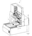
- FIG. 1 shows a perspective view of the front of the measuring machine in a partially sectioned view. Since generic measuring machines are known in principle, in the following, in particular, only the most important components thereof or the elements relevant in connection with the invention will be discussed.
- the measuring machine 1 has a stable machine table 2, on which a clamping device 20 for fixing a workpiece or a pallet is attached.
- a measuring carriage 3 is arranged, which along a first linear axis, here referred to as Y-axis, is movable.
- the measuring carriage 3 is provided with an upper cross member 4, on which a along a second linear axis, here referred to as X-axis, movable cross slide 6 is arranged.
- the cross slide 6 supports a quill 7, which along a third linear axis, here referred to as Z-axis, is movable.
- a measuring head 8 At the lower free end of quill 7 is a measuring head 8, which is provided with a sensor 9.
- the term sensor is here representative of any type of detector, probe, sensor, sensors or the like. As sensor 9, a probe is used in the present example. Instead of a tactile sensor, any other sensors such as an optical sensor or a camera can be used.
- the said movable components 3, 6, 7 together form a mechanism by means of which the sensor 9 in three at least approximately at right angles to each other extending coordinate axes is movable such that thus the surface of a clamped on the machine table 2 by means of the clamping device 20 workpiece (not shown) can be measured.
- the measuring machine 1 further comprises a bearing in the form of a magazine 22.
- the magazine is preferably arranged stationarily on the machine table 2 or in its vicinity.
- This magazine 22 can accommodate a plurality of palletized workpieces, i. of workpieces fixed on pallets.
- the magazine 22 has, for example, three storage levels, wherein in each storage level several pallets equipped with workpieces can be temporarily stored, as will be described in more detail below.
- the magazine 22 is mounted on the machine table 2 and such that workpieces or pallets equipped with workpieces can be transferred externally into the magazine 22 and removed again therefrom.
- the transfer of workpieces or pallets equipped with workpieces from an external location in the magazine 22 is preferably carried out manually. However, it is also conceivable to transfer by means of a handling device.
- a storage location or a magazine several storage locations or magazines may also be provided at different locations.
- a gripper 11 is also arranged, which extends laterally away from the sleeve 7 away.
- This gripper 11 serves to remove workpieces or pallets from the magazine 22 and to pass them to the clamping device 20 or to remove the clamping device 20 and to transfer it into the magazine 22.
- a gripper 11 a so-called finger gripper is used, which comprises two pivotable about one axis fingers, as will be explained in more detail below.
- Such a finger gripper 11 is particularly suitable to Pallets at a predetermined location, for example, at the upper end of a projecting from the pallet down spigot to take. It is understood that, of course, other gripper forms can be used.
- the gripper 11 is preferably operated pneumatically or electrically, wherein the control and power supply via lines or channels on the quill 7 can take place.
- the measuring head 8 and / or the gripper 11 is replaceably attached to the quill 7.
- the sensor 9 can be stored, for example, in a storage space or the magazine 22, while a workpiece is transferred to the clamping device 20 or removed therefrom.
- This has the advantage that the sensor 9 can not be damaged during the movement of the quill 7, namely during the feeding of a workpiece into the clamping device 20 or a removal therefrom, since it is uncoupled from the quill 7.
- an intermediate storage of the sensor 9 in particular depends on the geometric conditions of the measuring machine 1 and its components, for example the clamping device 20.
- the measuring machine 1 is designed such that an intermediate storage of the sensor 9 can be carried out fully automatically, wherein the sensor 9 is preferably fixed by means of a coupling device to the attached to the quill 7 measuring head 8.
- the sensor 9 is preferably fixed by means of a coupling device to the attached to the quill 7 measuring head 8.
- Such a design has the further advantage that the sensor 9 can be replaced by another sensor. As a result, a demand-based exchange and use of different sensors is also made possible.
- the coupling device for clamping the sensor 9 provided with clamping and centering for quick and accurate positioning of the sensor 9 is provided on the measuring head 8.
- a coupling device preferably has feedthroughs for carrying out control lines and / or measuring lines. Possibly. Of course, any necessary energy supply via feedthroughs in the coupling device can take place.
- the gripper 11 can also be fastened interchangeably to the quill 7 by means of a coupling device of the type mentioned. The provision of a coupling device has the advantage that even the gripper 11 can be replaced as needed. Also in this case, the coupling device preferably has feedthroughs for carrying out control lines and / or measuring lines.
- Another advantage of the provision of a coupling device may be that the gripper 11 may possibly be deposited during the measurement of a workpiece, so that collisions and thus damage to the gripper 11 or machine elements can be avoided.
- a possible influence on the measurement accuracy and thus on the measurement result can be avoided since neither the weight of the gripper nor the moments exerted by the gripper on the quill have a detrimental effect on the measurement accuracy. Of course, this makes sense especially when workpieces have to be measured with a very high accuracy.
- the elements of the mechanics namely the measuring slide 3 together with its upper cross member 4, the cross slide 6 and the sleeve 7 are designed so stable that the entire mechanism on the one hand high weights of, for example On the other hand, however, a very accurate measurement of workpieces in the order of approximately 700x700x700 millimeters is still possible.
- the Fig. 2 shows the measuring machine 1 in a view from the back.
- the light barrier arrangement 14 comprises a transmitting unit 15, a receiving unit 16 and two deflecting mirrors 17, 18 arranged therebetween.
- the transmitting unit 15 has a multiplicity of transmitters arranged vertically one above the other, while the receiving unit 16 consists of a plurality of vertically stacked receivers.
- a transmitter for example, light-emitting diodes are used, while as a receiver, for example, photodiodes can be used.
- the transmitting unit 15 emits electromagnetic radiation -Light- in the direction of the first deflecting mirror 17, which deflects the light by 90 ° in the direction of the second deflection mirror 18.
- the second deflecting mirror 18 deflects the light by 90 ° in the direction of the receiving unit 16.
- the light beams are shown by dashed lines 19 hinted.
- the light barrier assembly 14 forms a U-shaped light curtain, which extends over the back of the measuring machine 1, around the measuring carriage 3 and the magazine 22 around. As soon as this light curtain is interrupted, for example by the hand of a person, and the measuring slide is in an area which endangers the person, a dangerous movement of the mechanism, namely the measuring slide 3, the cross slide and the quill, is stopped immediately.
- an additional sensor (not shown) is arranged on the measuring carriage 3 for this purpose.
- the Fig. 3 shows an enlarged section of the measuring machine according Fig. 1 ,
- the stored in two levels in the magazine 22 workpieces 23 can be seen, each workpiece 23 is fixed on a pallet 24.
- no workpieces are stored in this example.
- the measuring head 8 fixed at the lower end of the quill 7 can be seen with the measuring probe 9 arranged at its end.
- the sensor -Measstaster 9- projects beyond the quill 7 in the vertical direction downwards.
- the horizontally extending, the quill 7 at the bottom of laterally superior gripper 11 can be seen, the fingers 12 a pallet 24a engage with a fixed workpiece 23a.
- the gripper 11 engages at the upper end of a projecting from the pallet 24a downwards clamping pin 25.
- the pallet 24a is tightened after transferring into the chuck 21 of the clamping device 20.
- the chuck 21 is provided for this purpose with a pneumatically actuated clamping mechanism, wherein the clamping of a pallet 24 preferably takes place by means of spring force, while the release of the prestressed by means of springs clamping means pneumatically, so that in case of failure or a leak in the pneumatic system, the pallet remains fixed.
- the Fig. 4 shows a further enlarged section of the measuring machine 1.
- the two fingers 12 of the gripper 11 can be seen.
- the gripper 11 is arranged at the lower end of the quill 7 such that it projects beyond it laterally.
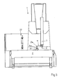
- the Fig. 5 shows the measuring machine 1 in a schematic side view in a sectional view.
- the workpiece carrier 24a pallet is clamped on the machine table 2 by means of the tensioning device 20.
- the tensioning device 20 is provided with positioning means which allow an exact positioning of the pallet at least in the X and Y directions.
- Positioning means are preferably provided which also position the pallet in the Z direction and preferably also about at least one axis of rotation, particularly preferably around the three axes of rotation a, b and c.
- the bearing can be arranged on, above or next to the machine table.
- the design of the storage location or the magazine may be different, for example in the form of a rack, a floor magazine, a turret or a slide. Possibly.
- the mechanism may also have more than three linear axes and / or additionally one or more axes of rotation.
- electronic protective devices such as a camera system or a laser arrangement can be provided instead of a light barrier arrangement. In principle, however, mechanical protective devices are also conceivable.
Landscapes
- Physics & Mathematics (AREA)
- General Physics & Mathematics (AREA)
- Engineering & Computer Science (AREA)
- Mechanical Engineering (AREA)
- Length Measuring Devices With Unspecified Measuring Means (AREA)
- A Measuring Device Byusing Mechanical Method (AREA)
- Machine Tool Sensing Apparatuses (AREA)
- Manipulator (AREA)
Abstract
Die Messmaschine (1) zum Vermessen von Werkstücken (23, 23a) weist einen Maschinentisch (2) und eine Mechanik bestehend aus einem in einer ersten Linearachse bewegbaren Messschlitten, einem an dem Messschlitten angeordneten, in einer zweiten Linearachse bewegbaren Querschlitten und einer an dem Querschlitten angeordneten, in einer dritten Linearachse bewegbaren Pinole (7) auf. An der Pinole (7) ist neben einem Sensor (9) zum Vermessen des Werkstücks auch ein Greifer (11) angeordnet, mittels welchem ein Werkstück (23a) einem Magazin (22) entnommen und an die Spannvorrichtung (20) übergeben bzw. aus der Spannvorrichtung (20) entnommen und an das Magazin (22) übergeben werden kann. Durch diese Ausbildung kann die bestehende Mechanik der Messmaschine (1) genutzt werden, um ein zu vermessendes Werkstück (23, 23a) maschinell an den Messplatz zu überführen und auch wieder daraus zu entnehmen.

Description
Die Erfindung betrifft eine Messmaschine zum Vermessen von Werkstücken. Gattungsgemässe Messmaschinen werden zumeist als Koordinatenmessgeräte bzw. Koordinatenmessmaschinen bezeichnet. Solche Messmaschinen sind mit einem Maschinentisch versehen, auf dem das zu vermessende Werkstück festgespannt oder platziert wird. Zum Vermessen des Werkstücks weist die Messmaschine eine Mechanik auf, mittels welcher ein Sensor in zumindest drei Koordinatenachsen derart verfahrbar ist, dass die Oberfläche des Werkstücks abgetastet bzw. vermessen werden kann. Vorzugsweise ist auf dem Maschinentisch eine Spannvorrichtung angeordnet, mittels welcher das Werkstück oder eine das Werkstück tragende Palette -Werkstückträgerfixiert werden kann. Bevorzugt wird das Werkstück jedoch auf einer Palette befestigt, welche mit Positioniermitteln und einem Spannzapfen o.ä. versehen ist, so dass das Werkstück wiederholt einfach und schnell an der mit korrespondierenden Positioniermitteln versehenen Spannvorrichtung festgespannt werden kann. Eine derartige Spannvorrichtung -Kupplungsvorrichtung- ist beispielsweise aus der
In der
In der
Aufgabe der Erfindung ist es, eine dem eingangs genannten technischen Gebiet zugehörende Messmaschine zu schaffen, welche ein maschinelles Zuführen der zu vermessenden Werkstücke zu der auf dem Maschinentisch der Messmaschine angeordneten Spannvorrichtung bzw. eine Entnahme daraus ermöglicht, ohne dass dazu ein separates, mehrachsiges Handhabungsgerät vorgesehen werden muss.The object of the invention is to provide a measuring machine which belongs to the technical field mentioned above and which enables a machine feed of the workpieces to be measured to the clamping device arranged on the machine table of the measuring machine or a removal therefrom, without the provision of a separate, multi-axis handling device must become.
Die Lösung der Aufgabe ist durch die Merkmale des Anspruchs 1 definiert. Gemäss der Erfindung ist der Messmaschine eine Lagerstelle zur Aufnahme einer Mehrzahl von zu vermessenden Werkstücken zugeordnet oder die Messmaschine weist eine Lagerstelle zur Aufnahme einer Mehrzahl von zu vermessenden Werkstücken auf, wobei die Pinole derart ausgebildet ist, dass zusätzlich zu dem Sensor auch ein Greifer daran fixierbar ist, mittels welchem ein Werkstück von der Lagerstelle an die Spannvorrichtung übergeben bzw. aus der Spannvorrichtung entnommen und an die Lagerstelle übergeben werden kann. Durch die erfindungsgemässe Gestaltung der Messmaschine kann deren bestehende Mechanik genutzt werden, um die zu vermessenden Werkstücke von der Lagerstelle an den Messplatz, namentlich die Spannvorrichtung, zu überführen und wieder daraus zu entnehmen. Dadurch können Kosteneinsparungen erzielt werden, da weder eine Bedienperson noch ein separates Handhabungsgerät zum Zuführen der zu vermessenden Werkstücke an den Messplatz auf dem Maschinentisch bzw. zur Entnahme von dem Messplatz und zur Übergabe an eine Lagerstelle vorgesehen werden muss.The solution of the problem is defined by the features of
Eine derartige Messmaschine kann mittels der bestehenden Mechanik die Werkstücke aus einer Lagerstelle entnehmen, diese an den Messplatz übergeben, die Werkstücke dort vermessen und danach wieder an eine Lagerstelle übergeben. Es versteht sich, dass für die zu vermessenden Werkstücke und die bereits vermessenen Werkstücke ggf. separate Lagerstellen vorgesehen werden können.Such a measuring machine can remove the workpieces from a storage location by means of the existing mechanics, transfer them to the measuring station, measure the workpieces there and then transfer them again to a storage location. It is understood that separate bearings may be provided for the workpieces to be measured and the already measured workpieces.
Sofern die zu vermessenden Werkstücke auf Paletten angeordnet sind, wie dies bei einer bevorzugten Variante vorgesehen ist, ist die Messmaschine vorzugsweise derart gestaltet, dass die Spannvorrichtung zum Festspannen der mit Werkstücken bestückten Paletten ausgebildet ist und der Greifer dem Erfassen der mit Werkstücken bestückten Paletten dient. Die mit Werkstücken bestückten Paletten können mittels der Spannvorrichtung schnell und wiederholbar genau festgespannt werden.If the workpieces to be measured are arranged on pallets, as is provided in a preferred variant, the measuring machine is preferably designed such that the clamping device is designed for clamping the pallets equipped with workpieces and the gripper serves to detect the pallets equipped with workpieces. The pallets equipped with workpieces can be tightened quickly and repeatably by means of the clamping device.
Bei einer bevorzugten Weiterbildung der Messmaschine umfasst die Mechanik einen in einer ersten Linearachse bewegbaren Messschlitten und einen an dem Messschlitten angeordneten, in einer zweiten Linearachse bewegbaren Querschlitten, wobei die Pinole an dem Querschlitten angeordnet und in einer dritten Linearachse bewegbar ist. Eine solche Gestaltung ermöglicht einerseits eine massive Bauweise und andererseits ein Bewegen der Pinole in drei Achsen.In a preferred embodiment of the measuring machine, the mechanism comprises a measuring slide movable in a first linear axis and a transverse slide arranged on the measuring slide and movable in a second linear axis, wherein the sleeve is arranged on the transverse slide and movable in a third linear axis. Such a design allows on the one hand a massive construction and on the other hand, moving the quill in three axes.
Besonders bevorzugt sind der Sensor und/oder der Greifer austauschbar an der Pinole angeordnet. Diese Ausbildung erlaubt ein Entfernen und wieder Ankoppeln des Sensors und/oder des Greifers an der Pinole. Auch ein Zwischenlagern des Sensors und/oder des Greifers wird dadurch ermöglicht.Particularly preferably, the sensor and / or the gripper are arranged interchangeably on the quill. This design allows removal and re-coupling of the sensor and / or the gripper to the quill. An intermediate storage of the sensor and / or the gripper is made possible.
Vorzugsweise wird der Sensor mittels eines Messkopfs an der Pinole angeordnet. Das Vorsehen eines Messkopfs erleichtert die Montage und ggf. den Austausch des Sensors.Preferably, the sensor is arranged by means of a measuring head on the quill. The provision of a measuring head facilitates the assembly and, if necessary, the replacement of the sensor.
Vorzugsweise ist der Sensor mittels einer Kupplungsvorrichtung am Messkopf und/oder der Greifer mittels einer Kupplungsvorrichtung an der Pinole befestigt. Diese Ausbildung erlaubt ein einfaches Entfernen und ein schnelles, positionsdefiniertes Ankoppeln des Sensors und/oder des Greifers an der Pinole. Auch ein Zwischenlagern des Sensors und/oder des Greifers, ggf. in einer Lagerstelle, wird dadurch erleichtert.Preferably, the sensor is attached to the quill by means of a coupling device on the measuring head and / or the gripper by means of a coupling device. This design allows for easy removal and quick, positionally-defined coupling of the sensor and / or the gripper to the quill. An intermediate storage of the sensor and / or the gripper, possibly in a storage location, thereby facilitated.
Vorzugsweise umfasst die Messmaschine als Lagerstelle zumindest ein im Bewegungsbereich des Greifers angeordnetes Magazin zur Aufnahme von Werkstücken und/oder Paletten. In einem solchen Magazin kann ggf. eine grössere Anzahl Werkstücke, Paletten oder mit Werkstücken bestückte Paletten zwischengelagert werden. Dadurch wird eine grosse Autonomie dahingehend ermöglicht, dass das Magazin mit einer grossen Anzahl an zu vermessenden Werkstücken bestückt werden kann, bzw. eine grosse Anzahl an vermessenen Werkstücken darin aufgenommen bzw. zwischengelagert werden kann. Ein solches Magazin kann eignet sich zudem zur Aufnahme bzw. zum Zwischenlagern zumindest eines Messkopfs und/oder zumindest eines Sensors und/oder zumindest eines Greifers. Es versteht sich, dass auch mehrere ggf. unterschiedliche und ggf. auch an verschiedenen Positionen angeordnete Magazine vorgesehen werden können.Preferably, the measuring machine comprises as a bearing at least one arranged in the range of movement of the gripper magazine for receiving workpieces and / or pallets. In such a magazine, if necessary, a larger number of workpieces, pallets or pallets equipped with workpieces be stored. As a result, a great deal of autonomy is made possible in that the magazine can be equipped with a large number of workpieces to be measured, or a large number of measured workpieces can be accommodated therein or temporarily stored. Such a magazine can also be suitable for receiving or for temporarily storing at least one measuring head and / or at least one sensor and / or at least one gripper. It is understood that several possibly different and possibly also arranged at different positions magazines can be provided.
Besonders bevorzugt ist das Magazin bzw. sind die Magazine derart an der Messmaschine angeordnet, dass Werkstücke oder mit Werkstücken bestückte Paletten manuell oder mittels eines Handhabungsgeräts von einer externen Stelle an das jeweilige Magazin übergeben und wieder daraus entnommen werden können. Diese Ausbildung erlaubt, die Messmaschine bzw. das Magazin je nach Bedarf entweder manuell oder ggf. maschinell mit zu vermessenden Werkstücken zu bestücken und die vermessenen Werkstücke wieder daraus zu entnehmen.Particularly preferably, the magazine or the magazines are arranged on the measuring machine such that workpieces or pallets equipped with workpieces can be transferred manually or by means of a handling device from an external location to the respective magazine and removed again therefrom. This training allows to equip the measuring machine or the magazine as needed either manually or, if necessary, mechanically with workpieces to be measured and to remove the measured workpieces again therefrom.
Eine bevorzugte Weiterbildung der Messmaschine sieht vor, dass auf dem Maschinentisch eine mit Positioniermitteln versehene Spannvorrichtung angeordnet ist, mittels welcher eine Palette zumindest in X- und Y-Richtung exakt positionierbar ist. Dadurch wird ein schnelles und genaues Positionieren von Paletten bzw. mit Werkstücken bestückten Paletten auf dem Maschinentisch ermöglicht.A preferred development of the measuring machine provides that a clamping device provided with positioning means is arranged on the machine table, by means of which a pallet can be exactly positioned at least in the X and Y directions. This allows a fast and accurate positioning of pallets or pallets equipped with workpieces on the machine table.
Besonders bevorzugt sind die Positioniermittel derart ausgebildet, dass die Palette zusätzlich auch in Z-Richtung sowie zumindest um eine Drehachse positionierbar ist. Dadurch wird ermöglicht, auch nicht rotationssymmetrisch ausgebildete palettierte Werkstücke räumlich exakt und winkelgenau zu positionieren und fixieren.Particularly preferably, the positioning means are formed such that the pallet is additionally positionable in the Z direction as well as at least about an axis of rotation. This makes it possible to spatially accurate and angularly position and fix even not rotationally symmetrical trained palletized workpieces.
Eine weitere, bevorzugte Weiterbildung sieht vor, dass die Mechanik den Messkopf und/oder den Sensor und/oder den Greifer an eine Lagerstelle übergeben und/oder daraus entnehmen kann. Diese Ausbildung ermöglicht, den Messkopf und/oder den Sensor und/oder den Greifer bedarfsgerecht auszutauschen oder zwischenzulagern. Vorzugsweise ist der Greifer als Fingergreifer, Parallelgreifer, Gabelgreifer, Magnetgreifer oder Vakuumgreifer ausgebildet. Derartige Greifer sind bewährt und in unterschiedlichen Ausführungsformen erhältlich. Sie arbeiten zudem zuverlässig und sind ggf. kostengünstig.A further, preferred development provides that the mechanism can transfer the measuring head and / or the sensor and / or the gripper to a bearing point and / or remove it. This design makes it possible to replace or temporarily store the measuring head and / or the sensor and / or the gripper as needed. Preferably, the gripper is designed as a finger gripper, parallel gripper, fork gripper, magnetic gripper or vacuum gripper. Such grippers are proven and available in different embodiments. They also work reliably and may be inexpensive.
Eine weitere Aufgabe der Erfindung besteht darin, ein Verfahren zum Vermessen eines Werkstücks mittels einer nach einem der vorhergehenden Ansprüche ausgebildeten Messmaschine vorzuschlagen, welches sich in wirtschaftlicher Hinsicht besonders eignet, um das zu vermessende Werkstück in die Spannvorrichtung der Messmaschine zu überführen bzw. daraus zu entnehmen.A further object of the invention is to propose a method for measuring a workpiece by means of a measuring machine designed according to one of the preceding claims, which is particularly suitable from an economic point of view for transferring or removing the workpiece to be measured into the clamping device of the measuring machine ,
Die Lösung der Aufgabe ist durch die Merkmale des Anspruchs 13 definiert. Definitionsgemäss wird das zu vermessende Werkstück oder eine mit dem zu vermessenden Werkstück bestückte Palette mittels des Greifers aus der Lagerstelle entnommen und an die Spannvorrichtung übergeben, wobei danach die Oberfläche des Werkstücks mittels des Sensors erfasst bzw. abgetastet wird und wobei nach dem Ende des Messvorgangs das Werkstück oder die mit dem Werkstück bestückte Palette mittels des Greifers aus der Spannvorrichtung entnommen und an eine Lagerstelle übergeben wird.The solution of the problem is defined by the features of claim 13. By definition, the workpiece to be measured or equipped with the workpiece to be measured pallet is removed by the gripper from the bearing and transferred to the clamping device, after which the surface of the workpiece is detected or scanned by the sensor and wherein after the end of the measuring process Workpiece or stocked with the workpiece pallet is removed by means of the gripper from the jig and transferred to a storage location.
Eine bevorzugte Weiterbildung des Verfahrens sieht vor, dass der Messkopf und/oder der Sensor vor der Entnahme eines Werkstücks aus der Lagerstelle und/oder vor der Entnahme eines Werkstücks aus der Spannvorrichtung von der Pinole abgekoppelt und an eine Lagerstelle ausgelagert wird. Dadurch kann ein Beschädigen des Messkopfs bzw. Sensors während des Bewegens der Pinole zu dem Messplatz bzw. zu der Lagerstelle verhindert werden.A preferred embodiment of the method provides that the measuring head and / or the sensor is decoupled from the sleeve before removal of a workpiece from the bearing and / or prior to removal of a workpiece from the jig and outsourced to a bearing. This can prevent damage to the measuring head or sensor during movement of the quill to the measuring station or to the bearing.
Eine weitere bevorzugte Weiterbildung sieht zudem vor, dass der Greifer vor dem Vermessen eines Werkstücks von der Pinole abgekoppelt und an eine Lagerstelle übergeben wird. Dadurch kann ein allfälliger Einfluss des Greifers auf den Messvorgang bzw. die Messgenauigkeit vermieden werden.A further preferred development also provides that the gripper is decoupled from the quill before measuring a workpiece and transferred to a bearing. As a result, a possible influence of the gripper on the measuring process or the measuring accuracy can be avoided.
Schliesslich sieht ein besonders bevorzugtes Verfahren vor, dass der Greifer vor der Entnahme eines Werkstücks aus der Lagerstelle bzw. vor der Entnahme eines Werkstücks aus der Spannvorrichtung an die Pinole angekoppelt wird. Dies ist notwendig, damit nach einem allfälligen Abkoppeln des Greifers dieser wieder an der Pinole befestigt ist und somit ein Beladen bzw. Entladen der Lagerstelle mittels des Greifers ermöglicht wird.Finally, a particularly preferred method provides that the gripper prior to removal of a workpiece from the bearing or before the removal of a Workpiece is coupled from the clamping device to the quill. This is necessary so that after a possible uncoupling of the gripper this is again attached to the sleeve and thus loading or unloading of the bearing is made possible by means of the gripper.
Nachfolgend wird ein bevorzugtes Ausführungsbeispiel der Erfindung anhand von Zeichnungen näher erläutert. Dabei zeigt:
- Fig. 1
- eine perspektivische Ansicht auf die Vorderseite/Bedienseite der Messmaschine in teilweise geschnittener Darstellung;
- Fig. 2
- eine perspektivische Ansicht auf die Rückseite der Messmaschine;
- Fig. 3
- einen vergrösserten Ausschnitt aus der Darstellung gemäss
Fig. 1 ; - Fig. 4
- ein Detail der Messmaschine in nochmals vergrösserter Darstellung;
- Fig. 5
- die Messmaschine in einer schematischen Seitenansicht in geschnittener Darstellung.
- Fig. 1
- a perspective view of the front / operating side of the measuring machine in a partially sectioned view;
- Fig. 2
- a perspective view of the back of the measuring machine;
- Fig. 3
- an enlarged section of the illustration according to
Fig. 1 ; - Fig. 4
- a detail of the measuring machine in an enlarged view;
- Fig. 5
- the measuring machine in a schematic side view in a sectional view.
Grundsätzlich sind in den Figuren gleiche Teile mit gleichen Bezugszeichen versehen.Basically, the same parts are provided with the same reference numerals in the figures.
Die
Die Messmaschine 1 weist einen stabilen Maschinentisch 2 auf, auf dem eine Spannvorrichtung 20 zum Fixieren eines Werkstücks bzw. einer Palette befestigt ist. Auf dem Maschinentisch 2 ist ein Messschlitten 3 angeordnet, der entlang einer ersten Linearachse, hier als Y-Achse bezeichnet, verfahrbar ist. Der Messschlitten 3 ist mit einem oberen Querträger 4 versehen, an dem ein entlang einer zweiten Linearachse, hier als X-Achse bezeichnet, bewegbarer Querschlitten 6 angeordnet ist. Der Querschlitten 6 lagert eine Pinole 7, die entlang einer dritten Linearachse, hier als Z-Achse bezeichnet, bewegbar ist. Am unteren freien Ende der Pinole 7 ist ein Messkopf 8 angeordnet, der mit einem Sensor 9 versehen ist. Der Begriff Sensor steht hier stellvertretend für jegliche Art von Detektor, Taster, Aufnehmer, Fühler oder dergleichen. Als Sensor 9 kommt im vorliegenden Beispiel ein Messtaster zum Einsatz. Anstelle eines taktilen Sensors können auch beliebig andere Sensoren wie beispielsweise ein optischer Sensor oder eine Kamera zum Einsatz kommen.The measuring
Die genannten beweglichen Bauteile 3, 6, 7 bilden zusammen eine Mechanik, mittels welcher der Sensor 9 in drei zumindest annähernd unter einem rechten Winkel zueinander verlaufenden Koordinatenachsen derart verfahrbar ist, dass damit die Oberfläche eines auf dem Maschinentisch 2 mittels der Spannvorrichtung 20 festgespannten Werkstücks (nicht dargestellt) vermessen werden kann.The said
Die Messmaschine 1 umfasst ferner eine Lagerstelle in Form eines Magazins 22. Das Magazin ist vorzugsweise ortsfest auf dem Maschinentisch 2 oder in dessen Nähe angeordnet. Dieses Magazin 22 kann eine Vielzahl von palettierten Werkstücken, d.h. von auf Paletten fixierten Werkstücken, aufnehmen. Im vorliegenden Beispiel besitzt das Magazin 22 beispielhaft drei Lagerebenen, wobei in jeder Lagerebene mehrere mit Werkstücken bestückte Paletten zwischengelagert werden können, wie nachfolgend noch näher beschrieben wird. Das Magazin 22 ist derart auf dem Maschinentisch 2 befestigt und derart, dass Werkstücke oder mit Werkstücken bestückte Paletten von extern in das Magazin 22 überführt und wieder daraus entnommen werden können. Das Überführen von Werkstücken bzw. mit Werkstücken bestückten Paletten von einer externen Stelle in das Magazin 22 erfolgt vorzugsweise manuell. Denkbar ist jedoch auch ein Überführen mittels eines Handhabungsgeräts. Anstelle einer Lagerstelle bzw. eines Magazins können natürlich auch mehrere Lagerstellen bzw. Magazine ggf. auch an unterschiedlichen Orten vorgesehen werden.The measuring
Am unteren Ende der Pinole 7 ist zudem ein Greifer 11 angeordnet, welcher sich lateral von der Pinole 7 weg erstreckt. Dieser Greifer 11 dient dazu, Werkstücke bzw. Paletten aus dem Magazin 22 zu entnehmen und an die Spannvorrichtung 20 zu übergeben bzw. der Spannvorrichtung 20 zu entnehmen und in das Magazin 22 zu überführen. Im vorliegenden Beispiel kommt als Greifer 11 ein sogenannter Fingergreifer zum Einsatz, welcher zwei um jeweils eine Achse schwenkbare Finger umfasst, wie nachfolgend noch näher erläutert wird. Ein solcher Fingergreifer 11 eignet sich insbesondere, um Paletten an einer vorgegebenen Stelle, beispielsweise am oberen Ende eines von der Palette nach unten abstehenden Spannzapfens, zu ergreifen. Es versteht sich, dass natürlich auch andere Greiferformen eingesetzt werden können.At the lower end of the
Der Greifer 11 wird vorzugsweise pneumatisch oder elektrisch betätigt, wobei die Ansteuerung und Energiezufuhr über Leitungen oder Kanäle an der Pinole 7 erfolgen kann. Vorzugsweise ist der Messkopf 8 und/oder der Greifer 11 austauschbar an der Pinole 7 befestigt. Die sich daraus ergebenden Vorteile werden nachfolgend noch näher erläutert. Alternativ kann natürlich auch ein passiver Greifer, beispielsweise ein Gabelgreifer, eingesetzt werden.The
Sofern der Sensor 9 austauschbar an dem Messkopf 8 befestigt ist, kann der Sensor 9 beispielsweise in einem Abstellplatz oder dem Magazin 22 zwischengelagert werden, während ein Werkstück in die Spannvorrichtung 20 überführt oder daraus entnommen wird. Dies hat den Vorteil, dass der Sensor 9 während des Bewegens der Pinole 7, namentlich während des Zuführens eines Werkstücks in die Spannvorrichtung 20 bzw. einer Entnahme daraus, nicht beschädigt werden kann, da er von der Pinole 7 abgekoppelt ist. Es versteht sich, dass ein Zwischenlagern des Sensors 9 insbesondere von den geometrischen Gegebenheiten der Messmaschine 1 und ihrer Komponenten, beispielsweise der Spannvorrichtung 20, abhängt. Vorzugsweise ist die Messmaschine 1 derart gestaltet, dass ein Zwischenlagern des Sensors 9 vollautomatisch erfolgen kann, wobei der Sensor 9 dazu vorzugsweise mittels einer Kupplungsvorrichtung an dem an der Pinole 7 befestigten Messkopf 8 fixiert ist. Eine solche Gestaltung hat den weiteren Vorteil, dass der Sensor 9 durch einen anderen Sensor ausgetauscht werden kann. Dadurch wird zusätzlich ein bedarfsgerechter Austausch und Einsatz von unterschiedlichen Sensoren ermöglicht.If the
Vorzugsweise ist die zum Befestigen des Sensors 9 allenfalls vorgesehene Kupplungsvorrichtung mit Spann- und Zentrierelementen zum schnellen und genauen Positionieren des Sensors 9 an dem Messkopf 8 versehen. Des Weiteren weist eine solche Kupplungsvorrichtung vorzugsweise Durchführungen zum Durchführen von Steuerleitungen und/oder Messleitungen auf. Ggf. kann natürlich auch eine allfällig notwendige Energiezufuhr über Durchführungen in der Kupplungsvorrichtung erfolgen. Andererseits kann auch der Greifer 11 mittels einer Kupplungsvorrichtung der genannten Art austauschbar an der Pinole 7 befestigt werden. Das Vorsehen einer Kupplungsvorrichtung bietet den Vorteil, dass auch der Greifer 11 bedarfsgerecht ausgetauscht werden kann. Auch in diesem Fall weist die Kupplungsvorrichtung vorzugsweise Durchführungen zum Durchführen von Steuerleitungen und/oder Messleitungen auf. Ein weiterer Vorteil des Vorsehens einer Kupplungsvorrichtung kann darin bestehen, dass der Greifer 11 während des Vermessens eines Werkstücks ggf. abgelegt werden kann, so dass Kollisionen und damit Beschädigungen des Greifers 11 bzw. von Maschinenelementen vermieden werden können. Zudem kann ein allfälliger Einfluss auf die Messgenauigkeit und damit auf das Messergebnis vermieden werden, da weder das Gewicht des Greifers noch die durch den Greifer auf die Pinole ausgeübten Momente einen nachteiligen Einfluss auf die Messgenauigkeit haben. Dies macht natürlich insbesondere dann Sinn, wenn Werkstücke mit einer sehr hohen Genauigkeit vermessen werden müssen.Preferably, the coupling device for clamping the
Neben dem Maschinentisch 2, welcher üblicherweise aus einer massiven Steinplatte besteht, sind auch die Elemente der Mechanik, namentlich der Messschlitten 3 mitsamt seinem oberen Querträger 4, der Querschlitten 6 sowie die Pinole 7 derart stabil ausgebildet, dass die gesamte Mechanik einerseits hohe Gewichte von beispielsweise bis zu 50 Kilogramm aufnehmen kann, andererseits jedoch trotzdem ein sehr genaues Vermessen von Werkstücken in der Grössenordnung von ca. 700x700x700 Millimetern ermöglicht wird.In addition to the machine table 2, which usually consists of a solid stone slab, the elements of the mechanics, namely the measuring
Die
Die
Die
Die
Wenn im vorliegenden Dokument jeweils von Werkstück gesprochen wird, so ist darunter nicht nur ein Werkstück im herkömmlichen Sinn zu verstehen, sondern der Begriff Werkstück steht stellvertretend auch für Werkzeuge wie beispielsweise Elektroden oder Ähnlichem.Whenever reference is made in this document to the workpiece, this does not only mean a workpiece in the conventional sense, but the term workpiece is also representative of tools such as electrodes or the like.
Die Vorteile einer erfindungsgemäss gestalteten Messmaschine lassen sich wie folgt zusammenfassen:
- Kostengünstige Lösung zum automatischen Zuführen von zu vermessenden Werkstücken an den Messplatz und zur automatischen Entnahme davon;
- Einfach realisierbar, da die Lösung auf der bestehenden Mechanik der Messmaschine aufbaut;
- Stand alone Lösung;
- Bestehende Messmaschinen sind ggf. nachrüstbar;
- Platzsparend, da kein zusätzlicher Beladeroboter notwendig ist;
- Je nach Grösse des Magazins/Lagerstelle wird eine Autonomie von mehreren Stunden ermöglicht;
- Betriebssichere Ausführung bei integrierter Schutzeinrichtung wie beispielsweise einer Lichtschrankenanordnung.
- Cost-effective solution for automatically feeding workpieces to be measured to the measuring station and for automatically removing them;
- Easy to implement as the solution builds on the existing mechanics of the measuring machine;
- Stand alone solution;
- Existing measuring machines may be retrofitted;
- Space saving, since no additional loading robot is necessary;
- Depending on the size of the magazine / storage location, an autonomy of several hours is possible;
- Operationally safe design with integrated protective device such as a photoelectric barrier arrangement.
Es versteht sich, dass das vorgängig anhand der Zeichnungen erläuterte Ausführungsbeispiel keinesfalls als abschliessend zu betrachten ist, sondern dass im Rahmen des in den Patentansprüchen definierten Schutzumfangs durchaus von dem erläuterten Ausführungsbeispiel abweichende Gestaltungen möglich sind. So sind abweichende Gestaltungen des Greifers beispielsweise in der Form eines Fingergreifers, eines Parallelgreifers, oder eines passiven formschlüssigen Greifers wie beispielsweise eines Gabelgreifers möglich. Aber auch magnetische oder Vakuumgreifer sind ohne weiteres denkbar. Auch das Vorsehen von mehr als einem Greifer und/oder mehr als einem Sensor ist durchaus denkbar. Als Alternative zu einem taktilen Sensor kann auch ein berührungsloser, beispielsweise ein optischer Sensor eingesetzt werden. Auch eine Variation bezüglich der Anzahl und/oder Anordnung der Lagerstelle bzw. des Magazins oder der Magazine ist ohne weiteres möglich. So kann die Lagerstelle beispielsweise auf, über oder neben dem Maschinentisch angeordnet werden. Auch die Ausbildung der Lagerstelle bzw. des Magazins kann unterschiedlich sein, beispielsweise in der Form eins Racks, eines Etagenmagazins, eines Drehturms oder einer Rutsche. Ggf. kann die Mechanik auch mehr als drei Linearachsen und/oder zusätzlich eine oder mehrere Drehachsen aufweisen. Grundsätzlich wäre es auch möglich, das Magazin austauschbar anzuordnen, so dass die zu vermessenden Werkstücke nicht von einer externen Stelle in das Magazin überführt würden, sondern dass jeweils das gesamte Magazin ausgetauscht würde. Dabei würde das mit den bereits vermessenen Werkstücken bestückte Magazin gegen ein anderes Magazin ausgetauscht, welches mit den noch zu vermessenden Werkstücken bestückt ist. Schliesslich können anstelle einer Lichtschrankenanordnung auch alternative, vorzugsweise elektronische Schutzeinrichtungen wie beispielsweise ein Kamerasystem oder eine Laseranordnung vorgesehen werden. Grundsätzlich sind aber auch mechanische Schutzeinrichtungen denkbar.It is understood that the embodiment explained above with reference to the drawings is by no means to be considered as conclusive, but that within the scope of the scope defined in the claims quite different from the illustrated embodiment deviations are possible. Thus, different configurations of the gripper, for example in the form of a finger gripper, a parallel gripper, or a passive positive gripper such as a fork gripper are possible. But magnetic or vacuum gripper are also conceivable. The provision of more than one gripper and / or more than one sensor is quite conceivable. As an alternative to a tactile sensor, a non-contact, for example, an optical sensor can be used. Also, a variation in the number and / or arrangement of the bearing or the magazine or magazines is readily possible. For example, the bearing can be arranged on, above or next to the machine table. The design of the storage location or the magazine may be different, for example in the form of a rack, a floor magazine, a turret or a slide. Possibly. The mechanism may also have more than three linear axes and / or additionally one or more axes of rotation. In principle, it would also be possible to arrange the magazine interchangeably, so that the workpieces to be measured would not be transferred from an external location into the magazine, but that in each case the entire magazine would be replaced. In this case, the magazine stocked with the already measured workpieces would be exchanged for another magazine which is equipped with the workpieces still to be measured. Finally, alternative, preferably electronic protective devices such as a camera system or a laser arrangement can be provided instead of a light barrier arrangement. In principle, however, mechanical protective devices are also conceivable.
Claims (16)
Applications Claiming Priority (1)
| Application Number | Priority Date | Filing Date | Title |
|---|---|---|---|
| CH00086/15A CH710648A1 (en) | 2015-01-23 | 2015-01-23 | Measuring machine for measuring workpieces. |
Publications (2)
| Publication Number | Publication Date |
|---|---|
| EP3048413A1 true EP3048413A1 (en) | 2016-07-27 |
| EP3048413B1 EP3048413B1 (en) | 2018-03-07 |
Family
ID=55079929
Family Applications (1)
| Application Number | Title | Priority Date | Filing Date |
|---|---|---|---|
| EP15003186.2A Active EP3048413B1 (en) | 2015-01-23 | 2015-11-06 | Measuring machine for measuring workpieces |
Country Status (6)
| Country | Link |
|---|---|
| US (1) | US9863751B2 (en) |
| EP (1) | EP3048413B1 (en) |
| JP (1) | JP6283701B2 (en) |
| CN (1) | CN105823447B (en) |
| CH (1) | CH710648A1 (en) |
| TW (1) | TWI659190B (en) |
Cited By (2)
| Publication number | Priority date | Publication date | Assignee | Title |
|---|---|---|---|---|
| DE102019008003A1 (en) | 2019-11-18 | 2020-07-09 | Daimler Ag | Process for machining and testing a cylinder head |
| DE102017126836B4 (en) | 2017-11-15 | 2024-01-18 | POS GmbH & Co. KG | processing machine |
Families Citing this family (9)
| Publication number | Priority date | Publication date | Assignee | Title |
|---|---|---|---|---|
| JP6379197B2 (en) * | 2013-08-01 | 2018-08-22 | ハイジトロン, インク.Hysitron, Inc. | Apparatus for modifying an assembly and method therefor |
| CH710648A1 (en) * | 2015-01-23 | 2016-07-29 | Erowa Ag | Measuring machine for measuring workpieces. |
| US10585419B1 (en) | 2016-04-27 | 2020-03-10 | Beneficial Machine Tools Llc | Methods and devices for performing in-situ inspections during a computer assisted setup of a machine tool table |
| US10416647B1 (en) | 2016-04-27 | 2019-09-17 | Beneficial Machine Tools Llc | Apparatus for determining axes for the computer assisted setup of a machine tool table |
| US9903699B2 (en) * | 2016-04-27 | 2018-02-27 | Beneficial Photonics, Inc. | Apparatus for the computer assisted setup of a machine tool table |
| JP7360790B2 (en) * | 2018-10-23 | 2023-10-13 | 株式会社ミツトヨ | CMM |
| GB201908127D0 (en) * | 2019-06-07 | 2019-07-24 | Renishaw Plc | Manufacturing method and apparatus |
| CN110271037A (en) * | 2019-07-18 | 2019-09-24 | 华域汽车车身零件(沈阳)有限公司 | A kind of intelligent detecting method for spot welding robot's production line |
| CN114535714A (en) * | 2022-04-25 | 2022-05-27 | 深圳市国天电子股份有限公司 | High-precision machining equipment and method for vehicle-mounted millimeter radar cover |
Citations (11)
| Publication number | Priority date | Publication date | Assignee | Title |
|---|---|---|---|---|
| US4305130A (en) * | 1979-05-29 | 1981-12-08 | University Of Rhode Island | Apparatus and method to enable a robot with vision to acquire, orient and transport workpieces |
| EP0111092A1 (en) | 1982-10-18 | 1984-06-20 | Erowa AG | Coupling device |
| DE3417741A1 (en) | 1984-05-12 | 1985-11-14 | Mauser-Werke Oberndorf Gmbh, 7238 Oberndorf | Device for measuring workpieces |
| US4631834A (en) * | 1984-04-20 | 1986-12-30 | Mitutuoyo Mfg. Co., Ltd. | Coordinate measuring instrument |
| US5028901A (en) * | 1989-07-07 | 1991-07-02 | Carl-Zeiss Stiftung | Magazine for coordinate measuring apparatus |
| EP0568798A1 (en) * | 1992-04-10 | 1993-11-10 | EMAG-MASCHINEN VERTRIEBS- und SERVICE GmbH | Machining center consisting of assembled modules |
| DE4227817A1 (en) | 1992-08-21 | 1994-02-24 | Eos Electro Optical Syst | Coordinate measuring machine for surface measurement - has holder of three=dimensional positioning system for alternately mounting probe or Moire measurement head |
| US5918378A (en) * | 1996-03-16 | 1999-07-06 | Renishaw Plc | Inspection system for coordinate positioning machine |
| US5945009A (en) * | 1995-05-12 | 1999-08-31 | Vollmer Werke Maschinenfabrik Gmbh | Apparatus for processing workpieces by spark erosion |
| US7177459B1 (en) * | 1999-04-08 | 2007-02-13 | Fanuc Ltd | Robot system having image processing function |
| US20100250178A1 (en) * | 2009-03-25 | 2010-09-30 | Mitutoyo Corporation | Corrected ball diameter calculating method and form measuring instrument |
Family Cites Families (14)
| Publication number | Priority date | Publication date | Assignee | Title |
|---|---|---|---|---|
| JPS60224008A (en) * | 1984-04-20 | 1985-11-08 | Mitsutoyo Mfg Co Ltd | Device for automatically attaching and detaching probe of three dimensional measuring machine |
| DE69217548T2 (en) * | 1991-11-09 | 1997-06-05 | Renishaw Metrology Ltd | MEASURING PROBE |
| JP3366052B2 (en) * | 1993-04-07 | 2003-01-14 | 宗弘 先生 | Comparative length measuring device |
| CN1145840A (en) * | 1995-09-14 | 1997-03-26 | 邵文远 | Integrated machining center |
| DE19958306C2 (en) * | 1999-12-03 | 2002-03-14 | Zeiss Carl | Coordinate measuring |
| JP2003106816A (en) * | 2001-10-01 | 2003-04-09 | Dainippon Printing Co Ltd | Film thickness-measuring method and apparatus |
| US7694583B2 (en) * | 2005-05-05 | 2010-04-13 | Control Gaging, Inc. | Gripper gage assembly |
| CN1912627B (en) * | 2006-08-23 | 2011-05-11 | 陕西北美基因股份有限公司 | Blood treatment working station based on micronano magnetic particle and its control method |
| DE102007004423A1 (en) * | 2007-01-23 | 2008-07-31 | Carl Zeiss Industrielle Messtechnik Gmbh | Control of an operation of a coordinate measuring machine |
| DE102007013633A1 (en) * | 2007-03-19 | 2008-09-25 | Carl Zeiss Industrielle Messtechnik Gmbh | Measurement object and holder e.g. magazine, identifying method for coordinate measuring device, involves producing scanning signal, which corresponds to shape, orientation of identification body of holder, or position with respect to body |
| DE102009060784A1 (en) * | 2009-12-22 | 2011-06-30 | Carl Zeiss 3D Automation GmbH, 73447 | Stylus and probe for a coordinate measuring machine |
| EP2847539B1 (en) * | 2012-05-07 | 2020-02-12 | Carl Zeiss Industrielle Messtechnik GmbH | Replaceable illumination module for a co-ordinate measuring machine |
| DE102013105753B3 (en) * | 2013-06-04 | 2014-10-02 | Carl Zeiss Industrielle Messtechnik Gmbh | Method for automatically picking up a sensor head and coordinate measuring machine |
| CH710648A1 (en) * | 2015-01-23 | 2016-07-29 | Erowa Ag | Measuring machine for measuring workpieces. |
-
2015
- 2015-01-23 CH CH00086/15A patent/CH710648A1/en not_active Application Discontinuation
- 2015-11-06 EP EP15003186.2A patent/EP3048413B1/en active Active
- 2015-11-09 TW TW104136803A patent/TWI659190B/en active
- 2015-12-10 US US14/965,471 patent/US9863751B2/en active Active
-
2016
- 2016-01-22 CN CN201610042536.9A patent/CN105823447B/en active Active
- 2016-01-22 JP JP2016010876A patent/JP6283701B2/en active Active
Patent Citations (11)
| Publication number | Priority date | Publication date | Assignee | Title |
|---|---|---|---|---|
| US4305130A (en) * | 1979-05-29 | 1981-12-08 | University Of Rhode Island | Apparatus and method to enable a robot with vision to acquire, orient and transport workpieces |
| EP0111092A1 (en) | 1982-10-18 | 1984-06-20 | Erowa AG | Coupling device |
| US4631834A (en) * | 1984-04-20 | 1986-12-30 | Mitutuoyo Mfg. Co., Ltd. | Coordinate measuring instrument |
| DE3417741A1 (en) | 1984-05-12 | 1985-11-14 | Mauser-Werke Oberndorf Gmbh, 7238 Oberndorf | Device for measuring workpieces |
| US5028901A (en) * | 1989-07-07 | 1991-07-02 | Carl-Zeiss Stiftung | Magazine for coordinate measuring apparatus |
| EP0568798A1 (en) * | 1992-04-10 | 1993-11-10 | EMAG-MASCHINEN VERTRIEBS- und SERVICE GmbH | Machining center consisting of assembled modules |
| DE4227817A1 (en) | 1992-08-21 | 1994-02-24 | Eos Electro Optical Syst | Coordinate measuring machine for surface measurement - has holder of three=dimensional positioning system for alternately mounting probe or Moire measurement head |
| US5945009A (en) * | 1995-05-12 | 1999-08-31 | Vollmer Werke Maschinenfabrik Gmbh | Apparatus for processing workpieces by spark erosion |
| US5918378A (en) * | 1996-03-16 | 1999-07-06 | Renishaw Plc | Inspection system for coordinate positioning machine |
| US7177459B1 (en) * | 1999-04-08 | 2007-02-13 | Fanuc Ltd | Robot system having image processing function |
| US20100250178A1 (en) * | 2009-03-25 | 2010-09-30 | Mitutoyo Corporation | Corrected ball diameter calculating method and form measuring instrument |
Cited By (2)
| Publication number | Priority date | Publication date | Assignee | Title |
|---|---|---|---|---|
| DE102017126836B4 (en) | 2017-11-15 | 2024-01-18 | POS GmbH & Co. KG | processing machine |
| DE102019008003A1 (en) | 2019-11-18 | 2020-07-09 | Daimler Ag | Process for machining and testing a cylinder head |
Also Published As
| Publication number | Publication date |
|---|---|
| US20160216098A1 (en) | 2016-07-28 |
| CN105823447A (en) | 2016-08-03 |
| CN105823447B (en) | 2019-10-11 |
| CH710648A1 (en) | 2016-07-29 |
| US9863751B2 (en) | 2018-01-09 |
| JP6283701B2 (en) | 2018-02-21 |
| TW201632831A (en) | 2016-09-16 |
| TWI659190B (en) | 2019-05-11 |
| JP2016176923A (en) | 2016-10-06 |
| EP3048413B1 (en) | 2018-03-07 |
Similar Documents
| Publication | Publication Date | Title |
|---|---|---|
| EP3048413B1 (en) | Measuring machine for measuring workpieces | |
| EP0819627B1 (en) | Lifting apparatus for handling objects,and device for loading and unloading pallets | |
| DE102017104246B4 (en) | Autonomous production line | |
| EP0616874B1 (en) | Robot arm for a portal robot | |
| DE102017110035A1 (en) | machine tool | |
| EP3268165B1 (en) | Clamping means system capable of automation | |
| WO2001000370A1 (en) | Method and device for calibrating robot measuring stations, manipulators and associated optical measuring devices | |
| EP2655013B1 (en) | Device for blocking eyeglass lenses | |
| EP3257623A1 (en) | Handling device for use on a machine tool | |
| EP3533572B1 (en) | Plate separating installation and method for operating same | |
| DE102008055795A1 (en) | Grinding machine, particularly vertical grinding machine, has measuring device and workpiece spindle unit with clamping device for clamping workpiece, where fist grinding unit is provided for grinding workpiece | |
| AT509260A1 (en) | MOVING AND POSITIONING DEVICE | |
| DE19756278B4 (en) | Machine system for processing cubic workpieces in particular | |
| DE4111545A1 (en) | Rotary indexing machine - has exchangeable workpiece holding fixtures on indexing table | |
| DE4033036A1 (en) | Machine tool with tool store rear - has rotatable arms and carriages to transfer tools from spindle to tool rack | |
| EP3023193A1 (en) | Workpiece supply device | |
| DE10361920B4 (en) | Apparatus and method for controlling tools | |
| DE102016123770A1 (en) | System and method for handling mass-flow moving articles such as beverage containers or the like | |
| EP3446830B1 (en) | Device and method for measuring a machine tool | |
| EP3292951A1 (en) | Method for indirect handling of at least one workpiece tensioned on a tensioning pallet and device for same | |
| DE102018104199B4 (en) | Machine tool with work area, setup station and robot arm and method for their operation | |
| DE102017126836B4 (en) | processing machine | |
| DE4316338C2 (en) | Holding and transport device for particularly flat workpieces | |
| EP3184958A1 (en) | Sensor arrangement for workpiece identification and/or workpiece placement detection of a plurality of workpieces within a transport holder | |
| EP4275838A1 (en) | Pick and place device, machine tool and method for feeding or removing tools |
Legal Events
| Date | Code | Title | Description |
|---|---|---|---|
| PUAI | Public reference made under article 153(3) epc to a published international application that has entered the european phase |
Free format text: ORIGINAL CODE: 0009012 |
|
| AK | Designated contracting states |
Kind code of ref document: A1 Designated state(s): AL AT BE BG CH CY CZ DE DK EE ES FI FR GB GR HR HU IE IS IT LI LT LU LV MC MK MT NL NO PL PT RO RS SE SI SK SM TR |
|
| AX | Request for extension of the european patent |
Extension state: BA ME |
|
| 17P | Request for examination filed |
Effective date: 20161104 |
|
| GRAP | Despatch of communication of intention to grant a patent |
Free format text: ORIGINAL CODE: EPIDOSNIGR1 |
|
| INTG | Intention to grant announced |
Effective date: 20171109 |
|
| GRAS | Grant fee paid |
Free format text: ORIGINAL CODE: EPIDOSNIGR3 |
|
| GRAA | (expected) grant |
Free format text: ORIGINAL CODE: 0009210 |
|
| AK | Designated contracting states |
Kind code of ref document: B1 Designated state(s): AL AT BE BG CH CY CZ DE DK EE ES FI FR GB GR HR HU IE IS IT LI LT LU LV MC MK MT NL NO PL PT RO RS SE SI SK SM TR |
|
| REG | Reference to a national code |
Ref country code: GB Ref legal event code: FG4D Free format text: NOT ENGLISH |
|
| REG | Reference to a national code |
Ref country code: CH Ref legal event code: EP Ref country code: CH Ref legal event code: NV Representative=s name: ROTTMANN, ZIMMERMANN + PARTNER AG, CH Ref country code: AT Ref legal event code: REF Ref document number: 977048 Country of ref document: AT Kind code of ref document: T Effective date: 20180315 |
|
| REG | Reference to a national code |
Ref country code: IE Ref legal event code: FG4D Free format text: LANGUAGE OF EP DOCUMENT: GERMAN |
|
| REG | Reference to a national code |
Ref country code: DE Ref legal event code: R096 Ref document number: 502015003271 Country of ref document: DE |
|
| REG | Reference to a national code |
Ref country code: SE Ref legal event code: TRGR |
|
| REG | Reference to a national code |
Ref country code: NL Ref legal event code: MP Effective date: 20180307 |
|
| REG | Reference to a national code |
Ref country code: LT Ref legal event code: MG4D |
|
| PG25 | Lapsed in a contracting state [announced via postgrant information from national office to epo] |
Ref country code: LT Free format text: LAPSE BECAUSE OF FAILURE TO SUBMIT A TRANSLATION OF THE DESCRIPTION OR TO PAY THE FEE WITHIN THE PRESCRIBED TIME-LIMIT Effective date: 20180307 Ref country code: ES Free format text: LAPSE BECAUSE OF FAILURE TO SUBMIT A TRANSLATION OF THE DESCRIPTION OR TO PAY THE FEE WITHIN THE PRESCRIBED TIME-LIMIT Effective date: 20180307 Ref country code: CY Free format text: LAPSE BECAUSE OF FAILURE TO SUBMIT A TRANSLATION OF THE DESCRIPTION OR TO PAY THE FEE WITHIN THE PRESCRIBED TIME-LIMIT Effective date: 20180307 Ref country code: FI Free format text: LAPSE BECAUSE OF FAILURE TO SUBMIT A TRANSLATION OF THE DESCRIPTION OR TO PAY THE FEE WITHIN THE PRESCRIBED TIME-LIMIT Effective date: 20180307 Ref country code: HR Free format text: LAPSE BECAUSE OF FAILURE TO SUBMIT A TRANSLATION OF THE DESCRIPTION OR TO PAY THE FEE WITHIN THE PRESCRIBED TIME-LIMIT Effective date: 20180307 Ref country code: NO Free format text: LAPSE BECAUSE OF FAILURE TO SUBMIT A TRANSLATION OF THE DESCRIPTION OR TO PAY THE FEE WITHIN THE PRESCRIBED TIME-LIMIT Effective date: 20180607 |
|
| PG25 | Lapsed in a contracting state [announced via postgrant information from national office to epo] |
Ref country code: RS Free format text: LAPSE BECAUSE OF FAILURE TO SUBMIT A TRANSLATION OF THE DESCRIPTION OR TO PAY THE FEE WITHIN THE PRESCRIBED TIME-LIMIT Effective date: 20180307 Ref country code: BG Free format text: LAPSE BECAUSE OF FAILURE TO SUBMIT A TRANSLATION OF THE DESCRIPTION OR TO PAY THE FEE WITHIN THE PRESCRIBED TIME-LIMIT Effective date: 20180607 Ref country code: LV Free format text: LAPSE BECAUSE OF FAILURE TO SUBMIT A TRANSLATION OF THE DESCRIPTION OR TO PAY THE FEE WITHIN THE PRESCRIBED TIME-LIMIT Effective date: 20180307 Ref country code: GR Free format text: LAPSE BECAUSE OF FAILURE TO SUBMIT A TRANSLATION OF THE DESCRIPTION OR TO PAY THE FEE WITHIN THE PRESCRIBED TIME-LIMIT Effective date: 20180608 |
|
| PG25 | Lapsed in a contracting state [announced via postgrant information from national office to epo] |
Ref country code: MT Free format text: LAPSE BECAUSE OF FAILURE TO SUBMIT A TRANSLATION OF THE DESCRIPTION OR TO PAY THE FEE WITHIN THE PRESCRIBED TIME-LIMIT Effective date: 20180307 |
|
| PG25 | Lapsed in a contracting state [announced via postgrant information from national office to epo] |
Ref country code: AL Free format text: LAPSE BECAUSE OF FAILURE TO SUBMIT A TRANSLATION OF THE DESCRIPTION OR TO PAY THE FEE WITHIN THE PRESCRIBED TIME-LIMIT Effective date: 20180307 Ref country code: RO Free format text: LAPSE BECAUSE OF FAILURE TO SUBMIT A TRANSLATION OF THE DESCRIPTION OR TO PAY THE FEE WITHIN THE PRESCRIBED TIME-LIMIT Effective date: 20180307 Ref country code: NL Free format text: LAPSE BECAUSE OF FAILURE TO SUBMIT A TRANSLATION OF THE DESCRIPTION OR TO PAY THE FEE WITHIN THE PRESCRIBED TIME-LIMIT Effective date: 20180307 Ref country code: EE Free format text: LAPSE BECAUSE OF FAILURE TO SUBMIT A TRANSLATION OF THE DESCRIPTION OR TO PAY THE FEE WITHIN THE PRESCRIBED TIME-LIMIT Effective date: 20180307 Ref country code: PL Free format text: LAPSE BECAUSE OF FAILURE TO SUBMIT A TRANSLATION OF THE DESCRIPTION OR TO PAY THE FEE WITHIN THE PRESCRIBED TIME-LIMIT Effective date: 20180307 |
|
| PG25 | Lapsed in a contracting state [announced via postgrant information from national office to epo] |
Ref country code: SM Free format text: LAPSE BECAUSE OF FAILURE TO SUBMIT A TRANSLATION OF THE DESCRIPTION OR TO PAY THE FEE WITHIN THE PRESCRIBED TIME-LIMIT Effective date: 20180307 Ref country code: SK Free format text: LAPSE BECAUSE OF FAILURE TO SUBMIT A TRANSLATION OF THE DESCRIPTION OR TO PAY THE FEE WITHIN THE PRESCRIBED TIME-LIMIT Effective date: 20180307 Ref country code: CZ Free format text: LAPSE BECAUSE OF FAILURE TO SUBMIT A TRANSLATION OF THE DESCRIPTION OR TO PAY THE FEE WITHIN THE PRESCRIBED TIME-LIMIT Effective date: 20180307 |
|
| REG | Reference to a national code |
Ref country code: DE Ref legal event code: R097 Ref document number: 502015003271 Country of ref document: DE |
|
| PG25 | Lapsed in a contracting state [announced via postgrant information from national office to epo] |
Ref country code: PT Free format text: LAPSE BECAUSE OF FAILURE TO SUBMIT A TRANSLATION OF THE DESCRIPTION OR TO PAY THE FEE WITHIN THE PRESCRIBED TIME-LIMIT Effective date: 20180709 |
|
| PLBE | No opposition filed within time limit |
Free format text: ORIGINAL CODE: 0009261 |
|
| STAA | Information on the status of an ep patent application or granted ep patent |
Free format text: STATUS: NO OPPOSITION FILED WITHIN TIME LIMIT |
|
| PG25 | Lapsed in a contracting state [announced via postgrant information from national office to epo] |
Ref country code: DK Free format text: LAPSE BECAUSE OF FAILURE TO SUBMIT A TRANSLATION OF THE DESCRIPTION OR TO PAY THE FEE WITHIN THE PRESCRIBED TIME-LIMIT Effective date: 20180307 |
|
| 26N | No opposition filed |
Effective date: 20181210 |
|
| PG25 | Lapsed in a contracting state [announced via postgrant information from national office to epo] |
Ref country code: SI Free format text: LAPSE BECAUSE OF FAILURE TO SUBMIT A TRANSLATION OF THE DESCRIPTION OR TO PAY THE FEE WITHIN THE PRESCRIBED TIME-LIMIT Effective date: 20180307 |
|
| PG25 | Lapsed in a contracting state [announced via postgrant information from national office to epo] |
Ref country code: MC Free format text: LAPSE BECAUSE OF FAILURE TO SUBMIT A TRANSLATION OF THE DESCRIPTION OR TO PAY THE FEE WITHIN THE PRESCRIBED TIME-LIMIT Effective date: 20180307 Ref country code: LU Free format text: LAPSE BECAUSE OF NON-PAYMENT OF DUE FEES Effective date: 20181106 |
|
| REG | Reference to a national code |
Ref country code: BE Ref legal event code: MM Effective date: 20181130 |
|
| REG | Reference to a national code |
Ref country code: IE Ref legal event code: MM4A |
|
| PG25 | Lapsed in a contracting state [announced via postgrant information from national office to epo] |
Ref country code: IE Free format text: LAPSE BECAUSE OF NON-PAYMENT OF DUE FEES Effective date: 20181106 |
|
| PG25 | Lapsed in a contracting state [announced via postgrant information from national office to epo] |
Ref country code: BE Free format text: LAPSE BECAUSE OF NON-PAYMENT OF DUE FEES Effective date: 20181130 |
|
| PG25 | Lapsed in a contracting state [announced via postgrant information from national office to epo] |
Ref country code: TR Free format text: LAPSE BECAUSE OF FAILURE TO SUBMIT A TRANSLATION OF THE DESCRIPTION OR TO PAY THE FEE WITHIN THE PRESCRIBED TIME-LIMIT Effective date: 20180307 |
|
| PG25 | Lapsed in a contracting state [announced via postgrant information from national office to epo] |
Ref country code: MK Free format text: LAPSE BECAUSE OF NON-PAYMENT OF DUE FEES Effective date: 20180307 Ref country code: HU Free format text: LAPSE BECAUSE OF FAILURE TO SUBMIT A TRANSLATION OF THE DESCRIPTION OR TO PAY THE FEE WITHIN THE PRESCRIBED TIME-LIMIT; INVALID AB INITIO Effective date: 20151106 |
|
| PG25 | Lapsed in a contracting state [announced via postgrant information from national office to epo] |
Ref country code: IS Free format text: LAPSE BECAUSE OF FAILURE TO SUBMIT A TRANSLATION OF THE DESCRIPTION OR TO PAY THE FEE WITHIN THE PRESCRIBED TIME-LIMIT Effective date: 20180707 |
|
| GBPC | Gb: european patent ceased through non-payment of renewal fee |
Effective date: 20191106 |
|
| PG25 | Lapsed in a contracting state [announced via postgrant information from national office to epo] |
Ref country code: GB Free format text: LAPSE BECAUSE OF NON-PAYMENT OF DUE FEES Effective date: 20191106 |
|
| REG | Reference to a national code |
Ref country code: DE Ref legal event code: R082 Ref document number: 502015003271 Country of ref document: DE Representative=s name: PUSCHMANN BORCHERT KAISER KLETTNER PATENTANWAE, DE |
|
| PGFP | Annual fee paid to national office [announced via postgrant information from national office to epo] |
Ref country code: SE Payment date: 20231120 Year of fee payment: 9 Ref country code: IT Payment date: 20231121 Year of fee payment: 9 Ref country code: FR Payment date: 20231120 Year of fee payment: 9 Ref country code: DE Payment date: 20231121 Year of fee payment: 9 Ref country code: CH Payment date: 20231201 Year of fee payment: 9 Ref country code: AT Payment date: 20231121 Year of fee payment: 9 |