EP3446830B1 - Device and method for measuring a machine tool - Google Patents
Device and method for measuring a machine tool Download PDFInfo
- Publication number
- EP3446830B1 EP3446830B1 EP17188015.6A EP17188015A EP3446830B1 EP 3446830 B1 EP3446830 B1 EP 3446830B1 EP 17188015 A EP17188015 A EP 17188015A EP 3446830 B1 EP3446830 B1 EP 3446830B1
- Authority
- EP
- European Patent Office
- Prior art keywords
- calibration
- measuring
- machine tool
- machine
- receiving
- Prior art date
- Legal status (The legal status is an assumption and is not a legal conclusion. Google has not performed a legal analysis and makes no representation as to the accuracy of the status listed.)
- Active
Links
- 238000000034 method Methods 0.000 title claims description 29
- 239000000523 sample Substances 0.000 claims description 23
- 230000001681 protective effect Effects 0.000 claims description 5
- 238000006073 displacement reaction Methods 0.000 claims 1
- 238000005259 measurement Methods 0.000 description 6
- 238000003754 machining Methods 0.000 description 4
- 238000004519 manufacturing process Methods 0.000 description 3
- 238000003801 milling Methods 0.000 description 3
- 238000011109 contamination Methods 0.000 description 2
- 239000000463 material Substances 0.000 description 2
- 238000002360 preparation method Methods 0.000 description 2
- 229920000049 Carbon (fiber) Polymers 0.000 description 1
- 229910052799 carbon Inorganic materials 0.000 description 1
- 239000004917 carbon fiber Substances 0.000 description 1
- 239000002131 composite material Substances 0.000 description 1
- 150000001875 compounds Chemical class 0.000 description 1
- 230000001934 delay Effects 0.000 description 1
- 230000000694 effects Effects 0.000 description 1
- 238000000691 measurement method Methods 0.000 description 1
- VNWKTOKETHGBQD-UHFFFAOYSA-N methane Chemical compound C VNWKTOKETHGBQD-UHFFFAOYSA-N 0.000 description 1
- 238000007789 sealing Methods 0.000 description 1
- 238000003860 storage Methods 0.000 description 1
Images


Classifications
-
- B—PERFORMING OPERATIONS; TRANSPORTING
- B23—MACHINE TOOLS; METAL-WORKING NOT OTHERWISE PROVIDED FOR
- B23Q—DETAILS, COMPONENTS, OR ACCESSORIES FOR MACHINE TOOLS, e.g. ARRANGEMENTS FOR COPYING OR CONTROLLING; MACHINE TOOLS IN GENERAL CHARACTERISED BY THE CONSTRUCTION OF PARTICULAR DETAILS OR COMPONENTS; COMBINATIONS OR ASSOCIATIONS OF METAL-WORKING MACHINES, NOT DIRECTED TO A PARTICULAR RESULT
- B23Q17/00—Arrangements for observing, indicating or measuring on machine tools
- B23Q17/22—Arrangements for observing, indicating or measuring on machine tools for indicating or measuring existing or desired position of tool or work
- B23Q17/2233—Arrangements for observing, indicating or measuring on machine tools for indicating or measuring existing or desired position of tool or work for adjusting the tool relative to the workpiece
-
- G—PHYSICS
- G01—MEASURING; TESTING
- G01B—MEASURING LENGTH, THICKNESS OR SIMILAR LINEAR DIMENSIONS; MEASURING ANGLES; MEASURING AREAS; MEASURING IRREGULARITIES OF SURFACES OR CONTOURS
- G01B21/00—Measuring arrangements or details thereof, where the measuring technique is not covered by the other groups of this subclass, unspecified or not relevant
- G01B21/02—Measuring arrangements or details thereof, where the measuring technique is not covered by the other groups of this subclass, unspecified or not relevant for measuring length, width, or thickness
- G01B21/04—Measuring arrangements or details thereof, where the measuring technique is not covered by the other groups of this subclass, unspecified or not relevant for measuring length, width, or thickness by measuring coordinates of points
- G01B21/042—Calibration or calibration artifacts
-
- G—PHYSICS
- G05—CONTROLLING; REGULATING
- G05B—CONTROL OR REGULATING SYSTEMS IN GENERAL; FUNCTIONAL ELEMENTS OF SUCH SYSTEMS; MONITORING OR TESTING ARRANGEMENTS FOR SUCH SYSTEMS OR ELEMENTS
- G05B19/00—Programme-control systems
- G05B19/02—Programme-control systems electric
- G05B19/18—Numerical control [NC], i.e. automatically operating machines, in particular machine tools, e.g. in a manufacturing environment, so as to execute positioning, movement or co-ordinated operations by means of programme data in numerical form
- G05B19/401—Numerical control [NC], i.e. automatically operating machines, in particular machine tools, e.g. in a manufacturing environment, so as to execute positioning, movement or co-ordinated operations by means of programme data in numerical form characterised by control arrangements for measuring, e.g. calibration and initialisation, measuring workpiece for machining purposes
- G05B19/4015—Numerical control [NC], i.e. automatically operating machines, in particular machine tools, e.g. in a manufacturing environment, so as to execute positioning, movement or co-ordinated operations by means of programme data in numerical form characterised by control arrangements for measuring, e.g. calibration and initialisation, measuring workpiece for machining purposes going to a reference at the beginning of machine cycle, e.g. for calibration
-
- G—PHYSICS
- G05—CONTROLLING; REGULATING
- G05B—CONTROL OR REGULATING SYSTEMS IN GENERAL; FUNCTIONAL ELEMENTS OF SUCH SYSTEMS; MONITORING OR TESTING ARRANGEMENTS FOR SUCH SYSTEMS OR ELEMENTS
- G05B2219/00—Program-control systems
- G05B2219/30—Nc systems
- G05B2219/50—Machine tool, machine tool null till machine tool work handling
- G05B2219/50026—Go to reference plane, cube
-
- G—PHYSICS
- G05—CONTROLLING; REGULATING
- G05B—CONTROL OR REGULATING SYSTEMS IN GENERAL; FUNCTIONAL ELEMENTS OF SUCH SYSTEMS; MONITORING OR TESTING ARRANGEMENTS FOR SUCH SYSTEMS OR ELEMENTS
- G05B2219/00—Program-control systems
- G05B2219/30—Nc systems
- G05B2219/50—Machine tool, machine tool null till machine tool work handling
- G05B2219/50029—Go to pivotable, rotatable reference plane
-
- G—PHYSICS
- G05—CONTROLLING; REGULATING
- G05B—CONTROL OR REGULATING SYSTEMS IN GENERAL; FUNCTIONAL ELEMENTS OF SUCH SYSTEMS; MONITORING OR TESTING ARRANGEMENTS FOR SUCH SYSTEMS OR ELEMENTS
- G05B2219/00—Program-control systems
- G05B2219/30—Nc systems
- G05B2219/50—Machine tool, machine tool null till machine tool work handling
- G05B2219/50031—Zero setting, go to reference with gauge
Definitions
- the present invention relates to a device for measuring a machine tool with a calibration device, a corresponding calibration device and an associated method.
- the DE 10 2005 008 055 A1 describes a method for measuring a program-controlled machine tool using a measuring ball.
- the method envisages manually attaching the measuring ball, which is already known in terms of its dimensions, to a selected machine part using a simple holder and, after fixing the measuring ball to the machine part, determining the position using a probe clamped in the work spindle.
- a holder for the measuring ball can be attached to a selected machine part using a magnet.
- the probe moves program-controlled to different measuring points via the work spindle, which are on different points on the spherical surface lie.
- the use of the sphere allows spatial data to be determined by simply measuring the sphere's surface, which offers significant advantages over the measurement methods that usually only work in two dimensions. In this way, position deviations of a point can be detected not only in the horizontal plane, but also in the vertical plane based on the existing geometric relationship between the center and the outer surface of a sphere.
- a calibration method for measuring lathes is known.
- a calibration device with a calibration standard to be measured is attached to a rotatable part of the lathe and various rotational positions are determined.
- the deviation of the axis of rotation from a target position which is decisive for the accuracy of the workpiece to be manufactured in a lathe, can be reliably determined.
- a method for carrying out measurements with a test element comprising the steps of arranging a test element in a measuring area of a coordinate measuring device in a first pose, carrying out a measurement including the test element, arranging the test element with a movement device in a second pose and carrying out a measurement including the test element in the second pose.
- the object of the invention is to specify a device for measuring a machine tool and an associated method for measuring a machine tool using a calibration device, which reduce the complexity of the measuring process when measuring a machine tool with a calibration device.
- the device according to the invention for measuring a machine tool comprises a calibration device, which is set up to be attached to a section of the machine tool, and a movable probe for detecting a position of the calibration device on the machine tool.
- the calibration device has an interface by means of which it can be inserted and exchanged in a numerically movable receiving device of the machine tool, with which the calibration device can be transported between a ready position and a fastening position on the section of the machine tool.
- the ready position can be in a store, for example in a magazine or a turret for tools or workpieces, in which the calibration device is accommodated, or in an intermediate position.
- the device according to the invention therefore comprises a calibration device which, in addition to a (first) interface for attachment to a section of the machine tool, has a further (second) interface, by means of which it can be received in a numerically movable receiving device of the machine tool, by means of which it can be moved to a fastening position can be delivered to a machine section to be measured.
- the calibration device of the device according to the invention can be picked up and moved by the numerically movable recording device, which for the first time allows a fully automated process of the Measuring a machine tool allows.
- interruptions in the production process on the machine tool which lead to unreasonable delays in production as a result of preparatory measures for measuring the machine tool, are reduced or completely avoided.
- Manual preparation that would otherwise be required by opening the work area doors, which can lead to a negative thermal effect on the machine tool, can also be avoided.
- the receiving device depends primarily on the type and design of the machine tool. In principle, it can be previously known as a component of the machine tool. In the case of a lathe, this can be a tool carrier with an associated tool slide. In the case of a milling machine or a milling center for complete machining, the receiving device can also be provided as a spindle, which receives the corresponding tool when machining the workpiece.
- this is constructed in several parts, consisting of a first part, which includes the interface for receiving on the receiving device and a second part, which can be detached from it and includes the calibration standard and the interface for attachment to a machine part.
- This second part can also consist of several components that are detachably connected to one another, but this does not necessarily have to be the case. It is essential in this configuration that, for example, the calibration standard and the interface for attachment to a machine part can be attached to the machine section to be measured without having to disconnect the interface for attachment of the calibration device according to the invention to the receiving device. For example, it is possible to fix the calibration standard to the corresponding machine section and to deduct the interface for attaching the calibration device according to the invention to the receiving device in a simple manner, without the connection of the calibration standard with the corresponding machine part.
- the interface by means of which the calibration device according to the invention can be inserted into a numerically movable receiving device of the machine tool, has a holder into which a calibration standard of the calibration device can be inserted.
- This holder has a protective housing surrounding the calibration standard.
- This protective housing can suitably consist of a thin-walled, flexible sleeve. In this way, the calibration standard is reliably protected from contamination.
- the sleeve is made from a carbon fiber reinforced composite (CFRP).
- the interface for accommodating the calibration device in the accommodating device can be designed as a conical shank, hollow shank cone (HSK), etc. and, in its preferred embodiment, is any previously known interface for clamping a tool.
- the holding device can also be designed to hold driven tools.
- an HSK interface can be used, for example, by means of which the calibration device can be accommodated in the receiving device.
- the interface for attaching the calibration device according to the invention to a machine section can be a magnetic base, by means of which the calibration device can be attached to the machine section.
- the calibration device can also have a clamping section, for example, in particular in the form of a base, by means of which the calibration device can be clamped in a fastening device on the machine section.
- the housing has sensor elements, by means of which a deformation of the housing of the calibration device can be detected.
- the machine tool is configured in such a way that after a deformation of the housing has been detected, the movement of the receiving device is automatically stopped. In this way it can be ensured that the calibration standard, which is protected in the sleeve, for example, cannot be damaged when it is inserted into the fastening device on the machine section or during any other procedure.
- a machine tool equipped with the device according to the invention for measuring a machine tool can have a memory, preferably a tool magazine or a tool turret, in which the calibration device, the probe and tools and/or workpieces can be stored, which can be stored by the recording device or a manipulator that delivered to the receiving facility, can be removed.
- a lathe it can be a tool store that is designed as a tool turret and in whose tool holder there is a protected place for the probe and a place for the holder that accommodates the calibration standard of the calibration device.
- a compound slide with a plurality of tool holders can also be used as a tool store.
- the housing also has holding means such as catches, by means of which the calibration device is held in the housing during transport in such a way that the interface for attaching the calibration device to a machine section of the machine tool is freely accessible, so that the calibration device can be easily attached the Fastening device can be attached.
- This can expediently take place via the magnetic bases already mentioned or via a configuration of a base of the calibration device as a clamping disk, which is clamped in a clamping chuck, for example.
- the invention also includes a method for measuring a machine tool with a calibration device according to the invention, the method including the steps: Providing a calibration device in a store for receiving tools and/or workpieces, moving a receiving device to a position close to the store to receive the calibration device and removing it from the store, receiving the calibration device by the receiving device and moving the receiving device to a position near a a machine tool section to be measured, for fastening the calibration device to the machine section, fastening the calibration device to the machine section by moving the receiving device into a fastening position on the machine section and receiving it in the fastening device arranged on the machine section, and measuring a position of the calibration device on the machine section with a probe.
- the step of measuring a position of the calibration device on the machine section with the probe can preferably include the steps of moving the recording device to a memory, picking up the probe from the memory, moving the recording device with the probe to a measuring position close to the calibration device attached to the machine section, and measuring several positions of a calibration standard of the calibration device and determining a position of the machine section from the determined measurement positions.
- the method according to the invention allows a fully automated implementation of the method for measuring a machine tool for calibration, in which the positioning and attachment of the calibration device to the machine part to be measured is carried out in a similar way by means of a device that can be moved by CNC control, such as changing a tool on a program-controlled machine tool.
- a device that can be moved by CNC control, such as changing a tool on a program-controlled machine tool.
- This is made possible by the structural design of the calibration device according to the invention with interfaces which, on the one hand, enable recording in the recording device and, on the other hand, automatic attachment to a machine part to be measured.
- the process of measuring can be fully integrated into the process flow for machining a workpiece on the machine tool, so that no interruptions and complex preparations of the machine tool are necessary.
- the device according to the invention for measuring a machine tool is described below using the example of a lathe, although the device according to the invention can also be implemented with other types of machine tools, such as milling centers.
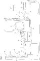
- the counter-spindle turning machine shown has a non-displaceable headstock 20 and a headstock 20a that can be displaced in the Z-direction.
- a workpiece spindle is mounted as a rotatable machine part 1 or 1a.
- the workpiece spindles carry clamping devices 21, 21a facing one another.
- the headstocks 20 and 20a are attached to a machine bed on which a longitudinal slide 3a can be moved in the Z-direction.
- a cross slide 3b is guided on the longitudinal slide 3a, on which a tool carrier is pivotably mounted about a horizontal axis.
- the tool carrier 24 has a tool holder into which tools (not shown), a probe 5 and a housing of a calibration gauge 4 can be inserted.
- a tool store 2 with storage locations 22 in the form of a tool magazine is arranged at one end of the counter-spindle lathe, in which a probe 5, the housing 9 and tools can be accommodated.
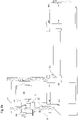
- FIG 2 illustrates the overall structure of a calibration device 19 according to the invention. It has a housing with a sleeve 11, which is followed by a holder shaft 14, at the end of which a short taper shaft 13 is formed is with which the calibration device 19 according to the invention can be inserted into the tool holder 10 .
- the sleeve 11 is made of CFRP material, but it can be made of another thin-walled material.
- the sleeve 11 protects a calibration standard 8, which is designed as a measuring ball and is accommodated in it, from contamination.
- the calibration device 19 according to the invention has a base 6 which is provided with magnetic feet 7 by means of which the calibration device 19 according to the invention can be fixed to the clamping device 21 .
- the mounting position of the calibration device 19 according to the invention in this exemplary embodiment is such that the calibration standard 8 is arranged concentrically to the axis of rotation of the rotatable machine part 1 .
- the short taper shank 13 and the holder shank 14 have a bore 15 through which sealing air is passed into the interior space formed by the sleeve 11 in order to prevent the ingress of dirt.
- the sleeve 11 is followed by a ring element 15 in which notches 12 are provided distributed over the circumference.
- the catches 12 hold the calibration gauge during transport in the sleeve 11 in such a way that the base 6 is freely accessible and can be fixed to the fastening device 21 with its magnetic feet 7 .
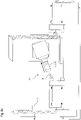
- the figures 4 and 5 and 6 and 7 illustrate different embodiments of the interface for attaching a part of the calibration device according to the invention to the machine section to be measured.
- figure 4 shows the part of the calibration device according to the invention to be fastened to the machine section, comprising the calibration standard and the interface for receiving it on the fastening device on the machine section, which is used in the exemplary embodiment of FIG figure 4 formed by a base 6 is, which has magnetic feet 7.
- the figure 5 shows this part of the calibration device according to the invention in cross section.
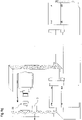
- Figure 8a shows the receiving of a calibration device 19 according to the invention, which is stored in a tool store 22, by a receiving device 24, which in this exemplary embodiment is designed as a tool carrier with a tool holder 10, which in this exemplary embodiment serves as an interface on the receiving device side for receiving the calibration device 19 according to the invention.
- a probe 5 is also mounted in the tool magazine 2 .
- the receiving device is moved via the two carriages 3a, 3b to a fastening position of the calibration device according to the invention in a fastening device on a tool section 21, as shown in FIG Figure 8b illustrated.
- the receiving device 24 in the present embodiment, the tool carrier with tool holder 10, after fixing of the part of the calibration device according to the invention with the calibration standard 8 removed from the machine section.
- the sleeve 11 with the interface of the calibration device according to the invention is pulled off for receiving on the receiving device in the form of the conical shank 13, so that the calibration standard 8 is exposed for measurement using the probe 5.
- this probe 5 is received by the receiving device in the tool magazine 2 and a sensor 5a is arranged in a measuring position B by moving the receiving device 24 in the vicinity of the calibration standard 8, which is designed as a measuring ball; see. Figure 8d .
- the workpiece spindle 1 is rotated and in this way brought the eccentrically arranged calibration standard into a second measuring position C, in which it is also measured by the probe.
- the Figures 8f and 8g illustrate the procedural steps of removing the calibration device according to the invention from the machine section to be measured by receiving the calibration standard 8 in the sleeve 11 and releasing it from the attachment to the machine section, which follows as a procedural step after the probe is placed in the tool magazine (not shown). Finally, as in Figure 8g illustrated, the entire calibration device according to the invention is stored in the tool magazine 2 .
- the present invention is not limited to this, but also includes configurations in which the entire calibration device according to the invention, including the interface is attached to the receiving device on the corresponding machine part for recording and remains there during the measuring process.
Description
Die vorliegende Erfindung betrifft eine Vorrichtung zum Vermessen einer Werkzeugmaschine mit einer Kalibriereinrichtung, eine entsprechende Kalibriereinrichtung und ein zugehöriges Verfahren.The present invention relates to a device for measuring a machine tool with a calibration device, a corresponding calibration device and an associated method.
Aus dem Stand der Technik sind zahlreiche Verfahren bekannt mittels derer Maschinenkomponenten der Werkzeugmaschine in Bezug auf ihre Lageposition vermessen werden können. In der Regel wird hierzu auf dem zu vermessenden Maschinenteil, insbesondere dem Werkstücktisch, eine Kalibriereinrichtung montiert und anschließend werden mittels eines häufig in der Arbeitsspindel gespannten Messtasters verschiedene Lagepositionen eines Kalibriernormals der Kalibriereinrichtung erfasst und aus den ermittelten Positionen die Lage des entsprechenden Maschinenteils ermittelt.Numerous methods are known from the prior art, by means of which machine components of the machine tool can be measured in relation to their position. As a rule, a calibration device is mounted on the machine part to be measured, in particular the workpiece table, and then various positions of a calibration standard of the calibration device are recorded by means of a measuring probe, which is often clamped in the work spindle, and the position of the corresponding machine part is determined from the determined positions.
Derartige Messverfahren sind sowohl für Dreh- als auch für Fräsmaschinen beschrieben worden, die je nach Werkzeugmaschinentyp dann an die entsprechenden strukturellen Gegebenheiten angepasst sind.Such measuring methods have been described for both turning and milling machines, which are then adapted to the corresponding structural conditions depending on the type of machine tool.
Beispielsweise wird in der
Aus der
Aus der
Den aus dem Stand der Technik bekannten Verfahren ist es gemein, dass zur Vermessung der Werkzeugmaschine aufwendige Vorbereitungsarbeiten notwendig sind, die selbst dann erfolgen müssen, wenn der eigentliche Messvorgang nachfolgend in automatisierter Weise durchgeführt wird. Dies ist im Falle einer einmaligen Kalibrierung der Werkzeugmaschine zu Beginn des Bearbeitungsprozesses noch tolerierbar. Einer wiederholten Einmessung zur Erhöhung der Fertigungsgenauigkeit ist jedoch schon aus zeitlichen Gründen Grenzen gesetzt.It is common to the methods known from the prior art that measuring the machine tool requires complex preparatory work, which must be carried out even if the actual measuring process is subsequently carried out in an automated manner. In the case of a one-off calibration of the machine tool at the beginning of the machining process, this is still tolerable. A repeated measurement for Increasing the production accuracy is, however, already limited for reasons of time.
Aufgabe der Erfindung ist es, eine Vorrichtung zum Vermessen einer Werkzeugmaschine und ein zugehöriges Verfahren zum Vermessen einer Werkzeugmaschine unter Verwendung einer Kalibriereinrichtung anzugeben, die den Aufwand des Messvorgangs beim Vermessen einer Werkzeugmaschine mit einer Kalibriereinrichtung reduzieren.The object of the invention is to specify a device for measuring a machine tool and an associated method for measuring a machine tool using a calibration device, which reduce the complexity of the measuring process when measuring a machine tool with a calibration device.
Diese Aufgaben werden durch eine Vorrichtung zum Vermessen einer Werkzeugmaschine mit einer Kalibriereinrichtung mit den Merkmalen des Patentanspruchs 1 und ein Verfahren zum Vermessen einer Werkzeugmaschine mit einer Kalibriereinrichtung mit den Merkmalen des Patentanspruchs 13 gelöst. Die zugehörigen Unteransprüche geben jeweils bevorzugte Ausgestaltungen der Erfindung an.These objects are achieved by a device for measuring a machine tool with a calibrating device having the features of
Die erfindungsgemäße Vorrichtung zum Vermessen einer Werkzeugmaschine umfasst eine Kalibriereinrichtung, die dazu eingerichtet ist, an einem Abschnitt der Werkzeugmaschine befestigt zu werden, und einen verfahrbaren Messtaster zur Erfassung einer Position der Kalibriereinrichtung an der Werkzeugmaschine. Erfindungsgemäß weist die Kalibriereinrichtung eine Schnittstelle auf mittels derer sie in eine numerisch verfahrbare Aufnahmeeinrichtung der Werkzeugmaschine ein- und auswechselbar ist, mit der die Kalibriereinrichtung zwischen einer Bereitstellungsposition und einer Befestigungsposition an dem Abschnitt der Werkzeugmaschine transportierbar ist.The device according to the invention for measuring a machine tool comprises a calibration device, which is set up to be attached to a section of the machine tool, and a movable probe for detecting a position of the calibration device on the machine tool. According to the invention, the calibration device has an interface by means of which it can be inserted and exchanged in a numerically movable receiving device of the machine tool, with which the calibration device can be transported between a ready position and a fastening position on the section of the machine tool.
Die Bereitstellungsposition kann in einem Speicher, etwa in einem Magazin oder einem Revolver für Werkzeuge oder Werkstücke, sein, in dem die Kalibriereinrichtung aufgenommen ist, oder in einer Zwischenposition.The ready position can be in a store, for example in a magazine or a turret for tools or workpieces, in which the calibration device is accommodated, or in an intermediate position.
Die erfindungsgemäße Vorrichtung umfasst demnach eine Kalibriereinrichtung, die neben einer (ersten) Schnittstelle zur Befestigung an einem Abschnitt der Werkzeugmaschine eine weitere (zweite) Schnittstelle aufweist, mittels derer sie in einer numerisch verfahrbaren Aufnahmeeinrichtung der Werkzeugmaschine aufgenommen werden kann, mittels derer sie in eine Befestigungsposition an einen zu vermessenden Maschinenabschnitt zugestellt werden kann.The device according to the invention therefore comprises a calibration device which, in addition to a (first) interface for attachment to a section of the machine tool, has a further (second) interface, by means of which it can be received in a numerically movable receiving device of the machine tool, by means of which it can be moved to a fastening position can be delivered to a machine section to be measured.
Auf diese Weise kann die Kalibriereinrichtung der erfindungsgemäßen Vorrichtung durch die numerisch verfahrbare Aufnahmeeinrichtung aufgenommen und verfahren werden, was erstmals einen vollständig automatisierten Ablauf des Vermessens einer Werkzeugmaschine ermöglicht. Auf diese Weise werden Unterbrechungen des Produktionsvorgangs an der Werkzeugmaschine, die infolge von Vorbereitungsmaßnahmen für das Vermessen der Werkzeugmaschine zu unzumutbaren Verzögerungen der Produktion führen, reduziert bzw. vollständig vermieden. Ein sonst erforderliches manuelles Vorbereiten durch Öffnen der Arbeitsraumtüren, was zu einer negativen thermischen Beeinflussung der Werkzeugmaschine führen kann, kann ebenfalls vermieden werden.In this way, the calibration device of the device according to the invention can be picked up and moved by the numerically movable recording device, which for the first time allows a fully automated process of the Measuring a machine tool allows. In this way, interruptions in the production process on the machine tool, which lead to unreasonable delays in production as a result of preparatory measures for measuring the machine tool, are reduced or completely avoided. Manual preparation that would otherwise be required by opening the work area doors, which can lead to a negative thermal effect on the machine tool, can also be avoided.
Die Aufnahmeeinrichtung richtet sich vorwiegend nach dem Typ und der Bauart der Werkzeugmaschine. Sie kann als Komponente der Werkzeugmaschine grundsätzlich vorbekannt sein. Im Falle einer Drehmaschine kann dies ein Werkzeugträger mit zugehörigem Werkzeugschlitten sein. Im Falle einer Fräsmaschine oder eines Fräszentrums zur Komplettbearbeitung kann die Aufnahmeeinrichtung auch als Spindel vorgesehen sein, die bei der Bearbeitung des Werkstücks das entsprechende Werkzeug aufnimmt.The receiving device depends primarily on the type and design of the machine tool. In principle, it can be previously known as a component of the machine tool. In the case of a lathe, this can be a tool carrier with an associated tool slide. In the case of a milling machine or a milling center for complete machining, the receiving device can also be provided as a spindle, which receives the corresponding tool when machining the workpiece.
Bei einem besonders bevorzugten Ausführungsbeispiel der erfindungsgemäßen Kalibriereinrichtung ist diese mehrteilig aufgebaut, bestehend aus einem ersten Teil, der die Schnittstelle zur Aufnahme an der Aufnahmeeinrichtung umfasst und einem davon lösbaren zweiten Teil, der das Kalibriernormal und die Schnittstelle zur Befestigung an einem Maschinenteil umfasst. Dieser zweite Teil kann ebenfalls aus mehreren, miteinander lösbar verbundenen Komponenten bestehen, muss dies aber nicht zwangsläufig. Wesentlich bei dieser Ausgestaltung ist es, dass beispielsweise das Kalibriernormal und die Schnittstelle zur Befestigung an einem Maschinenteil an dem zu vermessenden Maschinenabschnitt befestigt werden können, ohne dass die Verbindung der Schnittstelle zur Befestigung der erfindungsgemäßen Kalibriereinrichtung an der Aufnahmeeinrichtung gelöst werden muss. So ist es beispielsweise möglich, das Kalibriernormal an dem entsprechenden Maschinenabschnitt zu fixieren und die Schnittstelle zur Befestigung der erfindungsgemäßen Kalibriereinrichtung an der Aufnahmeeinrichtung in einfacher Weise abzuziehen, ohne dass die Verbindung des Kalibriernormals mit dem entsprechenden Maschinenteil gelöst wird.In a particularly preferred embodiment of the calibration device according to the invention, this is constructed in several parts, consisting of a first part, which includes the interface for receiving on the receiving device and a second part, which can be detached from it and includes the calibration standard and the interface for attachment to a machine part. This second part can also consist of several components that are detachably connected to one another, but this does not necessarily have to be the case. It is essential in this configuration that, for example, the calibration standard and the interface for attachment to a machine part can be attached to the machine section to be measured without having to disconnect the interface for attachment of the calibration device according to the invention to the receiving device. For example, it is possible to fix the calibration standard to the corresponding machine section and to deduct the interface for attaching the calibration device according to the invention to the receiving device in a simple manner, without the connection of the calibration standard with the corresponding machine part.
Die Schnittstelle, mittels derer die erfindungsgemäße Kalibriereinrichtung in eine numerisch verfahrbare Aufnahmeeinrichtung der Werkzeugmaschine eingesetzt werden kann, weist einen Halter auf, in den ein Kalibriernormal der Kalibriereinrichtung einsetzbar ist. Dieser Halter weist ein das Kalibriernormal umgebendes Schutzgehäuse auf. Dieses Schutzgehäuse kann zweckmäßigerweise aus einer dünnwandigen flexiblen Hülse bestehen. Auf diese Weise wird das Kalibriernormal vor Verschmutzung zuverlässig geschützt. Bei einem bevorzugten Ausführungsbeispiel ist die Hülse aus einem kohlefaserverstärkten Verbundwerkstoff (CFK) gefertigt.The interface, by means of which the calibration device according to the invention can be inserted into a numerically movable receiving device of the machine tool, has a holder into which a calibration standard of the calibration device can be inserted. This holder has a protective housing surrounding the calibration standard. This protective housing can suitably consist of a thin-walled, flexible sleeve. In this way, the calibration standard is reliably protected from contamination. In a preferred embodiment, the sleeve is made from a carbon fiber reinforced composite (CFRP).
Die Schnittstelle zur Aufnahme der Kalibriereinrichtung in der Aufnahmeeinrichtung kann als Kegelschaft, Hohlschaftkegel (HSK), etc. ausgebildet sein und ist in ihrer bevorzugten Ausgestaltung eine beliebige vorbekannte Schnittstelle zum Spannen eines Werkzeugs. Die Aufnahmeeinrichtung kann in diesem Zusammenhang auch zur Aufnahme angetriebener Werkzeuge ausgestaltet sein. In solchen Fällen bietet sich etwa eine HSK-Schnittstelle an, mittels derer die Kalibriereinrichtung in die Aufnahmeeinrichtung aufgenommen werden kann.The interface for accommodating the calibration device in the accommodating device can be designed as a conical shank, hollow shank cone (HSK), etc. and, in its preferred embodiment, is any previously known interface for clamping a tool. In this context, the holding device can also be designed to hold driven tools. In such cases, an HSK interface can be used, for example, by means of which the calibration device can be accommodated in the receiving device.
Bei der Schnittstelle zur Befestigung der erfindungsgemäßen Kalibriereinrichtung an einem Maschinenabschnitt kann es sich etwa um einen Magnetfuß handeln, mittels dessen die Kalibriereinrichtung an dem Maschinenabschnitt befestigbar ist. Die Kalibriereinrichtung kann aber auch beispielweise einen Einspannabschnitt aufweisen, insbesondere in Form eines Sockels, mittels dessen die Kalibriereinrichtung in eine Befestigungseinrichtung an dem Maschinenabschnitt gespannt werden kann.The interface for attaching the calibration device according to the invention to a machine section can be a magnetic base, by means of which the calibration device can be attached to the machine section. However, the calibration device can also have a clamping section, for example, in particular in the form of a base, by means of which the calibration device can be clamped in a fastening device on the machine section.
Im Falle einer Drehmaschine ist es zweckmäßig, etwa eine entsprechende Spannvorrichtung an einer drehbaren Werkstückspindel vorzusehen, die dann als Einrichtung zur Befestigung der Kalibriereinrichtung an dem Maschinenabschnitt fungiert, wobei die Spannvorrichtung in einer Position zur Erfassung der exakten Drehachse der drehbaren Werkstückspindel vorgesehen ist.In the case of a lathe, it is expedient to provide a corresponding clamping device on a rotatable workpiece spindle, which then acts as a means for attaching the calibration device to the machine section, with the clamping device being provided in a position for detecting the exact axis of rotation of the rotatable workpiece spindle.
Bei einem besonders zweckmäßigen Ausführungsbeispiel weist das Gehäuse Sensorelemente auf, mittels derer eine Deformation des Gehäuses der Kalibriereinrichtung erfasst werden kann. In diesem Fall ist die Werkzeugmaschine derart konfiguriert, dass nach Erfassung einer Deformation des Gehäuses die Verfahrbewegung der Aufnahmeeinrichtung automatisch gestoppt wird. Auf diese Weise kann sichergestellt werden, dass das Kalibriernormal, das z.B. in der Hülse geschützt ist, beim Einsetzen in die Befestigungsvorrichtung an dem Maschinenabschnitt oder beim sonstigen Verfahren nicht beschädigt werden kann.In a particularly expedient exemplary embodiment, the housing has sensor elements, by means of which a deformation of the housing of the calibration device can be detected. In this case, the machine tool is configured in such a way that after a deformation of the housing has been detected, the movement of the receiving device is automatically stopped. In this way it can be ensured that the calibration standard, which is protected in the sleeve, for example, cannot be damaged when it is inserted into the fastening device on the machine section or during any other procedure.
Eine mit der erfindungsgemäßen Vorrichtung zum Vermessen einer Werkzeugmaschine ausgestattete Werkzeugmaschine kann einen Speicher, vorzugsweise ein Werkzeugmagazin oder einen Werkzeugrevolver, aufweisen, in dem die Kalibriereinrichtung, der Messtaster sowie Werkzeuge und/oder Werkstücke gespeichert werden können, die durch die Aufnahmeeinrichtung oder einen Manipulator, der an die Aufnahmeeinrichtung zustellt, entnommen werden können. Im Falle einer Drehmaschine kann es sich um einen Werkzeugspeicher handeln, der als Werkzeugrevolver ausgebildet ist und in dessen Werkzeugaufnahme ein geschützter Platz für Messtaster und ein Platz für den Halter vorgesehen sind, der das Kalibriernormal der Kalibriereinrichtung aufnimmt. Auch ein Kreuzschlitten mit einer Mehrzahl von Werkzeugaufnahmen kann zweckmäßigerweise als Werkzeugspeicher dienen.A machine tool equipped with the device according to the invention for measuring a machine tool can have a memory, preferably a tool magazine or a tool turret, in which the calibration device, the probe and tools and/or workpieces can be stored, which can be stored by the recording device or a manipulator that delivered to the receiving facility, can be removed. In the case of a lathe, it can be a tool store that is designed as a tool turret and in whose tool holder there is a protected place for the probe and a place for the holder that accommodates the calibration standard of the calibration device. A compound slide with a plurality of tool holders can also be used as a tool store.
Bei einem bevorzugten Ausführungsbeispiel weist das Gehäuse zudem Haltemittel wie z.B. Rasten auf, mittels derer die Kalibriereinrichtung während des Transports in dem Gehäuse gehaltert wird dergestalt, dass die Schnittstelle zur Befestigung der Kalibriereinrichtung an einem Maschinenabschnitt der Werkzeugmaschine frei zugänglich ist, sodass die Kalibriereinrichtung ohne Weiteres an der Befestigungseinrichtung befestigt werden kann. Dies kann zweckmäßigerweise über die bereits angesprochenen Magnetfüße oder über eine Ausgestaltung eines Sockels der Kalibriereinrichtung als Spannscheibe, die etwa in einem Spannfutter eingespannt wird, erfolgen.In a preferred embodiment, the housing also has holding means such as catches, by means of which the calibration device is held in the housing during transport in such a way that the interface for attaching the calibration device to a machine section of the machine tool is freely accessible, so that the calibration device can be easily attached the Fastening device can be attached. This can expediently take place via the magnetic bases already mentioned or via a configuration of a base of the calibration device as a clamping disk, which is clamped in a clamping chuck, for example.
Die Erfindung umfasst auch ein Verfahren zum Vermessen einer Werkzeugmaschine mit einer erfindungsgemäßen Kalibriereinrichtung, wobei das Verfahren die Schritte umfasst:
Bereitstellen einer Kalibriereinrichtung in einem Speicher zur Aufnahme von Werkzeugen und/oder Werkstücken, Verfahren einer Aufnahmeeinrichtung in eine Position nahe des Speichers zur Aufnahme der Kalibriereinrichtung und Entnahme aus dem Speicher, Aufnehmen der Kalibriereinrichtung durch die Aufnahmeeinrichtung und Verfahren der Aufnahmeeinrichtung in eine Position nahe einer an einem zu vermessendem Werkzeugmaschinenabschnitt vorgesehenen Einrichtung zur Befestigung der Kalibriereinrichtung an dem Maschinenabschnitt, Befestigen der Kalibriereinrichtung an dem Maschinenabschnitt durch Verfahren der Aufnahmeeinrichtung in eine Befestigungsposition an dem Maschinenabschnitt und Aufnahme in der an dem Maschinenabschnitt angeordneten Befestigungseinrichtung und Vermessen einer Position der Kalibriereinrichtung an dem Maschinenabschnitt mit einem Messtaster.The invention also includes a method for measuring a machine tool with a calibration device according to the invention, the method including the steps:
Providing a calibration device in a store for receiving tools and/or workpieces, moving a receiving device to a position close to the store to receive the calibration device and removing it from the store, receiving the calibration device by the receiving device and moving the receiving device to a position near a a machine tool section to be measured, for fastening the calibration device to the machine section, fastening the calibration device to the machine section by moving the receiving device into a fastening position on the machine section and receiving it in the fastening device arranged on the machine section, and measuring a position of the calibration device on the machine section with a probe.
Der Schritt des Vermessens einer Position der Kalibriereinrichtung an dem Maschinenabschnitt mit dem Messtaster kann vorzugsweise die Schritte Verfahren der Aufnahmeeinrichtung zu einem Speicher, Aufnehmen des Messtasters aus dem Speicher, Verfahren der Aufnahmeeinrichtung mit dem Messtaster in einer Messposition nahe der an dem Maschinenabschnitt befestigten Kalibriereinrichtung und Vermessen mehrerer Positionen eines Kalibriernormals der Kalibriereinrichtung und Ermitteln einer Position des Maschinenabschnitts aus den ermittelten Messpositionen umfassen.The step of measuring a position of the calibration device on the machine section with the probe can preferably include the steps of moving the recording device to a memory, picking up the probe from the memory, moving the recording device with the probe to a measuring position close to the calibration device attached to the machine section, and measuring several positions of a calibration standard of the calibration device and determining a position of the machine section from the determined measurement positions.
Das erfindungsgemäße Verfahren erlaubt eine vollautomatisierte Durchführung des Verfahrens zum Vermessen einer Werkzeugmaschine zur Kalibrierung, in dem die Positionierung und Befestigung der Kalibriereinrichtung an dem zu vermessenden Maschinenteil in ähnlicher Weise mittels einer durch CNC-Steuerung verfahrbaren Vorrichtung vorgenommen wird, wie das Einwechseln eines Werkzeugs an einer programmgesteuerten Werkzeugmaschine. Dies wird ermöglicht durch die konstruktive Ausgestaltung der erfindungsgemäßen Kalibriereinrichtung mit Schnittstellen, die einerseits eine Aufnahme in der Aufnahmeeinrichtung und andererseits eine automatisierbare Befestigung an einem zu vermessendem Maschinenteil ermöglichen.The method according to the invention allows a fully automated implementation of the method for measuring a machine tool for calibration, in which the positioning and attachment of the calibration device to the machine part to be measured is carried out in a similar way by means of a device that can be moved by CNC control, such as changing a tool on a program-controlled machine tool. This is made possible by the structural design of the calibration device according to the invention with interfaces which, on the one hand, enable recording in the recording device and, on the other hand, automatic attachment to a machine part to be measured.
Auf diese Weise kann der Vorgang des Vermessens vollständig in den Prozessablauf zur Bearbeitung eines Werkstücks an der Werkzeugmaschine integriert werden, sodass keine Unterbrechungen und aufwendige Vorbereitungen der Werkzeugmaschine von Nöten ist.In this way, the process of measuring can be fully integrated into the process flow for machining a workpiece on the machine tool, so that no interruptions and complex preparations of the machine tool are necessary.
Bevorzugte Ausführungsformen und Einzelheiten der Erfindung werden nachfolgend anhand der Figuren beschrieben, in denen
Figur 1- eine Gegenspindel-Drehmaschine mit erfindungsgemäßer Vorrichtung zum Vermessen einer Werkzeugmaschine in schematischer Darstellung,
Figur 2- eine erfindungsgemäße Kalibriereinrichtung mit einem Halter mit eingesetztem Kalibriernormal,
Figur 3- den Halter gemäß
Figur 2 Figur 4- eine erfindungsgemäße Kalibriereinrichtung mit Magnetfuß zur Befestigung an einem zu vermessenden Maschinenabschnitt,
Figur 5- die
Kalibriereinrichtung gemäß Figur 4 im Querschnitt, Figur 6- eine erfindungsgemäße Kalibriereinrichtung mit zylindrischer Spannscheibe zur Befestigung in einer Spanneinrichtung an einem Werkzeugmaschinenabschnitt,
Figur 7- die erfindungsgemäße Kalibriereinrichtung gemäß
Figur 6 im Querschnitt, und - Figur 8a - 8g
- ein Ausführungsbeispiel des erfindungsgemäßen Verfahrens zum Vermessen einer Werkzeugmaschine mittels einer Kalibriereinrichtung
- figure 1
- a counter-spindle lathe with a device according to the invention for measuring a machine tool in a schematic representation,
- figure 2
- a calibration device according to the invention with a holder with an inserted calibration standard,
- figure 3
- according to the holder
figure 2 in cross section, - figure 4
- a calibration device according to the invention with a magnetic base for attachment to a machine section to be measured,
- figure 5
- the calibration device according to
figure 4 in cross section, - figure 6
- a calibration device according to the invention with a cylindrical Clamping disc for attachment in a clamping device on a machine tool section,
- figure 7
- the calibration device according to the invention
figure 6 in cross section, and - Figure 8a - 8g
- an embodiment of the method according to the invention for measuring a machine tool by means of a calibration device
Die erfindungsgemäße Vorrichtung zum Vermessen einer Werkzeugmaschine wird nachfolgend am Beispiel einer Drehmaschine beschrieben, wenngleich die erfindungsgemäße Vorrichtung auch mit anderen Werkzeugmaschinentypen, wie z.B. Fräszentren, realisiert werden kann.The device according to the invention for measuring a machine tool is described below using the example of a lathe, although the device according to the invention can also be implemented with other types of machine tools, such as milling centers.
Die in
Wie in der
Die
Bei den Alternativen des in
Ein Ausführungsbeispiel des erfindungsgemäßen Verfahrens zur Vermessung einer Werkzeugmaschine wird im Folgenden anhand der
Im nächsten Schritt erfolgt ein Verfahren der Aufnahmeeinrichtung über die beiden Schlitten 3a, 3b hin zu einer Befestigungsposition der erfindungsgemäßen Kalibriereinrichtung in einer Befestigungseinrichtung an einem Werkzeugabschnitt 21, wie in
Im nächsten Schritt wird die Aufnahmeeinrichtung 24, im vorliegenden Ausführungsbeispiel der Werkzeugträger mit Werkzeugaufnahme 10, nach Fixierung des Teils der erfindungsgemäßen Kalibriereinrichtung mit dem Kalibriernormal 8 an dem Maschinenabschnitt entfernt. Dabei wird, wie in
Dieser Messtaster 5 wird im nächsten Verfahrensschritt durch die Aufnahmeeinrichtung im Werkzeugmagazin 2 aufgenommen und ein Messfühler 5a wird durch Verfahren der Aufnahmeeinrichtung 24 in der Nähe des als Messkugel ausgestalteten Kalibriernormals 8 in einer Messposition B angeordnet; vgl.
Obgleich das erfindungsgemäße Verfahren am Beispiel einer zweiteiligen erfindungsgemäßen Kalibriereinrichtung, bei der nur ein Teil der Kalibriereinrichtung 19 an dem Maschinenabschnitt fixiert wird, beschrieben wurde, ist die vorliegende Erfindung nicht hierauf beschränkt, sondern umfasst auch Ausgestaltungen, bei denen die gesamte erfindungsgemäße Kalibriereinrichtung einschließlich der Schnittstelle zur Aufnahme an der Aufnahmeeinrichtung an dem entsprechenden Maschinenteil befestigt wird und während des Messvorgangs dort verbleibt.Although the method according to the invention has been described using the example of a two-part calibration device according to the invention, in which only part of the
Claims (14)
- A device for measuring a machine tool, comprising:- a calibration means (19) configured to be fastened to a portion of said machine tool, and- a measuring probe (5) for detecting a position of said calibration means (19) on said machine tool,characterized in that
wherein said calibration means (19) includes an interface (13) by means of which said calibration means (19) can be inserted into and removed from a numerically displaceable receiving means (24) of said machine tool, with which said calibration means can be transported between a ready position and a fastening position on the portion of said machine tool,said interface (13) includes a holder for inserting into or removing from said receiving means (24), a calibration standard (8) of said calibration means (19) being insertable into said holder,wherein said holder includes a protective case (9) surrounding said calibration standard (8). - The device for measuring a machine tool according to claim 1, characterized in that
said calibration standard (8) can be fastened to the machine portion by means of a second interface (6, 7; 6a). - The device for measuring a machine tool according to claim 1 or 2, characterized in that
said calibration means (19) is constructed of a plurality of parts, consisting of a first part which includes said interface (13) for receiving on said receiving means (24) and a second part which can be detached therefrom and which includes said calibration standard (8) and said interface (6, 7; 6a) for fastening to a machine part (1). - The device for measuring a machine tool according to one of the claims 1 to 3, characterized in that
said protective case (9) consists of a thin-walled flexible sleeve (11). - The device for measuring a machine tool according to one of the claims 1 to 4, characterized in that
said calibration means (19) is configured such that a signal for controlling a displacement operation of said receiving means (24) is generated by a deformation of said case (9). - The device for measuring a machine tool according to one of the claims 1 to 5, characterized in that
said calibration means (19) includes a magnetic foot (7) by means of which it can be fastened to the machine portion. - The device for measuring a machine tool according to one of the claims 1 to 6, characterized in that
said calibration means (19) includes a clamping portion, in particular in the form of a base (6a), by means of which said calibration means (19) can be clamped to the machine portion. - The device for measuring a machine tool according to one of the preceding claims, characterized in that
said calibration means (19) is detachably held on said holder by catches (12). - A calibration means (19) for use in a device for measuring a machine tool according to one of the claims 1 to 8,wherein said calibration means (19) includes an interface (13) by means of which said calibration means (19) can be inserted into and removed from a numerically displaceable receiving means (24) of said machine tool,wherein said interface (13) includes a holder for inserting into or removing from said receiving means (24), a calibration standard (8) of said calibration means (19) being insertable into said holder, andwherein said holder includes a protective case (9) surrounding said calibration standard (8).
- The machine tool including a calibration means (19) according to claim 9,wherein a machine portion (1) to which said calibration means (19) can be fastened comprises a rotatable workpiece spindle, andsaid machine tool comprises a means (21) for fastening said calibration means (19) to the machine portion (1) in a position eccentric with respect to the axis of the rotatable workpiece spindle.
- The machine tool including a calibration means (19) according to claim 9,
wherein a numerically displaceable receiving means (24) of said machine tool comprises a tool carrier (24) and at least one slide (3a, 3b) by means of which it can be moved to a position for fastening said calibration means (19) received in said tool carrier (24) to the machine portion (1). - The machine tool including a calibration means (19) according to claim 9,
wherein a numerically displaceable receiving means (24) is configured as a spindle into which said calibration means (19) and a measuring probe (5) can be inserted or from which they can be removed. - A method for measuring a machine tool including a calibration means (19), comprising the steps of:- providing a calibration means (19) according to claim 9 in a store (2) for receiving tools and/or workpieces,- moving a receiving means (24) to a position close to said store (2) for receiving said calibration means (19) and removing it from said store (2),- receiving said calibration means (19) by means of said receiving means (24) and moving said receiving means (24) to a position close to a means (21) for fastening said calibration means (19) to said machine portion (1), said means (21) being provided on a machine tool portion (1),- fastening said calibration means (19) to said machine portion (1) by moving said receiving means (24) into a fastening position on the machine portion (1) and receiving it in a fastening means (21) arranged on the machine portion (1), and- measuring a position of said calibration means (19) on the machine portion with a measuring probe (5).
- The method according to claim 13, characterized in that
the step of measuring a position of said calibration means (19) on the machine portion (1) with said measuring probe (5) comprises the steps of:- moving said receiving means (24) to a store (2),- receiving said measuring probe (5) from said store (2),- moving said receiving means (24) with said measuring probe (5) into a measuring position close to said calibration means (19) fastened to the machine portion (1),- measuring a plurality of positions of a calibration standard (8) of said calibration means (19), and- determining a position of the machine portion (1) from the determined measuring positions.
Priority Applications (1)
| Application Number | Priority Date | Filing Date | Title |
|---|---|---|---|
| EP17188015.6A EP3446830B1 (en) | 2017-08-25 | 2017-08-25 | Device and method for measuring a machine tool |
Applications Claiming Priority (1)
| Application Number | Priority Date | Filing Date | Title |
|---|---|---|---|
| EP17188015.6A EP3446830B1 (en) | 2017-08-25 | 2017-08-25 | Device and method for measuring a machine tool |
Publications (2)
| Publication Number | Publication Date |
|---|---|
| EP3446830A1 EP3446830A1 (en) | 2019-02-27 |
| EP3446830B1 true EP3446830B1 (en) | 2022-11-30 |
Family
ID=59702644
Family Applications (1)
| Application Number | Title | Priority Date | Filing Date |
|---|---|---|---|
| EP17188015.6A Active EP3446830B1 (en) | 2017-08-25 | 2017-08-25 | Device and method for measuring a machine tool |
Country Status (1)
| Country | Link |
|---|---|
| EP (1) | EP3446830B1 (en) |
Families Citing this family (1)
| Publication number | Priority date | Publication date | Assignee | Title |
|---|---|---|---|---|
| CN115422813B (en) * | 2022-11-03 | 2023-02-10 | 北京精雕科技集团有限公司 | Dynamics analysis method and device for machine tool road transportation working condition |
Family Cites Families (4)
| Publication number | Priority date | Publication date | Assignee | Title |
|---|---|---|---|---|
| DE102005008055B4 (en) | 2005-02-22 | 2009-01-02 | Deckel Maho Pfronten Gmbh | Method for measuring a program-controlled machine tool |
| GB0525306D0 (en) | 2005-12-13 | 2006-01-18 | Renishaw Plc | Method of machine tool calibration |
| SK288259B6 (en) * | 2011-10-21 | 2015-04-01 | Microstep Spol. S R.O. | CNC plasma cutting machine, oxygen and water jet cutting as a tool for auto-adjusting the exact position of the cutting tool in the cutting head autocalibration and how such a setup |
| DE102015226387B4 (en) * | 2015-12-21 | 2023-07-27 | Carl Zeiss Industrielle Messtechnik Gmbh | Procedure for performing measurements with a test element in a coordinate measuring machine or a machine tool |
-
2017
- 2017-08-25 EP EP17188015.6A patent/EP3446830B1/en active Active
Also Published As
| Publication number | Publication date |
|---|---|
| EP3446830A1 (en) | 2019-02-27 |
Similar Documents
| Publication | Publication Date | Title |
|---|---|---|
| EP3048413B1 (en) | Measuring machine for measuring workpieces | |
| EP1554080B1 (en) | Tool holding device and method for positioning a tool | |
| DE102015015094A1 (en) | Cooperation system with machine tool and robot | |
| DE102013106427A1 (en) | Method for providing tools and associated devices | |
| EP2303523A1 (en) | Machining installation for workpieces | |
| DE102006039258B4 (en) | Tool measuring method with a measuring device and measuring device with a tool measuring tool | |
| DE102008055795A1 (en) | Grinding machine, particularly vertical grinding machine, has measuring device and workpiece spindle unit with clamping device for clamping workpiece, where fist grinding unit is provided for grinding workpiece | |
| DE19734301C1 (en) | Machine for preparing parts for turning | |
| EP0123956B1 (en) | Cylindrical grinding machine for external and internal grinding with a numerical control device | |
| DE102011082839A1 (en) | Handling device e.g. gantry loader, for loading chuck of tool spindle of machine tool for e.g. lathe with bar-like workpiece to process workpiece, has guide assemblies loading chuck with workpiece from sides of workspace | |
| DE112006003145B4 (en) | Feeding device for a cutting tool for internal machining | |
| DE202016008624U1 (en) | Machine tool for machining workpieces | |
| DE102016220177A1 (en) | Method for processing a component and processing device | |
| EP0789221A2 (en) | Method for measuring the coordinates of work pieces on working machines | |
| DE102012105842B3 (en) | Machine tool, in particular grinding machine, and method for machining workpieces | |
| EP3446830B1 (en) | Device and method for measuring a machine tool | |
| DE4414747A1 (en) | Measuring tool (measuring device, gauge), in particular for measuring areas | |
| DE3634018C2 (en) | ||
| EP1169158B1 (en) | Method and device for machining workpieces | |
| EP2080585B1 (en) | Monitoring device | |
| DE102014112208B4 (en) | Machine tool and method for automatic assembly | |
| DE10361920B4 (en) | Apparatus and method for controlling tools | |
| DE102010007890B4 (en) | Machine tool for machining slender workpieces | |
| AT514068A4 (en) | Assembly device for a CAD / CAM milling device | |
| DE102013205038A1 (en) | Lathe or turning / milling center for machining workpieces and method for measuring the workpieces with a lathe or a turning / milling center |
Legal Events
| Date | Code | Title | Description |
|---|---|---|---|
| PUAI | Public reference made under article 153(3) epc to a published international application that has entered the european phase |
Free format text: ORIGINAL CODE: 0009012 |
|
| STAA | Information on the status of an ep patent application or granted ep patent |
Free format text: STATUS: THE APPLICATION HAS BEEN PUBLISHED |
|
| AK | Designated contracting states |
Kind code of ref document: A1 Designated state(s): AL AT BE BG CH CY CZ DE DK EE ES FI FR GB GR HR HU IE IS IT LI LT LU LV MC MK MT NL NO PL PT RO RS SE SI SK SM TR |
|
| AX | Request for extension of the european patent |
Extension state: BA ME |
|
| STAA | Information on the status of an ep patent application or granted ep patent |
Free format text: STATUS: REQUEST FOR EXAMINATION WAS MADE |
|
| 17P | Request for examination filed |
Effective date: 20190827 |
|
| RBV | Designated contracting states (corrected) |
Designated state(s): AL AT BE BG CH CY CZ DE DK EE ES FI FR GB GR HR HU IE IS IT LI LT LU LV MC MK MT NL NO PL PT RO RS SE SI SK SM TR |
|
| STAA | Information on the status of an ep patent application or granted ep patent |
Free format text: STATUS: EXAMINATION IS IN PROGRESS |
|
| STAA | Information on the status of an ep patent application or granted ep patent |
Free format text: STATUS: EXAMINATION IS IN PROGRESS |
|
| 17Q | First examination report despatched |
Effective date: 20211020 |
|
| GRAP | Despatch of communication of intention to grant a patent |
Free format text: ORIGINAL CODE: EPIDOSNIGR1 |
|
| STAA | Information on the status of an ep patent application or granted ep patent |
Free format text: STATUS: GRANT OF PATENT IS INTENDED |
|
| INTG | Intention to grant announced |
Effective date: 20220706 |
|
| RIN1 | Information on inventor provided before grant (corrected) |
Inventor name: HALM, CHRISTIAN Inventor name: LITWINSKI, KAI Inventor name: BASSETT, EDMOND |
|
| GRAJ | Information related to disapproval of communication of intention to grant by the applicant or resumption of examination proceedings by the epo deleted |
Free format text: ORIGINAL CODE: EPIDOSDIGR1 |
|
| STAA | Information on the status of an ep patent application or granted ep patent |
Free format text: STATUS: EXAMINATION IS IN PROGRESS |
|
| GRAP | Despatch of communication of intention to grant a patent |
Free format text: ORIGINAL CODE: EPIDOSNIGR1 |
|
| INTC | Intention to grant announced (deleted) | ||
| STAA | Information on the status of an ep patent application or granted ep patent |
Free format text: STATUS: GRANT OF PATENT IS INTENDED |
|
| GRAS | Grant fee paid |
Free format text: ORIGINAL CODE: EPIDOSNIGR3 |
|
| GRAA | (expected) grant |
Free format text: ORIGINAL CODE: 0009210 |
|
| STAA | Information on the status of an ep patent application or granted ep patent |
Free format text: STATUS: THE PATENT HAS BEEN GRANTED |
|
| INTG | Intention to grant announced |
Effective date: 20221013 |
|
| AK | Designated contracting states |
Kind code of ref document: B1 Designated state(s): AL AT BE BG CH CY CZ DE DK EE ES FI FR GB GR HR HU IE IS IT LI LT LU LV MC MK MT NL NO PL PT RO RS SE SI SK SM TR |
|
| REG | Reference to a national code |
Ref country code: CH Ref legal event code: EP Ref country code: GB Ref legal event code: FG4D Free format text: NOT ENGLISH |
|
| REG | Reference to a national code |
Ref country code: AT Ref legal event code: REF Ref document number: 1534318 Country of ref document: AT Kind code of ref document: T Effective date: 20221215 Ref country code: DE Ref legal event code: R096 Ref document number: 502017014142 Country of ref document: DE |
|
| REG | Reference to a national code |
Ref country code: IE Ref legal event code: FG4D Free format text: LANGUAGE OF EP DOCUMENT: GERMAN |
|
| REG | Reference to a national code |
Ref country code: SE Ref legal event code: TRGR |
|
| REG | Reference to a national code |
Ref country code: NL Ref legal event code: FP |
|
| REG | Reference to a national code |
Ref country code: LT Ref legal event code: MG9D |
|
| PG25 | Lapsed in a contracting state [announced via postgrant information from national office to epo] |
Ref country code: PT Free format text: LAPSE BECAUSE OF FAILURE TO SUBMIT A TRANSLATION OF THE DESCRIPTION OR TO PAY THE FEE WITHIN THE PRESCRIBED TIME-LIMIT Effective date: 20230331 Ref country code: NO Free format text: LAPSE BECAUSE OF FAILURE TO SUBMIT A TRANSLATION OF THE DESCRIPTION OR TO PAY THE FEE WITHIN THE PRESCRIBED TIME-LIMIT Effective date: 20230228 Ref country code: LT Free format text: LAPSE BECAUSE OF FAILURE TO SUBMIT A TRANSLATION OF THE DESCRIPTION OR TO PAY THE FEE WITHIN THE PRESCRIBED TIME-LIMIT Effective date: 20221130 Ref country code: FI Free format text: LAPSE BECAUSE OF FAILURE TO SUBMIT A TRANSLATION OF THE DESCRIPTION OR TO PAY THE FEE WITHIN THE PRESCRIBED TIME-LIMIT Effective date: 20221130 Ref country code: ES Free format text: LAPSE BECAUSE OF FAILURE TO SUBMIT A TRANSLATION OF THE DESCRIPTION OR TO PAY THE FEE WITHIN THE PRESCRIBED TIME-LIMIT Effective date: 20221130 |
|
| PG25 | Lapsed in a contracting state [announced via postgrant information from national office to epo] |
Ref country code: RS Free format text: LAPSE BECAUSE OF FAILURE TO SUBMIT A TRANSLATION OF THE DESCRIPTION OR TO PAY THE FEE WITHIN THE PRESCRIBED TIME-LIMIT Effective date: 20221130 Ref country code: PL Free format text: LAPSE BECAUSE OF FAILURE TO SUBMIT A TRANSLATION OF THE DESCRIPTION OR TO PAY THE FEE WITHIN THE PRESCRIBED TIME-LIMIT Effective date: 20221130 Ref country code: LV Free format text: LAPSE BECAUSE OF FAILURE TO SUBMIT A TRANSLATION OF THE DESCRIPTION OR TO PAY THE FEE WITHIN THE PRESCRIBED TIME-LIMIT Effective date: 20221130 Ref country code: IS Free format text: LAPSE BECAUSE OF FAILURE TO SUBMIT A TRANSLATION OF THE DESCRIPTION OR TO PAY THE FEE WITHIN THE PRESCRIBED TIME-LIMIT Effective date: 20230330 Ref country code: HR Free format text: LAPSE BECAUSE OF FAILURE TO SUBMIT A TRANSLATION OF THE DESCRIPTION OR TO PAY THE FEE WITHIN THE PRESCRIBED TIME-LIMIT Effective date: 20221130 Ref country code: GR Free format text: LAPSE BECAUSE OF FAILURE TO SUBMIT A TRANSLATION OF THE DESCRIPTION OR TO PAY THE FEE WITHIN THE PRESCRIBED TIME-LIMIT Effective date: 20230301 |
|
| PG25 | Lapsed in a contracting state [announced via postgrant information from national office to epo] |
Ref country code: SM Free format text: LAPSE BECAUSE OF FAILURE TO SUBMIT A TRANSLATION OF THE DESCRIPTION OR TO PAY THE FEE WITHIN THE PRESCRIBED TIME-LIMIT Effective date: 20221130 Ref country code: RO Free format text: LAPSE BECAUSE OF FAILURE TO SUBMIT A TRANSLATION OF THE DESCRIPTION OR TO PAY THE FEE WITHIN THE PRESCRIBED TIME-LIMIT Effective date: 20221130 Ref country code: EE Free format text: LAPSE BECAUSE OF FAILURE TO SUBMIT A TRANSLATION OF THE DESCRIPTION OR TO PAY THE FEE WITHIN THE PRESCRIBED TIME-LIMIT Effective date: 20221130 Ref country code: DK Free format text: LAPSE BECAUSE OF FAILURE TO SUBMIT A TRANSLATION OF THE DESCRIPTION OR TO PAY THE FEE WITHIN THE PRESCRIBED TIME-LIMIT Effective date: 20221130 Ref country code: CZ Free format text: LAPSE BECAUSE OF FAILURE TO SUBMIT A TRANSLATION OF THE DESCRIPTION OR TO PAY THE FEE WITHIN THE PRESCRIBED TIME-LIMIT Effective date: 20221130 |
|
| PG25 | Lapsed in a contracting state [announced via postgrant information from national office to epo] |
Ref country code: SK Free format text: LAPSE BECAUSE OF FAILURE TO SUBMIT A TRANSLATION OF THE DESCRIPTION OR TO PAY THE FEE WITHIN THE PRESCRIBED TIME-LIMIT Effective date: 20221130 Ref country code: AL Free format text: LAPSE BECAUSE OF FAILURE TO SUBMIT A TRANSLATION OF THE DESCRIPTION OR TO PAY THE FEE WITHIN THE PRESCRIBED TIME-LIMIT Effective date: 20221130 |
|
| REG | Reference to a national code |
Ref country code: DE Ref legal event code: R097 Ref document number: 502017014142 Country of ref document: DE |
|
| PGFP | Annual fee paid to national office [announced via postgrant information from national office to epo] |
Ref country code: NL Payment date: 20230823 Year of fee payment: 7 |
|
| PLBE | No opposition filed within time limit |
Free format text: ORIGINAL CODE: 0009261 |
|
| STAA | Information on the status of an ep patent application or granted ep patent |
Free format text: STATUS: NO OPPOSITION FILED WITHIN TIME LIMIT |
|
| PGFP | Annual fee paid to national office [announced via postgrant information from national office to epo] |
Ref country code: AT Payment date: 20230818 Year of fee payment: 7 |
|
| 26N | No opposition filed |
Effective date: 20230831 |
|
| PG25 | Lapsed in a contracting state [announced via postgrant information from national office to epo] |
Ref country code: SI Free format text: LAPSE BECAUSE OF FAILURE TO SUBMIT A TRANSLATION OF THE DESCRIPTION OR TO PAY THE FEE WITHIN THE PRESCRIBED TIME-LIMIT Effective date: 20221130 |
|
| PGFP | Annual fee paid to national office [announced via postgrant information from national office to epo] |
Ref country code: SE Payment date: 20230823 Year of fee payment: 7 Ref country code: DE Payment date: 20230831 Year of fee payment: 7 |
|
| PG25 | Lapsed in a contracting state [announced via postgrant information from national office to epo] |
Ref country code: MC Free format text: LAPSE BECAUSE OF FAILURE TO SUBMIT A TRANSLATION OF THE DESCRIPTION OR TO PAY THE FEE WITHIN THE PRESCRIBED TIME-LIMIT Effective date: 20221130 |
|
| REG | Reference to a national code |
Ref country code: CH Ref legal event code: PL |
|
| PG25 | Lapsed in a contracting state [announced via postgrant information from national office to epo] |
Ref country code: MC Free format text: LAPSE BECAUSE OF FAILURE TO SUBMIT A TRANSLATION OF THE DESCRIPTION OR TO PAY THE FEE WITHIN THE PRESCRIBED TIME-LIMIT Effective date: 20221130 |
|
| PG25 | Lapsed in a contracting state [announced via postgrant information from national office to epo] |
Ref country code: LU Free format text: LAPSE BECAUSE OF NON-PAYMENT OF DUE FEES Effective date: 20230825 |