EP3048386A1 - Freezer - Google Patents
Freezer Download PDFInfo
- Publication number
- EP3048386A1 EP3048386A1 EP14846460.5A EP14846460A EP3048386A1 EP 3048386 A1 EP3048386 A1 EP 3048386A1 EP 14846460 A EP14846460 A EP 14846460A EP 3048386 A1 EP3048386 A1 EP 3048386A1
- Authority
- EP
- European Patent Office
- Prior art keywords
- usage
- heat exchanger
- side heat
- stage compressor
- heat source
- Prior art date
- Legal status (The legal status is an assumption and is not a legal conclusion. Google has not performed a legal analysis and makes no representation as to the accuracy of the status listed.)
- Withdrawn
Links
- 239000003507 refrigerant Substances 0.000 claims abstract description 193
- 238000005057 refrigeration Methods 0.000 claims abstract description 41
- 230000007246 mechanism Effects 0.000 claims description 47
- 230000006835 compression Effects 0.000 claims description 7
- 238000007906 compression Methods 0.000 claims description 7
- 238000010438 heat treatment Methods 0.000 description 80
- 238000001816 cooling Methods 0.000 description 74
- 238000010586 diagram Methods 0.000 description 14
- 230000007704 transition Effects 0.000 description 7
- 230000008859 change Effects 0.000 description 4
- 238000004378 air conditioning Methods 0.000 description 3
- 238000001704 evaporation Methods 0.000 description 2
- 230000008020 evaporation Effects 0.000 description 2
- 238000000034 method Methods 0.000 description 2
- 230000008569 process Effects 0.000 description 2
- 230000005855 radiation Effects 0.000 description 2
- 230000004913 activation Effects 0.000 description 1
- 238000001514 detection method Methods 0.000 description 1
- 238000006073 displacement reaction Methods 0.000 description 1
- 230000000694 effects Effects 0.000 description 1
Images






Classifications
-
- F—MECHANICAL ENGINEERING; LIGHTING; HEATING; WEAPONS; BLASTING
- F25—REFRIGERATION OR COOLING; COMBINED HEATING AND REFRIGERATION SYSTEMS; HEAT PUMP SYSTEMS; MANUFACTURE OR STORAGE OF ICE; LIQUEFACTION SOLIDIFICATION OF GASES
- F25B—REFRIGERATION MACHINES, PLANTS OR SYSTEMS; COMBINED HEATING AND REFRIGERATION SYSTEMS; HEAT PUMP SYSTEMS
- F25B13/00—Compression machines, plants or systems, with reversible cycle
-
- F—MECHANICAL ENGINEERING; LIGHTING; HEATING; WEAPONS; BLASTING
- F25—REFRIGERATION OR COOLING; COMBINED HEATING AND REFRIGERATION SYSTEMS; HEAT PUMP SYSTEMS; MANUFACTURE OR STORAGE OF ICE; LIQUEFACTION SOLIDIFICATION OF GASES
- F25B—REFRIGERATION MACHINES, PLANTS OR SYSTEMS; COMBINED HEATING AND REFRIGERATION SYSTEMS; HEAT PUMP SYSTEMS
- F25B1/00—Compression machines, plants or systems with non-reversible cycle
- F25B1/10—Compression machines, plants or systems with non-reversible cycle with multi-stage compression
-
- F—MECHANICAL ENGINEERING; LIGHTING; HEATING; WEAPONS; BLASTING
- F25—REFRIGERATION OR COOLING; COMBINED HEATING AND REFRIGERATION SYSTEMS; HEAT PUMP SYSTEMS; MANUFACTURE OR STORAGE OF ICE; LIQUEFACTION SOLIDIFICATION OF GASES
- F25B—REFRIGERATION MACHINES, PLANTS OR SYSTEMS; COMBINED HEATING AND REFRIGERATION SYSTEMS; HEAT PUMP SYSTEMS
- F25B2313/00—Compression machines, plants or systems with reversible cycle not otherwise provided for
- F25B2313/005—Outdoor unit expansion valves
-
- F—MECHANICAL ENGINEERING; LIGHTING; HEATING; WEAPONS; BLASTING
- F25—REFRIGERATION OR COOLING; COMBINED HEATING AND REFRIGERATION SYSTEMS; HEAT PUMP SYSTEMS; MANUFACTURE OR STORAGE OF ICE; LIQUEFACTION SOLIDIFICATION OF GASES
- F25B—REFRIGERATION MACHINES, PLANTS OR SYSTEMS; COMBINED HEATING AND REFRIGERATION SYSTEMS; HEAT PUMP SYSTEMS
- F25B2313/00—Compression machines, plants or systems with reversible cycle not otherwise provided for
- F25B2313/023—Compression machines, plants or systems with reversible cycle not otherwise provided for using multiple indoor units
- F25B2313/0231—Compression machines, plants or systems with reversible cycle not otherwise provided for using multiple indoor units with simultaneous cooling and heating
-
- F—MECHANICAL ENGINEERING; LIGHTING; HEATING; WEAPONS; BLASTING
- F25—REFRIGERATION OR COOLING; COMBINED HEATING AND REFRIGERATION SYSTEMS; HEAT PUMP SYSTEMS; MANUFACTURE OR STORAGE OF ICE; LIQUEFACTION SOLIDIFICATION OF GASES
- F25B—REFRIGERATION MACHINES, PLANTS OR SYSTEMS; COMBINED HEATING AND REFRIGERATION SYSTEMS; HEAT PUMP SYSTEMS
- F25B2313/00—Compression machines, plants or systems with reversible cycle not otherwise provided for
- F25B2313/023—Compression machines, plants or systems with reversible cycle not otherwise provided for using multiple indoor units
- F25B2313/0233—Compression machines, plants or systems with reversible cycle not otherwise provided for using multiple indoor units in parallel arrangements
-
- F—MECHANICAL ENGINEERING; LIGHTING; HEATING; WEAPONS; BLASTING
- F25—REFRIGERATION OR COOLING; COMBINED HEATING AND REFRIGERATION SYSTEMS; HEAT PUMP SYSTEMS; MANUFACTURE OR STORAGE OF ICE; LIQUEFACTION SOLIDIFICATION OF GASES
- F25B—REFRIGERATION MACHINES, PLANTS OR SYSTEMS; COMBINED HEATING AND REFRIGERATION SYSTEMS; HEAT PUMP SYSTEMS
- F25B2313/00—Compression machines, plants or systems with reversible cycle not otherwise provided for
- F25B2313/023—Compression machines, plants or systems with reversible cycle not otherwise provided for using multiple indoor units
- F25B2313/0234—Compression machines, plants or systems with reversible cycle not otherwise provided for using multiple indoor units in series arrangements
-
- F—MECHANICAL ENGINEERING; LIGHTING; HEATING; WEAPONS; BLASTING
- F25—REFRIGERATION OR COOLING; COMBINED HEATING AND REFRIGERATION SYSTEMS; HEAT PUMP SYSTEMS; MANUFACTURE OR STORAGE OF ICE; LIQUEFACTION SOLIDIFICATION OF GASES
- F25B—REFRIGERATION MACHINES, PLANTS OR SYSTEMS; COMBINED HEATING AND REFRIGERATION SYSTEMS; HEAT PUMP SYSTEMS
- F25B2313/00—Compression machines, plants or systems with reversible cycle not otherwise provided for
- F25B2313/027—Compression machines, plants or systems with reversible cycle not otherwise provided for characterised by the reversing means
- F25B2313/02742—Compression machines, plants or systems with reversible cycle not otherwise provided for characterised by the reversing means using two four-way valves
Definitions
- the present invention relates to a refrigeration system.
- patent document 1 JP-A No. 2003-130492 discloses an air conditioner capable of performing a cooling-oriented (small heating capacity) operation, an all-room cooling operation, a heating-oriented (small cooling capacity) operation, and an all-room heating operation.
- the air conditioner disclosed in patent document 1 is configured in such a way that it can separately set the discharge pressures of an inverter compressor and a constant speed compressor placed apart from and in parallel to the inverter compressor. Additionally, the air conditioner sets the discharge pressures of the constant speed compressor used in the refrigeration cycle of the cooling operation and the inverter compressor used in the refrigeration cycle of the heating operation so that the efficiency in each operation becomes higher.
- a refrigeration system pertaining to a first aspect of the present invention comprises a heat source-side unit, a first usage-side unit, a second usage-side unit, and a switching mechanism.
- the heat source-side unit has a compression mechanism including a low-stage compressor and a high-stage compressor, a heat source-side heat exchanger, and a heat source-side expansion mechanism.
- the first usage-side unit has a first usage-side heat exchanger and a first usage-side expansion mechanism.
- the second usage-side unit has a second usage-side heat exchanger and a second usage-side expansion mechanism.
- the switching mechanism switches the path of refrigerant flowing from the compression mechanism to the heat source-side heat exchanger, the first usage-side heat exchanger, and the second usage-side heat exchanger.
- the low-stage compressor and the high-stage compressor are connected to each other in series via an intermediate pressure pipe.
- the switching mechanism switches between a first state and a second state.
- the first state is a state in which intermediate-pressure refrigerant discharged from the low-stage compressor and flowing in the intermediate pressure pipe flows to the heat source-side heat exchanger.
- the second state is a state in which the intermediate-pressure refrigerant flows to the first usage-side heat exchanger or the second usage-side heat exchanger.
- the refrigeration system employs a configuration where the low-stage compressor and the high-stage compressor are connected to each other in series, and the refrigeration system configures a refrigerant circuit so that the intermediate-pressure refrigerant discharged from the low-stage compressor and flowing in the intermediate pressure pipe flows to the heat source-side heat exchanger in the first state and flows to the first usage-side heat exchanger or the second usage-side heat exchanger in the second state.
- the switching mechanism is switched to the first state so that the operating efficiency can be improved.
- the switching mechanism is switched to the second state to deliver the intermediate-pressure refrigerant to the second usage-side heat exchanger so that the operating efficiency of the refrigeration system can be improved.
- a refrigeration system pertaining to a second aspect of the present invention is the refrigeration system pertaining to the first aspect, further comprising a controller that controls the switching mechanism.
- the controller has an intermediate pressure utilization operating mode in which the first usage-side heat exchanger functions as an evaporator and the second usage-side heat exchanger functions as a radiator.
- the controller controls the switching mechanism so that the intermediate-pressure refrigerant discharged from the low-stage compressor and flowing in the intermediate pressure pipe flows directly to the heat source-side heat exchanger, the first usage-side heat exchanger, or the second usage-side heat exchanger.
- the intermediate pressure utilization operating mode is disposed as an operating mode, so it becomes possible to improve the operating efficiency of the refrigeration system by actively utilizing the intermediate-pressure refrigerant and not just the high-pressure refrigerant discharged from the high-stage compressor that has conventionally been utilized.
- a refrigeration system pertaining to a third aspect of the present invention is the refrigeration system pertaining to the first aspect, further comprising a controller that controls the switching mechanism.
- the controller has a first mixed operating mode and a second mixed operating mode.
- the first usage-side heat exchanger functions as an evaporator and the second usage-side heat exchanger functions as a radiator.
- the controller controls the switching mechanism so that the intermediate-pressure refrigerant discharged from the low-stage compressor and flowing in the intermediate pressure pipe flows to the second usage-side heat exchanger.
- the controller controls the switching mechanism so that high-pressure refrigerant discharged from the high-stage compressor flows to the second usage-side heat exchanger.
- the first mixed operating mode and the second mixed operating mode are disposed as operating modes in which the usage-side unit whose usage-side heat exchanger functions as an evaporator and the usage-side unit whose usage-side heat exchanger functions as a radiator are mixed. Additionally, in the first mixed operating mode the intermediate-pressure refrigerant flows to the second usage-side heat exchanger, and in the second mixed operating mode the high-pressure refrigerant flows to the second usage-side heat exchanger.
- a refrigeration system pertaining to a fourth aspect of the present invention is the refrigeration system pertaining to the third aspect, wherein in the first mixed operating mode the controller controls the switching mechanism so that the intermediate-pressure refrigerant flows to the second usage-side heat exchanger and the high-pressure refrigerant discharged from the high-stage compressor flows to the heat source-side heat exchanger.
- the controller causes heating to be performed by the second usage-side unit by causing the high-pressure refrigerant to flow to the heat source-side heat exchanger and radiate heat and causing the intermediate-pressure refrigerant to flow to the second usage-side heat exchanger and radiate heat.
- the refrigerant after having radiated heat in these heat exchangers flows to the first usage-side heat exchanger and evaporates.
- a refrigeration system pertaining to a fifth aspect of the present invention is the refrigeration system pertaining to the third aspect or the fourth aspect, wherein the heat source-side unit further has a heat source-side fan for delivering outside air to the heat source-side heat exchanger and an outside air temperature sensor that detects the outside air temperature. Additionally, in the second mixed operating mode the controller controls the switching mechanism so that the high-pressure refrigerant flows to the second usage-side heat exchanger and the intermediate-pressure refrigerant flows to the heat source-side heat exchanger, and in accordance with the outside air temperature the controller changes the rotational speed of the heat source-side fan and adjusts the pressure of the intermediate-pressure refrigerant.
- the controller causes the intermediate-pressure refrigerant to flow to the heat source-side heat exchanger when the first usage-side heat exchanger functioning as an evaporator needs low-pressure refrigerant and the second usage-side heat exchanger functioning as a radiator needs high-pressure refrigerant. Because of this, the operating efficiency of the refrigeration system can be kept high without having to needlessly lower the pressure of the high-pressure refrigerant and reduce the operating efficiency. Moreover, in order for refrigerant having a pressure conforming to the outside air temperature to flow in the heat source-side heat exchanger, here, the controller changes the rotational speed of the heat source-side fan in accordance with the outside air temperature.
- the controller By performing this kind of control, the operating efficiency can be improved even more. Specifically, for example, when the outside air temperature has become lower, it is conceivable for the controller to perform control in which it reduces the rotational speed of the heat source-side fan and raises the pressure of the intermediate-pressure refrigerant.
- a refrigeration system pertaining to a sixth aspect of the present invention is the refrigeration system pertaining to any of the third aspect to the fifth aspect, wherein the controller temporarily stops the low-stage compressor or the high-stage compressor when switching from the first mixed operating mode to the second mixed operating mode and, after the path of the refrigerant has been switched by the switching mechanism, returns to a state in which both the low-stage compressor and the high-stage compressor operate.
- the state of the switching mechanism changes and noise is produced, but here, by temporarily stopping the low-stage compressor or the high-stage compressor, the magnitude of the noise that is produced can be controlled. Furthermore, by switching the state after the pressure difference around the switching mechanism becomes smaller, the state of the switching mechanism switches reliably.
- the refrigeration system pertaining to the present invention it becomes possible to cause the intermediate-pressure refrigerant to flow to the heat source-side heat exchanger and to cause the intermediate-pressure refrigerant to flow to the usage-side heat exchangers, and refrigerant having an appropriate pressure according to the heat loads and the outside air temperature can be caused to flow to each heat exchanger, so the operating efficiency is improved.
- FIG. 1 is a schematic configuration diagram of a refrigerant circuit of the air conditioner.
- the air conditioner is a system used to cool and heat the interior of a building, for example, by performing vapor compression refrigeration cycle operations.
- the air conditioner is mainly equipped with one heat source-side unit 50, a plurality of (here, three) usage-side units 21, 22, and 23, branch units 31, 32, and 33, and refrigerant connection pipes 41, 42, and 43, and is configured to be capable of performing a mixed heating and cooling operation that selects heating or cooling for each usage-side unit. That is, the refrigerant circuit of the air conditioner is configured by the interconnection of the heat source-side unit 50, the usage-side units 21, 22, and 23, the branch units 31, 32, and 33, and the refrigerant connection pipes 41, 42, and 43.
- the refrigerant connection pipe 41 extends from the heat source-side unit 50 to the usage-side units 21,22, and 23 and branches midway into a first refrigerant connection pipe 41a, a second refrigerant connection pipe 41b, and a third refrigerant connection pipe 41 c.
- the refrigerant connection pipe 42 extends from the heat source-side unit 50 to the usage-side units 21, 22, and 23 and branches midway into a first refrigerant connection pipe 42a, a second refrigerant connection pipe 42b, and a third refrigerant connection pipe 42c.
- the refrigerant connection pipe 43 extends from the heat source-side unit 50 to the usage-side units 21, 22, and 23 and branches midway into a first refrigerant connection pipe 43a, a second refrigerant connection pipe 43b, and a third refrigerant connection pipe 43c. Additionally, the refrigerant circuit is charged with R32 refrigerant.
- the air conditioner is controlled by a controller 60 configured by the electrical interconnection of a heat source-side unit controller in the heat source-side unit 50 and usage-side unit controllers in the usage-side units 21, 22, and 23.
- Detection values from various sensors (including an outside air temperature sensor 65) of the heat source-side unit 50 and the usage-side units 21, 22, and 23, and also operation details including set temperatures from a remote controller, are input to the controller 60.
- the controller 60 sends activation instructions to actuators, shown in FIG. 2 , of the heat source-side unit 50, the usage-side units 21, 22, and 23, and the branch units 31, 32, and 33.
- actuators shown in FIG. 2
- the usage-side units 21, 22, and 23 are installed by being imbedded in or suspended from interior ceilings of the building, for example, or are installed by being mounted on interior walls.
- the usage-side units 21, 22, and 23 are connected to the heat source-side unit 50 via the refrigerant connection pipes 41, 42, and 43 and the branch units 31, 32, and 33, and configure part of the refrigerant circuit.
- the first usage-side unit 21 has a first usage-side heat exchanger 21a and a first usage-side expansion valve 21 b.
- the second usage-side unit 22 has a second usage-side heat exchanger 22a and a second usage-side expansion valve 22b.
- the third usage-side unit 23 has a third usage-side heat exchanger 23a and a third usage-side expansion valve 23b.
- the usage-side heat exchangers 21a, 22a, and 23 a are heat exchangers that process air conditioning loads (heat loads) in rooms by performing heat exchange between the refrigerant and room air.
- the branch units 31, 32, and 33 are installed in the neighborhoods of the usage-side units 21, 22, and 23 in the interior of the building, for example, are, together with the refrigerant connection pipes 41,42, and 43, interposed between the usage-side units 21, 22, and 23 and the heat source-side unit 50, and configure part of the refrigerant circuit.
- the branch units 31, 32, and 33 may be installed such that there is one each for each of the three usage-side units 21, 22, and 23, or a plurality of usage-side units having the same cooling/heating switching timing may be connected to one branch unit.
- the branch units 31, 32, and 33 mainly have first branch paths including first branch unit switching valves 31a, 32a, and 33a and second branch paths including second branch unit switching valves 31b, 32b, and 33b.
- the first branch unit switching valves 31a, 32a, and 33a are electromagnetic valves that switch between establishing/disestablishing communication between the second refrigerant connection pipe 42 and the usage-side heat exchangers 21a, 22a, and 23a.
- the second branch unit switching valves 31b, 32b, and 33b are electromagnetic valves that switch between establishing/disestablishing communication between the third refrigerant connection pipe 43 and the usage-side heat exchangers 21a, 22a, and 23a.
- the heat source-side unit 50 is, for example, installed on the roof of the building or in the area around the building, is connected to the usage-side units 21, 22, and 23 via the refrigerant connection pipes 41, 42, and 43 and the branch units 31, 32, and 33, and configures part of the refrigerant circuit.
- the heat source-side unit 50 mainly has a compression mechanism 51 including a low-stage compressor 51a and a high-stage compressor 51c, a heat source-side heat exchanger 53, a heat source-side expansion valve 54, two four-way switching valves 55 and 56 configuring a switching mechanism, and a heat source-side fan 59.
- the low-stage compressor 51a and the high-stage compressor 51c are connected to each other in series via an intermediate pressure pipe 51b.
- the low-stage compressor 51a and the high-stage compressor 51c are rotary-type or scroll-type positive-displacement compressors, and suck in the refrigerant and compress and discharge the sucked-in refrigerant.
- the refrigerant discharged from the low-stage compressor 51a to the intermediate pressure pipe 51b will be called intermediate-pressure refrigerant
- the refrigerant discharged from the high-stage compressor 51c to the first four-way switching valve 55 side will be called high-pressure refrigerant.
- a bypass circuit is disposed in the low-stage compressor 51a and in the high-stage compressor 51c.
- a check valve 57 is placed in the bypass circuit of the low-stage compressor 51a, and a check valve 58 is placed in the bypass circuit of the high-stage compressor 51 c.
- the refrigerant flows in these bypass circuits when one of the low-stage compressor 51a and the high-stage compressor 51c has stopped. For example, in the state shown in FIG. 5 in which the low-stage compressor 51a is stopped, the refrigerant travels through the check valve 57, and in the state shown in FIG. 12 in which the high-stage compressor 51c is stopped, the refrigerant travels through the check valve 58.
- the heat source-side heat exchanger 53 is a heat exchanger that functions as a radiator or an evaporator of the refrigerant by performing heat exchange between the refrigerant and outdoor air (outside air).
- the heat source-side expansion valve 54 is an electrically powered expansion valve that reduces the pressure of the refrigerant flowing through the heat source-side unit 50, and is disposed between the heat source-side heat exchanger 53 and the first refrigerant connection pipe 41.
- the first four-way switching valve 55 is an electrically powered valve capable of switching between a heat source-side radiation state that makes the heat source-side heat exchanger 53 function as a radiator of the refrigerant and a heat source-side evaporation state that makes the heat source-side heat exchanger 53 function as an evaporator of the refrigerant.
- a first port 71 of the four-way switching valve 55 is connected to the discharge side of the high-stage compressor 51 c, a second port 72 is connected to the gas side of the heat source-side heat exchanger 53, a third port 73 is connected to a third port 83 of the second four-way switching valve 56, and a fourth port 74 is connected to the second refrigerant connection pipe 42.
- the first four-way switching valve 55 is capable of switching between a state in which it interconnects the first port 71 and the second port 72 and also interconnects the third port 73 and the fourth port 74 (corresponding to the heat source-side radiation state; for example, see the state of the four-way switching valve 55 in FIG. 1 ) and a state in which it interconnects the second port 72 and the third port 73 and also interconnects the first port 71 and the fourth port 74 (radiating heat to heat source-side low-temperature outside air, or corresponding to the heat source-side evaporation state; for example, see the state of the four-way switching valve 55 in FIG. 4 and FIG. 11 ).
- the second four-way switching valve 56 is an electrically powered valve capable of switching between a state in which it places the intermediate pressure pipe 51b, which connects the low-stage compressor 51a and the high-stage compressor 51 c to each other, in communication with the third refrigerant connection pipe 43 and a state in which it places the intermediate pressure pipe 51b in communication with the third port 73 of the first four-way switching valve 55.
- a first port 81 of the four-way switching valve 56 is connected to the third refrigerant connection pipe 43.
- a second port 82 is connected to the intermediate pressure pipe 51b.
- a third port 83 is connected to the third port 73 of the first four-way switching valve 55
- a fourth port 84 is connected to the suction side of the low-stage compressor 51a.
- the two four-way switching valves 55 and 56 configuring the switching mechanism are mechanisms that switch between a first state and a second state.
- the first state is a state in which, as shown in FIG. 4 , for example, the intermediate-pressure refrigerant discharged from the low-stage compressor 51a and flowing in the intermediate pressure pipe 51 b flows to the heat source-side heat exchanger 53.
- the second state is a state in which, as shown in FIG. 7 , for example, the intermediate-pressure refrigerant discharged to the intermediate pressure pipe 51 b flows to any one or a plurality of the usage-side heat exchangers 21 a, 22a, and 23a.
- the switching mechanism configured from the two four-way switching valves 55 and 56 is not limited to a mechanism configured by four-way switching valves and may also, for example, be configured to have the same function as described above of switching the flow of the refrigerant by combining a plurality of electromagnetic valves.
- the controller 60 has a constant cooling operating mode 60a that cools all of the usage-side units 21,22, and 23, a constant heating operating mode 60b that heats all of the usage-side units 21, 22, and 23 in accordance with the air conditioning loads of the usage-side units 21, 22, and 23, and a mixed heating and cooling operating mode 60c.
- the mixed heating and cooling operating mode 60c some of the usage-side units 21, 22, and 23 perform a cooling operation while some or all of the remaining usage-side units 21, 22, and 23 perform a heating operation.
- the actuators (valves) in the refrigerant circuit of the air conditioner are switched to the state shown in FIG. 1 .
- the heat source-side heat exchanger 53 into which the high-pressure refrigerant flows functions as a radiator of the refrigerant, and the heat source-side expansion valve 54 has its opening degree adjusted (e.g., so that it is completely open) so that as much as possible it does not reduce the pressure of the refrigerant.
- the first branch unit switching valves 31a, 32a, and 33a are closed and the second branch unit switching valves 31b, 32b, and 33b are opened, and the usage-side heat exchangers 21a, 22a, and 23a are made to function as evaporators of the refrigerant.
- the refrigerant evaporated in the usage-side heat exchangers 21a, 22a, and 23a travels through the third refrigerant connection pipe 43 and the second four-way switching valve 56 and is sucked into the low-stage compressor 51 a.
- the usage-side expansion valves 21b, 22b, and 23b have their opening degrees adjusted in accordance with the cooling loads of the usage-side units 21, 22, and 23.
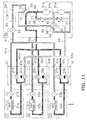
- the actuators (valves) in the refrigerant circuit of the air conditioner are switched to the state shown in FIG. 11 .
- the high-pressure refrigerant discharged from the high-stage compressor 51c flows from the first four-way switching valve 55 to the second refrigerant connection pipe 42 and then flows from the branch units 31, 32, and 33 to the usage-side units 21, 22, and 23.
- the branch units 31, 32, and 33 the first branch unit switching valves 31a, 32a, and 33a are opened and the second branch unit switching valves 31b, 32b, and 33b are closed, and the usage-side heat exchangers 21a, 22a, and 23a are made to function as radiators of the refrigerant.
- the heat source-side expansion valve 54 has its opening degree adjusted so that it reduces the pressure of the refrigerant.
- the usage-side expansion valves 21b, 22b, and 23b have their opening degrees adjusted in accordance with the heating loads of the usage-side units 21,22, and 23.
- the actuators are controlled in such a way that some of the usage-side heat exchangers 21a, 22a, and 23a function as evaporators and some of the others (or all of the others) function as radiators.
- the heat source-side heat exchanger 53 of the heat source-side unit 50 functions as a radiator or an evaporator in accordance with the balance between the cooling loads and the heating loads of the usage-side units 21, 22, and 23.
- the heat source-side expansion valve 54 has its opening degree adjusted so that as much as possible it does not reduce the pressure of the refrigerant, and in a case where the heat source-side heat exchanger 53 functions as an evaporator, the heat source-side expansion valve 54 has its opening degree adjusted so that it reduces the pressure of the refrigerant.
- the branch units 31, 32, and 33 the first branch unit switching valves 31a, 32a, and 33a corresponding to the usage-side units 21, 22, and 23 made to function as evaporators are closed and the second branch unit switching valves 31b, 32b, and 33b corresponding to the usage-side units 21, 22, and 23 made to function as evaporators are opened.
- the first branch unit switching valves 31a, 32a, and 33a corresponding to the usage-side units 21, 22, and 23 made to function as radiators are opened and the second branch unit switching valves 31b, 32b, and 33b corresponding to the usage-side units 21, 22, and 23 made to function as radiators are closed.
- the controller 60 has, as one of the mixed heating and cooling operating modes 60c, an intermediate pressure utilization operating mode.
- the controller 60 controls the two four-way switching valves 55 and 56 so that the intermediate-pressure refrigerant discharged from the low-stage compressor 51a and flowing in the intermediate pressure pipe 51b flows directly to the heat source-side heat exchanger 53 or any one or a plurality of the usage-side heat exchangers 21a, 22a, and 23a.
- the refrigerant circuit of the air conditioner shown in FIG. 7 represents a cooling-oriented intermediate pressure utilization operating mode when the outside air temperature is high and in which the first and third usage-side heat exchangers 21a and 23a are made to function as evaporators and the second usage-side heat exchanger 22a is made to function as a radiator.
- this mode hereinafter called a first mixed operating mode
- the four-way switching valves 55 and 56 are controlled so that the intermediate-pressure refrigerant flowing in the intermediate pressure pipe 51b heads directly to the second usage-side heat exchanger 22a.
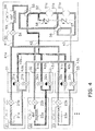
- the refrigerant circuit of the air conditioner shown in FIG. 4 represents a cooling-oriented intermediate pressure utilization operating mode when the outside air temperature is low (or moderate) and in which the first and third usage-side heat exchangers 21a and 23a are made to function as evaporators and the second usage-side heat exchanger 22a is made to function as a radiator.
- this mode hereinafter called a second mixed operating mode
- the four-way switching valves 55 and 56 are controlled so that the intermediate-pressure refrigerant flowing in the intermediate pressure pipe 51b heads directly to the heat source-side heat exchanger 53.
- the controller 60 has the mutually different first mixed operating mode and second mixed operating mode as the same cooling-oriented intermediate pressure utilization operating mode in which the first and third usage-side heat exchangers 21a and 23a are made to function as evaporators and the second usage-side heat exchanger 22a is made to function as a radiator.
- the first mixed operating mode the outside air temperature is high and the loads of the first and third usage-side units 21 and 23 are also large, so the controller 60 delivers the high-pressure refrigerant to the heat source-side heat exchanger 53 and delivers the intermediate-pressure refrigerant to the second usage-side heat exchanger 22a.
- the controller 60 delivers the intermediate-pressure refrigerant to the heat source-side heat exchanger 53 and delivers the high-pressure refrigerant to the second usage-side heat exchanger 22a.
- the controller 60 When moving from the constant cooling operating mode 60a shown in FIG 1 to the mixed heating and cooling operating mode 60c shown in FIG. 4 in accompaniment with the setting of the usage-side unit 22 having switched from cooling to heating, the controller 60 causes the refrigerant circuit to transition through the state shown in FIG. 3 .
- the controller 60 reduces the rotational speed of the high-stage compressor 51c and switches the state of the first four-way switching valve 55 after the pressure difference around the first four-way switching valve 55 becomes smaller. Then, after arriving at the state of the refrigerant circuit shown in FIG.
- the controller 60 gradually increases the rotational speed of the high-stage compressor 51 c and delivers the refrigerant discharged from the high-stage compressor 51c to the usage-side heat exchanger 22a of the usage-side unit 22. Meanwhile, as described above, the intermediate-pressure refrigerant discharged from the low-stage compressor 51a and flowing in the intermediate pressure pipe 51b is delivered to the heat source-side heat exchanger 53.
- the controller 60 changes the rotational speed of the heat source-side fan 59 of the heat source-side unit 50 in accordance with the value of the outside air temperature detected by the outside air temperature sensor 65. Specifically, when the outside air temperature has become lower, the controller 60 performs fan control that reduces the rotational speed of the heat source-side fan 59 and raises the pressure of the intermediate-pressure refrigerant.
- the controller 60 When moving from the cooling-oriented mixed heating and cooling operating mode 60c when the outside air temperature is low (or moderate) shown in FIG. 4 to the heating-oriented mixed heating and cooling operating mode 60c shown in FIG. 6 in accompaniment with the setting of the usage-side unit 23 having switched from cooling to heating, the controller 60 causes the refrigerant circuit to transition through the state shown in FIG. 5 .
- the controller 60 closes the usage-side expansion valve 23b of the usage-side unit 23 and the heat source-side expansion valve 54 of the heat source-side unit 50 to create a state in which the refrigerant does not flow in the usage-side heat exchanger 23 a and the heat source-side heat exchanger 53, gradually stops the low-stage compressor 51a, and switches the state of the second four-way switching valve 56 after the pressure difference around the second four-way switching valve 56 becomes smaller. Thereafter, in the state of the refrigerant circuit in the heating-oriented mixed heating and cooling operating mode 60c when the outside air temperature is low shown in FIG 6 , the low-stage compressor 51a and the high-stage compressor 51c are driven. In the mixed heating and cooling operating mode 60c shown in FIG.
- the high-pressure refrigerant discharged from the high-stage compressor 51 c flows directly to the usage-side heat exchangers 22a and 23a functioning as radiators, and the refrigerant condensed in the usage-side heat exchangers 22a and 23a travels through the first refrigerant connection pipe 41 and separates and flows into the usage-side heat exchanger 21a, functioning as an evaporator, of the first usage-side unit 21 and the heat source-side heat exchanger 53.
- the refrigerant evaporated in the heat source-side heat exchanger 53 is sucked into the low-stage compressor 51a while the refrigerant evaporated in the usage-side heat exchanger 21 a travels through the third refrigerant connection pipe 43 and the intermediate pressure pipe 51b and is sucked into the high-stage compressor 51 c.
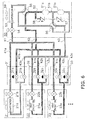
- the controller 60 When moving from the cooling-oriented mixed heating and cooling operating mode 60c when the outside air temperature is high shown in FIG 7 to the heating-oriented mixed heating and cooling operating mode 60c when the outside air temperature is high ( FIG. 9 ) in accompaniment with the setting of the usage-side unit 23 having switched from cooling to heating, the controller 60 causes the refrigerant circuit to transition through the state shown in FIG. 8 .
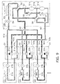
- the controller 60 closes the usage-side expansion valve 23b of the usage-side unit 23 and the heat source-side expansion valve 54 of the heat source-side unit 50 to create a state in which the refrigerant does not flow in the usage-side heat exchanger 23a and the heat source-side heat exchanger 53, gradually stops the high-stage compressor 51c, and switches the state of the first four-way switching valve 55 after the pressure difference around the first four-way switching valve 55 becomes smaller. Thereafter, in the state of the refrigerant circuit in the heating-oriented mixed heating and cooling operating mode 60c when the outside air temperature is high or moderate shown in FIG. 9 , the low-stage compressor 51a and the high-stage compressor 51c are driven. In the mixed heating and cooling operating mode 60c shown in FIG.
- the high-pressure refrigerant discharged from the high-stage compressor 51c flows directly to the usage-side heat exchangers 22a and 23 a functioning as radiators, and the refrigerant condensed in those usage-side heat exchangers 22a and 23a travels through the first refrigerant connection pipe 41 and separates and flows into the usage-side heat exchanger 21 a, functioning as an evaporator, of the first usage-side unit 21 and the heat source-side heat exchanger 53.
- the refrigerant evaporated in the usage-side heat exchanger 21a travels through the third refrigerant connection pipe 43 and is sucked into the low-stage compressor 51a while the refrigerant evaporated in the heat source-side heat exchanger 53 travels through both four-way switching valves 55 and 56 and the intermediate pressure pipe 51b and is sucked into the high-stage compressor 51c.
- the controller 60 performs control that reduces the rotational speed of the heat source-side fan 59 of the heat source-side unit 50 and lowers the pressure of the intermediate-pressure refrigerant.
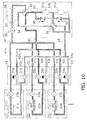
- the controller 60 When moving from the heating-oriented mixed heating and cooling operating mode 60c when the outside air temperature is high shown in FIG 9 to the constant heating operating mode 60b ( FIG. 11 ) in which all of the usage-side units 21, 22, and 23 perform heating, the controller 60 causes the refrigerant circuit to transition through the state shown in FIG. 10 .
- the controller 60 gradually stops the low-stage compressor 51a and switches the state of the second four-way switching valve 56 after the pressure difference around the second four-way switching valve 56 becomes smaller.
- the controller 60 opens the first branch unit switching valve 31a and closes the second branch unit switching valve 31b to cause the high-pressure refrigerant to flow to all of the usage-side heat exchangers 21 a, 22a, and 23a.
- the refrigerant evaporated in the heat source-side heat exchanger 53 is sucked into the low-stage compressor 51a as a result of the state of the second four-way switching valve 56 having switched.
- the controller 60 When moving from the cooling-oriented mixed heating and cooling operating mode 60c when the outside air temperature is high shown in FIG 7 to the cooling-oriented mixed heating and cooling operating mode 60c when the outside air temperature is low (or moderate) shown in FIG 4 after the outside air temperature becomes lower, the controller 60 causes the refrigerant circuit to transition through the state shown in FIG. 12 .
- the controller 60 stops the high-stage compressor 51 c at the point in time when the high/low differential pressure has become unable to be ensured. Then, the controller 60 switches the state of the first four-way switching valve 55 after the pressure difference around the first four-way switching valve 55 becomes smaller.
- the air conditioner switches from a state in which the intermediate-pressure refrigerant discharged from the low-stage compressor 51a and flowing in the intermediate pressure pipe 51 b flows to the usage-side heat exchanger 22a to a state in which the intermediate-pressure refrigerant flows to the heat source-side heat exchanger 53.
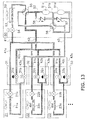
- the controller 60 When moving from the heating-oriented mixed heating and cooling operating mode 60c when the outside air temperature is high shown in FIG. 9 to the heating-oriented mixed heating and cooling operating mode 60c when the outside air temperature is low shown in FIG. 6 , the controller 60 causes the refrigerant circuit to transition through the state shown in FIG. 13 .
- the controller 60 stops the low-stage compressor 51a at the point in time when the high/low differential pressure has become unable to be ensured. Then, the controller 60 switches the state of the second four-way switching valve 56 after the pressure difference around the second four-way switching valve 56 becomes smaller. Because of this switch in the state of the second four-way switching valve 56, as shown in FIG.
- the refrigerant evaporated in the usage-side heat exchanger 21 a flows into the intermediate pressure pipe 51 b and is sucked into the high-stage compressor 51 c. At this time, the refrigerant evaporated in the heat source-side heat exchanger 53 is sucked into the low-stage compressor 51a.
- This air conditioner employs a configuration where the low-stage compressor 51a and the high-stage compressor 51 c are connected to each other in series.
- the air conditioner configures a refrigerant circuit and performs control so that the intermediate-pressure refrigerant discharged from the low-stage compressor 51a and flowing in the intermediate pressure pipe 51b flows to the heat source-side heat exchanger 53 in the first state shown in FIG 4 and flows to the usage-side heat exchanger 22a in the second state shown in FIG. 7 .
- the four-way switching valves 55 and 56 are switched to the first state shown in FIG.
- the four-way switching valves 55 and 56 are switched to the second state shown in FIG. 7 to deliver the intermediate-pressure refrigerant to the second usage-side heat exchanger 22a so that the operating efficiency of the air conditioner can be improved.
- the controller 60 of the air conditioner has, as one of the mixed heating and cooling operating modes 60c, the intermediate pressure utilization operating mode in which the first usage-side heat exchanger 21 a functions as an evaporator and the second usage-side heat exchanger 22a functions as a radiator (see FIG. 4 and FIG. 7 ).
- the controller 60 controls the four-way switching valves 55 and 56, which are switching mechanisms, so that the intermediate-pressure refrigerant discharged from the low-stage compressor 51a and flowing in the intermediate pressure pipe 51b flows directly to the heat source-side heat exchanger 53 or the usage-side heat exchanger 22a.
- the controller 60 of the air conditioner has, as the mixed heating and cooling operating mode 60c, the first mixed operating mode shown in FIG. 7 and the second mixed operating mode shown in FIG. 4 . Additionally, the controller 60 controls the four-way switching valves 55 and 56 so that in the first mixed operating mode the intermediate-pressure refrigerant flows to the second usage-side heat exchanger 22a and in the second mixed operating mode the high-pressure refrigerant flows to the second usage-side heat exchanger 22a.
- this air conditioner it becomes possible to select to have the high-pressure refrigerant flow to the usage-side heat exchanger 22a and select to have the intermediate-pressure refrigerant flow to the usage-side heat exchanger 22a, and in a case where the heat load of the space in which the usage-side unit 22 is installed is small, the intermediate-pressure refrigerant is used so that the operating efficiency of the air conditioner can be improved.
- the controller 60 of the air conditioner causes the heating operation to be performed in the second usage-side unit 22 by causing the high-pressure refrigerant discharged from the high-stage compressor 51c to flow to the heat source-side heat exchanger 53 and radiate heat and causing some of the intermediate-pressure refrigerant discharged from the low-stage compressor 51a to flow to the second usage-side heat exchanger 22a and radiate heat.
- the refrigerant that has radiated heat and condensed in the heat source-side heat exchanger 53 and the usage-side heat exchanger 22a flows to the first and third usage-side heat exchangers 21a and 23a and evaporates.
- This first mixed operating mode is selected by the controller 60 in a case where the outside air temperature is high and the heat load of heating in the second usage-side unit 22 is small, and the operating efficiency of the air conditioner is improved.
- the controller 60 of the air conditioner controls the four-way switching valves 55 and 56 so that the high-pressure refrigerant discharged from the high-stage compressor 51c flows to the second usage-side heat exchanger 22a and some of the intermediate-pressure refrigerant discharged from the low-stage compressor 51a flows to the heat source-side heat exchanger 53, and in accordance with the outside air temperature the controller 60 changes the rotational speed of the heat source-side fan 59 and adjusts the pressure of the intermediate-pressure refrigerant. Specifically, when the outside air temperature has become lower, the controller 60 performs fan control that reduces the rotational speed of the heat source-side fan 59 and raises the pressure of the intermediate-pressure refrigerant. Because of this, the operating efficiency of the air conditioner is improved.
- the controller 60 of the air conditioner causes the refrigerant circuit to transition through the state shown in FIG. 12 when switching from the first mixed operating mode shown in FIG. 7 to the second mixed operating mode shown in FIG 4 .
- the controller 60 temporarily stops the high-stage compressor 51 c and switches the state of the first four-way switching valve 55 after the pressure difference around the first four-way switching valve 55 becomes smaller.
- the controller 60 switches the state after the surrounding pressure difference becomes smaller, the state of the four-way switching valve 55 can be reliably switched.
- Patent Document 1 JP-A No. 2003-130492
Landscapes
- Engineering & Computer Science (AREA)
- Physics & Mathematics (AREA)
- Mechanical Engineering (AREA)
- Thermal Sciences (AREA)
- General Engineering & Computer Science (AREA)
- Compression-Type Refrigeration Machines With Reversible Cycles (AREA)
- Air Conditioning Control Device (AREA)
Abstract
Description
- The present invention relates to a refrigeration system.
- As a conventional refrigeration system, there is an air conditioning system equipped with a heat source-side unit and a plurality of usage-side units and capable of performing a concurrent heating and cooling operation. For example, patent document 1 (
JP-A No. 2003-130492 - In the conventional refrigeration system capable of performing the concurrent heating and cooling operation, in a case where there is just one compressor, the situation becomes such that the pressure values of the high pressure and the low pressure become one, and depending on the outside air temperature the refrigeration system is operated with an excessive high/low differential pressure. Operating with a greater than necessary high/low differential pressure in this way runs counter to the demand to conserve energy.
- To address this, the air conditioner disclosed in patent document 1 (
JP-A No. 2003-130492 - However, what is needed is a refrigeration system having still another refrigeration cycle configuration and whose operating efficiency is good.
- It is a problem of the present invention to provide a refrigeration system with improved operating efficiency.
- A refrigeration system pertaining to a first aspect of the present invention comprises a heat source-side unit, a first usage-side unit, a second usage-side unit, and a switching mechanism. The heat source-side unit has a compression mechanism including a low-stage compressor and a high-stage compressor, a heat source-side heat exchanger, and a heat source-side expansion mechanism. The first usage-side unit has a first usage-side heat exchanger and a first usage-side expansion mechanism. The second usage-side unit has a second usage-side heat exchanger and a second usage-side expansion mechanism. The switching mechanism switches the path of refrigerant flowing from the compression mechanism to the heat source-side heat exchanger, the first usage-side heat exchanger, and the second usage-side heat exchanger. Additionally, the low-stage compressor and the high-stage compressor are connected to each other in series via an intermediate pressure pipe. The switching mechanism switches between a first state and a second state. The first state is a state in which intermediate-pressure refrigerant discharged from the low-stage compressor and flowing in the intermediate pressure pipe flows to the heat source-side heat exchanger. The second state is a state in which the intermediate-pressure refrigerant flows to the first usage-side heat exchanger or the second usage-side heat exchanger.
- Here, the refrigeration system employs a configuration where the low-stage compressor and the high-stage compressor are connected to each other in series, and the refrigeration system configures a refrigerant circuit so that the intermediate-pressure refrigerant discharged from the low-stage compressor and flowing in the intermediate pressure pipe flows to the heat source-side heat exchanger in the first state and flows to the first usage-side heat exchanger or the second usage-side heat exchanger in the second state. According to this refrigeration system pertaining to the present invention, for example, in a case where the outside air temperature is low and the high-pressure refrigerant is not needed in the heat source-side heat exchanger, the switching mechanism is switched to the first state so that the operating efficiency can be improved. Furthermore, for example, in a case where, when the outside air temperature is high, it is necessary to make the first usage-side heat exchanger function as an evaporator and make the second usage-side heat exchanger function as a radiator with respect to a small heat load, the switching mechanism is switched to the second state to deliver the intermediate-pressure refrigerant to the second usage-side heat exchanger so that the operating efficiency of the refrigeration system can be improved.
- A refrigeration system pertaining to a second aspect of the present invention is the refrigeration system pertaining to the first aspect, further comprising a controller that controls the switching mechanism. The controller has an intermediate pressure utilization operating mode in which the first usage-side heat exchanger functions as an evaporator and the second usage-side heat exchanger functions as a radiator. In the intermediate pressure utilization operating mode the controller controls the switching mechanism so that the intermediate-pressure refrigerant discharged from the low-stage compressor and flowing in the intermediate pressure pipe flows directly to the heat source-side heat exchanger, the first usage-side heat exchanger, or the second usage-side heat exchanger.
- Here, the intermediate pressure utilization operating mode is disposed as an operating mode, so it becomes possible to improve the operating efficiency of the refrigeration system by actively utilizing the intermediate-pressure refrigerant and not just the high-pressure refrigerant discharged from the high-stage compressor that has conventionally been utilized.
- A refrigeration system pertaining to a third aspect of the present invention is the refrigeration system pertaining to the first aspect, further comprising a controller that controls the switching mechanism. The controller has a first mixed operating mode and a second mixed operating mode. In the first mixed operating mode and the second mixed operating mode, the first usage-side heat exchanger functions as an evaporator and the second usage-side heat exchanger functions as a radiator. In the first mixed operating mode the controller controls the switching mechanism so that the intermediate-pressure refrigerant discharged from the low-stage compressor and flowing in the intermediate pressure pipe flows to the second usage-side heat exchanger. Furthermore, in the second mixed operating mode the controller controls the switching mechanism so that high-pressure refrigerant discharged from the high-stage compressor flows to the second usage-side heat exchanger.
- Here, the first mixed operating mode and the second mixed operating mode are disposed as operating modes in which the usage-side unit whose usage-side heat exchanger functions as an evaporator and the usage-side unit whose usage-side heat exchanger functions as a radiator are mixed. Additionally, in the first mixed operating mode the intermediate-pressure refrigerant flows to the second usage-side heat exchanger, and in the second mixed operating mode the high-pressure refrigerant flows to the second usage-side heat exchanger. In this way, in this refrigeration system, it becomes possible to select to have the intermediate-pressure refrigerant flow to the usage-side heat exchangers in addition to selecting to have the high-pressure refrigerant flow to the usage-side heat exchangers, and in a case where the heat load of the space in which the usage-side unit is installed is small, the intermediate-pressure refrigerant is used so that the operating efficiency of the refrigeration system overall can be improved.
- A refrigeration system pertaining to a fourth aspect of the present invention is the refrigeration system pertaining to the third aspect, wherein in the first mixed operating mode the controller controls the switching mechanism so that the intermediate-pressure refrigerant flows to the second usage-side heat exchanger and the high-pressure refrigerant discharged from the high-stage compressor flows to the heat source-side heat exchanger.
- In the first mixed operating mode of this refrigeration system, the controller causes heating to be performed by the second usage-side unit by causing the high-pressure refrigerant to flow to the heat source-side heat exchanger and radiate heat and causing the intermediate-pressure refrigerant to flow to the second usage-side heat exchanger and radiate heat. The refrigerant after having radiated heat in these heat exchangers flows to the first usage-side heat exchanger and evaporates. By configuring the control logic to select this first mixed operating mode in a case where, for example, the outside air temperature is high and the heat load of heating in the second usage-side unit is small, the operating efficiency of the refrigeration system is improved.
- A refrigeration system pertaining to a fifth aspect of the present invention is the refrigeration system pertaining to the third aspect or the fourth aspect, wherein the heat source-side unit further has a heat source-side fan for delivering outside air to the heat source-side heat exchanger and an outside air temperature sensor that detects the outside air temperature. Additionally, in the second mixed operating mode the controller controls the switching mechanism so that the high-pressure refrigerant flows to the second usage-side heat exchanger and the intermediate-pressure refrigerant flows to the heat source-side heat exchanger, and in accordance with the outside air temperature the controller changes the rotational speed of the heat source-side fan and adjusts the pressure of the intermediate-pressure refrigerant.
- Here, in a case where, for example, the outside air temperature is not high, the controller causes the intermediate-pressure refrigerant to flow to the heat source-side heat exchanger when the first usage-side heat exchanger functioning as an evaporator needs low-pressure refrigerant and the second usage-side heat exchanger functioning as a radiator needs high-pressure refrigerant. Because of this, the operating efficiency of the refrigeration system can be kept high without having to needlessly lower the pressure of the high-pressure refrigerant and reduce the operating efficiency. Moreover, in order for refrigerant having a pressure conforming to the outside air temperature to flow in the heat source-side heat exchanger, here, the controller changes the rotational speed of the heat source-side fan in accordance with the outside air temperature. By performing this kind of control, the operating efficiency can be improved even more. Specifically, for example, when the outside air temperature has become lower, it is conceivable for the controller to perform control in which it reduces the rotational speed of the heat source-side fan and raises the pressure of the intermediate-pressure refrigerant.
- A refrigeration system pertaining to a sixth aspect of the present invention is the refrigeration system pertaining to any of the third aspect to the fifth aspect, wherein the controller temporarily stops the low-stage compressor or the high-stage compressor when switching from the first mixed operating mode to the second mixed operating mode and, after the path of the refrigerant has been switched by the switching mechanism, returns to a state in which both the low-stage compressor and the high-stage compressor operate.
- When switching from the first mixed operating mode in which the intermediate-pressure refrigerant flows to the second usage-side heat exchanger to the second mixed operating mode in which the high-pressure refrigerant flows to the second usage-side heat exchanger, the state of the switching mechanism changes and noise is produced, but here, by temporarily stopping the low-stage compressor or the high-stage compressor, the magnitude of the noise that is produced can be controlled. Furthermore, by switching the state after the pressure difference around the switching mechanism becomes smaller, the state of the switching mechanism switches reliably.
- According to the refrigeration system pertaining to the present invention, it becomes possible to cause the intermediate-pressure refrigerant to flow to the heat source-side heat exchanger and to cause the intermediate-pressure refrigerant to flow to the usage-side heat exchangers, and refrigerant having an appropriate pressure according to the heat loads and the outside air temperature can be caused to flow to each heat exchanger, so the operating efficiency is improved.
-
-
FIG 1 is a refrigerant circuit diagram showing a constant cooling state of an air conditioner that is a refrigeration system pertaining to an embodiment of the present invention. -
FIG. 2 is a control block diagram of the air conditioner. -
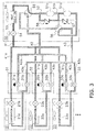
FIG. 3 is a refrigerant circuit diagram showing a state in which the air conditioner is transitioning from the cooling state to a mixed heating and cooling/cooling-oriented state (outside air temperature is moderate/low). -
FIG. 4 is a refrigerant circuit diagram showing the mixed heating and cooling/cooling-oriented state of the air conditioner (outside air temperature is moderate/low). -
FIG. 5 is a refrigerant circuit diagram showing a state in which the air conditioner is transitioning from the mixed heating and cooling/cooling-oriented state (outside air temperature is moderate/low) to a mixed heating and cooling/heating-oriented state (outside air temperature is low). -
FIG. 6 is a refrigerant circuit diagram showing the mixed heating and cooling/heating-oriented state of the air conditioner (outside air temperature is low). -
FIG 7 is a refrigerant circuit diagram showing the mixed heating and cooling/cooling-oriented state of the air conditioner (outside air temperature is high). -
FIG. 8 is a refrigerant circuit diagram showing a state in which the air conditioner is transitioning from the mixed heating and cooling/cooling-oriented state (outside air temperature is high) to the mixed heating and cooling/heating-oriented state (outside air temperature is high). -
FIG 9 is a refrigerant circuit diagram showing the mixed heating and cooling/heating-oriented state of the air conditioner (outside air temperature is high). -
FIG. 10 is a refrigerant circuit diagram showing a state in which the air conditioner is transitioning from the mixed heating and cooling/heating-oriented state (outside air temperature is high) to a constant heating state. -
FIG. 11 is a refrigerant circuit diagram showing the constant heating state of the air conditioner. -
FIG. 12 is a refrigerant circuit diagram showing a state in which the air conditioner is transitioning from the mixed heating and cooling/cooling-oriented state (outside air temperature is high) to the mixed heating and cooling/cooling-oriented state (outside air temperature is moderate/low). -
FIG. 13 is a refrigerant circuit diagram showing a state in which the air conditioner is transitioning from the mixed heating and cooling/heating-oriented state (outside air temperature is high/moderate) to the mixed heating and cooling/heating-oriented state (outside air temperature is moderate low). - An air conditioner serving as a refrigeration system pertaining to an embodiment of the present invention will be described below on the basis of the drawings.
-
FIG. 1 is a schematic configuration diagram of a refrigerant circuit of the air conditioner. The air conditioner is a system used to cool and heat the interior of a building, for example, by performing vapor compression refrigeration cycle operations. - The air conditioner is mainly equipped with one heat source-
side unit 50, a plurality of (here, three) usage-side units branch units refrigerant connection pipes side unit 50, the usage-side units branch units refrigerant connection pipes refrigerant connection pipe 41 extends from the heat source-side unit 50 to the usage-side units refrigerant connection pipe 41a, a secondrefrigerant connection pipe 41b, and a thirdrefrigerant connection pipe 41 c. Therefrigerant connection pipe 42 extends from the heat source-side unit 50 to the usage-side units refrigerant connection pipe 42a, a secondrefrigerant connection pipe 42b, and a thirdrefrigerant connection pipe 42c. Therefrigerant connection pipe 43 extends from the heat source-side unit 50 to the usage-side units refrigerant connection pipe 43b, and a thirdrefrigerant connection pipe 43c. Additionally, the refrigerant circuit is charged with R32 refrigerant. - Furthermore, as shown in
FIG. 2 , the air conditioner is controlled by acontroller 60 configured by the electrical interconnection of a heat source-side unit controller in the heat source-side unit 50 and usage-side unit controllers in the usage-side units side unit 50 and the usage-side units controller 60. Thecontroller 60 sends activation instructions to actuators, shown inFIG. 2 , of the heat source-side unit 50, the usage-side units branch units controller 60 will be described in detail later. - The usage-
side units side units side unit 50 via therefrigerant connection pipes branch units - Next, the configuration of the usage-
side units side unit 21 has a first usage-side heat exchanger 21a and a first usage-side expansion valve 21 b. The second usage-side unit 22 has a second usage-side heat exchanger 22a and a second usage-side expansion valve 22b. The third usage-side unit 23 has a third usage-side heat exchanger 23a and a third usage-side expansion valve 23b. The usage-side heat exchangers - It should be noted that although an air conditioner having three usage-side units is described here, the present invention can also be applied to a case where a greater number of usage-side units are connected to one heat source-side unit to configure one refrigerant circuit.
- The
branch units side units refrigerant connection pipes side units side unit 50, and configure part of the refrigerant circuit. Thebranch units side units - The
branch units unit switching valves unit switching valves unit switching valves refrigerant connection pipe 42 and the usage-side heat exchangers unit switching valves refrigerant connection pipe 43 and the usage-side heat exchangers - The heat source-
side unit 50 is, for example, installed on the roof of the building or in the area around the building, is connected to the usage-side units refrigerant connection pipes branch units - The heat source-
side unit 50 mainly has acompression mechanism 51 including a low-stage compressor 51a and a high-stage compressor 51c, a heat source-side heat exchanger 53, a heat source-side expansion valve 54, two four-way switching valves side fan 59. - As shown in
FIG 1 , the low-stage compressor 51a and the high-stage compressor 51c are connected to each other in series via anintermediate pressure pipe 51b. The low-stage compressor 51a and the high-stage compressor 51c are rotary-type or scroll-type positive-displacement compressors, and suck in the refrigerant and compress and discharge the sucked-in refrigerant. Here, the refrigerant discharged from the low-stage compressor 51a to theintermediate pressure pipe 51b will be called intermediate-pressure refrigerant, and the refrigerant discharged from the high-stage compressor 51c to the first four-way switching valve 55 side will be called high-pressure refrigerant. - It should be noted that a bypass circuit is disposed in the low-
stage compressor 51a and in the high-stage compressor 51c. Acheck valve 57 is placed in the bypass circuit of the low-stage compressor 51a, and acheck valve 58 is placed in the bypass circuit of the high-stage compressor 51 c. The refrigerant flows in these bypass circuits when one of the low-stage compressor 51a and the high-stage compressor 51c has stopped. For example, in the state shown inFIG. 5 in which the low-stage compressor 51a is stopped, the refrigerant travels through thecheck valve 57, and in the state shown inFIG. 12 in which the high-stage compressor 51c is stopped, the refrigerant travels through thecheck valve 58. - The heat source-
side heat exchanger 53 is a heat exchanger that functions as a radiator or an evaporator of the refrigerant by performing heat exchange between the refrigerant and outdoor air (outside air). - The heat source-
side expansion valve 54 is an electrically powered expansion valve that reduces the pressure of the refrigerant flowing through the heat source-side unit 50, and is disposed between the heat source-side heat exchanger 53 and the firstrefrigerant connection pipe 41. - The first four-
way switching valve 55 is an electrically powered valve capable of switching between a heat source-side radiation state that makes the heat source-side heat exchanger 53 function as a radiator of the refrigerant and a heat source-side evaporation state that makes the heat source-side heat exchanger 53 function as an evaporator of the refrigerant. Afirst port 71 of the four-way switching valve 55 is connected to the discharge side of the high-stage compressor 51 c, asecond port 72 is connected to the gas side of the heat source-side heat exchanger 53, athird port 73 is connected to athird port 83 of the second four-way switching valve 56, and afourth port 74 is connected to the secondrefrigerant connection pipe 42. The first four-way switching valve 55 is capable of switching between a state in which it interconnects thefirst port 71 and thesecond port 72 and also interconnects thethird port 73 and the fourth port 74 (corresponding to the heat source-side radiation state; for example, see the state of the four-way switching valve 55 inFIG. 1 ) and a state in which it interconnects thesecond port 72 and thethird port 73 and also interconnects thefirst port 71 and the fourth port 74 (radiating heat to heat source-side low-temperature outside air, or corresponding to the heat source-side evaporation state; for example, see the state of the four-way switching valve 55 inFIG. 4 andFIG. 11 ). - The second four-
way switching valve 56 is an electrically powered valve capable of switching between a state in which it places theintermediate pressure pipe 51b, which connects the low-stage compressor 51a and the high-stage compressor 51 c to each other, in communication with the thirdrefrigerant connection pipe 43 and a state in which it places theintermediate pressure pipe 51b in communication with thethird port 73 of the first four-way switching valve 55. Afirst port 81 of the four-way switching valve 56 is connected to the thirdrefrigerant connection pipe 43. Asecond port 82 is connected to theintermediate pressure pipe 51b. Athird port 83 is connected to thethird port 73 of the first four-way switching valve 55 A fourth port 84 is connected to the suction side of the low-stage compressor 51a. - The two four-
way switching valves FIG. 4 , for example, the intermediate-pressure refrigerant discharged from the low-stage compressor 51a and flowing in theintermediate pressure pipe 51 b flows to the heat source-side heat exchanger 53. The second state is a state in which, as shown inFIG. 7 , for example, the intermediate-pressure refrigerant discharged to theintermediate pressure pipe 51 b flows to any one or a plurality of the usage-side heat exchangers - It should be noted that the switching mechanism configured from the two four-
way switching valves - As operating modes of the air conditioner pertaining to the present embodiment, the
controller 60 has a constantcooling operating mode 60a that cools all of the usage-side units heating operating mode 60b that heats all of the usage-side units side units cooling operating mode 60c. In the mixed heating andcooling operating mode 60c, some of the usage-side units side units - In the constant
cooling operating mode 60a that cools all of the usage-side units FIG. 1 . The heat source-side heat exchanger 53 into which the high-pressure refrigerant flows functions as a radiator of the refrigerant, and the heat source-side expansion valve 54 has its opening degree adjusted (e.g., so that it is completely open) so that as much as possible it does not reduce the pressure of the refrigerant. In thebranch units unit switching valves unit switching valves side heat exchangers side heat exchangers refrigerant connection pipe 43 and the second four-way switching valve 56 and is sucked into the low-stage compressor 51 a. It should be noted that the usage-side expansion valves side units - In the constant
heating operating mode 60b that heats all of the usage-side units FIG. 11 . The high-pressure refrigerant discharged from the high-stage compressor 51c flows from the first four-way switching valve 55 to the secondrefrigerant connection pipe 42 and then flows from thebranch units side units branch units unit switching valves unit switching valves side heat exchangers side heat exchangers side expansion valve 54 to the heat source-side heat exchanger 53, and the refrigerant evaporated there is sucked via the first and second four-way switching valves stage compressor 51a. The heat source-side expansion valve 54 has its opening degree adjusted so that it reduces the pressure of the refrigerant. The usage-side expansion valves side units - In the mixed heating and
cooling operating mode 60c in which some of the usage-side units side units side heat exchangers side heat exchanger 53 of the heat source-side unit 50 functions as a radiator or an evaporator in accordance with the balance between the cooling loads and the heating loads of the usage-side units side heat exchanger 53 functions as a radiator, the heat source-side expansion valve 54 has its opening degree adjusted so that as much as possible it does not reduce the pressure of the refrigerant, and in a case where the heat source-side heat exchanger 53 functions as an evaporator, the heat source-side expansion valve 54 has its opening degree adjusted so that it reduces the pressure of the refrigerant. In thebranch units unit switching valves side units unit switching valves side units unit switching valves side units unit switching valves side units - The
controller 60 has, as one of the mixed heating andcooling operating modes 60c, an intermediate pressure utilization operating mode. In the intermediate pressure utilization operating mode thecontroller 60 controls the two four-way switching valves stage compressor 51a and flowing in theintermediate pressure pipe 51b flows directly to the heat source-side heat exchanger 53 or any one or a plurality of the usage-side heat exchangers - The refrigerant circuit of the air conditioner shown in
FIG. 7 represents a cooling-oriented intermediate pressure utilization operating mode when the outside air temperature is high and in which the first and third usage-side heat exchangers side heat exchanger 22a is made to function as a radiator. In this mode (hereinafter called a first mixed operating mode), the four-way switching valves intermediate pressure pipe 51b heads directly to the second usage-side heat exchanger 22a. - Furthermore, the refrigerant circuit of the air conditioner shown in
FIG. 4 represents a cooling-oriented intermediate pressure utilization operating mode when the outside air temperature is low (or moderate) and in which the first and third usage-side heat exchangers side heat exchanger 22a is made to function as a radiator. In this mode (hereinafter called a second mixed operating mode), the four-way switching valves intermediate pressure pipe 51b heads directly to the heat source-side heat exchanger 53. - That is, the
controller 60 has the mutually different first mixed operating mode and second mixed operating mode as the same cooling-oriented intermediate pressure utilization operating mode in which the first and third usage-side heat exchangers side heat exchanger 22a is made to function as a radiator. In the first mixed operating mode, the outside air temperature is high and the loads of the first and third usage-side units controller 60 delivers the high-pressure refrigerant to the heat source-side heat exchanger 53 and delivers the intermediate-pressure refrigerant to the second usage-side heat exchanger 22a. In the second mixed operating mode, the outside air temperature is not high and the loads of the first and third usage-side units controller 60 delivers the intermediate-pressure refrigerant to the heat source-side heat exchanger 53 and delivers the high-pressure refrigerant to the second usage-side heat exchanger 22a. - Next, an example of transitioning from the constant
cooling operating mode 60a to the mixed heating andcooling operating mode 60c, examples of transitioning from the mixed heating andcooling operating mode 60c to other mixed heating andcooling operating modes 60c, and an example of transitioning from the mixed heating andcooling operating mode 60c to the constantheating operating mode 60b will be described. - When moving from the constant
cooling operating mode 60a shown inFIG 1 to the mixed heating andcooling operating mode 60c shown inFIG. 4 in accompaniment with the setting of the usage-side unit 22 having switched from cooling to heating, thecontroller 60 causes the refrigerant circuit to transition through the state shown inFIG. 3 . When the outside air temperature becomes lower and the setting of the usage-side unit 22 switches from cooling to heating, thecontroller 60 reduces the rotational speed of the high-stage compressor 51c and switches the state of the first four-way switching valve 55 after the pressure difference around the first four-way switching valve 55 becomes smaller. Then, after arriving at the state of the refrigerant circuit shown inFIG. 4 , thecontroller 60 gradually increases the rotational speed of the high-stage compressor 51 c and delivers the refrigerant discharged from the high-stage compressor 51c to the usage-side heat exchanger 22a of the usage-side unit 22. Meanwhile, as described above, the intermediate-pressure refrigerant discharged from the low-stage compressor 51a and flowing in theintermediate pressure pipe 51b is delivered to the heat source-side heat exchanger 53. - It should be noted that, in the cooling-oriented mixed heating and
cooling operating mode 60c shown inFIG. 4 , thecontroller 60 changes the rotational speed of the heat source-side fan 59 of the heat source-side unit 50 in accordance with the value of the outside air temperature detected by the outsideair temperature sensor 65. Specifically, when the outside air temperature has become lower, thecontroller 60 performs fan control that reduces the rotational speed of the heat source-side fan 59 and raises the pressure of the intermediate-pressure refrigerant. - When moving from the cooling-oriented mixed heating and
cooling operating mode 60c when the outside air temperature is low (or moderate) shown inFIG. 4 to the heating-oriented mixed heating andcooling operating mode 60c shown inFIG. 6 in accompaniment with the setting of the usage-side unit 23 having switched from cooling to heating, thecontroller 60 causes the refrigerant circuit to transition through the state shown inFIG. 5 . Here, thecontroller 60 closes the usage-side expansion valve 23b of the usage-side unit 23 and the heat source-side expansion valve 54 of the heat source-side unit 50 to create a state in which the refrigerant does not flow in the usage-side heat exchanger 23 a and the heat source-side heat exchanger 53, gradually stops the low-stage compressor 51a, and switches the state of the second four-way switching valve 56 after the pressure difference around the second four-way switching valve 56 becomes smaller. Thereafter, in the state of the refrigerant circuit in the heating-oriented mixed heating andcooling operating mode 60c when the outside air temperature is low shown inFIG 6 , the low-stage compressor 51a and the high-stage compressor 51c are driven. In the mixed heating andcooling operating mode 60c shown inFIG. 6 , the high-pressure refrigerant discharged from the high-stage compressor 51 c flows directly to the usage-side heat exchangers side heat exchangers refrigerant connection pipe 41 and separates and flows into the usage-side heat exchanger 21a, functioning as an evaporator, of the first usage-side unit 21 and the heat source-side heat exchanger 53. Then, as a result of the state of the second four-way switching valve 56 being switched, the refrigerant evaporated in the heat source-side heat exchanger 53 is sucked into the low-stage compressor 51a while the refrigerant evaporated in the usage-side heat exchanger 21 a travels through the thirdrefrigerant connection pipe 43 and theintermediate pressure pipe 51b and is sucked into the high-stage compressor 51 c. - When moving from the cooling-oriented mixed heating and
cooling operating mode 60c when the outside air temperature is high shown inFIG 7 to the heating-oriented mixed heating andcooling operating mode 60c when the outside air temperature is high (FIG. 9 ) in accompaniment with the setting of the usage-side unit 23 having switched from cooling to heating, thecontroller 60 causes the refrigerant circuit to transition through the state shown inFIG. 8 . Here, thecontroller 60 closes the usage-side expansion valve 23b of the usage-side unit 23 and the heat source-side expansion valve 54 of the heat source-side unit 50 to create a state in which the refrigerant does not flow in the usage-side heat exchanger 23a and the heat source-side heat exchanger 53, gradually stops the high-stage compressor 51c, and switches the state of the first four-way switching valve 55 after the pressure difference around the first four-way switching valve 55 becomes smaller. Thereafter, in the state of the refrigerant circuit in the heating-oriented mixed heating andcooling operating mode 60c when the outside air temperature is high or moderate shown inFIG. 9 , the low-stage compressor 51a and the high-stage compressor 51c are driven. In the mixed heating andcooling operating mode 60c shown inFIG. 9 , the high-pressure refrigerant discharged from the high-stage compressor 51c flows directly to the usage-side heat exchangers side heat exchangers refrigerant connection pipe 41 and separates and flows into the usage-side heat exchanger 21 a, functioning as an evaporator, of the first usage-side unit 21 and the heat source-side heat exchanger 53. Then, the refrigerant evaporated in the usage-side heat exchanger 21a travels through the thirdrefrigerant connection pipe 43 and is sucked into the low-stage compressor 51a while the refrigerant evaporated in the heat source-side heat exchanger 53 travels through both four-way switching valves intermediate pressure pipe 51b and is sucked into the high-stage compressor 51c. - It should be noted that when the outside air temperature is high in the heating-oriented mixed heating and
cooling operating mode 60c shown inFIG. 9 , thecontroller 60 performs control that reduces the rotational speed of the heat source-side fan 59 of the heat source-side unit 50 and lowers the pressure of the intermediate-pressure refrigerant. - When moving from the heating-oriented mixed heating and
cooling operating mode 60c when the outside air temperature is high shown inFIG 9 to the constantheating operating mode 60b (FIG. 11 ) in which all of the usage-side units controller 60 causes the refrigerant circuit to transition through the state shown inFIG. 10 . When the setting of the usage-side unit 21 switches from cooling to heating, thecontroller 60 gradually stops the low-stage compressor 51a and switches the state of the second four-way switching valve 56 after the pressure difference around the second four-way switching valve 56 becomes smaller. Then, as shown inFIG 11 , thecontroller 60 opens the first branchunit switching valve 31a and closes the second branchunit switching valve 31b to cause the high-pressure refrigerant to flow to all of the usage-side heat exchangers side heat exchanger 53 is sucked into the low-stage compressor 51a as a result of the state of the second four-way switching valve 56 having switched. - When moving from the cooling-oriented mixed heating and
cooling operating mode 60c when the outside air temperature is high shown inFIG 7 to the cooling-oriented mixed heating andcooling operating mode 60c when the outside air temperature is low (or moderate) shown inFIG 4 after the outside air temperature becomes lower, thecontroller 60 causes the refrigerant circuit to transition through the state shown inFIG. 12 . When the outside air temperature becomes lower, the pressure of the high-pressure refrigerant becomes lower, so thecontroller 60 stops the high-stage compressor 51 c at the point in time when the high/low differential pressure has become unable to be ensured. Then, thecontroller 60 switches the state of the first four-way switching valve 55 after the pressure difference around the first four-way switching valve 55 becomes smaller. Because of this switch in the state of the first four-way switching valve 55, the air conditioner switches from a state in which the intermediate-pressure refrigerant discharged from the low-stage compressor 51a and flowing in theintermediate pressure pipe 51 b flows to the usage-side heat exchanger 22a to a state in which the intermediate-pressure refrigerant flows to the heat source-side heat exchanger 53. - When moving from the heating-oriented mixed heating and
cooling operating mode 60c when the outside air temperature is high shown inFIG. 9 to the heating-oriented mixed heating andcooling operating mode 60c when the outside air temperature is low shown inFIG. 6 , thecontroller 60 causes the refrigerant circuit to transition through the state shown inFIG. 13 . When the pressure of the intermediate-pressure refrigerant becomes lower in accompaniment with the outside air temperature becoming lower, thecontroller 60 stops the low-stage compressor 51a at the point in time when the high/low differential pressure has become unable to be ensured. Then, thecontroller 60 switches the state of the second four-way switching valve 56 after the pressure difference around the second four-way switching valve 56 becomes smaller. Because of this switch in the state of the second four-way switching valve 56, as shown inFIG. 6 , the refrigerant evaporated in the usage-side heat exchanger 21 a flows into theintermediate pressure pipe 51 b and is sucked into the high-stage compressor 51 c. At this time, the refrigerant evaporated in the heat source-side heat exchanger 53 is sucked into the low-stage compressor 51a. - This air conditioner employs a configuration where the low-
stage compressor 51a and the high-stage compressor 51 c are connected to each other in series. In addition, the air conditioner configures a refrigerant circuit and performs control so that the intermediate-pressure refrigerant discharged from the low-stage compressor 51a and flowing in theintermediate pressure pipe 51b flows to the heat source-side heat exchanger 53 in the first state shown inFIG 4 and flows to the usage-side heat exchanger 22a in the second state shown inFIG. 7 . According to this air conditioner, in a case where the outside air temperature is low and the high-pressure refrigerant is not needed in the heat source-side heat exchanger 53, the four-way switching valves FIG. 4 so that the operating efficiency of the air conditioner can be improved. Furthermore, as shown inFIG. 7 , in a case where, when the outside air temperature is high, it is necessary to make the first and third usage-side heat exchangers side heat exchanger 22a function as a radiator with respect to a small heat load, the four-way switching valves FIG. 7 to deliver the intermediate-pressure refrigerant to the second usage-side heat exchanger 22a so that the operating efficiency of the air conditioner can be improved. - The
controller 60 of the air conditioner has, as one of the mixed heating andcooling operating modes 60c, the intermediate pressure utilization operating mode in which the first usage-side heat exchanger 21 a functions as an evaporator and the second usage-side heat exchanger 22a functions as a radiator (seeFIG. 4 andFIG. 7 ). In the intermediate pressure utilization operating mode thecontroller 60 controls the four-way switching valves stage compressor 51a and flowing in theintermediate pressure pipe 51b flows directly to the heat source-side heat exchanger 53 or the usage-side heat exchanger 22a. In this way, by actively utilizing the intermediate-pressure refrigerant and not just the high-pressure refrigerant discharged from the high-stage compressor that has conventionally been used, an operation for lowering the pressure of the high-pressure refrigerant does not have to be needlessly performed, and the operating efficiency of the air conditioner can be improved. - The
controller 60 of the air conditioner has, as the mixed heating andcooling operating mode 60c, the first mixed operating mode shown inFIG. 7 and the second mixed operating mode shown inFIG. 4 . Additionally, thecontroller 60 controls the four-way switching valves side heat exchanger 22a and in the second mixed operating mode the high-pressure refrigerant flows to the second usage-side heat exchanger 22a. In this way, in this air conditioner, it becomes possible to select to have the high-pressure refrigerant flow to the usage-side heat exchanger 22a and select to have the intermediate-pressure refrigerant flow to the usage-side heat exchanger 22a, and in a case where the heat load of the space in which the usage-side unit 22 is installed is small, the intermediate-pressure refrigerant is used so that the operating efficiency of the air conditioner can be improved. - In the first mixed operating mode shown in
FIG. 7 , thecontroller 60 of the air conditioner causes the heating operation to be performed in the second usage-side unit 22 by causing the high-pressure refrigerant discharged from the high-stage compressor 51c to flow to the heat source-side heat exchanger 53 and radiate heat and causing some of the intermediate-pressure refrigerant discharged from the low-stage compressor 51a to flow to the second usage-side heat exchanger 22a and radiate heat. The refrigerant that has radiated heat and condensed in the heat source-side heat exchanger 53 and the usage-side heat exchanger 22a flows to the first and third usage-side heat exchangers controller 60 in a case where the outside air temperature is high and the heat load of heating in the second usage-side unit 22 is small, and the operating efficiency of the air conditioner is improved. - In the second mixed operating mode shown in
FIG. 4 , thecontroller 60 of the air conditioner controls the four-way switching valves stage compressor 51c flows to the second usage-side heat exchanger 22a and some of the intermediate-pressure refrigerant discharged from the low-stage compressor 51a flows to the heat source-side heat exchanger 53, and in accordance with the outside air temperature thecontroller 60 changes the rotational speed of the heat source-side fan 59 and adjusts the pressure of the intermediate-pressure refrigerant. Specifically, when the outside air temperature has become lower, thecontroller 60 performs fan control that reduces the rotational speed of the heat source-side fan 59 and raises the pressure of the intermediate-pressure refrigerant. Because of this, the operating efficiency of the air conditioner is improved. - The
controller 60 of the air conditioner causes the refrigerant circuit to transition through the state shown inFIG. 12 when switching from the first mixed operating mode shown inFIG. 7 to the second mixed operating mode shown inFIG 4 . Specifically, in the switching process thecontroller 60 temporarily stops the high-stage compressor 51 c and switches the state of the first four-way switching valve 55 after the pressure difference around the first four-way switching valve 55 becomes smaller. In this way, by temporarily stopping the high-stage compressor 51c, noise accompanying the state-switching of the four-way switching valve 55 can be controlled. Furthermore, because thecontroller 60 switches the state after the surrounding pressure difference becomes smaller, the state of the four-way switching valve 55 can be reliably switched. -
- 21,22,23 Usage-side Units
- 21a, 22a, 23a Usage-side Heat Exchangers
- 21b, 22b, 23b Usage-side Expansion Valves (Usage-side Expansion Mechanisms)
- 50 Heat Source-side Unit
- 51 Compression Mechanism
- 51a Low-stage Compressor
- 51b Intermediate Pressure Pipe
- 51c High-stage Compressor
- 53 Heat Source-side Heat Exchanger
- 54 Heat Source-side Expansion Valve (Heat Source-side Expansion Mechanism)
- 55, 56 Four-way Switching Valves (Switching Mechanisms)
- 59 Heat Source-side Fan
- 60 Controller
- 60c Mixed Heating and Cooling Operating Mode
- 65 Outside Air Temperature Sensor
- Patent Document 1:
JP-A No. 2003-130492
Claims (6)
- A refrigeration system comprising:a heat source-side unit (50) having a compression mechanism (51) including a low-stage compressor (51a) and a high-stage compressor (51c), a heat source-side heat exchanger (53), and a heat source-side expansion mechanism (54);a first usage-side unit (21) having a first usage-side heat exchanger (21a) and a first usage-side expansion mechanism (21b);a second usage-side unit (22) having a second usage-side heat exchanger (22a) and a second usage-side expansion mechanism (22b); anda switching mechanism (55, 56) that switches the path of refrigerant flowing from the compression mechanism to the heat source-side heat exchanger, the first usage-side heat exchanger, and the second usage-side heat exchanger,whereinthe low-stage compressor and the high-stage compressor are connected to each other in series via an intermediate pressure pipe (51b), andthe switching mechanism (55, 56) switches between a first state in which intermediate-pressure refrigerant discharged from the low-stage compressor and flowing in the intermediate pressure pipe flows to the heat source-side heat exchanger and a second state in which the intermediate-pressure refrigerant flows to the first usage-side heat exchanger or the second usage-side heat exchanger.
- The refrigeration system according to claim 1, further comprising a controller (60) that controls the switching mechanism, wherein
the controller has an intermediate pressure utilization operating mode in which the first usage-side heat exchanger (21 a) functions as an evaporator and the second usage-side heat exchanger (22a) functions as a radiator, and
in the intermediate pressure utilization operating mode the controller controls the switching mechanism (55, 56) so that the intermediate-pressure refrigerant discharged from the low-stage compressor (51a) and flowing in the intermediate pressure pipe (51b) flows directly to the heat source-side heat exchanger (53), the first usage-side heat exchanger (21 a), or the second usage-side heat exchanger (22a). - The refrigeration system according to claim 1, further comprising a controller (60) that controls the switching mechanism, wherein
the controller has a first mixed operating mode and a second mixed operating mode in which the first usage-side heat exchanger (21a) functions as an evaporator and the second usage-side heat exchanger (22a) functions as a radiator,
in the first mixed operating mode the controller controls the switching mechanism (55, 56) so that the intermediate-pressure refrigerant discharged from the low-stage compressor (51a) and flowing in the intermediate pressure pipe (51 b) flows to the second usage-side heat exchanger (22a), and
in the second mixed operating mode the controller controls the switching mechanism (55, 56) so that high-pressure refrigerant discharged from the high-stage compressor (51c) flows to the second usage-side heat exchanger (22a). - The refrigeration system according to claim 3, wherein in the first mixed operating mode the controller controls the switching mechanism (55, 56) so that the intermediate-pressure refrigerant flows to the second usage-side heat exchanger (22a) and the high-pressure refrigerant discharged from the high-stage compressor (51c) flows to the heat source-side heat exchanger (53).
- The refrigeration system according to claim 3 or 4, wherein
the heat source-side unit (50) further has a heat source-side fan (59) for delivering outside air to the heat source-side heat exchanger (53) and an outside air temperature sensor (65) that detects the outside air temperature, and
in the second mixed operating mode the controller controls the switching mechanism (55, 56) so that the high-pressure refrigerant flows to the second usage-side heat exchanger (22a) and the intermediate-pressure refrigerant flows to the heat source-side heat exchanger (53), and in accordance with the outside air temperature the controller changes the rotational speed of the heat source-side fan and adjusts the pressure of the intermediate-pressure refrigerant. - The refrigeration system according to any one of claims 3 to 5, wherein the controller temporarily stops the low-stage compressor (51a) or the high-stage compressor (51c) when switching from the first mixed operating mode to the second mixed operating mode and, after the path of the refrigerant has been switched by the switching mechanism (55, 56), returns to a state in which both the low-stage compressor (51a) and the high-stage compressor (51c) operate.
Applications Claiming Priority (2)
| Application Number | Priority Date | Filing Date | Title |
|---|---|---|---|
| JP2013194304A JP5751299B2 (en) | 2013-09-19 | 2013-09-19 | Refrigeration equipment |
| PCT/JP2014/074210 WO2015041166A1 (en) | 2013-09-19 | 2014-09-12 | Freezer |
Publications (2)
| Publication Number | Publication Date |
|---|---|
| EP3048386A1 true EP3048386A1 (en) | 2016-07-27 |
| EP3048386A4 EP3048386A4 (en) | 2017-05-17 |
Family
ID=52688816
Family Applications (1)
| Application Number | Title | Priority Date | Filing Date |
|---|---|---|---|
| EP14846460.5A Withdrawn EP3048386A4 (en) | 2013-09-19 | 2014-09-12 | Freezer |
Country Status (4)
| Country | Link |
|---|---|
| EP (1) | EP3048386A4 (en) |
| JP (1) | JP5751299B2 (en) |
| CN (1) | CN105556219A (en) |
| WO (1) | WO2015041166A1 (en) |
Cited By (1)
| Publication number | Priority date | Publication date | Assignee | Title |
|---|---|---|---|---|
| EP3985329A4 (en) * | 2019-06-12 | 2022-08-10 | Daikin Industries, Ltd. | REFRIGERANT CYCLE SYSTEM |
Families Citing this family (1)
| Publication number | Priority date | Publication date | Assignee | Title |
|---|---|---|---|---|
| JP6827279B2 (en) | 2016-07-15 | 2021-02-10 | 日立ジョンソンコントロールズ空調株式会社 | Cooling / heating switching unit and air conditioner equipped with it |
Family Cites Families (16)
| Publication number | Priority date | Publication date | Assignee | Title |
|---|---|---|---|---|
| JPS57184862A (en) * | 1981-05-08 | 1982-11-13 | Ebara Mfg | Heat pump device |
| JPH02208474A (en) * | 1989-02-08 | 1990-08-20 | Shin Meiwa Ind Co Ltd | Refrigerating device |
| JPH0336474A (en) * | 1989-07-03 | 1991-02-18 | Toshiba Corp | Air conditioner |
| JPH0791717A (en) * | 1993-09-24 | 1995-04-04 | Hitachi Ltd | Air conditioner |
| JPH1038392A (en) * | 1996-07-23 | 1998-02-13 | Sanyo Electric Co Ltd | Speed control device for blower for condenser |
| JP4407013B2 (en) * | 2000-06-07 | 2010-02-03 | ダイキン工業株式会社 | Heat pump equipment |
| JP4029262B2 (en) | 2001-10-18 | 2008-01-09 | 株式会社日立製作所 | Air conditioner |
| KR100437804B1 (en) * | 2002-06-12 | 2004-06-30 | 엘지전자 주식회사 | Multi-type air conditioner for cooling/heating the same time and method for controlling the same |
| JP4702101B2 (en) * | 2006-02-28 | 2011-06-15 | 富士電機リテイルシステムズ株式会社 | Refrigerator and vending machine |
| JP4952210B2 (en) * | 2006-11-21 | 2012-06-13 | ダイキン工業株式会社 | Air conditioner |
| JP4274236B2 (en) * | 2006-12-08 | 2009-06-03 | ダイキン工業株式会社 | Air conditioner |
| JP5086788B2 (en) * | 2007-12-11 | 2012-11-28 | 三菱重工業株式会社 | Heat pump air conditioner |
| JP5239427B2 (en) * | 2008-03-18 | 2013-07-17 | ダイキン工業株式会社 | Method for updating air conditioner |
| JP5334554B2 (en) * | 2008-12-15 | 2013-11-06 | 三菱電機株式会社 | Air conditioner |
| US8713958B2 (en) * | 2009-08-28 | 2014-05-06 | Sanyo Electric Co., Ltd. | Air conditioner having indoor and outdoor units |
| JP5170299B1 (en) * | 2011-11-24 | 2013-03-27 | ダイキン工業株式会社 | Air conditioner |
-
2013
- 2013-09-19 JP JP2013194304A patent/JP5751299B2/en not_active Expired - Fee Related
-
2014
- 2014-09-12 EP EP14846460.5A patent/EP3048386A4/en not_active Withdrawn
- 2014-09-12 WO PCT/JP2014/074210 patent/WO2015041166A1/en not_active Ceased
- 2014-09-12 CN CN201480051053.4A patent/CN105556219A/en active Pending
Non-Patent Citations (1)
| Title |
|---|
| See references of WO2015041166A1 * |
Cited By (1)
| Publication number | Priority date | Publication date | Assignee | Title |
|---|---|---|---|---|
| EP3985329A4 (en) * | 2019-06-12 | 2022-08-10 | Daikin Industries, Ltd. | REFRIGERANT CYCLE SYSTEM |
Also Published As
| Publication number | Publication date |
|---|---|
| JP2015059718A (en) | 2015-03-30 |
| JP5751299B2 (en) | 2015-07-22 |
| WO2015041166A1 (en) | 2015-03-26 |
| EP3048386A4 (en) | 2017-05-17 |
| CN105556219A (en) | 2016-05-04 |
Similar Documents
| Publication | Publication Date | Title |
|---|---|---|
| US10323862B2 (en) | Air conditioning unit having dynamic target condensing and evaporating values based on load requirements | |
| JP5871959B2 (en) | Air conditioner | |
| US10107533B2 (en) | Air-conditioning apparatus with subcooling heat exchanger | |
| EP2975338B1 (en) | Air conditioner | |
| EP2975335B1 (en) | Air conditioner | |
| US9857088B2 (en) | Air-conditioning apparatus | |
| US20150369498A1 (en) | Air-conditioning apparatus | |
| US9869501B2 (en) | Air-conditioning apparatus | |
| EP3587948A1 (en) | Air conditioner | |
| EP3657097B1 (en) | Freezer | |
| JP2008170063A (en) | Multi-type air conditioner | |
| EP3093586A1 (en) | Air conditioning device | |
| JP2014240714A (en) | Air conditioner | |
| KR101606269B1 (en) | Air conditioner | |
| JPWO2015140994A1 (en) | Heat source side unit and air conditioner | |
| WO2006013938A1 (en) | Freezing apparatus | |
| JP6311249B2 (en) | Refrigeration equipment | |
| JP2008128498A (en) | Multi-type air conditioner | |
| JP5751299B2 (en) | Refrigeration equipment | |
| JP2018096575A (en) | Refrigeration equipment | |
| JP2006057869A (en) | Refrigerating device | |
| KR100857564B1 (en) | Multi Heat Pump | |
| JP2017062083A (en) | Air conditioner |
Legal Events
| Date | Code | Title | Description |
|---|---|---|---|
| PUAI | Public reference made under article 153(3) epc to a published international application that has entered the european phase |
Free format text: ORIGINAL CODE: 0009012 |
|
| 17P | Request for examination filed |
Effective date: 20160406 |
|
| AK | Designated contracting states |
Kind code of ref document: A1 Designated state(s): AL AT BE BG CH CY CZ DE DK EE ES FI FR GB GR HR HU IE IS IT LI LT LU LV MC MK MT NL NO PL PT RO RS SE SI SK SM TR |
|
| AX | Request for extension of the european patent |
Extension state: BA ME |
|
| DAX | Request for extension of the european patent (deleted) | ||
| A4 | Supplementary search report drawn up and despatched |
Effective date: 20170421 |
|
| RIC1 | Information provided on ipc code assigned before grant |
Ipc: F25B 13/00 20060101ALI20170413BHEP Ipc: F25B 7/00 20060101AFI20170413BHEP Ipc: F25B 1/10 20060101ALI20170413BHEP Ipc: F25B 1/00 20060101ALI20170413BHEP |
|
| STAA | Information on the status of an ep patent application or granted ep patent |
Free format text: STATUS: REQUEST FOR EXAMINATION WAS MADE |
|
| STAA | Information on the status of an ep patent application or granted ep patent |
Free format text: STATUS: THE APPLICATION IS DEEMED TO BE WITHDRAWN |
|
| 18D | Application deemed to be withdrawn |
Effective date: 20171121 |