EP3048251A1 - Aube de turbine pour une commande d'air de purge wheelspace - Google Patents
Aube de turbine pour une commande d'air de purge wheelspaceInfo
- Publication number
- EP3048251A1 EP3048251A1 EP16152212.3A EP16152212A EP3048251A1 EP 3048251 A1 EP3048251 A1 EP 3048251A1 EP 16152212 A EP16152212 A EP 16152212A EP 3048251 A1 EP3048251 A1 EP 3048251A1
- Authority
- EP
- European Patent Office
- Prior art keywords
- voids
- platform
- turbine bucket
- purge air
- lip
- Prior art date
- Legal status (The legal status is an assumption and is not a legal conclusion. Google has not performed a legal analysis and makes no representation as to the accuracy of the status listed.)
- Pending
Links
- 238000010926 purge Methods 0.000 title claims abstract description 41
- 241000879887 Cyrtopleura costata Species 0.000 claims description 18
- 230000000694 effects Effects 0.000 description 5
- 238000002485 combustion reaction Methods 0.000 description 3
- 230000009467 reduction Effects 0.000 description 3
- 239000011800 void material Substances 0.000 description 3
- 241000725175 Caladium bicolor Species 0.000 description 2
- 235000015966 Pleurocybella porrigens Nutrition 0.000 description 2
- 238000001816 cooling Methods 0.000 description 2
- 230000003247 decreasing effect Effects 0.000 description 2
- 230000006870 function Effects 0.000 description 2
- 230000002349 favourable effect Effects 0.000 description 1
- 238000000034 method Methods 0.000 description 1
- 238000000926 separation method Methods 0.000 description 1
Images


Classifications
-
- F—MECHANICAL ENGINEERING; LIGHTING; HEATING; WEAPONS; BLASTING
- F01—MACHINES OR ENGINES IN GENERAL; ENGINE PLANTS IN GENERAL; STEAM ENGINES
- F01D—NON-POSITIVE DISPLACEMENT MACHINES OR ENGINES, e.g. STEAM TURBINES
- F01D5/00—Blades; Blade-carrying members; Heating, heat-insulating, cooling or antivibration means on the blades or the members
- F01D5/12—Blades
- F01D5/14—Form or construction
- F01D5/147—Construction, i.e. structural features, e.g. of weight-saving hollow blades
-
- F—MECHANICAL ENGINEERING; LIGHTING; HEATING; WEAPONS; BLASTING
- F01—MACHINES OR ENGINES IN GENERAL; ENGINE PLANTS IN GENERAL; STEAM ENGINES
- F01D—NON-POSITIVE DISPLACEMENT MACHINES OR ENGINES, e.g. STEAM TURBINES
- F01D11/00—Preventing or minimising internal leakage of working-fluid, e.g. between stages
- F01D11/001—Preventing or minimising internal leakage of working-fluid, e.g. between stages for sealing space between stator blade and rotor
-
- F—MECHANICAL ENGINEERING; LIGHTING; HEATING; WEAPONS; BLASTING
- F01—MACHINES OR ENGINES IN GENERAL; ENGINE PLANTS IN GENERAL; STEAM ENGINES
- F01D—NON-POSITIVE DISPLACEMENT MACHINES OR ENGINES, e.g. STEAM TURBINES
- F01D11/00—Preventing or minimising internal leakage of working-fluid, e.g. between stages
- F01D11/005—Sealing means between non relatively rotating elements
- F01D11/006—Sealing the gap between rotor blades or blades and rotor
-
- F—MECHANICAL ENGINEERING; LIGHTING; HEATING; WEAPONS; BLASTING
- F01—MACHINES OR ENGINES IN GENERAL; ENGINE PLANTS IN GENERAL; STEAM ENGINES
- F01D—NON-POSITIVE DISPLACEMENT MACHINES OR ENGINES, e.g. STEAM TURBINES
- F01D5/00—Blades; Blade-carrying members; Heating, heat-insulating, cooling or antivibration means on the blades or the members
- F01D5/02—Blade-carrying members, e.g. rotors
- F01D5/08—Heating, heat-insulating or cooling means
- F01D5/081—Cooling fluid being directed on the side of the rotor disc or at the roots of the blades
- F01D5/082—Cooling fluid being directed on the side of the rotor disc or at the roots of the blades on the side of the rotor disc
-
- F—MECHANICAL ENGINEERING; LIGHTING; HEATING; WEAPONS; BLASTING
- F01—MACHINES OR ENGINES IN GENERAL; ENGINE PLANTS IN GENERAL; STEAM ENGINES
- F01D—NON-POSITIVE DISPLACEMENT MACHINES OR ENGINES, e.g. STEAM TURBINES
- F01D5/00—Blades; Blade-carrying members; Heating, heat-insulating, cooling or antivibration means on the blades or the members
- F01D5/02—Blade-carrying members, e.g. rotors
- F01D5/08—Heating, heat-insulating or cooling means
- F01D5/085—Heating, heat-insulating or cooling means cooling fluid circulating inside the rotor
- F01D5/087—Heating, heat-insulating or cooling means cooling fluid circulating inside the rotor in the radial passages of the rotor disc
-
- F—MECHANICAL ENGINEERING; LIGHTING; HEATING; WEAPONS; BLASTING
- F01—MACHINES OR ENGINES IN GENERAL; ENGINE PLANTS IN GENERAL; STEAM ENGINES
- F01D—NON-POSITIVE DISPLACEMENT MACHINES OR ENGINES, e.g. STEAM TURBINES
- F01D5/00—Blades; Blade-carrying members; Heating, heat-insulating, cooling or antivibration means on the blades or the members
- F01D5/12—Blades
- F01D5/14—Form or construction
- F01D5/141—Shape, i.e. outer, aerodynamic form
-
- F—MECHANICAL ENGINEERING; LIGHTING; HEATING; WEAPONS; BLASTING
- F05—INDEXING SCHEMES RELATING TO ENGINES OR PUMPS IN VARIOUS SUBCLASSES OF CLASSES F01-F04
- F05D—INDEXING SCHEME FOR ASPECTS RELATING TO NON-POSITIVE-DISPLACEMENT MACHINES OR ENGINES, GAS-TURBINES OR JET-PROPULSION PLANTS
- F05D2220/00—Application
- F05D2220/30—Application in turbines
- F05D2220/32—Application in turbines in gas turbines
-
- F—MECHANICAL ENGINEERING; LIGHTING; HEATING; WEAPONS; BLASTING
- F05—INDEXING SCHEMES RELATING TO ENGINES OR PUMPS IN VARIOUS SUBCLASSES OF CLASSES F01-F04
- F05D—INDEXING SCHEME FOR ASPECTS RELATING TO NON-POSITIVE-DISPLACEMENT MACHINES OR ENGINES, GAS-TURBINES OR JET-PROPULSION PLANTS
- F05D2240/00—Components
- F05D2240/20—Rotors
- F05D2240/30—Characteristics of rotor blades, i.e. of any element transforming dynamic fluid energy to or from rotational energy and being attached to a rotor
-
- F—MECHANICAL ENGINEERING; LIGHTING; HEATING; WEAPONS; BLASTING
- F05—INDEXING SCHEMES RELATING TO ENGINES OR PUMPS IN VARIOUS SUBCLASSES OF CLASSES F01-F04
- F05D—INDEXING SCHEME FOR ASPECTS RELATING TO NON-POSITIVE-DISPLACEMENT MACHINES OR ENGINES, GAS-TURBINES OR JET-PROPULSION PLANTS
- F05D2240/00—Components
- F05D2240/55—Seals
-
- F—MECHANICAL ENGINEERING; LIGHTING; HEATING; WEAPONS; BLASTING
- F05—INDEXING SCHEMES RELATING TO ENGINES OR PUMPS IN VARIOUS SUBCLASSES OF CLASSES F01-F04
- F05D—INDEXING SCHEME FOR ASPECTS RELATING TO NON-POSITIVE-DISPLACEMENT MACHINES OR ENGINES, GAS-TURBINES OR JET-PROPULSION PLANTS
- F05D2240/00—Components
- F05D2240/80—Platforms for stationary or moving blades
-
- F—MECHANICAL ENGINEERING; LIGHTING; HEATING; WEAPONS; BLASTING
- F05—INDEXING SCHEMES RELATING TO ENGINES OR PUMPS IN VARIOUS SUBCLASSES OF CLASSES F01-F04
- F05D—INDEXING SCHEME FOR ASPECTS RELATING TO NON-POSITIVE-DISPLACEMENT MACHINES OR ENGINES, GAS-TURBINES OR JET-PROPULSION PLANTS
- F05D2250/00—Geometry
- F05D2250/10—Two-dimensional
- F05D2250/12—Two-dimensional rectangular
-
- F—MECHANICAL ENGINEERING; LIGHTING; HEATING; WEAPONS; BLASTING
- F05—INDEXING SCHEMES RELATING TO ENGINES OR PUMPS IN VARIOUS SUBCLASSES OF CLASSES F01-F04
- F05D—INDEXING SCHEME FOR ASPECTS RELATING TO NON-POSITIVE-DISPLACEMENT MACHINES OR ENGINES, GAS-TURBINES OR JET-PROPULSION PLANTS
- F05D2250/00—Geometry
- F05D2250/10—Two-dimensional
- F05D2250/14—Two-dimensional elliptical
Definitions
- Embodiments of the invention relate generally to rotary machines and, more particularly, to the control of wheel space purge air in gas turbines.
- gas turbines employ rows of buckets on the wheels / disks of a rotor assembly, which alternate with rows of stationary vanes on a stator or nozzle assembly. These alternating rows extend axially along the rotor and stator and allow combustion gasses to turn the rotor as the combustion gasses flow therethrough.
- Axial / radial openings at the interface between rotating buckets and stationary nozzles can allow hot combustion gasses to exit the hot gas path and radially enter the intervening wheelspace between bucket rows.
- the bucket structures typically employ axially-projecting angel wings, which cooperate with discourager members extending axially from an adjacent stator or nozzle. These angel wings and discourager members overlap but do not touch, and serve to restrict incursion of hot gasses into the wheelspace.
- cooling air or "purge air” is often introduced into the wheelspace between bucket rows.
- This purge air serves to cool components and spaces within the wheelspaces and other regions radially inward from the buckets as well as providing a counter flow of cooling air to further restrict incursion of hot gasses into the wheelspace.
- Angel wing seals therefore are further designed to restrict escape of purge air into the hot gas flowpath.
- the invention provides a turbine bucket comprising: a platform portion; an airfoil extending radially outward from the platform portion; a platform lip extending axially from the platform portion; and a plurality of voids disposed along a surface of the platform lip.
- the invention provides a turbine bucket comprising: a platform portion; an airfoil extending radially outward from the platform portion; a platform lip extending axially from the platform portion; and a plurality of voids disposed along a surface of the platform lip, each of the plurality of voids extending radially through a body of the platform lip.
- FIG. 1 shows a schematic cross-sectional view of a portion of a gas turbine 10 including a bucket 40 disposed between a first stage nozzle 20 and a second stage nozzle 22.
- Bucket 40 extends radially outward from an axially extending rotor (not shown), as will be recognized by one skilled in the art.
- Bucket 40 comprises a substantially planar platform 42, an airfoil extending radially outward from platform 42, and a shank portion 60 extending radially inward from platform 42.
- Shank portion 60 includes a pair of angel wing seals 70, 72 extending axially outward toward first stage nozzle 20 and an angel wing seal 74 extending axially outward toward second stage nozzle 22.
- the number and arrangement of angel wing seals described herein are provided merely for purposes of illustration.
- nozzle surface 30 and discourager member 32 extend axially from first stage nozzle 20 and are disposed radially outward from angel wing seals 70 and 72, respectively. As such, nozzle surface 30 overlaps but does not contact angel wing seal 70 and discourager member 32 overlaps but does not contact angel wing seal 72.
- a similar arrangement is shown with respect to discourager member 32 of second stage nozzle 22 and angel wing seal 74.
- a quantity of purge air may be disposed between, for example, nozzle surface 30, angel wing seal 70, and platform lip 44, thereby restricting both escape of purge air into hot gas flowpath 28 and incursion of hot gasses from hot gas flowpath 28 into wheelspace 26.
- FIG. 1 shows bucket 40 disposed between first stage nozzle 20 and second stage nozzle 22, such that bucket 40 represents a first stage bucket, this is merely for purposes of illustration and explanation.
- the principles and embodiments of the invention described herein may be applied to a bucket of any stage in the turbine with the expectation of achieving similar results.
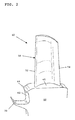
- FIG. 2 shows a perspective view of a portion of bucket 40.
- airfoil 50 includes a leading edge 52 and a trailing edge 54.
- Shank portion 60 includes a face 62 nearer leading edge 52 than trailing edge 54, disposed between angel wing 70 and platform lip 44.
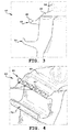
- FIG. 3 shows a cross-sectional side view of a portion of a turbine bucket 40 according to an embodiment of the invention. As can be seen in FIG. 3 , a distal end 48 of platform lip 44 is angled radially outward toward airfoil 50.
- FIG. 4 shows a perspective view of the bucket 40 of FIG. 3 .
- a plurality of voids 110 are provided along distal end 48 of platform lip 44.
- voids 110 are substantially trapezoidal in shape, although this is neither necessary nor essential. Voids having other shapes may also be employed, including, for example, rectangular, rhomboid, or arcuate shapes.
- FIG. 5 shows a perspective view of a bucket 40 according to another embodiment of the invention.
- platform lip 44 extends axially from platform 42 (i.e., a distal end is not angled toward airfoil 50, as in FIGS. 3 and 4 ).
- Voids 210 extend through platform lip 44 in an arcuate path such that remaining portions of platform lip 44 adjacent voids 210 include an arcuate face 45.
- FIG. 6 shows a perspective view of bucket 40.
- platform lip 44 includes an angled distal end 48, as in FIGS. 3 and 4 .
- voids 310 are formed in a body 46 of platform lip 44 rather than at its distal end 48.
- voids 310 may take any number of shapes, including, for example, rectangular, trapezoidal, rhomboid, arcuate, etc.
- FIGS. 7-9 show perspective views of other embodiments of the invention.
- voids 410 are elliptical in shape and angled with respect to a radial axis of bucket 40.
- elliptical voids 510 of differing sizes are employed with void size increasing along platform lip 44 from an end nearer the concave trailing face toward the convex leading face of airfoil 50.
- the effect of voids 510 on purge air between platform lip 44 and angel wing 70 will generally be more pronounced adjacent the larger voids. This may be desirable, for example, where a loss of purge air or an incursion of hot gas is greater in the area of the larger voids.
- elliptical voids 510 of differing size are employed with void size decreasing along platform lip 44 from an end nearer the concave trailing face toward the convex leading face of airfoil 50.
- such an embodiment may be desirable, for example, where a loss of purge air or an incursion of hot gas is greater in the area of the larger voids.
- FIGS. 10-13 show perspective views of turbine buckets 40 in accordance with various embodiments of the invention. In each of the embodiments in FIGS. 10-13 , voids are disposed unevenly along platform lip 44.
- a plurality of substantially rectangular voids 610 are disposed along platform lip 44 nearer the convex leading face than the concave trailing face of airfoil 50.
- the area of void concentration is opposite that in FIG. 10 , with the plurality of substantially rectangular voids 610 disposed along platform lip 44 nearer the concave trailing face than the convex leading face of airfoil 50.
- FIGS. 12 and 13 show embodiments similar to those in FIGS. 10 and 11 , respectively, in which voids 710 are rhomboid in shape rather than substantially rectangular.
- voids 710 are rhomboid in shape rather than substantially rectangular.
- the use of rhomboid voids 710 may be employed, for example, to direct purge air toward either convex leading face or concave trailing face of airfoil 50.
- FIG. 14 shows a schematic view of purge air flow in a typical turbine bucket.
- Purge air 80 is shown concentrated and having a higher swirl velocity in area 82, with a significant amount of escaping purge air 84 entering hot gas flowpath 28.
- FIG. 15 shows the effect of voids 110 on purge air 80 according to various embodiments of the invention.
- the area 83 in which purge air 80 is concentrated and exhibits a higher swirl velocity is distanced further from face 62 and toward a distal end of platform lip 44, as compared to FIG. 14 .
- This, in effect produces a curtaining effect, restricting incursion of hot gas 95 from hot gas flowpath 28 while at the same time reducing the quantity of escaping purge air from wheelspace 26 into hot gas flowpath 28.
- the overall quantity of purge air needed is reduced for at least two reasons.
- Each of these reductions to the total purge air required reduces the demand on the other system components, such as the compressor from which the purge air is provided.
- platform lip voids While reference above is made to the ability of platform lip voids to change the swirl velocity of purge air within a wheelspace, and particularly within a wheelspace adjacent early stage turbine buckets, it should be noted that platform lip voids may be employed on turbine buckets of any stage with similar changes to purge air swirl velocity and angle. In fact, Applicants have noted a very favorable result when platform lip voids are employed in the last stage bucket (LSB).
- LSB last stage bucket
- Platform lip voids according to various embodiments of the invention are capable of both increasing P T spikes at a diffuser inlet close to the inner radius while at the same time decreasing swirl spikes at or near the same location. Each of these improves diffuser performance.
- Platform lip voids for example, have been found to change the swirl angle of purge air exiting the LSB wheelspace by 1-3 degrees while also increasing P T spikes by 15-30%.
- FIG. 16 shows a schematic view of a LSB 40 adjacent diffuser 850.
- Hot gas 195 enters diffuser 850 at diffuser inlet plane 860 and passes toward struts 870.
- Platform lip voids according to embodiments of the invention reduce the swirl mismatch of purge air as it combines with hot gas 195, preventing separation of hot gas 195 as it enters struts 870. At the same time, such platform lip voids increase the P T spike.
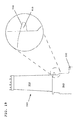
- FIG. 17 shows a graph of swirl spike as a function of diffuser inlet plane height.
- Profile A represents a swirl spike profile for a turbine having platform lip voids according to embodiments of the invention.
- Profile B represents a swirl spike profile for a turbine having a platform lip known in the art.
- Profile A exhibits a marked decrease in swirl spike at a radially inward position of the diffuser inlet plane.
- FIG. 18 shows a graph of P T spike as a function of diffuser inlet plane height.
- Profile A represents a P T spike profile for a turbine having platform lip voids according to embodiments of the invention.
- Profile B represents a P T spike profile for a turbine having a platform lip known in the art.
- Profile A exhibits an increase in P T spike at a radially inward position of the diffuser inlet plane.
- FIG. 19 shows a schematic cross-sectional view of a steam turbine bucket 940 having an airfoil 950 and a shank 960 affixed to a disk 990.
- a magnified view is provided of platform lip 944, along which voids 910 (shown in phantom) may be deployed similarly to the voids shown in FIGS. 3-5, 12, and 13 above.
Landscapes
- Engineering & Computer Science (AREA)
- Mechanical Engineering (AREA)
- General Engineering & Computer Science (AREA)
- Architecture (AREA)
- Physics & Mathematics (AREA)
- Fluid Mechanics (AREA)
- Turbine Rotor Nozzle Sealing (AREA)
- Structures Of Non-Positive Displacement Pumps (AREA)
Applications Claiming Priority (1)
| Application Number | Priority Date | Filing Date | Title |
|---|---|---|---|
| US14/603,321 US10590774B2 (en) | 2015-01-22 | 2015-01-22 | Turbine bucket for control of wheelspace purge air |
Publications (1)
| Publication Number | Publication Date |
|---|---|
| EP3048251A1 true EP3048251A1 (fr) | 2016-07-27 |
Family
ID=55177890
Family Applications (1)
| Application Number | Title | Priority Date | Filing Date |
|---|---|---|---|
| EP16152212.3A Pending EP3048251A1 (fr) | 2015-01-22 | 2016-01-21 | Aube de turbine pour une commande d'air de purge wheelspace |
Country Status (4)
| Country | Link |
|---|---|
| US (1) | US10590774B2 (fr) |
| EP (1) | EP3048251A1 (fr) |
| JP (1) | JP6749762B2 (fr) |
| CN (1) | CN105822352B (fr) |
Cited By (1)
| Publication number | Priority date | Publication date | Assignee | Title |
|---|---|---|---|---|
| FR3118783A1 (fr) * | 2021-01-14 | 2022-07-15 | Safran Aircraft Engines | Turbine a gaz haute-pression pour turbomachine |
Families Citing this family (10)
| Publication number | Priority date | Publication date | Assignee | Title |
|---|---|---|---|---|
| US10738638B2 (en) | 2015-01-22 | 2020-08-11 | General Electric Company | Rotor blade with wheel space swirlers and method for forming a rotor blade with wheel space swirlers |
| US9631509B1 (en) * | 2015-11-20 | 2017-04-25 | Siemens Energy, Inc. | Rim seal arrangement having pumping feature |
| US10683765B2 (en) * | 2017-02-14 | 2020-06-16 | General Electric Company | Turbine blades having shank features and methods of fabricating the same |
| US10753212B2 (en) * | 2017-08-23 | 2020-08-25 | Doosan Heavy Industries & Construction Co., Ltd | Turbine blade, turbine, and gas turbine having the same |
| KR102000281B1 (ko) * | 2017-10-11 | 2019-07-15 | 두산중공업 주식회사 | 압축기 및 이를 포함하는 가스 터빈 |
| DE102018207873A1 (de) * | 2018-05-18 | 2019-11-21 | MTU Aero Engines AG | Laufschaufel für eine Strömungsmaschine |
| JP7246959B2 (ja) | 2019-02-14 | 2023-03-28 | 三菱重工コンプレッサ株式会社 | タービン翼及び蒸気タービン |
| GB202004925D0 (en) * | 2020-02-13 | 2020-05-20 | Rolls Royce Plc | Aerofoil assembly and method |
| IT202000013609A1 (it) * | 2020-06-08 | 2021-12-08 | Ge Avio Srl | Componente di un motore a turbina con un insieme di deflettori |
| IT202000018631A1 (it) * | 2020-07-30 | 2022-01-30 | Ge Avio Srl | Pale di turbina comprendenti elementi di aero-freno e metodi per il loro uso. |
Citations (4)
| Publication number | Priority date | Publication date | Assignee | Title |
|---|---|---|---|---|
| US20060269399A1 (en) * | 2005-05-31 | 2006-11-30 | Pratt & Whitney Canada Corp. | Deflectors for controlling entry of fluid leakage into the working fluid flowpath of a gas turbine engine |
| EP2586995A2 (fr) * | 2011-10-26 | 2013-05-01 | General Electric Company | Éléments d'aile d'ange pour aube de turbine pour la commande d'écoulement de cavité avant et procédé associé |
| US20140003919A1 (en) * | 2012-06-27 | 2014-01-02 | Ching-Pang Lee | Finned seal assembly for gas turbine engines |
| US20140205443A1 (en) * | 2013-01-23 | 2014-07-24 | Siemens Aktiengesellschaft | Seal assembly including grooves in an aft facing side of a platform in a gas turbine engine |
Family Cites Families (32)
| Publication number | Priority date | Publication date | Assignee | Title |
|---|---|---|---|---|
| GB2251040B (en) | 1990-12-22 | 1994-06-22 | Rolls Royce Plc | Seal arrangement |
| US5211533A (en) | 1991-10-30 | 1993-05-18 | General Electric Company | Flow diverter for turbomachinery seals |
| GB9305010D0 (en) * | 1993-03-11 | 1993-04-28 | Rolls Royce Plc | A cooled turbine nozzle assembly and a method of calculating the diameters of cooling holes for use in such an assembly |
| US5893984A (en) * | 1995-10-27 | 1999-04-13 | General Electric Company | High aspect ratio EDM electrode assembly |
| US6077035A (en) | 1998-03-27 | 2000-06-20 | Pratt & Whitney Canada Corp. | Deflector for controlling entry of cooling air leakage into the gaspath of a gas turbine engine |
| JP4508482B2 (ja) | 2001-07-11 | 2010-07-21 | 三菱重工業株式会社 | ガスタービン静翼 |
| DE10295864D2 (de) | 2001-12-14 | 2004-11-04 | Alstom Technology Ltd Baden | Gasturbinenanordnung |
| JP2004100578A (ja) | 2002-09-10 | 2004-04-02 | Mitsubishi Heavy Ind Ltd | 軸流タービンの翼部構造 |
| US7114339B2 (en) | 2004-03-30 | 2006-10-03 | United Technologies Corporation | Cavity on-board injection for leakage flows |
| GB2417053B (en) | 2004-08-11 | 2006-07-12 | Rolls Royce Plc | Turbine |
| US7189055B2 (en) | 2005-05-31 | 2007-03-13 | Pratt & Whitney Canada Corp. | Coverplate deflectors for redirecting a fluid flow |
| US7189056B2 (en) | 2005-05-31 | 2007-03-13 | Pratt & Whitney Canada Corp. | Blade and disk radial pre-swirlers |
| US7465152B2 (en) | 2005-09-16 | 2008-12-16 | General Electric Company | Angel wing seals for turbine blades and methods for selecting stator, rotor and wing seal profiles |
| US7500824B2 (en) | 2006-08-22 | 2009-03-10 | General Electric Company | Angel wing abradable seal and sealing method |
| GB0808206D0 (en) | 2008-05-07 | 2008-06-11 | Rolls Royce Plc | A blade arrangement |
| US8057178B2 (en) * | 2008-09-04 | 2011-11-15 | General Electric Company | Turbine bucket for a turbomachine and method of reducing bow wave effects at a turbine bucket |
| US8075256B2 (en) | 2008-09-25 | 2011-12-13 | Siemens Energy, Inc. | Ingestion resistant seal assembly |
| US8419356B2 (en) * | 2008-09-25 | 2013-04-16 | Siemens Energy, Inc. | Turbine seal assembly |
| US8083475B2 (en) | 2009-01-13 | 2011-12-27 | General Electric Company | Turbine bucket angel wing compression seal |
| DE102009040758A1 (de) | 2009-09-10 | 2011-03-17 | Mtu Aero Engines Gmbh | Umlenkvorrichtung für einen Leckagestrom in einer Gasturbine und Gasturbine |
| US20120163955A1 (en) | 2010-12-23 | 2012-06-28 | General Electric Company | System and method to eliminate a hard rub and optimize a purge flow in a gas turbine |
| US20120251291A1 (en) | 2011-03-31 | 2012-10-04 | General Electric Company | Stator-rotor assemblies with features for enhanced containment of gas flow, and related processes |
| US20130089430A1 (en) | 2011-10-11 | 2013-04-11 | General Electric Company | Turbomachine component having a flow contour feature |
| US8979481B2 (en) * | 2011-10-26 | 2015-03-17 | General Electric Company | Turbine bucket angel wing features for forward cavity flow control and related method |
| US20130170983A1 (en) | 2012-01-04 | 2013-07-04 | General Electric Company | Turbine assembly and method for reducing fluid flow between turbine components |
| US8683814B2 (en) * | 2012-02-15 | 2014-04-01 | United Technologies Corporation | Gas turbine engine component with impingement and lobed cooling hole |
| US9482098B2 (en) | 2012-05-11 | 2016-11-01 | United Technologies Corporation | Convective shielding cooling hole pattern |
| US8926283B2 (en) | 2012-11-29 | 2015-01-06 | Siemens Aktiengesellschaft | Turbine blade angel wing with pumping features |
| US9039357B2 (en) * | 2013-01-23 | 2015-05-26 | Siemens Aktiengesellschaft | Seal assembly including grooves in a radially outwardly facing side of a platform in a gas turbine engine |
| US9068513B2 (en) | 2013-01-23 | 2015-06-30 | Siemens Aktiengesellschaft | Seal assembly including grooves in an inner shroud in a gas turbine engine |
| US8939711B2 (en) * | 2013-02-15 | 2015-01-27 | Siemens Aktiengesellschaft | Outer rim seal assembly in a turbine engine |
| US9828880B2 (en) | 2013-03-15 | 2017-11-28 | General Electric Company | Method and apparatus to improve heat transfer in turbine sections of gas turbines |
-
2015
- 2015-01-22 US US14/603,321 patent/US10590774B2/en active Active
-
2016
- 2016-01-15 JP JP2016005703A patent/JP6749762B2/ja active Active
- 2016-01-21 EP EP16152212.3A patent/EP3048251A1/fr active Pending
- 2016-01-22 CN CN201610042591.8A patent/CN105822352B/zh active Active
Patent Citations (4)
| Publication number | Priority date | Publication date | Assignee | Title |
|---|---|---|---|---|
| US20060269399A1 (en) * | 2005-05-31 | 2006-11-30 | Pratt & Whitney Canada Corp. | Deflectors for controlling entry of fluid leakage into the working fluid flowpath of a gas turbine engine |
| EP2586995A2 (fr) * | 2011-10-26 | 2013-05-01 | General Electric Company | Éléments d'aile d'ange pour aube de turbine pour la commande d'écoulement de cavité avant et procédé associé |
| US20140003919A1 (en) * | 2012-06-27 | 2014-01-02 | Ching-Pang Lee | Finned seal assembly for gas turbine engines |
| US20140205443A1 (en) * | 2013-01-23 | 2014-07-24 | Siemens Aktiengesellschaft | Seal assembly including grooves in an aft facing side of a platform in a gas turbine engine |
Cited By (1)
| Publication number | Priority date | Publication date | Assignee | Title |
|---|---|---|---|---|
| FR3118783A1 (fr) * | 2021-01-14 | 2022-07-15 | Safran Aircraft Engines | Turbine a gaz haute-pression pour turbomachine |
Also Published As
| Publication number | Publication date |
|---|---|
| JP2016138551A (ja) | 2016-08-04 |
| CN105822352A (zh) | 2016-08-03 |
| CN105822352B (zh) | 2020-06-09 |
| US20160215626A1 (en) | 2016-07-28 |
| JP6749762B2 (ja) | 2020-09-02 |
| US10590774B2 (en) | 2020-03-17 |
Similar Documents
| Publication | Publication Date | Title |
|---|---|---|
| EP3048251A1 (fr) | Aube de turbine pour une commande d'air de purge wheelspace | |
| US20150071763A1 (en) | Outer rim seal assembly in a turbine engine | |
| US8845284B2 (en) | Apparatus and system for sealing a turbine rotor | |
| EP3064709A1 (fr) | Plate-forme d'aube de turbine pour influencer les pertes d'incursion de gaz chaude | |
| US8870535B2 (en) | Airfoil | |
| EP3047104B1 (fr) | Turbomachine avec paroi contourée | |
| JP6461382B2 (ja) | シュラウド付きタービンブレード | |
| EP3056667A2 (fr) | Aube de turbine pour une commande d'air de purge d'espace de la roue | |
| EP2415970A2 (fr) | Ensemble d'étanchéité | |
| US10883373B2 (en) | Blade tip seal | |
| JP2016125486A (ja) | ガスタービンシール | |
| EP3048249A1 (fr) | Aube de turbine pour une commande d'air de purge wheelspace | |
| US10544695B2 (en) | Turbine bucket for control of wheelspace purge air | |
| EP2354465A2 (fr) | Mécanisme d'étanchéité de gradient de pression adverse | |
| US10370987B2 (en) | Blade or vane row and gas turbine | |
| EP3020930B1 (fr) | Plate-forme avec des caractéristiques de bord d'attaque | |
| JP2011099438A (ja) | 蒸気通路流れ剥離低減システム | |
| JP5852191B2 (ja) | 端壁部材及びガスタービン | |
| WO2016033465A1 (fr) | Éléments de guidage de flux pour carénage d'extrémité d'aube de turbine à gaz | |
| US10570743B2 (en) | Turbomachine having an annulus enlargment and airfoil | |
| JP5591986B2 (ja) | 端壁部材及びガスタービン | |
| JP2014199058A (ja) | 端壁部材及びガスタービン |
Legal Events
| Date | Code | Title | Description |
|---|---|---|---|
| PUAI | Public reference made under article 153(3) epc to a published international application that has entered the european phase |
Free format text: ORIGINAL CODE: 0009012 |
|
| AK | Designated contracting states |
Kind code of ref document: A1 Designated state(s): AL AT BE BG CH CY CZ DE DK EE ES FI FR GB GR HR HU IE IS IT LI LT LU LV MC MK MT NL NO PL PT RO RS SE SI SK SM TR |
|
| AX | Request for extension of the european patent |
Extension state: BA ME |
|
| STAA | Information on the status of an ep patent application or granted ep patent |
Free format text: STATUS: REQUEST FOR EXAMINATION WAS MADE |
|
| 17P | Request for examination filed |
Effective date: 20170127 |
|
| RBV | Designated contracting states (corrected) |
Designated state(s): AL AT BE BG CH CY CZ DE DK EE ES FI FR GB GR HR HU IE IS IT LI LT LU LV MC MK MT NL NO PL PT RO RS SE SI SK SM TR |
|
| STAA | Information on the status of an ep patent application or granted ep patent |
Free format text: STATUS: EXAMINATION IS IN PROGRESS |
|
| 17Q | First examination report despatched |
Effective date: 20191217 |
|
| STAA | Information on the status of an ep patent application or granted ep patent |
Free format text: STATUS: EXAMINATION IS IN PROGRESS |
|
| STAA | Information on the status of an ep patent application or granted ep patent |
Free format text: STATUS: EXAMINATION IS IN PROGRESS |
|
| RAP1 | Party data changed (applicant data changed or rights of an application transferred) |
Owner name: GENERAL ELECTRIC TECHNOLOGY GMBH |
|
| GRAP | Despatch of communication of intention to grant a patent |
Free format text: ORIGINAL CODE: EPIDOSNIGR1 |
|
| STAA | Information on the status of an ep patent application or granted ep patent |
Free format text: STATUS: GRANT OF PATENT IS INTENDED |
|
| INTG | Intention to grant announced |
Effective date: 20240529 |