EP3048017A1 - Damping force generation device for vehicle - Google Patents
Damping force generation device for vehicle Download PDFInfo
- Publication number
- EP3048017A1 EP3048017A1 EP16152277.6A EP16152277A EP3048017A1 EP 3048017 A1 EP3048017 A1 EP 3048017A1 EP 16152277 A EP16152277 A EP 16152277A EP 3048017 A1 EP3048017 A1 EP 3048017A1
- Authority
- EP
- European Patent Office
- Prior art keywords
- cylinder
- shock absorber
- damping force
- charge
- piston
- Prior art date
- Legal status (The legal status is an assumption and is not a legal conclusion. Google has not performed a legal analysis and makes no representation as to the accuracy of the status listed.)
- Granted
Links
- 238000013016 damping Methods 0.000 title claims abstract description 116
- 239000006096 absorbing agent Substances 0.000 claims abstract description 112
- 230000035939 shock Effects 0.000 claims abstract description 112
- 229910052751 metal Inorganic materials 0.000 claims description 57
- 239000002184 metal Substances 0.000 claims description 57
- 239000007788 liquid Substances 0.000 claims description 50
- 239000000428 dust Substances 0.000 claims description 46
- 239000011888 foil Substances 0.000 claims description 34
- 150000002500 ions Chemical class 0.000 claims description 23
- 239000011347 resin Substances 0.000 claims description 17
- 229920005989 resin Polymers 0.000 claims description 17
- 239000000853 adhesive Substances 0.000 claims description 14
- 230000001070 adhesive effect Effects 0.000 claims description 14
- 230000008859 change Effects 0.000 claims description 10
- 238000006073 displacement reaction Methods 0.000 claims description 5
- 238000006243 chemical reaction Methods 0.000 claims description 4
- 239000003921 oil Substances 0.000 description 95
- 230000001965 increasing effect Effects 0.000 description 27
- 230000008602 contraction Effects 0.000 description 22
- 230000000694 effects Effects 0.000 description 16
- 239000000725 suspension Substances 0.000 description 14
- 230000002093 peripheral effect Effects 0.000 description 8
- 239000007789 gas Substances 0.000 description 7
- 241001247986 Calotropis procera Species 0.000 description 6
- 239000011248 coating agent Substances 0.000 description 6
- 238000000576 coating method Methods 0.000 description 6
- 230000006835 compression Effects 0.000 description 6
- 238000007906 compression Methods 0.000 description 6
- 238000003466 welding Methods 0.000 description 6
- IJGRMHOSHXDMSA-UHFFFAOYSA-N Atomic nitrogen Chemical compound N#N IJGRMHOSHXDMSA-UHFFFAOYSA-N 0.000 description 4
- 230000005611 electricity Effects 0.000 description 4
- 230000009467 reduction Effects 0.000 description 4
- 230000003068 static effect Effects 0.000 description 4
- 230000007246 mechanism Effects 0.000 description 3
- 238000000926 separation method Methods 0.000 description 3
- 239000004820 Pressure-sensitive adhesive Substances 0.000 description 2
- 229910000831 Steel Inorganic materials 0.000 description 2
- 229910052782 aluminium Inorganic materials 0.000 description 2
- XAGFODPZIPBFFR-UHFFFAOYSA-N aluminium Chemical compound [Al] XAGFODPZIPBFFR-UHFFFAOYSA-N 0.000 description 2
- 230000002708 enhancing effect Effects 0.000 description 2
- 238000002474 experimental method Methods 0.000 description 2
- 238000009434 installation Methods 0.000 description 2
- 238000006386 neutralization reaction Methods 0.000 description 2
- 229910052757 nitrogen Inorganic materials 0.000 description 2
- 239000007787 solid Substances 0.000 description 2
- 239000010959 steel Substances 0.000 description 2
- RYGMFSIKBFXOCR-UHFFFAOYSA-N Copper Chemical compound [Cu] RYGMFSIKBFXOCR-UHFFFAOYSA-N 0.000 description 1
- BQCADISMDOOEFD-UHFFFAOYSA-N Silver Chemical compound [Ag] BQCADISMDOOEFD-UHFFFAOYSA-N 0.000 description 1
- 230000002411 adverse Effects 0.000 description 1
- 239000000956 alloy Substances 0.000 description 1
- 229910045601 alloy Inorganic materials 0.000 description 1
- 239000000919 ceramic Substances 0.000 description 1
- 238000004891 communication Methods 0.000 description 1
- 239000002131 composite material Substances 0.000 description 1
- 229910052802 copper Inorganic materials 0.000 description 1
- 239000010949 copper Substances 0.000 description 1
- 230000008878 coupling Effects 0.000 description 1
- 238000010168 coupling process Methods 0.000 description 1
- 238000005859 coupling reaction Methods 0.000 description 1
- 239000012530 fluid Substances 0.000 description 1
- PCHJSUWPFVWCPO-UHFFFAOYSA-N gold Chemical compound [Au] PCHJSUWPFVWCPO-UHFFFAOYSA-N 0.000 description 1
- 229910052737 gold Inorganic materials 0.000 description 1
- 239000010931 gold Substances 0.000 description 1
- 238000011835 investigation Methods 0.000 description 1
- 239000000463 material Substances 0.000 description 1
- 239000007769 metal material Substances 0.000 description 1
- 230000004048 modification Effects 0.000 description 1
- 238000012986 modification Methods 0.000 description 1
- 238000012545 processing Methods 0.000 description 1
- 238000011160 research Methods 0.000 description 1
- 238000010008 shearing Methods 0.000 description 1
- 229910052710 silicon Inorganic materials 0.000 description 1
- 239000010703 silicon Substances 0.000 description 1
- 229910052709 silver Inorganic materials 0.000 description 1
- 239000004332 silver Substances 0.000 description 1
- 230000003746 surface roughness Effects 0.000 description 1
Images






Classifications
-
- B—PERFORMING OPERATIONS; TRANSPORTING
- B60—VEHICLES IN GENERAL
- B60G—VEHICLE SUSPENSION ARRANGEMENTS
- B60G13/00—Resilient suspensions characterised by arrangement, location or type of vibration dampers
- B60G13/02—Resilient suspensions characterised by arrangement, location or type of vibration dampers having dampers dissipating energy, e.g. frictionally
- B60G13/06—Resilient suspensions characterised by arrangement, location or type of vibration dampers having dampers dissipating energy, e.g. frictionally of fluid type
- B60G13/08—Resilient suspensions characterised by arrangement, location or type of vibration dampers having dampers dissipating energy, e.g. frictionally of fluid type hydraulic
-
- B—PERFORMING OPERATIONS; TRANSPORTING
- B60—VEHICLES IN GENERAL
- B60R—VEHICLES, VEHICLE FITTINGS, OR VEHICLE PARTS, NOT OTHERWISE PROVIDED FOR
- B60R16/00—Electric or fluid circuits specially adapted for vehicles and not otherwise provided for; Arrangement of elements of electric or fluid circuits specially adapted for vehicles and not otherwise provided for
- B60R16/02—Electric or fluid circuits specially adapted for vehicles and not otherwise provided for; Arrangement of elements of electric or fluid circuits specially adapted for vehicles and not otherwise provided for electric constitutive elements
- B60R16/06—Electric or fluid circuits specially adapted for vehicles and not otherwise provided for; Arrangement of elements of electric or fluid circuits specially adapted for vehicles and not otherwise provided for electric constitutive elements for removing electrostatic charges
-
- B—PERFORMING OPERATIONS; TRANSPORTING
- B60—VEHICLES IN GENERAL
- B60G—VEHICLE SUSPENSION ARRANGEMENTS
- B60G15/00—Resilient suspensions characterised by arrangement, location or type of combined spring and vibration damper, e.g. telescopic type
- B60G15/02—Resilient suspensions characterised by arrangement, location or type of combined spring and vibration damper, e.g. telescopic type having mechanical spring
- B60G15/06—Resilient suspensions characterised by arrangement, location or type of combined spring and vibration damper, e.g. telescopic type having mechanical spring and fluid damper
- B60G15/062—Resilient suspensions characterised by arrangement, location or type of combined spring and vibration damper, e.g. telescopic type having mechanical spring and fluid damper the spring being arranged around the damper
-
- F—MECHANICAL ENGINEERING; LIGHTING; HEATING; WEAPONS; BLASTING
- F16—ENGINEERING ELEMENTS AND UNITS; GENERAL MEASURES FOR PRODUCING AND MAINTAINING EFFECTIVE FUNCTIONING OF MACHINES OR INSTALLATIONS; THERMAL INSULATION IN GENERAL
- F16F—SPRINGS; SHOCK-ABSORBERS; MEANS FOR DAMPING VIBRATION
- F16F9/00—Springs, vibration-dampers, shock-absorbers, or similarly-constructed movement-dampers using a fluid or the equivalent as damping medium
- F16F9/32—Details
- F16F9/3207—Constructional features
-
- F—MECHANICAL ENGINEERING; LIGHTING; HEATING; WEAPONS; BLASTING
- F16—ENGINEERING ELEMENTS AND UNITS; GENERAL MEASURES FOR PRODUCING AND MAINTAINING EFFECTIVE FUNCTIONING OF MACHINES OR INSTALLATIONS; THERMAL INSULATION IN GENERAL
- F16F—SPRINGS; SHOCK-ABSORBERS; MEANS FOR DAMPING VIBRATION
- F16F9/00—Springs, vibration-dampers, shock-absorbers, or similarly-constructed movement-dampers using a fluid or the equivalent as damping medium
- F16F9/32—Details
- F16F9/3207—Constructional features
- F16F9/3235—Constructional features of cylinders
-
- F—MECHANICAL ENGINEERING; LIGHTING; HEATING; WEAPONS; BLASTING
- F16—ENGINEERING ELEMENTS AND UNITS; GENERAL MEASURES FOR PRODUCING AND MAINTAINING EFFECTIVE FUNCTIONING OF MACHINES OR INSTALLATIONS; THERMAL INSULATION IN GENERAL
- F16F—SPRINGS; SHOCK-ABSORBERS; MEANS FOR DAMPING VIBRATION
- F16F9/00—Springs, vibration-dampers, shock-absorbers, or similarly-constructed movement-dampers using a fluid or the equivalent as damping medium
- F16F9/32—Details
- F16F9/44—Means on or in the damper for manual or non-automatic adjustment; such means combined with temperature correction
- F16F9/46—Means on or in the damper for manual or non-automatic adjustment; such means combined with temperature correction allowing control from a distance, i.e. location of means for control input being remote from site of valves, e.g. on damper external wall
-
- F—MECHANICAL ENGINEERING; LIGHTING; HEATING; WEAPONS; BLASTING
- F16—ENGINEERING ELEMENTS AND UNITS; GENERAL MEASURES FOR PRODUCING AND MAINTAINING EFFECTIVE FUNCTIONING OF MACHINES OR INSTALLATIONS; THERMAL INSULATION IN GENERAL
- F16F—SPRINGS; SHOCK-ABSORBERS; MEANS FOR DAMPING VIBRATION
- F16F9/00—Springs, vibration-dampers, shock-absorbers, or similarly-constructed movement-dampers using a fluid or the equivalent as damping medium
- F16F9/32—Details
- F16F9/54—Arrangements for attachment
-
- H—ELECTRICITY
- H05—ELECTRIC TECHNIQUES NOT OTHERWISE PROVIDED FOR
- H05F—STATIC ELECTRICITY; NATURALLY-OCCURRING ELECTRICITY
- H05F3/00—Carrying-off electrostatic charges
- H05F3/06—Carrying-off electrostatic charges by means of ionising radiation
-
- B—PERFORMING OPERATIONS; TRANSPORTING
- B60—VEHICLES IN GENERAL
- B60G—VEHICLE SUSPENSION ARRANGEMENTS
- B60G2202/00—Indexing codes relating to the type of spring, damper or actuator
- B60G2202/20—Type of damper
- B60G2202/24—Fluid damper
-
- B—PERFORMING OPERATIONS; TRANSPORTING
- B60—VEHICLES IN GENERAL
- B60G—VEHICLE SUSPENSION ARRANGEMENTS
- B60G2206/00—Indexing codes related to the manufacturing of suspensions: constructional features, the materials used, procedures or tools
- B60G2206/01—Constructional features of suspension elements, e.g. arms, dampers, springs
- B60G2206/40—Constructional features of dampers and/or springs
- B60G2206/41—Dampers
-
- F—MECHANICAL ENGINEERING; LIGHTING; HEATING; WEAPONS; BLASTING
- F16—ENGINEERING ELEMENTS AND UNITS; GENERAL MEASURES FOR PRODUCING AND MAINTAINING EFFECTIVE FUNCTIONING OF MACHINES OR INSTALLATIONS; THERMAL INSULATION IN GENERAL
- F16F—SPRINGS; SHOCK-ABSORBERS; MEANS FOR DAMPING VIBRATION
- F16F2230/00—Purpose; Design features
- F16F2230/0023—Purpose; Design features protective
-
- F—MECHANICAL ENGINEERING; LIGHTING; HEATING; WEAPONS; BLASTING
- F16—ENGINEERING ELEMENTS AND UNITS; GENERAL MEASURES FOR PRODUCING AND MAINTAINING EFFECTIVE FUNCTIONING OF MACHINES OR INSTALLATIONS; THERMAL INSULATION IN GENERAL
- F16F—SPRINGS; SHOCK-ABSORBERS; MEANS FOR DAMPING VIBRATION
- F16F2230/00—Purpose; Design features
- F16F2230/10—Enclosure elements, e.g. for protection
-
- F—MECHANICAL ENGINEERING; LIGHTING; HEATING; WEAPONS; BLASTING
- F16—ENGINEERING ELEMENTS AND UNITS; GENERAL MEASURES FOR PRODUCING AND MAINTAINING EFFECTIVE FUNCTIONING OF MACHINES OR INSTALLATIONS; THERMAL INSULATION IN GENERAL
- F16F—SPRINGS; SHOCK-ABSORBERS; MEANS FOR DAMPING VIBRATION
- F16F9/00—Springs, vibration-dampers, shock-absorbers, or similarly-constructed movement-dampers using a fluid or the equivalent as damping medium
- F16F9/32—Details
- F16F9/38—Covers for protection or appearance
Definitions
- the present invention relates to a damping force generation device for a vehicle, and more particularly, to a damping force generation device including a shock absorber.
- Static electricity is generated in the vehicle due to the flow of air in a state in which the air is brought into friction contact with the vehicle. Static electricity is also generated when each portion of a tire is repeatedly brought into contact with a road surface and separated therefrom along with the rotation of a wheel, when components in an engine, a brake device, or the like move relatively under a contact state, and the like.
- the vehicle is substantially electrically insulated from the ground due to a tire having low conductivity, and hence electric charge (in general, positive electric charge) is charged to a vehicle body or the like when static electricity is generated in the vehicle. Radio noise is liable to be generated when the electric charge is charged to the vehicle body or the like. Therefore, a structure for reducing electric charge that is charged to a vehicle through the passage of an electric current has been investigated hitherto, and various structures have been proposed.
- an electrostatic eliminator having such a configuration that charged silicon is filled into a case in which ceramic bodies are arranged densely in a radial fashion, and one of conductive wires connected to both sides of the case is connected to a minus terminal of a battery and the other conductive wire is connected to a vehicle body.
- static electricity of the vehicle body is neutralized by grounding, and thus the electric charge that is charged to the vehicle body can be reduced.
- the related-art electrostatic eliminator as disclosed in Japanese Patent Application Laid-open No. 2009-181694 has a complicated structure, and hence the electrostatic eliminator is required to be connected to the minus terminal of the battery and the vehicle body through the conductive wires, with the result that an installation space for the electrostatic eliminator is also required.
- the vehicle includes damping force generation devices configured to damp vibrations of the vehicle body.
- Each of the damping force generation devices includes a shock absorber having a cylinder and a piston fitted to the cylinder in a reciprocally movable manner.
- the shock absorber is coupled to a sprung member and an unsprung member of the vehicle at a rod part of the piston and the cylinder, respectively, and generates the damping force due to a flow resistance when oil passes through orifices formed in the piston along with relative displacement between the sprung member and the unsprung member.
- the related-art electrostatic eliminator as disclosed in Japanese Patent Application Laid-open No. 2009-181694 is restricted in terms of an installation location, and cannot thus be installed at a location for effectively reducing the electric charge that is charged to the oil in the shock absorbers. Therefore, the excessive damping force resulting from the increase in the viscosity of the oil caused by the charging of the electric charge cannot be effectively prevented by the related-art electrostatic eliminator.
- the present invention has been made in view of the above-mentioned phenomenon and the cause of the phenomenon, which have not been recognized hitherto. It is a primary object of the present invention to prevent electric charge from being excessively charged to oil in a shock absorber, thereby preventing viscosity of the oil from being increased by the charging of the electric charge to generate an excessive damping force.
- a damping force generation device for a vehicle, including a shock absorber including: a cylinder; and a piston fitted into the cylinder in a reciprocally movable manner to form two cylinder chambers in cooperation with the cylinder, the shock absorber being coupleable to one of a sprung member and an unsprung member of the vehicle at a rod part of the piston, and to another one of the sprung member and the unsprung member at the cylinder, the sprung member being kept substantially electrically insulated from a road, and the shock absorber being configured to generate a damping force due to a flow resistance when a working liquid passes through an orifice formed in a main body part of the piston to move between the two cylinder chambers along with relative displacement between the sprung member and the unsprung member.
- the damping force generation device for a vehicle further includes a self-discharge type charge eliminator provided on a surface of a specific member being at least one of a member constructing the shock absorber or an auxiliary member connected to the shock absorber.
- the self-discharge type charge eliminator is an air-ion conversion self-discharge type charge eliminator configured to reduce a charge amount of positive electric charge, which is charged to the specific member, through diselectrification carried out by changing air around the air-ion conversion self-discharge type charge eliminator into negative air ions depending on the charge amount of the specific member, and by causing the negative air ions to be attracted to the positive electric charge of the specific member to neutralize the positive electric charge, to thereby reduce a charge amount of the working liquid.
- a reason for the charging of the electric charge to the working liquid such as the oil in the shock absorber when the electric charge is charged to the vehicle body and the like, and a cause of the increase in the viscosity of the working fluid when the electric charge is charged to the working liquid are not necessarily apparent, but major reason and cause are considered as follows.
- the shock absorber is coupled to one of and another one of the sprung member and the unsprung member of the vehicle at the rod part of the piston and the cylinder, respectively.
- the electric charge moves to the piston and the cylinder through the sprung member and the unsprung member, respectively.
- the damping force generation device for a vehicle includes the self-discharge type charge eliminator provided on the surface of the specific member being at least one of the member constructing the shock absorber or the auxiliary member connected to the shock absorber.
- the charge eliminator reduces the charge amount of the specific member through diselectrification carried out by changing the air around the charge eliminator into negative air ions, and by causing the negative air ions to be attracted to the positive electric charge of the specific member to neutralize the positive electric charge.
- the charge amount of the working liquid is reduced through the movement of the electric charge that is charged to the working liquid in the shock absorber to the specific member, thereby being capable of preventing such a state that the viscosity of the working liquid is increased by the excessive charging of the electric charge to generate the excessive damping force.
- an electrostatic eliminator having a complicated structure may be omitted, and hence the electrostatic eliminator need not be connected to a minus terminal of a battery or a vehicle body through conductive wires.
- the self-discharge type charge eliminator may be, for example, a thin conductive body capable of carrying out so-called self-discharge through use of electric charge that is charged to the specific member, and hence a large space as in the case of installing the electrostatic eliminator is not required.
- the specific member is a dust boot made of a resin as the auxiliary member connected to the rod part, the self-discharge type charge eliminator is provided on a surface of the dust boot, and the rod part and the dust boot are connected to each other so that the positive electric charge is movable from the rod part to the dust boot.
- the self-discharge type charge eliminator is provided on the surface of the dust boot.
- the dust boot is made of a resin, to which the electric charge is charged more easily than to a metal.
- the rod part and the dust boot are connected to each other so that the electric charge is movable from the rod part to the dust boot.
- the dust boot is diselectrified by the self-discharge type charge eliminator so that the electric charge that is charged to the piston moves to the dust boot via the rod part, and the electric charge that is charged to the working liquid thus moves to the piston.
- the charge amount of the working liquid can be reduced, thereby being capable of preventing such a state that the viscosity of the working liquid is increased by the excessive charging of the electric charge to generate the excessive damping force.
- the shock absorber is a twin-tube shock absorber including: an inner cylinder to which the piston is fitted; and an outer cylinder surrounding the inner cylinder, the specific member is the outer cylinder, and the self-discharge type charge eliminator is provided on a surface of the outer cylinder below a liquid level of the working liquid between the inner cylinder and the outer cylinder when the vehicle is in a standard load state.
- the self-discharge type charge eliminator is provided on the surface of the outer cylinder below the liquid level of the working liquid between the inner cylinder and the outer cylinder when the vehicle is in the standard load state.
- the working liquid between the inner cylinder and the outer cylinder can efficiently be diselectrified.
- the inner cylinder can efficiently be diselectrified so that the electric charge that is charged to the working liquid in the inner cylinder can efficiently be moved to the inner cylinder, and the working liquid in the inner cylinder can thus efficiently be diselectrified.
- the shock absorber is a twin-tube shock absorber including: an inner cylinder to which the piston is fitted; an outer cylinder surrounding the inner cylinder to form a reservoir chamber between the inner cylinder and the outer cylinder; a base valve assembly; and an end cap closing end portions of the inner cylinder and the outer cylinder to define a base valve chamber communicating with the reservoir chamber in cooperation with the base valve assembly, the specific member is at least one of the outer cylinder or the end cap, and the positive electric charge is movable from the inner cylinder to the specific member.
- the self-discharge type charge eliminator is provided on the surface of at least one of the outer cylinder or the end cap, which is the specific member, and the electric charge is movable from the inner cylinder to the specific member.
- the specific member is diselectrified by the charge eliminator, the electric charge moves from the inner cylinder to the specific member so that the electric potential of the inner cylinder is reduced.
- the electric charge that is charged to the working liquid in the inner cylinder moves to the inner cylinder.
- the charge amount of the working liquid in the inner cylinder can be reduced, thereby being capable of preventing such a state that the viscosity of the working liquid is increased by the excessive charging of the electric charge to generate the excessive damping force.
- the shock absorber is a mono-tube shock absorber
- the specific member is the cylinder
- the self-discharge type charge eliminator is provided on a surface of the cylinder so that at least a part of the self-discharge type charge eliminator is positioned within a predetermined range corresponding to a range in a direction of the relative displacement, in which the main body part of the piston exists when the vehicle is in a standard load state.
- the self-discharge type charge eliminator is provided on the surface of the cylinder.
- the electric potential of the cylinder is reduced. Consequently, the electric charge that is charged to the working liquid moves to the cylinder.
- the charge amount in the working liquid can be reduced, thereby being capable of preventing such a state that the viscosity of the working liquid is increased by the excessive charging of the electric charge to generate the excessive damping force.
- the diselectrification for the working liquid existing around the main body part of the piston in which the orifice is formed can efficiently be carried out.
- the shock absorber is a variable damping force shock absorber including: a bypass passage for bypassing the main body part of the piston to connect the two cylinder chambers to each other; a variable orifice formed in the bypass passage; and an effective passage cross sectional area changing device configured to change an effective passage cross sectional area of the variable orifice, the variable damping force shock absorber being configured such that, when the piston is displaced with respect to the cylinder, at least a part of the working liquid in one of the two cylinder chambers moves to another one of the two cylinder chambers through the bypass passage, the specific member is the effective passage cross sectional area changing device, and the positive electric charge is movable from the working liquid passing through the bypass passage to the effective passage cross sectional area changing device.
- the self-discharge type charge eliminator is provided on the surface of the effective passage cross sectional area changing device configured to change the effective passage cross sectional area of the variable orifice formed in the bypass passage. Further, the electric charge can move from the working liquid passing through the bypass passage to the effective passage cross sectional area changing device.
- the effective passage cross sectional area changing device is diselectrified by the self-discharge type charge eliminator so that the electric charge that is charged to the working liquid moves to the effective passage cross sectional area changing device, and the electric charge that is charged to the working liquid passing through the bypass passage is thus reduced.
- the self-discharge type charge eliminator includes: a conductive metal foil having a large number of minute protrusions and recesses formed on a side surface on an outer periphery of the conductive metal foil; and a layer of an adhesive applied to one surface of the conductive metal foil, and the self-discharge type charge eliminator is fixed to the specific member by bonding with the layer of the adhesive.
- the metal foil for the diselectrification can easily be fixed by the bonding to the surface of the specific member. Further, the metal foil is brought into close contact with the specific member through intermediation of the layer of the adhesive across the entire surface, and hence the electric charge can efficiently be moved from the specific member to the metal foil, thereby being capable of enhancing the effect of the diselectrification.
- FIG. 1 is a schematic view for illustrating a damping force generation device 10 according to a first embodiment of the present invention applied to a MacPherson strut front suspension when viewed from the rear of a vehicle.
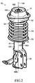
- FIG. 2 is a perspective view of the damping force generation device 10 illustrated in FIG. 1 .
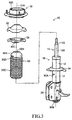
- FIG. 3 is an exploded perspective view of the damping force generation device 10 illustrated in FIG. 1 .
- the damping force generation device 10 includes a shock absorber 16 including a cylinder 12 and a piston 14.
- the piston 14 is fitted to the cylinder 12 so as to be reciprocally movable with respect to the cylinder 12 along an axis 12A.
- the cylinder 12 and the piston 14 are made of a metal such as steel.
- a rod part 14R of the piston 14 extends upward through a top end of the cylinder 12.
- members described below are made of a conductive metal such as steel except for members whose forming materials are particularly described.
- Metal members including the cylinder 12 and the piston 14 are coated for increasing durability, and surfaces are covered by non-conductive coating films.
- the shock absorber 16 is coupled to a vehicle body 22 serving as a sprung member of a vehicle 20 at a top end portion of the rod part 14R through intermediation of an upper support 18, and is coupled to a wheel carrier 26 serving as an unsprung member of the vehicle 20 through intermediation of a bracket 24 fixed to a bottom end portion of the cylinder 12.
- the upper support 18 supports the rod part 14R through use of a rubber bush device arranged inside a casing 18A.
- the wheel carrier 26 supports a spindle 30 of a wheel 28 so as to be rotatable about a rotational axis 32 through intermediation of a bearing (not shown).
- the bottom end portion of the shock absorber 16 may be coupled to the wheel carrier 26 or a suspension member in a relatively movable manner through intermediation of coupling means such as a rubber bush device (not shown).
- the wheel 28 is a steered wheel, and is also a driving wheel.
- a drive shaft 36 is coupled to the spindle 30 through intermediation of a universal joint 34.
- the wheel 28 includes a wheel member 38 mounted to a flange part of the spindle 30 and a tire 40 made of rubber and the like, which is assembled on an outer periphery of the wheel member 38.
- the vehicle body 22 is kept substantially electrically insulated from a road R due to a tire 40 having low conductivity.
- the wheel to which the damping force generation device according to the present invention is applied may be a non-steered wheel or a driven wheel, and may further be a rear wheel.
- a control arm (lower arm) 42 is coupled to a bottom end portion of the wheel carrier 26 in a pivotable manner through intermediation of a ball joint 44.
- the control arm 42 is an L-shaped arm having an inner end and a rear end in addition to the outer end. The inner end and the rear end are supported in a swingable manner by brackets (not shown) of the vehicle body respectively through intermediation of rubber bush devices 46 and 48.
- brackets (not shown) of the vehicle body respectively through intermediation of rubber bush devices 46 and 48.
- a center of a ball part of the ball joint 44 provided on the outer end of the control arm 42 and a center of the upper support 18 cooperate to define a kingpin axis 50.
- the wheel 28 is driven about the kingpin axis 50 by a steering device (not shown) through intermediation of a tie rod, thereby being steered.
- the top end portion of the rod part 14R of the piston 14 extends through an upper spring seat 52.
- the upper spring seat 52 is fixed to the rod part 14R so as to abut at a top surface against a bottom surface of the upper support 18.
- a compression coil spring 56 is elastically mounted as a suspension spring.
- the damping force generation device 10 is applied to the MacPherson strut front suspension.
- the shock absorber 16, the upper support 18, the compression coil spring 56, and the like cooperate with one another to construct the MacPherson strut.
- the control arm 42 swings in the vertical direction about the rubber bush devices 46 and 48 so that the shock absorber 16 expands and contracts, and the compression coil spring 56 elastically deforms.
- the top end portion of the rod part 14R passes through a spring seat cushion 58 and the top end of a dust boot 60 located below the upper spring seat 52.
- the spring seat cushion 58 and the dust boot 60 are auxiliary members of the shock absorber 16, which are sandwiched between the upper spring seat 52 and a shoulder part 14S of the rod part 14R to be connected to the rod part 14R in a fixed manner, and are formed through use of a resin.
- the spring seat cushion 58 abuts against a bottom surface of the upper spring seat 52 at a top surface of an outer peripheral portion.
- the dust boot 60 includes a cylindrical part 60C extending along the cylinder 12 and the rod part 14R around the cylinder 12 and the rod part 14R, and a mounting part 60A in an inverted bowl shape integrally formed with a top end of the cylindrical part 60C.
- the mounting part 60A closes the top end of the dust boot 60 except for a hole 60H through which the rod part 14R is inserted, and is in close contact with the rod part 14R on a wall surface of the hole 60H.
- the cylindrical part 60C is formed into a bellows shape so as to allow expansion and contraction, and is compressed and deformed when a compression load along the axis 12A is applied.
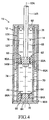
- the shock absorber 16 is a twin-tube shock absorber.
- the cylinder 12 includes an inner cylinder 12X and an outer cylinder 12Y each extending coaxially along the axis 12A.
- the inner cylinder 12X and the outer cylinder 12Y are integrally coupled to each other through intermediation of end caps 62 and 64 respectively at a top end and a bottom end.
- the rod part 14R of the piston 14 passes through the end cap 62 and extends to the outside of the cylinder 12.
- the end cap 64 closes the bottom end of the cylinder 12.
- a base valve assembly 66 is arranged close to the end cap 64, and is fixed to the inner cylinder 12X.
- a main body part 14M of the piston 14 is closely fitted to the inner cylinder 12X so as to be reciprocally movable along the axis 12A.
- the main body part 14M cooperates with the inner cylinder 12X and the end cap 62 to form an upper cylinder chamber 68, and cooperates with the inner cylinder 12X and the base valve assembly 66 to form a lower cylinder chamber 70.
- the base valve assembly 66 forms a base valve chamber 72 between the base valve assembly 66 and the end cap 64.
- the base valve chamber 72 communicates with an annular chamber 74 between the inner cylinder 12X and the outer cylinder 12Y.
- a damping force generation valve 80 for an expansion stroke and a damping force generation valve 82 for a contraction stroke are provided.
- the damping force generation valve 80 for an expansion stroke has an orifice 80A, thereby allowing only a flow of the oil 76 from the upper cylinder chamber 68 toward the lower cylinder chamber 70.
- a damping force in the expansion stroke is generated due to a flow resistance at the time of passage of the oil 76 through the orifice 80A.
- the damping force generation valve 82 for a contraction stroke has an orifice 82A, thereby allowing only a flow of the oil 76 from the lower cylinder chamber 70 toward the upper cylinder chamber 68.
- a damping force in the contraction stroke is generated due to a flow resistance at the time of passage of the oil 76 through the orifice 82A.
- a damping force generation valve 84 for an expansion stroke and a damping force generation valve 86 for a contraction stroke are provided.
- the damping force generation valve 84 for an expansion stroke has an orifice 84A, thereby allowing only a flow of the oil 76 from the base valve chamber 72 toward the lower cylinder chamber 70.
- a damping force in the expansion stroke is generated due to a flow resistance at the time of passage of the oil 76 through the orifice 84A.
- the damping force generation valve 86 for a contraction stroke has an orifice 86A, thereby allowing only a flow of the oil 76 from the lower cylinder chamber 70 toward the base valve chamber 72.
- a damping force in the contraction stroke is generated due to a flow resistance at the time of passage of the oil 76 through the orifice 86A.
- self-discharge type charge eliminators 90A and 90B each in a strip shape are fixed by bonding to surfaces of a center portion and a bottom end portion in the longitudinal direction of the outer cylinder 12Y of the cylinder 12 so as to extend in a circumferential direction.
- self-discharge type charge eliminators 90C and 90D each in a strip shape are fixed by bonding to an outer peripheral portion of the spring seat cushion 58 and an outer peripheral portion of the mounting part 60A of the dust boot 60 so as to extend in the circumferential direction.
- a self-discharge type charge eliminator 90E in a strip shape is fixed by bonding to a top surface of the casing 18A of the upper support 18 so as to extend in a direction perpendicular to a radial direction.
- a position of the piston 14 illustrated in FIG. 4 is a position when the vehicle is in a standard load state, and the wheel 28 is not bounding or rebounding (hereinafter referred to as "standard position").
- the self-discharge type charge eliminator 90A is fixed to the surface of the outer cylinder 12Y of the cylinder 12 below a liquid level of the oil 76 in the annular chamber 74 when the piston 14 is at the standard position.
- the self-discharge type charge eliminators 90A to 90E have the same structure. Thus, referring to FIG. 5 for illustrating a cross section of the charge eliminator 90A before the bonding, a description is only given of the charge eliminator 90A.
- the charge eliminator 90A is formed by shearing, into predetermined size and shape, a composite sheet obtained by applying a conductive pressure-sensitive adhesive 94 to a conductive metal foil 92 and attaching a release sheet 96 covering the adhesive 94 to the adhesive 94.
- the charge eliminator 90A is fixed to the member to be diselectrified by removing the release sheet 96 and bonding the metal foil 92 to the member with the adhesive 94.
- a side surface 92A of the metal foil 92 that is, a surface of the metal foil 92 extending in a thickness direction thereof mainly serves as a discharge surface in a diselectrification phenomenon described later. Therefore, it is preferred that the side surface 92A of the metal foil 92 have a large number of convex portions 92B such as minute protruding portions so that the diselectrification phenomenon occurs efficiently. Further, the plurality of convex portions such as the minute protruding portions may be formed on a surface 92C (upper surface of FIG. 5 ) of the metal foil 92 by subjecting the surface 92C to processing of increasing surface roughness.
- the metal foil 92 may be formed of any metal having conductivity, it is preferred that the metal foil 92 be formed of aluminum, gold, silver, copper, or an alloy thereof. In particular, in the case where the charge eliminator is fixed to a metal member as in this embodiment, it is preferred that the metal foil of the charge eliminator have higher conductivity than a metal material forming the metal member. Further, it is preferred that the metal foil 92 have a thickness of from about 50 ⁇ m to about 200 ⁇ m so that the side surface 92A of the metal foil 92 have a thickness large enough to serve as the discharge surface sufficiently, and the metal foil 92 can be flexibly deformed so as to fit a curved surface to which the metal foil 92 is to be fixed.
- a planar shape of the charge eliminator 90A is not limited to a strip-shaped rectangle and may be any shape other than a rectangle, such as a polygon, a circle, or an oval. It is preferred that the charge eliminator 90A have a shape that can be sheared without leaving a portion to be discarded, for example, a rectangle, a square, a rhomboid, or a hexagon. Further, the size of the charge eliminator 90A may be appropriately set in accordance with a region to which the charge eliminator 90A is applied.
- a short side may be from about several millimeters to about more than 10 mm, and a long side may be from about several tens of millimeters to about 100 mm.
- the charge amount of the electric charge is higher for a resin member than for a metal member, and lower for the oil than for the metal member.
- the charge amounts of the resin spring seat cushion 58 and the resin dust boot 60 are more than the charge amounts of the metal piston 14 and the metal cylinder 12, but the charge amount of the oil 76 is less than the charge amounts of the piston 14 and the cylinder 12.
- a relationship in the electric potential caused by the positive electric charge that is charged to the dust boot 60, the piston 14, the cylinder 12, and the oil 76 is considered to be a relationship indicated by the solid line of FIG. 6 .
- the positive electric charge is generated on and charged to the wheel 28 by the tire 40 repeating the contact and the separation to and from the road surface.
- the cylinder 12 is coupled to the wheel carrier 26 configured to support the wheel 28, and the charge amount of the electric charge to the cylinder 12 is more than that of the piston 14.
- the oil 76 is the lowest in the electric potential among the above-mentioned members and parts.
- the charge amounts of the cylinder 12 and the piston 14 are increased, the electric charge that is charged to those members moves to the oil 76. Consequently, the charge amount of the oil 76 is also increased, thereby increasing the viscosity of the oil 76.
- the viscosity of the oil 76 is increased, the flow resistance at the time of the passage of the oil 76 through the orifice 80A and the like is also increased, and hence the damping force becomes more than an original value, with the result that the ride comfort of the vehicle is degraded. Therefore, the charge amount of the oil 76 is preferably reduced through the diselectrification by the charge eliminator 90A and the like.
- FIG. 7A and FIG. 7B are schematic explanatory views for illustrating a mechanism of diselectrification by the charge eliminator 90A, and the diselectrification by the charge eliminator 90A is assumed to be carried out by the mechanism illustrated in FIG. 7A and FIG. 7B .
- the symbols "+" and “-” respectively denote positive and negative electric charges or ions
- the symbol "0" denotes electric charge of 0, that is, an electrically neutralized state.
- the solid arrows denote the flow of air
- the broken arrows denote the movement of the electric charges or ions.
- Air is charged with positive electric charge.
- the charge amount of the positive electric charge in the resin dust boot 60 is excessively increased, air is separated into positive air ions and negative air ions due to the so-called corona discharge.
- the positive air ions move away from the dust boot 60 due to the repulsive force that acts between the positive air ions and the positive electric charge that is charged to the dust boot 60.
- the negative air ions are attracted to the dust boot 60 due to the Coulomb's force that acts between the negative air ions and the positive electric charge that is charged to the dust boot 60, with the result that the negative air ions move closer to the dust boot 60, and the positive electric charge that is charged to the dust boot 60 moves closer to the negative air ions.
- the diselectrification by the charge eliminator 90A is not limited to a situation in which air flows in one direction as illustrated in FIG. 7A and FIG. 7B .
- the range in a surface direction in which the effect of the above-mentioned diselectrification is exerted is a range of a radius of about 50 mm from a center Pc of the metal foil 92.
- the range in a thickness direction in which the effect of the diselectrification is exerted is a range of from about several millimeters to about more than 10 mm from the bonded surface of the metal foil 92 within the range in the surface direction in which the effect of the diselectrification is exerted. Note that, the range in which the effect of the diselectrification is exerted varies depending on the state of the charge amount of the positive electric charge or the like.
- a portion closest to the center Pc of the metal foil 92 of the charge eliminator 90C falls within the range in the surface direction in which the effect of the diselectrification is exerted along the top surface of the dust boot 60.
- a portion closest to the center Pc of the metal foil 92 of the charge eliminator 90D falls within the range in the surface direction in which the effect of the diselectrification is exerted along the top surface of the dust boot 60.
- the outer cylinder 12Y of the cylinder 12 falls within a range in the thickness direction in which the effect of the diselectrification by the charge eliminators 90A and 90B is exerted.
- the casing 18A of the upper support 18 falls within a range in the thickness direction in which the effect of the diselectrification by the charge eliminator 90E is exerted.
- the positive electric charge that is charged to the dust boot 60 is reduced through the diselectrification by the charge eliminator 90D, and the electric potential of the dust boot 60 is thus reduced.
- the positive electric charge that is charged to the piston 14 moves to the dust boot 60 to be reduced, and the electric potential of the piston 14 is thus reduced.
- the electric potential of the piston 14 is reduced also through the diselectrification by the charge eliminators 90C and 90E, which respectively reduce the electric potential of the spring seat cushion 58 and the upper spring seat 52, resulting in reduction in the electric potential of the casing 18A of the upper support 18.
- the positive electric charge that is charged to the outer cylinder 12Y is reduced through the diselectrification by the charge eliminators 90A and 90B, which reduces the positive electric charge to the entire cylinder 12, resulting in reduction in the electric potential of the cylinder 12.
- the positive electric charge that is charged to the oil 76 in contact with the cylinder 12 and the piston 14 of the shock absorber 16 can be moved to the cylinder 12 and the piston 14, thereby being capable of reducing the charge amount of the electric charge to the oil 76.
- the shock absorber 16 expands and contracts, the piston 14 is displaced with respect to the cylinder 12 so that the oil 76 is agitated, and hence the reduction in the positive electric charge is carried out substantially over the entire oil 76.
- the positive electric charge can be prevented from being excessively charged to the oil 76, thereby being capable of preventing such a state that the viscosity of the oil 76 is excessively increased by the excessive charging of the electric charge to generate an excessively large damping force of the shock absorber 16.
- the self-discharge type charge eliminator 90A is fixed to the surface of the outer cylinder 12Y of the cylinder 12 below the liquid level of the oil 76 in the annular chamber 74 when the piston 14 is at the standard position.
- the charge amount of the oil 76 in the annular chamber 74 can efficiently be reduced through the diselectrification for the outer cylinder 12Y.
- the charge eliminator 90A may partially or entirely be positioned above the liquid level of the oil 76 in the annular chamber 74 when the piston 14 is at the standard position.
- the self-discharge type charge eliminator 90B is fixed to the surface of the bottom end portion of the outer cylinder 12Y.
- the charge amount of the inner cylinder 12X can efficiently be reduced via the end cap 64 through the diselectrification for the bottom end portion of the outer cylinder 12Y by the charge eliminator 90B.
- the following effect was able to be verified through an experiment conducted on an actual vehicle by the inventors of the present invention. That is, when the self-discharge type charge eliminators 90A to 90E were not provided, the electric potential of the oil 76 in the inner cylinder 12X was increased to about several hundreds of volts to about one thousand volts. In contrast, according to the configuration of the first embodiment, the electric potential of the oil 76 in the inner cylinder 12X was increased only to about several tens of volts, and appropriate viscosity of the oil 76 was thus able to be secured.
- FIG. 8 is a partial cross sectional view for illustrating a main part of a damping force generation device 10 according to a second embodiment of the present invention applied to the MacPherson strut front suspension when viewed from the rear of the vehicle.
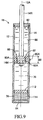
- FIG. 9 is a cross sectional view for illustrating an overview of a mono-tube shock absorber illustrated in FIG. 8 . Note that, in FIG. 8 and FIG. 9 , members corresponding to the members illustrated in FIG. 1 to FIG. 4 are denoted by the same reference symbols as those placed on FIG. 1 to FIG. 4 .
- the shock absorber 16 is an input separation type shock absorber.
- the upper support 18 includes an inner tubular member 18B, an outer tubular member 18C, and a rubber bush 18D filled between the inner tubular member 18B and the outer tubular member 18C.
- a stopper ring 100 is fitted to a distal end of the rod part 14R under a state in which the stopper ring 100 abuts against the shoulder part 14S.
- the inner tubular member 18B is supported under a state in which the inner tubular member 18B is sandwiched between the stopper ring 100 and a nut 102 threadedly engaging with the distal end of the rod part 14R.
- the upper support 18 is coupled to the distal end of the rod part 14R.
- the outer tubular member 18C abuts against the vehicle body 22 at a flange part 18F, and is coupled to the vehicle body 22 at the flange part 18F with bolts 104 and nuts 106 threadedly engaging with the bolts 104.
- a bound stopper 108 is arranged below the outer tubular member 18C.
- the bound stopper 108 includes a rubber main body 108A and a metal support body 108B configured to integrally support a top end of the main body 108A.
- the support body 108B is joined to a bottom surface of the outer tubular member 18C by welding or the like.
- At least one of the outer tubular member 18C or the support body 108B is in contact with the stopper ring 100 or the rod part 14R at a part of an inner peripheral portion directly or through intermediation of a conductive elastic member so as to allow the movement of the electric charge.
- the dust boot 60 according to the second embodiment is also made of a resin.
- a spring seat cushion 60A substantially in an annular plate shape is integrally formed on a top end of the dust boot 60.
- the spring seat cushion 60A abuts against a bottom surface of the flange part 18F of the outer tubular member 18C.
- the flange part 18F of the outer tubular member 18C functions similarly to the upper spring seat 52 according to the first embodiment.
- the spring seat cushion 60A functions similarly to the spring seat cushion 58 according to the first embodiment.
- a rubber lower spring seat cushion 110 is arranged on the lower spring seat 54.
- the spring seat cushion 60A and the lower spring seat cushion 110 are supported by a spring force of the compression coil spring 56 in such a state that the spring seat cushion 60A and the lower spring seat cushion 110 are pressed respectively against the bottom surface of the flange part 18F of the outer tubular member 18C and a top surface of the lower spring seat 54.
- the damping force generated by the shock absorber 16 is transmitted from the rod part 14R to the vehicle body 22 via the inner tubular member 18B, the rubber bush 18D, and the outer tubular member 18C.
- the spring force of the compression coil spring 56 is transmitted to the vehicle body 22 via the spring seat cushion 60A and the flange part 18F of the outer tubular member 18C.
- the input of the spring force to the vehicle body 22 is separated from the input of the damping force to the vehicle body 22.
- the shock absorber 16 is the mono-tube shock absorber.
- a free piston 112 is arranged between the main body part 14M of the piston 14 and the end cap 64 in the cylinder 12.
- the free piston 112 can be displaced with respect to the cylinder 12 along the axis 12A.
- the free piston 112 cooperates with the main body part 14M to form the lower cylinder chamber 70, and cooperates with the end cap 64 to form a gas chamber 114.
- the gas 78 such as nitrogen is sealed in the gas chamber 114.
- the damping force generation valve 80 for an expansion stroke and the damping force generation valve 82 for a contraction stroke are provided in the main body part 14M of the piston 14, the damping force generation valve 80 for an expansion stroke and the damping force generation valve 82 for a contraction stroke are provided.
- the damping force generation valves 80 and 82 are constructed similarly to the damping force generation valves 80 and 82 according to the first embodiment, and similarly generate the damping forces.
- the self-discharge type charge eliminator 90A in the strip shape is fixed by bonding to the surface of the center portion in the longitudinal direction of the cylinder 12 so as to extend in the circumferential direction. However, the self-discharge type charge eliminator is not fixed to the surface of the bottom end portion of the cylinder 12.
- the piston 14 is illustrated at the position when the vehicle is in the standard load state, namely at the standard position.
- the self-discharge type charge eliminator 90A according to this embodiment is fixed to the surface of the cylinder 12 within a predetermined range 88 corresponding to a range in the direction along the axis 12, in which the main body part 14M exists when the piston 14 is at the standard position.
- the self-discharge type charge eliminator 90C in the strip shape is fixed by bonding to a cylindrical outer surface of the spring seat cushion 60A so as to extend in the circumferential direction.
- the self-discharge type charge eliminator 90E in the strip shape is fixed by bonding to the top surface of the outer tubular member 18C of the upper support 18 configured to support the top end of the rod part 14R of the piston 14.
- a portion closest to a center of the metal foil of the charge eliminator 90C falls within a range in the surface direction in which the effect of the diselectrification by the charge eliminator 90C is exerted.
- the cylinder 12 falls within a range in the thickness direction in which the effect of the diselectrification by the charge eliminator 90A is exerted.
- the outer tubular member 18C of the upper support 18 falls within a range in the thickness direction in which the effect of the diselectrification by the charge eliminators 90E is exerted.
- the positive electric charge that is charged to the spring seat cushion 60A of the dust boot 60 is reduced through the diselectrification by the charge eliminator 90C, and the electric potential of the spring seat cushion 60A is thus reduced.
- the positive electric charge that is charged to the piston 14 moves to the dust boot 60 via the outer tubular member 18C to be reduced, and the electric potential of the piston 14 is thus reduced.
- the electric potential of the piston 14 is reduced also through the diselectrification by the charge eliminator 90E, which reduces the electric potential of the outer tubular member 18C of the upper support 18.
- the positive electric charge that is charged to the cylinder 12 is reduced through the diselectrification by the charge eliminator 90A, resulting in reduction in the electric potential of the cylinder 12.
- the positive electric charge that is charged to the oil 76 in contact with the cylinder 12 and the piston 14 can be moved to the cylinder 12 and the piston 14, thereby being capable of reducing the charge amount of the electric charge to the oil 76.
- the positive electric charge can be prevented from being excessively charged to the oil 76, thereby being capable of preventing such a state that the viscosity of the oil 76 is excessively increased by the excessive charging of the electric charge to generate an excessively large damping force of the shock absorber 16.
- the self-discharge type charge eliminator 90A is fixed to the surface of the cylinder 12 within the predetermined range 88.
- the electric charge to the cylinder 12 within the predetermined range 88 can efficiently be reduced, thereby being capable of efficiently reducing the charge amount of the oil 76 around a region in which the main body part 14M exists when the piston 14 is at the standard position.
- the charge eliminator 90A is fixed to the surface of the cylinder 12 within the predetermined range 88, but the charge eliminator 90A may partially or entirely be positioned outside the predetermined range 88. Also in this case, the charge amount of the oil 76 in the cylinder 12 can be reduced by reducing the electric charge to the cylinder 12.
- the following effect was able to be verified through an experiment conducted on an actual vehicle by the inventors of the present invention. That is, when the self-discharge type charge eliminators 90A, 90C, and 90E were not provided, the electric potential of the oil 76 in the cylinder 12 was increased to about several hundreds of volts to about one thousand volts. In contrast, according to the configuration of the second embodiment, the electric potential of the oil 76 was increased only to about several tens of volts, and appropriate viscosity of the oil 76 was thus able to be secured.
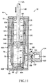
- FIG. 10 and FIG. 11 are enlarged cross sectional views for illustrating an overview of a shock absorber 16 in a damping force generation device 10 according to a third embodiment of the present invention constructed as a twin-tube variable damping force shock absorber.
- FIG. 10 is a view for illustrating the expansion stroke
- FIG. 11 is a view for illustrating the contraction stroke.
- the shock absorber 16 according to the third embodiment is constructed as a so-called uniflow type variable damping force shock absorber.
- a metal intermediate cylinder 12M extending along the axis 12A coaxially with the inner cylinder 12X and the outer cylinder 12Y is arranged.
- the intermediate cylinder 12M is radially separated from the inner cylinder 12X and the outer cylinder 12Y, and is fixed to the inner cylinder 12X by welding or the like at a top end and a bottom end, to thereby form an annular space 120 between the intermediate cylinder 12M and the inner cylinder 12X.
- a top end portion of the annular space 120 is connected to the upper cylinder chamber 68 through a communication hole 121 formed in the inner cylinder 12X.
- a metal conduit 122 extending perpendicularly to the axis 12A is fixed by welding or the like to the intermediate cylinder 12M and the outer cylinder 12Y.
- the conduit 122 communicates with the annular space 120 at one end, and is connected to one end of an internal passage 126 formed inside an effective passage cross sectional area changing device 124 at another end.
- the internal passage 126 communicates with the annular chamber 74 at another end, and has a variable orifice 128 between the one end and the another end.
- the annular space 120, the conduit 122, and the internal passage 126 form a bypass passage 130 connecting the upper cylinder chamber 68 in which the rod part 14R of the piston 14 exists and the annular chamber 74 serving as a reservoir chamber, and having the variable orifice 128 in the course of the bypass passage 130.
- the bypass passage 130 allows only a flow of the oil 76 from the annular space 120 toward the annular chamber 74.
- a housing 132 of the effective passage cross sectional area changing device 124 is made of a metal, and is formed into a substantially columnar shape extending perpendicularly to the axis 12A.
- the housing 132 is fixed to the outer cylinder 12Y by welding or the like.
- an electromagnetic actuator 134 is accommodated in the housing 132.
- the electromagnetic actuator 134 is controlled by an electronic control device (not shown) and drives a valve element (not shown) of the variable orifice 128, to thereby change an effective passage cross sectional area of the variable orifice 128.
- the effective passage cross sectional area changing device 124 is configured such that the electric charge can move from the oil 76 serving as the working liquid passing through the bypass passage 130 to the housing 132.
- the effective passage cross sectional area changing device 124 may have an arbitrary structure as long as the effective passage cross sectional area changing device 124 has the variable orifice 128 formed in the course of the bypass passage 130 and an effective passage cross sectional area of the variable orifice 128 can be changed by control.
- the effective passage cross sectional area changing device 124 refer to, for example, Japanese Patent Application Laid-open No. 2007-225111 , Japanese Patent Application Laid-open No. Hei 11-30265 , and Japanese Patent Application Laid-open No. Hei 6-33969 if necessary.
- the damping force generation valve 82 for a contraction stroke is provided, but the damping force generation valve 80 for an expansion stroke is not provided.
- the damping force generation valve 84 for an expansion stroke is provided, but the damping force generation valve 86 for a contraction stroke is not provided.
- the oil 76 in the upper cylinder chamber 68 moves to the annular chamber 74 through the bypass passage 130. Further, the oil 76 moves to the lower cylinder chamber 70 through the base valve chamber 72 and the damping force generation valve 84 for an expansion stroke of the base valve assembly 66.
- a flow resistance at the time of the passage of the oil 76 through the variable orifice 128 formed in the bypass passage 130, and a flow resistance at the time of the passage of the oil 76 through the damping force generation valve 84 generate the damping force in the expansion stroke.
- variable orifice 108 functions as the damping force generation valve common to the expansion stroke and the contraction stroke.
- the effective passage cross sectional area of the variable orifice 128 is controlled by the electromagnetic actuator 134, to thereby change the damping forces in the expansion stroke and the contraction stroke.
- the self-discharge type charge eliminators 90A and 90B each in the strip shape are fixed by bonding to the surfaces of the center portion and the bottom end portion in the longitudinal direction of the outer cylinder 12Y of the cylinder 12 so as to extend in the circumferential direction.
- a self-discharge type charge eliminator 90I in the strip shape is fixed by bonding to a surface of the housing 132 of the effective passage cross sectional area changing device 124 so as to extend in the circumferential direction.
- the self-discharge type charge eliminators each in the strip shape are fixed by bonding to the top surface of the outer tubular member of the upper support configured to support the top end of the rod part 14R of the piston 14 and the like.
- the inner cylinder 12X, the outer cylinder 12Y, and the piston 14 can be diselectrified by the self-discharge type charge eliminator 90A and the like.
- the positive electric charge that is charged to the oil 76 in the shock absorber 16 can be moved to the outer cylinder 12Y, the piston 14, and the like, thereby being capable of reducing the charge amount of the electric charge to the oil 76 in the shock absorber 16.
- the housing 132 of the effective passage cross sectional area changing device 124 is diselectrified by the self-discharge type charge eliminator 90I, and the oil 76 moves from the upper cylinder chamber 68 to the annular chamber 74 through the bypass passage 130 in any of the expansion stroke and the contraction stroke.
- the positive electric charge that is charged to the oil 76 flowing through the bypass passage 130 can be moved to the housing 132 of the effective passage cross sectional area changing device 124, thereby being capable of reducing the charge amount of the electric charge to the oil 76 circulating through the bypass passage 130.
- the damping force of the shock absorber 16 can be effectively prevented from being excessively increased by the electric charge that is charged to the oil 76.
- FIG. 12 is an enlarged cross sectional view for illustrating an overview of a shock absorber 16 in a damping force generation device 10 according to a fourth embodiment of the present invention constructed as a mono-tube variable damping force shock absorber.
- the shock absorber 16 is constructed as the mono-tube variable damping force shock absorber.
- One end of a first conduit 138 is connected to the upper cylinder chamber 68.
- Another end of the first conduit 138 is connected to one end of an internal passage 142 formed in a first effective passage cross sectional area changing device 140.
- Another end of the internal passage 142 is connected to the lower cylinder chamber 70.
- a first variable orifice 144 and a first check valve 146 are provided between the one end and the another end of the internal passage 142.
- the check valve 146 allows the oil 76 to move from the upper cylinder chamber 68 to the lower cylinder chamber 70, but inhibits the oil 76 from moving from the lower cylinder chamber 70 to the upper cylinder chamber 68.
- a second conduit 148 is connected to the upper cylinder chamber 68. Another end of the second conduit 148 is connected to one end of an internal passage 152 formed in a second effective passage cross sectional area changing device 150. Another end of the internal passage 152 is connected to the lower cylinder chamber 70. Between the one end and the another end of the internal passage 152, a second variable orifice 154 and a second check valve 156 are provided. The check valve 156 allows the oil 76 to move from the lower cylinder chamber 70 to the upper cylinder chamber 68 through the internal passage 152, but inhibits the oil 76 from moving from the upper cylinder chamber 68 to the lower cylinder chamber 70 through the internal passage 152.
- the first conduit 138 and the internal passage 142 form a first bypass passage 158 connecting the upper cylinder chamber 68 and the lower cylinder chamber 70, and having the first variable orifice 144 and the first check valve 146 in the course of the first bypass passage 158.
- the second conduit 148 and the internal passage 152 form a second bypass passage 160 connecting the upper cylinder chamber 68 and the lower cylinder chamber 70, and having the second variable orifice 154 and the second check valve 156 in the course of the second bypass passage 160.
- a housing 162 of the first effective passage cross sectional area changing device 140 is made of a metal, and is formed into a substantially columnar shape extending perpendicularly to the axis 12A.
- the housing 1642 is fixed to the cylinder 12 by welding or the like.
- an electromagnetic actuator 164 is accommodated in the housing 162.
- the electromagnetic actuator 164 is controlled by an electronic control device (not shown) and drives a valve element (not shown) of the first variable orifice 144, to thereby change an effective passage cross sectional area of the first variable orifice 144.
- the first effective passage cross sectional area changing device 1420 is configured such that the electric charge can move from the oil 76 passing through the first bypass passage 158 to the housing 162.
- a housing 166 of the second effective passage cross sectional area changing device 150 is made of a metal, and is formed into a substantially columnar shape extending perpendicularly to the axis 12A.
- the housing 166 is fixed to the cylinder 12 by welding or the like.
- an electromagnetic actuator 168 is accommodated in the housing 166.
- the electromagnetic actuator 168 is controlled by an electronic control device (not shown) and drives a valve element (not shown) of the second variable orifice 154, to thereby change an effective passage cross sectional area of the second variable orifice 154.
- the second effective passage cross sectional area changing device 150 is configured such that the electric charge can move from the oil 76 passing through the second bypass passage 160 to the housing 166.
- the oil 76 in the upper cylinder chamber 68 moves to the lower cylinder chamber 70 through the damping force generation valve 80 for an expansion stroke, which is provided in the main body part 14M of the piston 14. Further, the oil 76 in the upper cylinder chamber 68 moves to the lower cylinder chamber 70 through the first bypass passage 158.
- a flow resistance at the time of the passage of the oil 76 through the damping force generation valve 80, and a flow resistance at the time of the passage of the oil 76 through the first variable orifice 144 formed in the first bypass passage 158 generate the damping force in the expansion stroke.
- the damping force in the expansion stroke is changed by the electromagnetic actuator 164 that controls the effective passage cross sectional area of the first variable orifice 144.
- the oil 76 first passes through the damping force generation valve 80.
- the oil 76 first passes through the first variable orifice 144.
- the oil 76 in the lower cylinder chamber 70 moves to the upper cylinder chamber 68 through the damping force generation valve 82 for a contraction stroke, which is provided in the main body part 14M of the piston 14. Further, the oil 76 in the lower cylinder chamber 70 moves to the upper cylinder chamber 68 through the second bypass passage 160.
- a flow resistance at the time of the passage of the oil 76 through the damping force generation valve 82, and a flow resistance at the time of the passage of the oil 76 through the second variable orifice 154 formed in the second bypass passage 160 generate the damping force in the contraction stroke.
- the damping force in the contraction stroke is changed by the electromagnetic actuator 168 that controls the effective passage cross sectional area of the second variable orifice 154.
- the oil 76 first passes through the damping force generation valve 82.
- the oil 76 first passes through the second variable orifice 154.
- the self-discharge type charge eliminator 90A in the strip shape is fixed by bonding to the surface of the center portion in the longitudinal direction of the outer cylinder 12Y of the cylinder 12 so as to extend in the circumferential direction.
- Self-discharge type charge eliminators 90J and 90K each in the strip shape are fixed by bonding to surfaces of the housings 162 and 166 of the first and second effective passage cross sectional area changing devices 140 and 150 so as to extend in the circumferential direction.
- the self-discharge type charge eliminators each in the strip shape are fixed by bonding to the top surface of the outer tubular member of the upper support configured to support the top end of the rod part 14R of the piston 14 and the like.
- the cylinder 12 and the piston 14 can be diselectrified by the self-discharge type charge eliminator 90A and the like.
- the positive electric charge that is charged to the oil 76 in the upper cylinder chamber 68 and the lower cylinder chamber 70 can be moved to the cylinder 12, the piston 14, and the like, thereby being capable of reducing the charge amount of the electric charge to the oil 76 in the upper cylinder chamber 68 and the lower cylinder chamber 70.
- the housing 162 of the first effective passage cross sectional area changing device 140 is diselectrified by the self-discharge type charge eliminator 90J
- the housing 166 of the second effective passage cross sectional area changing device 150 is diselectrified by the self-discharge type charge eliminator 90K.
- the damping force of the shock absorber 16 can be effectively prevented from being excessively increased by the electric charge that is charged to the oil 76.
- the charge eliminator 90A and the like are so-called ion-separation non-grounded self-discharge type charge eliminators.
- the charge eliminator 90A and the like separate the air into positive air ions and negative air ions through corona discharge, and carry out the diselectrification through electrical neutralization between the positive electric charge that is charged to the components of the damping force generation device 10 and the negative air ions, thereby requiring no wires for electrical grounding.
- the electrostatic eliminator disclosed in Japanese Patent Application Laid-open No. 2009-181694 is used, the structure for the diselectrification in the damping force generation device 10 can be simplified, and a cost required for attaining the diselectrification can be greatly reduced.
- the charge amount of the electric charge to the cylinder 12 can be reduced by the charge eliminator 90A and the like, and the charge amount of the electric charge to the piston 14 can be reduced by the charge eliminator 90C and the like.
- the charge amount of the electric charge to the oil 76 can be effectively reduced.
- the damping force of the shock absorber 16 can be effectively prevented from being excessively increased.
- the charge eliminators 90C and 90D are fixed respectively to the outer peripheral portion of the resin spring seat cushion 58 and the outer peripheral portion of the mounting part 60A of the resin dust boot 60.
- the charge eliminator 90C is fixed to the outer peripheral portion of the spring seat cushion 60A of the resin dust boot 60.
- the amount of the electric charge that is charged to the resin members is more than the amount of the electric charge that is charged to the metal members, and hence, compared to the case where the charge eliminators are fixed to the metal members, the diselectrification for the members can be effectively carried out.
- the charge amount of the electric charge to the piston 14 can efficiently be reduced.
- the charge eliminator is directly fixed by bonding to those members.
- a special member need not be added in order to fix the charge eliminator, and hence the charge amount of the electric charge to the oil 76 in the shock absorber 16 can be reduced without causing increase in complexity of the structure and cost of the damping force generation device 10.
- the charge amount of the electric charge to the oil 76 can be reduced by fixing the self-discharge type charge eliminator in the same way as in the first and second embodiments.
- the self-discharge type charge eliminator 90I is provided on the surface of the effective passage cross sectional area changing device 124 configured to change the effective passage cross sectional area such as that of the variable orifice 128 formed in the bypass passage 130.
- each of the charge eliminator 90A and the like is in the form of the tape obtained by applying the conductive pressure-sensitive adhesive 94 to the conductive metal foil 92, and the charge eliminator is fixed to the member to be diselectrified by the bonding of the metal foil 92 to the member with the adhesive 94.
- the metal foil for the diselectrification can easily be fixed by the bonding to the surface of the member to be diselectrified.
- a layer of the adhesive has the conductivity, and hence, compared to the case where the layer of the adhesive does not have the conductivity, the electric charge can efficiently be moved from the specific member to the metal foil, thereby being capable of enhancing the effect of the diselectrification.
- the layer of the adhesive need not have the conductivity.
- the self-discharge type charge eliminator 90A and the like are fixed to the members constructing the shock absorber 16 and the auxiliary members connected to the shock absorber, but any one of the charge eliminators may be omitted.
- the self-discharge type charge eliminators 90A, 90C, and 90E are fixed to the members constructing the shock absorber 16 and the auxiliary members connected to the shock absorber, but any one of the charge eliminators 90A, 90C, and 90E may be omitted.
- the charge eliminators 90A and the like according to the above-mentioned respective embodiments are fixed at the specific positions such as a position on the rear side of the vehicle with respect to the axis 12A of the shock absorber 16.
- the position about the axis 12A to which the charge eliminator is fixed need not be the position according to the above-mentioned embodiments.
- the number of the charge eliminators to be fixed and the extension directions of the charge eliminators are not limited to the number and the extension directions of each of the above-mentioned embodiments.
- a plurality of charge eliminators 90A may be fixed to the cylinder 12 below the lower spring seat 54, and the charge eliminators 90A may be fixed so as to extend along the axis 12A.
- self-discharge type charge eliminators 90F may be fixed to the bracket 24.
- self-discharge type charge eliminators 90G may be fixed to the surface of the outer cylinder 12Y or the surface of the end cap 62 close to the top end of the cylinder 12.
- the top end of the outer cylinder 12Y or the end cap 62 can be diselectrified more efficiently than in the first embodiment, thereby being capable of efficiently reducing the charge amount of the electric charge to the inner cylinder 12X and the oil 76 inside the inner cylinder 12X.
- a self-discharge type charge eliminator 90H may be fixed to an outer peripheral portion of the upper spring seat 52.
- the shock absorber 16 according to the first embodiment is the twin-tube shock absorber, but the shock absorber 16 may be a mono-tube shock absorber.
- the shock absorber 16 according to the second embodiment is the mono-tube shock absorber, but the shock absorber 16 may be a twin-tube shock absorber.
- the effective passage cross sectional areas of the first variable orifice 124 and the second variable orifice 134 are controlled by the corresponding electromagnetic actuators 144 and 148.
- the first variable orifice 124 and the second variable orifice 134 are formed by a single spool valve, and the spool valve is driven by a single electromagnetic actuator.
- the number of the effective passage cross sectional area changing devices only needs to be one. The number of components can thus be reduced, and the number of self-discharge type charge eliminators can also be reduced compared to the above-mentioned fourth embodiment.
- the suspension is the MacPherson strut suspension.
- the suspension to which the damping force generation device according to the present invention is applied may be other arbitrary types of suspension such as a double wishbone suspension, a trailing arm suspension, and an axle suspension.
Landscapes
- Engineering & Computer Science (AREA)
- General Engineering & Computer Science (AREA)
- Mechanical Engineering (AREA)
- Health & Medical Sciences (AREA)
- General Health & Medical Sciences (AREA)
- Toxicology (AREA)
- Vehicle Body Suspensions (AREA)
- Fluid-Damping Devices (AREA)
Abstract
Description
- The present invention relates to a damping force generation device for a vehicle, and more particularly, to a damping force generation device including a shock absorber.
- When a vehicle such as an automobile travels, static electricity is generated in the vehicle due to the flow of air in a state in which the air is brought into friction contact with the vehicle. Static electricity is also generated when each portion of a tire is repeatedly brought into contact with a road surface and separated therefrom along with the rotation of a wheel, when components in an engine, a brake device, or the like move relatively under a contact state, and the like.
- The vehicle is substantially electrically insulated from the ground due to a tire having low conductivity, and hence electric charge (in general, positive electric charge) is charged to a vehicle body or the like when static electricity is generated in the vehicle. Radio noise is liable to be generated when the electric charge is charged to the vehicle body or the like. Therefore, a structure for reducing electric charge that is charged to a vehicle through the passage of an electric current has been investigated hitherto, and various structures have been proposed.
- For example, in Japanese Patent Application Laid-open No.
2009-181694 - The related-art electrostatic eliminator as disclosed in Japanese Patent Application Laid-open No.
2009-181694 - Incidentally, the vehicle includes damping force generation devices configured to damp vibrations of the vehicle body. Each of the damping force generation devices includes a shock absorber having a cylinder and a piston fitted to the cylinder in a reciprocally movable manner. The shock absorber is coupled to a sprung member and an unsprung member of the vehicle at a rod part of the piston and the cylinder, respectively, and generates the damping force due to a flow resistance when oil passes through orifices formed in the piston along with relative displacement between the sprung member and the unsprung member.
- Experimental research conducted by the inventors of the present invention has revealed that an adverse effect on the vehicle exerted by electric charge that is charged to the vehicle is not limited to the increase in the risk of generation of radio noise. In other words, when the electric charge is charged to the vehicle, the electric charge is also charged to the oil in the shock absorbers. As a result, the viscosity of the oil is increased so that damping forces are liable to become excessive.
- The related-art electrostatic eliminator as disclosed in Japanese Patent Application Laid-open No.
2009-181694 - The present invention has been made in view of the above-mentioned phenomenon and the cause of the phenomenon, which have not been recognized hitherto. It is a primary object of the present invention to prevent electric charge from being excessively charged to oil in a shock absorber, thereby preventing viscosity of the oil from being increased by the charging of the electric charge to generate an excessive damping force.
- According to one embodiment of the present invention, there is provided a damping force generation device for a vehicle, including a shock absorber including: a cylinder; and a piston fitted into the cylinder in a reciprocally movable manner to form two cylinder chambers in cooperation with the cylinder, the shock absorber being coupleable to one of a sprung member and an unsprung member of the vehicle at a rod part of the piston, and to another one of the sprung member and the unsprung member at the cylinder, the sprung member being kept substantially electrically insulated from a road, and the shock absorber being configured to generate a damping force due to a flow resistance when a working liquid passes through an orifice formed in a main body part of the piston to move between the two cylinder chambers along with relative displacement between the sprung member and the unsprung member.
- The damping force generation device for a vehicle further includes a self-discharge type charge eliminator provided on a surface of a specific member being at least one of a member constructing the shock absorber or an auxiliary member connected to the shock absorber. The self-discharge type charge eliminator is an air-ion conversion self-discharge type charge eliminator configured to reduce a charge amount of positive electric charge, which is charged to the specific member, through diselectrification carried out by changing air around the air-ion conversion self-discharge type charge eliminator into negative air ions depending on the charge amount of the specific member, and by causing the negative air ions to be attracted to the positive electric charge of the specific member to neutralize the positive electric charge, to thereby reduce a charge amount of the working liquid.
- A reason for the charging of the electric charge to the working liquid such as the oil in the shock absorber when the electric charge is charged to the vehicle body and the like, and a cause of the increase in the viscosity of the working fluid when the electric charge is charged to the working liquid are not necessarily apparent, but major reason and cause are considered as follows. The shock absorber is coupled to one of and another one of the sprung member and the unsprung member of the vehicle at the rod part of the piston and the cylinder, respectively. Thus, when the electric charge is charged to the vehicle body or the like, the electric charge moves to the piston and the cylinder through the sprung member and the unsprung member, respectively. When the amount of the electric charge that is charged to the piston and the cylinder is increased, a part of the electric charge moves to the working liquid in the shock absorber. As a result, the electric charge is charged to the working liquid. It is presumed that when the electric charge is charged to the working liquid, a degree of freedom of molecules of the working liquid is reduced, which increases the viscosity of the working liquid.
- According to the above-mentioned configuration, the damping force generation device for a vehicle includes the self-discharge type charge eliminator provided on the surface of the specific member being at least one of the member constructing the shock absorber or the auxiliary member connected to the shock absorber. The charge eliminator reduces the charge amount of the specific member through diselectrification carried out by changing the air around the charge eliminator into negative air ions, and by causing the negative air ions to be attracted to the positive electric charge of the specific member to neutralize the positive electric charge. Thus, the charge amount of the working liquid is reduced through the movement of the electric charge that is charged to the working liquid in the shock absorber to the specific member, thereby being capable of preventing such a state that the viscosity of the working liquid is increased by the excessive charging of the electric charge to generate the excessive damping force.
- Note that, according to the above-mentioned configuration, an electrostatic eliminator having a complicated structure may be omitted, and hence the electrostatic eliminator need not be connected to a minus terminal of a battery or a vehicle body through conductive wires. Further, the self-discharge type charge eliminator may be, for example, a thin conductive body capable of carrying out so-called self-discharge through use of electric charge that is charged to the specific member, and hence a large space as in the case of installing the electrostatic eliminator is not required.
- According to one embodiment of the present invention, the specific member is a dust boot made of a resin as the auxiliary member connected to the rod part, the self-discharge type charge eliminator is provided on a surface of the dust boot, and the rod part and the dust boot are connected to each other so that the positive electric charge is movable from the rod part to the dust boot.
- According to the above-mentioned embodiment, the self-discharge type charge eliminator is provided on the surface of the dust boot. The dust boot is made of a resin, to which the electric charge is charged more easily than to a metal. Further, the rod part and the dust boot are connected to each other so that the electric charge is movable from the rod part to the dust boot. Thus, the dust boot is diselectrified by the self-discharge type charge eliminator so that the electric charge that is charged to the piston moves to the dust boot via the rod part, and the electric charge that is charged to the working liquid thus moves to the piston. Thus, the charge amount of the working liquid can be reduced, thereby being capable of preventing such a state that the viscosity of the working liquid is increased by the excessive charging of the electric charge to generate the excessive damping force.
- According to one embodiment of the present invention, the shock absorber is a twin-tube shock absorber including: an inner cylinder to which the piston is fitted; and an outer cylinder surrounding the inner cylinder, the specific member is the outer cylinder, and the self-discharge type charge eliminator is provided on a surface of the outer cylinder below a liquid level of the working liquid between the inner cylinder and the outer cylinder when the vehicle is in a standard load state.
- According to the above-mentioned embodiment, in the twin-tube shock absorber, the self-discharge type charge eliminator is provided on the surface of the outer cylinder below the liquid level of the working liquid between the inner cylinder and the outer cylinder when the vehicle is in the standard load state. Thus, compared to a case where the self-discharge type charge eliminator is provided on the surface of the outer cylinder above the liquid level of the working liquid between the inner cylinder and the outer cylinder, the working liquid between the inner cylinder and the outer cylinder can efficiently be diselectrified. Thus, the inner cylinder can efficiently be diselectrified so that the electric charge that is charged to the working liquid in the inner cylinder can efficiently be moved to the inner cylinder, and the working liquid in the inner cylinder can thus efficiently be diselectrified.
- According to one embodiment of the present invention, the shock absorber is a twin-tube shock absorber including: an inner cylinder to which the piston is fitted; an outer cylinder surrounding the inner cylinder to form a reservoir chamber between the inner cylinder and the outer cylinder; a base valve assembly; and an end cap closing end portions of the inner cylinder and the outer cylinder to define a base valve chamber communicating with the reservoir chamber in cooperation with the base valve assembly, the specific member is at least one of the outer cylinder or the end cap, and the positive electric charge is movable from the inner cylinder to the specific member.
- According to the above-mentioned embodiment, in the twin-tube shock absorber, the self-discharge type charge eliminator is provided on the surface of at least one of the outer cylinder or the end cap, which is the specific member, and the electric charge is movable from the inner cylinder to the specific member. When the specific member is diselectrified by the charge eliminator, the electric charge moves from the inner cylinder to the specific member so that the electric potential of the inner cylinder is reduced. Thus, the electric charge that is charged to the working liquid in the inner cylinder moves to the inner cylinder. Thus, the charge amount of the working liquid in the inner cylinder can be reduced, thereby being capable of preventing such a state that the viscosity of the working liquid is increased by the excessive charging of the electric charge to generate the excessive damping force.
- According to one embodiment of the present invention, the shock absorber is a mono-tube shock absorber, the specific member is the cylinder, and the self-discharge type charge eliminator is provided on a surface of the cylinder so that at least a part of the self-discharge type charge eliminator is positioned within a predetermined range corresponding to a range in a direction of the relative displacement, in which the main body part of the piston exists when the vehicle is in a standard load state.
- According to the above-mentioned embodiment, in the mono-tube shock absorber, the self-discharge type charge eliminator is provided on the surface of the cylinder. Thus, when the cylinder is diselectrified by the charge eliminator, the electric potential of the cylinder is reduced. Consequently, the electric charge that is charged to the working liquid moves to the cylinder. Thus, the charge amount in the working liquid can be reduced, thereby being capable of preventing such a state that the viscosity of the working liquid is increased by the excessive charging of the electric charge to generate the excessive damping force. Further, compared to a case where the self-discharge type charge eliminator is provided on the surface of the cylinder outside the predetermined range, the diselectrification for the working liquid existing around the main body part of the piston in which the orifice is formed can efficiently be carried out.
- According to one embodiment of the present invention, the shock absorber is a variable damping force shock absorber including: a bypass passage for bypassing the main body part of the piston to connect the two cylinder chambers to each other; a variable orifice formed in the bypass passage; and an effective passage cross sectional area changing device configured to change an effective passage cross sectional area of the variable orifice, the variable damping force shock absorber being configured such that, when the piston is displaced with respect to the cylinder, at least a part of the working liquid in one of the two cylinder chambers moves to another one of the two cylinder chambers through the bypass passage, the specific member is the effective passage cross sectional area changing device, and the positive electric charge is movable from the working liquid passing through the bypass passage to the effective passage cross sectional area changing device.
- According to the above-mentioned embodiment, in the variable damping force shock absorber, the self-discharge type charge eliminator is provided on the surface of the effective passage cross sectional area changing device configured to change the effective passage cross sectional area of the variable orifice formed in the bypass passage. Further, the electric charge can move from the working liquid passing through the bypass passage to the effective passage cross sectional area changing device. Thus, the effective passage cross sectional area changing device is diselectrified by the self-discharge type charge eliminator so that the electric charge that is charged to the working liquid moves to the effective passage cross sectional area changing device, and the electric charge that is charged to the working liquid passing through the bypass passage is thus reduced. Thus, it is possible to prevent such a state that the viscosity of the working liquid passing through the variable orifice is increased by the excessive charging of the electric charge to generate the excessive damping force.
- According to one embodiment of the present invention, the self-discharge type charge eliminator includes: a conductive metal foil having a large number of minute protrusions and recesses formed on a side surface on an outer periphery of the conductive metal foil; and a layer of an adhesive applied to one surface of the conductive metal foil, and the self-discharge type charge eliminator is fixed to the specific member by bonding with the layer of the adhesive.
- According to the above-mentioned embodiment, the metal foil for the diselectrification can easily be fixed by the bonding to the surface of the specific member. Further, the metal foil is brought into close contact with the specific member through intermediation of the layer of the adhesive across the entire surface, and hence the electric charge can efficiently be moved from the specific member to the metal foil, thereby being capable of enhancing the effect of the diselectrification.
-
-
FIG. 1 is a schematic view for illustrating a damping force generation device according to a first embodiment of the present invention applied to a MacPherson strut front suspension when viewed from the rear of a vehicle. -
FIG. 2 is a perspective view of the damping force generation device illustrated inFIG. 1 . -
FIG. 3 is an exploded perspective view of the damping force generation device illustrated inFIG. 1 . -
FIG. 4 is an enlarged cross sectional view for illustrating an overview of a twin-tube shock absorber illustrated inFIG. 1 . -
FIG. 5 is an enlarged cross sectional view for illustrating a self-discharge type charge eliminator before bonding. -
FIG. 6 is a chart for illustrating a relationship among electric potentials caused by charging of positive electric charge to a dust boot, a piston, a cylinder, and oil in the shock absorber. -
FIG. 7A and FIG. 7B are schematic explanatory views for illustrating a mechanism of diselectrification by the self-discharge type charge eliminator, in whichFIG. 7A is a cross sectional view, andFIG. 7B is a plan view. -
FIG. 8 is a partial cross sectional view for illustrating a main part of a damping force generation device according to a second embodiment of the present invention applied to the MacPherson strut front suspension when viewed from the rear of the vehicle. -
FIG. 9 is a cross sectional view for illustrating an overview of a mono-tube shock absorber illustrated inFIG. 8 . -
FIG. 10 is an enlarged cross sectional view for illustrating an overview of a shock absorber in an expansion stroke in a damping force generation device according to a third embodiment of the present invention constructed as a twin-tube variable damping force shock absorber. -
FIG. 11 is an enlarged cross sectional view for illustrating an overview of the shock absorber in a contraction stroke in the damping force generation device according to the third embodiment. -
FIG. 12 is an enlarged cross sectional view for illustrating an overview of a shock absorber in a damping force generation device according to a fourth embodiment of the present invention constructed as a mono-tube variable damping force shock absorber. -
FIG. 13 is an exploded perspective view of a damping force generation device according to a modified example. - Now, with reference to the accompanying drawings, preferred embodiments of the present invention are described in detail.
-
FIG. 1 is a schematic view for illustrating a dampingforce generation device 10 according to a first embodiment of the present invention applied to a MacPherson strut front suspension when viewed from the rear of a vehicle.FIG. 2 is a perspective view of the dampingforce generation device 10 illustrated inFIG. 1 .FIG. 3 is an exploded perspective view of the dampingforce generation device 10 illustrated inFIG. 1 . - In
FIG. 1 to FIG. 3 , the dampingforce generation device 10 includes ashock absorber 16 including acylinder 12 and apiston 14. Thepiston 14 is fitted to thecylinder 12 so as to be reciprocally movable with respect to thecylinder 12 along anaxis 12A. Thecylinder 12 and thepiston 14 are made of a metal such as steel. Arod part 14R of thepiston 14 extends upward through a top end of thecylinder 12. Note that, members described below are made of a conductive metal such as steel except for members whose forming materials are particularly described. Metal members including thecylinder 12 and thepiston 14 are coated for increasing durability, and surfaces are covered by non-conductive coating films. - The
shock absorber 16 is coupled to avehicle body 22 serving as a sprung member of avehicle 20 at a top end portion of therod part 14R through intermediation of anupper support 18, and is coupled to awheel carrier 26 serving as an unsprung member of thevehicle 20 through intermediation of abracket 24 fixed to a bottom end portion of thecylinder 12. As widely known, theupper support 18 supports therod part 14R through use of a rubber bush device arranged inside acasing 18A. Thewheel carrier 26 supports aspindle 30 of awheel 28 so as to be rotatable about arotational axis 32 through intermediation of a bearing (not shown). Note that, the bottom end portion of theshock absorber 16 may be coupled to thewheel carrier 26 or a suspension member in a relatively movable manner through intermediation of coupling means such as a rubber bush device (not shown). - In the illustrated embodiment, the
wheel 28 is a steered wheel, and is also a driving wheel. Adrive shaft 36 is coupled to thespindle 30 through intermediation of auniversal joint 34. Thewheel 28 includes awheel member 38 mounted to a flange part of thespindle 30 and atire 40 made of rubber and the like, which is assembled on an outer periphery of thewheel member 38. Thevehicle body 22 is kept substantially electrically insulated from a road R due to atire 40 having low conductivity. Note that, the wheel to which the damping force generation device according to the present invention is applied may be a non-steered wheel or a driven wheel, and may further be a rear wheel. - An outer end of a control arm (lower arm) 42 is coupled to a bottom end portion of the
wheel carrier 26 in a pivotable manner through intermediation of a ball joint 44. In the illustrated embodiment, thecontrol arm 42 is an L-shaped arm having an inner end and a rear end in addition to the outer end. The inner end and the rear end are supported in a swingable manner by brackets (not shown) of the vehicle body respectively through intermediation ofrubber bush devices control arm 42 and a center of theupper support 18 cooperate to define akingpin axis 50. Thus, thewheel 28 is driven about thekingpin axis 50 by a steering device (not shown) through intermediation of a tie rod, thereby being steered. - Although the illustration is omitted, the top end portion of the
rod part 14R of thepiston 14 extends through anupper spring seat 52. As described later referring toFIG. 3 , theupper spring seat 52 is fixed to therod part 14R so as to abut at a top surface against a bottom surface of theupper support 18. Between theupper spring seat 52 and alower spring seat 54 fixed to thecylinder 12, acompression coil spring 56 is elastically mounted as a suspension spring. - As understood from the above description, the damping
force generation device 10 is applied to the MacPherson strut front suspension. Theshock absorber 16, theupper support 18, thecompression coil spring 56, and the like cooperate with one another to construct the MacPherson strut. Thus, when thewheel carrier 26 vertically moves as a result of a bound and a rebound of thewheel 28, thecontrol arm 42 swings in the vertical direction about therubber bush devices shock absorber 16 expands and contracts, and thecompression coil spring 56 elastically deforms. - As illustrated in
FIG. 3 , the top end portion of therod part 14R passes through aspring seat cushion 58 and the top end of adust boot 60 located below theupper spring seat 52. Thespring seat cushion 58 and thedust boot 60 are auxiliary members of theshock absorber 16, which are sandwiched between theupper spring seat 52 and ashoulder part 14S of therod part 14R to be connected to therod part 14R in a fixed manner, and are formed through use of a resin. Thespring seat cushion 58 abuts against a bottom surface of theupper spring seat 52 at a top surface of an outer peripheral portion. - In particular, in the illustrated embodiment, the
dust boot 60 includes acylindrical part 60C extending along thecylinder 12 and therod part 14R around thecylinder 12 and therod part 14R, and a mountingpart 60A in an inverted bowl shape integrally formed with a top end of thecylindrical part 60C. The mountingpart 60A closes the top end of thedust boot 60 except for ahole 60H through which therod part 14R is inserted, and is in close contact with therod part 14R on a wall surface of thehole 60H. Thecylindrical part 60C is formed into a bellows shape so as to allow expansion and contraction, and is compressed and deformed when a compression load along theaxis 12A is applied. - As schematically illustrated in
FIG. 4 , theshock absorber 16 is a twin-tube shock absorber. Thecylinder 12 includes aninner cylinder 12X and anouter cylinder 12Y each extending coaxially along theaxis 12A. Theinner cylinder 12X and theouter cylinder 12Y are integrally coupled to each other through intermediation ofend caps rod part 14R of thepiston 14 passes through theend cap 62 and extends to the outside of thecylinder 12. Theend cap 64 closes the bottom end of thecylinder 12. In theinner cylinder 12X, abase valve assembly 66 is arranged close to theend cap 64, and is fixed to theinner cylinder 12X. - A
main body part 14M of thepiston 14 is closely fitted to theinner cylinder 12X so as to be reciprocally movable along theaxis 12A. Themain body part 14M cooperates with theinner cylinder 12X and theend cap 62 to form anupper cylinder chamber 68, and cooperates with theinner cylinder 12X and thebase valve assembly 66 to form alower cylinder chamber 70. Thebase valve assembly 66 forms abase valve chamber 72 between thebase valve assembly 66 and theend cap 64. Thebase valve chamber 72 communicates with anannular chamber 74 between theinner cylinder 12X and theouter cylinder 12Y. - In the
upper cylinder chamber 68, thelower cylinder chamber 70, thebase valve chamber 72, and theannular chamber 74,oil 76 serving as a working liquid is filled.Gas 78 such as nitrogen is sealed in an upper part of theannular chamber 74. As theshock absorber 16 expands and contracts, a volume of therod part 14R existing in thecylinder 12 changes, and hence thegas 78 in theannular chamber 74 absorbs the change in the volume of therod part 14R existing in thecylinder 12. - In the
main body part 14M of thepiston 14, a dampingforce generation valve 80 for an expansion stroke and a dampingforce generation valve 82 for a contraction stroke are provided. The dampingforce generation valve 80 for an expansion stroke has anorifice 80A, thereby allowing only a flow of theoil 76 from theupper cylinder chamber 68 toward thelower cylinder chamber 70. A damping force in the expansion stroke is generated due to a flow resistance at the time of passage of theoil 76 through theorifice 80A. Similarly, the dampingforce generation valve 82 for a contraction stroke has anorifice 82A, thereby allowing only a flow of theoil 76 from thelower cylinder chamber 70 toward theupper cylinder chamber 68. A damping force in the contraction stroke is generated due to a flow resistance at the time of passage of theoil 76 through theorifice 82A. - Also in the
base valve assembly 66, a dampingforce generation valve 84 for an expansion stroke and a dampingforce generation valve 86 for a contraction stroke are provided. The dampingforce generation valve 84 for an expansion stroke has anorifice 84A, thereby allowing only a flow of theoil 76 from thebase valve chamber 72 toward thelower cylinder chamber 70. A damping force in the expansion stroke is generated due to a flow resistance at the time of passage of theoil 76 through theorifice 84A. Similarly, the dampingforce generation valve 86 for a contraction stroke has anorifice 86A, thereby allowing only a flow of theoil 76 from thelower cylinder chamber 70 toward thebase valve chamber 72. A damping force in the contraction stroke is generated due to a flow resistance at the time of passage of theoil 76 through theorifice 86A. - As illustrated in
FIG. 2 andFIG. 3 , self-dischargetype charge eliminators outer cylinder 12Y of thecylinder 12 so as to extend in a circumferential direction. As illustrated inFIG. 3 , self-dischargetype charge eliminators spring seat cushion 58 and an outer peripheral portion of the mountingpart 60A of thedust boot 60 so as to extend in the circumferential direction. Further, a self-dischargetype charge eliminator 90E in a strip shape is fixed by bonding to a top surface of thecasing 18A of theupper support 18 so as to extend in a direction perpendicular to a radial direction. - Note that, a position of the
piston 14 illustrated inFIG. 4 is a position when the vehicle is in a standard load state, and thewheel 28 is not bounding or rebounding (hereinafter referred to as "standard position"). In the illustrated embodiment, the self-dischargetype charge eliminator 90A is fixed to the surface of theouter cylinder 12Y of thecylinder 12 below a liquid level of theoil 76 in theannular chamber 74 when thepiston 14 is at the standard position. - The self-discharge
type charge eliminators 90A to 90E have the same structure. Thus, referring toFIG. 5 for illustrating a cross section of thecharge eliminator 90A before the bonding, a description is only given of thecharge eliminator 90A. The charge eliminator 90A is formed by shearing, into predetermined size and shape, a composite sheet obtained by applying a conductive pressure-sensitive adhesive 94 to aconductive metal foil 92 and attaching arelease sheet 96 covering the adhesive 94 to the adhesive 94. The charge eliminator 90A is fixed to the member to be diselectrified by removing therelease sheet 96 and bonding themetal foil 92 to the member with the adhesive 94. - As described later in detail, a
side surface 92A of themetal foil 92, that is, a surface of themetal foil 92 extending in a thickness direction thereof mainly serves as a discharge surface in a diselectrification phenomenon described later. Therefore, it is preferred that theside surface 92A of themetal foil 92 have a large number ofconvex portions 92B such as minute protruding portions so that the diselectrification phenomenon occurs efficiently. Further, the plurality of convex portions such as the minute protruding portions may be formed on asurface 92C (upper surface ofFIG. 5 ) of themetal foil 92 by subjecting thesurface 92C to processing of increasing surface roughness. - As described later in detail, although the
metal foil 92 may be formed of any metal having conductivity, it is preferred that themetal foil 92 be formed of aluminum, gold, silver, copper, or an alloy thereof. In particular, in the case where the charge eliminator is fixed to a metal member as in this embodiment, it is preferred that the metal foil of the charge eliminator have higher conductivity than a metal material forming the metal member. Further, it is preferred that themetal foil 92 have a thickness of from about 50 µm to about 200 µm so that theside surface 92A of themetal foil 92 have a thickness large enough to serve as the discharge surface sufficiently, and themetal foil 92 can be flexibly deformed so as to fit a curved surface to which themetal foil 92 is to be fixed. - Note that, a planar shape of the
charge eliminator 90A is not limited to a strip-shaped rectangle and may be any shape other than a rectangle, such as a polygon, a circle, or an oval. It is preferred that thecharge eliminator 90A have a shape that can be sheared without leaving a portion to be discarded, for example, a rectangle, a square, a rhomboid, or a hexagon. Further, the size of thecharge eliminator 90A may be appropriately set in accordance with a region to which thecharge eliminator 90A is applied. In the case where thecharge eliminator 90A has, for example, a rectangular shape, a short side may be from about several millimeters to about more than 10 mm, and a long side may be from about several tens of millimeters to about 100 mm. - As described above, when the
vehicle 20 travels, the positive electric charge is charged to the vehicle, and hence the positive electric charge is also charged to members such as theshock absorber 16 constructing the dampingforce generation device 10. In general, the charge amount of the electric charge is higher for a resin member than for a metal member, and lower for the oil than for the metal member. In the case of the dampingforce generation device 10, the charge amounts of the resinspring seat cushion 58 and theresin dust boot 60 are more than the charge amounts of themetal piston 14 and themetal cylinder 12, but the charge amount of theoil 76 is less than the charge amounts of thepiston 14 and thecylinder 12. - Thus, when diselectrification is not carried out by the
charge eliminator 90A and the like, a relationship in the electric potential caused by the positive electric charge that is charged to thedust boot 60, thepiston 14, thecylinder 12, and theoil 76 is considered to be a relationship indicated by the solid line ofFIG. 6 . As described above, the positive electric charge is generated on and charged to thewheel 28 by thetire 40 repeating the contact and the separation to and from the road surface. Thecylinder 12 is coupled to thewheel carrier 26 configured to support thewheel 28, and the charge amount of the electric charge to thecylinder 12 is more than that of thepiston 14. - The
oil 76 is the lowest in the electric potential among the above-mentioned members and parts. When the charge amounts of thecylinder 12 and thepiston 14 are increased, the electric charge that is charged to those members moves to theoil 76. Consequently, the charge amount of theoil 76 is also increased, thereby increasing the viscosity of theoil 76. When the viscosity of theoil 76 is increased, the flow resistance at the time of the passage of theoil 76 through theorifice 80A and the like is also increased, and hence the damping force becomes more than an original value, with the result that the ride comfort of the vehicle is degraded. Therefore, the charge amount of theoil 76 is preferably reduced through the diselectrification by thecharge eliminator 90A and the like. -
FIG. 7A and FIG. 7B are schematic explanatory views for illustrating a mechanism of diselectrification by thecharge eliminator 90A, and the diselectrification by thecharge eliminator 90A is assumed to be carried out by the mechanism illustrated inFIG. 7A and FIG. 7B . Note that, inFIG. 7A and FIG. 7B , the symbols "+" and "-" respectively denote positive and negative electric charges or ions, and the symbol "0" denotes electric charge of 0, that is, an electrically neutralized state. Further, the solid arrows denote the flow of air, and the broken arrows denote the movement of the electric charges or ions. - Air is charged with positive electric charge. However, when the charge amount of the positive electric charge in the
resin dust boot 60 is excessively increased, air is separated into positive air ions and negative air ions due to the so-called corona discharge. The positive air ions move away from thedust boot 60 due to the repulsive force that acts between the positive air ions and the positive electric charge that is charged to thedust boot 60. In contrast, the negative air ions are attracted to thedust boot 60 due to the Coulomb's force that acts between the negative air ions and the positive electric charge that is charged to thedust boot 60, with the result that the negative air ions move closer to thedust boot 60, and the positive electric charge that is charged to thedust boot 60 moves closer to the negative air ions. - As a result, electrical neutralization is caused between the negative air ions and the positive electric charge, and the negative air ions and the positive electric charge disappear, with the result that the electric charge of air becomes 0. The above-mentioned phenomenon repeatedly occurs continuously, and hence the positive electric charge that is charged to the
dust boot 60 is reduced to diselectrify thedust boot 60. Note that, the phenomenon in which air is separated into positive air ions and negative air ions due to the corona discharge or the like becomes more active as the charge amount of thedust boot 60 is higher, and thus it is assumed that the function of diselectrification becomes more active as the charge amount is higher. Further, the diselectrification by thecharge eliminator 90A is not limited to a situation in which air flows in one direction as illustrated inFIG. 7A and FIG. 7B . - According to the result of the experimental investigation conducted by the inventors of the present invention, in the case where the metal foil 92 (aluminum foil having a thickness of 200 µm) of the
charge eliminator 90A has a rectangular shape having the above-mentioned dimensions or another shape having a similar size, the range in a surface direction in which the effect of the above-mentioned diselectrification is exerted is a range of a radius of about 50 mm from a center Pc of themetal foil 92. Further, the range in a thickness direction in which the effect of the diselectrification is exerted is a range of from about several millimeters to about more than 10 mm from the bonded surface of themetal foil 92 within the range in the surface direction in which the effect of the diselectrification is exerted. Note that, the range in which the effect of the diselectrification is exerted varies depending on the state of the charge amount of the positive electric charge or the like. - In terms of a general charge state of the
vehicle 20, among portions at which thespring seat cushion 58 and theupper spring seat 52 abut against each other, a portion closest to the center Pc of themetal foil 92 of thecharge eliminator 90C falls within the range in the surface direction in which the effect of the diselectrification is exerted along the top surface of thedust boot 60. Similarly, among portions at which thedust boot 60 and therod part 14R abut against each other, a portion closest to the center Pc of themetal foil 92 of thecharge eliminator 90D falls within the range in the surface direction in which the effect of the diselectrification is exerted along the top surface of thedust boot 60. Further, theouter cylinder 12Y of thecylinder 12 falls within a range in the thickness direction in which the effect of the diselectrification by the charge eliminators 90A and 90B is exerted. Thecasing 18A of theupper support 18 falls within a range in the thickness direction in which the effect of the diselectrification by thecharge eliminator 90E is exerted. - As indicated by the long dashed double-short dashed line of
FIG. 6 , the positive electric charge that is charged to thedust boot 60 is reduced through the diselectrification by thecharge eliminator 90D, and the electric potential of thedust boot 60 is thus reduced. Thus, the positive electric charge that is charged to thepiston 14 moves to thedust boot 60 to be reduced, and the electric potential of thepiston 14 is thus reduced. The electric potential of thepiston 14 is reduced also through the diselectrification by thecharge eliminators spring seat cushion 58 and theupper spring seat 52, resulting in reduction in the electric potential of thecasing 18A of theupper support 18. Further, the positive electric charge that is charged to theouter cylinder 12Y is reduced through the diselectrification by the charge eliminators 90A and 90B, which reduces the positive electric charge to theentire cylinder 12, resulting in reduction in the electric potential of thecylinder 12. - Note that, in a case of a coated metal member such as the
outer cylinder 12Y, electric charge is charged to a coating film, but the electric charge that is charged to the coating film close to the charge eliminator moves to the charge eliminator to be reduced. Moreover, electric charge that is charged to a metal member moves to the charge eliminator through the coating film to be reduced. Further, the electric charge that is charged to the coating film at a portion separated from the charge eliminator once moves to the metal member, moves through the metal member, and moves from the metal member to the charge eliminator through the coating film. - Thus, according to the first embodiment, the positive electric charge that is charged to the
oil 76 in contact with thecylinder 12 and thepiston 14 of theshock absorber 16 can be moved to thecylinder 12 and thepiston 14, thereby being capable of reducing the charge amount of the electric charge to theoil 76. Note that, when theshock absorber 16 expands and contracts, thepiston 14 is displaced with respect to thecylinder 12 so that theoil 76 is agitated, and hence the reduction in the positive electric charge is carried out substantially over theentire oil 76. Thus, the positive electric charge can be prevented from being excessively charged to theoil 76, thereby being capable of preventing such a state that the viscosity of theoil 76 is excessively increased by the excessive charging of the electric charge to generate an excessively large damping force of theshock absorber 16. - In particular, according to the first embodiment, the self-discharge
type charge eliminator 90A is fixed to the surface of theouter cylinder 12Y of thecylinder 12 below the liquid level of theoil 76 in theannular chamber 74 when thepiston 14 is at the standard position. Thus, compared to the case where thecharge eliminator 90A is fixed to the surface of theouter cylinder 12Y above the liquid level of theoil 76 in theannular chamber 74, the charge amount of theoil 76 in theannular chamber 74 can efficiently be reduced through the diselectrification for theouter cylinder 12Y. Note that, thecharge eliminator 90A may partially or entirely be positioned above the liquid level of theoil 76 in theannular chamber 74 when thepiston 14 is at the standard position. - Moreover, according to the first embodiment, the self-discharge
type charge eliminator 90B is fixed to the surface of the bottom end portion of theouter cylinder 12Y. Thus, compared to a case where thecharge eliminator 90B is not fixed to the surface of the bottom end portion of theouter cylinder 12Y, the charge amount of theinner cylinder 12X can efficiently be reduced via theend cap 64 through the diselectrification for the bottom end portion of theouter cylinder 12Y by thecharge eliminator 90B. - Note that, the following effect was able to be verified through an experiment conducted on an actual vehicle by the inventors of the present invention. That is, when the self-discharge
type charge eliminators 90A to 90E were not provided, the electric potential of theoil 76 in theinner cylinder 12X was increased to about several hundreds of volts to about one thousand volts. In contrast, according to the configuration of the first embodiment, the electric potential of theoil 76 in theinner cylinder 12X was increased only to about several tens of volts, and appropriate viscosity of theoil 76 was thus able to be secured. -
FIG. 8 is a partial cross sectional view for illustrating a main part of a dampingforce generation device 10 according to a second embodiment of the present invention applied to the MacPherson strut front suspension when viewed from the rear of the vehicle.FIG. 9 is a cross sectional view for illustrating an overview of a mono-tube shock absorber illustrated inFIG. 8 . Note that, inFIG. 8 andFIG. 9 , members corresponding to the members illustrated inFIG. 1 to FIG. 4 are denoted by the same reference symbols as those placed onFIG. 1 to FIG. 4 . - The
shock absorber 16 according to the second embodiment is an input separation type shock absorber. Theupper support 18 includes an innertubular member 18B, an outertubular member 18C, and arubber bush 18D filled between the innertubular member 18B and the outertubular member 18C. Astopper ring 100 is fitted to a distal end of therod part 14R under a state in which thestopper ring 100 abuts against theshoulder part 14S. The innertubular member 18B is supported under a state in which the innertubular member 18B is sandwiched between thestopper ring 100 and anut 102 threadedly engaging with the distal end of therod part 14R. As a result, theupper support 18 is coupled to the distal end of therod part 14R. - The outer
tubular member 18C abuts against thevehicle body 22 at aflange part 18F, and is coupled to thevehicle body 22 at theflange part 18F withbolts 104 andnuts 106 threadedly engaging with thebolts 104. Abound stopper 108 is arranged below the outertubular member 18C. The boundstopper 108 includes a rubbermain body 108A and ametal support body 108B configured to integrally support a top end of themain body 108A. Thesupport body 108B is joined to a bottom surface of the outertubular member 18C by welding or the like. Although the illustration is omitted inFIG. 8 , at least one of the outertubular member 18C or thesupport body 108B is in contact with thestopper ring 100 or therod part 14R at a part of an inner peripheral portion directly or through intermediation of a conductive elastic member so as to allow the movement of the electric charge. - The
dust boot 60 according to the second embodiment is also made of a resin. Aspring seat cushion 60A substantially in an annular plate shape is integrally formed on a top end of thedust boot 60. Thespring seat cushion 60A abuts against a bottom surface of theflange part 18F of the outertubular member 18C. Theflange part 18F of the outertubular member 18C functions similarly to theupper spring seat 52 according to the first embodiment. Thespring seat cushion 60A functions similarly to thespring seat cushion 58 according to the first embodiment. - On the
lower spring seat 54, a rubber lowerspring seat cushion 110 is arranged. Thespring seat cushion 60A and the lowerspring seat cushion 110 are supported by a spring force of thecompression coil spring 56 in such a state that thespring seat cushion 60A and the lowerspring seat cushion 110 are pressed respectively against the bottom surface of theflange part 18F of the outertubular member 18C and a top surface of thelower spring seat 54. The damping force generated by theshock absorber 16 is transmitted from therod part 14R to thevehicle body 22 via the innertubular member 18B, therubber bush 18D, and the outertubular member 18C. In contrast, the spring force of thecompression coil spring 56 is transmitted to thevehicle body 22 via thespring seat cushion 60A and theflange part 18F of the outertubular member 18C. Thus, the input of the spring force to thevehicle body 22 is separated from the input of the damping force to thevehicle body 22. - As illustrated in
FIG. 9 , theshock absorber 16 according to this embodiment is the mono-tube shock absorber. Afree piston 112 is arranged between themain body part 14M of thepiston 14 and theend cap 64 in thecylinder 12. Thefree piston 112 can be displaced with respect to thecylinder 12 along theaxis 12A. Thefree piston 112 cooperates with themain body part 14M to form thelower cylinder chamber 70, and cooperates with theend cap 64 to form agas chamber 114. Thegas 78 such as nitrogen is sealed in thegas chamber 114. As theshock absorber 16 expands and contracts, a volume of therod part 14R existing in thecylinder 12 changes, and hence thegas 78 in thegas chamber 114 absorbs the change in the volume of therod part 14R existing in thecylinder 12. - As in the case of the twin-tube shock absorber illustrated in
FIG. 4 , in themain body part 14M of thepiston 14, the dampingforce generation valve 80 for an expansion stroke and the dampingforce generation valve 82 for a contraction stroke are provided. The dampingforce generation valves force generation valves type charge eliminator 90A in the strip shape is fixed by bonding to the surface of the center portion in the longitudinal direction of thecylinder 12 so as to extend in the circumferential direction. However, the self-discharge type charge eliminator is not fixed to the surface of the bottom end portion of thecylinder 12. - Also in
FIG. 9 , thepiston 14 is illustrated at the position when the vehicle is in the standard load state, namely at the standard position. The self-dischargetype charge eliminator 90A according to this embodiment is fixed to the surface of thecylinder 12 within apredetermined range 88 corresponding to a range in the direction along theaxis 12, in which themain body part 14M exists when thepiston 14 is at the standard position. - As illustrated in
FIG. 8 , the self-dischargetype charge eliminator 90C in the strip shape is fixed by bonding to a cylindrical outer surface of thespring seat cushion 60A so as to extend in the circumferential direction. As in the first embodiment, the self-dischargetype charge eliminator 90E in the strip shape is fixed by bonding to the top surface of the outertubular member 18C of theupper support 18 configured to support the top end of therod part 14R of thepiston 14. - In terms of the general charge state of the vehicle, among portions at which the
spring seat cushion 60A and the outertubular member 18C abut against each other, a portion closest to a center of the metal foil of thecharge eliminator 90C falls within a range in the surface direction in which the effect of the diselectrification by thecharge eliminator 90C is exerted. Further, thecylinder 12 falls within a range in the thickness direction in which the effect of the diselectrification by thecharge eliminator 90A is exerted. The outertubular member 18C of theupper support 18 falls within a range in the thickness direction in which the effect of the diselectrification by the charge eliminators 90E is exerted. - Thus, the positive electric charge that is charged to the
spring seat cushion 60A of thedust boot 60 is reduced through the diselectrification by thecharge eliminator 90C, and the electric potential of thespring seat cushion 60A is thus reduced. Thus, the positive electric charge that is charged to thepiston 14 moves to thedust boot 60 via the outertubular member 18C to be reduced, and the electric potential of thepiston 14 is thus reduced. The electric potential of thepiston 14 is reduced also through the diselectrification by thecharge eliminator 90E, which reduces the electric potential of the outertubular member 18C of theupper support 18. Further, the positive electric charge that is charged to thecylinder 12 is reduced through the diselectrification by thecharge eliminator 90A, resulting in reduction in the electric potential of thecylinder 12. - Thus, according to the second embodiment, as in the first embodiment, the positive electric charge that is charged to the
oil 76 in contact with thecylinder 12 and thepiston 14 can be moved to thecylinder 12 and thepiston 14, thereby being capable of reducing the charge amount of the electric charge to theoil 76. Thus, the positive electric charge can be prevented from being excessively charged to theoil 76, thereby being capable of preventing such a state that the viscosity of theoil 76 is excessively increased by the excessive charging of the electric charge to generate an excessively large damping force of theshock absorber 16. - In particular, according to the second embodiment, the self-discharge
type charge eliminator 90A is fixed to the surface of thecylinder 12 within thepredetermined range 88. Thus, the electric charge to thecylinder 12 within thepredetermined range 88 can efficiently be reduced, thereby being capable of efficiently reducing the charge amount of theoil 76 around a region in which themain body part 14M exists when thepiston 14 is at the standard position. Note that, according to the second embodiment, thecharge eliminator 90A is fixed to the surface of thecylinder 12 within thepredetermined range 88, but thecharge eliminator 90A may partially or entirely be positioned outside thepredetermined range 88. Also in this case, the charge amount of theoil 76 in thecylinder 12 can be reduced by reducing the electric charge to thecylinder 12. - As in the first embodiment, the following effect was able to be verified through an experiment conducted on an actual vehicle by the inventors of the present invention. That is, when the self-discharge
type charge eliminators oil 76 in thecylinder 12 was increased to about several hundreds of volts to about one thousand volts. In contrast, according to the configuration of the second embodiment, the electric potential of theoil 76 was increased only to about several tens of volts, and appropriate viscosity of theoil 76 was thus able to be secured. -
FIG. 10 andFIG. 11 are enlarged cross sectional views for illustrating an overview of ashock absorber 16 in a dampingforce generation device 10 according to a third embodiment of the present invention constructed as a twin-tube variable damping force shock absorber. In particular,FIG. 10 is a view for illustrating the expansion stroke, andFIG. 11 is a view for illustrating the contraction stroke. Theshock absorber 16 according to the third embodiment is constructed as a so-called uniflow type variable damping force shock absorber. - As illustrated in
FIG. 10 andFIG. 11 , between theinner cylinder 12X and theouter cylinder 12Y, a metalintermediate cylinder 12M extending along theaxis 12A coaxially with theinner cylinder 12X and theouter cylinder 12Y is arranged. Theintermediate cylinder 12M is radially separated from theinner cylinder 12X and theouter cylinder 12Y, and is fixed to theinner cylinder 12X by welding or the like at a top end and a bottom end, to thereby form anannular space 120 between theintermediate cylinder 12M and theinner cylinder 12X. A top end portion of theannular space 120 is connected to theupper cylinder chamber 68 through acommunication hole 121 formed in theinner cylinder 12X. - A
metal conduit 122 extending perpendicularly to theaxis 12A is fixed by welding or the like to theintermediate cylinder 12M and theouter cylinder 12Y. Theconduit 122 communicates with theannular space 120 at one end, and is connected to one end of aninternal passage 126 formed inside an effective passage cross sectionalarea changing device 124 at another end. Theinternal passage 126 communicates with theannular chamber 74 at another end, and has avariable orifice 128 between the one end and the another end. - Thus, the
annular space 120, theconduit 122, and theinternal passage 126 form abypass passage 130 connecting theupper cylinder chamber 68 in which therod part 14R of thepiston 14 exists and theannular chamber 74 serving as a reservoir chamber, and having thevariable orifice 128 in the course of thebypass passage 130. As indicated by the arrows inFIG. 10 andFIG. 11 , thebypass passage 130 allows only a flow of theoil 76 from theannular space 120 toward theannular chamber 74. - A
housing 132 of the effective passage cross sectionalarea changing device 124 is made of a metal, and is formed into a substantially columnar shape extending perpendicularly to theaxis 12A. Thehousing 132 is fixed to theouter cylinder 12Y by welding or the like. In thehousing 132, anelectromagnetic actuator 134 is accommodated. Theelectromagnetic actuator 134 is controlled by an electronic control device (not shown) and drives a valve element (not shown) of thevariable orifice 128, to thereby change an effective passage cross sectional area of thevariable orifice 128. The effective passage cross sectionalarea changing device 124 is configured such that the electric charge can move from theoil 76 serving as the working liquid passing through thebypass passage 130 to thehousing 132. - Note that, the effective passage cross sectional
area changing device 124 may have an arbitrary structure as long as the effective passage cross sectionalarea changing device 124 has thevariable orifice 128 formed in the course of thebypass passage 130 and an effective passage cross sectional area of thevariable orifice 128 can be changed by control. As a specific example of the effective passage cross sectionalarea changing device 124, refer to, for example, Japanese Patent Application Laid-open No.2007-225111 Hei 11-30265 Hei 6-33969 - As understood from comparison between each of
FIG. 10 andFIG. 11 andFIG. 4 , according to this embodiment, on themain body part 14M of thepiston 14, the dampingforce generation valve 82 for a contraction stroke is provided, but the dampingforce generation valve 80 for an expansion stroke is not provided. Conversely, on thebase valve assembly 66, the dampingforce generation valve 84 for an expansion stroke is provided, but the dampingforce generation valve 86 for a contraction stroke is not provided. - Thus, in the expansion stroke of the
shock absorber 16, as indicated by the arrows ofFIG. 10 , theoil 76 in theupper cylinder chamber 68 moves to theannular chamber 74 through thebypass passage 130. Further, theoil 76 moves to thelower cylinder chamber 70 through thebase valve chamber 72 and the dampingforce generation valve 84 for an expansion stroke of thebase valve assembly 66. Thus, a flow resistance at the time of the passage of theoil 76 through thevariable orifice 128 formed in thebypass passage 130, and a flow resistance at the time of the passage of theoil 76 through the dampingforce generation valve 84 generate the damping force in the expansion stroke. - In contrast, in the contraction stroke of the
shock absorber 16, as indicated by the arrows ofFIG. 11 , theoil 76 in thelower cylinder chamber 70 moves to theupper cylinder chamber 68 through the dampingforce generation valve 82. A volume of therod part 14R of thepiston 14 existing in theinner cylinder 12X is increased, and theoil 76 corresponding to the volume thus moves from theupper cylinder chamber 68 to theannular chamber 74 through thebypass passage 130. Thus, a flow resistance at the time of the passage of theoil 76 through the dampingforce generation valve 82, and a flow resistance at the time of the passage of theoil 76 through thevariable orifice 128 formed in thebypass passage 130 generate the damping force in the contraction stroke. - As understood from the above description, in any of the expansion stroke and the contraction stroke of the
shock absorber 16, theoil 76 moves in one direction from theupper cylinder chamber 68 to theannular chamber 74 through thebypass passage 130. Thus, thevariable orifice 108 functions as the damping force generation valve common to the expansion stroke and the contraction stroke. The effective passage cross sectional area of thevariable orifice 128 is controlled by theelectromagnetic actuator 134, to thereby change the damping forces in the expansion stroke and the contraction stroke. - As in the above-mentioned first and second embodiments, the self-discharge
type charge eliminators outer cylinder 12Y of thecylinder 12 so as to extend in the circumferential direction. A self-discharge type charge eliminator 90I in the strip shape is fixed by bonding to a surface of thehousing 132 of the effective passage cross sectionalarea changing device 124 so as to extend in the circumferential direction. Although the illustration is omitted inFIG. 10 andFIG. 11 , as in the above-mentioned first embodiment, the self-discharge type charge eliminators each in the strip shape are fixed by bonding to the top surface of the outer tubular member of the upper support configured to support the top end of therod part 14R of thepiston 14 and the like. - According to the third embodiment, as in the above-mentioned first embodiment, the
inner cylinder 12X, theouter cylinder 12Y, and thepiston 14 can be diselectrified by the self-dischargetype charge eliminator 90A and the like. Thus, the positive electric charge that is charged to theoil 76 in theshock absorber 16 can be moved to theouter cylinder 12Y, thepiston 14, and the like, thereby being capable of reducing the charge amount of the electric charge to theoil 76 in theshock absorber 16. - In particular, according to the third embodiment, the
housing 132 of the effective passage cross sectionalarea changing device 124 is diselectrified by the self-discharge type charge eliminator 90I, and theoil 76 moves from theupper cylinder chamber 68 to theannular chamber 74 through thebypass passage 130 in any of the expansion stroke and the contraction stroke. Thus, the positive electric charge that is charged to theoil 76 flowing through thebypass passage 130 can be moved to thehousing 132 of the effective passage cross sectionalarea changing device 124, thereby being capable of reducing the charge amount of the electric charge to theoil 76 circulating through thebypass passage 130. Thus, compared to a case where the self-discharge type charge eliminator 90I is not fixed to the surface of thehousing 132, the damping force of theshock absorber 16 can be effectively prevented from being excessively increased by the electric charge that is charged to theoil 76. -
FIG. 12 is an enlarged cross sectional view for illustrating an overview of ashock absorber 16 in a dampingforce generation device 10 according to a fourth embodiment of the present invention constructed as a mono-tube variable damping force shock absorber. - As understood from comparison between
FIG. 12 and each ofFIG. 9 to FIG. 11 , theshock absorber 16 according to the fourth embodiment is constructed as the mono-tube variable damping force shock absorber. One end of afirst conduit 138 is connected to theupper cylinder chamber 68. Another end of thefirst conduit 138 is connected to one end of aninternal passage 142 formed in a first effective passage cross sectionalarea changing device 140. Another end of theinternal passage 142 is connected to thelower cylinder chamber 70. Between the one end and the another end of theinternal passage 142, a firstvariable orifice 144 and a first check valve 146 are provided. The check valve 146 allows theoil 76 to move from theupper cylinder chamber 68 to thelower cylinder chamber 70, but inhibits theoil 76 from moving from thelower cylinder chamber 70 to theupper cylinder chamber 68. - Similarly, one end of a
second conduit 148 is connected to theupper cylinder chamber 68. Another end of thesecond conduit 148 is connected to one end of aninternal passage 152 formed in a second effective passage cross sectionalarea changing device 150. Another end of theinternal passage 152 is connected to thelower cylinder chamber 70. Between the one end and the another end of theinternal passage 152, a secondvariable orifice 154 and asecond check valve 156 are provided. Thecheck valve 156 allows theoil 76 to move from thelower cylinder chamber 70 to theupper cylinder chamber 68 through theinternal passage 152, but inhibits theoil 76 from moving from theupper cylinder chamber 68 to thelower cylinder chamber 70 through theinternal passage 152. - The
first conduit 138 and theinternal passage 142 form afirst bypass passage 158 connecting theupper cylinder chamber 68 and thelower cylinder chamber 70, and having the firstvariable orifice 144 and the first check valve 146 in the course of thefirst bypass passage 158. Similarly, thesecond conduit 148 and theinternal passage 152 form asecond bypass passage 160 connecting theupper cylinder chamber 68 and thelower cylinder chamber 70, and having the secondvariable orifice 154 and thesecond check valve 156 in the course of thesecond bypass passage 160. - A
housing 162 of the first effective passage cross sectionalarea changing device 140 is made of a metal, and is formed into a substantially columnar shape extending perpendicularly to theaxis 12A. The housing 1642 is fixed to thecylinder 12 by welding or the like. In thehousing 162, anelectromagnetic actuator 164 is accommodated. Theelectromagnetic actuator 164 is controlled by an electronic control device (not shown) and drives a valve element (not shown) of the firstvariable orifice 144, to thereby change an effective passage cross sectional area of the firstvariable orifice 144. The first effective passage cross sectional area changing device 1420 is configured such that the electric charge can move from theoil 76 passing through thefirst bypass passage 158 to thehousing 162. - Similarly, a
housing 166 of the second effective passage cross sectionalarea changing device 150 is made of a metal, and is formed into a substantially columnar shape extending perpendicularly to theaxis 12A. Thehousing 166 is fixed to thecylinder 12 by welding or the like. In thehousing 166, anelectromagnetic actuator 168 is accommodated. Theelectromagnetic actuator 168 is controlled by an electronic control device (not shown) and drives a valve element (not shown) of the secondvariable orifice 154, to thereby change an effective passage cross sectional area of the secondvariable orifice 154. The second effective passage cross sectionalarea changing device 150 is configured such that the electric charge can move from theoil 76 passing through thesecond bypass passage 160 to thehousing 166. - In the expansion stroke of the
shock absorber 16, as indicated by the broken arrows ofFIG. 12 , theoil 76 in theupper cylinder chamber 68 moves to thelower cylinder chamber 70 through the dampingforce generation valve 80 for an expansion stroke, which is provided in themain body part 14M of thepiston 14. Further, theoil 76 in theupper cylinder chamber 68 moves to thelower cylinder chamber 70 through thefirst bypass passage 158. Thus, a flow resistance at the time of the passage of theoil 76 through the dampingforce generation valve 80, and a flow resistance at the time of the passage of theoil 76 through the firstvariable orifice 144 formed in thefirst bypass passage 158 generate the damping force in the expansion stroke. The damping force in the expansion stroke is changed by theelectromagnetic actuator 164 that controls the effective passage cross sectional area of the firstvariable orifice 144. - In particular, in such a state that the effective passage cross sectional area of the first
variable orifice 144 is less than the effective passage cross sectional area of the dampingforce generation valve 80, theoil 76 first passes through the dampingforce generation valve 80. However, in such a state that the effective passage cross sectional area of the firstvariable orifice 144 is more than the effective passage cross sectional area of the dampingforce generation valve 80, theoil 76 first passes through the firstvariable orifice 144. - In contrast, in the contraction stroke of the
shock absorber 16, as indicated by the solid arrows ofFIG. 12 , theoil 76 in thelower cylinder chamber 70 moves to theupper cylinder chamber 68 through the dampingforce generation valve 82 for a contraction stroke, which is provided in themain body part 14M of thepiston 14. Further, theoil 76 in thelower cylinder chamber 70 moves to theupper cylinder chamber 68 through thesecond bypass passage 160. Thus, a flow resistance at the time of the passage of theoil 76 through the dampingforce generation valve 82, and a flow resistance at the time of the passage of theoil 76 through the secondvariable orifice 154 formed in thesecond bypass passage 160 generate the damping force in the contraction stroke. The damping force in the contraction stroke is changed by theelectromagnetic actuator 168 that controls the effective passage cross sectional area of the secondvariable orifice 154. - As in the expansion stroke, in such a state that the effective passage cross sectional area of the second
variable orifice 154 is less than the effective passage cross sectional area of the dampingforce generation valve 82, theoil 76 first passes through the dampingforce generation valve 82. However, in such a state that the effective passage cross sectional area of the secondvariable orifice 154 is more than the effective passage cross sectional area of the dampingforce generation valve 82, theoil 76 first passes through the secondvariable orifice 154. - As in the above-mentioned other embodiments, the self-discharge
type charge eliminator 90A in the strip shape is fixed by bonding to the surface of the center portion in the longitudinal direction of theouter cylinder 12Y of thecylinder 12 so as to extend in the circumferential direction. Self-dischargetype charge eliminators housings area changing devices FIG. 12 , as in the above-mentioned other embodiments, the self-discharge type charge eliminators each in the strip shape are fixed by bonding to the top surface of the outer tubular member of the upper support configured to support the top end of therod part 14R of thepiston 14 and the like. - According to the fourth embodiment, as in the above-mentioned second embodiment, the
cylinder 12 and thepiston 14 can be diselectrified by the self-dischargetype charge eliminator 90A and the like. Thus, the positive electric charge that is charged to theoil 76 in theupper cylinder chamber 68 and thelower cylinder chamber 70 can be moved to thecylinder 12, thepiston 14, and the like, thereby being capable of reducing the charge amount of the electric charge to theoil 76 in theupper cylinder chamber 68 and thelower cylinder chamber 70. - In particular, according to the fourth embodiment, the
housing 162 of the first effective passage cross sectionalarea changing device 140 is diselectrified by the self-dischargetype charge eliminator 90J, and thehousing 166 of the second effective passage cross sectionalarea changing device 150 is diselectrified by the self-dischargetype charge eliminator 90K. Thus, the positive electric charge that is charged to theoil 76 flowing through the first andsecond bypass passages housing oil 76. Thus, compared to a case where the self-dischargetype charge eliminators housings shock absorber 16 can be effectively prevented from being excessively increased by the electric charge that is charged to theoil 76. - As understood from the description given above, the
charge eliminator 90A and the like according to the above-mentioned respective embodiments are so-called ion-separation non-grounded self-discharge type charge eliminators. In other words, thecharge eliminator 90A and the like separate the air into positive air ions and negative air ions through corona discharge, and carry out the diselectrification through electrical neutralization between the positive electric charge that is charged to the components of the dampingforce generation device 10 and the negative air ions, thereby requiring no wires for electrical grounding. Thus, compared to the case where the electrostatic eliminator disclosed in Japanese Patent Application Laid-open No.2009-181694 force generation device 10 can be simplified, and a cost required for attaining the diselectrification can be greatly reduced. - In particular, according to the above-mentioned respective embodiments, the charge amount of the electric charge to the
cylinder 12 can be reduced by thecharge eliminator 90A and the like, and the charge amount of the electric charge to thepiston 14 can be reduced by thecharge eliminator 90C and the like. Thus, compared to a case where the charge amount of the electric charge is reduced only for one of thecylinder 12 and thepiston 14, the charge amount of the electric charge to theoil 76 can be effectively reduced. As a result, the damping force of theshock absorber 16 can be effectively prevented from being excessively increased. - Moreover, according to the first embodiment, the
charge eliminators spring seat cushion 58 and the outer peripheral portion of the mountingpart 60A of theresin dust boot 60. Similarly, according to the second embodiment, thecharge eliminator 90C is fixed to the outer peripheral portion of thespring seat cushion 60A of theresin dust boot 60. The amount of the electric charge that is charged to the resin members is more than the amount of the electric charge that is charged to the metal members, and hence, compared to the case where the charge eliminators are fixed to the metal members, the diselectrification for the members can be effectively carried out. Thus, through the diselectrification for the resin members and the movement of the electric charge that is charged to thepiston 14 to the resin members via therod part 14R, the charge amount of the electric charge to thepiston 14 can efficiently be reduced. - Moreover, according to the first and second embodiments, even if the self-discharge type charge eliminator is installed on at least one of the
resin spring cushion 58 or theresin dust boot 60, the charge eliminator is directly fixed by bonding to those members. Thus, a special member need not be added in order to fix the charge eliminator, and hence the charge amount of the electric charge to theoil 76 in theshock absorber 16 can be reduced without causing increase in complexity of the structure and cost of the dampingforce generation device 10. Note that, even if at least one of thespring seat cushion 58 or thedust boot 60 is made of rubber, it has been confirmed that the charge amount of the electric charge to theoil 76 can be reduced by fixing the self-discharge type charge eliminator in the same way as in the first and second embodiments. - Moreover, according to the third and fourth embodiments, in the variable damping
force shock absorber 16, for example, the self-discharge type charge eliminator 90I is provided on the surface of the effective passage cross sectionalarea changing device 124 configured to change the effective passage cross sectional area such as that of thevariable orifice 128 formed in thebypass passage 130. Thus, it is possible to effectively prevent such a state that the viscosity of the working liquid passing through thevariable orifice 128 and the like is increased by the excessive charging of the electric charge to generate the excessive damping force. - Further, according to the above-mentioned respective embodiments, each of the
charge eliminator 90A and the like is in the form of the tape obtained by applying the conductive pressure-sensitive adhesive 94 to theconductive metal foil 92, and the charge eliminator is fixed to the member to be diselectrified by the bonding of themetal foil 92 to the member with the adhesive 94. Thus, the metal foil for the diselectrification can easily be fixed by the bonding to the surface of the member to be diselectrified. Further, a layer of the adhesive has the conductivity, and hence, compared to the case where the layer of the adhesive does not have the conductivity, the electric charge can efficiently be moved from the specific member to the metal foil, thereby being capable of enhancing the effect of the diselectrification. Note that, as long as the thickness of the layer of the adhesive is about several tens of micrometers to about several hundreds of micrometers, even if the layer of the adhesive does not have the conductivity, the electric charge can be moved from the specific member to the metal foil. Thus, the layer of the adhesive need not have the conductivity. - The specific embodiments of the present invention are described in detail above. However, the present invention is not limited to the above-mentioned embodiments. It is apparent for those skilled in the art that various other embodiments may be employed within the scope of the present invention.
- For example, in the above-mentioned respective embodiments, the self-discharge
type charge eliminator 90A and the like are fixed to the members constructing theshock absorber 16 and the auxiliary members connected to the shock absorber, but any one of the charge eliminators may be omitted. - Similarly, according to the above-mentioned second embodiment, the self-discharge
type charge eliminators shock absorber 16 and the auxiliary members connected to the shock absorber, but any one of the charge eliminators 90A, 90C, and 90E may be omitted. - Moreover, the charge eliminators 90A and the like according to the above-mentioned respective embodiments are fixed at the specific positions such as a position on the rear side of the vehicle with respect to the
axis 12A of theshock absorber 16. However, the position about theaxis 12A to which the charge eliminator is fixed need not be the position according to the above-mentioned embodiments. - Moreover, the number of the charge eliminators to be fixed and the extension directions of the charge eliminators are not limited to the number and the extension directions of each of the above-mentioned embodiments. For example, as illustrated in
FIG. 13 as a modified example, a plurality of charge eliminators 90A may be fixed to thecylinder 12 below thelower spring seat 54, and the charge eliminators 90A may be fixed so as to extend along theaxis 12A. Further, as in the first embodiment, when thebracket 24 is fixed to the bottom end portion of thecylinder 12, self-dischargetype charge eliminators 90F may be fixed to thebracket 24. - In particular, as in the first and third embodiments, when the
shock absorber 16 is the twin-tube shock absorber, self-dischargetype charge eliminators 90G may be fixed to the surface of theouter cylinder 12Y or the surface of theend cap 62 close to the top end of thecylinder 12. In this case, the top end of theouter cylinder 12Y or theend cap 62 can be diselectrified more efficiently than in the first embodiment, thereby being capable of efficiently reducing the charge amount of the electric charge to theinner cylinder 12X and theoil 76 inside theinner cylinder 12X. Further, a self-dischargetype charge eliminator 90H may be fixed to an outer peripheral portion of theupper spring seat 52. - Moreover, the
shock absorber 16 according to the first embodiment is the twin-tube shock absorber, but theshock absorber 16 may be a mono-tube shock absorber. Similarly, theshock absorber 16 according to the second embodiment is the mono-tube shock absorber, but theshock absorber 16 may be a twin-tube shock absorber. - Moreover, according to the above-mentioned fourth embodiment, the effective passage cross sectional areas of the first
variable orifice 124 and the secondvariable orifice 134 are controlled by the correspondingelectromagnetic actuators variable orifice 124 and the secondvariable orifice 134 are formed by a single spool valve, and the spool valve is driven by a single electromagnetic actuator. In this case, the number of the effective passage cross sectional area changing devices only needs to be one. The number of components can thus be reduced, and the number of self-discharge type charge eliminators can also be reduced compared to the above-mentioned fourth embodiment. - Moreover, according to the above-mentioned embodiments, the suspension is the MacPherson strut suspension. However, the suspension to which the damping force generation device according to the present invention is applied may be other arbitrary types of suspension such as a double wishbone suspension, a trailing arm suspension, and an axle suspension.
Claims (7)
- A damping force generation device (10) for a vehicle, comprising:a shock absorber (16) comprising:a cylinder (12); anda piston (14) fitted into the cylinder (12) in a reciprocally movable manner to form two cylinder chambers (68, 70) in cooperation with the cylinder (12),the shock absorber (16) being coupleable to one of a sprung member (22) and an unsprung member (26) of the vehicle at a rod part (14R) of the piston (14), and to another one of the sprung member and the unsprung member at the cylinder; the sprung member (22) being kept substantially electrically insulated from a road, andthe shock absorber (16) being configured to generate a damping force due to a flow resistance when a working liquid (76) passes through an orifice (80A, 82A) formed in a main body part (14M) of the piston (14) to move between the two cylinder chambers (68, 70) along with relative displacement between the sprung member and the unsprung member; characterized in thatsaid damping force generation device (10) comprises a self-discharge type charge eliminator (90A-90E) provided on a surface of a specific member comprising at least one of a member constructing the shock absorber (16) or an auxiliary member (58, 60) connected to the shock absorber, andthe self-discharge type charge eliminator (90A-90E) comprising an air-ion conversion self-discharge type charge eliminator configured to reduce a charge amount of positive electric charge, which is charged to the specific member, through diselectrification carried out by changing air around the air-ion conversion self-discharge type charge eliminator into negative air ions depending on the charge amount of the specific member, and by causing the negative air ions to be attracted to the positive electric charge of the specific member to neutralize the positive electric charge, to thereby reduce a charge amount of the working liquid.
- A damping force generation device (10) for a vehicle according to claim 1, characterized in thatthe specific member (58, 60) is a dust boot (60) made of a resin as the auxiliary member connected to the rod part (14R);the self-discharge type charge eliminator (90D) is provided on a surface of the dust boot (60); andthe rod part (14R) and the dust boot (60) are connected to each other so that the positive electric charge is movable from the rod part (14R) to the dust boot (60).
- A damping force generation device (10) for a vehicle according to claim 1, characterized in thatthe shock absorber (16) is a twin-tube shock absorber comprising:an inner cylinder (12X) to which the piston (14) is fitted; andan outer cylinder (12Y) surrounding the inner cylinder (12X);the specific member is the outer cylinder (12Y); andthe self-discharge type charge eliminator (90A, 90B) is provided on a surface of the outer cylinder (12Y) below a liquid level of the working liquid (76) between the inner cylinder (12X) and the outer cylinder (12Y) when the vehicle is in a standard load state.
- A damping force generation device (10) for a vehicle according to claim 1, characterized in thatthe shock absorber (16) is a twin-tube shock absorber comprising:an inner cylinder (12X) to which the piston (14) is fitted;an outer cylinder (12Y) surrounding the inner cylinder (12X) to form a reservoir chamber (74) between the inner cylinder (12X) and the outer cylinder (12Y);a base valve assembly (66); andan end cap (64) closing end portions of the inner cylinder (12X) and the outer cylinder (12Y) to define a base valve chamber (72) communicating with the reservoir chamber (74) in cooperation with the base valve assembly (66);the specific member is at least one of the outer cylinder (12Y) or the end cap (64); andthe positive electric charge is movable from the inner cylinder (12X) to the specific member (12Y, 64).
- A damping force generation device (10) for a vehicle according to claim 1, characterized in thatthe shock absorber (16) is a mono-tube shock absorber;the specific member is the cylinder (12); andthe self-discharge type charge eliminator (90A) is provided on a surface of the cylinder (12) so that at least a part of the self-discharge type charge eliminator (90A) is positioned within a predetermined range (88) corresponding to a range in a direction of the relative displacement, in which the main body part (14M) of the piston (14) exists when the vehicle is in a standard load state.
- A damping force generation device (10) for a vehicle according to claim 1, characterized in thatthe shock absorber (16) is a variable damping force shock absorber comprising:a bypass passage (110, 138, 140) for bypassing the main body part (14M) of the piston (14) to connect the two cylinder chambers (68, 70) to each other;a variable orifice (108, 124, 134) formed in the bypass passage (110, 138, 140); andan effective passage cross sectional area changing device (104, 120, 130) configured to change an effective passage cross sectional area of the variable orifice (1080, 124, 134),the variable damping force shock absorber being configured such that, when the piston (14) is displaced with respect to the cylinder (12), at least a part of the working liquid (76) in one of the two cylinder chambers (68, 70) moves to another one of the two cylinder chambers (68, 70) through the bypass passage (110, 138, 140);the specific member is the effective passage cross sectional area changing device (104, 120, 130); andthe positive electric charge is movable from the working liquid (76) passing through the bypass passage (110, 138, 140) to the effective passage cross sectional area changing device (104, 120, 130).
- A damping force generation device (10) for a vehicle according to any one of claims 1 to 6, characterized in thatthe self-discharge type charge eliminator (90A-90E) comprises:a conductive metal foil (92) having a large number of minute protrusions and recesses (90B) formed on a side surface (92A) on an outer periphery of the conductive metal foil (92); anda layer of an adhesive (94) applied to one surface of the conductive metal foil (92); andthe self-discharge type charge eliminator (90A-90E) is fixed to the specific member by bonding with the layer of the adhesive (94).
Applications Claiming Priority (2)
| Application Number | Priority Date | Filing Date | Title |
|---|---|---|---|
| JP2015011585 | 2015-01-23 | ||
| JP2015134644A JP6304147B2 (en) | 2015-01-23 | 2015-07-03 | Vehicle damping force generator |
Publications (2)
| Publication Number | Publication Date |
|---|---|
| EP3048017A1 true EP3048017A1 (en) | 2016-07-27 |
| EP3048017B1 EP3048017B1 (en) | 2017-11-08 |
Family
ID=55221331
Family Applications (1)
| Application Number | Title | Priority Date | Filing Date |
|---|---|---|---|
| EP16152277.6A Not-in-force EP3048017B1 (en) | 2015-01-23 | 2016-01-21 | Damping force generation device for vehicle |
Country Status (2)
| Country | Link |
|---|---|
| US (1) | US9827822B2 (en) |
| EP (1) | EP3048017B1 (en) |
Cited By (3)
| Publication number | Priority date | Publication date | Assignee | Title |
|---|---|---|---|---|
| CN106763454A (en) * | 2017-03-06 | 2017-05-31 | 太仓德力高机电科技有限公司 | A kind of adjustable industrial buffer |
| CN108177493A (en) * | 2017-11-30 | 2018-06-19 | 沈阳工业大学 | Multi-mode variable magnetic force energy regenerative MacPherson strut |
| EP3759373A4 (en) * | 2018-02-27 | 2022-03-16 | ClearMotion, Inc. | THROUGH-TUBE ACTIVE SUSPENSION ACTUATOR |
Families Citing this family (25)
| Publication number | Priority date | Publication date | Assignee | Title |
|---|---|---|---|---|
| US10336270B2 (en) | 2013-10-30 | 2019-07-02 | Toyota Jidosha Kabushiki Kaisha | Vehicle and manufacturing method thereof |
| JP6124020B2 (en) | 2014-08-29 | 2017-05-10 | トヨタ自動車株式会社 | Charged charge reduction device for vehicles |
| JP6128093B2 (en) | 2014-10-16 | 2017-05-17 | トヨタ自動車株式会社 | Vehicle intake system |
| JP6160603B2 (en) | 2014-12-19 | 2017-07-12 | トヨタ自動車株式会社 | Vehicle cooling device |
| JP6201980B2 (en) | 2014-12-25 | 2017-09-27 | トヨタ自動車株式会社 | Vehicle intake system |
| JP6115559B2 (en) | 2014-12-26 | 2017-04-19 | トヨタ自動車株式会社 | Vehicle exhaust system |
| JP6183383B2 (en) | 2015-01-13 | 2017-08-23 | トヨタ自動車株式会社 | vehicle |
| JP6365316B2 (en) | 2015-01-19 | 2018-08-01 | トヨタ自動車株式会社 | Lubricating oil or fuel supply device for vehicles |
| EP3048017B1 (en) | 2015-01-23 | 2017-11-08 | Toyota Jidosha Kabushiki Kaisha | Damping force generation device for vehicle |
| JP6281501B2 (en) | 2015-01-29 | 2018-02-21 | トヨタ自動車株式会社 | Vehicle wheel support device |
| JP6248962B2 (en) | 2015-02-10 | 2017-12-20 | トヨタ自動車株式会社 | Vehicle braking force generator |
| JP6380211B2 (en) * | 2015-04-02 | 2018-08-29 | トヨタ自動車株式会社 | Vehicle suspension |
| US10253805B2 (en) | 2017-08-14 | 2019-04-09 | Dana Heavy Vehicle Systems Group, Llc | Self-lubricating king pin joint with hollow king pin |
| GB2568483B (en) * | 2017-11-16 | 2022-06-22 | Bae Systems Plc | Suspension strut |
| CN108658012B (en) * | 2018-05-23 | 2019-12-24 | 苏州元谋智能机器人系统有限公司 | Lifting mechanism and lifting device applying same |
| WO2020090273A1 (en) * | 2018-10-30 | 2020-05-07 | 本田技研工業株式会社 | Damper mount attachment structure and damper mount |
| US11454291B2 (en) * | 2018-12-28 | 2022-09-27 | Tenneco Automotive Operating Company Inc. | Damper with control valves |
| US11156261B2 (en) | 2018-12-28 | 2021-10-26 | Tenneco Automotive Operating Company Inc. | Damper with multiple external control valves |
| US11143260B2 (en) | 2018-12-28 | 2021-10-12 | Tenneco Automotive Operating Company Inc. | Damper with single external control valve |
| JP7084888B2 (en) * | 2019-03-04 | 2022-06-15 | Kyb株式会社 | Shock absorber |
| US11118649B2 (en) | 2019-07-01 | 2021-09-14 | Tenneco Automotive Operating Company Inc. | Damper with side collector and external control valves |
| US11635122B2 (en) | 2019-07-18 | 2023-04-25 | Tenneco Automotive Operating Company Inc. | Intake device for a damper having a side collector |
| US11248677B2 (en) | 2019-07-18 | 2022-02-15 | Tenneco Automotive Operating Company Inc. | Pre-assembled piston accumulator insert device |
| US11441633B2 (en) * | 2020-08-14 | 2022-09-13 | DRiV Automotive Inc. | Damper assembly including intake valve in fluid chamber |
| CN113263880B (en) * | 2021-06-10 | 2022-07-26 | 中国煤炭科工集团太原研究院有限公司 | Suspension for articulated carry scraper |
Citations (5)
| Publication number | Priority date | Publication date | Assignee | Title |
|---|---|---|---|---|
| US5263691A (en) * | 1992-10-19 | 1993-11-23 | H-S Tool & Parts Inc. | Helicopter load vibration damper |
| JPH0633969A (en) | 1992-07-15 | 1994-02-08 | Toyota Motor Corp | Uniflow type variable damping force shock absorber |
| JPH1130265A (en) | 1997-07-10 | 1999-02-02 | Unisia Jecs Corp | Variable damping force mechanism for shock absorber and variable damping force type shock absorber using the variable damping force mechanism |
| JP2007225111A (en) | 2006-02-20 | 2007-09-06 | Mando Corp | Damping force variable type valve and shock absorber using the same |
| JP2009181694A (en) | 2006-09-14 | 2009-08-13 | Buffalo:Kk | Static eliminator |
Family Cites Families (38)
| Publication number | Priority date | Publication date | Assignee | Title |
|---|---|---|---|---|
| US3597668A (en) | 1968-10-17 | 1971-08-03 | Goro Fujii | Electrostatic charger for liquid fuel by friction |
| GB1356769A (en) | 1973-03-27 | 1974-06-12 | Cit Alcatel | Apparatus and method for depositing thin layers on a substrate |
| JPS61194999A (en) | 1985-02-23 | 1986-08-29 | Terumo Corp | Ultrasonic probe |
| US5095400A (en) | 1988-12-06 | 1992-03-10 | Saito Kohki Co., Ltd. | Method and apparatus for eliminating static electricity |
| JPH05238438A (en) | 1992-02-28 | 1993-09-17 | Shizuo Kawai | Improvement of fuel consumption of vehicle such as automobile and motorcycle |
| US5212451A (en) | 1992-03-09 | 1993-05-18 | Xerox Corporation | Single balanced beam electrostatic voltmeter modulator |
| JPH0627372U (en) | 1992-09-09 | 1994-04-12 | 太治 高橋 | A label that discharges the static electricity that builds up on automobiles |
| US5382359A (en) | 1993-05-13 | 1995-01-17 | Parr Manufacturing, Inc. | Plastic fuel filter with conductive coating for providing an evaporative barrier and for dissipating electrostatic charges |
| US5586627A (en) * | 1993-05-20 | 1996-12-24 | Tokico, Ltd. | Hydraulic shock absorber of damping force adjustable type |
| ES2192186T3 (en) * | 1994-12-03 | 2003-10-01 | Zf Sachs Ag | VIBRATION SHOCK ABSORBER WITH ADJUSTABLE SHOCK FORCE. |
| JPH10213223A (en) | 1997-01-30 | 1998-08-11 | Showa:Kk | Dust boots and manufacturing method |
| JP3226889B2 (en) | 1998-05-06 | 2001-11-05 | シンワ プロダクト カンパニー・リミテッド | Conductive adhesive tape |
| JP2001355524A (en) | 2000-06-14 | 2001-12-26 | Sigma Science Kk | Method and sheet for activating fluid for improvement of fuel consumption |
| JP2002104106A (en) | 2000-09-27 | 2002-04-10 | Achilles Corp | Static eliminator of industrial vehicle |
| US20080036241A1 (en) | 2001-02-15 | 2008-02-14 | Integral Technologies, Inc. | Vehicle body, chassis, and braking systems manufactured from conductive loaded resin-based materials |
| US6703557B2 (en) | 2001-05-29 | 2004-03-09 | Philip Alper | Vehicle antistatic device |
| JP3953348B2 (en) | 2002-03-27 | 2007-08-08 | 日清紡績株式会社 | Drum brake |
| TWI313054B (en) | 2003-07-22 | 2009-08-01 | Trinc Or | Static eliminator |
| JP2006234093A (en) | 2005-02-25 | 2006-09-07 | Nsk Ltd | Rolling bearing device for wheel support |
| JP4936372B2 (en) | 2007-01-23 | 2012-05-23 | 独立行政法人産業技術総合研究所 | Atmospheric pressure discharge plasma generator |
| JP5260936B2 (en) | 2007-10-25 | 2013-08-14 | トヨタ自動車株式会社 | Electromagnetic shock absorber for vehicles |
| US7971689B2 (en) | 2008-03-28 | 2011-07-05 | Wayne-Ian Moore | Hydraulic caliper brake assembly for a bicycle |
| CN105632333A (en) | 2008-06-16 | 2016-06-01 | 优泊公司 | Electrostatic adsorbable sheet |
| US7684169B1 (en) | 2008-11-05 | 2010-03-23 | Alpha Innovation, Inc. | Protective ionizing surface for eliminating static |
| JP5431746B2 (en) | 2009-02-17 | 2014-03-05 | 徹 中井 | Charge supplier |
| US7832528B1 (en) | 2009-06-16 | 2010-11-16 | Amtai Medical Equipment, Inc. | Brake mechanism for operating table |
| KR101942111B1 (en) | 2011-01-31 | 2019-01-24 | 히다치 오토모티브 시스템즈 가부시키가이샤 | Suspension controller |
| US10336270B2 (en) | 2013-10-30 | 2019-07-02 | Toyota Jidosha Kabushiki Kaisha | Vehicle and manufacturing method thereof |
| JP6124020B2 (en) | 2014-08-29 | 2017-05-10 | トヨタ自動車株式会社 | Charged charge reduction device for vehicles |
| JP6128093B2 (en) | 2014-10-16 | 2017-05-17 | トヨタ自動車株式会社 | Vehicle intake system |
| JP6160603B2 (en) | 2014-12-19 | 2017-07-12 | トヨタ自動車株式会社 | Vehicle cooling device |
| JP6201980B2 (en) | 2014-12-25 | 2017-09-27 | トヨタ自動車株式会社 | Vehicle intake system |
| JP6115559B2 (en) | 2014-12-26 | 2017-04-19 | トヨタ自動車株式会社 | Vehicle exhaust system |
| JP6183383B2 (en) | 2015-01-13 | 2017-08-23 | トヨタ自動車株式会社 | vehicle |
| JP6365316B2 (en) | 2015-01-19 | 2018-08-01 | トヨタ自動車株式会社 | Lubricating oil or fuel supply device for vehicles |
| EP3048017B1 (en) | 2015-01-23 | 2017-11-08 | Toyota Jidosha Kabushiki Kaisha | Damping force generation device for vehicle |
| JP6281501B2 (en) | 2015-01-29 | 2018-02-21 | トヨタ自動車株式会社 | Vehicle wheel support device |
| JP6248962B2 (en) | 2015-02-10 | 2017-12-20 | トヨタ自動車株式会社 | Vehicle braking force generator |
-
2016
- 2016-01-21 EP EP16152277.6A patent/EP3048017B1/en not_active Not-in-force
- 2016-01-22 US US15/003,933 patent/US9827822B2/en not_active Expired - Fee Related
Patent Citations (5)
| Publication number | Priority date | Publication date | Assignee | Title |
|---|---|---|---|---|
| JPH0633969A (en) | 1992-07-15 | 1994-02-08 | Toyota Motor Corp | Uniflow type variable damping force shock absorber |
| US5263691A (en) * | 1992-10-19 | 1993-11-23 | H-S Tool & Parts Inc. | Helicopter load vibration damper |
| JPH1130265A (en) | 1997-07-10 | 1999-02-02 | Unisia Jecs Corp | Variable damping force mechanism for shock absorber and variable damping force type shock absorber using the variable damping force mechanism |
| JP2007225111A (en) | 2006-02-20 | 2007-09-06 | Mando Corp | Damping force variable type valve and shock absorber using the same |
| JP2009181694A (en) | 2006-09-14 | 2009-08-13 | Buffalo:Kk | Static eliminator |
Cited By (4)
| Publication number | Priority date | Publication date | Assignee | Title |
|---|---|---|---|---|
| CN106763454A (en) * | 2017-03-06 | 2017-05-31 | 太仓德力高机电科技有限公司 | A kind of adjustable industrial buffer |
| CN108177493A (en) * | 2017-11-30 | 2018-06-19 | 沈阳工业大学 | Multi-mode variable magnetic force energy regenerative MacPherson strut |
| CN108177493B (en) * | 2017-11-30 | 2019-11-08 | 沈阳工业大学 | Multi-mode Variable Magnetic Force Feed MacPherson Independent Suspension |
| EP3759373A4 (en) * | 2018-02-27 | 2022-03-16 | ClearMotion, Inc. | THROUGH-TUBE ACTIVE SUSPENSION ACTUATOR |
Also Published As
| Publication number | Publication date |
|---|---|
| US9827822B2 (en) | 2017-11-28 |
| US20160214453A1 (en) | 2016-07-28 |
| EP3048017B1 (en) | 2017-11-08 |
Similar Documents
| Publication | Publication Date | Title |
|---|---|---|
| EP3048017B1 (en) | Damping force generation device for vehicle | |
| US10315477B2 (en) | Vehicular suspension | |
| CN105822713B (en) | The decay force generating apparatus of vehicle | |
| CN113366238B (en) | Suspension with electronically controlled materials | |
| RU2619502C1 (en) | Wheel support device for the vehicle | |
| EP0581476B1 (en) | Adjustable dampers using electrorheological fluids | |
| CN107116983B (en) | Single tube active suspension system with different system layouts for controlling pump flow distribution | |
| CN106122358B (en) | Active engine mount | |
| JP6283658B2 (en) | Pressure shock absorber | |
| CN102085787B (en) | Wheel suspension | |
| CN114810911B (en) | Stroke dependent damper assembly | |
| CN114302816A (en) | Mounting assembly and gas spring and damper assembly and suspension system including such a mounting assembly | |
| EP1443240A1 (en) | Bi-state rate dip hydraulic mount | |
| US10150345B2 (en) | Gas spring end member as well as gas spring assembly and suspension system including same | |
| WO2018098173A1 (en) | Frequency dependent damper | |
| JP6924695B2 (en) | Buffer | |
| US20180252290A1 (en) | Cylinder device | |
| US6641121B1 (en) | Damping structure | |
| US6886669B1 (en) | Method and device for actively suspending a wheel from a vehicle | |
| CN100436173C (en) | Spring strut mounting for a vehicle wheel | |
| WO2014112263A1 (en) | Suspension device | |
| JP2024173004A (en) | Shock absorbers, suspension systems | |
| CN119022019A (en) | Top mounted bump control dampers | |
| JPH07103280A (en) | Hydraulic shock absorber upper mount | |
| JPH07229534A (en) | Hydraulic shock absorber |
Legal Events
| Date | Code | Title | Description |
|---|---|---|---|
| PUAI | Public reference made under article 153(3) epc to a published international application that has entered the european phase |
Free format text: ORIGINAL CODE: 0009012 |
|
| 17P | Request for examination filed |
Effective date: 20160121 |
|
| AK | Designated contracting states |
Kind code of ref document: A1 Designated state(s): AL AT BE BG CH CY CZ DE DK EE ES FI FR GB GR HR HU IE IS IT LI LT LU LV MC MK MT NL NO PL PT RO RS SE SI SK SM TR |
|
| AX | Request for extension of the european patent |
Extension state: BA ME |
|
| RIC1 | Information provided on ipc code assigned before grant |
Ipc: F16F 9/38 20060101ALI20170524BHEP Ipc: F16F 9/32 20060101ALI20170524BHEP Ipc: B60R 16/06 20060101AFI20170524BHEP Ipc: B60G 13/08 20060101ALI20170524BHEP Ipc: H05F 3/06 20060101ALI20170524BHEP |
|
| GRAP | Despatch of communication of intention to grant a patent |
Free format text: ORIGINAL CODE: EPIDOSNIGR1 |
|
| STAA | Information on the status of an ep patent application or granted ep patent |
Free format text: STATUS: GRANT OF PATENT IS INTENDED |
|
| INTG | Intention to grant announced |
Effective date: 20170802 |
|
| GRAS | Grant fee paid |
Free format text: ORIGINAL CODE: EPIDOSNIGR3 |
|
| GRAA | (expected) grant |
Free format text: ORIGINAL CODE: 0009210 |
|
| STAA | Information on the status of an ep patent application or granted ep patent |
Free format text: STATUS: THE PATENT HAS BEEN GRANTED |
|
| AK | Designated contracting states |
Kind code of ref document: B1 Designated state(s): AL AT BE BG CH CY CZ DE DK EE ES FI FR GB GR HR HU IE IS IT LI LT LU LV MC MK MT NL NO PL PT RO RS SE SI SK SM TR |
|
| REG | Reference to a national code |
Ref country code: GB Ref legal event code: FG4D |
|
| REG | Reference to a national code |
Ref country code: CH Ref legal event code: EP Ref country code: AT Ref legal event code: REF Ref document number: 943825 Country of ref document: AT Kind code of ref document: T Effective date: 20171115 |
|
| REG | Reference to a national code |
Ref country code: IE Ref legal event code: FG4D |
|
| REG | Reference to a national code |
Ref country code: FR Ref legal event code: PLFP Year of fee payment: 3 |
|
| REG | Reference to a national code |
Ref country code: DE Ref legal event code: R096 Ref document number: 602016000703 Country of ref document: DE |
|
| REG | Reference to a national code |
Ref country code: NL Ref legal event code: MP Effective date: 20171108 |
|
| REG | Reference to a national code |
Ref country code: LT Ref legal event code: MG4D |
|
| REG | Reference to a national code |
Ref country code: AT Ref legal event code: MK05 Ref document number: 943825 Country of ref document: AT Kind code of ref document: T Effective date: 20171108 |
|
| PG25 | Lapsed in a contracting state [announced via postgrant information from national office to epo] |
Ref country code: FI Free format text: LAPSE BECAUSE OF FAILURE TO SUBMIT A TRANSLATION OF THE DESCRIPTION OR TO PAY THE FEE WITHIN THE PRESCRIBED TIME-LIMIT Effective date: 20171108 Ref country code: NO Free format text: LAPSE BECAUSE OF FAILURE TO SUBMIT A TRANSLATION OF THE DESCRIPTION OR TO PAY THE FEE WITHIN THE PRESCRIBED TIME-LIMIT Effective date: 20180208 Ref country code: ES Free format text: LAPSE BECAUSE OF FAILURE TO SUBMIT A TRANSLATION OF THE DESCRIPTION OR TO PAY THE FEE WITHIN THE PRESCRIBED TIME-LIMIT Effective date: 20171108 Ref country code: NL Free format text: LAPSE BECAUSE OF FAILURE TO SUBMIT A TRANSLATION OF THE DESCRIPTION OR TO PAY THE FEE WITHIN THE PRESCRIBED TIME-LIMIT Effective date: 20171108 Ref country code: LT Free format text: LAPSE BECAUSE OF FAILURE TO SUBMIT A TRANSLATION OF THE DESCRIPTION OR TO PAY THE FEE WITHIN THE PRESCRIBED TIME-LIMIT Effective date: 20171108 Ref country code: SE Free format text: LAPSE BECAUSE OF FAILURE TO SUBMIT A TRANSLATION OF THE DESCRIPTION OR TO PAY THE FEE WITHIN THE PRESCRIBED TIME-LIMIT Effective date: 20171108 |
|
| PG25 | Lapsed in a contracting state [announced via postgrant information from national office to epo] |
Ref country code: BG Free format text: LAPSE BECAUSE OF FAILURE TO SUBMIT A TRANSLATION OF THE DESCRIPTION OR TO PAY THE FEE WITHIN THE PRESCRIBED TIME-LIMIT Effective date: 20180208 Ref country code: GR Free format text: LAPSE BECAUSE OF FAILURE TO SUBMIT A TRANSLATION OF THE DESCRIPTION OR TO PAY THE FEE WITHIN THE PRESCRIBED TIME-LIMIT Effective date: 20180209 Ref country code: RS Free format text: LAPSE BECAUSE OF FAILURE TO SUBMIT A TRANSLATION OF THE DESCRIPTION OR TO PAY THE FEE WITHIN THE PRESCRIBED TIME-LIMIT Effective date: 20171108 Ref country code: AT Free format text: LAPSE BECAUSE OF FAILURE TO SUBMIT A TRANSLATION OF THE DESCRIPTION OR TO PAY THE FEE WITHIN THE PRESCRIBED TIME-LIMIT Effective date: 20171108 Ref country code: IS Free format text: LAPSE BECAUSE OF FAILURE TO SUBMIT A TRANSLATION OF THE DESCRIPTION OR TO PAY THE FEE WITHIN THE PRESCRIBED TIME-LIMIT Effective date: 20180308 Ref country code: HR Free format text: LAPSE BECAUSE OF FAILURE TO SUBMIT A TRANSLATION OF THE DESCRIPTION OR TO PAY THE FEE WITHIN THE PRESCRIBED TIME-LIMIT Effective date: 20171108 Ref country code: LV Free format text: LAPSE BECAUSE OF FAILURE TO SUBMIT A TRANSLATION OF THE DESCRIPTION OR TO PAY THE FEE WITHIN THE PRESCRIBED TIME-LIMIT Effective date: 20171108 |
|
| PG25 | Lapsed in a contracting state [announced via postgrant information from national office to epo] |
Ref country code: SK Free format text: LAPSE BECAUSE OF FAILURE TO SUBMIT A TRANSLATION OF THE DESCRIPTION OR TO PAY THE FEE WITHIN THE PRESCRIBED TIME-LIMIT Effective date: 20171108 Ref country code: DK Free format text: LAPSE BECAUSE OF FAILURE TO SUBMIT A TRANSLATION OF THE DESCRIPTION OR TO PAY THE FEE WITHIN THE PRESCRIBED TIME-LIMIT Effective date: 20171108 Ref country code: CY Free format text: LAPSE BECAUSE OF FAILURE TO SUBMIT A TRANSLATION OF THE DESCRIPTION OR TO PAY THE FEE WITHIN THE PRESCRIBED TIME-LIMIT Effective date: 20171108 Ref country code: EE Free format text: LAPSE BECAUSE OF FAILURE TO SUBMIT A TRANSLATION OF THE DESCRIPTION OR TO PAY THE FEE WITHIN THE PRESCRIBED TIME-LIMIT Effective date: 20171108 Ref country code: CZ Free format text: LAPSE BECAUSE OF FAILURE TO SUBMIT A TRANSLATION OF THE DESCRIPTION OR TO PAY THE FEE WITHIN THE PRESCRIBED TIME-LIMIT Effective date: 20171108 |
|
| REG | Reference to a national code |
Ref country code: DE Ref legal event code: R097 Ref document number: 602016000703 Country of ref document: DE |
|
| PG25 | Lapsed in a contracting state [announced via postgrant information from national office to epo] |
Ref country code: IT Free format text: LAPSE BECAUSE OF FAILURE TO SUBMIT A TRANSLATION OF THE DESCRIPTION OR TO PAY THE FEE WITHIN THE PRESCRIBED TIME-LIMIT Effective date: 20171108 Ref country code: PL Free format text: LAPSE BECAUSE OF FAILURE TO SUBMIT A TRANSLATION OF THE DESCRIPTION OR TO PAY THE FEE WITHIN THE PRESCRIBED TIME-LIMIT Effective date: 20171108 Ref country code: SM Free format text: LAPSE BECAUSE OF FAILURE TO SUBMIT A TRANSLATION OF THE DESCRIPTION OR TO PAY THE FEE WITHIN THE PRESCRIBED TIME-LIMIT Effective date: 20171108 Ref country code: RO Free format text: LAPSE BECAUSE OF FAILURE TO SUBMIT A TRANSLATION OF THE DESCRIPTION OR TO PAY THE FEE WITHIN THE PRESCRIBED TIME-LIMIT Effective date: 20171108 |
|
| REG | Reference to a national code |
Ref country code: DE Ref legal event code: R084 Ref document number: 602016000703 Country of ref document: DE |
|
| PLBE | No opposition filed within time limit |
Free format text: ORIGINAL CODE: 0009261 |
|
| STAA | Information on the status of an ep patent application or granted ep patent |
Free format text: STATUS: NO OPPOSITION FILED WITHIN TIME LIMIT |
|
| REG | Reference to a national code |
Ref country code: GB Ref legal event code: 746 Effective date: 20180918 |
|
| 26N | No opposition filed |
Effective date: 20180809 |
|
| PG25 | Lapsed in a contracting state [announced via postgrant information from national office to epo] |
Ref country code: LU Free format text: LAPSE BECAUSE OF NON-PAYMENT OF DUE FEES Effective date: 20180121 |
|
| REG | Reference to a national code |
Ref country code: IE Ref legal event code: MM4A |
|
| REG | Reference to a national code |
Ref country code: BE Ref legal event code: MM Effective date: 20180131 |
|
| PG25 | Lapsed in a contracting state [announced via postgrant information from national office to epo] |
Ref country code: SI Free format text: LAPSE BECAUSE OF FAILURE TO SUBMIT A TRANSLATION OF THE DESCRIPTION OR TO PAY THE FEE WITHIN THE PRESCRIBED TIME-LIMIT Effective date: 20171108 Ref country code: BE Free format text: LAPSE BECAUSE OF NON-PAYMENT OF DUE FEES Effective date: 20180131 |
|
| PG25 | Lapsed in a contracting state [announced via postgrant information from national office to epo] |
Ref country code: IE Free format text: LAPSE BECAUSE OF NON-PAYMENT OF DUE FEES Effective date: 20180121 |
|
| PG25 | Lapsed in a contracting state [announced via postgrant information from national office to epo] |
Ref country code: MC Free format text: LAPSE BECAUSE OF FAILURE TO SUBMIT A TRANSLATION OF THE DESCRIPTION OR TO PAY THE FEE WITHIN THE PRESCRIBED TIME-LIMIT Effective date: 20171108 |
|
| REG | Reference to a national code |
Ref country code: CH Ref legal event code: PL |
|
| PG25 | Lapsed in a contracting state [announced via postgrant information from national office to epo] |
Ref country code: LI Free format text: LAPSE BECAUSE OF NON-PAYMENT OF DUE FEES Effective date: 20190131 Ref country code: CH Free format text: LAPSE BECAUSE OF NON-PAYMENT OF DUE FEES Effective date: 20190131 |
|
| PG25 | Lapsed in a contracting state [announced via postgrant information from national office to epo] |
Ref country code: MT Free format text: LAPSE BECAUSE OF NON-PAYMENT OF DUE FEES Effective date: 20180121 |
|
| PG25 | Lapsed in a contracting state [announced via postgrant information from national office to epo] |
Ref country code: TR Free format text: LAPSE BECAUSE OF FAILURE TO SUBMIT A TRANSLATION OF THE DESCRIPTION OR TO PAY THE FEE WITHIN THE PRESCRIBED TIME-LIMIT Effective date: 20171108 |
|
| PG25 | Lapsed in a contracting state [announced via postgrant information from national office to epo] |
Ref country code: PT Free format text: LAPSE BECAUSE OF FAILURE TO SUBMIT A TRANSLATION OF THE DESCRIPTION OR TO PAY THE FEE WITHIN THE PRESCRIBED TIME-LIMIT Effective date: 20171108 |
|
| PG25 | Lapsed in a contracting state [announced via postgrant information from national office to epo] |
Ref country code: HU Free format text: LAPSE BECAUSE OF FAILURE TO SUBMIT A TRANSLATION OF THE DESCRIPTION OR TO PAY THE FEE WITHIN THE PRESCRIBED TIME-LIMIT; INVALID AB INITIO Effective date: 20160121 Ref country code: MK Free format text: LAPSE BECAUSE OF NON-PAYMENT OF DUE FEES Effective date: 20171108 |
|
| PG25 | Lapsed in a contracting state [announced via postgrant information from national office to epo] |
Ref country code: AL Free format text: LAPSE BECAUSE OF FAILURE TO SUBMIT A TRANSLATION OF THE DESCRIPTION OR TO PAY THE FEE WITHIN THE PRESCRIBED TIME-LIMIT Effective date: 20171108 |
|
| PGFP | Annual fee paid to national office [announced via postgrant information from national office to epo] |
Ref country code: GB Payment date: 20221201 Year of fee payment: 8 Ref country code: FR Payment date: 20221208 Year of fee payment: 8 |
|
| PGFP | Annual fee paid to national office [announced via postgrant information from national office to epo] |
Ref country code: DE Payment date: 20221130 Year of fee payment: 8 |
|
| P01 | Opt-out of the competence of the unified patent court (upc) registered |
Effective date: 20230427 |
|
| REG | Reference to a national code |
Ref country code: DE Ref legal event code: R119 Ref document number: 602016000703 Country of ref document: DE |
|
| GBPC | Gb: european patent ceased through non-payment of renewal fee |
Effective date: 20240121 |
|
| PG25 | Lapsed in a contracting state [announced via postgrant information from national office to epo] |
Ref country code: DE Free format text: LAPSE BECAUSE OF NON-PAYMENT OF DUE FEES Effective date: 20240801 |
|
| PG25 | Lapsed in a contracting state [announced via postgrant information from national office to epo] |
Ref country code: GB Free format text: LAPSE BECAUSE OF NON-PAYMENT OF DUE FEES Effective date: 20240121 |
|
| PG25 | Lapsed in a contracting state [announced via postgrant information from national office to epo] |
Ref country code: FR Free format text: LAPSE BECAUSE OF NON-PAYMENT OF DUE FEES Effective date: 20240131 |
|
| PG25 | Lapsed in a contracting state [announced via postgrant information from national office to epo] |
Ref country code: GB Free format text: LAPSE BECAUSE OF NON-PAYMENT OF DUE FEES Effective date: 20240121 Ref country code: FR Free format text: LAPSE BECAUSE OF NON-PAYMENT OF DUE FEES Effective date: 20240131 Ref country code: DE Free format text: LAPSE BECAUSE OF NON-PAYMENT OF DUE FEES Effective date: 20240801 |