EP3047836A1 - Drug cassette and drug packaging device - Google Patents
Drug cassette and drug packaging device Download PDFInfo
- Publication number
- EP3047836A1 EP3047836A1 EP14845534.8A EP14845534A EP3047836A1 EP 3047836 A1 EP3047836 A1 EP 3047836A1 EP 14845534 A EP14845534 A EP 14845534A EP 3047836 A1 EP3047836 A1 EP 3047836A1
- Authority
- EP
- European Patent Office
- Prior art keywords
- drug
- rotating body
- cassette
- drugs
- rotating
- Prior art date
- Legal status (The legal status is an assumption and is not a legal conclusion. Google has not performed a legal analysis and makes no representation as to the accuracy of the status listed.)
- Withdrawn
Links
- 239000003814 drug Substances 0.000 title claims abstract description 214
- 229940079593 drug Drugs 0.000 title claims abstract description 214
- 238000009512 pharmaceutical packaging Methods 0.000 title claims abstract description 10
- 238000004806 packaging method and process Methods 0.000 claims description 21
- 238000001514 detection method Methods 0.000 claims description 11
- 230000001105 regulatory effect Effects 0.000 claims description 5
- 230000002093 peripheral effect Effects 0.000 claims description 4
- 230000005484 gravity Effects 0.000 claims description 3
- 238000007599 discharging Methods 0.000 claims description 2
- 239000003990 capacitor Substances 0.000 description 5
- 210000000078 claw Anatomy 0.000 description 4
- 239000000470 constituent Substances 0.000 description 2
- 230000037237 body shape Effects 0.000 description 1
- 239000002775 capsule Substances 0.000 description 1
- 238000011109 contamination Methods 0.000 description 1
- 230000000694 effects Effects 0.000 description 1
- 239000000463 material Substances 0.000 description 1
- 238000000034 method Methods 0.000 description 1
- 238000012986 modification Methods 0.000 description 1
- 230000004048 modification Effects 0.000 description 1
- 230000003287 optical effect Effects 0.000 description 1
- 239000000843 powder Substances 0.000 description 1
- 230000001681 protective effect Effects 0.000 description 1
- 229920003002 synthetic resin Polymers 0.000 description 1
- 239000000057 synthetic resin Substances 0.000 description 1
Images






Classifications
-
- B—PERFORMING OPERATIONS; TRANSPORTING
- B65—CONVEYING; PACKING; STORING; HANDLING THIN OR FILAMENTARY MATERIAL
- B65B—MACHINES, APPARATUS OR DEVICES FOR, OR METHODS OF, PACKAGING ARTICLES OR MATERIALS; UNPACKING
- B65B1/00—Packaging fluent solid material, e.g. powders, granular or loose fibrous material, loose masses of small articles, in individual containers or receptacles, e.g. bags, sacks, boxes, cartons, cans, or jars
- B65B1/04—Methods of, or means for, filling the material into the containers or receptacles
- B65B1/10—Methods of, or means for, filling the material into the containers or receptacles by rotary feeders
-
- A—HUMAN NECESSITIES
- A61—MEDICAL OR VETERINARY SCIENCE; HYGIENE
- A61J—CONTAINERS SPECIALLY ADAPTED FOR MEDICAL OR PHARMACEUTICAL PURPOSES; DEVICES OR METHODS SPECIALLY ADAPTED FOR BRINGING PHARMACEUTICAL PRODUCTS INTO PARTICULAR PHYSICAL OR ADMINISTERING FORMS; DEVICES FOR ADMINISTERING FOOD OR MEDICINES ORALLY; BABY COMFORTERS; DEVICES FOR RECEIVING SPITTLE
- A61J7/00—Devices for administering medicines orally, e.g. spoons; Pill counting devices; Arrangements for time indication or reminder for taking medicine
- A61J7/0076—Medicament distribution means
-
- A—HUMAN NECESSITIES
- A61—MEDICAL OR VETERINARY SCIENCE; HYGIENE
- A61J—CONTAINERS SPECIALLY ADAPTED FOR MEDICAL OR PHARMACEUTICAL PURPOSES; DEVICES OR METHODS SPECIALLY ADAPTED FOR BRINGING PHARMACEUTICAL PRODUCTS INTO PARTICULAR PHYSICAL OR ADMINISTERING FORMS; DEVICES FOR ADMINISTERING FOOD OR MEDICINES ORALLY; BABY COMFORTERS; DEVICES FOR RECEIVING SPITTLE
- A61J7/00—Devices for administering medicines orally, e.g. spoons; Pill counting devices; Arrangements for time indication or reminder for taking medicine
- A61J7/04—Arrangements for time indication or reminder for taking medicine, e.g. programmed dispensers
- A61J7/0409—Arrangements for time indication or reminder for taking medicine, e.g. programmed dispensers with timers
-
- B—PERFORMING OPERATIONS; TRANSPORTING
- B65—CONVEYING; PACKING; STORING; HANDLING THIN OR FILAMENTARY MATERIAL
- B65B—MACHINES, APPARATUS OR DEVICES FOR, OR METHODS OF, PACKAGING ARTICLES OR MATERIALS; UNPACKING
- B65B57/00—Automatic control, checking, warning, or safety devices
- B65B57/10—Automatic control, checking, warning, or safety devices responsive to absence, presence, abnormal feed, or misplacement of articles or materials to be packaged
- B65B57/14—Automatic control, checking, warning, or safety devices responsive to absence, presence, abnormal feed, or misplacement of articles or materials to be packaged and operating to control, or stop, the feed of articles or material to be packaged
-
- G—PHYSICS
- G07—CHECKING-DEVICES
- G07F—COIN-FREED OR LIKE APPARATUS
- G07F17/00—Coin-freed apparatus for hiring articles; Coin-freed facilities or services
- G07F17/0092—Coin-freed apparatus for hiring articles; Coin-freed facilities or services for assembling and dispensing of pharmaceutical articles
Definitions
- the present invention pertains to a drug cassette and a drug packaging device.
- a device for aligning and supplying small articles for example, a device provided with a disk-shaped first rotating body rotated by a first driving means, and a torus-shaped second rotating body rotated by a second driving means is known (for example, see patent document 1).
- Patent Document 1 Japanese Examined Patent Application Publication No. H1-51403
- An object of the present invention is to provide a drug cassette having a compact configuration and capable of dispensing drugs one at a time through a first rotating body and a second rotating body, and a drug packaging device using the same.
- the present invention provides a drug cassette including a cylindrical body arranged in a cassette main body for accommodating drugs; and a second rotating body arranged on an outer periphery of an opening part of the cylindrical body in the cassette main body, and capable of rotating around a second rotating shaft; wherein a drive means which rotates and drives at least the first rotating body and the second rotating body is arranged in a surplus space in the cassette main body.
- the drug cassette may be further provided with a height regulator for regulating the height of drugs to be conveyed by the second rotating body; wherein a drive mechanism for moving the height regulator is arranged in surplus space of the cassette main body.
- the drug cassette may be further provided with a width regulator for regulating the width of drugs to be conveyed by the second rotating body; wherein a drive mechanism for moving the width regulator is arranged in surplus space of the cassette main body.
- the drug cassette may be further provided with a hopper for discharging drugs to be conveyed by the second rotating body; wherein the hopper is arranged in surplus space of the cassette main body.
- the first rotating body is preferably provided with a plurality of ridges extending on a top surface from a rotating center side to an outer diameter side, and the ridges preferably have an inclination angle of a second inclined surface of a rotational direction side that is smaller compared to an inclination angle of a first inclined surface of a reverse side of the rotation direction.
- the drug cassette is preferably further provided with a drug detection means for detecting drugs discharged to the outside by rotation of the second rotating body; and a control means for temporarily rotating the first rotating body in reverse when drugs are not detected by the drug detection means even though the first rotating body and the second rotating body are being rotated.
- the drug cassette is preferably further provided with a drug detection means arranged so as to be capable of detecting drugs tilted due to a center of gravity position being separated from the second rotating body.
- the drug cassette preferably has a step part formed on an outer peripheral edge of the second rotating body and is preferably further provided with a presser piece for pressing the step part.
- the present invention also provides a drug packaging device provided with the drug cassette according to any one of the above; a support base capable of attaching and detaching the drug cassette; and a packaging unit for packaging drugs dispensed from the drug cassette.
- a drive means for rotating and driving at least the first rotating body and the second rotating body is arranged in surplus space of the cassette main body, and therefore the drug cassette can be formed with a compact configuration.
- FIG. 1 is a schematic view of a drug packaging device according to the present embodiment.
- the drug packaging device thereof is provided, in order from the top side, with a plurality of first drug feeders 2, a plurality of second drug feeders 3, a hand distributed drug supply unit 4, and a packaging unit 5 respectively in a packaging device main body 1, and these components are driven and controlled by a control device 6.
- the first drug feeder 2 is a conventionally known feeder, and a plurality of the first drug feeders 2 is arranged vertically and to the right and left.
- Each first drug feeder 2 houses multiple drugs by type (hereinafter, if the description of drugs is provided, the drugs are primarily tablets, but shall also include capsules). A prescribed number of drugs is discharged from the relevant first drug feeder 2 based on prescription data and the like.
- the second drug feeder 3 houses drugs with a low usage frequency, drugs for which the quantity must be counted, and the like. The details will be described later.
- the hand distributed drug supply unit 4 is used when tablets which are cut in half or drugs with a low usage frequency are distributed by hand and set in each area formed in a lattice shape and packaged by the packaging unit 5.
- the packaging unit 5 unwinds and supplies packaging paper that has been wound into a roll, and packages, in single package portions, drugs that have been supplied from each drug feeder or the hand distributed drug supply unit 4.
- the second drug feeders 3 are arranged in parallel at the front surface of the packaging device main body 1 in a manner with a top row and a bottom row, each having four feeders in the right and left direction. As shown in FIG. 2 and FIG. 3 , each second drug feeder 3 is configured from a support base 7, and a drug cassette 8 that can be attached to and detached from the support base 7.
- the support base 7 is provided with a base main body 9, constituent parts such as a plurality of motors mounted to the base main body 9, and a base cover 10.
- the base main body 9 is a flat board shape made from a synthetic resin material, and an RFID reader 11 is attached at the front side and center part.
- the RFID reader 11 reads the RFID (Radio Frequency Identification) provided at the side of the drug cassette, and obtains information on the drug cassette 8 thereof and the type of drugs contained therein, and the like.
- a first motor 12, a second motor 13, and a cassette lock part 14 are attached at both sides of the base main body 9.
- the first motor 12 is fixed to a first supporting piece 15, which has a tip end part fixed to a corner part at one front end side of the base main body 9.
- the first supporting piece 15 is provided with a top surface part and a bottom surface part, which are opposing, and with a vertical surface part connecting the top and bottom surface parts.
- a rotating shaft of the first motor 12 pierces the vertical surface part, and a first bevel gear 16 is fixed to the tip end part of the rotating shaft.
- a first rotating shaft 17 is rotatably supported between the top and bottom surface parts of the first supporting piece 15.
- a second bevel gear 18 which meshes with the first bevel gear 16 is fixed at the center portion of the first rotating shaft 17, and at an upper portion, a first spur gear 19, which meshes with a spur gear 70a (see FIG. 6 ) of a height regulator 69, which is provided at the later-described drug cassette 8 side, is secured.
- the second motor 13 is fixed to a second supporting piece 20, which has the same configuration as the first supporting piece 15 and has a tip end part that is fixed to a corner part of the other front end side of the base main body 9.
- a third bevel gear 21 is fixed to the tip end of a rotating shaft of the second motor 13.
- a second rotating shaft 22 is rotatably supported between the top and bottom surfaces of the second supporting piece 20.
- a fourth bevel gear 23, which meshes with the third bevel gear 21, is fixed at a center part of the second rotating shaft 22, and at an upper portion thereof, a second spur gear 24, which meshes with a spur gear 72b (see FIG. 6 ) of a width regulator 71, which is provided at the later-described drug cassette 8 side, is secured.
- the cassette lock part 14 is provided to lock the second drug cassette 8 mounted to the support base 7 such that it cannot fall out.
- the cassette lock part 14 has an operation piece 26, and a solenoid 27 for driving the operation piece 26 attached to an attachment piece 25, which is fixed to the support base 7.
- the operation piece 26 has a shaft part that is rotatably supported between opposing surfaces of the attachment piece 25, and a protruding piece 28 is movably attached to one end side.
- the protruding piece 28 is biased upward by a spring (not illustrated) arranged between the protruding piece 28 and the attachment piece 25.
- the other end part of the operation piece 26 is rotatably linked to a rod tip end of the solenoid 27.
- an attachment plate 29 extending vertically upward is fixed to the rear side of the base main body 9.
- a third motor 30, a fourth motor 31, and a charging unit 32 are attached to the attachment plate 29.
- the third motor 30 has a tip end side that is fixed to the lower side of the attachment plate 29, and a first pulley 33 is fixed to the tip end part of a rotating shaft projecting therefrom.
- a rotating shaft having a second pulley 34 fixed to one end and a first driving gear 35 fixed to the other end is rotatably supported at the upper side of the attachment plate 29.
- a first belt 36 is extended between the first pulley 33 and the second pulley 34 such that the driving force of the third motor 30 is transmitted to the first driving gear 35.
- the first driving gear 35 meshes with a first driven gear 61 provided at the later-described drug cassette side, and is capable of rotating the first rotating body 51 in the forward and reverse directions.
- the fourth motor 31 has a tip end side that is fixed to the lower side of the attachment plate 29, and a third pulley 37 is fixed to a tip end part of the rotating shaft projecting therefrom.
- a rotating shaft is rotatably supported with a fourth pulley 38 fixed at one end, and a second driving gear 39 fixed at the other end.
- a second belt 40 is extended between the third pulley 37 and the fourth pulley 38 such that the driving force of the fourth motor 31 is transmitted to the second driving gear 39.
- the second driving gear 39 meshes with a second-driven gear 64 provided at the later-described drug cassette side such that the second rotating body 52 can be rotated in the forward and reverse directions.
- the charging unit 32 is configured of terminals and the like that enable power to be supplied to the drug cassette 8 side by mounting the drug cassette 8 to the support base 7 (for example, the charging unit 32 may be configured such that one of either the charging unit 32 on the drug cassette 8 side or on the support base 7 side is a male type terminal, and the remaining other is a female type terminal).
- the charging unit 32 may be configured such that one of either the charging unit 32 on the drug cassette 8 side or on the support base 7 side is a male type terminal, and the remaining other is a female type terminal.
- the base cover 10 is configured by the bottom part 41 and a back surface part 42.
- a guide unit 43 extending to the front and back at both sides is formed at the bottom part 41.
- a cassette bottom part 54 of the later-described drug cassette 8 is guided by the inside surfaces of the guide unit 43.
- An auxiliary wall 44 is formed projecting further upward from the outside edge of the top surface of the guide unit 43.
- a guide receiving piece 45 projects to the inside from the auxiliary wall 44 such that a guide piece 58 formed at the cassette bottom part 54 of the drug cassette 8 is guided.
- part of the first spur gear 19 is exposed from the front end surface of the right side guide unit 43, and part of the second spur gear 24 is exposed from the front end surface of the left side guide unit 43.
- a depression part 46 is formed at the front end center of the bottom part 41 in order to simplify gripping of the front end part of the drug cassette 8.
- a slit-shaped opening is formed in the top surface of the bottom part 41 at a portion near the depression part 46, and the protruding piece 28 of the cassette lock part 14 can appear through and disappear from that opening.
- Tip end parts (gear portions) of the first driving gear 35 and the second driving gear 39 are exposed from the back surface part 42.
- a hopper 47 for guiding drugs dispensed from the drug cassette 8 is attached to the back surface part 42.
- the hopper 47 may also be fixed to the drug cassette 8.
- drugs discharged to the hopper 47 are detected by a discharge sensor 48 and counted.
- An optical sensor is used for the discharge sensor 48, and as shown in FIG. 3(b) , a light path is established further to the downward side by a prescribed dimension (for example, 1 mm) than the top surface of the second rotating body 52.
- a prescribed dimension for example, 1 mm
- the drug cassette 8 houses a cylindrical body 50 in a cassette main body 49, the first rotating body 51 is arranged at a lower end opening part of this cylindrical body 50, the second rotating body 52 is arranged at the outer periphery of the upper end opening part of the cylindrical body 50, and the upper opening part of the cassette main body 49 is closed by the lid body 53 (see FIG. 3 ).
- the cassette main body 49 is provided with a cassette bottom part 54, a cassette front end part 55, and a cassette torso 56.
- Both side parts of the cassette bottom part 54 extend upward, and configure a side surface part 57 that is guided by the guide unit 43 of the support base 7. Furthermore, at the upper edge of the side surface part 57, the part extends further in the side direction, and the guide piece 58 is formed as the side edge part thereof.
- the guide piece 58 regulates movement in the upward direction using a guide receiving piece 45 formed at the base cover 10 of the support base 7.
- a cylindrical bearing part 59 projected at a slant is formed, and a rotating shaft 51a is rotatably supported at the bearing part 59.
- the front end portion of the cassette bottom part 54 extends upward such that a display panel 60 can be attached.
- an electronic paper is used for the display panel 60.
- Electronic paper is media that requires power to rewrite the display details, but does not consume power in the display state.
- various display data such as the name and quantity of the drugs to be housed inside the drug cassette 8 based on the prescription data, and in some cases, the name of the patient, is input and displayed on the electronic paper. Through this, the user can know at one glance what drugs are contained in the drug cassette 8. Moreover, by displaying the name and quantity of the drugs in a rewritable manner, changes in drugs and the like can be flexibly accommodated. Furthermore, even when the drugs are to be replenished, the replenishment work can be implemented after confirming the details displayed on the electronic paper.
- the drug cassette 8 of the above-described configuration even if electronic paper is being used, if display data is input, the drug cassette 8 can be immediately removed from the support base 7, and work to replenish the drugs or the like can be performed.
- the electronic paper consumes zero electric power, and therefore even with a battery (or capacitor), the desired display data can be displayed without any problem.
- the user can advance with work to replenish the relevant drugs in accordance with the displayed details.
- the first rotating shaft 63 which has one end fixed to the first driven gear 61 and the other end fixed to a third driving gear 62
- the second rotating shaft 66 which has one end fixed to the second driven gear 64 and the other end fixed to a fourth driving gear 65 (hypoid gear)
- a cover body (not illustrated) having a roughly C-shape.
- the cassette front end part 55 has a first housing recess part 67 linked with a second housing recess part 68 configuring the corners at both sides of the front end of the drug cassette 8, and is fixed to the cassette bottom part 54.
- a screw shaft 70 for driving the height regulator 69 is rotatably supported at the first housing recess part 67.
- a first shaft member 72 for driving the width regulator 71 is arranged at the second housing recess part 68.
- the height regulator 69 is provided with a cylinder part 73, and a height regulation unit 74 extending from this cylinder part 73.
- a female screw that is screwed together with a male screw formed at the outer circumferential surface of the screw shaft 70 is formed at the cylinder part 73, and is positioned inside the first housing recess part 67 of the cassette front end part 55.
- the height regulation unit 74 has a first guide surface 75 arranged at a desired spacing with respect to the top surface of the second rotating body 52, and a second guide surface 76 that configures a part of the outer peripheral surface of the drug conveying path in the circumferential direction through the second rotating body 52.
- the spur gear 70a is integrated at the lower end part of the screw shaft 70, and meshes with the first spur gear 19 of the support base 7 side.
- the drive power from the first motor 12 is transmitted to the screw shaft 70, the position at which the male screw and the female screw of the cylinder part 73 are screwed together changes, and the height regulator 69 moves up and down.
- the position of the first guide surface 75 is adjusted with respect to the top surface of the second rotating body 52.
- the height of drugs conveyed in the circumferential direction by the second rotating body 52 is regulated by the height regulator 69.
- an auxiliary piece 77 is attached at the top surface of the height regulation unit 74 in a manner that allows rotation centered on a support shaft.
- the auxiliary piece 77 is biased by a spring (not illustrated) provided at the support shaft such that it stands upright from the top surface of the height regulation unit 74. In this manner, if the height regulator 69 is lowered, the auxiliary piece 77 is made to stand upright by the biasing force of the spring, the gap that is generated between the top surface of the height regulation unit 74 and the bottom surface of the lid body 53 is covered, and the movement inward of drugs can be prevented.
- the width regulator 71 has a first guide surface 78 gradually curved to the outer diameter side along the outer circumference of the second rotating body 52, and a flat second guide surface 79 that is a continuation of the first guide surface 78.
- the second shaft member 80 is arranged at the outer diameter side of the first guide surface 78, and has a driven gear 80a, which meshes with the driving gear 72a provided at the upper end part of the first shaft member 72, provided at one end part thereof.
- a male screw which screws into the female screw of a female screw member 71a integrated with the width regulator 71, is formed.
- the width regulator 71 moves back and forth via the female screw member 71a between the wide width position shown in FIG. 10(a) and the narrow width position shown in FIG. 10(b) .
- the top surface of the width regulator 71 is covered by a protective cover (not illustrated) along with the driving gear 72a and the driven gear 80a.
- the cassette torso 56 is in a rectangular frame body shape, and the front end side has respective housing parts formed with each of the housing recess parts 67 and 68 of the cassette front end part 55. Furthermore, at the inner circumferential side of the cassette torso 56, an inner wall 56a, which configures a part (approximately half) of the inner circumferential surface along the outer circumferential edge of the second rotating body 52, is formed. A discharge guide piece 81 (see FIG. 10 ) is attached to one end part of the inner wall 56a to guide drugs conveyed by the second rotating body 52 to the hopper 47.
- the cylindrical body 50 has an upper end opening part along the inner circumferential edge of the second rotating body 52, and extends to the downward side.
- the lower end opening part of the cylindrical body 50 is cut at an incline tailored to the inclination angle of the first rotating body 51.
- a drug housing part 82 (see FIG. 8 ) capable of housing drugs is formed by the inner circumferential surface of the cylindrical body 50 and the top surface of the first rotating body 51.
- the first rotating body 51 is disk shaped, and is configured of a top surface part 83 and a bottom surface part 84. Furthermore, the first rotating body 51 is arranged at the lower end opening part of the cylindrical body 50, and is tilted with respect to the horizontal surface.
- An upper cylinder part 85 is formed at the center of the top surface of the top surface part 83, and through holes 86 are formed at four places around the upper cylinder part 85.
- the upper cylinder part 85 is covered by a cap 87.
- Leg parts 88 are formed at the cap 87 at four places equally spaced from the lower opening part.
- the leg parts 88 are inserted into each of the through holes 86, and a claw part 88a formed at the tip end of each of the leg parts 88 is locked by locking claws of a later-described locking piece 100.
- a plurality of ridges 89 are formed around the through holes 86 and extend from a portion adjacent to the through holes 86 toward the outer diameter side.
- Each of the ridges 89 is inclined to the side opposite the rotational direction of the first rotating body 51 with respect to a straight line extending from the rotational center of the first rotating body 51 in the radial direction. Moreover, each of the ridges 89 has a first inclined surface 90 projecting from the top surface of the top surface part 83, and a second inclined surface 91 inclined in the rotational direction so as to gradually approach the top surface of the top surface part 83.
- the inclination angle of the first inclined surface 90 with respect to the top surface of the top surface part 83 is set so as to be sufficiently larger than the inclination angle of the second inclined surface 91.
- the first inclined surface 90 may also be configured with a surface that is perpendicular with respect to the top surface of the top surface part 83.
- Leg parts 92 arranged at four places equidistantly in the circumferential direction, and first projection parts 93 and second projection parts 94 arranged to the inside of the leg parts 92 are formed at the bottom surface of the top surface part 83.
- the leg part 92 is reinforced by both end parts extending to the outer diameter side.
- the first projection parts 93 are arranged at two places at symmetrical positions centered on the rotational center of the first rotating body 51.
- the second projection parts 94 have a projection dimension that is larger than that of the first projection parts 93, and are arranged between the first projection parts 93.
- a lower cylinder part 95 for which the top surface is closed is formed at a center of the bottom surface part 84, and the rotating shaft 51a, which is rotatably supported at the bearing part 59 of the cassette bottom part 54 from the lower opening part, is linked and integrated.
- a circular shaped recess part 96 is formed at a center part of the top surface of the bottom surface part 84, and the leg parts 92 of the top surface part 83 are arranged at the outer circumferential side thereof.
- the lower cylinder part 95 projects at the center part of the bottom surface of the recess part 96, and a support shaft 97 is formed at the center part of the top surface thereof.
- the support shaft part 97 is disposed at the upper cylinder part 85 of the top surface part 83, and rotatably supports the top surface part 83.
- mountain-shaped parts 98 and support recess parts 99 are alternatingly formed in the circumferential direction at the outer circumferential surface of the shaft part 97.
- the first projection parts 93 abut and are arranged at the inclined portion of adjacent mountain-shaped parts 98 (upper side of the support recess part 99), and the second projection parts 94 are arranged at the support recess parts of the remaining two places.
- the top surface part 83 and the bottom surface part 84 rotate in an integrated manner.
- the second projection parts 94 come off from the support recess part 99, the top surface part 83 rotates with respect to the bottom surface part 84, and damage to the first rotating body 51 is prevented.
- locking pieces 100 project at four places in an equidistant manner around the shaft part 97.
- a locking claw 100a is formed at the tip end of the locking piece 100 at the inside, and locks the claw part 88a formed on the leg part 88 of the cap 87.
- a first driven gear 101 is formed at the outer peripheral edge of the bottom surface of the bottom surface part 84.
- the third driving gear 62 of the first rotating shaft 63 meshes with the first driven gear 101, and drive power of the third motor 30 is transmitted from this first rotating shaft 63 via the first driving gear 35 of the support base 7 side.
- the second rotating body 52 has a ring shaped body, which is arranged at the outer circumferential side of the upper opening part of the cylindrical body 50 and has a prescribed width in the radial direction.
- a ring shaped projection 102 projecting upward is formed at the inner circumferential edge of the second rotating body 52.
- the height of the ring shaped projection 102 is such that movement of drugs from the first rotating body 51 can be performed smoothly, and such that dropping to the inside by conveyance of the drugs through rotation of the second rotating body 52 can be suppressed.
- a second driven gear 103 is formed in the circumferential direction at the bottom surface of the second rotating body 52.
- the fourth driving gear 65 meshes with the second driven gear 103 such that drive power from the fourth motor 31 can be transmitted.
- a step part 104 is formed at the outer circumferential edge of the second rotating body 52.
- the step part 104 is such that upward floating due to the presser piece 105 attached to the cassette torso 56 arranged above the second rotating body 52 can be prevented.
- the step part 104 is positioned at the outer diameter side of the position where the inner wall 56a of the cassette torso 56 is arranged. Therefore, drugs conveyed along the top surface of the second rotating body 52 are moved to the step part 104 and do not become caught between the presser piece 105, and the top surface of the second rotating body 52 is also not damaged.
- the presser piece 105 is arranged above the fourth driving gear 65. Through this, upward movement of the portion on which the most force acts can be reliably suppressed. Moreover, play, positional deviation, and the like after the unit has been disassembled, cleaned, and then reassembled can be prevented.
- the second rotating body 52 may also be set such that it rotates at a higher speed than the first rotating body 51. Through this, the spacing between drugs moved from the first rotating body 51 to the second rotating body 52 can be widened, and erroneous detection of the number of drugs that have been discharged can be prevented.
- the lid body 53 is attached such that it is capable of rotating centered at one side part of the cassette torso 56.
- An auxiliary panel that covers the top surface of the width regulator 71 is rotatably attached to the rotating center of the lid body 53.
- the drug cassette 8 of the above-described configuration a compact configuration can be achieved by effectively utilizing the dead space of the four corners formed in the cassette main body 49.
- the first rotating shaft 17 for driving the height regulator 69 and the first motor 12 for rotating this first rotating shaft 17 are arranged at one of the corners at the front surface side.
- the second rotating shaft 22 for driving the width regulator 71 and the second motor 13 for rotating this second rotating shaft 22 are arranged at the other corner.
- the third motor 30 for rotating the first rotating body 51, the fourth motor 31 for rotating the second rotating body 52, and the like are arranged at one corner at the back surface side, and the hopper 47 for drug discharge is arranged at the other corner at the back surface side.
- the drug cassette 8 of the above-described configuration can be disassembled and cleaned (washed for example). More specifically, the drug cassette 8 is configured such that the cassette torso 56 can be removed from the cassette bottom part 54, and the height regulator 69, the width regulator 71, the first rotating body 51, and the second rotating body 52 can be removed.
- the height regulator 69 can be removed together with the first rotating shaft 17 from the cassette front end part 55.
- the width regulator 71 can be removed together with the second shaft member 80 from the cassette front end part 55.
- the first rotating body 51 and the second rotating body 52 can be easily removed by merely removing the cover body from the cassette bottom part 54.
- the first rotating body 51 can be disassembled into the top surface part 83 and the bottom surface part 84 by removing the cap 87.
- the parts of the drug cassette 8 that contact drugs can be disassembled and cleaned, and therefore if the type of drug is changed, or the like, contamination (mixing of different types of drugs) can be reliably prevented even if some of the drugs are damaged or dropped and powder is generated.
- the control device 6 drives and controls each motor, the packaging unit 5, and the like based on prescription data received from a server (not illustrated) or the like and on detection signals from the discharge sensor 48.
- the drugs are housed in the second drug feeder 3, and are dispensed and packaged (subjected to dividing and packaging processing) as follows.
- step S2 if prescription data is received (step S1), the second drug feeder 3 containing the drugs included in the prescription data thereof is identified (step S2). Namely, memory details from a data table of a memory means (not illustrated) are rewritten at any time based on whether each second drug feeder 3 is in a usage state or in an unused state. Furthermore, based on the drugs contained in the prescription data, the data table is referenced, and of the second drug feeders 3 in which the relevant drugs are housed, the second drug feeder 3 that is not being used at that time is identified. Note that the memory details in the data table for the identified second drug feeder 3 are rewritten at that time to indicate that the identified second drug feeder 3 is in a usage state.
- the height regulator 69 and the width regulator 71 are operated (steps S3 and S4). More specifically, the height regulator 69 is raised or lowered via the first rotating shaft 17 by driving the first motor 12, and a gap (height) that enables passage of only one drug is formed as the gap between the bottom surface of the height regulator 69 and the top surface of the second rotating body 52.
- the second rotating shaft 22 is rotated by driving the second motor 13, the width regulator 71 is moved horizontally via the second shaft member 80, and the position of the first guide surface 78 of the width regulator 71 is adjusted. Through this, the gap in the radial direction from the inner circumferential edge of the second rotating body 52 to the first guide surface 78 is adjusted to a dimension that allows movement of only a single drug.
- the fourth motor 31 is driven to begin forward rotation of the second rotating body 52 (step S5), and the third motor 30 is driven to begin forward rotation of the first rotating body 51 (step S6).
- the drugs contained in the drug cassette 8 are subjected to frictional resistance from the second inclined surface 91 of the ridges 89 formed at the top surface of the first rotating body 51, and are moved in the rotational direction.
- the ridges 89 are formed from the inner diameter side to the outer diameter side in a manner which inclines to the opposite direction of the direction of rotation with respect to a straight line towards the radial direction from the rotating center of the first rotating body, and therefore the drugs easily move to the outer perimeter side as well.
- drugs on the first rotating body 51 move over the ring shaped projection 102 of the second rotating body 52, and move to the top surface of the second rotating body 52.
- Drugs that have moved to the top surface of the second rotating body 52 are conveyed in the rotational direction in association with the rotation of the second rotating body 52, and because of the height regulator 69 and the width regulator 71, only one drug is moved to the hopper 47 at the discharge side.
- Drugs that have been moved to the hopper 47 are discharged one at a time to the hopper 47 and are guided to the packaging unit 5. Drugs discharged to the hopper 47 are detected by the discharge sensor 48. If a drug is detected by the discharge sensor 48 within a prescribed amount of time from the startup of rotation of the first rotating body 51 and the second rotating body 52 (step S7: YES), then the rotation of the second rotating body 52 is stopped (step S8).
- drugs that can be detected by the discharge sensor 48 are drugs that are in a state of beginning to reliably drop from the second rotating body 52 such as a tilted drug. Accordingly, by stopping the rotation of the second rotating body 52 in this state, drugs can be reliably discharged only one at a time.
- step S10 a decision is made as to whether the input of the detection signal from the discharge sensor 48 has disappeared or not (step S11). If the input of the detection signal from the discharge sensor 48 has disappeared (step S11: YES), rotation of the second rotating body 52 is resumed (step S12). Through this, rotation of the second rotating body 52 can be resumed after confirming that only a single drug was discharged based on the detection signal of the discharge sensor 48. In other words, drugs can be reliably discharged one at a time. During this time, the packaging unit 5 is driven and controlled, and sequentially discharged drugs are packaged in single package portions.
- step S7 NO
- the first rotating body 51 is temporarily rotated in reverse (step S9).
- a drug that was rotated there is pressed by the first inclined surface 90, which is more inclined than the second inclined surface 91.
- the first inclined surface 90 which is more inclined than the second inclined surface 91.
- step S10 packaging processing by the second drug feeder 3 is ended.
- the present invention is not limited to the configuration described for the present embodiment, and various modifications may be made.
- the second drug feeder 3 can also be used for a case in which the quantity of a drug is counted.
- this method can also be used when dispensing a prescribed quantity of drugs into a vial bottle.
- a change to details displayed on the display panel 60 was performed based on the display data input from the packaging device main body side with the drug cassette 8 mounted to the support base 7, but the change may also be performed with the drug cassette removed from the support base 7.
- the drug cassette 8 is equipped with a receiver such that it can wirelessly receive a control signal from the packaging device main body side, display information can be sent to the drug cassette 8 with the drug cassette 8 removed from the support base 7, and the display information can be reflected on the electronic paper using power from the rechargeable battery.
Landscapes
- Health & Medical Sciences (AREA)
- Life Sciences & Earth Sciences (AREA)
- Animal Behavior & Ethology (AREA)
- General Health & Medical Sciences (AREA)
- Public Health (AREA)
- Veterinary Medicine (AREA)
- Engineering & Computer Science (AREA)
- Mechanical Engineering (AREA)
- Medical Informatics (AREA)
- Physics & Mathematics (AREA)
- General Physics & Mathematics (AREA)
- Medical Preparation Storing Or Oral Administration Devices (AREA)
- Basic Packing Technique (AREA)
- Chemical & Material Sciences (AREA)
- Medicinal Chemistry (AREA)
- Pharmacology & Pharmacy (AREA)
Abstract
Description
- The present invention pertains to a drug cassette and a drug packaging device.
- Conventionally, as devices for aligning and supplying small articles (goods), for example, a device provided with a disk-shaped first rotating body rotated by a first driving means, and a torus-shaped second rotating body rotated by a second driving means is known (for example, see patent document 1).
- However, even if the abovementioned conventional device is simply adopted as a mechanism for a drug cassette, a problem exists with determining how to lay out the constituent parts such as the disk drive mechanism, and configuring the device so as to be compact is difficult.
- Patent Document 1: Japanese Examined Patent Application Publication No.
H1-51403 - An object of the present invention is to provide a drug cassette having a compact configuration and capable of dispensing drugs one at a time through a first rotating body and a second rotating body, and a drug packaging device using the same.
- As a means for solving the abovementioned problem, the present invention provides a drug cassette including a cylindrical body arranged in a cassette main body for accommodating drugs; and a second rotating body arranged on an outer periphery of an opening part of the cylindrical body in the cassette main body, and capable of rotating around a second rotating shaft; wherein a drive means which rotates and drives at least the first rotating body and the second rotating body is arranged in a surplus space in the cassette main body.
- Through this configuration, the surplus space of the cassette main body is effectively utilized, and the drug cassette can be achieved with a compact configuration.
- The drug cassette may be further provided with a height regulator for regulating the height of drugs to be conveyed by the second rotating body; wherein a drive mechanism for moving the height regulator is arranged in surplus space of the cassette main body.
- The drug cassette may be further provided with a width regulator for regulating the width of drugs to be conveyed by the second rotating body; wherein a drive mechanism for moving the width regulator is arranged in surplus space of the cassette main body.
- The drug cassette may be further provided with a hopper for discharging drugs to be conveyed by the second rotating body; wherein the hopper is arranged in surplus space of the cassette main body.
- The first rotating body is preferably provided with a plurality of ridges extending on a top surface from a rotating center side to an outer diameter side, and the ridges preferably have an inclination angle of a second inclined surface of a rotational direction side that is smaller compared to an inclination angle of a first inclined surface of a reverse side of the rotation direction.
- The drug cassette is preferably further provided with a drug detection means for detecting drugs discharged to the outside by rotation of the second rotating body; and a control means for temporarily rotating the first rotating body in reverse when drugs are not detected by the drug detection means even though the first rotating body and the second rotating body are being rotated.
- The drug cassette is preferably further provided with a drug detection means arranged so as to be capable of detecting drugs tilted due to a center of gravity position being separated from the second rotating body.
- The drug cassette preferably has a step part formed on an outer peripheral edge of the second rotating body and is preferably further provided with a presser piece for pressing the step part.
- As a means for solving the abovementioned problem, the present invention also provides a drug packaging device provided with the drug cassette according to any one of the above; a support base capable of attaching and detaching the drug cassette; and a packaging unit for packaging drugs dispensed from the drug cassette.
- According to the present invention, a drive means for rotating and driving at least the first rotating body and the second rotating body is arranged in surplus space of the cassette main body, and therefore the drug cassette can be formed with a compact configuration.
-
-
FIG. 1 is an elevation view showing an outline of a drug packaging device according to the present embodiment. -
FIG. 2 is a perspective view of a second drug feeder shown inFIG. 1 . -
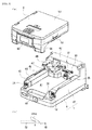
FIG. 3(a) is a perspective view showing a condition with the drug cassette removed from the support base ofFIG. 2 , andFIG. 3(b) is a schematic view showing a position for detecting drugs by a discharge sensor. -
FIG. 4 is an exploded perspective view of the support base ofFIG. 3 . -
FIG. 5 is a perspective view showing the base main body of the support base ofFIG. 4 as viewed from a different direction. -
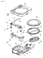
FIG. 6 is an exploded perspective view of the drug cassette ofFIG. 2 . -
FIG. 7 is a perspective view showing the cassette bottom part of the drug cassette ofFIG. 6 . -
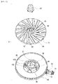
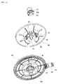
FIG. 8 is a perspective view showing the first rotating body, second rotating body and height regulator ofFIG. 6 . -
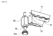
FIG. 9 is a perspective view showing the height regulator ofFIG. 8 as viewed from a different angle. -
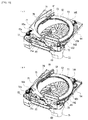
FIG. 10(a) is a perspective view of a state with the lid body and cassette torso removed from the drug cassette shown inFIG. 3 and the width regulator moved to a narrow width position, andFIG. 10(b) is a perspective view with the width regulator moved to a wide width position. -
FIG. 11 is an exploded perspective view showing the first rotating body ofFIG. 10 as viewed from above. -
FIG. 12 is an exploded perspective view showingFIG. 11 as viewed from below. -
FIG. 13 is a flowchart showing dividing and packaging processing according to the present embodiment. - An embodiment according to the present invention is described below in accordance with the attached drawings. Note that in the description below, terminology which expresses a specific direction or position (terminology including "up", "down", "side", and "end") is used as necessary, but those terms are used in order to facilitate understanding of the invention with reference to the drawings, and the technical scope of the present invention is not limited by the meaning of those terms. Furthermore, the following description is essentially merely an illustrative example, and is not intended to limit the present invention, its applicable objects, or its applications.
-
FIG. 1 is a schematic view of a drug packaging device according to the present embodiment. The drug packaging device thereof is provided, in order from the top side, with a plurality offirst drug feeders 2, a plurality ofsecond drug feeders 3, a hand distributeddrug supply unit 4, and apackaging unit 5 respectively in a packaging devicemain body 1, and these components are driven and controlled by acontrol device 6. - The
first drug feeder 2 is a conventionally known feeder, and a plurality of thefirst drug feeders 2 is arranged vertically and to the right and left. Eachfirst drug feeder 2 houses multiple drugs by type (hereinafter, if the description of drugs is provided, the drugs are primarily tablets, but shall also include capsules). A prescribed number of drugs is discharged from the relevantfirst drug feeder 2 based on prescription data and the like. - The
second drug feeder 3 houses drugs with a low usage frequency, drugs for which the quantity must be counted, and the like. The details will be described later. - The hand distributed
drug supply unit 4 is used when tablets which are cut in half or drugs with a low usage frequency are distributed by hand and set in each area formed in a lattice shape and packaged by thepackaging unit 5. - The
packaging unit 5 unwinds and supplies packaging paper that has been wound into a roll, and packages, in single package portions, drugs that have been supplied from each drug feeder or the hand distributeddrug supply unit 4. - Next, the
second drug feeder 3, which is a characteristic part of the present invention, is described in detail. - The
second drug feeders 3 are arranged in parallel at the front surface of the packaging devicemain body 1 in a manner with a top row and a bottom row, each having four feeders in the right and left direction. As shown inFIG. 2 andFIG. 3 , eachsecond drug feeder 3 is configured from asupport base 7, and adrug cassette 8 that can be attached to and detached from thesupport base 7. - As shown in
FIG. 4 , thesupport base 7 is provided with a basemain body 9, constituent parts such as a plurality of motors mounted to the basemain body 9, and abase cover 10. - As shown in
FIG. 4 andFIG. 5 , the basemain body 9 is a flat board shape made from a synthetic resin material, and anRFID reader 11 is attached at the front side and center part. TheRFID reader 11 reads the RFID (Radio Frequency Identification) provided at the side of the drug cassette, and obtains information on thedrug cassette 8 thereof and the type of drugs contained therein, and the like. Furthermore, afirst motor 12, asecond motor 13, and acassette lock part 14 are attached at both sides of the basemain body 9. - The
first motor 12 is fixed to a first supportingpiece 15, which has a tip end part fixed to a corner part at one front end side of the basemain body 9. The first supportingpiece 15 is provided with a top surface part and a bottom surface part, which are opposing, and with a vertical surface part connecting the top and bottom surface parts. A rotating shaft of thefirst motor 12 pierces the vertical surface part, and afirst bevel gear 16 is fixed to the tip end part of the rotating shaft. Furthermore, a first rotatingshaft 17 is rotatably supported between the top and bottom surface parts of the first supportingpiece 15. Asecond bevel gear 18 which meshes with thefirst bevel gear 16 is fixed at the center portion of the first rotatingshaft 17, and at an upper portion, afirst spur gear 19, which meshes with aspur gear 70a (seeFIG. 6 ) of aheight regulator 69, which is provided at the later-describeddrug cassette 8 side, is secured. - Like the
first motor 12, thesecond motor 13 is fixed to a second supportingpiece 20, which has the same configuration as the first supportingpiece 15 and has a tip end part that is fixed to a corner part of the other front end side of the basemain body 9. Athird bevel gear 21 is fixed to the tip end of a rotating shaft of thesecond motor 13. A second rotatingshaft 22 is rotatably supported between the top and bottom surfaces of the second supportingpiece 20. Afourth bevel gear 23, which meshes with thethird bevel gear 21, is fixed at a center part of the secondrotating shaft 22, and at an upper portion thereof, asecond spur gear 24, which meshes with aspur gear 72b (seeFIG. 6 ) of awidth regulator 71, which is provided at the later-describeddrug cassette 8 side, is secured. - The
cassette lock part 14 is provided to lock thesecond drug cassette 8 mounted to thesupport base 7 such that it cannot fall out. Thecassette lock part 14 has anoperation piece 26, and asolenoid 27 for driving theoperation piece 26 attached to anattachment piece 25, which is fixed to thesupport base 7. Theoperation piece 26 has a shaft part that is rotatably supported between opposing surfaces of theattachment piece 25, and a protrudingpiece 28 is movably attached to one end side. The protrudingpiece 28 is biased upward by a spring (not illustrated) arranged between the protrudingpiece 28 and theattachment piece 25. Furthermore, the other end part of theoperation piece 26 is rotatably linked to a rod tip end of thesolenoid 27. Through this, when thesolenoid 27 is excited and driven, theoperation piece 26 rotates, and the protrudingpiece 28 moves up and down and appears and disappears from a top surface of abottom part 41, and engages and disengages with an interlocking concavity (not illustrated) formed at the bottom surface of the later-describeddrug cassette 8. - Furthermore, an
attachment plate 29 extending vertically upward is fixed to the rear side of the basemain body 9. Athird motor 30, afourth motor 31, and a chargingunit 32 are attached to theattachment plate 29. - The
third motor 30 has a tip end side that is fixed to the lower side of theattachment plate 29, and afirst pulley 33 is fixed to the tip end part of a rotating shaft projecting therefrom. A rotating shaft having asecond pulley 34 fixed to one end and afirst driving gear 35 fixed to the other end is rotatably supported at the upper side of theattachment plate 29. Afirst belt 36 is extended between thefirst pulley 33 and thesecond pulley 34 such that the driving force of thethird motor 30 is transmitted to thefirst driving gear 35. Thefirst driving gear 35 meshes with a first drivengear 61 provided at the later-described drug cassette side, and is capable of rotating the firstrotating body 51 in the forward and reverse directions. - Like the
third motor 30, thefourth motor 31 has a tip end side that is fixed to the lower side of theattachment plate 29, and athird pulley 37 is fixed to a tip end part of the rotating shaft projecting therefrom. At the upper side of theattachment plate 29, a rotating shaft is rotatably supported with afourth pulley 38 fixed at one end, and asecond driving gear 39 fixed at the other end. Asecond belt 40 is extended between thethird pulley 37 and thefourth pulley 38 such that the driving force of thefourth motor 31 is transmitted to thesecond driving gear 39. Thesecond driving gear 39 meshes with a second-drivengear 64 provided at the later-described drug cassette side such that the secondrotating body 52 can be rotated in the forward and reverse directions. - The charging
unit 32 is configured of terminals and the like that enable power to be supplied to thedrug cassette 8 side by mounting thedrug cassette 8 to the support base 7 (for example, the chargingunit 32 may be configured such that one of either the chargingunit 32 on thedrug cassette 8 side or on thesupport base 7 side is a male type terminal, and the remaining other is a female type terminal). Through this, when thedrug cassette 8 is mounted to thesupport base 7, charging can be performed by supplying power to a battery (or capacitor) of the later-describeddrug cassette 8 side via the chargingunit 32. - As shown in
FIG. 4 , thebase cover 10 is configured by thebottom part 41 and aback surface part 42. Aguide unit 43 extending to the front and back at both sides is formed at thebottom part 41. Acassette bottom part 54 of the later-describeddrug cassette 8 is guided by the inside surfaces of theguide unit 43. Anauxiliary wall 44 is formed projecting further upward from the outside edge of the top surface of theguide unit 43. Aguide receiving piece 45 projects to the inside from theauxiliary wall 44 such that aguide piece 58 formed at thecassette bottom part 54 of thedrug cassette 8 is guided. As shown inFIG. 3(a) , part of thefirst spur gear 19 is exposed from the front end surface of the rightside guide unit 43, and part of thesecond spur gear 24 is exposed from the front end surface of the leftside guide unit 43. Furthermore, adepression part 46 is formed at the front end center of thebottom part 41 in order to simplify gripping of the front end part of thedrug cassette 8. In addition, a slit-shaped opening is formed in the top surface of thebottom part 41 at a portion near thedepression part 46, and the protrudingpiece 28 of thecassette lock part 14 can appear through and disappear from that opening. - Tip end parts (gear portions) of the
first driving gear 35 and thesecond driving gear 39 are exposed from theback surface part 42. Moreover, ahopper 47 for guiding drugs dispensed from thedrug cassette 8 is attached to theback surface part 42. Of course, thehopper 47 may also be fixed to thedrug cassette 8. Furthermore, drugs discharged to thehopper 47 are detected by adischarge sensor 48 and counted. - An optical sensor is used for the
discharge sensor 48, and as shown inFIG. 3(b) , a light path is established further to the downward side by a prescribed dimension (for example, 1 mm) than the top surface of the secondrotating body 52. In other words, by moving the center of gravity position of the drug from the top surface of the secondrotating body 52 to a position at which the drug will drop, a position at which the drug is tilted can be detected. Through this, if the drug quantity is to be counted, rotation of the secondrotating body 52 can be stopped at the point in time when the final drug is reliably discharged, and therefore discharge of the next drug can be reliably prevented. - As shown in
FIG. 6 , thedrug cassette 8 houses acylindrical body 50 in a cassettemain body 49, the firstrotating body 51 is arranged at a lower end opening part of thiscylindrical body 50, the secondrotating body 52 is arranged at the outer periphery of the upper end opening part of thecylindrical body 50, and the upper opening part of the cassettemain body 49 is closed by the lid body 53 (seeFIG. 3 ). - The cassette
main body 49 is provided with acassette bottom part 54, a cassettefront end part 55, and acassette torso 56. - Both side parts of the
cassette bottom part 54 extend upward, and configure aside surface part 57 that is guided by theguide unit 43 of thesupport base 7. Furthermore, at the upper edge of theside surface part 57, the part extends further in the side direction, and theguide piece 58 is formed as the side edge part thereof. Theguide piece 58 regulates movement in the upward direction using aguide receiving piece 45 formed at thebase cover 10 of thesupport base 7. To the right of the center part of the bottom surface of thecassette bottom part 54, acylindrical bearing part 59 projected at a slant is formed, and arotating shaft 51a is rotatably supported at the bearingpart 59. - As shown in
FIG. 7 , the front end portion of thecassette bottom part 54 extends upward such that adisplay panel 60 can be attached. Here, an electronic paper is used for thedisplay panel 60. Electronic paper is media that requires power to rewrite the display details, but does not consume power in the display state. Furthermore, various display data such as the name and quantity of the drugs to be housed inside thedrug cassette 8 based on the prescription data, and in some cases, the name of the patient, is input and displayed on the electronic paper. Through this, the user can know at one glance what drugs are contained in thedrug cassette 8. Moreover, by displaying the name and quantity of the drugs in a rewritable manner, changes in drugs and the like can be flexibly accommodated. Furthermore, even when the drugs are to be replenished, the replenishment work can be implemented after confirming the details displayed on the electronic paper. - However, with electronic paper, even if display data is input, it takes some time for the display to be rewritten. Therefore, when a charging type battery (or capacitor) which is not illustrated is provided, and the
drug cassette 8 is mounted to thesupport base 7, this battery (or capacitor) is charged. In this manner, even if thedrug cassette 8 is removed from thesupport base 7 immediately after a signal is input to the electronic paper, power is supplied to the electronic paper from the battery (or capacitor), and the display details can be rewritten. Note that thedrug cassette 8 can be removed from thesupport base 7 by operating thecassette lock part 14 and cancelling the locked state with a prescribed amount of time required from the startup to completion of display data input. The time until the lock is cancelled in this case may be stored in memory by a memory means (not illustrated) on the devicemain body 1 side in advance. - In this manner, according to the
drug cassette 8 of the above-described configuration, even if electronic paper is being used, if display data is input, thedrug cassette 8 can be immediately removed from thesupport base 7, and work to replenish the drugs or the like can be performed. When thedrug cassette 8 is removed from thesupport base 7, the electronic paper consumes zero electric power, and therefore even with a battery (or capacitor), the desired display data can be displayed without any problem. Moreover, the user can advance with work to replenish the relevant drugs in accordance with the displayed details. - As shown in
FIG. 6 , the firstrotating shaft 63, which has one end fixed to the first drivengear 61 and the other end fixed to athird driving gear 62, and the secondrotating shaft 66, which has one end fixed to the second drivengear 64 and the other end fixed to a fourth driving gear 65 (hypoid gear), are respectively supported in a rotatable manner at the back surface side of thecassette bottom part 54. Note that the top surface of thecassette bottom part 54 is covered by a cover body (not illustrated) having a roughly C-shape. - The cassette
front end part 55 has a firsthousing recess part 67 linked with a secondhousing recess part 68 configuring the corners at both sides of the front end of thedrug cassette 8, and is fixed to thecassette bottom part 54. Ascrew shaft 70 for driving theheight regulator 69 is rotatably supported at the firsthousing recess part 67. Afirst shaft member 72 for driving thewidth regulator 71 is arranged at the secondhousing recess part 68. - As shown in
FIG. 8 andFIG. 9 , theheight regulator 69 is provided with acylinder part 73, and aheight regulation unit 74 extending from thiscylinder part 73. A female screw that is screwed together with a male screw formed at the outer circumferential surface of thescrew shaft 70 is formed at thecylinder part 73, and is positioned inside the firsthousing recess part 67 of the cassettefront end part 55. Theheight regulation unit 74 has afirst guide surface 75 arranged at a desired spacing with respect to the top surface of the secondrotating body 52, and asecond guide surface 76 that configures a part of the outer peripheral surface of the drug conveying path in the circumferential direction through the secondrotating body 52. Thespur gear 70a is integrated at the lower end part of thescrew shaft 70, and meshes with thefirst spur gear 19 of thesupport base 7 side. Through this, the drive power from thefirst motor 12 is transmitted to thescrew shaft 70, the position at which the male screw and the female screw of thecylinder part 73 are screwed together changes, and theheight regulator 69 moves up and down. Moreover, the position of thefirst guide surface 75 is adjusted with respect to the top surface of the secondrotating body 52. As a result, the height of drugs conveyed in the circumferential direction by the secondrotating body 52 is regulated by theheight regulator 69. Furthermore, anauxiliary piece 77 is attached at the top surface of theheight regulation unit 74 in a manner that allows rotation centered on a support shaft. Theauxiliary piece 77 is biased by a spring (not illustrated) provided at the support shaft such that it stands upright from the top surface of theheight regulation unit 74. In this manner, if theheight regulator 69 is lowered, theauxiliary piece 77 is made to stand upright by the biasing force of the spring, the gap that is generated between the top surface of theheight regulation unit 74 and the bottom surface of thelid body 53 is covered, and the movement inward of drugs can be prevented. - As shown in
FIG. 10 , thewidth regulator 71 has afirst guide surface 78 gradually curved to the outer diameter side along the outer circumference of the secondrotating body 52, and a flatsecond guide surface 79 that is a continuation of thefirst guide surface 78. Thesecond shaft member 80 is arranged at the outer diameter side of thefirst guide surface 78, and has a drivengear 80a, which meshes with thedriving gear 72a provided at the upper end part of thefirst shaft member 72, provided at one end part thereof. At the other end side of thesecond shaft member 80, a male screw, which screws into the female screw of afemale screw member 71a integrated with thewidth regulator 71, is formed. Moreover, when thefirst shaft member 72 rotates in the forward and reverse directions, thesecond shaft member 80 rotates via thedriving gear 72a and the drivengear 80a, and thewidth regulator 71 moves back and forth via thefemale screw member 71a between the wide width position shown inFIG. 10(a) and the narrow width position shown inFIG. 10(b) . Note that the top surface of thewidth regulator 71 is covered by a protective cover (not illustrated) along with thedriving gear 72a and the drivengear 80a. - As shown in
FIG. 6 , thecassette torso 56 is in a rectangular frame body shape, and the front end side has respective housing parts formed with each of thehousing recess parts front end part 55. Furthermore, at the inner circumferential side of thecassette torso 56, aninner wall 56a, which configures a part (approximately half) of the inner circumferential surface along the outer circumferential edge of the secondrotating body 52, is formed. A discharge guide piece 81 (seeFIG. 10 ) is attached to one end part of theinner wall 56a to guide drugs conveyed by the secondrotating body 52 to thehopper 47. - The
cylindrical body 50 has an upper end opening part along the inner circumferential edge of the secondrotating body 52, and extends to the downward side. The lower end opening part of thecylindrical body 50 is cut at an incline tailored to the inclination angle of the firstrotating body 51. A drug housing part 82 (seeFIG. 8 ) capable of housing drugs is formed by the inner circumferential surface of thecylindrical body 50 and the top surface of the firstrotating body 51. - As shown by
FIG. 11 andFIG. 12 , the firstrotating body 51 is disk shaped, and is configured of atop surface part 83 and abottom surface part 84. Furthermore, the firstrotating body 51 is arranged at the lower end opening part of thecylindrical body 50, and is tilted with respect to the horizontal surface. - An
upper cylinder part 85 is formed at the center of the top surface of thetop surface part 83, and throughholes 86 are formed at four places around theupper cylinder part 85. Theupper cylinder part 85 is covered by acap 87.Leg parts 88 are formed at thecap 87 at four places equally spaced from the lower opening part. Theleg parts 88 are inserted into each of the throughholes 86, and aclaw part 88a formed at the tip end of each of theleg parts 88 is locked by locking claws of a later-describedlocking piece 100. A plurality ofridges 89 are formed around the throughholes 86 and extend from a portion adjacent to the throughholes 86 toward the outer diameter side. Each of theridges 89 is inclined to the side opposite the rotational direction of the firstrotating body 51 with respect to a straight line extending from the rotational center of the firstrotating body 51 in the radial direction. Moreover, each of theridges 89 has a firstinclined surface 90 projecting from the top surface of thetop surface part 83, and a secondinclined surface 91 inclined in the rotational direction so as to gradually approach the top surface of thetop surface part 83. The inclination angle of the firstinclined surface 90 with respect to the top surface of thetop surface part 83 is set so as to be sufficiently larger than the inclination angle of the secondinclined surface 91. The firstinclined surface 90 may also be configured with a surface that is perpendicular with respect to the top surface of thetop surface part 83. Through this, when the firstrotating body 51 rotates, drugs are pressed by the secondinclined surface 91 and moved in the rotational direction. Because the drugs are pressed by the secondinclined surface 91, the component of force in the rotational direction is not very large, and an appropriate amount is smoothly conveyed in the rotational direction. Furthermore, because theridges 89 extend at an incline toward the side opposite the rotational direction, the drugs are moved to the outer diameter side as well, and are transferred to the top surface of the secondrotating body 52. -
Leg parts 92 arranged at four places equidistantly in the circumferential direction, andfirst projection parts 93 andsecond projection parts 94 arranged to the inside of theleg parts 92 are formed at the bottom surface of thetop surface part 83. Theleg part 92 is reinforced by both end parts extending to the outer diameter side. Thefirst projection parts 93 are arranged at two places at symmetrical positions centered on the rotational center of the firstrotating body 51. Thesecond projection parts 94 have a projection dimension that is larger than that of thefirst projection parts 93, and are arranged between thefirst projection parts 93. - A
lower cylinder part 95 for which the top surface is closed is formed at a center of thebottom surface part 84, and therotating shaft 51a, which is rotatably supported at the bearingpart 59 of thecassette bottom part 54 from the lower opening part, is linked and integrated. - A circular shaped
recess part 96 is formed at a center part of the top surface of thebottom surface part 84, and theleg parts 92 of thetop surface part 83 are arranged at the outer circumferential side thereof. Moreover, thelower cylinder part 95 projects at the center part of the bottom surface of therecess part 96, and asupport shaft 97 is formed at the center part of the top surface thereof. Thesupport shaft part 97 is disposed at theupper cylinder part 85 of thetop surface part 83, and rotatably supports thetop surface part 83. Moreover, mountain-shapedparts 98 andsupport recess parts 99 are alternatingly formed in the circumferential direction at the outer circumferential surface of theshaft part 97. Thefirst projection parts 93 abut and are arranged at the inclined portion of adjacent mountain-shaped parts 98 (upper side of the support recess part 99), and thesecond projection parts 94 are arranged at the support recess parts of the remaining two places. Through this, thetop surface part 83 and thebottom surface part 84 rotate in an integrated manner. Of course, if an unreasonable load is acted on thetop surface part 83 and rotation is hindered, thesecond projection parts 94 come off from thesupport recess part 99, thetop surface part 83 rotates with respect to thebottom surface part 84, and damage to the firstrotating body 51 is prevented. Moreover, lockingpieces 100 project at four places in an equidistant manner around theshaft part 97. A lockingclaw 100a is formed at the tip end of thelocking piece 100 at the inside, and locks theclaw part 88a formed on theleg part 88 of thecap 87. - A first driven
gear 101 is formed at the outer peripheral edge of the bottom surface of thebottom surface part 84. Thethird driving gear 62 of the firstrotating shaft 63 meshes with the first drivengear 101, and drive power of thethird motor 30 is transmitted from this firstrotating shaft 63 via thefirst driving gear 35 of thesupport base 7 side. - As shown in
FIG. 6 andFIG. 10 , the secondrotating body 52 has a ring shaped body, which is arranged at the outer circumferential side of the upper opening part of thecylindrical body 50 and has a prescribed width in the radial direction. A ring shapedprojection 102 projecting upward is formed at the inner circumferential edge of the secondrotating body 52. The height of the ring shapedprojection 102 is such that movement of drugs from the firstrotating body 51 can be performed smoothly, and such that dropping to the inside by conveyance of the drugs through rotation of the secondrotating body 52 can be suppressed. Furthermore, a second drivengear 103 is formed in the circumferential direction at the bottom surface of the secondrotating body 52. Thefourth driving gear 65 meshes with the second drivengear 103 such that drive power from thefourth motor 31 can be transmitted. - A
step part 104 is formed at the outer circumferential edge of the secondrotating body 52. Thestep part 104 is such that upward floating due to thepresser piece 105 attached to thecassette torso 56 arranged above the secondrotating body 52 can be prevented. Thestep part 104 is positioned at the outer diameter side of the position where theinner wall 56a of thecassette torso 56 is arranged. Therefore, drugs conveyed along the top surface of the secondrotating body 52 are moved to thestep part 104 and do not become caught between thepresser piece 105, and the top surface of the secondrotating body 52 is also not damaged. Furthermore, thepresser piece 105 is arranged above thefourth driving gear 65. Through this, upward movement of the portion on which the most force acts can be reliably suppressed. Moreover, play, positional deviation, and the like after the unit has been disassembled, cleaned, and then reassembled can be prevented. - Note that the second
rotating body 52 may also be set such that it rotates at a higher speed than the firstrotating body 51. Through this, the spacing between drugs moved from the firstrotating body 51 to the secondrotating body 52 can be widened, and erroneous detection of the number of drugs that have been discharged can be prevented. - The
lid body 53 is attached such that it is capable of rotating centered at one side part of thecassette torso 56. An auxiliary panel that covers the top surface of thewidth regulator 71 is rotatably attached to the rotating center of thelid body 53. - According to the
drug cassette 8 of the above-described configuration, a compact configuration can be achieved by effectively utilizing the dead space of the four corners formed in the cassettemain body 49. More specifically, the firstrotating shaft 17 for driving theheight regulator 69 and thefirst motor 12 for rotating this firstrotating shaft 17 are arranged at one of the corners at the front surface side. In addition, the secondrotating shaft 22 for driving thewidth regulator 71 and thesecond motor 13 for rotating this secondrotating shaft 22 are arranged at the other corner. Furthermore, thethird motor 30 for rotating the firstrotating body 51, thefourth motor 31 for rotating the secondrotating body 52, and the like are arranged at one corner at the back surface side, and thehopper 47 for drug discharge is arranged at the other corner at the back surface side. - Moreover, the
drug cassette 8 of the above-described configuration can be disassembled and cleaned (washed for example). More specifically, thedrug cassette 8 is configured such that thecassette torso 56 can be removed from thecassette bottom part 54, and theheight regulator 69, thewidth regulator 71, the firstrotating body 51, and the secondrotating body 52 can be removed. Theheight regulator 69 can be removed together with the firstrotating shaft 17 from the cassettefront end part 55. Thewidth regulator 71 can be removed together with thesecond shaft member 80 from the cassettefront end part 55. The firstrotating body 51 and the secondrotating body 52 can be easily removed by merely removing the cover body from thecassette bottom part 54. Moreover, the firstrotating body 51 can be disassembled into thetop surface part 83 and thebottom surface part 84 by removing thecap 87. - In this manner, the parts of the
drug cassette 8 that contact drugs can be disassembled and cleaned, and therefore if the type of drug is changed, or the like, contamination (mixing of different types of drugs) can be reliably prevented even if some of the drugs are damaged or dropped and powder is generated. - The
control device 6 drives and controls each motor, thepackaging unit 5, and the like based on prescription data received from a server (not illustrated) or the like and on detection signals from thedischarge sensor 48. - Next, the operation of the drug packaging device having the above-described configuration is described. Here, the operation of dispensing drugs from the
second drug feeder 3, which is a characteristic portion of the present invention, is described in detail, and a description of other operations is omitted. - If a drug is one with a low usage frequency, or the quantity of the drugs must be counted, the drugs are housed in the
second drug feeder 3, and are dispensed and packaged (subjected to dividing and packaging processing) as follows. - More specifically, as shown in
FIG. 13 , if prescription data is received (step S1), thesecond drug feeder 3 containing the drugs included in the prescription data thereof is identified (step S2). Namely, memory details from a data table of a memory means (not illustrated) are rewritten at any time based on whether eachsecond drug feeder 3 is in a usage state or in an unused state. Furthermore, based on the drugs contained in the prescription data, the data table is referenced, and of thesecond drug feeders 3 in which the relevant drugs are housed, thesecond drug feeder 3 that is not being used at that time is identified. Note that the memory details in the data table for the identifiedsecond drug feeder 3 are rewritten at that time to indicate that the identifiedsecond drug feeder 3 is in a usage state. - Based on the drug information (shape, size, etc.), the
height regulator 69 and thewidth regulator 71 are operated (steps S3 and S4). More specifically, theheight regulator 69 is raised or lowered via the firstrotating shaft 17 by driving thefirst motor 12, and a gap (height) that enables passage of only one drug is formed as the gap between the bottom surface of theheight regulator 69 and the top surface of the secondrotating body 52. The secondrotating shaft 22 is rotated by driving thesecond motor 13, thewidth regulator 71 is moved horizontally via thesecond shaft member 80, and the position of thefirst guide surface 78 of thewidth regulator 71 is adjusted. Through this, the gap in the radial direction from the inner circumferential edge of the secondrotating body 52 to thefirst guide surface 78 is adjusted to a dimension that allows movement of only a single drug. - Furthermore, the
fourth motor 31 is driven to begin forward rotation of the second rotating body 52 (step S5), and thethird motor 30 is driven to begin forward rotation of the first rotating body 51 (step S6). Through the rotation of the firstrotating body 51, the drugs contained in thedrug cassette 8 are subjected to frictional resistance from the secondinclined surface 91 of theridges 89 formed at the top surface of the firstrotating body 51, and are moved in the rotational direction. Furthermore, as described above, theridges 89 are formed from the inner diameter side to the outer diameter side in a manner which inclines to the opposite direction of the direction of rotation with respect to a straight line towards the radial direction from the rotating center of the first rotating body, and therefore the drugs easily move to the outer perimeter side as well. Through this, drugs on the firstrotating body 51 move over the ring shapedprojection 102 of the secondrotating body 52, and move to the top surface of the secondrotating body 52. Drugs that have moved to the top surface of the secondrotating body 52 are conveyed in the rotational direction in association with the rotation of the secondrotating body 52, and because of theheight regulator 69 and thewidth regulator 71, only one drug is moved to thehopper 47 at the discharge side. - Drugs that have been moved to the
hopper 47 are discharged one at a time to thehopper 47 and are guided to thepackaging unit 5. Drugs discharged to thehopper 47 are detected by thedischarge sensor 48. If a drug is detected by thedischarge sensor 48 within a prescribed amount of time from the startup of rotation of the firstrotating body 51 and the second rotating body 52 (step S7: YES), then the rotation of the secondrotating body 52 is stopped (step S8). Incidentally, as described previously, drugs that can be detected by thedischarge sensor 48 are drugs that are in a state of beginning to reliably drop from the secondrotating body 52 such as a tilted drug. Accordingly, by stopping the rotation of the secondrotating body 52 in this state, drugs can be reliably discharged only one at a time. - Furthermore, if the prescribed number of packages as noted by the prescription data has not been reached (step S10: NO), a decision is made as to whether the input of the detection signal from the
discharge sensor 48 has disappeared or not (step S11). If the input of the detection signal from thedischarge sensor 48 has disappeared (step S11: YES), rotation of the secondrotating body 52 is resumed (step S12). Through this, rotation of the secondrotating body 52 can be resumed after confirming that only a single drug was discharged based on the detection signal of thedischarge sensor 48. In other words, drugs can be reliably discharged one at a time. During this time, thepackaging unit 5 is driven and controlled, and sequentially discharged drugs are packaged in single package portions. - Incidentally, if a drug is spherical, even if the first
rotating body 51 is rotating, in some cases the drug will rotate on the secondinclined surface 91 of theridges 89 and will be unable to move to the second rotating body side. Moreover, a similar thing can occur when the drug is cylindrically shaped or elliptical. In this type of case, the drugs cannot be detected by thedischarge sensor 48 even though the firstrotating body 51 and the secondrotating body 52 are rotating. - Therefore, if a drug cannot be detected by the
discharge sensor 48 within a prescribed amount of time even though the firstrotating body 51 and the secondrotating body 52 are rotating (step S7: NO), the firstrotating body 51 is temporarily rotated in reverse (step S9). Through this, a drug that was rotated there is pressed by the firstinclined surface 90, which is more inclined than the secondinclined surface 91. As a result, even if a drug is spherical for example, it can be moved smoothly to the secondrotating body 52 side. - Next, if the prescribed number of packages as noted by the prescription have been packaged (step S10: YES), packaging processing by the
second drug feeder 3 is ended. - Note that even if a drug is missing, similar to the previous description, the drug cannot be detected by the
discharge sensor 48, but the matter of rotating the firstrotating body 51 in reverse may be performed also for a case when a drug cannot be moved to the secondrotating body 52 even if the shape of the drugs is spherical or the like, or a drug is not missing. - The present invention is not limited to the configuration described for the present embodiment, and various modifications may be made.
- For example, with the above-described embodiment, a case was described that uses a
second drug feeder 3 and packages drugs with a low usage frequency. However, thesecond drug feeder 3 thereof can also be used for a case in which the quantity of a drug is counted. In this case, a route which guides drugs discharged from thehopper 47 to the front side of the mounteddrug cassette 8 and is separate from the discharge route to the packaging unit side, which is similar to the one described above, is formed, and drugs discharged from there may be collected in a vial bottle or the like. Moreover, this method can also be used when dispensing a prescribed quantity of drugs into a vial bottle. - Furthermore, with the above-described embodiment, a change to details displayed on the
display panel 60 was performed based on the display data input from the packaging device main body side with thedrug cassette 8 mounted to thesupport base 7, but the change may also be performed with the drug cassette removed from thesupport base 7. In other words, if thedrug cassette 8 is equipped with a receiver such that it can wirelessly receive a control signal from the packaging device main body side, display information can be sent to thedrug cassette 8 with thedrug cassette 8 removed from thesupport base 7, and the display information can be reflected on the electronic paper using power from the rechargeable battery. -
- 1
- packaging device main body
- 2
- first drug feeder
- 3
- second drug feeder
- 4
- hand distributed drug supply unit
- 5
- packaging unit
- 6
- control device
- 7
- support base
- 8
- drug cassette
- 9
- base main body
- 10
- base cover
- 11
- RFID reader
- 12
- first motor
- 13
- second motor
- 14
- cassette lock part
- 15
- first supporting piece
- 16
- first bevel gear
- 17
- first rotating shaft
- 18
- second bevel gear
- 19
- first spur gear
- 20
- second supporting piece
- 21
- third bevel gear
- 22
- second rotating shaft
- 23
- fourth bevel gear
- 24
- third spur gear
- 25
- attachment piece
- 26
- operation piece
- 27
- solenoid
- 28
- protruding piece
- 29
- attachment plate
- 30
- third motor (drive means)
- 31
- fourth motor (drive means)
- 32
- charging unit
- 33
- first pulley
- 34
- second pulley
- 35
- first driving gear
- 36
- first belt
- 37
- third pulley
- 38
- fourth pulley
- 39
- second driving gear
- 40
- second belt
- 41
- bottom part
- 42
- back surface part
- 43
- guide unit
- 44
- auxiliary wall
- 45
- guide receiving piece
- 46
- depression part
- 47
- hopper
- 48
- discharge sensor
- 49
- cassette main body
- 50
- cylindrical body
- 51
- first rotating body
- 52
- second rotating body
- 53
- lid body
- 54
- cassette bottom part
- 55
- cassette front end part
- 56
- cassette torso
- 57
- side surface part
- 58
- guide piece
- 59
- bearing part
- 60
- display panel
- 61
- first driven gear
- 62
- third driving gear
- 63
- first rotating shaft
- 64
- second driven gear
- 65
- fourth driving gear
- 66
- second rotating shaft
- 67
- first housing recess part
- 68
- second housing recess part
- 69
- height regulator
- 70
- screw shaft
- 71
- width regulator
- 72
- first shaft member
- 73
- cylinder part
- 74
- height regulation unit
- 75
- first guide surface
- 76
- second guide surface
- 77
- auxiliary piece
- 78
- first guide surface
- 79
- second guide surface
- 80
- second shaft member
- 81
- discharge guide piece
- 82
- drugs housing part
- 83
- top surface part
- 84
- bottom surface part
- 85
- upper cylinder part
- 86
- through hole
- 87
- cap
- 88
- leg part
- 89
- ridges
- 90
- first inclined surface
- 91
- second inclined surface
- 92
- veg part
- 93
- first proj ection parts
- 94
- second proj ection parts
- 95
- lower cylinder part
- 96
- recess part
- 97
- support shaft part
- 98
- mountain-shaped part
- 99
- support recess part
- 100
- locking piece
- 101
- first driven gear
- 102
- ring shaped projection
- 103
- second driven gear
- 104
- step part
- 105
- presser piece
Claims (9)
- A drug cassette comprising:a cylindrical body arranged in a cassette main body for accommodating drugs,a first rotating body arranged on a bottom surface side of the cylindrical body in the cassette main body, and capable of rotating around a first rotating shaft; anda second rotating body arranged on an outer periphery of an opening part of the cylindrical body in the cassette main body, and capable of rotating around a second rotating shaft; whereina drive means which rotates and drives at least the first rotating body and the second rotating body is arranged in a surplus space in the cassette main body.
- The drug cassette according to claim 1, further comprising:a height regulator for regulating the height of drugs to be conveyed by the second rotating body; whereina drive mechanism for moving the height regulator is arranged in surplus space of the cassette main body.
- The drug cassette according to claim 1 or claim 2, further comprising:a width regulator for regulating the width of drugs to be conveyed by the second rotating body; whereina drive mechanism for moving the width regulator is arranged in surplus space of the cassette main body.
- The drug cassette according to any one of claims 1 to 3, further comprising:a hopper for discharging drugs to be conveyed by the second rotating body; whereinthe hopper is arranged in surplus space of the cassette main body.
- The drug cassette according to any one of claims 1 to 4, wherein the first rotating body comprises a plurality of ridges extending on a top surface from a rotating center side to an outer diameter side, and the ridges have an inclination angle of a second inclined surface of a rotational direction side that is smaller compared to an inclination angle of a first inclined surface of a reverse side of the rotation direction.
- The drug cassette according to any one of claim 1 to 5, further comprising:a drug detection means for detecting drugs discharged to the outside by rotation of the second rotating body; anda control means for temporarily rotating the first rotating body in reverse when drugs are not detected by the drug detection means even though the first rotating body and the second rotating body are being rotated.
- The drug cassette according to any one of claims 1 to 5, further comprising a drug detection means arranged so as to be capable of detecting drugs tilted due to a center of gravity position being separated from the second rotating body.
- The drug cassette according to any one of claims 1 to 7, wherein a step part is formed on an outer peripheral edge of the second rotating body; and
a presser piece for pressing the step part is provided. - A drug packaging device comprising:the drug cassette according to any one of claims 1 to 8;a support base capable of attaching and detaching the drug cassette; anda packaging unit for packaging drugs dispensed from the drug cassette.
Applications Claiming Priority (2)
| Application Number | Priority Date | Filing Date | Title |
|---|---|---|---|
| JP2013193122 | 2013-09-18 | ||
| PCT/JP2014/074459 WO2015041220A1 (en) | 2013-09-18 | 2014-09-17 | Drug cassette and drug packaging device |
Publications (2)
| Publication Number | Publication Date |
|---|---|
| EP3047836A1 true EP3047836A1 (en) | 2016-07-27 |
| EP3047836A4 EP3047836A4 (en) | 2017-05-10 |
Family
ID=52688869
Family Applications (1)
| Application Number | Title | Priority Date | Filing Date |
|---|---|---|---|
| EP14845534.8A Withdrawn EP3047836A4 (en) | 2013-09-18 | 2014-09-17 | Drug cassette and drug packaging device |
Country Status (9)
| Country | Link |
|---|---|
| US (1) | US10099806B2 (en) |
| EP (1) | EP3047836A4 (en) |
| JP (1) | JP6477478B2 (en) |
| KR (1) | KR102142749B1 (en) |
| CN (1) | CN105491989A (en) |
| AU (1) | AU2014322134A1 (en) |
| CA (1) | CA2924984A1 (en) |
| TW (1) | TWI635857B (en) |
| WO (1) | WO2015041220A1 (en) |
Families Citing this family (11)
| Publication number | Priority date | Publication date | Assignee | Title |
|---|---|---|---|---|
| US10329040B2 (en) * | 2015-04-11 | 2019-06-25 | Yuyama Mfg. Co., Ltd. | Medicine dispensing cassette |
| AU2016362656B2 (en) | 2015-11-30 | 2021-03-25 | Yuyama Mfg. Co., Ltd. | Drug cassette, drug delivery device, and drug packaging device |
| CN109922775B (en) | 2016-11-15 | 2021-12-21 | 株式会社汤山制作所 | Medicament packaging device |
| JP6736064B2 (en) | 2017-01-04 | 2020-08-05 | 株式会社トーショー | Drug feeder |
| CN108275292B (en) * | 2018-03-13 | 2024-02-20 | 广东一方制药有限公司 | Integrated traditional Chinese medicine preparation machine |
| US20210166799A1 (en) * | 2018-08-28 | 2021-06-03 | Yuyama Mfg. Co., Ltd. | Medicine loading device and medicine recovery method |
| US20230329975A1 (en) * | 2020-10-26 | 2023-10-19 | Takazono Corporation | Drug supply device |
| EP4260839A4 (en) * | 2020-12-11 | 2024-10-30 | Tosho, Inc. | DRUG DELIVERY DEVICE |
| US12036185B2 (en) | 2021-07-19 | 2024-07-16 | Optum, Inc. | System and method to count pills |
| JP7817595B2 (en) * | 2021-09-03 | 2026-02-19 | 株式会社湯山製作所 | Medicine dispensing device |
| JP7703186B2 (en) * | 2022-03-25 | 2025-07-07 | 株式会社トーショー | Drug feeders and tablet packaging machines |
Family Cites Families (18)
| Publication number | Priority date | Publication date | Assignee | Title |
|---|---|---|---|---|
| JPS582113A (en) | 1981-06-25 | 1983-01-07 | F I T:Kk | Feeder |
| DE8216324U1 (en) | 1982-06-04 | 1982-09-23 | Endress U. Hauser Gmbh U. Co, 7867 Maulburg | PROBE FOR CAPACITIVE MEASUREMENT OF THE LEVEL IN A CONTAINER, ESPECIALLY OF HOT FUEL |
| JP2541997B2 (en) | 1987-08-12 | 1996-10-09 | ディーエスエム ナムローゼ フェンノートシャップ | Curing method with active energy rays |
| KR200247469Y1 (en) * | 1998-07-14 | 2002-02-19 | 김준호 | Refining cassette for automatic tablet dispenser |
| JP4346173B2 (en) * | 1999-10-06 | 2009-10-21 | 株式会社湯山製作所 | Tablet feeder |
| CN1280168C (en) * | 2000-02-16 | 2006-10-18 | 三洋电机株式会社 | Chemical feeding device |
| KR101379990B1 (en) * | 2007-10-23 | 2014-04-02 | 가부시키가이샤 유야마 세이사쿠쇼 | Drug delivery system, and drug delivery device |
| CN102327188B (en) * | 2008-09-18 | 2015-04-01 | 株式会社汤山制作所 | Tablet feeder |
| US9790017B2 (en) * | 2008-11-21 | 2017-10-17 | Yuyama Mfg. Co., Ltd. | Tablet feeder and pharmacy system |
| TWI485093B (en) * | 2008-11-21 | 2015-05-21 | Yuyama Mfg Co Ltd | Lozenge delivery device |
| CN102143734B (en) * | 2009-03-01 | 2014-01-08 | 株式会社汤山制作所 | Medicine box dispensing device |
| KR101800029B1 (en) * | 2009-04-17 | 2017-11-21 | 가부시키가이샤 유야마 세이사쿠쇼 | Drug feeder and drug delivery unit |
| WO2012099189A1 (en) * | 2011-01-20 | 2012-07-26 | 株式会社湯山製作所 | Medicine supply device and medicine calculation device using same |
| JP5196337B1 (en) * | 2011-04-28 | 2013-05-15 | 株式会社湯山製作所 | Drug inspection device and drug packaging device |
| KR101933238B1 (en) | 2011-07-22 | 2018-12-27 | 가부시키가이샤 유야마 세이사쿠쇼 | Packaged-medicine issuing device |
| EP2754627A4 (en) * | 2011-09-06 | 2015-08-05 | Yuyama Mfg Co Ltd | DRUG CASSETTE AND MEDICAMENT DELIVERY DEVICE |
| KR101968373B1 (en) * | 2012-02-10 | 2019-04-11 | 가부시키가이샤 유야마 세이사쿠쇼 | Medication cassette |
| EP3048051A4 (en) * | 2013-09-20 | 2017-05-03 | Takazono Technology Incorporated | Drug supply unit |
-
2014
- 2014-09-17 EP EP14845534.8A patent/EP3047836A4/en not_active Withdrawn
- 2014-09-17 WO PCT/JP2014/074459 patent/WO2015041220A1/en not_active Ceased
- 2014-09-17 AU AU2014322134A patent/AU2014322134A1/en not_active Abandoned
- 2014-09-17 KR KR1020167004354A patent/KR102142749B1/en active Active
- 2014-09-17 CN CN201480047176.0A patent/CN105491989A/en active Pending
- 2014-09-17 US US15/022,908 patent/US10099806B2/en active Active
- 2014-09-17 CA CA2924984A patent/CA2924984A1/en not_active Abandoned
- 2014-09-17 JP JP2015537929A patent/JP6477478B2/en active Active
- 2014-09-18 TW TW103132361A patent/TWI635857B/en active
Also Published As
| Publication number | Publication date |
|---|---|
| JP6477478B2 (en) | 2019-03-06 |
| EP3047836A4 (en) | 2017-05-10 |
| KR102142749B1 (en) | 2020-08-07 |
| CA2924984A1 (en) | 2015-03-26 |
| JPWO2015041220A1 (en) | 2017-03-02 |
| AU2014322134A1 (en) | 2016-04-07 |
| KR20160057386A (en) | 2016-05-23 |
| US20160229564A1 (en) | 2016-08-11 |
| CN105491989A (en) | 2016-04-13 |
| TW201545741A (en) | 2015-12-16 |
| TWI635857B (en) | 2018-09-21 |
| WO2015041220A1 (en) | 2015-03-26 |
| US10099806B2 (en) | 2018-10-16 |
Similar Documents
| Publication | Publication Date | Title |
|---|---|---|
| US10099806B2 (en) | Drug cassette and drug packaging device | |
| US7562791B2 (en) | Tablet filling device | |
| US7861492B2 (en) | Tablet filling device | |
| JP7471560B2 (en) | Medicine dispensing device | |
| US7721508B2 (en) | Tablet filling device | |
| US7770357B2 (en) | Tablet filling device | |
| CA2533265C (en) | Medicine supply apparatus and tablet case | |
| KR20140133540A (en) | Medication cassette | |
| CN109922775B (en) | Medicament packaging device | |
| JP2009023731A (en) | Tablet filling device | |
| US8468777B2 (en) | Tablet filling device | |
| JP4964199B2 (en) | Individual packaging medicine automatic supply equipment | |
| JP5822755B2 (en) | Dispensing audit support device | |
| JP4638793B2 (en) | Tablet supply device and tablet supply method | |
| JPH11114025A (en) | Powdered medicine supplying device | |
| JP2025089350A (en) | Drug feeder and drug dispensing device | |
| JP2019094171A (en) | Powder and granular material supply device | |
| JP2019094173A (en) | Powder and granular material supply device | |
| JP2022106557A (en) | Drug feeder and dispensing system | |
| JPH11114022A (en) | Powdered medicine supply device | |
| JP2019094172A (en) | Powder and granular material supply device |
Legal Events
| Date | Code | Title | Description |
|---|---|---|---|
| PUAI | Public reference made under article 153(3) epc to a published international application that has entered the european phase |
Free format text: ORIGINAL CODE: 0009012 |
|
| 17P | Request for examination filed |
Effective date: 20160318 |
|
| AK | Designated contracting states |
Kind code of ref document: A1 Designated state(s): AL AT BE BG CH CY CZ DE DK EE ES FI FR GB GR HR HU IE IS IT LI LT LU LV MC MK MT NL NO PL PT RO RS SE SI SK SM TR |
|
| AX | Request for extension of the european patent |
Extension state: BA ME |
|
| DAX | Request for extension of the european patent (deleted) | ||
| A4 | Supplementary search report drawn up and despatched |
Effective date: 20170411 |
|
| RIC1 | Information provided on ipc code assigned before grant |
Ipc: A61J 7/04 20060101ALI20170405BHEP Ipc: A61J 7/00 20060101ALI20170405BHEP Ipc: G07F 17/00 20060101ALI20170405BHEP Ipc: A61J 3/00 20060101AFI20170405BHEP Ipc: B65B 1/10 20060101ALI20170405BHEP Ipc: B65B 57/14 20060101ALI20170405BHEP |
|
| GRAP | Despatch of communication of intention to grant a patent |
Free format text: ORIGINAL CODE: EPIDOSNIGR1 |
|
| STAA | Information on the status of an ep patent application or granted ep patent |
Free format text: STATUS: GRANT OF PATENT IS INTENDED |
|
| INTG | Intention to grant announced |
Effective date: 20180425 |
|
| STAA | Information on the status of an ep patent application or granted ep patent |
Free format text: STATUS: THE APPLICATION IS DEEMED TO BE WITHDRAWN |
|
| 18D | Application deemed to be withdrawn |
Effective date: 20180906 |