EP3047786A1 - Endoscope - Google Patents
Endoscope Download PDFInfo
- Publication number
- EP3047786A1 EP3047786A1 EP14860905.0A EP14860905A EP3047786A1 EP 3047786 A1 EP3047786 A1 EP 3047786A1 EP 14860905 A EP14860905 A EP 14860905A EP 3047786 A1 EP3047786 A1 EP 3047786A1
- Authority
- EP
- European Patent Office
- Prior art keywords
- bending
- rotation
- amount
- force
- endoscope
- Prior art date
- Legal status (The legal status is an assumption and is not a legal conclusion. Google has not performed a legal analysis and makes no representation as to the accuracy of the status listed.)
- Withdrawn
Links
- 238000005452 bending Methods 0.000 claims abstract description 287
- 238000003780 insertion Methods 0.000 claims abstract description 25
- 230000037431 insertion Effects 0.000 claims abstract description 25
- 230000004044 response Effects 0.000 claims abstract description 7
- 230000006835 compression Effects 0.000 claims description 18
- 238000007906 compression Methods 0.000 claims description 18
- 238000006073 displacement reaction Methods 0.000 claims description 7
- 230000004048 modification Effects 0.000 description 55
- 238000012986 modification Methods 0.000 description 55
- 230000007935 neutral effect Effects 0.000 description 20
- 230000009471 action Effects 0.000 description 12
- 238000010586 diagram Methods 0.000 description 10
- 238000000926 separation method Methods 0.000 description 7
- 230000008859 change Effects 0.000 description 4
- 239000000470 constituent Substances 0.000 description 4
- 230000007423 decrease Effects 0.000 description 3
- 230000008901 benefit Effects 0.000 description 2
- 230000000694 effects Effects 0.000 description 2
- 229910001220 stainless steel Inorganic materials 0.000 description 2
- 239000010935 stainless steel Substances 0.000 description 2
- 230000007704 transition Effects 0.000 description 2
- 238000005299 abrasion Methods 0.000 description 1
- 238000004891 communication Methods 0.000 description 1
- 238000013461 design Methods 0.000 description 1
- 239000002184 metal Substances 0.000 description 1
- 238000000034 method Methods 0.000 description 1
- 230000003287 optical effect Effects 0.000 description 1
- 238000004904 shortening Methods 0.000 description 1
- 230000001131 transforming effect Effects 0.000 description 1
Images








Classifications
-
- A—HUMAN NECESSITIES
- A61—MEDICAL OR VETERINARY SCIENCE; HYGIENE
- A61B—DIAGNOSIS; SURGERY; IDENTIFICATION
- A61B1/00—Instruments for performing medical examinations of the interior of cavities or tubes of the body by visual or photographical inspection, e.g. endoscopes; Illuminating arrangements therefor
- A61B1/005—Flexible endoscopes
- A61B1/0051—Flexible endoscopes with controlled bending of insertion part
- A61B1/0057—Constructional details of force transmission elements, e.g. control wires
-
- A—HUMAN NECESSITIES
- A61—MEDICAL OR VETERINARY SCIENCE; HYGIENE
- A61B—DIAGNOSIS; SURGERY; IDENTIFICATION
- A61B1/00—Instruments for performing medical examinations of the interior of cavities or tubes of the body by visual or photographical inspection, e.g. endoscopes; Illuminating arrangements therefor
- A61B1/00002—Operational features of endoscopes
- A61B1/00039—Operational features of endoscopes provided with input arrangements for the user
- A61B1/00042—Operational features of endoscopes provided with input arrangements for the user for mechanical operation
-
- A—HUMAN NECESSITIES
- A61—MEDICAL OR VETERINARY SCIENCE; HYGIENE
- A61B—DIAGNOSIS; SURGERY; IDENTIFICATION
- A61B1/00—Instruments for performing medical examinations of the interior of cavities or tubes of the body by visual or photographical inspection, e.g. endoscopes; Illuminating arrangements therefor
- A61B1/005—Flexible endoscopes
- A61B1/0051—Flexible endoscopes with controlled bending of insertion part
- A61B1/0052—Constructional details of control elements, e.g. handles
-
- G—PHYSICS
- G02—OPTICS
- G02B—OPTICAL ELEMENTS, SYSTEMS OR APPARATUS
- G02B23/00—Telescopes, e.g. binoculars; Periscopes; Instruments for viewing the inside of hollow bodies; Viewfinders; Optical aiming or sighting devices
- G02B23/24—Instruments or systems for viewing the inside of hollow bodies, e.g. fibrescopes
- G02B23/2476—Non-optical details, e.g. housings, mountings, supports
Definitions
- the present invention relates to an endoscope which has a bending portion at a distal end side of an insertion portion and in which a bending operation of the bending portion is performed by a bending operation member provided on an operation portion on a hand side.
- an elongated insertion portion is flexible, and, generally, a bending portion which can be freely bending-operated in a predetermined direction according to a user's operation at hand is provided on a distal end side of the insertion portion.
- Conventional endoscopes are configured such that a bending operation of the bending portion is performed on a hand side by the operation member of a lever type, a joystick type or the like which is provided on the operation portion, for example, as disclosed in Japanese Patent Application Laid-Open Publication No. S62-38411 or Japanese Patent Application Laid-Open Publication No. 2009-89955 .
- the conventional endoscopes have a problem that, at time of performing a bending operation of the bending portion, a user is caused to be tired, and it is difficult to perform a slight bending operation.
- an object of the present invention is to provide an endoscope which reduces an amount of operation force of the operation member for performing a bending operation of the bending portion to prevent a user from being tired and make it possible to perform a slight bending operation.
- An endoscope of an aspect in the present invention includes: an insertion portion provided with a bending portion at a distal end part; an operation portion coupled to the insertion portion; operation wires insertedly arranged inside the insertion portion and the operation portion, the operation wires causing the bending portion to bend by being pulled/slackened; an operation member provided on the operation portion, the operation member performing a bending operation of the bending portion; a rotation member provided in the operation portion, the rotation member pulling/slackening the operation wires by rotating in conjunction with an operation of the operation member; and an amount-of-operation-force reducing portion giving rotation torque in a direction in which the rotation member rotates to reduce an amount of operation force of the operation member, in response to an operation of the operation member.
- an endoscope which reduces an amount of operation force of an operation member for performing a bending operation of a bending portion to prevent a user from being tired and make it possible to perform a slight bending operation.
- an embodiment of an endoscope of an aspect of the present invention will be described below based on drawings. Note that, though description will be made below on a rigid endoscope in which an insertion portion is rigid, as an example, the technique is not limited to the rigid endoscope but is also applicable to a flexible endoscope in which the insertion portion is a flexible tube.
- Figs. 1 to 13 relate to the first embodiment of the present invention.
- Fig. 1 is a perspective view showing a general configuration of an endoscope
- Fig. 2 is a cross-sectional view showing an internal configuration of an operation portion
- Fig. 3 is a partial cross-sectional view showing a configuration of a pulley unit and an amount-of-operation-force reducing portion which are provided in the operation portion
- Fig. 4 is a diagram illustrating action of the amount-of-operation-force reducing portion in a state that a bending portion is bent to an upper part side
- Fig. 5 is a diagram illustrating action of the amount-of-operation-force reducing portion in a state that a bending portion is bent to a lower part side
- Fig. 1 is a perspective view showing a general configuration of an endoscope
- Fig. 2 is a cross-sectional view showing an internal configuration of an operation portion
- Fig. 3 is a partial cross-sectional view showing a configuration of
- FIG. 6 is a partial cross-sectional view illustrating the action of the amount-of-operation-force reducing portion in the state that the bending portion is bent to the upper part side;
- Fig. 7 is a diagram for illustrating a principle of reducing an amount of bending operation force;
- Fig. 8 is a curve graph showing relationships among operation torque of an angle lever, rotation torque and a rotation angle;
- Fig. 9 is a curve graph showing a relationship between actual operation torque obtained by offsetting the operation torque of the angle lever with the rotation torque and the rotation angle;
- Fig. 10 is a cross-sectional view showing an internal configuration of an operation portion in which the pulley unit is provided with a tension spring, according to a modification;
- Fig. 10 is a cross-sectional view showing an internal configuration of an operation portion in which the pulley unit is provided with a tension spring, according to a modification;
- FIG. 11 is a side view showing the configuration in which the pulley unit provided in the operation portion is provided with the tension spring, according to the modification;
- Fig. 12 is a diagram illustrating action of the tension spring in the state that the bending portion is bent to the upper part side, according to the modification;
- Fig. 13 is a diagram illustrating action of the tension spring in the state that the bending portion is bent to the lower part side, according to the modification.
- an endoscope 1 is mainly configured having an elongated insertion portion 2, an operation portion 3 coupled to a proximal end of the insertion portion 2, a light guide connector 4 connected to a light source apparatus not shown, and a video connector 5 connected to a video system center not shown.
- the operation portion 3 and the light guide connector 4 are connected via a flexible cable 6 as a universal code, and the light guide connector 4 and the video connector 5 are connected via a communication cable 7.
- a distal end portion 11 and a bending portion 12 which are formed by metallic members such as stainless steel members, and a rigid tube 13 which is a metal tube such as a stainless steel tube are coupled to the insertion portion 2 in that order from a distal end side.
- the insertion portion 2 is a part to be inserted into a body, and cables to be described later and a light guide are included inside the insertion portion 2.
- the operation portion 3 is provided with an angle lever 14 as a bending operation member for remotely controlling the bending portion 12, and various switches 16 for operating the light source apparatus (not shown), the video system center (not shown) and the like.
- the angle lever 14 is, here, bending operation means capable of operating the bending portion 12 of the insertion portion 2 in two directions of upward and downward directions. Note that a configuration is also possible in which two angle levers are provided so as to bend the bending portion 12 in four directions of upward, downward, right and left directions.
- the bending portion 12 of the insertion portion 2 is provided with a plurality of bending pieces not shown, and the bending portion 12 is bent by the plurality of bending pieces being rotated by bending operation wires 17 and 18 which are pulled/slackened by the angle lever 14 (see Figs. 2 and 3 ). Further, the bending portion 12 is provided with a bending rubber 12a as an outer cover which covers the plurality of bending pieces.
- a pulley unit 22 which is a rotation member fixed to a rotation shaft 21 connected to the angle lever 14 is rotatably provided in a housing 8 of the operation portion 3.
- a first pulley 22a and a second pulley 22b are arranged midway of the rotation shaft 21 side by side.
- a rear end of the first bending operation wire 17 is fixed to the first pulley 22a.
- the first bending operation wire 17 is pulled by the first pulley 22a being rotated in a clockwise direction on the sheet surface of Fig. 2 .
- the bending portion 12 is bent to an upper part (UP) side by the plurality of bending pieces (not shown) being rotated in response to pulling of the first bending operation wire 17.
- a rear end of the second bending operation wire 18 is fixed to the second pulley 22b.
- the second bending operation wire 18 is pulled by the second pulley 22b being rotated in the clockwise direction on the sheet surface of Fig. 2 .
- the bending portion 12 is bent to a lower part (DOWN) side by the plurality of bending pieces (not shown) being rotated in response to pulling of the second bending operation wire 18.
- first bending operation wire 17 and the second bending operation wire 18 are inserted in coil pipes 17a and 18a, respectively, in the rigid tube 13 of the insertion portion 2 from the distal end side of the operation portion 3.
- the operation portion 3 is provided with an amount-of-operation-force reducing portion 30 as bending operation assisting means for reducing an amount of operation force by the angle lever 14.
- the amount-of-operation-force reducing portion 30 is rotatably provided between the pulley unit 22 and the housing 8 of the operation portion 3.
- the amount-of-operation-force reducing portion 30 has a cylinder portion 31, a rod portion 32, and compression springs 39 which are elastic members provided between the cylinder portion 31 and the rod portion 32 as shown in Fig. 3 .
- the cylinder portion 31 has a connection portion 33, an outward flange 34 and a tube portion 35.
- the connection portion 33 of the cylinder portion 31 is rotatably supported by a shaft body 23 fixed to an edge part of one face of the first pulley 22a of the pulley unit 22.
- the rod portion 32 has a rod 36, an outward flange 37 and a connection portion 38.
- the connection portion 38 of the rod portion 32 is rotatably supported by a shaft body 24 fixed to a protrusion portion 9 provided on the housing 8 of the operation portion 3.
- the rod 36 of the rod portion 32 is inserted in the tube portion 35 of the cylinder portion 31, and the compression springs 39 are arranged between the respective outward flanges 34 and 37 so as to surround the tube portion 35 and the rod 36.
- the cylinder portion 31 and the rod portion 32 can freely advance or retreat so as to be guided to go straight, by insertion of the rod 36 into the rod portion 32, and are urged by the compression springs 39 in directions in which they are mutually separated.
- the rotation shaft 21 of the pulley unit 22, the shaft body 23 on a pulley unit 22 side and the shaft body 24 on a housing 8 side are sequentially arranged on a straight line side by side. That is, in the state of the neutral position (neutral) in which the bending portion 12 is straight without being bent, the shaft body 23 is arranged between the rotation shaft 21 and the shaft body 24.
- each of the rotation shaft 21 of the pulley unit 22, the shaft body 23 on the pulley unit 22 side and the shaft body 24 on the housing 8 side is set so that they are in line with one another when the bending portion 12 is in the straight-line state without being bent.
- the rotation shaft 21 of the pulley unit 22, the shaft body 23 on the pulley unit 22 side and the shaft body 24 on the housing 8 side may be arranged at any positions if they are arranged so as to be in line with one another when the bending portion 12 is at the neutral position (neutral) of not being bending-operated.
- such a configuration is made that the rotation shaft 21 and the respective shaft bodies 23 and 24 are arranged so as to be in line with one another in an upward-downward direction orthogonal to a left/right direction on the sheet surface of Fig. 2 , which is a front/rear direction of the endoscope 1.
- the amount of operation force of the angle lever 14 is reduced by the amount-of-operation-force reducing portion 30 provided in the operation portion 3 at time of operating the angle lever 14 to perform a bending operation of the bending portion 12.
- the pulley unit 22 rotates in one direction around the rotation shaft 21, the clockwise direction on the sheet surface of Fig. 4 , in conjunction with the angle lever 14. Then, accompanying the rotation of the pulley unit 22, the amount-of-operation-force reducing portion 30 is inclined to a distal end side of the endoscope 1.
- the cylinder portion 31 rotates around the shaft body 23 on the pulley unit 22 side, and the rod portion 32 rotates around the shaft body 24 on the housing 8 side.
- the cylinder portion 31 which has received urging force of the compression springs 39 is urged into a direction of being separated from the rod portion 32 (as a reference, a state of Fig. 3 transitions to a state of Fig. 6 ).
- the pulley unit 22 rotates in one direction around the rotation shaft 21, the counterclockwise direction on the sheet surface of Fig. 5 , in conjunction with the angle lever 14.
- the amount-of-operation-force reducing portion 30 is inclined to a proximal end side of the endoscope 1, and the cylinder portion 31 which has received the urging force of the compression springs 39 of the amount-of-operation-force reducing portion 30 is urged into the direction of being separated from the rod portion 32 (the state of Fig. 3 transitions to the state of Fig. 6 ).
- the urging force is given from the amount-of-operation-force reducing portion 30 in a direction in which the pulley unit 22 rotates, the pulley unit 22 rotating in conjunction with the angle lever 14 which performs a bending operation of the bending portion 12. That is, at the time of performing a bending operation of the bending portion 12 by the angle lever 14, the amount-of-operation-force reducing portion 30 gives predetermined rotation torque (added torque) to the pulley unit 22 to reduce the amount of operation force of the angle lever 14.
- the compression springs 39 of the amount-of-operation-force reducing portion 30 are arranged so as to urge force in a direction to a rotation center of the rotation shaft 21 so that rotation torque is not given to the pulley unit 22 when the bending portion 12 is in the neutral-position state in which the bending portion 12 is straight without being bent.
- the action of reducing the amount of operation force of the angle lever 14 when the angle lever 14 is inclined to the distal end side at the time of performing a bending operation of the bending portion 12 is shown as an example, as shown in Fig. 7 , the action of reducing the amount of operation force of the angle lever 14 similarly occurs when the angle lever 14 is inclined to the proximal end side also.
- rotation torque M given to the pulley unit 22 by the amount-of-operation-force reducing portion 30 can be determined by a following equation (1) which indicates a product of a length (a radius of rotation) r, which is a distance from a center Oa of the rotation shaft 21 to a center Ob of the shaft body 23 on the pulley unit 22 side, and a rotation component Ft, which is tangential force at the center Ob of the shaft body 23 corresponding to urging force F by the compression springs 39 provided for the amount-of-operation-force reducing portion 30.
- M r ⁇ Ft
- a distance of separation between the center Ob of the shaft body 23 on the pulley unit 22 side and a center Oc of the shaft body 24 on the housing 8 side at the time when the angle lever 14 is not operated and the bending portion 12 is at the neutral position (neutral) of not being bending-operated is set as a length L.
- a distance of separation between the center Ob of the shaft body 23 on the pulley unit 22 side and the center Oc of the shaft body 24 on the housing 8 side at time when the angle lever 14 is inclined and the pulley unit 22 is rotation-operated around the rotation shaft 21 at a predetermined rotation angle ⁇ is set as a length S.
- An angle at which the amount-of-operation-force reducing portion 30 rotates around the center Oc of the shaft body 24 on the housing 8 side at time when the pulley unit 22 rotates at the predetermined rotation angle ⁇ is set as a rotation angle ⁇ a.
- the rotation angle ⁇ a can be calculated by a following equation (2) with use of the above lengths r and L and the rotation angle ⁇ .
- ⁇ a ATAN r ⁇ SIN ⁇ / L
- the urging force F by the compression springs 39 of the amount-of-operation-force reducing portion 30 at the time when the pulley unit 22 is operated at the predetermined rotation angle ⁇ can be calculated by a following equation (3) with use of a spring constant K of the compression springs 39, the above lengths L and S, and an amount of force Fn of the compression springs 39 at a time when the distance is the length L.
- F Fn ⁇ K S ⁇ L
- the rotation component Ft is given to the pulley unit 22 in a tangential direction of a circle passing the center Ob of the shaft body 23.
- the rotation component Ft is rotation force added to the pulley unit 22 in a direction along a tangential line having a predetermined angle ⁇ b relative to the urging force F.
- the rotation component Ft can be calculated by a following equation (4) with use of the urging force F and the predetermined angle ⁇ b.
- Ft F ⁇ cos ⁇ b
- the predetermined angle ⁇ b can be calculated by a following equation (5) with use of the rotation angles ⁇ and ⁇ a.
- ⁇ b 90 ° ⁇ ⁇ + ⁇ a
- the pulley unit 22 is given the rotation component Ft from the amount-of-operation-force reducing portion 30 in a rotation direction having the predetermined angle ⁇ b relative to the urging force F of the compression springs 39 of the amount-of-operation-force reducing portion 30 along the tangential line of the circle passing the center Ob of the shaft body 23. Therefore, the rotation torque M calculated by the above equation (1) is given to the pulley unit 22 by the rotation component Ft.
- operation torque required at the time of operating the angle lever 14 for causing the bending portion 12 to bend when the amount-of-operation-force reducing portion 30 is not provided draws a curve indicated by a long-dashed and short-dashed line in Fig. 8 , and increases as an absolute value of the rotation angle 0 increases. That is, because restoration force of the bending rubber 12a of the bending portion 12 and an amount of force for elastically transforming the bending portion 12 increase accompanying increase in a bending angle of the bending portion 12, the operation torque increases as the absolute value of the rotation angle ⁇ of the pulley unit 22 which changes in conjunction with displacement of the angle lever 14 operated increases.
- the rotation torque M added from the amount-of-operation-force reducing portion 30 at the time of operating the angle lever 14 draws a curve indicated by a dotted line in Fig. 8 , increases as the absolute value of the rotation angle 0 increases, and offsets and reduces the operation torque required at the time of operating the angle lever 14. That is, the rotation torque M added from the amount-of-operation-force reducing portion 30 is calculated from a product of the length (the radius of rotation) r which is unchangeable and the rotation component Ft which changes according to the rotation angle ⁇ ⁇ the above equation (1) ⁇ .
- the rotation component Ft which changes according to the rotation angle ⁇ is calculated from a product of the urging force F and a cosine function (cos ⁇ b) ⁇ the above equation (4) ⁇ .
- the rotation component Ft increases as the absolute value of the rotation angle ⁇ increases because the value of the angle ⁇ b decreases as the absolute value of the rotation angle ⁇ increases.
- the rotation torque M increases as the absolute value of the rotation angle ⁇ increases because the rotation component Ft increases as the rotation angle ⁇ increases. That is, the rotation torque M increases as the absolute value of the rotation angle ⁇ of the pulley unit 22 increases in conjunction with displacement of the angle lever 14 operated, and offsets and reduces the operation torque (the amount of operation force) required at the time of operating the angle lever 14 by an amount of force of the rotation torque M.
- the amount of force of the rotation torque M which offsets the operation torque (the amount of operation force) required at the time of operating the angle lever 14 increases in proportion to the amount of displacement of the angle lever 14 and reduces the amount of operation force of the angle lever 14.
- the predetermined rotation torque M is added to the pulley unit 22, according to the rotation angle ⁇ of the pulley unit 22 which rotates according to an operation angle of the angle lever 14 at the time of causing the bending portion 12 to bend, and the amount of operation force of the angle lever 14 decreases such that a curve indicated by a solid line in Fig. 9 is drawn.
- an operation range of the angle lever 14 in the present embodiment is a range within which the bending portion 12 is operated at a set maximum bending angle, and the rotation angle ⁇ around the rotation shaft 21 of the pulley unit 22 is between 0° at the neutral position (neutral) at which the bending portion 12 is not bending-operated and ⁇ 90°, including 0° and excluding ⁇ 90°.
- the endoscope 1 of the present embodiment causes the rotation component Ft to be generated from the urging force F of the compression springs 39 of the amount-of-operation-force reducing portion 30, and gives the rotation torque M in the rotation direction of the pulley unit 22 which rotates in response to an inclination operation of the angle lever 14.
- the endoscope 1 can cause the amount of operation force of the angle lever 14 to be reduced.
- the endoscope 1 also has an advantage that, since the force for performing a bending operation of the bending portion 12 by the angle lever 14 is reduced and relieved, bending operability is improved, and it becomes easier to perform a slight operation.
- the endoscope 1 of the present embodiment reduces the amount of operation force of the angle lever 14, which is an operation member for performing a bending operation of the bending portion 12, prevents a user from being tired, and makes it possible to perform a slight bending operation.
- a tension spring 40 which is an elastic member here, may be used instead of the amount-of-operation-force reducing portion 30 as shown in Figs. 10 and 12 , as a configuration for reducing the amount of operation force of the angle lever 14, which is an operation member for performing a bending operation of the bending portion 12.
- the arrangement of the shaft body 23 on the pulley unit 22 side is changed, and, when the bending portion 12 is in the state of the neutral position (neutral) in which the bending portion 12 is straight without being bent, the shaft body 23 on the pulley unit 22 side, the rotation shaft 21 of the pulley unit 22 and the shaft body 24 on the housing 8 side are arranged on a straight line side by side.
- the rotation shaft 21 is arranged between the shaft body 23 and the shaft body 24.
- rotation shaft 21 here is configured so as to rotatably support the pulley unit 22 as a cantilever so as not to come into contact with the tension spring 40.
- a hook portion 41 on one end of the tension spring 40 is hooked to the shaft body 23 on the pulley unit 22 side, and a hook portion 42 on the other end is hooked to the shaft body 24 on the housing 8 side.
- the amount of operation force of the angle lever 14 is reduced by the tension spring 40 provided in the operation portion 3 at the time of performing a rotation operation of the angle lever 14 to perform a bending operation of the bending portion 12.
- the pulley unit 22 rotates in one direction around the rotation shaft 21, the clockwise direction on the sheet surface of Fig. 12 , in conjunction with the angle lever 14.
- the shaft body 23 on the pulley unit 22 side is pulled in a direction in which the tension spring 40 contracts, and a predetermined rotation torque (added torque) is given to the pulley unit 22.
- the pulley unit 22 rotates in one direction around the rotation shaft 21, the counterclockwise direction on the sheet surface of Fig. 13 , in conjunction with the angle lever 14.
- the shaft body 23 on the pulley unit 22 side is pulled in the direction in which the tension spring 40 contracts, and the predetermined rotation torque M is given to the pulley unit 22.
- the shaft body 23 on the pulley unit 22 side is pulled to the tension spring 40 in the direction in which the pulley unit 22, which rotates in conjunction with the angle lever 14 performing a bending operation of the bending portion 12, rotates, and the predetermined rotation torque M is given to the pulley unit 22 at the time of performing a bending operation of the bending portion 12 by the angle lever 14. Thereby, the amount of operation force of the angle lever 14 is reduced.
- the shaft body 23 on the pulley unit 22 side, the rotation shaft 21 of the pulley unit 22 and the shaft body 24 on the housing 8 side are located in line with one another when the bending portion 12 is at the neutral position (neutral) of not being bending-operated, the predetermined rotation torque to the pulley unit 22 by urging force in the direction in which the tension spring 40 contracts is not given.
- the tension spring 40 is arranged so as to urge force in a direction in which the rotation center of the rotation shaft 21 is pulled so that rotation torque is not given to the pulley unit 22 when the bending portion 12 is in the neutral-position state in which the bending portion 12 is straight without being bent.
- the configuration of the endoscope 1 described above also has the effect described above and can be a simple configuration in which the tension spring 40 is simply provided. That is, in the endoscope 1 of the present modification, the tension spring 40 constitutes an amount-of-operation-force reducing portion.
- Figs. 14 to 28 relate to the second embodiment of the present invention.
- Fig. 14 is a plan view showing a configuration of an endoscope;
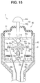
- Fig. 15 is a cross-sectional view showing an internal configuration of an operation portion;
- Fig. 16 is a perspective view showing the internal configuration of the operation portion;
- Fig. 17 is a cross-sectional view showing arrangement of tension springs in the operation portion;
- Fig. 18 is a cross-sectional view showing the tension spring, one end of which is hooked to a spring hooking member in which a bending operation wire is inserted, and the other end of which is hooked to a projecting portion of a frame portion;
- Fig. 14 is a plan view showing a configuration of an endoscope
- Fig. 15 is a cross-sectional view showing an internal configuration of an operation portion
- Fig. 16 is a perspective view showing the internal configuration of the operation portion
- Fig. 17 is a cross-sectional view showing arrangement of tension springs in the operation
- FIG. 19 is a cross-sectional view showing arrangement of the tension springs in the operation portion according to another aspect different from Fig. 17 ;
- Fig. 20 is a cross-sectional view showing arrangement of the tension springs in the operation portion according to another aspect different from Figs. 17 and 19 ;
- Fig. 21 is a cross-sectional view showing a configuration of a bending operation unit provided in the operation portion according to a first modification;
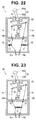
- Fig. 22 is a cross-sectional view showing a configuration of the tension springs of the bending operation unit provided in the operation portion according to a second modification;
- Fig. 23 is a cross-sectional view showing a configuration of the tension springs of the bending operation unit provided in the operation portion according to a third modification;
- Fig. 24 is a cross-sectional view showing a configuration of the tension springs of the bending operation unit provided in the operation portion according to a fourth modification
- Fig. 25 is a cross-sectional view showing a configuration of the tension springs of the bending operation unit provided in the operation portion according to a fifth modification
- Fig. 26 is a cross-sectional view showing a configuration of the tension springs of the bending operation unit provided in the operation portion according to a sixth modification
- Fig. 27 is a cross-sectional view showing a configuration of the tension springs of the bending operation unit provided in the operation portion according to a seventh modification
- Fig. 28 is a cross-sectional view showing a configuration of the endoscope in which a joystick lever is provided on a side portion of the operation portion, according to an eighth modification.
- a joystick lever 50 different from the angle lever 14 of the first embodiment is arranged on a proximal end part of the operation portion 3 as a bending operation member for remotely operating the bending portion 12. Further, on a side of the proximal end part of the operation portion 3 here, a grip 10 from which the flexible cable 6 extends is extendedly provided.
- the endoscope 1 of the present embodiment is configured so that the bending portion 12 is bendable in the four directions of upward, downward, right and left directions by an inclination operation of the joystick lever 50 provided on the proximal end portion of the operation portion 3.
- the housing 8 of the operation portion 3 is provided with a bending operation unit 60 similarly to the first embodiment.
- the bending operation unit 60 has mainly the joystick lever 50, a rubber boot 51 which covers the joystick lever 50 in a state that one end portion of the joystick lever 50 projects from the rubber boot 51, a cylinder-shaped frame portion 52, one end of which is blocked and an opening of which at the other end is covered with the rubber boot 51, a wire pulling portion 53 which is movably arranged in the frame portion 52 and which is a rotation member here, and an amount-of-operation-force reducing portion 30 provided between the wire pulling portion 53 and a bottom portion 52a of the frame portion 52 and having a configuration similar to that of the first embodiment.
- the joystick lever 50 has a rod 50b, and a hemisphere-shaped finger-putting portion 50a at one end portion of the rod 50b projecting and exposed from the rubber boot 51.
- the other end of the rod 50b of the joystick lever 50 on the frame portion 52 side is connected to a sphere 54.
- a bar-shaped connection portion 53a extended from a center of a top of the wire pulling portion 53 is connected on a side opposite to the side where the rod 50b of the joystick lever 50 is connected.
- the sphere 54 is movably held by a sphere receiving portion 52b provided in the frame portion 52. That is, the sphere 54 and the sphere receiving portion 52b of the frame portion 52 constitute a so-called boll joint. Thereby, a configuration is made in which, by performing an inclination operation of the joystick lever 50, the wire pulling portion 53 rotates around a center of the sphere 54 and is inclined.
- the frame portion 52 four holding arm portions 52c are extendedly arranged so as to form a cross shape arranged being extended from an inner circumferential face in an inner diameter direction, and the sphere receiving portion 52b is provided at a center of a crossing of the four holding arm portions 52c. That is, the sphere receiving portion 52b is held at a center of the frame portion 52 by the four holding arm portions 52c.
- the wire pulling portion 53 is extendedly arranged with four pulling arm portions 53b are so as to form a cross shape, and a fixation hole 53c for fixing an end portion of a bending operation wire 19 is made near an end of each of the pulling arm portions 53b.
- fixation members 19a provided on end portions of the corresponding bending operation wires 19 being inserted in and hooked to the fixation holes 53c, one end of each of the bending operation wires 19 is connected to each of the pulling arm portions 53b.
- each bending operation wire 19 is inserted in any of four coil pipes 19b fixed such that one end projects from the bottom portion 52a of the frame portion 52, and is extended to the bending portion 12.
- each coil pipe 19b is arranged in the rigid tube 13 of the insertion portion 2.
- the bending portion 12 is bent to upward, downward, right or left (UP/RL) by the plurality of bending pieces (not shown) provided inside the bending portion 12 rotating according to pulled/slackened states of the four bending operation wires 19.
- a sphere receiving portion 53d is provided at a central part of the wire pulling portion 53.
- the sphere receiving portion 53d movably holds a sphere 31a provided on an end portion of the cylinder portion 31 on an upper part side of the amount-of-operation-force reducing portion 30 on the sheet surface of Fig. 15 (a proximal end side of the endoscope 1). That is, the sphere 31a and the sphere receiving portion 53d constitute a so-called boll joint.
- the amount-of-operation-force reducing portion 30 is also provided with a sphere 32a at an end portion of the rod portion 32 on a lower part side on the sheet surface of Fig. 15 (a distal end side of the endoscope 1).
- the sphere 32a is movably held by the sphere receiving portion 52b provided at a center of the bottom portion 52a of the frame portion 52. That is, the sphere 32a and the sphere receiving portion 52b constitute a so-called boll joint.
- the amount-of-operation-force reducing portion 30 rotates around a center of the sphere 31 a of the cylinder portion 31 and a center of the sphere 32a of the rod portion 32 when the wire pulling portion 53 inclines by an operation of the joystick lever 50.
- the amount-of-operation-force reducing portion 30 is configured so as to be inclined at a predetermined angle in a direction opposite to a direction in which the wire pulling portion 53 is inclined by the operation of the joystick lever 50 then.
- any of the four bending operation wires 19 is pulled or slackened according to inclination of the four pulling arm portions 53b of the wire pulling portion 53. Then, the bending portion 12 is bent in the upward, downward, right or left direction by the plurality of bending pieces (not shown) provided inside the bending portion 12 rotating in a predetermined direction according to pulled/slackened states of the four bending operation wires 19.
- the amount-of-operation-force reducing portion 30 of the present embodiment is inclined at a predetermined angle in a predetermined direction in conjunction with a motion of the wire pulling portion 53, by an operation of the joystick lever 50, and the cylinder portion 31 which has received urging force of the compression springs 39 is urged in a direction against the rod portion 32. That is, the wire pulling portion 53 inclined in conjunction with the operation of the joystick lever 50 for performing a bending operation of the bending portion 12 is given the urging force from the amount-of-operation-force reducing portion 30 in the inclination direction.
- the amount-of-operation-force reducing portion 30 gives urging force of the compression springs 39 in the direction in which the wire pulling portion 53 is inclined, to reduce the amount of operation force of the joystick lever 50.
- the urging force is added from the amount-of-operation-force reducing portion 30 in the direction in which the wire pulling portion 53 is inclined.
- the sphere 54 which is interposed between the joystick lever 50 and the wire pulling portion 53 and is movably held by the sphere receiving portion 52b rotates around its center.
- the center of the sphere 54 interposed between the joystick lever 50 and the wire pulling portion 53 corresponds to the center Oa of the rotation shaft 21 of the pulley unit 22;
- the center of the sphere 31 a of the cylinder portion 31 of the amount-of-operation-force reducing portion 30 corresponds to the center Ob of the shaft body 23 on the pulley unit 22 side;
- the center of the sphere 32a of the rod portion 32 of the amount-of-operation-force reducing portion 30 corresponds to the center Oc of the shaft body 24 on the housing 8 side.
- rotation torque around the center of the sphere 54 movably held by the sphere receiving portion 52b which is given from the amount-of-operation-force reducing portion 30, increases as an absolute value of a rotation angle of the sphere 54 at time when the joystick lever 50 is inclined increases, because a rotation component which occurs around the center of the sphere 54 increases as the absolute value increases.
- the rotation torque given from the amount-of-operation-force reducing portion 30 increases as the absolute value of the rotation angle of the sphere 54 by an operation of the joystick lever 50 increases, and offsets and reduces the operation torque required at time of operating the joystick lever 50 by an amount of force of the rotation torque.
- an operation range of the joystick lever 50 is a range within which the bending portion 12 is operated at a set maximum bending angle, and the rotation angle of the sphere 54 is between 0° at the neutral position (neutral) at which the bending portion 12 is not bending-operated and ⁇ 90°, including 0° and excluding ⁇ 90°.
- the endoscope 1 of the present embodiment also, it is possible to, at the time of performing a bending operation of the bending portion 12, cause a rotation component from urging force from the compression springs 39 of the amount-of-operation-force reducing portion 30 to give rotation torque to the wire pulling portion 53 in the rotation direction of the sphere 54 which rotates in response to an inclination operation of the joystick lever 50, offset the operation torque required at the time of operating the joystick lever 50 by the amount of force of the rotation torque and reduce the amount of operation force of the joystick lever 50, similarly to the first embodiment.
- the endoscope 1 also has an advantage that, since the force for performing a bending operation of the bending portion 12 by the joystick lever 50 is reduced and relieved, bending operability is improved, and it becomes easier to perform a slight operation.
- the endoscope 1 of the present embodiment also reduces the amount of operation force of the joystick lever 50, which is an operation member for performing a bending operation of the bending portion 12, prevents a user from being tired, and makes it possible to perform a slight bending operation.
- two bending operation wires 19 form a pair of pulling and slackening states according to a bending state of the bending portion 12 because the bending portion 12 is bending-operated by pulling/slackening the four bending operation wires 19; and, especially when a loosened bending operation wire 19 is pulled, the joystick lever 50 falls down swiftly and cannot be smoothly operated.
- the endoscope 1 gives an uncomfortable feeling to a user at the time of performing a bending operation.
- a loosened bending operation wire 19 is pulled suddenly at time of changing a bending direction of the bending portion 12, the bending portion 12 cannot move continuously and smoothly, and it becomes difficult to determine a direction at time of performing photographing aiming at an examination target site and an endoscopic image is instantaneously switched, that is, so-called image jump occurs by the bending portion 12 poppingly moving intermittently.
- the endoscope 1 of the present embodiment is configured such that an elastic member is provided as a pulling member for providing a state of being continuously tensioned so that each of the bending operation wires 19 is not loosened.
- the endoscope 1 here is provided with four tension springs 61 as pulling springs which are elastic members for pulling and tensioning the bending operation wires 19 in an outer diameter direction of the frame portion 52 so that each bending operation wire 19 is in a predetermined direction, for example, in such a manner that the tension springs 61 have a predetermined angle relative to longitudinal directions of the pulled bending operation wires 19, in the frame portion 52 of the bending operation unit 60 provided in the operation portion 3.
- the elastic members are not limited to the tension springs 61, and rubber may be used.
- each tension spring 61 is hooked to a body portion of a spring hooking member 62, and the other end is hooked and fixed to a projecting member 63 having a hole portion and arranged on an inner circumference of the frame portion 52.
- the spring hooking member 62 has a hole portion 62a in which the bending operation wire 19 is inserted, and is slidable along the bending operation wire 19. Further, a circumference groove 62b for hooking one end of the tension spring 61 is formed in the body portion of the spring hooking member 62.
- each bending operation wire 19 is in the state of being continuously tensioned by being pulled in the outer diameter direction of the frame portion 52 by the tension spring 61.
- a bending operation wire 19 in a slackened state is not in a state of being loosened according to a bending state of the bending portion 12, and it does not happen that the joystick lever 50 falls down swiftly. Therefore, it becomes possible to operate the joystick lever 50 smoothly, and it does not happen that an uncomfortable feeling is given to a user at the time of performing a bending operation due to operability of the smooth bending operation of the bending portion 12 by the joystick lever 50.
- the bending portion 12 can bend continuously and smoothly even if the bending operation wire 19 is pulled suddenly at the time of changing the bending direction of the bending portion 12.
- the endoscope 1 it is easy to determine a direction at the time of performing photographing aiming at an examination target site, and the bending portion 12 can smoothly bend. Therefore, it is possible to prevent an endoscopic image from being instantaneously switched, that is, occurrence of the so-called image jump.
- each tension springs 61 is not limited to the arrangement/configuration of pulling each bending operation wire 19 in the outer diameter direction of the frame portion 52 as shown in Fig. 17 in order that each bending operation wire 19 is in the state of being continuously tensioned, but the arrangement/configuration can be freely changed.
- positions on the frame portion 52 to which the tension springs 61 are fixed may be changed as shown in Fig. 19 or 20 to change a pulling direction of each bending operation wire 19 by each tension springs 61.
- the present modification is an example of making it possible to adjust the rotation torque given from the amount-of-operation-force reducing portion 30 according to an operation angle of the joystick lever 50.
- the wire pulling portion 53 here is provided with a protrusion portion 53e projecting to a lower part side on the sheet surface of Fig. 21 and from which the four pulling arm portions 53b described above are extendedly arranged, at a central part.
- a female screw hole 53f is formed from the lower part side.
- a male screw portion 55a of a sphere receiving portion 55 which movably holds the sphere 31a provided at the end portion of the cylinder portion 31 of the amount-of-operation-force reducing portion 30 is screwed in the female screw hole 53f of the protrusion portion 53e.
- the male screw portion 55a is provided such that it projects to an upper part side on the sheet surface of Fig. 21 from a center of a surface of the sphere receiving portion 55.
- the sphere 31a and the sphere receiving portion 55 constitutes a so-called ball joint, and the amount-of-operation-force reducing portion 30 here is configured so as to rotate around the center of the sphere 31a of the cylinder portion 31.
- a length L1 which is a distance of separation between the center of the sphere 54 interposed among the joystick lever 50, the sphere 54 and the wire pulling portion 53 and the center of the sphere 31a of the cylinder portion 31 of the amount-of-operation-force reducing portion 30, by changing a screwed amount of the male screw portion 55a of the sphere receiving portion 55 screwed into the female screw hole 53f formed in the protrusion portion 53e of the wire pulling portion 53.
- a length L2 which is a distance of separation between the center of the sphere 31a of the cylinder portion 31 and the center of the sphere 32a of the rod portion 32, is changed, accompanying change in the screwed amount of the male screw portion 55a screwed into the female screw hole 53f.
- a length (L1+L2) which is a distance of separation between the center of the sphere 54 interposed among the joystick lever 50, the sphere 54 and the wire pulling portion 53 and the center of the sphere 32a of the rod portion 32 of the amount-of-operation-force reducing portion 30, is not changed but is constant.
- the endoscope 1 of the present modification configured as described above, it is possible to increase the rotation torque given from the amount-of-operation-force reducing portion 30 according to an operation angle of the joystick lever 50, by extending the length L1, which is the distance of separation between the center of the sphere 54 interposed among the joystick lever 50, the sphere 54 and the wire pulling portion 53 and the center of the sphere 31a of the cylinder portion 31 of the amount-of-operation-force reducing portion 30.
- the urging force of the compression springs 39 increases by shortening the length L2, which is the distance of separation between the center of the sphere 31 a of the cylinder portion 31 and the center of the sphere 32a of the rod portion 32 in the amount-of-operation-force reducing portion 30.
- the endoscope 1 of the present modification is adapted to make it possible to adjust the rotation torque given from the amount-of-operation-force reducing portion 30 only by changing the screwed amount of the male screw portion 55a of the sphere receiving portion 55 screwed into the female screw hole 53f formed in the protrusion portion 53e of the wire pulling portion 53, and, thereby, it is possible to optimize the amount of operation force of the joystick lever 50.
- the present modification is an example of an arrangement of the tension springs 61 for causing the bending operation wires 19 to be in the state of being continuously tensioned without being loosened.
- the tension spring 61 may be arranged so that the bending operation wire 19 is pulled to the outer diameter direction of the frame portion 52, between the coil pipes 19b in which the bending operation wire 19 is inserted, as shown in Fig. 22 .
- the present modification is an example about a configuration of the tension spring 61 for causing the bending operation wire 19 to be in the state of being continuously tensioned without being loosened.
- Such a configuration is also possible that one tension spring 61 both ends of which are hooked to the spring hooking members 62 is provided so as to connect two paired bending operation wires 19 for performing an upward/downward-direction or right/left-direction bending operation of the bending portion 12 is provided between the coil pipes 19b in which each bending operation wire 19 is inserted, so that the two bending operation wires 19 are in the state of being continuously tensioned without being loosened, as shown in Fig. 23 .
- the present modification is also an example about a configuration of the tension spring 61 for causing the bending operation wire 19 to be in the state of being continuously tensioned without being loosened.
- tension spring 61 is interposed between the coil pipes 19b in which the bending operation wire 19 is inserted, along a longitudinal direction of the bending operation wire 19 to cause the bending operation wire 19 to be in the state of being continuously tensioned without being loosened, as shown in Fig. 24 .
- the present modification is also an example about a configuration of the tension spring 61 for causing the bending operation wire 19 to be in the state of being continuously tensioned without being loosened.
- Such a configuration is also possible that, between the coil pipes 19b in which each bending operation wire 19 is inserted, the tension spring 61 is provided such that it becomes slidable relative to the bending operation wire 19 by hooking both ends to the spring hooking members 62, and a cylinder-shaped member 64 is provided being sandwiched between the bending operation wire 19 and the tension spring 61, so that the bending operation wire 19 is caused to be in the state of being continuously tensioned without being loosened, as shown in Fig. 25 .
- the present modification is also an example about a configuration of the tension spring 61 for causing the bending operation wire 19 to be in the state of being continuously tensioned without being loosened.
- a fixing portion 65 for fixing one end of the tension spring 61 to the bending operation wire 19 is provided without providing the spring hooking members 62 to cause the bending operation wire 19 to be in the state of being continuously tensioned without being loosened, as shown in Fig. 26 .
- abrasion between the bending operation wire 19 and the spring hooking members 62 is prevented, and durability is improved.
- the present modification is also an example about a configuration of the tension spring 61 for causing the bending operation wire 19 to be in the state of being continuously tensioned without being loosened.
- the present modification is an example about arrangement/configuration of the joystick lever 50 provided on the bending portion 12.
- the endoscope 1 may be configured being provided with the joystick lever 50 on one side portion of the operation portion 3 as shown in Fig. 28 .
- a pulley unit 22 for changing the direction of each bending operation wire 19 in the operation portion 3 is provided, and the tension springs 61 for pulling the pulley units 22 to a proximal end side of the operation portion 3 are provided so as to cause the bending operation wire 19 to be in the state of being continuously tensioned without being loosened.
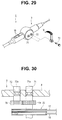
- a first rotation shaft 71 and a second rotation shaft 72 are provided on the operation portion 3, and the angle lever 14 is selectively attachable to and detachable from the first and second rotation shafts 71 and 72, as shown in Figs. 29 and 30 .
- Fig. 29 is an exploded perspective view showing a bending operation lever attachable to and detachable from an operation portion of an endoscope; and Fig. 30 is a cross-sectional view showing a configuration of two rotation shafts which the bending operation lever is selectively attachable to and detachable from.
- Screw holes 71 a and 72a for screwing and fixing a fixing screw 73 for fixing the angle lever 14 are formed in the first and second rotation shafts 71 and 72, respectively.
- the pulley unit 22 is provided on the first rotation shaft 71, and a flat-toothed gear 74 is interposed between the pulley unit 22 and the housing 8 of the operation portion 3. Further, the second rotation shaft 72 is provided with a flat-toothed gear 75 engaged with the gear 74 of the first rotation shaft 71.
- the bending operation direction of the bending portion 12 by the angle lever 14 can be selected by fixing the angle lever 14 to the first rotation shaft 71 or the second rotation shaft 72 selectively.
- the pulley unit 22 rotates in a direction corresponding to a rotation direction according to a direction of an operation by the angle lever 14.
- the pulley unit 22 rotates in a direction opposite to a rotation direction according to a direction of an operation by the angle lever 14, by the gears 74 and 75.
- the endoscope 1 makes it possible to select the direction of a bending operation of the bending portion 12 by the angle lever 14 according to which the user wishes.
Landscapes
- Health & Medical Sciences (AREA)
- Life Sciences & Earth Sciences (AREA)
- Physics & Mathematics (AREA)
- Surgery (AREA)
- Optics & Photonics (AREA)
- Engineering & Computer Science (AREA)
- Biomedical Technology (AREA)
- Molecular Biology (AREA)
- Pathology (AREA)
- Radiology & Medical Imaging (AREA)
- Veterinary Medicine (AREA)
- Biophysics (AREA)
- Public Health (AREA)
- Heart & Thoracic Surgery (AREA)
- Medical Informatics (AREA)
- Nuclear Medicine, Radiotherapy & Molecular Imaging (AREA)
- Animal Behavior & Ethology (AREA)
- General Health & Medical Sciences (AREA)
- General Physics & Mathematics (AREA)
- Astronomy & Astrophysics (AREA)
- Mechanical Engineering (AREA)
- Instruments For Viewing The Inside Of Hollow Bodies (AREA)
- Endoscopes (AREA)
Abstract
Description
- The present invention relates to an endoscope which has a bending portion at a distal end side of an insertion portion and in which a bending operation of the bending portion is performed by a bending operation member provided on an operation portion on a hand side.
- Recently, endoscopes have been widely used in a medical field and an industrial field. In some endoscopes, an elongated insertion portion is flexible, and, generally, a bending portion which can be freely bending-operated in a predetermined direction according to a user's operation at hand is provided on a distal end side of the insertion portion.
- In such an endoscope having the insertion portion which is provided with the bending portion, it is possible to, by causing the bending portion to bend, change an observation direction of an observation optical system provided at a distal end portion located on the more distal end side of the insertion portion than the bending portion so that examination for a wide range can be performed.
- Conventional endoscopes are configured such that a bending operation of the bending portion is performed on a hand side by the operation member of a lever type, a joystick type or the like which is provided on the operation portion, for example, as disclosed in Japanese Patent Application Laid-Open Publication No.
S62-38411 2009-89955 - In the conventional endoscopes as disclosed in Japanese Patent Application Laid-Open Publication No.
S62-38411 2009-89955 - Therefore, the conventional endoscopes have a problem that, at time of performing a bending operation of the bending portion, a user is caused to be tired, and it is difficult to perform a slight bending operation.
- Thus, the present invention has been made in view of the above situation, and an object of the present invention is to provide an endoscope which reduces an amount of operation force of the operation member for performing a bending operation of the bending portion to prevent a user from being tired and make it possible to perform a slight bending operation.
- An endoscope of an aspect in the present invention includes: an insertion portion provided with a bending portion at a distal end part; an operation portion coupled to the insertion portion; operation wires insertedly arranged inside the insertion portion and the operation portion, the operation wires causing the bending portion to bend by being pulled/slackened; an operation member provided on the operation portion, the operation member performing a bending operation of the bending portion; a rotation member provided in the operation portion, the rotation member pulling/slackening the operation wires by rotating in conjunction with an operation of the operation member; and an amount-of-operation-force reducing portion giving rotation torque in a direction in which the rotation member rotates to reduce an amount of operation force of the operation member, in response to an operation of the operation member.
- According to the present invention described above, it is possible to provide an endoscope which reduces an amount of operation force of an operation member for performing a bending operation of a bending portion to prevent a user from being tired and make it possible to perform a slight bending operation.
-
-
Fig. 1 is a perspective view showing a general configuration of an endoscope of an aspect according to a first embodiment of the present invention; -
Fig. 2 is a cross-sectional view showing an internal configuration of an operation portion according to the first embodiment of the present invention; -
Fig. 3 is a partial cross-sectional view showing a configuration of a pulley unit and an amount-of-operation-force reducing portion which are provided in the operation portion according to the first embodiment of the present invention; -
Fig. 4 is a diagram illustrating action of the amount-of-operation-force reducing portion in a state that a bending portion is bent to an upper part side according to the first embodiment of the present invention; -
Fig. 5 is a diagram illustrating action of the amount-of-operation-force reducing portion in a state that the bending portion is bent to a lower part side according to the first embodiment of the present invention; -
Fig. 6 is a partial cross-sectional view illustrating the action of the amount-of-operation-force reducing portion in the state that the bending portion is bent to the upper part side according to the first embodiment of the present invention; -
Fig. 7 is a diagram for illustrating a principle of reducing an amount of bending operation force according to the first embodiment of the present invention; -
Fig. 8 is a curve graph showing relationships among operation torque of an angle lever, rotation torque and a rotation angle according to the first embodiment of the present invention; -
Fig. 9 is a curve graph showing a relationship between actual operation torque obtained by offsetting the operation torque of the angle lever with the rotation torque and the rotation angle, according to the first embodiment of the present invention; -
Fig. 10 is a cross-sectional view showing an internal configuration of an operation portion in which the pulley unit is provided with a tension spring, according to a modification according to the first embodiment of the present invention; -
Fig. 11 is a side view showing the configuration in which the pulley unit provided in the operation portion is provided with the tension spring, according to the modification according to the first embodiment of the present invention; -
Fig. 12 is a diagram illustrating action of the tension spring in the state that the bending portion is bent to the upper part side, according to the modification according to the first embodiment of the present invention; -
Fig. 13 is a diagram illustrating action of the tension spring in the state that the bending portion is bent to the lower part side, according to the modification according to the first embodiment of the present invention; -
Fig. 14 is a plan view showing a configuration of an endoscope of another aspect according to a second embodiment of the present invention; -
Fig. 15 is a cross-sectional view showing an internal configuration of an operation portion according to the second embodiment of the present invention; -
Fig. 16 is a perspective view showing the internal configuration of the operation portion according to the second embodiment of the present invention; -
Fig. 17 is a cross-sectional view showing arrangement of tension springs in the operation portion according to the second embodiment of the present invention; -
Fig. 18 is a cross-sectional view showing the tension spring, one end of which is hooked to a spring hooking member in which a bending operation wire is inserted and the other end of which is hooked to a projecting portion of a frame portion according to the second embodiment of the present invention; -
Fig. 19 is a cross-sectional view showing arrangement of the tension springs in the operation portion according to another aspect different fromFig. 17 according to the second embodiment of the present invention; -
Fig. 20 is a cross-sectional view showing arrangement of the tension springs in the operation portion according to another aspect different fromFigs. 17 and19 according to the second embodiment of the present invention; -
Fig. 21 is a cross-sectional view showing a configuration of a bending operation unit provided in the operation portion according to a first modification according to the second embodiment of the present invention; -
Fig. 22 is a cross-sectional view showing a configuration of the tension springs of the bending operation unit provided in the operation portion according to a second modification according to the second embodiment of the present invention; -
Fig. 23 is a cross-sectional view showing a configuration of the tension springs of the bending operation unit provided in the operation portion according to a third modification according to the second embodiment of the present invention; -
Fig. 24 is a cross-sectional view showing a configuration of the tension springs of the bending operation unit provided in the operation portion according to a fourth modification according to the second embodiment of the present invention; -
Fig. 25 is a cross-sectional view showing a configuration of the tension springs of the bending operation unit provided in the operation portion according to a fifth modification according to the second embodiment of the present invention; -
Fig. 26 is a cross-sectional view showing a configuration of the tension springs of the bending operation unit provided in the operation portion according to a sixth modification according to the second embodiment of the present invention; -
Fig. 27 is a cross-sectional view showing a configuration of the tension springs of the bending operation unit provided in the operation portion according to a seventh modification according to the second embodiment of the present invention; -
Fig. 28 is a cross-sectional view showing a configuration of the endoscope in which a joystick lever is provided on a side portion of the operation portion, according to an eighth modification according to the second embodiment of the present invention; -
Fig. 29 is an exploded perspective view showing a bending operation lever attachable to and detachable from an operation portion of an endoscope according to a reference example; and -
Fig. 30 is a cross-sectional view showing a configuration of two rotation shafts which the bending operation lever is selectively attachable to and detachable from, according to the reference example. - The present invention will be described below with use of drawings.
- Note that attention should be paid to that, in description below, the drawings based on embodiments described below are schematic, and a relationship between thickness and width of each portion, a ratio among thicknesses of respective portions and the like are different from an actual relationship, ratio and the like, and that there may be a case where a portion having a different size relationship and ratio is included among the drawings.
- First, an embodiment of an endoscope of an aspect of the present invention will be described below based on drawings. Note that, though description will be made below on a rigid endoscope in which an insertion portion is rigid, as an example, the technique is not limited to the rigid endoscope but is also applicable to a flexible endoscope in which the insertion portion is a flexible tube.
- First, a first embodiment of the present invention will be described.
-
Figs. 1 to 13 relate to the first embodiment of the present invention.Fig. 1 is a perspective view showing a general configuration of an endoscope;Fig. 2 is a cross-sectional view showing an internal configuration of an operation portion;Fig. 3 is a partial cross-sectional view showing a configuration of a pulley unit and an amount-of-operation-force reducing portion which are provided in the operation portion;Fig. 4 is a diagram illustrating action of the amount-of-operation-force reducing portion in a state that a bending portion is bent to an upper part side;Fig. 5 is a diagram illustrating action of the amount-of-operation-force reducing portion in a state that a bending portion is bent to a lower part side;Fig. 6 is a partial cross-sectional view illustrating the action of the amount-of-operation-force reducing portion in the state that the bending portion is bent to the upper part side;Fig. 7 is a diagram for illustrating a principle of reducing an amount of bending operation force;Fig. 8 is a curve graph showing relationships among operation torque of an angle lever, rotation torque and a rotation angle;Fig. 9 is a curve graph showing a relationship between actual operation torque obtained by offsetting the operation torque of the angle lever with the rotation torque and the rotation angle;Fig. 10 is a cross-sectional view showing an internal configuration of an operation portion in which the pulley unit is provided with a tension spring, according to a modification;Fig. 11 is a side view showing the configuration in which the pulley unit provided in the operation portion is provided with the tension spring, according to the modification;Fig. 12 is a diagram illustrating action of the tension spring in the state that the bending portion is bent to the upper part side, according to the modification; andFig. 13 is a diagram illustrating action of the tension spring in the state that the bending portion is bent to the lower part side, according to the modification. - As shown in
Fig. 1 , anendoscope 1 is mainly configured having anelongated insertion portion 2, anoperation portion 3 coupled to a proximal end of theinsertion portion 2, a light guide connector 4 connected to a light source apparatus not shown, and avideo connector 5 connected to a video system center not shown. - Note that, in the
endoscope 1, theoperation portion 3 and the light guide connector 4 are connected via aflexible cable 6 as a universal code, and the light guide connector 4 and thevideo connector 5 are connected via a communication cable 7. - Mainly a
distal end portion 11 and abending portion 12 which are formed by metallic members such as stainless steel members, and arigid tube 13 which is a metal tube such as a stainless steel tube are coupled to theinsertion portion 2 in that order from a distal end side. Theinsertion portion 2 is a part to be inserted into a body, and cables to be described later and a light guide are included inside theinsertion portion 2. - The
operation portion 3 is provided with anangle lever 14 as a bending operation member for remotely controlling thebending portion 12, andvarious switches 16 for operating the light source apparatus (not shown), the video system center (not shown) and the like. Theangle lever 14 is, here, bending operation means capable of operating thebending portion 12 of theinsertion portion 2 in two directions of upward and downward directions. Note that a configuration is also possible in which two angle levers are provided so as to bend thebending portion 12 in four directions of upward, downward, right and left directions. - The
bending portion 12 of theinsertion portion 2 is provided with a plurality of bending pieces not shown, and thebending portion 12 is bent by the plurality of bending pieces being rotated bybending operation wires Figs. 2 and 3 ). Further, thebending portion 12 is provided with abending rubber 12a as an outer cover which covers the plurality of bending pieces. - As shown in
Figs. 2 and 3 , apulley unit 22 which is a rotation member fixed to arotation shaft 21 connected to theangle lever 14 is rotatably provided in ahousing 8 of theoperation portion 3. In thepulley unit 22, afirst pulley 22a and asecond pulley 22b are arranged midway of therotation shaft 21 side by side. - A rear end of the first
bending operation wire 17 is fixed to thefirst pulley 22a. The firstbending operation wire 17 is pulled by thefirst pulley 22a being rotated in a clockwise direction on the sheet surface ofFig. 2 . At this time, the bendingportion 12 is bent to an upper part (UP) side by the plurality of bending pieces (not shown) being rotated in response to pulling of the firstbending operation wire 17. - A rear end of the second
bending operation wire 18 is fixed to thesecond pulley 22b. The secondbending operation wire 18 is pulled by thesecond pulley 22b being rotated in the clockwise direction on the sheet surface ofFig. 2 . At this time, the bendingportion 12 is bent to a lower part (DOWN) side by the plurality of bending pieces (not shown) being rotated in response to pulling of the secondbending operation wire 18. - Note that the first
bending operation wire 17 and the secondbending operation wire 18 are inserted incoil pipes rigid tube 13 of theinsertion portion 2 from the distal end side of theoperation portion 3. - Further, the
operation portion 3 is provided with an amount-of-operation-force reducing portion 30 as bending operation assisting means for reducing an amount of operation force by theangle lever 14. The amount-of-operation-force reducing portion 30 is rotatably provided between thepulley unit 22 and thehousing 8 of theoperation portion 3. - More specifically, the amount-of-operation-
force reducing portion 30 has acylinder portion 31, arod portion 32, and compression springs 39 which are elastic members provided between thecylinder portion 31 and therod portion 32 as shown inFig. 3 . - The
cylinder portion 31 has aconnection portion 33, anoutward flange 34 and atube portion 35. Here, theconnection portion 33 of thecylinder portion 31 is rotatably supported by ashaft body 23 fixed to an edge part of one face of thefirst pulley 22a of thepulley unit 22. - The
rod portion 32 has arod 36, anoutward flange 37 and aconnection portion 38. Theconnection portion 38 of therod portion 32 is rotatably supported by ashaft body 24 fixed to aprotrusion portion 9 provided on thehousing 8 of theoperation portion 3. Therod 36 of therod portion 32 is inserted in thetube portion 35 of thecylinder portion 31, and the compression springs 39 are arranged between the respectiveoutward flanges tube portion 35 and therod 36. - In the amount-of-operation-
force reducing portion 30, thecylinder portion 31 and therod portion 32 can freely advance or retreat so as to be guided to go straight, by insertion of therod 36 into therod portion 32, and are urged by the compression springs 39 in directions in which they are mutually separated. - Note that, when the bending
portion 12 is in a state of a neutral position (neutral) in which the bendingportion 12 is straight without being bent, therotation shaft 21 of thepulley unit 22, theshaft body 23 on apulley unit 22 side and theshaft body 24 on ahousing 8 side are sequentially arranged on a straight line side by side. That is, in the state of the neutral position (neutral) in which the bendingportion 12 is straight without being bent, theshaft body 23 is arranged between therotation shaft 21 and theshaft body 24. - As described above, here, arrangement of each of the
rotation shaft 21 of thepulley unit 22, theshaft body 23 on thepulley unit 22 side and theshaft body 24 on thehousing 8 side is set so that they are in line with one another when the bendingportion 12 is in the straight-line state without being bent. - Note that the
rotation shaft 21 of thepulley unit 22, theshaft body 23 on thepulley unit 22 side and theshaft body 24 on thehousing 8 side may be arranged at any positions if they are arranged so as to be in line with one another when the bendingportion 12 is at the neutral position (neutral) of not being bending-operated. Here, as an example, such a configuration is made that therotation shaft 21 and therespective shaft bodies Fig. 2 , which is a front/rear direction of theendoscope 1. - In the
endoscope 1 of the present embodiment configured as described above, the amount of operation force of theangle lever 14 is reduced by the amount-of-operation-force reducing portion 30 provided in theoperation portion 3 at time of operating theangle lever 14 to perform a bending operation of the bendingportion 12. - More specifically, as shown in
Fig. 4 , at time of bending the bendingportion 12 to the upper part side by inclining theangle lever 14 to a proximal end side, which is a hand side, thepulley unit 22 rotates in one direction around therotation shaft 21, the clockwise direction on the sheet surface ofFig. 4 , in conjunction with theangle lever 14. Then, accompanying the rotation of thepulley unit 22, the amount-of-operation-force reducing portion 30 is inclined to a distal end side of theendoscope 1. - That is, in the amount-of-operation-
force reducing portion 30, thecylinder portion 31 rotates around theshaft body 23 on thepulley unit 22 side, and therod portion 32 rotates around theshaft body 24 on thehousing 8 side. At this time, in the amount-of-operation-force reducing portion 30, thecylinder portion 31 which has received urging force of the compression springs 39 is urged into a direction of being separated from the rod portion 32 (as a reference, a state ofFig. 3 transitions to a state ofFig. 6 ). - On the other hand, as shown in
Fig. 5 , at time of bending the bendingportion 12 to the lower part side by inclining theangle lever 14 to the distal end side, thepulley unit 22 rotates in one direction around therotation shaft 21, the counterclockwise direction on the sheet surface ofFig. 5 , in conjunction with theangle lever 14. Here, accompanying the rotation of thepulley unit 22, the amount-of-operation-force reducing portion 30 is inclined to a proximal end side of theendoscope 1, and thecylinder portion 31 which has received the urging force of the compression springs 39 of the amount-of-operation-force reducing portion 30 is urged into the direction of being separated from the rod portion 32 (the state ofFig. 3 transitions to the state ofFig. 6 ). - In this way, the urging force is given from the amount-of-operation-
force reducing portion 30 in a direction in which thepulley unit 22 rotates, thepulley unit 22 rotating in conjunction with theangle lever 14 which performs a bending operation of the bendingportion 12. That is, at the time of performing a bending operation of the bendingportion 12 by theangle lever 14, the amount-of-operation-force reducing portion 30 gives predetermined rotation torque (added torque) to thepulley unit 22 to reduce the amount of operation force of theangle lever 14. - Note that, since the
rotation shaft 21 of thepulley unit 22, theshaft body 23 on thepulley unit 22 side and theshaft body 24 on thehousing 8 side are located in line with one another when the bendingportion 12 is at the neutral position (neutral) of not being bending-operated, the predetermined rotation torque from the amount-of-operation-force reducing portion 30 to thepulley unit 22 is not given. - In other words, the compression springs 39 of the amount-of-operation-
force reducing portion 30 are arranged so as to urge force in a direction to a rotation center of therotation shaft 21 so that rotation torque is not given to thepulley unit 22 when the bendingportion 12 is in the neutral-position state in which the bendingportion 12 is straight without being bent. - Here, description will be made on the principle of, at the time of performing a bending operation of the bending
portion 12 by theangle lever 14, giving rotation torque from the amount-of-operation-force reducing portion 30 to thepulley unit 22 to reduce the amount of operation force of theangle lever 14, based onFigs. 7 to 9 . - Note that, though, for example, the action of reducing the amount of operation force of the
angle lever 14 when theangle lever 14 is inclined to the distal end side at the time of performing a bending operation of the bendingportion 12 is shown as an example, as shown inFig. 7 , the action of reducing the amount of operation force of theangle lever 14 similarly occurs when theangle lever 14 is inclined to the proximal end side also. - First, rotation torque M given to the
pulley unit 22 by the amount-of-operation-force reducing portion 30 can be determined by a following equation (1) which indicates a product of a length (a radius of rotation) r, which is a distance from a center Oa of therotation shaft 21 to a center Ob of theshaft body 23 on thepulley unit 22 side, and a rotation component Ft, which is tangential force at the center Ob of theshaft body 23 corresponding to urging force F by the compression springs 39 provided for the amount-of-operation-force reducing portion 30.
- More specifically, first, a distance of separation between the center Ob of the
shaft body 23 on thepulley unit 22 side and a center Oc of theshaft body 24 on thehousing 8 side at the time when theangle lever 14 is not operated and the bendingportion 12 is at the neutral position (neutral) of not being bending-operated is set as a length L. - Then, a distance of separation between the center Ob of the
shaft body 23 on thepulley unit 22 side and the center Oc of theshaft body 24 on thehousing 8 side at time when theangle lever 14 is inclined and thepulley unit 22 is rotation-operated around therotation shaft 21 at a predetermined rotation angle θ is set as a length S. - An angle at which the amount-of-operation-
force reducing portion 30 rotates around the center Oc of theshaft body 24 on thehousing 8 side at time when thepulley unit 22 rotates at the predetermined rotation angle θ is set as a rotation angle θa. - The rotation angle θa can be calculated by a following equation (2) with use of the above lengths r and L and the rotation angle θ.

- Further, the urging force F by the compression springs 39 of the amount-of-operation-
force reducing portion 30 at the time when thepulley unit 22 is operated at the predetermined rotation angle θ can be calculated by a following equation (3) with use of a spring constant K of the compression springs 39, the above lengths L and S, and an amount of force Fn of the compression springs 39 at a time when the distance is the length L.
- At this time, the rotation component Ft is given to the
pulley unit 22 in a tangential direction of a circle passing the center Ob of theshaft body 23. The rotation component Ft is rotation force added to thepulley unit 22 in a direction along a tangential line having a predetermined angle θb relative to the urging force F. - The rotation component Ft can be calculated by a following equation (4) with use of the urging force F and the predetermined angle θb.

- Note that the predetermined angle θb can be calculated by a following equation (5) with use of the rotation angles θ and θa.

- As described above, the
pulley unit 22 is given the rotation component Ft from the amount-of-operation-force reducing portion 30 in a rotation direction having the predetermined angle θb relative to the urging force F of the compression springs 39 of the amount-of-operation-force reducing portion 30 along the tangential line of the circle passing the center Ob of theshaft body 23. Therefore, the rotation torque M calculated by the above equation (1) is given to thepulley unit 22 by the rotation component Ft. - By the way, operation torque required at the time of operating the
angle lever 14 for causing the bendingportion 12 to bend when the amount-of-operation-force reducing portion 30 is not provided draws a curve indicated by a long-dashed and short-dashed line inFig. 8 , and increases as an absolute value of the rotation angle 0 increases. That is, because restoration force of the bendingrubber 12a of the bendingportion 12 and an amount of force for elastically transforming the bendingportion 12 increase accompanying increase in a bending angle of the bendingportion 12, the operation torque increases as the absolute value of the rotation angle θ of thepulley unit 22 which changes in conjunction with displacement of theangle lever 14 operated increases. - In comparison, the rotation torque M added from the amount-of-operation-
force reducing portion 30 at the time of operating theangle lever 14 draws a curve indicated by a dotted line inFig. 8 , increases as the absolute value of the rotation angle 0 increases, and offsets and reduces the operation torque required at the time of operating theangle lever 14. That is, the rotation torque M added from the amount-of-operation-force reducing portion 30 is calculated from a product of the length (the radius of rotation) r which is unchangeable and the rotation component Ft which changes according to the rotation angle θ {the above equation (1)}. - The rotation component Ft which changes according to the rotation angle θ is calculated from a product of the urging force F and a cosine function (cosθb) {the above equation (4)}. The rotation component Ft increases as the absolute value of the rotation angle θ increases because the value of the angle θb decreases as the absolute value of the rotation angle θ increases.
- Therefore, the rotation torque M increases as the absolute value of the rotation angle θ increases because the rotation component Ft increases as the rotation angle θ increases. That is, the rotation torque M increases as the absolute value of the rotation angle θ of the
pulley unit 22 increases in conjunction with displacement of theangle lever 14 operated, and offsets and reduces the operation torque (the amount of operation force) required at the time of operating theangle lever 14 by an amount of force of the rotation torque M. - In other words, as the rotation angle θ of the
pulley unit 22 increases in proportion to an amount of displacement of theangle lever 14 operated and the absolute value of the rotation angle θ increases, the rotation torque M increases. - As described above, the amount of force of the rotation torque M which offsets the operation torque (the amount of operation force) required at the time of operating the
angle lever 14 increases in proportion to the amount of displacement of theangle lever 14 and reduces the amount of operation force of theangle lever 14. - In this way, the predetermined rotation torque M is added to the
pulley unit 22, according to the rotation angle θ of thepulley unit 22 which rotates according to an operation angle of theangle lever 14 at the time of causing the bendingportion 12 to bend, and the amount of operation force of theangle lever 14 decreases such that a curve indicated by a solid line inFig. 9 is drawn. - Note that an operation range of the
angle lever 14 in the present embodiment is a range within which the bendingportion 12 is operated at a set maximum bending angle, and the rotation angle θ around therotation shaft 21 of thepulley unit 22 is between 0° at the neutral position (neutral) at which the bendingportion 12 is not bending-operated and ±90°, including 0° and excluding ±90°. - As described above, at the time of performing a bending operation of the bending
portion 12, theendoscope 1 of the present embodiment causes the rotation component Ft to be generated from the urging force F of the compression springs 39 of the amount-of-operation-force reducing portion 30, and gives the rotation torque M in the rotation direction of thepulley unit 22 which rotates in response to an inclination operation of theangle lever 14. Thereby, by offsetting the operation torque required at the time of operating theangle lever 14 by the amount of force of the rotation torque M from the amount-of-operation-force reducing portion 30, theendoscope 1 can cause the amount of operation force of theangle lever 14 to be reduced. - As a result, increase in the amount of operation force of the
angle lever 14 according to a bending angle, due to the restoring force for returning the bendingportion 12 to a straight state by the bendingrubber 12a which covers the bendingportion 12, the amount of force for elastically deforming the bendingrubber 12a, and the like, is reduced, and theendoscope 1 can prevent a user from being tired. Furthermore, theendoscope 1 also has an advantage that, since the force for performing a bending operation of the bendingportion 12 by theangle lever 14 is reduced and relieved, bending operability is improved, and it becomes easier to perform a slight operation. - From the above description, the
endoscope 1 of the present embodiment reduces the amount of operation force of theangle lever 14, which is an operation member for performing a bending operation of the bendingportion 12, prevents a user from being tired, and makes it possible to perform a slight bending operation. - Note that, in the
endoscope 1, atension spring 40, which is an elastic member here, may be used instead of the amount-of-operation-force reducing portion 30 as shown inFigs. 10 and12 , as a configuration for reducing the amount of operation force of theangle lever 14, which is an operation member for performing a bending operation of the bendingportion 12. - More specifically, in the present modification, the arrangement of the
shaft body 23 on thepulley unit 22 side is changed, and, when the bendingportion 12 is in the state of the neutral position (neutral) in which the bendingportion 12 is straight without being bent, theshaft body 23 on thepulley unit 22 side, therotation shaft 21 of thepulley unit 22 and theshaft body 24 on thehousing 8 side are arranged on a straight line side by side. - That is, in the state of the neutral position (neutral) in which the bending
portion 12 is straight without being bent, therotation shaft 21 is arranged between theshaft body 23 and theshaft body 24. - Further, the
rotation shaft 21 here is configured so as to rotatably support thepulley unit 22 as a cantilever so as not to come into contact with thetension spring 40. - A
hook portion 41 on one end of thetension spring 40 is hooked to theshaft body 23 on thepulley unit 22 side, and ahook portion 42 on the other end is hooked to theshaft body 24 on thehousing 8 side. - In the
endoscope 1 of the present modification configured as described above, the amount of operation force of theangle lever 14 is reduced by thetension spring 40 provided in theoperation portion 3 at the time of performing a rotation operation of theangle lever 14 to perform a bending operation of the bendingportion 12. - More specifically, as shown in
Fig. 12 , at the time of bending the bendingportion 12 to the upper part side by inclining theangle lever 14 to the proximal end side, which is the hand side, thepulley unit 22 rotates in one direction around therotation shaft 21, the clockwise direction on the sheet surface ofFig. 12 , in conjunction with theangle lever 14. Accompanying the rotation of thepulley unit 22, theshaft body 23 on thepulley unit 22 side is pulled in a direction in which thetension spring 40 contracts, and a predetermined rotation torque (added torque) is given to thepulley unit 22. - On the other hand, as shown in
Fig. 13 , at the time of bending the bendingportion 12 to the lower part side by inclining theangle lever 14 to the distal end side also, thepulley unit 22 rotates in one direction around therotation shaft 21, the counterclockwise direction on the sheet surface ofFig. 13 , in conjunction with theangle lever 14. Accompanying the rotation of thepulley unit 22, theshaft body 23 on thepulley unit 22 side is pulled in the direction in which thetension spring 40 contracts, and the predetermined rotation torque M is given to thepulley unit 22. - In this way, the
shaft body 23 on thepulley unit 22 side is pulled to thetension spring 40 in the direction in which thepulley unit 22, which rotates in conjunction with theangle lever 14 performing a bending operation of the bendingportion 12, rotates, and the predetermined rotation torque M is given to thepulley unit 22 at the time of performing a bending operation of the bendingportion 12 by theangle lever 14. Thereby, the amount of operation force of theangle lever 14 is reduced. - Note that, since the
shaft body 23 on thepulley unit 22 side, therotation shaft 21 of thepulley unit 22 and theshaft body 24 on thehousing 8 side are located in line with one another when the bendingportion 12 is at the neutral position (neutral) of not being bending-operated, the predetermined rotation torque to thepulley unit 22 by urging force in the direction in which thetension spring 40 contracts is not given. - That is, here again, the
tension spring 40 is arranged so as to urge force in a direction in which the rotation center of therotation shaft 21 is pulled so that rotation torque is not given to thepulley unit 22 when the bendingportion 12 is in the neutral-position state in which the bendingportion 12 is straight without being bent. - The configuration of the
endoscope 1 described above also has the effect described above and can be a simple configuration in which thetension spring 40 is simply provided. That is, in theendoscope 1 of the present modification, thetension spring 40 constitutes an amount-of-operation-force reducing portion. - Next, a second embodiment of the present invention will be described.
- Note that, in the description below, same reference numerals will be used for common components described in the first embodiment described above, and detailed description of the components will be omitted.
- Further,
Figs. 14 to 28 relate to the second embodiment of the present invention.Fig. 14 is a plan view showing a configuration of an endoscope;Fig. 15 is a cross-sectional view showing an internal configuration of an operation portion;Fig. 16 is a perspective view showing the internal configuration of the operation portion;Fig. 17 is a cross-sectional view showing arrangement of tension springs in the operation portion;Fig. 18 is a cross-sectional view showing the tension spring, one end of which is hooked to a spring hooking member in which a bending operation wire is inserted, and the other end of which is hooked to a projecting portion of a frame portion;Fig. 19 is a cross-sectional view showing arrangement of the tension springs in the operation portion according to another aspect different fromFig. 17 ;Fig. 20 is a cross-sectional view showing arrangement of the tension springs in the operation portion according to another aspect different fromFigs. 17 and19 ;Fig. 21 is a cross-sectional view showing a configuration of a bending operation unit provided in the operation portion according to a first modification;Fig. 22 is a cross-sectional view showing a configuration of the tension springs of the bending operation unit provided in the operation portion according to a second modification;Fig. 23 is a cross-sectional view showing a configuration of the tension springs of the bending operation unit provided in the operation portion according to a third modification;Fig. 24 is a cross-sectional view showing a configuration of the tension springs of the bending operation unit provided in the operation portion according to a fourth modification;Fig. 25 is a cross-sectional view showing a configuration of the tension springs of the bending operation unit provided in the operation portion according to a fifth modification;Fig. 26 is a cross-sectional view showing a configuration of the tension springs of the bending operation unit provided in the operation portion according to a sixth modification;Fig. 27 is a cross-sectional view showing a configuration of the tension springs of the bending operation unit provided in the operation portion according to a seventh modification; andFig. 28 is a cross-sectional view showing a configuration of the endoscope in which a joystick lever is provided on a side portion of the operation portion, according to an eighth modification. - As shown in
Fig. 14 , in anendoscope 1 of the present embodiment, ajoystick lever 50 different from theangle lever 14 of the first embodiment is arranged on a proximal end part of theoperation portion 3 as a bending operation member for remotely operating the bendingportion 12. Further, on a side of the proximal end part of theoperation portion 3 here, agrip 10 from which theflexible cable 6 extends is extendedly provided. - Note that the
endoscope 1 of the present embodiment is configured so that the bendingportion 12 is bendable in the four directions of upward, downward, right and left directions by an inclination operation of thejoystick lever 50 provided on the proximal end portion of theoperation portion 3. - As shown in
Figs. 15 and16 , thehousing 8 of theoperation portion 3 is provided with abending operation unit 60 similarly to the first embodiment. The bendingoperation unit 60 has mainly thejoystick lever 50, arubber boot 51 which covers thejoystick lever 50 in a state that one end portion of thejoystick lever 50 projects from therubber boot 51, a cylinder-shapedframe portion 52, one end of which is blocked and an opening of which at the other end is covered with therubber boot 51, awire pulling portion 53 which is movably arranged in theframe portion 52 and which is a rotation member here, and an amount-of-operation-force reducing portion 30 provided between thewire pulling portion 53 and abottom portion 52a of theframe portion 52 and having a configuration similar to that of the first embodiment. - The
joystick lever 50 has arod 50b, and a hemisphere-shaped finger-puttingportion 50a at one end portion of therod 50b projecting and exposed from therubber boot 51. The other end of therod 50b of thejoystick lever 50 on theframe portion 52 side is connected to asphere 54. - On the
sphere 54, a bar-shapedconnection portion 53a extended from a center of a top of thewire pulling portion 53 is connected on a side opposite to the side where therod 50b of thejoystick lever 50 is connected. - The
sphere 54 is movably held by asphere receiving portion 52b provided in theframe portion 52. That is, thesphere 54 and thesphere receiving portion 52b of theframe portion 52 constitute a so-called boll joint. Thereby, a configuration is made in which, by performing an inclination operation of thejoystick lever 50, thewire pulling portion 53 rotates around a center of thesphere 54 and is inclined. - Note that, in the
frame portion 52, four holdingarm portions 52c are extendedly arranged so as to form a cross shape arranged being extended from an inner circumferential face in an inner diameter direction, and thesphere receiving portion 52b is provided at a center of a crossing of the four holdingarm portions 52c. That is, thesphere receiving portion 52b is held at a center of theframe portion 52 by the four holdingarm portions 52c. - The
wire pulling portion 53 is extendedly arranged with four pullingarm portions 53b are so as to form a cross shape, and afixation hole 53c for fixing an end portion of abending operation wire 19 is made near an end of each of the pullingarm portions 53b. Byfixation members 19a provided on end portions of the correspondingbending operation wires 19 being inserted in and hooked to thefixation holes 53c, one end of each of thebending operation wires 19 is connected to each of the pullingarm portions 53b. - Note that each bending
operation wire 19 is inserted in any of fourcoil pipes 19b fixed such that one end projects from thebottom portion 52a of theframe portion 52, and is extended to the bendingportion 12. Note that, here also, eachcoil pipe 19b is arranged in therigid tube 13 of theinsertion portion 2. The bendingportion 12 is bent to upward, downward, right or left (UP/RL) by the plurality of bending pieces (not shown) provided inside the bendingportion 12 rotating according to pulled/slackened states of the fourbending operation wires 19. - A
sphere receiving portion 53d is provided at a central part of thewire pulling portion 53. Thesphere receiving portion 53d movably holds asphere 31a provided on an end portion of thecylinder portion 31 on an upper part side of the amount-of-operation-force reducing portion 30 on the sheet surface ofFig. 15 (a proximal end side of the endoscope 1). That is, thesphere 31a and thesphere receiving portion 53d constitute a so-called boll joint. - The amount-of-operation-
force reducing portion 30 is also provided with asphere 32a at an end portion of therod portion 32 on a lower part side on the sheet surface ofFig. 15 (a distal end side of the endoscope 1). Thesphere 32a is movably held by thesphere receiving portion 52b provided at a center of thebottom portion 52a of theframe portion 52. That is, thesphere 32a and thesphere receiving portion 52b constitute a so-called boll joint. - By the ball-joint configurations, the amount-of-operation-
force reducing portion 30 rotates around a center of thesphere 31 a of thecylinder portion 31 and a center of thesphere 32a of therod portion 32 when thewire pulling portion 53 inclines by an operation of thejoystick lever 50. The amount-of-operation-force reducing portion 30 is configured so as to be inclined at a predetermined angle in a direction opposite to a direction in which thewire pulling portion 53 is inclined by the operation of thejoystick lever 50 then. - In the
endoscope 1 of the present embodiment configured as described above, when thewire pulling portion 53 is inclined by an operation of thejoystick lever 50, any of the fourbending operation wires 19 is pulled or slackened according to inclination of the four pullingarm portions 53b of thewire pulling portion 53. Then, the bendingportion 12 is bent in the upward, downward, right or left direction by the plurality of bending pieces (not shown) provided inside the bendingportion 12 rotating in a predetermined direction according to pulled/slackened states of the fourbending operation wires 19. - At this time, the amount-of-operation-
force reducing portion 30 of the present embodiment is inclined at a predetermined angle in a predetermined direction in conjunction with a motion of thewire pulling portion 53, by an operation of thejoystick lever 50, and thecylinder portion 31 which has received urging force of the compression springs 39 is urged in a direction against therod portion 32. That is, thewire pulling portion 53 inclined in conjunction with the operation of thejoystick lever 50 for performing a bending operation of the bendingportion 12 is given the urging force from the amount-of-operation-force reducing portion 30 in the inclination direction. - Thereby, at the time of performing a bending operation of the bending
portion 12 by thejoystick lever 50, the amount-of-operation-force reducing portion 30 gives urging force of the compression springs 39 in the direction in which thewire pulling portion 53 is inclined, to reduce the amount of operation force of thejoystick lever 50. - In other words, at the time of performing a bending operation of the bending
portion 12 by thejoystick lever 50, the urging force is added from the amount-of-operation-force reducing portion 30 in the direction in which thewire pulling portion 53 is inclined. At this time, thesphere 54 which is interposed between thejoystick lever 50 and thewire pulling portion 53 and is movably held by thesphere receiving portion 52b rotates around its center. - Then, rotation torque occurs around center of the
sphere 54 due to the urging force from the amount-of-operation-force reducing portion 30, and the amount of operation force of thejoystick lever 50 is reduced. - Since the principle that the amount of operation force of the
joystick lever 50 is reduced in this way is similar to that described in the first embodiment with use ofFig. 7 , description on the principle will be omitted. - Note that the center of the
sphere 54 interposed between thejoystick lever 50 and thewire pulling portion 53 corresponds to the center Oa of therotation shaft 21 of thepulley unit 22; the center of thesphere 31 a of thecylinder portion 31 of the amount-of-operation-force reducing portion 30 corresponds to the center Ob of theshaft body 23 on thepulley unit 22 side; and the center of thesphere 32a of therod portion 32 of the amount-of-operation-force reducing portion 30 corresponds to the center Oc of theshaft body 24 on thehousing 8 side. - Therefore, rotation torque around the center of the
sphere 54 movably held by thesphere receiving portion 52b, which is given from the amount-of-operation-force reducing portion 30, increases as an absolute value of a rotation angle of thesphere 54 at time when thejoystick lever 50 is inclined increases, because a rotation component which occurs around the center of thesphere 54 increases as the absolute value increases. - That is, the rotation torque given from the amount-of-operation-
force reducing portion 30 here increases as the absolute value of the rotation angle of thesphere 54 by an operation of thejoystick lever 50 increases, and offsets and reduces the operation torque required at time of operating thejoystick lever 50 by an amount of force of the rotation torque. - In this way, at the time of bending the bending
portion 12, rotation torque is added from the amount-of-operation-force reducing portion 30 according to an operation angle of thejoystick lever 50, and the amount of operation force of thejoystick lever 50 decreases. - Further, in the present embodiment also, an operation range of the
joystick lever 50 is a range within which the bendingportion 12 is operated at a set maximum bending angle, and the rotation angle of thesphere 54 is between 0° at the neutral position (neutral) at which the bendingportion 12 is not bending-operated and ±90°, including 0° and excluding ±90°. - As described above, in the
endoscope 1 of the present embodiment also, it is possible to, at the time of performing a bending operation of the bendingportion 12, cause a rotation component from urging force from the compression springs 39 of the amount-of-operation-force reducing portion 30 to give rotation torque to thewire pulling portion 53 in the rotation direction of thesphere 54 which rotates in response to an inclination operation of thejoystick lever 50, offset the operation torque required at the time of operating thejoystick lever 50 by the amount of force of the rotation torque and reduce the amount of operation force of thejoystick lever 50, similarly to the first embodiment. - Thereby, increase in the amount of operation force of the
joystick lever 50 according to a bending angle, due to the restoring force for returning the bendingportion 12 to a straight state by the bendingrubber 12a which covers the bendingportion 12, the amount of force for elastically deforming the bendingrubber 12a, and the like, is reduced, and theendoscope 1 can prevent a user from being tired. Furthermore, theendoscope 1 also has an advantage that, since the force for performing a bending operation of the bendingportion 12 by thejoystick lever 50 is reduced and relieved, bending operability is improved, and it becomes easier to perform a slight operation. - From the above description, the
endoscope 1 of the present embodiment also reduces the amount of operation force of thejoystick lever 50, which is an operation member for performing a bending operation of the bendingportion 12, prevents a user from being tired, and makes it possible to perform a slight bending operation. - By the way, in the configuration of performing a bending operation of the bending
portion 12 by thejoystick lever 50 like theendoscope 1 of the present embodiment, it is possible to perform various bending operations of the bendingportion 12 in the upward, downward, right and left directions by rotating thejoystick lever 50 in a circumferential direction around a central axis of theoperation portion 3 in a state that thejoystick lever 50 is inclined. - However, in the
endoscope 1, two bendingoperation wires 19 form a pair of pulling and slackening states according to a bending state of the bendingportion 12 because the bendingportion 12 is bending-operated by pulling/slackening the fourbending operation wires 19; and, especially when a loosened bendingoperation wire 19 is pulled, thejoystick lever 50 falls down swiftly and cannot be smoothly operated. - Therefore, it is not possible to perform a smooth bending operation of the bending
portion 12 by thejoystick lever 50, and theendoscope 1 gives an uncomfortable feeling to a user at the time of performing a bending operation. Further, if a loosened bendingoperation wire 19 is pulled suddenly at time of changing a bending direction of the bendingportion 12, the bendingportion 12 cannot move continuously and smoothly, and it becomes difficult to determine a direction at time of performing photographing aiming at an examination target site and an endoscopic image is instantaneously switched, that is, so-called image jump occurs by the bendingportion 12 poppingly moving intermittently. - In order to prevent the phenomena, the
endoscope 1 of the present embodiment is configured such that an elastic member is provided as a pulling member for providing a state of being continuously tensioned so that each of thebending operation wires 19 is not loosened. - More specifically, returning to
Figs. 15 and16 , theendoscope 1 here is provided with four tension springs 61 as pulling springs which are elastic members for pulling and tensioning thebending operation wires 19 in an outer diameter direction of theframe portion 52 so that each bendingoperation wire 19 is in a predetermined direction, for example, in such a manner that the tension springs 61 have a predetermined angle relative to longitudinal directions of the pulled bendingoperation wires 19, in theframe portion 52 of the bendingoperation unit 60 provided in theoperation portion 3. Note that the elastic members are not limited to the tension springs 61, and rubber may be used. - One end of each
tension spring 61 is hooked to a body portion of aspring hooking member 62, and the other end is hooked and fixed to a projectingmember 63 having a hole portion and arranged on an inner circumference of theframe portion 52. - Note that, as shown in
Fig. 18 , thespring hooking member 62 has ahole portion 62a in which thebending operation wire 19 is inserted, and is slidable along the bendingoperation wire 19. Further, acircumference groove 62b for hooking one end of thetension spring 61 is formed in the body portion of thespring hooking member 62. - As described above, each bending
operation wire 19 is in the state of being continuously tensioned by being pulled in the outer diameter direction of theframe portion 52 by thetension spring 61. - Therefore, in the
endoscope 1 of the present embodiment, abending operation wire 19 in a slackened state is not in a state of being loosened according to a bending state of the bendingportion 12, and it does not happen that thejoystick lever 50 falls down swiftly. Therefore, it becomes possible to operate thejoystick lever 50 smoothly, and it does not happen that an uncomfortable feeling is given to a user at the time of performing a bending operation due to operability of the smooth bending operation of the bendingportion 12 by thejoystick lever 50. - Furthermore, in the
endoscope 1, since abending operation wire 19 in the slackened state is tensioned and is not loosened, the bendingportion 12 can bend continuously and smoothly even if thebending operation wire 19 is pulled suddenly at the time of changing the bending direction of the bendingportion 12. - As a result, in the
endoscope 1 it is easy to determine a direction at the time of performing photographing aiming at an examination target site, and the bendingportion 12 can smoothly bend. Therefore, it is possible to prevent an endoscopic image from being instantaneously switched, that is, occurrence of the so-called image jump. - Note that each tension springs 61 is not limited to the arrangement/configuration of pulling each bending
operation wire 19 in the outer diameter direction of theframe portion 52 as shown inFig. 17 in order that each bendingoperation wire 19 is in the state of being continuously tensioned, but the arrangement/configuration can be freely changed. - For example, positions on the
frame portion 52 to which the tension springs 61 are fixed may be changed as shown inFig. 19 or 20 to change a pulling direction of each bendingoperation wire 19 by each tension springs 61. - Thereby, insertion routes of the respective
bending operation wires 19 can be changed according to an array of the respective tension springs 61, and it becomes easy to perform appropriate design according to arrangement of cables, switches and the like provided for theoperation portion 3. - Note that configurations of various modifications described below may be adopted for the
endoscope 1 of the present embodiment. - The present modification is an example of making it possible to adjust the rotation torque given from the amount-of-operation-
force reducing portion 30 according to an operation angle of thejoystick lever 50. - As shown in
Fig. 21 , thewire pulling portion 53 here is provided with aprotrusion portion 53e projecting to a lower part side on the sheet surface ofFig. 21 and from which the four pullingarm portions 53b described above are extendedly arranged, at a central part. At a center of theprotrusion portion 53e, afemale screw hole 53f is formed from the lower part side. - A
male screw portion 55a of asphere receiving portion 55 which movably holds thesphere 31a provided at the end portion of thecylinder portion 31 of the amount-of-operation-force reducing portion 30 is screwed in thefemale screw hole 53f of theprotrusion portion 53e. Note that themale screw portion 55a is provided such that it projects to an upper part side on the sheet surface ofFig. 21 from a center of a surface of thesphere receiving portion 55. - That is, the
sphere 31a and thesphere receiving portion 55 constitutes a so-called ball joint, and the amount-of-operation-force reducing portion 30 here is configured so as to rotate around the center of thesphere 31a of thecylinder portion 31. - In the present modification configured as described above, it is possible to change a length L1, which is a distance of separation between the center of the
sphere 54 interposed among thejoystick lever 50, thesphere 54 and thewire pulling portion 53 and the center of thesphere 31a of thecylinder portion 31 of the amount-of-operation-force reducing portion 30, by changing a screwed amount of themale screw portion 55a of thesphere receiving portion 55 screwed into thefemale screw hole 53f formed in theprotrusion portion 53e of thewire pulling portion 53. - Further, in the amount-of-operation-
force reducing portion 30, a length L2, which is a distance of separation between the center of thesphere 31a of thecylinder portion 31 and the center of thesphere 32a of therod portion 32, is changed, accompanying change in the screwed amount of themale screw portion 55a screwed into thefemale screw hole 53f. - Note that, even if the screwed amount of the
male screw portion 55a screwed into thefemale screw hole 53f is changed, a length (L1+L2), which is a distance of separation between the center of thesphere 54 interposed among thejoystick lever 50, thesphere 54 and thewire pulling portion 53 and the center of thesphere 32a of therod portion 32 of the amount-of-operation-force reducing portion 30, is not changed but is constant. - In the
endoscope 1 of the present modification configured as described above, it is possible to increase the rotation torque given from the amount-of-operation-force reducing portion 30 according to an operation angle of thejoystick lever 50, by extending the length L1, which is the distance of separation between the center of thesphere 54 interposed among thejoystick lever 50, thesphere 54 and thewire pulling portion 53 and the center of thesphere 31a of thecylinder portion 31 of the amount-of-operation-force reducing portion 30. - In other words, in the
endoscope 1, the urging force of the compression springs 39 increases by shortening the length L2, which is the distance of separation between the center of thesphere 31 a of thecylinder portion 31 and the center of thesphere 32a of therod portion 32 in the amount-of-operation-force reducing portion 30. - As described above, the
endoscope 1 of the present modification is adapted to make it possible to adjust the rotation torque given from the amount-of-operation-force reducing portion 30 only by changing the screwed amount of themale screw portion 55a of thesphere receiving portion 55 screwed into thefemale screw hole 53f formed in theprotrusion portion 53e of thewire pulling portion 53, and, thereby, it is possible to optimize the amount of operation force of thejoystick lever 50. - The present modification is an example of an arrangement of the tension springs 61 for causing the
bending operation wires 19 to be in the state of being continuously tensioned without being loosened. - The
tension spring 61 may be arranged so that the bendingoperation wire 19 is pulled to the outer diameter direction of theframe portion 52, between thecoil pipes 19b in which thebending operation wire 19 is inserted, as shown inFig. 22 . - The present modification is an example about a configuration of the
tension spring 61 for causing thebending operation wire 19 to be in the state of being continuously tensioned without being loosened. - Such a configuration is also possible that one
tension spring 61 both ends of which are hooked to thespring hooking members 62 is provided so as to connect two paired bendingoperation wires 19 for performing an upward/downward-direction or right/left-direction bending operation of the bendingportion 12 is provided between thecoil pipes 19b in which each bendingoperation wire 19 is inserted, so that the two bendingoperation wires 19 are in the state of being continuously tensioned without being loosened, as shown inFig. 23 . - The present modification is also an example about a configuration of the
tension spring 61 for causing thebending operation wire 19 to be in the state of being continuously tensioned without being loosened. - Such a configuration is also possible that the
tension spring 61 is interposed between thecoil pipes 19b in which thebending operation wire 19 is inserted, along a longitudinal direction of thebending operation wire 19 to cause thebending operation wire 19 to be in the state of being continuously tensioned without being loosened, as shown inFig. 24 . - The present modification is also an example about a configuration of the
tension spring 61 for causing thebending operation wire 19 to be in the state of being continuously tensioned without being loosened. - Such a configuration is also possible that, between the
coil pipes 19b in which each bendingoperation wire 19 is inserted, thetension spring 61 is provided such that it becomes slidable relative to thebending operation wire 19 by hooking both ends to thespring hooking members 62, and a cylinder-shapedmember 64 is provided being sandwiched between the bendingoperation wire 19 and thetension spring 61, so that the bendingoperation wire 19 is caused to be in the state of being continuously tensioned without being loosened, as shown inFig. 25 . - The present modification is also an example about a configuration of the
tension spring 61 for causing thebending operation wire 19 to be in the state of being continuously tensioned without being loosened. - Such a configuration is also possible that, between the
coil pipes 19b in which each bendingoperation wire 19 is inserted, a fixingportion 65 for fixing one end of thetension spring 61 to thebending operation wire 19 is provided without providing thespring hooking members 62 to cause thebending operation wire 19 to be in the state of being continuously tensioned without being loosened, as shown inFig. 26 . Thereby, abrasion between the bendingoperation wire 19 and thespring hooking members 62 is prevented, and durability is improved. - Note that the present modification is a configuration which is also applicable to the embodiment shown in
Figs. 15 and16 and the second and third modifications. - The present modification is also an example about a configuration of the
tension spring 61 for causing thebending operation wire 19 to be in the state of being continuously tensioned without being loosened. - Such a configuration is also possible that, between the
coil pipes 19b in which each bendingoperation wire 19 is inserted, two tension springs 61 with weak tensile force are provided to cause thebending operation wire 19 to be in the state of being continuously tensioned without being loosened, as shown inFig. 27 . - Note that, here also, such a configuration is possible that one end of the
tension spring 61 is fixed to thebending operation wire 19 without providing thespring hooking members 62, similarly to the sixth modification shown inFig. 26 . - The present modification is an example about arrangement/configuration of the
joystick lever 50 provided on the bendingportion 12. - The
endoscope 1 may be configured being provided with thejoystick lever 50 on one side portion of theoperation portion 3 as shown inFig. 28 . - Note that, in the present modification, a
pulley unit 22 for changing the direction of each bendingoperation wire 19 in theoperation portion 3 is provided, and the tension springs 61 for pulling thepulley units 22 to a proximal end side of theoperation portion 3 are provided so as to cause thebending operation wire 19 to be in the state of being continuously tensioned without being loosened. - As a reference example of the
endoscope 1, such a configuration is also possible that afirst rotation shaft 71 and asecond rotation shaft 72 are provided on theoperation portion 3, and theangle lever 14 is selectively attachable to and detachable from the first andsecond rotation shafts Figs. 29 and 30 . - Note that
Fig. 29 is an exploded perspective view showing a bending operation lever attachable to and detachable from an operation portion of an endoscope; andFig. 30 is a cross-sectional view showing a configuration of two rotation shafts which the bending operation lever is selectively attachable to and detachable from. - Screw holes 71 a and 72a for screwing and fixing a fixing
screw 73 for fixing theangle lever 14 are formed in the first andsecond rotation shafts - Note that the
pulley unit 22 is provided on thefirst rotation shaft 71, and a flat-toothed gear 74 is interposed between thepulley unit 22 and thehousing 8 of theoperation portion 3. Further, thesecond rotation shaft 72 is provided with a flat-toothed gear 75 engaged with thegear 74 of thefirst rotation shaft 71. - In the
endoscope 1 configured as described above, the bending operation direction of the bendingportion 12 by theangle lever 14 can be selected by fixing theangle lever 14 to thefirst rotation shaft 71 or thesecond rotation shaft 72 selectively. - That is, if the
angle lever 14 is attached to thefirst rotation shaft 71, thepulley unit 22 rotates in a direction corresponding to a rotation direction according to a direction of an operation by theangle lever 14. - On the other hand, if the
angle lever 14 is attached to thesecond rotation shaft 72, thepulley unit 22 rotates in a direction opposite to a rotation direction according to a direction of an operation by theangle lever 14, by thegears - Thus, in the
endoscope 1, the direction of a bending operation of the bendingportion 12 by theangle lever 14 is reversed according to whether thefirst rotation shaft 71 or thesecond rotation shaft 72 is fitted. - According to above description, the
endoscope 1 makes it possible to select the direction of a bending operation of the bendingportion 12 by theangle lever 14 according to which the user wishes. - The inventions described in the above embodiments are not limited to the embodiments and the modifications, and, further, it is possible to practice various modifications at an implementation stage within a range not departing from the spirit of the invention. Furthermore, the above embodiments include inventions at various stages, and various inventions can be extracted from appropriate combination of a plurality of disclosed constituent features.
- For example, if the stated problem can be solved, and the stated effect can be obtained even if some constituent features are deleted from all constituent features shown in the embodiments, then the configuration from which the constituent features have been deleted can be extracted as an invention.
- The present application is filed, claiming priority based on Patent Application No. 2013-231106 filed in Japan on November 7, 2013, and the content of the above is incorporated in the specification, claims and drawings of Patent Application No. 2013-231106 by reference thereto.
Claims (11)
- An endoscope comprising:an insertion portion provided with a bending portion at a distal end part;an operation portion coupled to the insertion portion;a plurality of operation wires insertedly arranged inside the insertion portion and the operation portion, the plurality of operation wires causing the bending portion to bend by being pulled/slackened;an operation member provided on the operation portion, the operation member performing a bending operation of the bending portion;a rotation member provided in the operation portion, the rotation member pulling/slackening the plurality of operation wires by rotating in conjunction with an operation of the operation member; andan amount-of-operation-force reducing portion giving rotation torque in a direction in which the rotation member rotates to reduce an amount of operation force of the operation member, in response to an operation of the operation member.
- The endoscope according to claim 1, wherein the rotation torque of the amount-of-operation-force reducing portion changes in conjunction with displacement of the operation member operated, and the amount-of-operation-force reducing portion offsets and reduces the amount of operation force required for the operation member.
- The endoscope according to claim 2, wherein, as for the rotation torque, a small rotation torque is given when an amount of displacement of the operation member operated is small, and a large rotation torque is given when the amount of displacement is large, to offset and reduce the amount of operation force required for the operation member.
- The endoscope according to any one of claims 1 to 3, wherein the amount-of-operation-force reducing portion is provided with an elastic member for giving the rotation torque in a rotation direction of the rotation member.
- The endoscope according to claim 4, wherein the elastic member is a compression spring or a tension spring urging the rotation member to give the rotation torque in the rotation direction of the rotation member.
- The endoscope according to claim 5, wherein the compression spring or the tension spring is arranged so as to urge force toward a rotation center of the rotation member so that the rotation torque is not given to the rotation member when the bending portion is in a neutral-position state in which the bending portion is straight without being bent.
- The endoscope according to any one of claims 1 to 6, wherein the plurality of operation wires are provided with pulling members providing a state of being tensioned at least when the bending portion is in the neutral-position state in which the bending portion is straight without being bent, even in a state of being slackened.
- The endoscope according to claim 7, wherein the pulling members pull the plurality of operation wires in a direction having a predetermined angle relative to a longitudinal direction of the plurality of operation wires.
- The endoscope according to claim 7 or 8, wherein the pulling members are slidably connected to the plurality of operation wires.
- The endoscope according to claim 7 or 8, wherein the bending/pulling members are fixedly connected to the plurality of wires.
- The endoscope according to any one of claims 7 to 10, wherein the pulling members are pulling springs pulling the plurality of operation wires.
Applications Claiming Priority (2)
| Application Number | Priority Date | Filing Date | Title |
|---|---|---|---|
| JP2013231106 | 2013-11-07 | ||
| PCT/JP2014/074222 WO2015068468A1 (en) | 2013-11-07 | 2014-09-12 | Endoscope |
Publications (2)
| Publication Number | Publication Date |
|---|---|
| EP3047786A1 true EP3047786A1 (en) | 2016-07-27 |
| EP3047786A4 EP3047786A4 (en) | 2017-07-05 |
Family
ID=53041251
Family Applications (1)
| Application Number | Title | Priority Date | Filing Date |
|---|---|---|---|
| EP14860905.0A Withdrawn EP3047786A4 (en) | 2013-11-07 | 2014-09-12 | Endoscope |
Country Status (5)
| Country | Link |
|---|---|
| US (1) | US9743827B2 (en) |
| EP (1) | EP3047786A4 (en) |
| JP (1) | JP5877279B2 (en) |
| CN (1) | CN105682529B (en) |
| WO (1) | WO2015068468A1 (en) |
Cited By (2)
| Publication number | Priority date | Publication date | Assignee | Title |
|---|---|---|---|---|
| US11357391B2 (en) | 2017-06-30 | 2022-06-14 | Olympus Corporation | Endoscope and operation portion |
| EP4544983A3 (en) * | 2018-05-18 | 2025-08-06 | Verathon INC. | Video endoscope with flexible tip |
Families Citing this family (23)
| Publication number | Priority date | Publication date | Assignee | Title |
|---|---|---|---|---|
| EP2883491B1 (en) * | 2013-12-12 | 2017-04-19 | Panasonic Intellectual Property Management Co., Ltd. | Endoscope |
| JP5877285B1 (en) * | 2014-04-11 | 2016-03-02 | オリンパス株式会社 | Endoscope |
| CN106999017B (en) * | 2015-06-08 | 2018-10-16 | 奥林巴斯株式会社 | Bend operating apparatus and endoscope |
| WO2017026177A1 (en) * | 2015-08-11 | 2017-02-16 | オリンパス株式会社 | Wire traction mechanism for endoscope, and endoscope |
| CN108471928B (en) * | 2016-01-05 | 2020-03-24 | 奥林巴斯株式会社 | endoscope |
| JP6713285B2 (en) * | 2016-01-18 | 2020-06-24 | オリンパス株式会社 | Endoscope |
| JP6301014B2 (en) | 2016-03-24 | 2018-03-28 | オリンパス株式会社 | Bending operation device and endoscope |
| WO2018012081A1 (en) * | 2016-07-12 | 2018-01-18 | オリンパス株式会社 | Bending operation mechanism for endoscope |
| JP6775666B2 (en) * | 2016-07-28 | 2020-10-28 | クック・メディカル・テクノロジーズ・リミテッド・ライアビリティ・カンパニーCook Medical Technologies Llc | Maneuverable catheter with wire tension adjustment mechanism |
| DE112017006589T5 (en) * | 2016-12-27 | 2019-09-05 | Olympus Corporation | Medical device |
| WO2019152727A1 (en) | 2018-02-02 | 2019-08-08 | Kalera Medical, Inc. | Devices and methods for minimally invasive kidney stone removal by combined aspiration and irrigation |
| GB201803497D0 (en) * | 2018-03-05 | 2018-04-18 | Univ Cape Town | Endoscopic device |
| US11259688B2 (en) | 2018-04-18 | 2022-03-01 | Duke University | Devices for assisting manipulation of input mechanisms of medical instruments |
| CN114502056B (en) * | 2019-10-11 | 2025-12-30 | 奥林巴斯株式会社 | The bending mechanism of the endoscope and the endoscope itself |
| WO2021130850A1 (en) * | 2019-12-24 | 2021-07-01 | オリンパス株式会社 | Bending operation mechanism for endoscope |
| KR102388850B1 (en) * | 2021-07-01 | 2022-04-20 | 주식회사 퍼스퍼트 | Adjusting lead line device capable of independent control for each direction |
| CN114052624A (en) * | 2021-11-10 | 2022-02-18 | 深圳市宏济医疗技术开发有限公司 | Operating device of endoscope and endoscope |
| EP4537867A3 (en) | 2022-03-02 | 2025-05-21 | Calyxo, Inc. | Kidney stone treatment system |
| CN114451855B (en) * | 2022-04-14 | 2022-07-12 | 杭州莱恩瑟特医疗技术有限公司 | Traction mechanism and appendicoscope |
| US20240108412A1 (en) | 2022-09-29 | 2024-04-04 | Calyxo, Inc. | Tool guiding device for kidney stone treatment apparatus |
| WO2025010252A1 (en) * | 2023-07-05 | 2025-01-09 | Boston Scientific Scimed, Inc. | Medical device actuators |
| US20250025025A1 (en) * | 2023-07-17 | 2025-01-23 | Boston Scientific Scimed, Inc. | Actuators for medical devices and related systems |
| CN118452794B (en) * | 2024-07-11 | 2024-09-06 | 湖南省华芯医疗器械有限公司 | Traction rope fixing sleeve, endoscope and traction mechanism thereof |
Family Cites Families (15)
| Publication number | Priority date | Publication date | Assignee | Title |
|---|---|---|---|---|
| JPS56125202U (en) * | 1980-02-21 | 1981-09-24 | ||
| JPS57185828A (en) * | 1981-05-11 | 1982-11-16 | Olympus Optical Co | Curving apparatus of endoscope |
| JPH0683703B2 (en) | 1985-08-13 | 1994-10-26 | オリンパス光学工業株式会社 | Endoscope bending operation device |
| US4721099A (en) * | 1985-10-30 | 1988-01-26 | Kabushiki Kaisha Machida Seisakusho | Operating mechanism for bendable section of endoscope |
| JPH0242248Y2 (en) * | 1985-10-30 | 1990-11-09 | ||
| JPH0242246Y2 (en) * | 1985-10-30 | 1990-11-09 | ||
| JPH0336321Y2 (en) * | 1986-04-04 | 1991-08-01 | ||
| JP4981379B2 (en) * | 2006-08-01 | 2012-07-18 | オリンパス株式会社 | Endoscope |
| EP2039284B1 (en) | 2007-09-19 | 2011-05-25 | FUJIFILM Corporation | Endoscope |
| JP2009090087A (en) * | 2007-09-19 | 2009-04-30 | Fujifilm Corp | Endoscope |
| JP5161529B2 (en) * | 2007-10-10 | 2013-03-13 | 株式会社アールエフ | Endoscope |
| JP5513347B2 (en) * | 2010-11-05 | 2014-06-04 | オリンパス株式会社 | Endoscope bending operation device and endoscope device using the same |
| CN103327874B (en) * | 2011-02-28 | 2016-03-09 | 奥林巴斯株式会社 | Endoscope and armarium |
| CN103458758B (en) | 2011-09-26 | 2016-03-09 | 奥林巴斯株式会社 | Endoscope |
| JP5877285B1 (en) * | 2014-04-11 | 2016-03-02 | オリンパス株式会社 | Endoscope |
-
2014
- 2014-09-12 CN CN201480057926.2A patent/CN105682529B/en active Active
- 2014-09-12 JP JP2015527390A patent/JP5877279B2/en active Active
- 2014-09-12 WO PCT/JP2014/074222 patent/WO2015068468A1/en not_active Ceased
- 2014-09-12 EP EP14860905.0A patent/EP3047786A4/en not_active Withdrawn
-
2016
- 2016-04-20 US US15/133,266 patent/US9743827B2/en active Active
Cited By (2)
| Publication number | Priority date | Publication date | Assignee | Title |
|---|---|---|---|---|
| US11357391B2 (en) | 2017-06-30 | 2022-06-14 | Olympus Corporation | Endoscope and operation portion |
| EP4544983A3 (en) * | 2018-05-18 | 2025-08-06 | Verathon INC. | Video endoscope with flexible tip |
Also Published As
| Publication number | Publication date |
|---|---|
| EP3047786A4 (en) | 2017-07-05 |
| WO2015068468A1 (en) | 2015-05-14 |
| JPWO2015068468A1 (en) | 2017-03-09 |
| CN105682529B (en) | 2018-05-25 |
| JP5877279B2 (en) | 2016-03-02 |
| CN105682529A (en) | 2016-06-15 |
| US20160227986A1 (en) | 2016-08-11 |
| US9743827B2 (en) | 2017-08-29 |
Similar Documents
| Publication | Publication Date | Title |
|---|---|---|
| EP3047786A1 (en) | Endoscope | |
| US8702595B2 (en) | Insertion instrument endoscope | |
| AU2006213225B2 (en) | Flexible tube for endoscope, and endoscope device | |
| EP2457491B1 (en) | Endoscope | |
| CN103648360B (en) | Interventional instrument | |
| US9636001B2 (en) | Introduction device | |
| US9872607B2 (en) | Endoscope | |
| EP2628434B1 (en) | Endoscope | |
| EP2783621B1 (en) | Insertion instrument | |
| US20160038003A1 (en) | Endoscope | |
| US20190175001A1 (en) | Endoscope | |
| CN108348135B (en) | Endoscope system | |
| US10117567B2 (en) | Endoscope | |
| JP5371822B2 (en) | Endoscope | |
| WO2025239835A1 (en) | Endoscope actuation mechanism and endoscope comprising the same |
Legal Events
| Date | Code | Title | Description |
|---|---|---|---|
| PUAI | Public reference made under article 153(3) epc to a published international application that has entered the european phase |
Free format text: ORIGINAL CODE: 0009012 |
|
| 17P | Request for examination filed |
Effective date: 20160418 |
|
| AK | Designated contracting states |
Kind code of ref document: A1 Designated state(s): AL AT BE BG CH CY CZ DE DK EE ES FI FR GB GR HR HU IE IS IT LI LT LU LV MC MK MT NL NO PL PT RO RS SE SI SK SM TR |
|
| AX | Request for extension of the european patent |
Extension state: BA ME |
|
| RAP1 | Party data changed (applicant data changed or rights of an application transferred) |
Owner name: OLYMPUS CORPORATION |
|
| RAP1 | Party data changed (applicant data changed or rights of an application transferred) |
Owner name: OLYMPUS CORPORATION |
|
| RIN1 | Information on inventor provided before grant (corrected) |
Inventor name: SEKIGUCHI, YUTA Inventor name: SATO, YUTA Inventor name: YASUNAGA, KOJI |
|
| DAX | Request for extension of the european patent (deleted) | ||
| A4 | Supplementary search report drawn up and despatched |
Effective date: 20170607 |
|
| RIC1 | Information provided on ipc code assigned before grant |
Ipc: A61B 1/005 20060101ALI20170531BHEP Ipc: G02B 23/24 20060101ALI20170531BHEP Ipc: A61B 1/00 20060101AFI20170531BHEP |
|
| STAA | Information on the status of an ep patent application or granted ep patent |
Free format text: STATUS: REQUEST FOR EXAMINATION WAS MADE |
|
| STAA | Information on the status of an ep patent application or granted ep patent |
Free format text: STATUS: THE APPLICATION IS DEEMED TO BE WITHDRAWN |
|
| 18D | Application deemed to be withdrawn |
Effective date: 20200603 |