EP3047764B1 - Lebensmittelschäler - Google Patents
Lebensmittelschäler Download PDFInfo
- Publication number
- EP3047764B1 EP3047764B1 EP16152140.6A EP16152140A EP3047764B1 EP 3047764 B1 EP3047764 B1 EP 3047764B1 EP 16152140 A EP16152140 A EP 16152140A EP 3047764 B1 EP3047764 B1 EP 3047764B1
- Authority
- EP
- European Patent Office
- Prior art keywords
- holder
- sleeve
- rotation axis
- handle
- plunger
- Prior art date
- Legal status (The legal status is an assumption and is not a legal conclusion. Google has not performed a legal analysis and makes no representation as to the accuracy of the status listed.)
- Active
Links
Images






Classifications
-
- A—HUMAN NECESSITIES
- A47—FURNITURE; DOMESTIC ARTICLES OR APPLIANCES; COFFEE MILLS; SPICE MILLS; SUCTION CLEANERS IN GENERAL
- A47J—KITCHEN EQUIPMENT; COFFEE MILLS; SPICE MILLS; APPARATUS FOR MAKING BEVERAGES
- A47J17/00—Household peeling, stringing, or paring implements or machines
- A47J17/02—Hand devices for scraping or peeling vegetables or the like
Definitions
- This invention relates generally to a food peeler, and more particularly, to a food peeler that is transformable between a Y peeler mode wherein the cutting blade is perpendicular to the handle, and an I peeler mode wherein the cutting blade is parallel to the handle.
- peelers used to remove the outer skin or peel of certain vegetables, often potatoes and carrots, and fruits such as apples, pears.
- peelers There are generally two types of peelers.
- One type of peelers are named “Y peelers”, which comprise a handle and a blade arranged perpendicular to the handle, whereas in the other type of peelers named “I peelers”, the blade thereof is arranged parallel to the handle.
- Y peelers which comprise a handle and a blade arranged perpendicular to the handle
- I peelers the blade thereof is arranged parallel to the handle.
- US patent no. 6,619,194 discloses an omni-bearing peeler comprising a handler, a knife holder pivotally connected with the hander, and a catch device between the handle and the knife holder.
- the catch device comprises a button and a spring structure, when the button is pressed, the enables pivotal movement of the handle relative to the knife holder.
- US patent application no. 2005/0028384A1 discloses a peeler comprising a pivoting head and a lock mechanism.
- the lock mechanism comprising at least one detent, and at least two recesses for receiving the detent, and a spring for releasably biasing the detent in the recesses.
- the pivoting head is movable between at least two positions by releasing the lock mechanism and rotating the head.
- DE102010028201 discloses a peeler having a handle, a torque-proof blade holder and an adjustment unit for adjusting the blade holder around a rotation axis.
- the adjustment unit comprises an adjusting lever, and a shoulder having a plurality of detent recesses for interlocking with a corresponding locking lug of the handle so as to lock the blade holder when the blade holder rotates to various positions.
- US patent application no. 2005/217122 A1 discloses a multi-position peeler apparatus comprising a handle, a blade that can be rotated relative to the handle and a knob.
- the peeler apparatus further comprises a yoke rotatably engaged with the handle, and the knob is cooperatively engaged with the yoke, whereby the yoke and the blade can be rotated in response to rotation of the knob.
- JP 2000175808 discloses a peeler comprising a handle, and a blade holder frame pivotally connected to the handle.
- the peeler further comprises a protruding section arranged on top of the handle, a recess section arranged at bottom of the blade holder fame for receiving the protruding section, these two sections are pivotally coupled together by a pivotal shaft so that the blade holder frame is pivotal relative to the handle.
- both the two types of peelers need to be provided. It would be desirable if these two types of peelers can be combined into one device, such that both costs and storage spaces can be reduced.
- the present invention has a principle object of providing a food peeler that can be transformed between a Y peeler mode and an I peeler mode.
- the present invention also provides a mechanism to enable effortless operation for switching the food peeler between the two modes.
- the present invention provides a food peeler as defined in claim 1.
- the food peeler essentially comprises a handle having a first end and a second end, a holder rotatably mounted on the first end of the handle for rotation around a rotation axis, a cutting element mounted on the holder, and an actuating assembly configured to actuate the holder to rotate around the rotation axis from a first position where the cutting element is retained at a first angle with respect to the handle to a second position where the cutting element is retained at a second angle with respect to the handle.
- the rotation axis is perpendicular to the handle.
- the cutting element is configured to be parallel to the handle where the first angle is 0 degree when the holder is in the first position, and perpendicular to the handle where the second angle is 90 degrees when the holder is in the second position.
- the actuating assembly is configured to comprise a ballpoint pen mechanism arranged on or in the handle and configured to actuate the rotation of the holder around the rotation axis, and a button connected to the ballpoint pen mechanism for moving the ballpoint pen mechanism.
- the ballpoint pen mechanism comprises a sleeve fixed on the first end of the handle and having an axial throughbore extending along the rotation axis, and a push plunger, at least a part of which is received in the throughbore of the sleeve and configured to movably engage with the sleeve, wherein when the push plunger is forced to axially move along the rotation axis towards the holder, the holder is caused to rotate around the rotation axis relative to the handle.
- the sleeve comprises a plurality of protrusions formed and arranged evenly in a spaced apart fashion on an inner surface of the throughbore
- the push plunger comprises a plurality of slots formed and arranged evenly in a spaced apart fashion on an outer surface of the push plunger for at least partially receiving the protrusions of the sleeve respectively.
- the push plunger comprises a plurality of upwardly extending portions arranged evenly in a spaced apart fashion on the outer surface thereof, each of the upwardly extending portions having a plunger top cam face; and the holder comprises a plurality of downwardly extending portions extending from a bottom surface thereof, each of the downwardly extending portions having a holder bottom cam face; wherein when the push plunger is forced to press against the holder, the plunger top cam faces cooperate with the holder bottom cam faces, causing the holder to rotate around the rotation axis.
- a second spring is provided to constantly apply a force to the holder so that the holder tends to move towards the sleeve.
- each of the protrusions of the sleeve has a sleeve top cam face cooperating with the holder bottom cam faces, such that the holder is caused to further rotate around the rotation axis when the holder to press against the sleeve by the second spring.
- the button is provided at the second end of the handle, and the actuating assembly further comprises a linkage having a distal end fixedly coupled to the button and a proximal end formed as a linkage cam face, the linkage cam face cooperating with a plunger bottom cam face formed on a bottom of the push plunger to drive the axial movement of the push plunger along the rotation axis towards the holder when the button is pressed in a direction towards the push plunger, wherein a first spring coupled to the button is provided to constantly apply a force to the button so that the button tends to move in a direction away from the push plunger.
- At least one locking pin is mounted on the sleeve and engages with one of a plurality of locking recesses formed on a bottom surface of the holder to lock the holder in a corresponding one of the first position and the second position.
- the locking pin is partially received in a side cylinder formed on a periphery of the sleeve, and is biased by a third spring in a direction towards the holder.
- the sleeve comprises a plurality of protrusions alternating with a plurality of troughs, which are formed and arranged in a spaced apart fashion on an inner surface of the throughbore
- the push plunger comprises a plurality of bulges formed and arranged evenly in a spaced apart fashion on an outer surface of the push plunger, the bulges being received in the troughs of the sleeve respectively.
- the push plunger comprises a plurality of upwardly extending portions arranged evenly in a spaced apart fashion on the outer surface thereof, each of the upwardly extending portions having a plunger top cam face; and the holder is fixedly coupled to a ratchet member comprising a base plate and a plurality of downwardly extending portions extending circumferentially from the base plate, each of the downwardly extending portions having a ratchet bottom cam face; wherein when the push plunger is forced to press against the ratchet member, the plunger top cam faces cooperate with the ratchet bottom cam faces, causing the ratchet member to rotate around the rotation axis, which in turn drives the holder to rotate around the rotation axis.
- a second spring is provided to constantly apply a force to the ratchet member so that the ratchet member together with the holder tend to move towards the sleeve.
- each of the protrusions of the sleeve has a sleeve top cam face cooperating with the ratchet bottom cam faces, such that the ratchet member and the holder are caused to further rotate around the rotation axis when the ratchet member is forced to press against the sleeve by the second spring.
- the button is provided at the first end of the handle and fixedly connected to the push plunger to result in the axial movement of the push plunger along the rotation axis towards the ratchet member when pressed.
- the ratchet member further comprises a central post extending upwardly from the base plate and fixedly coupled to the holder.
- the food peeler comprises a housing member fixedly connected to the sleeve, the housing member having a top cover with an aperture formed therethrough for passage of the central post of the ratchet member, wherein the second spring is held by the central post between the top cover of the housing member and the base plate of the ratchet member to constantly apply a force to the ratchet member so that the ratchet member together with the holder tend to move towards the sleeve.
- the ballpoint pen mechanism is configured such that the holder rotates by 90 degrees around the rotation axis every time the button is pressed to move the ballpoint pen mechanism.
- the actuating assembly is able to rotate the holder to a third position wherein the cutting element is retained at a third angle with respect to the handle.
- the food peeler of the present invention may be produced in many different configurations, sizes, forms and materials.
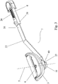
- Figs. 1 and 2 illustrate in perspective views a food peeler 1 according to a first embodiment of the present invention in the I peeler mode and in the Y peeler mode, respectively.
- This food peeler is adapted for the peel of vegetables and fruits, for example.
- the food peeler 1 comprises a handle 2 having a first end 4 and a second end 21, a holder 3 rotatably mounted on the first end 4 of the handle 2, and a cutting element 6 mounted on the holder 3.
- the handle 2 is an elongate and hollow member adapted to be held by a user of the peeler.
- the holder 3 is configured to be rotatable around a rotation axis 5 relative to the handle 2, and thus the cutting element 6 mounted on the holder 3 is also rotatable around the rotation axis 5.
- the rotation axis 5 is perpendicular to the length of the handle 2, such that the peeler 1 is transformable by the rotation of the holder 3 around the rotation axis 5, between the I peeler mode wherein the cutting element 6 is parallel to the handle 2, and the Y peeler mode wherein the cutting element 6 is perpendicular to the handle 2.
- the cutting element 6 may be symmetrically or asymmetrically mounted on the holder 3.
- the cutting element 6 is, for example, a blade with sharp cutting edges and fixedly mounted on the holder 3.
- the rotation of the holder 3 around the rotation axis 5 is actuated by an actuating assembly 7 (see Fig. 3 ).
- the actuating assembly 7 comprises a button 8 extending beyond the second end 21 of the handle 2 and a ballpoint pen mechanism which may be moved by the button 8.
- the actuating assembly 7 is configured in such a manner that when the button 8 is pressed towards the first end 4 of the handle 2 and then released, the holder 3 rotates around the rotation axis 5 by 90 degrees, with the result of the transformation of the peeler 1 from the I peeler mode into the Y peeler mode, or from the Y peeler mode into the I peeler mode.
- the detailed structure of the actuating assembly 7 will be explained herein below.
- the holder 3 may also be configured to be rotatable to any other position, without departing from the scope of the present invention.
- the holder 3 is configured to be rotatable around the rotation axis 5, by the actuating assembly 7, to at least a first position wherein the cutting element 6 is at a first angle with the handle 2, and a second position wherein the cutting element 6 is at a second angle with the handle 2.
- the first angle is 0 or 180 degrees
- the first position corresponds to the I peeler mode
- the second angle is 90 degrees
- the second position corresponds to the Y peeler mode.
- Fig. 3 shows in a perspective view the structural components of the actuating assembly 7 which is substantially accommodated in the hollow handle 2 when assembled.
- the actuating assembly 7 comprises the button 8 extending from the inside of the handle 2 beyond a second end 21 thereof and the ballpoint pen mechanism.
- a first spring 26 is provided to constantly apply an outward force to the button 8 (that is, in a direction further away from the first end 4 of the handle 2) to enable the button 8 to move outwardly after the pressure on the button 8 is released.
- the ballpoint pen mechanism comprises a linkage 22 arranged within the handle 2.
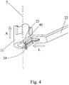
- the linkage 22 has a distal end 38 fixedly connected to an inner end 39 of the button 8 such that the linkage 22 moves longitudinally within the handle 2 together with the button 8.
- the ballpoint pen mechanism further comprises a push plunger 11 arranged at the first end 4 of the handle 2 in such a manner that the push plunger 11 is movable relative to the handle 2 in a direction perpendicular to the length of the holder 2, that is, along the rotation axis 5.
- a plunger bottom cam face 24 is formed in a bottom portion of the push plunger 11, which cooperates with the linkage cam face 23 of the linkage 22, such that the longitudinal movement (see the arrow L in Fig. 4 ) of the linkage 22 causes the axial movement (see the arrow A in Fig. 4 ) of the push plunger 11 along the rotation axis 5.
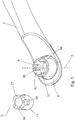
- the ballpoint pen mechanism further comprises a sleeve 9 (see Fig. 5 ) extending axially along the rotation axis 5 from the first end 4 of the holder 2.
- the sleeve 9 is shaped as a hollow cylinder with an axial throughbore 10 extending along the rotation axis 5.
- Four protrusions 12 are formed and placed evenly in a spaced apart fashion on an inner surface 13 of the sleeve 9. Each of the four protrusions 12 has a sleeve top cam face 20.
- the push plunger 11 is also shaped as a hollow cylinder with four upwardly extending portions 16 arranged evenly in a spaced apart fashion on the circumference of the top of the hollow cylinder.
- Each of the upwardly extending portions 16 has a plunger top cam face 17.
- One slot 14 between any two neighboring upwardly extending portions 16 is formed on an outer surface 15 of the push plunger 11.
- the width of the slots 14 is formed to be equal or slightly larger than the width of the respective protrusion 12 of the sleeve for slidably receiving at least part of the respective protrusion 12, such that the push plunger 11 movably engages the sleeve 9.
- the push plunger 11 is partially received in the throughbore 10 of the sleeve 9, in such a manner that the protrusions 12 of the sleeve 9 are at least partially received in the slots 14 of the push plunger 11, respectively.
- the upwardly extending portions 16 of the push plunger 11 and the protrusions 12 of the sleeve 9 are alternately arranged. In this way, the push plunger 11 is axially displaceable relative to the sleeve 9, but non-rotatable relative to the sleeve 9.
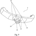
- the holder 3 is generally of a truncated Y-shape, and a cylindrical cavity 28 extending from an opened bottom of the holder 3 is formed in a lower portion of the holder 3 for accommodating the sleeve 9 and the push plunger 11.
- the push plunger 11 is accommodated in the sleeve 9
- at least a part of the sleeve 9 is accommodated in the cavity 28 of the holder 3.
- Four downwardly extending portions 37 evenly extend from a bottom surface 19 of the holder 3 (in other words, a top surface 19 of the cavity 28) in a spaced apart fashion.
- Each of the downwardly extending portions 37 has a holder bottom cam face 18 which cooperates with each of the four plunger top cam faces 17, causing the holder 3 to rotate around the rotation axis 5 when the push plunger 11 is forced upwardly to press against the holder 3.
- a hollow inner cylinder 29 extends downwardly from a center of the bottom surface 19 of the holder 3 (that is, the top surface 19 of the cavity 28) and is surrounded by the four downwardly extending portions 37. In a non-operative state, each of the four downwardly extending portions 37 is placed between two neighboring protrusions 12 of the sleeve 9 such that the holder 3 is non-rotatable relative to the sleeve 9.
- a second spring 27 is provided to constantly apply a downward force (that is, in the direction towards the sleeve 9) to the holder 3.
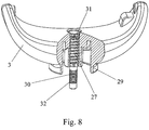
- the second spring 27 is accommodated in the hollow inner cylinder 19 and held by a holding pin 30 which is fixedly attached to the handle 2 and which has a top widened end 31 with a larger diameter than that of the second spring 27.
- the top widened end 31 of the holding pin 30 is used as a stopper of the second spring 27.
- the other end 32 of the holding pin 30 is threaded and screwed into the handle 2 (see Fig. 8 ).
- the holder 3 When the holder 3 is moved to a position where the four downwardly extending portions 37 disengage from the protrusions 12 of the sleeve 9, namely when the bottoms of the downwardly extending portions 37 are at a level higher than the tops of the protrusions 12, the holder 3 is caused to rotate around the rotation axis 5 due to the cooperating cam faces 17 and 18. When viewed from the top, the holder 3 rotates in the clockwise direction.
- the button 8 is forced by the first spring 26 to move outwardly (that is, in a direction away from the push plunger 11), causing the linkage 22 to move in the same direction with the button 8, with the linkage cam face 23 disengaging from the plunger bottom cam face 24 to allow the push plunger 11 to move downwardly.
- the second spring 27 forces the holder 3 to move downwardly too, and when the holder bottom cam faces 18 press against the sleeve top cam faces 20, the holder 3 is caused to rotate further in the clockwise direction when viewed from the top, until the highest point of each of the sleeve top cam faces 20 reaches the highest point of each of the holder bottom cam faces 18.
- the holder rotates by 90 degrees in the clockwise direction when viewed from the top every time the button 8 is pressed and then released.
- the cutting element 6 such as a blade is mounted on the holder 3 in an orientation parallel to the holder 3. Therefore, every time the button 8 is pressed and then released, the peeler 1 is switched from the Y peeler mode into the I peeler mode, or from the I peeler mode into the Y peeler mode.
- a second embodiment of the peeler of the present invention which is similar to the embodiment described above.
- the second embodiment differs from the first embodiment discussed above in the elimination of the cylindrical wall enclosing the cavity 28 in the lower portion of the holder 3.
- a locking pin 33 is partially received in a side cylinder 35 formed on a periphery of the sleeve 9 and engages with one of four locking recesses 34 formed on the bottom surface 19 of the holder 3, corresponding to the four rotary positions of the holder 3.
- the peeler 1 is working as a Y peeler and at the other two positions the peeler 1 is working as an I peeler.
- a third spring 36 is provided in the side cylinder 35 to bias the locking pin 33 towards the holder 3.
- Figs. 11 and 12 show a third embodiment of the peeler of the present invention, which differs from the first and second embodiments described above in that the button 8 is arranged at the first end 4 of the handle 2, and is adapted to be pressed in a direction along the rotation axis 5.
- the linkage 22 and the plunger bottom cam face 24 of the push plunger 11 do not exist in the third embodiment.
- the button 8 is fixedly and directly connected to the push plunger 11, such that when the button 8 is pressed, the push plunger 11 is driven to move axially along the rotation axis 5 towards the holder 3.
- the button 8 is formed integrally with the push plunger 11.
- the third embodiment of the peeler of the present invention further differs from the first and second embodiments in that the downwardly extending portions 37 having the bottom cam faces formed thereon are not formed on the bottom surface 19 of the holder 3, but instead are formed on a separate ratchet member 41 (see Fig. 12 ) which is fixedly connected to the holder 3.
- the ratchet member 41 comprises a base plate 42 and a central post 43 extending upwardly from a center of the base plate 42.
- the four downwardly extending portions 37 each having a ratchet bottom cam face 58, extend downwardly from a periphery of the base plate 42.
- the central post 43 is substantially shaped cylindrical, with a top portion 45 of the central post 43 having a square cross section, and being received in an orifice 47 formed on a bottom plate 46 of the holder 3.
- a lower portion (not shown) of the orifice 47 has a square shape corresponding to the square cross section of the top portion 45 of the central post 43, such that the ratchet member 41 is non-rotatable relative to the holder 3.
- the rotation of the ratchet member 41 around the rotation axis 5 causes the holder 3 to rotate around the rotation axis 5 together with the ratchet member 41.
- a fastening hole 53 is drilled on the central post 43, and a fastener 54 is provided to fixedly connect the central post 43 of the ratchet member 41 to the bottom plate 46 of the holder 3.
- the fastener 54 has a body 55, which extends through the orifice 47 into the fastening hole 53 and is fixedly connected to the central post 43 through the engagement between the body 55 and the fastening hole 53, for example, by threading cooperation therebetween.
- the fastener 54 further comprises an enlarged top 56 sized to be larger than the size of the orifice 47, such that the holder 3 is fixedly connected to the ratchet member 41, and moves axially along the rotation axis 5 and rotates around the rotation axis 5 together with the ratchet member 41.
- the third embodiment differs from the first and second embodiments also in that, instead of providing the protrusions 12 of the sleeve 9 being received in the slots 14 of the push plunger 11, four bulges 48 are formed and arranged evenly in a spaced apart fashion on the outer surface 15 of the push plunger 11, and are received in four troughs 49, respectively, defined by the four protrusions 12 of the sleeve 9. It can be seen in Fig. 12 that the protrusions 12 in the third embodiment are formed much wider than in the first and second embodiments in order to define the troughs 49.
- each having a plunger top cam face 17 is formed and arranged evenly in a spaced apart fashion on the circumference of the top of the push plunger 11. Therefore, at any given time, only four of the eight plunger top cam faces 17 are cooperating with the four ratchet bottom cam faces 58.
- the peeler 1 further comprises a housing member 50 fixedly connected to a top end of the sleeve 9, that is, the end of the sleeve 9 facing the holder 3.
- the housing member 50 comprises a cylindrical wall 57 and a top cover 51.
- An aperture 52 is formed on the top cover 51 for the central post 43 of the ratchet member 41 to extend through.
- the second spring 27 is coiled around the central post 43 between the top cover 51 of the housing member 50 and the base plate 42 of the ratchet member 41.
- the second spring 27 serves to constantly apply a downward force to the ratchet member 41, that is, biasing the ratchet member 41 towards the sleeve 9.
- the housing member 50 can be fixedly connected to the sleeve 9 in any manner known in the art, or formed integrally with the sleeve 9.
Landscapes
- Engineering & Computer Science (AREA)
- Food Science & Technology (AREA)
- Food-Manufacturing Devices (AREA)
- Surgical Instruments (AREA)
- Transmission Devices (AREA)
Claims (15)
- Lebensmittelschäler (1), umfassend:einen Griff (2) mit einem ersten Ende (4) und einem zweiten Ende (21), einen drehbar an dem ersten Ende (4) des Griffs (2) zur Drehung um eine Drehachse (5) angebrachten Halter (3), ein am Halter (3) angebrachtes Schneideelement (6), undeine Betätigungsanordnung (7), welche dazu eingerichtet ist, den Halter (3) so zu betätigen, dass er sich um die Drehachse (5) aus einer ersten Position, in welcher das Schneideelement (6) bezüglich des Griffs (2) in einem ersten Winkel gehalten wird, in eine zweite Position dreht, in welcher das Schneideelement (6) bezüglich des Griffs (2) in einem zweiten Winkel gehalten wird,dadurch gekennzeichnet, dassdie Betätigungsanordnung (7) eine Kugelschreibermechanik umfasst, welche am oder im Griff angeordnet und dazu eingerichtet ist, die Drehung des Halters (3) in einer Ebene parallel zu einer Länge des Griffs (2) und um die Drehachse (5) auszulösen, und einen mit der Kugelschreibermechanik verbundenen Druckknopf (8), um die Kugelschreibermechanik axial entlang der Drehachse (5) zu bewegen; und dadurch, dass die axiale Bewegung die Drehung des Halters (3) um die Drehachse (5) bewirkt.
- Lebensmittelschäler (1) gemäß Anspruch 1, wobei die Drehachse (5) vorzugsweise senkrecht zum Griff (2) steht, und das Schneideelement (6) dazu eingerichtet ist, parallel zum Griff (2) zu stehen, wenn sich der Halter (3) in der ersten Position befindet, und senkrecht zum Griff (2) zu stehen, wenn sich der Halter (3) in der zweiten Position befindet.
- Lebensmittelschäler (1) gemäß einem der Ansprüche 1 oder 2, wobei die Kugelschreibermechanik dazu eingerichtet ist, dass sich der Halter (3) jedes Mal um 90 Grad um die Drehachse (5) dreht, wenn der Druckknopf zum Bewegen der Kugelschreibermechanik gedrückt wird.
- Lebensmittelschäler (1) gemäß Anspruch 3, wobei die Kugelschreibermechanik umfasst: eine Hülse (9), welche am ersten Ende (4) des Griffs (2) befestigt ist und eine sich entlang der Drehachse (5) erstreckende, axiale Durchgangsbohrung (10) aufweist, und einen Druckkolben (11), welcher wenigstens zum Teil in der Durchgangsbohrung (10) der Hülse (9) aufgenommenen und zum beweglichen Eingriff mit der Hülse (9) eingerichtet ist, wobei der Halter (3) zur Drehung um die Drehachse (5) relativ zum Griff (2) veranlasst wird, wenn der Druckkolben (11) zu einer axialen Bewegung entlang der Drehachse (5) in Richtung des Halters (3) veranlasst wird.
- Lebensmittelschäler (1) gemäß Anspruch 4, wobei die Hülse (9) eine Vielzahl von Vorsprüngen (12) umfasst, welche auf einer Innenseite (13) der Durchgangsbohrung (10) ausgebildet und gleichmäßig voneinander beabstandet angeordnet sind, und wobei der Druckkolben (11) eine Vielzahl von Schlitzen (14) umfasst, welche auf einer Außenseite (15) des Druckkolbens (11) ausgebildet und gleichmäßig voneinander beabstandet angeordnet sind, um die Vorsprünge (12) der Hülse (9) wenigstens zum Teil entsprechend aufzunehmen.
- Lebensmittelschäler (1) gemäß Anspruch 5, wobei der Druckkolben (11) eine Vielzahl sich nach oben erstreckender Abschnitte (16) umfasst, welche auf seiner Außenseite (15) gleichmäßig beabstandet angeordnet sind, wobei jeder der sich nach oben erstreckenden Abschnitte (16) eine obere Kolben-Steuerfläche (17) aufweist; und wobei der Halter (3) eine Vielzahl sich von seiner Unterseite (19) aus nach unten erstreckender Abschnitte (37) umfasst, wobei jeder der sich nach unten erstreckenden Abschnitte (37) eine untere Halter-Steuerfläche (18) aufweist; wobei die oberen Kolben-Steuerflächen (17) mit den unteren Halter-Steuerflächen (18) zusammenwirken, wenn der Druckkolben (11) gegen den Halter (3) gedrückt wird, wodurch der Halter (3) um die Drehachse (5) gedreht wird.
- Lebensmittelschäler (1) gemäß Anspruch 6, wobei zur konstanten Ausübung einer Kraft auf den Halter (3) eine zweite Feder (27) vorgesehen ist, so dass der Halter (3) bestrebt ist, sich in Richtung auf die Hülse (9) zu bewegen, und wobei jeder der Vorsprünge (12) der Hülse (9) eine obere Hülsen-Steuerfläche (20) aufweist, die mit den unteren Halter-Steuerflächen (18) zusammenwirkt, so dass sich der Halter (3) weiter um die Drehachse dreht (5), wenn der Halter (3) mittels der zweiten Feder (27) gegen die Hülse (9) gedrückt wird.
- Lebensmittelschäler (1) gemäß einem der Ansprüche 4 bis 7, wobei der Druckknopf (8) am zweiten Ende (21) des Griffs (2) vorgesehen ist, und wobei die Betätigungsanordnung (7) ferner einen Verbinder (22) umfasst mit einem distalen Ende (38), welches fest mit dem Druckknopf (8) verbunden ist, und einem proximalen Ende (40), welches als Verbinder-Steuerfläche (23) ausgebildet ist, wobei die Verbinder-Steuerfläche (23) mit einer an einem Boden des Druckkolbens (11) ausgebildeten, unteren Kolben-Steuerfläche (24) zusammenwirkt, um die Axialbewegung des Druckkolbens (11) entlang der Drehachse (5) in Richtung des Halters (3) zu treiben, wenn der Druckknopf (8) gegen den Druckkolben (11) gedrückt wird, wobei eine erste, mit dem Druckknopf (8) verbundene Feder (26) vorgesehen ist, um konstant eine Kraft auf den Druckknopf (8) auszuüben, so dass der Druckknopf (8) bestrebt ist, sich vom Druckkolben (11) wegzubewegen.
- Lebensmittelschäler (1) gemäß einem der Ansprüche 4 bis 8, wobei wenigstens ein Verriegelungsstift (33) an der Hülse (9) angebracht ist und mit einer von mehreren, an einer Unterseite (19) des Halters (3) ausgebildeten Verriegelungsausnehmungen (34) in Eingriff steht, um den Halter (3) in einer entsprechenden der ersten Position oder zweiten Position zu verriegeln, wobei der Verriegelungsstift (33) teilweise in einem an einer Seitenfläche der Hülse (9) ausgebildeten Seitenzylinder (35) aufgenommen und mittels einer dritten Feder (36) in Richtung des Halters (3) vorgespannt ist.
- Lebensmittelschäler (1) gemäß Anspruch 4, wobei die Hülse (9) eine Vielzahl von Vorsprüngen (12) umfasst, welche mit einer Vielzahl von auf der Innenseite (13) der Durchgangsbohrung (10) ausgebildeten und voneinander beabstandet angeordneten Vertiefungen (49) abwechseln, und wobei der Druckkolben (11) eine Vielzahl von auf der Außenseite (15) des Druckkolbens (11) ausgebildeten und gleichmäßig voneinander beabstandet angeordneten Vorwölbungen (48) umfasst, wobei die Vorwölbungen (48) in den entsprechenden Vertiefungen (49) der Hülse (9) aufgenommen sind.
- Lebensmittelschäler (1) gemäß Anspruch 10, wobei der Druckkolben (11) eine Vielzahl sich nach oben erstreckender Abschnitte (16) umfasst, welche auf seiner Außenseite (15) gleichmäßig voneinander beabstandet angeordnet sind, wobei jeder der sich nach oben erstreckenden Abschnitte (16) eine obere Kolben-Steuerfläche (17) aufweist; und wobei der Halter (3) fest mit einem Ratschenelement (41) verbunden ist, welches eine Grundplatte (42) und mehrere, sich in Umfangsrichtung von der Grundplatte (42) aus nach unten erstreckende Abschnitte (37) umfasst, wobei jeder der sich nach unten erstreckenden Abschnitte (37) eine untere Ratschen-Steuerfläche (58) aufweist; wobei die oberen Kolben-Steuerflächen (17) mit den unteren Ratschen-Steuerflächen (58) zusammenwirken, wenn der Kolben (11) gegen das Ratschenelement (41) gedrückt wird, wodurch das Ratschenelement (41) um die Drehachse (5) gedreht wird, wodurch wiederum der Halter zur Drehung um die Drehachse (5) angetrieben wird.
- Lebensmittelschäler (1) gemäß Anspruch 11, wobei zur konstanten Ausübung einer Kraft auf das Ratschenelement (41) eine zweite Feder (27) vorgesehen ist, so dass das Ratschenelement (41) zusammen mit dem Halter (3) bestrebt ist, sich in Richtung der Hülse (9) zu bewegen.
- Lebensmittelschäler (1) gemäß Anspruch 12, wobei jeder der Vorsprünge (12) der Hülse (9) eine mit den unteren Ratschen-Steuerflächen (58) zusammenwirkende, obere Hülsen-Steuerfläche (20) aufweist, so dass eine weitere Drehung des Ratschenelements (41) und des Halters (3) um die Drehachse (5) bewirkt wird, wenn das Ratschenelement (41) mittels der zweiten Feder (27) gegen die Hülse (9) gedrückt wird.
- Lebensmittelschäler (1) gemäß Anspruch 13, wobei der Druckknopf (8) am ersten Ende (4) des Griffs (2) vorgesehen und fest mit dem Druckkolben (11) verbunden ist, um im gedrückten Zustand die axiale Bewegung des Druckkolbens (11) entlang der Drehachse (5) in Richtung auf das Ratschenelement (41) zu bewirken.
- Lebensmittelschäler (1) gemäß Anspruch 14, wobei das Ratschenelement (41) ferner einen sich von der Grundplatte (42) nach oben erstreckenden und mit dem Halter (3) fest verbundenen, zentralen Stab (43) umfasst, und wobei der Lebensmittelschäler (1) weiterhin ein fest mit der Hülse (9) verbundenes Gehäuseelement (50) umfasst, wobei das Gehäuseelement (50) eine obere Abdeckung (51) aufweist mit einer darin ausgebildeten Öffnung (52) als Durchgang für den zentralen Stab (43) des Ratschenelements (41), wobei die zweite Feder (27) mittels des zentralen Stabs (43) zwischen der oberen Abdeckung (51) des Gehäuseelements (50) und der Grundplatte (42) des Ratschenelements (41) gehalten wird, um auf das Ratschenelement (41) konstant eine Kraft auszuüben, so dass das Ratschenelement (41) zusammen mit dem Halter (3) bestrebt ist, sich in Richtung der Hülse (9) zu bewegen.
Applications Claiming Priority (1)
| Application Number | Priority Date | Filing Date | Title |
|---|---|---|---|
| US201562105810P | 2015-01-21 | 2015-01-21 |
Publications (2)
| Publication Number | Publication Date |
|---|---|
| EP3047764A1 EP3047764A1 (de) | 2016-07-27 |
| EP3047764B1 true EP3047764B1 (de) | 2018-08-22 |
Family
ID=55177877
Family Applications (1)
| Application Number | Title | Priority Date | Filing Date |
|---|---|---|---|
| EP16152140.6A Active EP3047764B1 (de) | 2015-01-21 | 2016-01-20 | Lebensmittelschäler |
Country Status (3)
| Country | Link |
|---|---|
| US (1) | US10405685B2 (de) |
| EP (1) | EP3047764B1 (de) |
| CN (1) | CN105795873B (de) |
Families Citing this family (15)
| Publication number | Priority date | Publication date | Assignee | Title |
|---|---|---|---|---|
| US10405685B2 (en) * | 2015-01-21 | 2019-09-10 | King's Flair Development Ltd. | Food peeler |
| US9717174B2 (en) * | 2015-06-23 | 2017-08-01 | Hank Hung Kung Chou | Ergonomic rotational handle for a garden tool |
| WO2018007845A1 (en) * | 2016-07-08 | 2018-01-11 | Bic Violex S.A. | Reconfigurable shaving razors with articulating head |
| CN107232955B (zh) * | 2016-11-10 | 2023-02-28 | 深圳市米拉宝家庭用品有限公司 | 多用削皮器 |
| US10828026B2 (en) * | 2017-08-08 | 2020-11-10 | Covidien Lp | Tiltable anvil assembly |
| US10889013B2 (en) * | 2019-01-03 | 2021-01-12 | Slice, Inc. | Cutting device |
| USD1047650S1 (en) | 2022-08-30 | 2024-10-22 | Instant Brands Holdings Inc. | Utility knife |
| USD1046588S1 (en) | 2022-08-30 | 2024-10-15 | Instant Brands Holdings Inc. | Utility knife |
| USD1048847S1 (en) | 2022-08-30 | 2024-10-29 | Instant Brands Holdings Inc. | Utility knife |
| USD1032316S1 (en) | 2022-11-23 | 2024-06-25 | Instant Brands Holdings Inc. | Scissors |
| USD1039936S1 (en) | 2022-11-23 | 2024-08-27 | Instant Brands Holdings Inc. | Cutting tool |
| USD1041283S1 (en) | 2022-11-23 | 2024-09-10 | Instant Brands Holdings Inc. | Utility knife |
| USD1030433S1 (en) | 2022-11-23 | 2024-06-11 | Instant Brands Holdings Inc. | Scissors |
| USD1041284S1 (en) | 2022-11-23 | 2024-09-10 | Instant Brands Holdings Inc. | Utility knife |
| USD1068412S1 (en) * | 2023-02-28 | 2025-04-01 | Dongxia Feng | Peeler |
Family Cites Families (26)
| Publication number | Priority date | Publication date | Assignee | Title |
|---|---|---|---|---|
| US2121000A (en) * | 1932-01-27 | 1938-06-21 | John W Anderson | Safety razor |
| US2031191A (en) * | 1934-09-13 | 1936-02-18 | Swedeland Adolf | Paring knife |
| US3956825A (en) * | 1975-02-19 | 1976-05-18 | Raymond Lee Organization | Potato and vegetable peelers |
| US3942249A (en) * | 1975-04-02 | 1976-03-09 | Poehlmann Paul W | Knife |
| US4083103A (en) * | 1975-09-19 | 1978-04-11 | Estandian Ramon D | Adjustable safety razor |
| US4233737A (en) * | 1979-04-13 | 1980-11-18 | Poehlmann Paul W | Knife with removable blade |
| US5093991A (en) * | 1990-11-05 | 1992-03-10 | Hendrickson Terrance M | Adjustable razor |
| US5467498A (en) * | 1993-10-13 | 1995-11-21 | Keegan; Joseph P. | Self-sharpening scraping tool |
| JP2000175808A (ja) * | 1998-12-11 | 2000-06-27 | Choichiro Sugawa | 皮剥具 |
| US6619194B1 (en) * | 2002-10-14 | 2003-09-16 | Huo Feng Hsia Kuan | Omni-bearing peeler |
| ATE383799T1 (de) * | 2002-11-06 | 2008-02-15 | Michael Haberstroh | Sparschäler |
| US7415769B2 (en) * | 2003-08-08 | 2008-08-26 | Rubbermaid Incorporated | Vegetable peeler with pivoting head |
| US7185436B2 (en) * | 2004-03-30 | 2007-03-06 | Kyocera Tycom Corporation | Multi-position peeler apparatus |
| US20050278957A1 (en) * | 2004-06-16 | 2005-12-22 | Mccullough David K | Cheese cutting apparatus |
| DE202005016925U1 (de) * | 2005-01-22 | 2006-01-19 | Proma Gmbh Projektmanagement | Schälmesser |
| US20070227013A1 (en) * | 2006-03-30 | 2007-10-04 | Progressive International Corporation | Convertible peeler |
| DE202010018286U1 (de) * | 2010-04-26 | 2015-05-15 | Fackelmann Gmbh + Co Kg | Schäl-Messer |
| DE202011103365U1 (de) * | 2011-07-16 | 2011-08-31 | Carsten Rauh | Schälmesser für Kartoffeln, Gemüse und Obst |
| US20130047444A1 (en) * | 2011-08-22 | 2013-02-28 | Thomas Ientile | Geared melon peeler |
| US9289088B2 (en) * | 2013-09-13 | 2016-03-22 | Mikhael Vitenson | Peeler and slicer |
| US9446530B2 (en) * | 2014-02-28 | 2016-09-20 | King's Flair Development Ltd. | Mandolin slicer |
| US9516975B2 (en) * | 2014-04-18 | 2016-12-13 | King's Flair Development Ltd. | Condiment mill |
| US9296115B2 (en) * | 2014-04-18 | 2016-03-29 | King's Flair Development Ltd. | Cheese slicer |
| US10405685B2 (en) * | 2015-01-21 | 2019-09-10 | King's Flair Development Ltd. | Food peeler |
| CH711357A2 (de) * | 2015-07-28 | 2017-01-31 | Moha Moderne Haushaltwaren Ag | Sparschäler. |
| FR3039760B1 (fr) * | 2015-08-05 | 2017-08-25 | Karis | Ustensile a main de cuisine |
-
2016
- 2016-01-20 US US15/001,782 patent/US10405685B2/en active Active
- 2016-01-20 CN CN201610038401.5A patent/CN105795873B/zh active Active
- 2016-01-20 EP EP16152140.6A patent/EP3047764B1/de active Active
Non-Patent Citations (1)
| Title |
|---|
| None * |
Also Published As
| Publication number | Publication date |
|---|---|
| US10405685B2 (en) | 2019-09-10 |
| US20160206129A1 (en) | 2016-07-21 |
| CN105795873A (zh) | 2016-07-27 |
| EP3047764A1 (de) | 2016-07-27 |
| CN105795873B (zh) | 2018-12-04 |
Similar Documents
| Publication | Publication Date | Title |
|---|---|---|
| EP3047764B1 (de) | Lebensmittelschäler | |
| US7185436B2 (en) | Multi-position peeler apparatus | |
| EP2913164B1 (de) | Gemüsehobel | |
| US7886444B2 (en) | Foldable knife having switch element | |
| US6619194B1 (en) | Omni-bearing peeler | |
| US9079323B2 (en) | Slicing device | |
| EP2632666B1 (de) | Apfelschneider | |
| US20100269352A1 (en) | Y peeler | |
| US7631429B2 (en) | Handheld peeler with removable multi-blade cartridge | |
| EP3040170B1 (de) | Messerkombinationsvorrichtung für lebensmittel | |
| US9186806B2 (en) | Handheld food slicer | |
| US20120042525A1 (en) | Cutting Device for Food Products and Method of Using the Same | |
| EP1576916B1 (de) | Hacker für Lebensmittel | |
| US10035280B2 (en) | Mandolin slicer | |
| US20130020749A1 (en) | Device for holding and preparing a food product | |
| HK1227268B (en) | Food peeler | |
| US10104998B2 (en) | Peeler | |
| US7263776B1 (en) | Fruit and vegetable seed removing device | |
| HK1227268A1 (en) | Food peeler | |
| EP2721981B1 (de) | Schneidevorrichtung für Obst und Gemüse | |
| US20230414028A1 (en) | Fruit slitting device | |
| EP3456889B1 (de) | Drehmechanismus und wasserhahn mit diesem mechanismus | |
| KR20130080378A (ko) | 여러개의 모드를 갖는 다용도 슬라이서 | |
| US4141541A (en) | Hand utensil for holding a citrus fruit | |
| US20140208963A1 (en) | Slicer |
Legal Events
| Date | Code | Title | Description |
|---|---|---|---|
| PUAI | Public reference made under article 153(3) epc to a published international application that has entered the european phase |
Free format text: ORIGINAL CODE: 0009012 |
|
| AK | Designated contracting states |
Kind code of ref document: A1 Designated state(s): AL AT BE BG CH CY CZ DE DK EE ES FI FR GB GR HR HU IE IS IT LI LT LU LV MC MK MT NL NO PL PT RO RS SE SI SK SM TR |
|
| AX | Request for extension of the european patent |
Extension state: BA ME |
|
| STAA | Information on the status of an ep patent application or granted ep patent |
Free format text: STATUS: REQUEST FOR EXAMINATION WAS MADE |
|
| 17P | Request for examination filed |
Effective date: 20170125 |
|
| RBV | Designated contracting states (corrected) |
Designated state(s): AL AT BE BG CH CY CZ DE DK EE ES FI FR GB GR HR HU IE IS IT LI LT LU LV MC MK MT NL NO PL PT RO RS SE SI SK SM TR |
|
| REG | Reference to a national code |
Ref country code: HK Ref legal event code: DE Ref document number: 1227268 Country of ref document: HK |
|
| GRAP | Despatch of communication of intention to grant a patent |
Free format text: ORIGINAL CODE: EPIDOSNIGR1 |
|
| STAA | Information on the status of an ep patent application or granted ep patent |
Free format text: STATUS: GRANT OF PATENT IS INTENDED |
|
| INTG | Intention to grant announced |
Effective date: 20180320 |
|
| GRAS | Grant fee paid |
Free format text: ORIGINAL CODE: EPIDOSNIGR3 |
|
| GRAA | (expected) grant |
Free format text: ORIGINAL CODE: 0009210 |
|
| STAA | Information on the status of an ep patent application or granted ep patent |
Free format text: STATUS: THE PATENT HAS BEEN GRANTED |
|
| AK | Designated contracting states |
Kind code of ref document: B1 Designated state(s): AL AT BE BG CH CY CZ DE DK EE ES FI FR GB GR HR HU IE IS IT LI LT LU LV MC MK MT NL NO PL PT RO RS SE SI SK SM TR |
|
| REG | Reference to a national code |
Ref country code: GB Ref legal event code: FG4D |
|
| REG | Reference to a national code |
Ref country code: CH Ref legal event code: EP |
|
| REG | Reference to a national code |
Ref country code: AT Ref legal event code: REF Ref document number: 1031467 Country of ref document: AT Kind code of ref document: T Effective date: 20180915 |
|
| REG | Reference to a national code |
Ref country code: IE Ref legal event code: FG4D |
|
| REG | Reference to a national code |
Ref country code: DE Ref legal event code: R096 Ref document number: 602016004853 Country of ref document: DE |
|
| REG | Reference to a national code |
Ref country code: NL Ref legal event code: MP Effective date: 20180822 |
|
| REG | Reference to a national code |
Ref country code: LT Ref legal event code: MG4D |
|
| PG25 | Lapsed in a contracting state [announced via postgrant information from national office to epo] |
Ref country code: NL Free format text: LAPSE BECAUSE OF FAILURE TO SUBMIT A TRANSLATION OF THE DESCRIPTION OR TO PAY THE FEE WITHIN THE PRESCRIBED TIME-LIMIT Effective date: 20180822 Ref country code: LT Free format text: LAPSE BECAUSE OF FAILURE TO SUBMIT A TRANSLATION OF THE DESCRIPTION OR TO PAY THE FEE WITHIN THE PRESCRIBED TIME-LIMIT Effective date: 20180822 Ref country code: BG Free format text: LAPSE BECAUSE OF FAILURE TO SUBMIT A TRANSLATION OF THE DESCRIPTION OR TO PAY THE FEE WITHIN THE PRESCRIBED TIME-LIMIT Effective date: 20181122 Ref country code: GR Free format text: LAPSE BECAUSE OF FAILURE TO SUBMIT A TRANSLATION OF THE DESCRIPTION OR TO PAY THE FEE WITHIN THE PRESCRIBED TIME-LIMIT Effective date: 20181123 Ref country code: NO Free format text: LAPSE BECAUSE OF FAILURE TO SUBMIT A TRANSLATION OF THE DESCRIPTION OR TO PAY THE FEE WITHIN THE PRESCRIBED TIME-LIMIT Effective date: 20181122 Ref country code: SE Free format text: LAPSE BECAUSE OF FAILURE TO SUBMIT A TRANSLATION OF THE DESCRIPTION OR TO PAY THE FEE WITHIN THE PRESCRIBED TIME-LIMIT Effective date: 20180822 Ref country code: IS Free format text: LAPSE BECAUSE OF FAILURE TO SUBMIT A TRANSLATION OF THE DESCRIPTION OR TO PAY THE FEE WITHIN THE PRESCRIBED TIME-LIMIT Effective date: 20181222 Ref country code: RS Free format text: LAPSE BECAUSE OF FAILURE TO SUBMIT A TRANSLATION OF THE DESCRIPTION OR TO PAY THE FEE WITHIN THE PRESCRIBED TIME-LIMIT Effective date: 20180822 Ref country code: FI Free format text: LAPSE BECAUSE OF FAILURE TO SUBMIT A TRANSLATION OF THE DESCRIPTION OR TO PAY THE FEE WITHIN THE PRESCRIBED TIME-LIMIT Effective date: 20180822 |
|
| REG | Reference to a national code |
Ref country code: AT Ref legal event code: MK05 Ref document number: 1031467 Country of ref document: AT Kind code of ref document: T Effective date: 20180822 |
|
| PG25 | Lapsed in a contracting state [announced via postgrant information from national office to epo] |
Ref country code: HR Free format text: LAPSE BECAUSE OF FAILURE TO SUBMIT A TRANSLATION OF THE DESCRIPTION OR TO PAY THE FEE WITHIN THE PRESCRIBED TIME-LIMIT Effective date: 20180822 Ref country code: AL Free format text: LAPSE BECAUSE OF FAILURE TO SUBMIT A TRANSLATION OF THE DESCRIPTION OR TO PAY THE FEE WITHIN THE PRESCRIBED TIME-LIMIT Effective date: 20180822 Ref country code: LV Free format text: LAPSE BECAUSE OF FAILURE TO SUBMIT A TRANSLATION OF THE DESCRIPTION OR TO PAY THE FEE WITHIN THE PRESCRIBED TIME-LIMIT Effective date: 20180822 |
|
| PG25 | Lapsed in a contracting state [announced via postgrant information from national office to epo] |
Ref country code: ES Free format text: LAPSE BECAUSE OF FAILURE TO SUBMIT A TRANSLATION OF THE DESCRIPTION OR TO PAY THE FEE WITHIN THE PRESCRIBED TIME-LIMIT Effective date: 20180822 Ref country code: AT Free format text: LAPSE BECAUSE OF FAILURE TO SUBMIT A TRANSLATION OF THE DESCRIPTION OR TO PAY THE FEE WITHIN THE PRESCRIBED TIME-LIMIT Effective date: 20180822 Ref country code: IT Free format text: LAPSE BECAUSE OF FAILURE TO SUBMIT A TRANSLATION OF THE DESCRIPTION OR TO PAY THE FEE WITHIN THE PRESCRIBED TIME-LIMIT Effective date: 20180822 Ref country code: RO Free format text: LAPSE BECAUSE OF FAILURE TO SUBMIT A TRANSLATION OF THE DESCRIPTION OR TO PAY THE FEE WITHIN THE PRESCRIBED TIME-LIMIT Effective date: 20180822 Ref country code: EE Free format text: LAPSE BECAUSE OF FAILURE TO SUBMIT A TRANSLATION OF THE DESCRIPTION OR TO PAY THE FEE WITHIN THE PRESCRIBED TIME-LIMIT Effective date: 20180822 Ref country code: CZ Free format text: LAPSE BECAUSE OF FAILURE TO SUBMIT A TRANSLATION OF THE DESCRIPTION OR TO PAY THE FEE WITHIN THE PRESCRIBED TIME-LIMIT Effective date: 20180822 Ref country code: PL Free format text: LAPSE BECAUSE OF FAILURE TO SUBMIT A TRANSLATION OF THE DESCRIPTION OR TO PAY THE FEE WITHIN THE PRESCRIBED TIME-LIMIT Effective date: 20180822 |
|
| REG | Reference to a national code |
Ref country code: DE Ref legal event code: R097 Ref document number: 602016004853 Country of ref document: DE |
|
| PG25 | Lapsed in a contracting state [announced via postgrant information from national office to epo] |
Ref country code: DK Free format text: LAPSE BECAUSE OF FAILURE TO SUBMIT A TRANSLATION OF THE DESCRIPTION OR TO PAY THE FEE WITHIN THE PRESCRIBED TIME-LIMIT Effective date: 20180822 Ref country code: SK Free format text: LAPSE BECAUSE OF FAILURE TO SUBMIT A TRANSLATION OF THE DESCRIPTION OR TO PAY THE FEE WITHIN THE PRESCRIBED TIME-LIMIT Effective date: 20180822 Ref country code: SM Free format text: LAPSE BECAUSE OF FAILURE TO SUBMIT A TRANSLATION OF THE DESCRIPTION OR TO PAY THE FEE WITHIN THE PRESCRIBED TIME-LIMIT Effective date: 20180822 |
|
| PLBE | No opposition filed within time limit |
Free format text: ORIGINAL CODE: 0009261 |
|
| STAA | Information on the status of an ep patent application or granted ep patent |
Free format text: STATUS: NO OPPOSITION FILED WITHIN TIME LIMIT |
|
| 26N | No opposition filed |
Effective date: 20190523 |
|
| PG25 | Lapsed in a contracting state [announced via postgrant information from national office to epo] |
Ref country code: MC Free format text: LAPSE BECAUSE OF FAILURE TO SUBMIT A TRANSLATION OF THE DESCRIPTION OR TO PAY THE FEE WITHIN THE PRESCRIBED TIME-LIMIT Effective date: 20180822 Ref country code: SI Free format text: LAPSE BECAUSE OF FAILURE TO SUBMIT A TRANSLATION OF THE DESCRIPTION OR TO PAY THE FEE WITHIN THE PRESCRIBED TIME-LIMIT Effective date: 20180822 |
|
| REG | Reference to a national code |
Ref country code: CH Ref legal event code: PL |
|
| PG25 | Lapsed in a contracting state [announced via postgrant information from national office to epo] |
Ref country code: LU Free format text: LAPSE BECAUSE OF NON-PAYMENT OF DUE FEES Effective date: 20190120 |
|
| REG | Reference to a national code |
Ref country code: BE Ref legal event code: MM Effective date: 20190131 |
|
| REG | Reference to a national code |
Ref country code: IE Ref legal event code: MM4A |
|
| PG25 | Lapsed in a contracting state [announced via postgrant information from national office to epo] |
Ref country code: FR Free format text: LAPSE BECAUSE OF NON-PAYMENT OF DUE FEES Effective date: 20190131 |
|
| PG25 | Lapsed in a contracting state [announced via postgrant information from national office to epo] |
Ref country code: BE Free format text: LAPSE BECAUSE OF NON-PAYMENT OF DUE FEES Effective date: 20190131 |
|
| PG25 | Lapsed in a contracting state [announced via postgrant information from national office to epo] |
Ref country code: CH Free format text: LAPSE BECAUSE OF NON-PAYMENT OF DUE FEES Effective date: 20190131 Ref country code: LI Free format text: LAPSE BECAUSE OF NON-PAYMENT OF DUE FEES Effective date: 20190131 |
|
| PG25 | Lapsed in a contracting state [announced via postgrant information from national office to epo] |
Ref country code: IE Free format text: LAPSE BECAUSE OF NON-PAYMENT OF DUE FEES Effective date: 20190120 |
|
| PG25 | Lapsed in a contracting state [announced via postgrant information from national office to epo] |
Ref country code: TR Free format text: LAPSE BECAUSE OF FAILURE TO SUBMIT A TRANSLATION OF THE DESCRIPTION OR TO PAY THE FEE WITHIN THE PRESCRIBED TIME-LIMIT Effective date: 20180822 |
|
| PG25 | Lapsed in a contracting state [announced via postgrant information from national office to epo] |
Ref country code: MT Free format text: LAPSE BECAUSE OF NON-PAYMENT OF DUE FEES Effective date: 20190120 Ref country code: PT Free format text: LAPSE BECAUSE OF FAILURE TO SUBMIT A TRANSLATION OF THE DESCRIPTION OR TO PAY THE FEE WITHIN THE PRESCRIBED TIME-LIMIT Effective date: 20181222 |
|
| PG25 | Lapsed in a contracting state [announced via postgrant information from national office to epo] |
Ref country code: CY Free format text: LAPSE BECAUSE OF FAILURE TO SUBMIT A TRANSLATION OF THE DESCRIPTION OR TO PAY THE FEE WITHIN THE PRESCRIBED TIME-LIMIT Effective date: 20180822 |
|
| PG25 | Lapsed in a contracting state [announced via postgrant information from national office to epo] |
Ref country code: HU Free format text: LAPSE BECAUSE OF FAILURE TO SUBMIT A TRANSLATION OF THE DESCRIPTION OR TO PAY THE FEE WITHIN THE PRESCRIBED TIME-LIMIT; INVALID AB INITIO Effective date: 20160120 |
|
| PG25 | Lapsed in a contracting state [announced via postgrant information from national office to epo] |
Ref country code: MK Free format text: LAPSE BECAUSE OF FAILURE TO SUBMIT A TRANSLATION OF THE DESCRIPTION OR TO PAY THE FEE WITHIN THE PRESCRIBED TIME-LIMIT Effective date: 20180822 |
|
| P01 | Opt-out of the competence of the unified patent court (upc) registered |
Effective date: 20230529 |
|
| P02 | Opt-out of the competence of the unified patent court (upc) changed |
Effective date: 20230601 |
|
| PGFP | Annual fee paid to national office [announced via postgrant information from national office to epo] |
Ref country code: GB Payment date: 20260121 Year of fee payment: 11 |
|
| PGFP | Annual fee paid to national office [announced via postgrant information from national office to epo] |
Ref country code: DE Payment date: 20260120 Year of fee payment: 11 |