EP3047341B1 - System for the computer-assisted creation of rules for monitoring and/or diagnosing a technical plant - Google Patents
System for the computer-assisted creation of rules for monitoring and/or diagnosing a technical plant Download PDFInfo
- Publication number
- EP3047341B1 EP3047341B1 EP14793564.7A EP14793564A EP3047341B1 EP 3047341 B1 EP3047341 B1 EP 3047341B1 EP 14793564 A EP14793564 A EP 14793564A EP 3047341 B1 EP3047341 B1 EP 3047341B1
- Authority
- EP
- European Patent Office
- Prior art keywords
- ontology
- rules
- rule
- plant
- concepts
- Prior art date
- Legal status (The legal status is an assumption and is not a legal conclusion. Google has not performed a legal analysis and makes no representation as to the accuracy of the status listed.)
- Not-in-force
Links
- 238000012544 monitoring process Methods 0.000 title claims description 31
- 238000000034 method Methods 0.000 claims description 45
- 230000008569 process Effects 0.000 claims description 33
- 238000012795 verification Methods 0.000 claims description 10
- 230000009466 transformation Effects 0.000 claims description 5
- 238000004590 computer program Methods 0.000 claims description 2
- 239000000463 material Substances 0.000 description 29
- 230000000694 effects Effects 0.000 description 24
- 238000009434 installation Methods 0.000 description 11
- 238000003745 diagnosis Methods 0.000 description 10
- 238000012545 processing Methods 0.000 description 8
- 238000004519 manufacturing process Methods 0.000 description 7
- 230000009471 action Effects 0.000 description 5
- 238000006243 chemical reaction Methods 0.000 description 5
- 238000005265 energy consumption Methods 0.000 description 5
- 230000008901 benefit Effects 0.000 description 4
- 230000008094 contradictory effect Effects 0.000 description 3
- 238000013461 design Methods 0.000 description 3
- 238000010586 diagram Methods 0.000 description 3
- 238000013519 translation Methods 0.000 description 3
- 230000008859 change Effects 0.000 description 2
- 239000010432 diamond Substances 0.000 description 2
- 239000012634 fragment Substances 0.000 description 2
- 238000012423 maintenance Methods 0.000 description 2
- 230000007246 mechanism Effects 0.000 description 2
- 239000008188 pellet Substances 0.000 description 2
- ZXNNHZMSXGXEIJ-UHFFFAOYSA-N Actein Natural products CC1CC2(OC(O)C3(C)OC23)OC4C(O)C5(C)C6CCC7C(C)(C)C(CCC78CC68CC(OC(=O)C)C5(C)C14)OC9OCC(O)C(O)C9O ZXNNHZMSXGXEIJ-UHFFFAOYSA-N 0.000 description 1
- 241001463014 Chazara briseis Species 0.000 description 1
- NEWMWGLPJQHSSQ-PMICRNDLSA-N actein Chemical compound O([C@H]1CC[C@@]23[C@H](C1(C)C)CC[C@H]1[C@]4(C)C[C@@H]5O[C@]6([C@@H]7O[C@]7(C)C(O)O6)C[C@H]([C@@H]5[C@@]4(C)[C@H](OC(C)=O)C[C@]12C3)C)[C@@H]1OC[C@@H](O)[C@H](O)[C@H]1O NEWMWGLPJQHSSQ-PMICRNDLSA-N 0.000 description 1
- 230000006978 adaptation Effects 0.000 description 1
- 238000004422 calculation algorithm Methods 0.000 description 1
- 230000000295 complement effect Effects 0.000 description 1
- 150000001875 compounds Chemical class 0.000 description 1
- 230000001419 dependent effect Effects 0.000 description 1
- 238000009795 derivation Methods 0.000 description 1
- 238000011161 development Methods 0.000 description 1
- 230000018109 developmental process Effects 0.000 description 1
- 238000005516 engineering process Methods 0.000 description 1
- 230000004927 fusion Effects 0.000 description 1
- 230000007257 malfunction Effects 0.000 description 1
- 238000013507 mapping Methods 0.000 description 1
- 239000007787 solid Substances 0.000 description 1
- 230000001131 transforming effect Effects 0.000 description 1
- 238000012800 visualization Methods 0.000 description 1
Images


Classifications
-
- G—PHYSICS
- G06—COMPUTING; CALCULATING OR COUNTING
- G06N—COMPUTING ARRANGEMENTS BASED ON SPECIFIC COMPUTATIONAL MODELS
- G06N5/00—Computing arrangements using knowledge-based models
- G06N5/02—Knowledge representation; Symbolic representation
- G06N5/022—Knowledge engineering; Knowledge acquisition
-
- G—PHYSICS
- G05—CONTROLLING; REGULATING
- G05B—CONTROL OR REGULATING SYSTEMS IN GENERAL; FUNCTIONAL ELEMENTS OF SUCH SYSTEMS; MONITORING OR TESTING ARRANGEMENTS FOR SUCH SYSTEMS OR ELEMENTS
- G05B19/00—Programme-control systems
- G05B19/02—Programme-control systems electric
- G05B19/04—Programme control other than numerical control, i.e. in sequence controllers or logic controllers
- G05B19/042—Programme control other than numerical control, i.e. in sequence controllers or logic controllers using digital processors
- G05B19/0428—Safety, monitoring
-
- G—PHYSICS
- G06—COMPUTING; CALCULATING OR COUNTING
- G06F—ELECTRIC DIGITAL DATA PROCESSING
- G06F16/00—Information retrieval; Database structures therefor; File system structures therefor
- G06F16/30—Information retrieval; Database structures therefor; File system structures therefor of unstructured textual data
- G06F16/36—Creation of semantic tools, e.g. ontology or thesauri
- G06F16/367—Ontology
Definitions
- the invention relates to a system for the computer-aided creation of rules for monitoring and / or diagnosis of a technical installation, in particular an industrial installation, e.g. a production or production plant.
- Rule-based monitoring systems are known in the art which can adapt their behavior based on rules which, however, do not allow to identify redundant rules or to check the consistency of rules or otherwise analyze the rules.
- EP 2 447 845 A1 and US 2013/179388 A1 disclose methods and systems that create rules for diagnosing a technical facility based on a knowledge base using a reasoner.
- the object of the invention is to provide a system for the creation of rules for monitoring and / or diagnosis of a technical facility in which a user is easily and flexibly supported in the drafting of rules and the rules can be checked automatically.
- the system according to the invention comprises a digital knowledge base in the form of a first ontology.
- Ontologies are well known in the art and represent semantic knowledge in the form of digital data. For this purpose, ontologies use so-called concepts or classes and relations between the concepts as well as other constructs, such as inference and integrity rules to infer and to ensure their validity.
- the first ontology comprises a plant ontology, which describes the technical plant based on concepts and relations, as well as a rule ontology, which as concepts comprises rules and thus depicts the structure of the rules.
- Each rule is linked via a condition relation to concepts in the form of one or more conditions that refer to one or more concepts of the plant ontology.
- a respective rule is linked via a consequence relation to the concept of a consequence (eg of a state) derived from the condition (s), which refers to one or more concepts of the plant ontology.
- a consequence eg of a state
- condition e.g of a state
- each rule derives a consequence with respect to a plant component when the one or more conditions of the rule are met.
- the system according to the invention further comprises a user interface, via which a user can change the rule ontology by specifying rules (in particular instantiation of rules), whereby the first ontology is edited.
- a reasoner (renter) is provided, with reasoners being known per se for processing ontologies.
- the reasoner is applied to a second ontology.
- the second ontology may be identical to the first edited ontology or derived from the first edited ontology using an ontology transformation means.
- the reasoner verifies the rules in the second ontology and outputs the verification result via the user interface.
- the user is thus repeatedly given the opportunity to make changes to the rules again based on the verification result of the reasoner via the user interface and then run the reasoner again.
- the reasoner recognizes redundant, similar, contradictory, and inconsistent rules, and these erroneous rules can then be remedied by a user.
- the system according to the invention further comprises a rule generation means for generating from the first edited ontology executable rules that can be executed by a rule engine.
- rules are created which can subsequently be processed in the operation of the technical system by means of the control machine, wherein the control machine can recognize or diagnose critical states, fault conditions and the like of the technical system based on the rules.
- the execution of rules based on rule machines is known per se from the prior art.
- the invention is based on the recognition that in a rule-based monitoring or diagnosis system the rules can be represented based on an ontology, which creates the possibility that rules created by the user can be automatically analyzed by means of a reasoner. As a result, an improved system for creating user-specific rules is created, which can then be used in the operation of a technical system for their monitoring or diagnosis.
- the first ontology is described based on an ontology editor and is editable with the ontology editor.
- the Editor can be Semantic Mediawiki based on OWL / RDF.
- Semantic Mediawiki is a well-known editor of the Semantic Web area, which is based on web pages. This editor is particularly easy to create a user interface for editing rules. Possibly. however, the first ontology can also be accessed via other editors, such as Protege.
- the second ontology is realized based on the known description language OWL (OWL - Ontology Web Language).
- the plant ontology comprises a structural ontology and a process ontology, wherein the structural ontology describes components of the plant as well as their structural relationships and the process ontology performed by the components of the plant processes.
- the system according to the invention is configured such that it first exports the edited first ontology, wherein the exported ontology is subsequently transferred to the ontology with the ontology transformation means.
- the exported ontology is merged with a generic ontology, where the generic ontology contains axioms and concepts that are needed in the context of verification by the reasoner.
- the combination of ontologies and the definition of a suitable generic ontology is known per se from the prior art or is within the scope of expert action (see, eg Bao, J. and Honavar, V., "Adapt OWL as a Modular Ontology Language", In Proceedings of OWLED 2006 (November 10-11, 2006) )).
- the further ontology can be used by the rule generation means to generate the executable rules.
- the reasoner used in the system according to the invention is preferably further configured such that it classifies the concepts in the second ontology and outputs the classification result via the user interface. This provides the user with helpful information about the technology Attachment or the processed rules given, which he then again in the context of editing the first ontology can be considered.
- the user interface is configured such that a user can direct queries to the second ontology, the query results being output via the user interface.
- queries are processed in the known query language SPARQL.
- the user can appropriately analyze the second ontology based on his wishes.
- the rule generation means is designed in such a way that it first generates rules in the per se known RIF XML serialization syntax and then translates the rules of this syntax into the executable rules of the format of the rule machine, where appropriate translation algorithms are known per se.
- the format of the rule machine is e.g. the Etalis format.
- the system is configured to execute the generated executable rules via the control machine for monitoring and / or diagnosis of the technical system during operation of the technical system.
- the invention further relates to a method for computer-aided creation of rules for monitoring and / or diagnosis of a technical installation by means of the system according to the invention described above.
- a digital knowledge base is provided in the form of a first ontology, wherein the first ontology comprises a plant ontology which describes the technical plant based on concepts and relations describes, as well as a rule ontology, which as concepts comprises rules, wherein a respective rule is linked via a condition relation with concepts in the form of one or more conditions, which refer to one or more concepts of the plant ontology, and a consequence relation is linked to the concept of a consequence derived from the condition (s), which refers to one or more concepts of the plant ontology.
- a user interface is provided by which a user can change the rule ontology by specifying rules, thereby editing the first ontology.
- a reasoner is applied to a second ontology derived from the first edited ontology by means of an ontology transforming means, or which is the first edited ontology, the reasoner verifying the rules in the second ontology and verifying the verification result via the ontology Outputs user interface.
- a rule generation means generates executable rules that can be executed by a rule engine from the first edited ontology.
- a variant of the method according to the invention also relates to a method, wherein executable rules, which are or are created with the inventive system described above, are executed during the operation of the technical system via a control machine.
- the invention further comprises a computer program product having a program code stored on a machine-readable medium for carrying out the above-described method according to the invention for creating rules or the method according to the invention for monitoring and / or diagnosing a technical installation described above, when the program code is executed on a computer.
- the monitoring includes an industrial plant the derivation of device states of the industrial plant in order to plan the maintenance of these devices appropriately.
- the monitoring usually also includes a so-called process monitoring, in which certain processes that are carried out during operation of the system are monitored to ensure their correct execution.
- the monitoring of an industrial plant usually also includes an energy monitoring, which analyzes the current energy consumption of the plant compared to an expected energy consumption. The operators of an industrial plant thus have to perform a variety of different types of monitoring tasks.
- the embodiment described below provides a system with which appropriate rules for monitoring the system can be easily and efficiently created, managed and executed.
- Fig. 1 shows a schematic representation of an architecture with which appropriate rules can be created.
- the generated rules can be used in the context of monitoring or, if appropriate, a diagnosis of a technical system.
- the architecture comprises the component RUEN, which relates to the creation of corresponding rules by a user (so-called rule engineering), the component RUMA, which relates to the further processing or administration of the rules (so-called rule maintenance), and the component RUDE, which the Implementation or use of the rules (so-called Rule Deployment).
- a knowledge base KB is provided in the form of a (first) ontology ON1.
- This ontology includes a plant ontology PON and a rule ontology RON.
- a user interface UI is provided, with which a user who designs rules for monitoring or diagnosing the technical installation can edit the knowledge base or the first ontology by specifying rules in the rule ontology RON.
- a user may also add concepts to the plant ontology or rule ontology. Examples of a Plant ontology and a rule ontology are described below.
- Essential to the invention is that in the knowledge base KB, the rules themselves are in turn included as an ontology, which makes it possible in the context of further processing of the rules (component RUMA) to verify and classify these rules appropriately via a reasoner.
- a user e.g. an engineer with knowledge of the plant, to deposit or edit his knowledge in the form of an ontology library ON1 in the KB knowledge base.
- the knowledge base includes ontologies that assist the engineer to generate plant-specific ontologies by manipulating the knowledge base.
- the user has the option of either adding additional concepts to the library or mapping concepts to existing concepts in the library. This ensures the flexibility and adaptability of the knowledge base.
- Semantic Mediawiki supports experts in their task of modeling plant data and rules for monitoring or diagnosing the plant.
- Semantic Mediawiki enables the visualization and navigation in corresponding modeled data about the technical system. With the component RUEN and the associated interface UI, an expert is thus enabled to specify the technical system underlying the monitoring or diagnosis in more detail and to define corresponding rules for monitoring or diagnosing the system.
- OWL Ontology Web Language
- This export can be done via Semantic Mediawiki via the special website "Special: ExportRDF”.
- the export of ontology is in Fig. 1 denoted by the arrow P1.
- the exported ontology is again imported into the knowledge base KB, which is indicated by the arrow P2.
- This is achieved by a script that converts OWL to SMW syntax.
- Another feature of SMW is a user guidance achieved through templates and semantic forms, which makes it possible to explicitly specify rule templates for users.
- Semantic Mediawiki An advantage of using Semantic Mediawiki is also that it enables collaboration by different experts who are familiar with different aspects of the installation. For example, manufacturers of components of the plant may specify general monitoring rules for these components because they have in-depth knowledge needed to monitor the components. Another advantage of Semantic Mediawiki is that it provides an overview of all aspects of the monitored site with navigational links and filters specific aspects of the site with so-called ASK queries.
- the generated plant-specific ontology PSON is transferred to a second OWL ontology ON2 with an ontology transformation means OTM, which is indicated by the arrow P3.
- This ontology ON2 annotates the ontology PSON with corresponding axioms and concepts (also referred to as classes), which are needed in the further processing of the rules in the component RUMA.
- a so-called reasoner REA is used, whereby reasoners are known per se for deriving knowledge from ontologies.
- the reasoner HermiT or Fact ++ or Pellet can be used.
- the reasoner REA is applied to the ontology ON2, as indicated by the arrow P4.
- the reasoner verifies the rules contained in the ON2 ontology by identifying semantically incorrect rules. Furthermore, he classifies the rules by arranging them in a structured taxonomy (ie classification). The corresponding verification and classification result is in turn output via the user interface UI. The user can then correct corresponding inconsistencies in the original knowledge base or errors contained therein based on the displayed result.
- a user requests queries QUE to the ontology ON2, as indicated by the arrow P5. As a result, he can eg filter out reusable rules from the ontology.
- a conversion RUDE of the rules takes place in such a way that with a rule generation means RGM the ontology PSON is translated into so-called RIF rules RR (see arrow P6).
- RIF is a well-known format that can be represented, for example, by the RIF XML Serialization syntax.
- This syntax is converted with the rule generation means RGM via methods known per se into executable rules EXR of a rule speech format, which can then be executed by a rule engine RM (rule engine).
- the conversion of the RIF rules RR into executable rules EXR is in Fig. 1 indicated by the arrow P7.
- the executable rules are based on the Etalis format. With the corresponding rule machine RM, these rules can then be executed in real operation of the technical system (arrow P8).
- corresponding monitoring or diagnostic states of the technical installation and their components can be derived in their operation based on sensor data or process data using the executable rules.
- Warning messages are issued if critical conditions occur during operation of the technical system.
- the executable rules e.g. Diagnostic data of the technical system are obtained.
- the flexibility of the system is increased because the user can select a suitable rule machine depending on the plant-specific circumstances. If the system is e.g. To monitor real-time events, it can use a more complex complex event processing (CEP) rule engine, such as Drool's Fusion, use.
- CEP complex complex event processing
- the ontologies PON and RON contained in the knowledge base KB are explained in more detail.
- the ontologies described below are based in part on ontology patterns from known ontology sources. For example, they are based on the Process Specification Language (PSL), which identifies, formally defines and structures semantic concepts related to the process performed by the plant.
- PSL Process Specification Language
- the plant ontology PON contains semantic knowledge of the specific plant, such as about connections between components of the plant or about products made by the plant.
- the rule ontology RON contains rules for detecting conditions in the plant, e.g. a rule for deriving the state "powerTooHigh" (i.e., too high electric power) for a motor m1 of the plant.
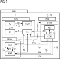
- the plant ontology PON is further divided into a structural ontology STON and a process ontology PRON (FIG. Fig. 2 ).
- the structural ontology defines different types of basic information.
- a component taxonomy is defined, which identifies classes of components and names and arranges them in a hierarchy.
- the structural ontology describes the topology of the plant, which is achieved via a hierarchy that determines which components are included in other components.
- part-of abbreviated po
- structural ontology defines properties of components via attributes.
- the namespace of the structural ontology is "pl:”.
- the process ontology PRON specifies the material that is processed by activities of the plant and manipulated by components of the plant during the entire production process.
- the namespace of the process ontology is "pr:”.
- the rule ontology PON uses concepts needed to specify basic rules for detecting states of the monitored elements of the other ontologies.
- This rule ontology is an essential part of the system according to the invention, since it is needed for the creation and further processing of the rules.
- the namespace of the rule ontology is "mon:”.
- the following German terms for the concepts are equivalent to the English terms in brackets.
- Activity occurrence ACO activity occurrence
- An action that is instantiated at a specific location and time eg, corresponds to "m1RunFast being executed by engine m1 at 2:00 pm on May 25, 2013" when the activity "m1RunFast” occurs.
- Component COM Component
- This concept describes a single or a compound component in the plant. The components can participate in activities via the relation pi. Each system consists of several components, eg the component "Motor m1" is part of the workcell 1.
- the class material is either a natural resource NAR, a product PRO or an auxiliary material AUM.
- An example of a natural resource is energy.
- Material occurrence MAO material occurrence
- This class refers to material that is processed in an installation at a specific location and at a specific time, eg "a part of a vehicle that is being transported by a conveyor belt at 2 pm on 24 June 2013".
- Attribute ATT attributes
- Attribute occurrence ATO attribute occurrence
- This class describes a property of an item that is instantiated at a given time, eg, "an engine m1 has the input power of 500W at 2:00 pm on May 25, 2013".
- a rule the expert can select all elements related to the component m1, in particular the just-mentioned attributes or processes "powerM1" and "RunFast". Based on this, he can then specify a rule, such as rule RU1, which is described below Fig. 6 is shown.
- Rule RU1 which is described below Fig. 6 is shown.
- the system can then verify various specifications via an axiom, eg by means of an axiom, which states that all monitored conditions that are linked via the relation lo to a rule (in this case RU1) only have one relation structural-relation (str) to the objects to which the monitored element (in this case m1) refers.
- a user may use the rule ontology concepts to manually construct states, supervised conditions, or rules.
- Such taxonomies have several advantages. On the one hand, higher reusability of the monitored rules is achieved due to the common information structures as new rules are designed by the user. On the other hand, the collaboration between different experts is facilitated, as the automatic selection of objects with identical meanings is simplified.
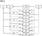
- Fig. 5 shows a schematic representation of a possible extension of in Fig. 4 shown ontology, wherein a taxonomy of the monitored condition CO is formed.
- the class of the monitored condition CO contains the subclasses PRC (Process Condition), ATC (Attribute Condition), STC (Condition Condition), and MAC (Material Condition).
- PRC Process Condition
- ATC Attribute Condition
- STC Supplement Condition
- MAC Mediation Condition
- These Conditions are associated with subclasses of the class Element EL and the class Occurrence OC, namely the classes ACT, ACO, ATT, ATO, ST, STO, MAT, MAO, which have already been described above.
- the relation mac means that the component COM processes the material occurrence MAC.
- the individual classes PRC, ATC, STC and MAC have relations with the subclasses of the class Element EL and the class Occurrence OC.
- the relations acr, acop, atr, atop, sr, sop, mr and mop are used.
- the rule ontology can be extended to different technical domains by adding domain-specific classes.
- the process condition PRC is a subclass of the monitored condition CO.
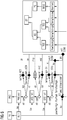
- Fig. 6 exemplifies one via the user interface UI in the KB knowledge base Fig. 1 instantiated rule RU1 with respect to the motor m1.
- the rule contains the process condition PRC-m1, the attribute condition ATC-m1 and the condition STC-m1.
- the presentation of the Fig. 6 is well known to those skilled in the art and is based on OWL. In this case, rectangular boxes denote OWL classes, black diamonds OWL individuals, white diamonds anonymous OWL individuals, solid arrows OWL object properties, and dashed arrows OWL data type properties.
- Fig. 6 contains the type declarations RDF: type as well as the known relation differentFrom from the OWL namespace.
- the component wc1 designates the workcell 1 and the activity occurrence ProcessOccM1, the attribute occurrence InputPowerM1, the state TempTooHigh and the state occurrence StateOccWc1 exist.
- the state powTooHigh_RunFast_TempTooHigh exists.
- the relation mip denotes the maximum input power.
- a taxonomy of states reproduced via the user interface UI Fig. 1 can be determined by a user.
- PowTooHigh designates the condition with too high power of the motor m1, TempTooHigh the condition with too high temperature of the motor m1 and TempTooLow the condition with too low temperature of the motor m1.
- RunFast refers to the condition of a high-speed engine.
- the state PowTooHigh is a subclass of the power state POS.
- the states TempTooHigh and TempTooLow are subclasses of the temperature state TES.
- the states POS and TES are in turn subclasses of the attribute state AS, which in turn is a subclass of the state ST.
- the RunFast state is a subclass of the engine state MOS, which is a subclass of the process state PS, which in turn is a subclass of state ST.
- the rule illustrated in FIG. 1 indicates that "If an engine m1 performs an activity corresponding to the activity RunFast and the measured value of the input power is greater than 400, and m1 is a part of the component of the workcell 1 having the identity wc1 that is currently in a state is too high temperature TempTooHigh, then the state of the motor m1 is set to PowTooHigh_RunFast_TempTooHigh, which means that the power consumption and the ambient temperature of the motor during the process RunFast are too high.
- a rule Rulel derives the condition TempTooHigh and a rule Rule2 derives the condition TempTooLow
- a suitable OWL-DL reasoner such as Pellet.
- Another example of a verification task is the identification of rules that can never be executed. This is the case, for example, when rules use inverse supervised conditions. This applies, for example, when a rule contains the two conditions "temperature of m1 greater than 20 ° C" and "temperature of m1 less than 20 ° C". Even such inverse conditions within a rule are recognized by a suitable reasoner.
- Reasoner REA used can also perform a classification.
- known classification mechanisms of OWL reasoners are used to structure the rules RU and the monitored conditions CO into different classification hierarchies or taxonomies.
- rules can be structured by identifying subtypes of monitored conditions.
- a rule Rulel may be classified as a subtype of another rule Rule2 if the rule Rulel uses a subset of the rule Rule2 CO conditions.
- An example of an implementation of this classification task is as follows: If the rule Rulel off Fig. 6 has three conditions, while another rule Rule2 has only two of these conditions, the rule Rulel is classified as a subtype of rule Rule2 by an OWL reasoner.
- redundant rules can also be identified. The reasoner checks in this case whether some rules in rule ontology have equivalent conditions and infer the same states. These rules are then considered equivalent by the reasoner.
- queries QUE can also be directed by a user to the ontology ON2.
- SPARQL queries are processed. For example, a user may wish to replace all M1FK7 engines in the plant with new M1PH8 engines with less power consumption. Using a corresponding query in ontology ON2, he can then identify all the rules that contain the engine of type M1FK7 and refer to the power consumption POS. In the Fig. 6 The shown taxonomy of states can be used within this query. Queries can also be used to filter meta-information and analyze data.
- Fig. 1 shown conversion of the knowledge base KB or ontology ON1 into executable rules EXR can be described as a workflow.
- both the plant ontology PON and the rule ontology RON are defined via Semantic Mediawiki.
- These ontologies form the knowledge base KB, which is then converted into the plant-specific OWL ontology PSON by means of an export.
- the ontology ON2 is then derived from this ontology, which is then validated via the reasoner.
- a consistent ontology is finally created.
- the rules in the ontology PSON are mapped to the generic RIF format.
- the rules are translated into the RIF XML Serialization syntax.
- the translation takes place by means of XSLT with a suitable XSL stylesheet. It then obtains the RIF XML serialization syntax as shown in the W3C RIF standard.
- an XSLT processor such as Saxon, is used, which is parameterized with an XSL style sheet containing the XSLT translation specific to the RIF XML syntax.
- the XSL style sheet consists of a number of XML templates, which are consistent XML structures identify and specify appropriate RIF-specific code fragments into which the XML structures are translated.
- the RIF rules are finally converted via XSLT into specific rules of the language format of a rule engine RM.
- XSLT processing matching XML structures are determined and translated into rule code fragments.
- executable rules are obtained via the corresponding rules engine.
- the executable rules are based on the rule language Etalis.
- the embodiments of the invention described above have a number of advantages.
- a simple and efficient creation of rules for a technical installation is achieved via a user interface, the rules being presented as ontologies, in contrast to the prior art.
- This makes it possible to use knowledge-based reasoning or query mechanisms to check the rules appropriately, and in particular to verify and classify them.
- the verification result can be presented to the user, who can then make adjustments to the rules created in case of inconsistencies in the rule base.
- the system also enables automatic conversion of the rules from the ontology into suitable executable rules of a rule machine, which can subsequently be used simply and efficiently for monitoring or diagnosing the technical installation.
Landscapes
- Engineering & Computer Science (AREA)
- Theoretical Computer Science (AREA)
- Physics & Mathematics (AREA)
- General Physics & Mathematics (AREA)
- General Engineering & Computer Science (AREA)
- Data Mining & Analysis (AREA)
- Computational Linguistics (AREA)
- Automation & Control Theory (AREA)
- Life Sciences & Earth Sciences (AREA)
- Animal Behavior & Ethology (AREA)
- Databases & Information Systems (AREA)
- Evolutionary Computation (AREA)
- Computing Systems (AREA)
- Mathematical Physics (AREA)
- Software Systems (AREA)
- Artificial Intelligence (AREA)
- Information Retrieval, Db Structures And Fs Structures Therefor (AREA)
Description
Die Erfindung betrifft ein System zum rechnergestützten Erstellen von Regeln zur Überwachung und/oder Diagnose einer technischen Anlage, insbesondere einer industriellen Anlage, wie z.B. einer Fertigungs- bzw. Produktionsanlage.The invention relates to a system for the computer-aided creation of rules for monitoring and / or diagnosis of a technical installation, in particular an industrial installation, e.g. a production or production plant.
Zur Überwachung bzw. Diagnose von technischen Anlagen ist es erforderlich, basierend auf der Struktur der Anlage ein geeignetes Überwachungs- bzw. Diagnose-System zu erstellen, das im Betrieb der Anlage basierend auf Sensor-Signalen oder Prozessinformationen der Anlage Fehlfunktionen bzw. kritische Betriebszustände bzw. Ursachen hierfür feststellt.For monitoring or diagnosis of technical systems, it is necessary to create a suitable monitoring or diagnostic system based on the structure of the system, which in operation of the system based on sensor signals or process information of the system malfunction or critical operating conditions or Causes for this.
Aus dem Stand der Technik sind regelbasierte Überwachungssysteme bekannt, die ihr Verhalten basierend auf Regeln anpassen können, die es jedoch nicht ermöglichen, redundante Regeln zu identifizieren bzw. die Konsistenz von Regeln zu überprüfen oder die Regeln auf andere Weise zu analysieren.Rule-based monitoring systems are known in the art which can adapt their behavior based on rules which, however, do not allow to identify redundant rules or to check the consistency of rules or otherwise analyze the rules.
Die Dokumente
Aufgabe der Erfindung ist es, ein System zur Erstellung von Regeln zur Überwachung und/oder Diagnose einer technischen Anlage zu schaffen, in dem ein Benutzer beim Entwurf von Regeln einfach und flexibel unterstützt wird und die Regeln automatisch überprüft werden können.The object of the invention is to provide a system for the creation of rules for monitoring and / or diagnosis of a technical facility in which a user is easily and flexibly supported in the drafting of rules and the rules can be checked automatically.
Diese Aufgabe wird durch die unabhängigen Patentansprüche gelöst. Weiterbildungen der Erfindung sind in den abhängigen Ansprüchen definiert.This object is solved by the independent claims. Further developments of the invention are defined in the dependent claims.
Das erfindungsgemäße System umfasst eine digitale Wissensbasis in der Form einer ersten Ontologie. Ontologien sind hinlänglich aus dem Stand der Technik bekannt und repräsentieren semantisches Wissen in der Form von digitalen Daten. Hierfür nutzen Ontologien sog. Konzepte bzw. Klassen und Relationen zwischen den Konzepten sowie weitere Konstrukte, wie Inferenz- und Integritätsregeln zum Schlussfolgern und zur Gewährleistung ihrer Gültigkeit. Die erste Ontologie umfasst eine Anlagen-Ontologie, welche die technische Anlage basierend auf Konzepten und Relationen beschreibt, sowie eine Regel-Ontologie, welche als Konzepte Regeln umfasst und somit die Struktur der Regeln abbildet. Eine jeweilige Regel ist dabei über eine Bedingungs-Relation mit Konzepten in der Form von einer oder mehreren Bedingungen verknüpft, die auf ein oder mehrere Konzepte der Anlagen-Ontologie verweisen. Ferner ist eine jeweilige Regel über eine Konsequenz-Relation mit dem Konzept einer aus der oder den Bedingungen abgeleiteten Konsequenz (z.B. eines Zustands) verknüpft, die auf ein oder mehrere Konzepte der Anlagen-Ontologie verweist. Mit anderen Worten leitet eine jeweilige Regel eine Konsequenz in Bezug auf eine Anlagenkomponente dann ab, wenn der oder die Bedingungen der Regel erfüllt sind.The system according to the invention comprises a digital knowledge base in the form of a first ontology. Ontologies are well known in the art and represent semantic knowledge in the form of digital data. For this purpose, ontologies use so-called concepts or classes and relations between the concepts as well as other constructs, such as inference and integrity rules to infer and to ensure their validity. The first ontology comprises a plant ontology, which describes the technical plant based on concepts and relations, as well as a rule ontology, which as concepts comprises rules and thus depicts the structure of the rules. Each rule is linked via a condition relation to concepts in the form of one or more conditions that refer to one or more concepts of the plant ontology. Furthermore, a respective rule is linked via a consequence relation to the concept of a consequence (eg of a state) derived from the condition (s), which refers to one or more concepts of the plant ontology. In other words, each rule derives a consequence with respect to a plant component when the one or more conditions of the rule are met.
Das erfindungsgemäße System umfasst ferner eine Benutzerschnittstelle, über welche ein Benutzer die Regel-Ontologie durch Spezifikation von Regeln (insbesondere Instantiierung von Regeln) verändern kann, wodurch die erste Ontologie editiert wird. Darüber hinaus ist ein Reasoner (Schlussfolgerer) vorgesehen, wobei Reasoner zur Verarbeitung von Ontologien an sich bekannt sind. Der Reasoner wird auf eine zweite Ontologie angewendet. Die zweite Ontologie kann identisch mit der ersten editierten Ontologie sein oder mittels eines Ontologie-Transformationsmittels aus der ersten editierten Ontologie abgeleitet werden. Der Reasoner verifiziert die Regeln in der zweiten Ontologie und gibt das Verifikationsergebnis über die Benutzerschnittstelle aus. Dem Benutzer wird somit wiederholt die Möglichkeit gegeben, basierend auf dem Verifikationsergebnis des Reasoners über die Benutzerschnittstelle nochmals Änderungen an den Regeln vorzunehmen und dann den Reasoner wieder laufen zu lassen. Der Reasoner erkennt insbesondere redundante, ähnliche, widersprüchliche und inkonsistente Regeln, und diese fehlerhaften Regeln können durch einen Benutzer dann behoben werden.The system according to the invention further comprises a user interface, via which a user can change the rule ontology by specifying rules (in particular instantiation of rules), whereby the first ontology is edited. In addition, a reasoner (renter) is provided, with reasoners being known per se for processing ontologies. The reasoner is applied to a second ontology. The second ontology may be identical to the first edited ontology or derived from the first edited ontology using an ontology transformation means. The reasoner verifies the rules in the second ontology and outputs the verification result via the user interface. The user is thus repeatedly given the opportunity to make changes to the rules again based on the verification result of the reasoner via the user interface and then run the reasoner again. In particular, the reasoner recognizes redundant, similar, contradictory, and inconsistent rules, and these erroneous rules can then be remedied by a user.
Das erfindungsgemäße System umfasst ferner ein Regel-Generierungsmittel, um aus der ersten editierten Ontologie ausführbare Regeln zu generieren, die von einer Regel-Maschine (engl. Rule Engine) ausgeführt werden können. Auf diese Weise werden Regeln geschaffen, die anschließend im Betrieb der technischen Anlage mittels der Regel-Maschine verarbeitet werden können, wobei die Regel-Maschine basierend auf den Regeln kritische Zustände, Fehlzustände und dgl. der technischen Anlage erkennen kann bzw. diagnostizieren kann. Die Ausführung von Regeln basierend auf Regel-Maschinen ist dabei an sich aus dem Stand der Technik bekannt.The system according to the invention further comprises a rule generation means for generating from the first edited ontology executable rules that can be executed by a rule engine. In this way, rules are created which can subsequently be processed in the operation of the technical system by means of the control machine, wherein the control machine can recognize or diagnose critical states, fault conditions and the like of the technical system based on the rules. The execution of rules based on rule machines is known per se from the prior art.
Die Erfindung beruht auf der Erkenntnis, dass in einem regelbasierten Überwachungs- bzw. Diagnosesystem die Regeln basierend auf einer Ontologie repräsentiert werden können, was die Möglichkeit schafft, dass vom Benutzer erstellte Regeln automatisch mittels eines Reasoners analysiert werden können. Hierdurch wird ein verbessertes System zur Erstellung von benutzerspezifischen Regeln geschaffen, welche anschließend im Betrieb einer technischen Anlage zu deren Überwachung bzw. Diagnose genutzt weden können.The invention is based on the recognition that in a rule-based monitoring or diagnosis system the rules can be represented based on an ontology, which creates the possibility that rules created by the user can be automatically analyzed by means of a reasoner. As a result, an improved system for creating user-specific rules is created, which can then be used in the operation of a technical system for their monitoring or diagnosis.
In einer besonders bevorzugten Ausführungsform wird die erste Ontologie basierend auf einem Ontologie-Editor beschrieben und ist mit dem Ontologie-Editor editierbar. Zum Beispiel kann als Editor Semantic Mediawiki verwendet werden, das auf OWL/RDF basiert. Semantic Mediawiki ist ein an sich bekannter Editor aus dem Semantic Web Bereich, der auf Webseiten basiert. Mit diesem Editor kann besonders einfach eine Benutzerschnittstelle zum Editieren von Regeln geschaffen werden. Ggf. kann die erste Ontologie jedoch auch über andere Editoren, wie z.B. Protege, beschrieben werden.In a particularly preferred embodiment, the first ontology is described based on an ontology editor and is editable with the ontology editor. For example, the Editor can be Semantic Mediawiki based on OWL / RDF. Semantic Mediawiki is a well-known editor of the Semantic Web area, which is based on web pages. This editor is particularly easy to create a user interface for editing rules. Possibly. however, the first ontology can also be accessed via other editors, such as Protege.
In einer weiteren bevorzugten Ausführungsform wird die zweite Ontologie basierend auf der an sich bekannten Beschreibungssprache OWL (OWL - Ontology Web Language) realisiert.In a further preferred embodiment, the second ontology is realized based on the known description language OWL (OWL - Ontology Web Language).
In einer weiteren Variante des erfindungsgemäßen Systems umfasst die Anlagen-Ontologie eine strukturelle Ontologie und eine Prozess-Ontologie, wobei die strukturelle Ontologie Komponenten der Anlage sowie deren strukturellen Zusammenhänge und die Prozess-Ontologie durch die Komponenten der Anlage durchgeführte Prozesse beschreibt. Hierdurch können strukturiert die beim Betrieb einer Anlage ablaufenden Prozesse in der Ontologie abgebildet werden.In a further variant of the system according to the invention, the plant ontology comprises a structural ontology and a process ontology, wherein the structural ontology describes components of the plant as well as their structural relationships and the process ontology performed by the components of the plant processes. As a result, the processes occurring during the operation of an installation can be mapped in the ontology in a structured manner.
In einer weiteren Ausgestaltung ist das erfindungsgemäße System derart ausgestaltet, dass es zunächst die editierte erste Ontologie exportiert, wobei die exportierte Ontologie anschließend mit dem Ontologie-Transformationsmittel in die zweite Ontologie überführt wird. Insbesondere wird dabei die exportierte Ontologie mit einer generischen Ontologie zusammengefügt, wobei die generische Ontologie Axiome und Konzepte enthält, die im Rahmen der Verifikation durch den Reasoner benötigt werden. Das Zusammenfügen von Ontologien sowie die Definition einer geeigneten generischen Ontologie ist dabei an sich aus dem Stand der Technik bekannt bzw. liegt im Rahmen von fachmännischem Handeln (siehe z.B.
In einer weiteren Variante des erfindungsgemäßen Systems können über die Benutzerschnittstelle ferner Konzepte und Relationen der ersten Ontologie durch einen Benutzer spezifiziert werden. Hierdurch wird es ermöglicht, das System flexibel an beliebige technische Anlagen anzupassen.In a further variant of the system according to the invention, further concepts and relations of the first ontology can be specified by a user via the user interface. This makes it possible to adapt the system flexibly to any technical equipment.
Der im erfindungsgemäßen System verwendete Reasoner ist vorzugsweise ferner derart ausgestaltet, dass er die Konzepte in der zweiten Ontologie klassifiziert und das Klassifikationsergebnis über die Benutzerschnittstelle ausgibt. Hierdurch werden dem Benutzer hilfreiche Informationen über die technisehe Anlage bzw. die verarbeiteten Regeln gegeben, die er dann wiederum im Rahmen des Editierens der ersten Ontologie berücksichtigen kann.The reasoner used in the system according to the invention is preferably further configured such that it classifies the concepts in the second ontology and outputs the classification result via the user interface. This provides the user with helpful information about the technology Attachment or the processed rules given, which he then again in the context of editing the first ontology can be considered.
In einer weiteren Ausführungsform des erfindungsgemäßen Systems ist die Benutzerschnittstelle derart ausgestaltet, dass ein Benutzer Abfragen an die zweite Ontologie richten kann, wobei die Abfrageergebnisse über die Benutzerschnittstelle ausgegeben werden. Vorzugsweise werden dabei Abfragen in der an sich bekannten Abfragesprache SPARQL verarbeitet. Gemäß dieser Variante kann der Benutzer die zweite Ontologie basierend auf seinen Wünschen geeignet analysieren.In a further embodiment of the system according to the invention, the user interface is configured such that a user can direct queries to the second ontology, the query results being output via the user interface. Preferably, queries are processed in the known query language SPARQL. According to this variant, the user can appropriately analyze the second ontology based on his wishes.
In einer weiteren, besonders bevorzugten Ausführungsform ist das Regel-Generierungsmittel derart ausgestaltet, dass es zunächst Regeln in der an sich bekannten RIF-XML-Serialization-Syntax erzeugt und die Regeln dieser Syntax anschließend in die ausführbaren Regeln des Formats der Regel-Maschine übersetzt, wobei entsprechende Übersetzungsalgorithmen an sich bekannt sind. Das Format der Regel-Maschine ist dabei z.B. das Etalis-Format. Mit dieser Variante erfolgt eine Wandlung in das generische RIF-Format, was es ermöglicht, das System flexibel an verschiedene Formate unterschiedlicher Regel-Maschinen anzupassen.In a further, particularly preferred embodiment, the rule generation means is designed in such a way that it first generates rules in the per se known RIF XML serialization syntax and then translates the rules of this syntax into the executable rules of the format of the rule machine, where appropriate translation algorithms are known per se. The format of the rule machine is e.g. the Etalis format. With this variant, a conversion into the generic RIF format takes place, which makes it possible to adapt the system flexibly to different formats of different rule machines.
In einer Ausführungsform des erfindungsgemäßen Systems ist das System dazu eingerichtet, zur Überwachung und/oder Diagnose der technischen Anlage während des Betriebs der technischen Anlage die generierten ausführbaren Regeln über die Regel-Maschine auszuführen.In one embodiment of the system according to the invention, the system is configured to execute the generated executable rules via the control machine for monitoring and / or diagnosis of the technical system during operation of the technical system.
Die Erfindung betrifft ferner ein Verfahren zum rechnergestützten Erstellen von Regeln zur Überwachung und/oder Diagnose einer technischen Anlage mittels des oben beschriebenen erfindungsgemäßen Systems. Dabei wird eine digitale Wissensbasis in der Form einer ersten Ontologie bereitgestellt, wobei die erste Ontologie eine Anlagen-Ontologie umfasst, welche die technische Anlage basierend auf Konzepten und Relationen beschreibt, sowie eine Regel-Ontologie, welche als Konzepte Regeln umfasst, wobei eine jeweilige Regel über eine Bedingungs-Relation mit Konzepten in der Form von einer oder mehreren Bedingungen verknüpft ist, die auf eine oder mehrere Konzepte der Anlagen-Ontologie verweisen, und über eine Konsequenz-Relation mit dem Konzept einer aus der oder den Bedingungen abgeleiteten Konsequenz verknüpft ist, die auf eine oder mehrere Konzepte der Anlagen-Ontologie verweist. Ferner wird eine Benutzerschnittstelle bereitgestellt, über welche ein Benutzer die Regel-Ontologie durch Spezifikation von Regeln verändern kann, wodurch die erste Ontologie editiert wird.The invention further relates to a method for computer-aided creation of rules for monitoring and / or diagnosis of a technical installation by means of the system according to the invention described above. In this case, a digital knowledge base is provided in the form of a first ontology, wherein the first ontology comprises a plant ontology which describes the technical plant based on concepts and relations describes, as well as a rule ontology, which as concepts comprises rules, wherein a respective rule is linked via a condition relation with concepts in the form of one or more conditions, which refer to one or more concepts of the plant ontology, and a consequence relation is linked to the concept of a consequence derived from the condition (s), which refers to one or more concepts of the plant ontology. Furthermore, a user interface is provided by which a user can change the rule ontology by specifying rules, thereby editing the first ontology.
Im Rahmen des obigen Verfahrens wird ein Reasoner auf eine zweite Ontologie angewendet, welche mittels eines Ontologie-Transformationsmittels aus der ersten editierten Ontologie abgeleitet ist oder welche die erste editierte Ontologie ist, wobei der Reasoner die Regeln in der zweiten Ontologie verifiziert und das Verifikationsergebnis über die Benutzerschnittstelle ausgibt. Ferner generiert ein Regel-Generierungsmittel aus der ersten editierten Ontologie ausführbare Regeln, die von einer Regel-Maschine ausgeführt werden können.In the above method, a reasoner is applied to a second ontology derived from the first edited ontology by means of an ontology transforming means, or which is the first edited ontology, the reasoner verifying the rules in the second ontology and verifying the verification result via the ontology Outputs user interface. Furthermore, a rule generation means generates executable rules that can be executed by a rule engine from the first edited ontology.
Alle im Vorangegangenen beschriebenen bevorzugten Varianten des erfindungsgemäßen Systems können analog auch in dem oben beschriebenen erfindungsgemäßen Verfahren implementiert werden.All of the preferred variants of the system according to the invention described above can be implemented analogously in the method according to the invention described above.
Eine Variante des erfindungsgemäßen Verfahrens betrifft darüber hinaus ein Verfahren, wobei ausführbare Regeln, die mit dem oben beschriebenen erfindungsgemäßen System erstellt sind bzw. werden, während des Betriebs der technischen Anlage über eine Regel-Maschine ausgeführt werden.A variant of the method according to the invention also relates to a method, wherein executable rules, which are or are created with the inventive system described above, are executed during the operation of the technical system via a control machine.
Die Erfindung umfasst ferner ein Computer-Programmprodukt mit einem auf einem maschinenlesbaren Träger gespeicherten Programmcode zur Durchführung des oben beschriebenen erfindungsgemäßen Verfahrens zum Erstellen von Regeln bzw. des oben beschriebenen erfindungsgemäßen Verfahrens zur Überwachung und/oder Diagnose einer technischen Anlage, wenn der Programmcode auf einem Computer ausgeführt wird.The invention further comprises a computer program product having a program code stored on a machine-readable medium for carrying out the above-described method according to the invention for creating rules or the method according to the invention for monitoring and / or diagnosing a technical installation described above, when the program code is executed on a computer.
Ausführungsbeispiele der Erfindung werden nachfolgend anhand der beigefügten Figuren detailliert beschrieben.Embodiments of the invention are described below in detail with reference to the accompanying drawings.
Es zeigen:
- Fig. 1
- eine schematische Darstellung einer Ausführungsform des erfindungsgemäßen Systems zur Erstellung von Regeln;
- Fig. 2
- eine schematische Darstellung der in der Wissensbasis aus
Fig. 1 enthaltenen Ontologie; - Fig. 3
- eine detaillierte Darstellung der in
Fig. 2 enthaltenen Anlagen-Ontologie; - Fig. 4
- eine detaillierte Darstellung der in
Fig. 2 enthaltenen Regel-Ontologie; - Fig. 5
- eine schematische Darstellung einer Klassifikation des Konzepts der Bedingung aus der Regel-Ontologie der
Fig. 4 ; und - Fig. 6
- eine schematische Darstellung eines Beispiels einer Regel, die in der Ontologie ON2 aus
Fig. 1 enthalten ist.
- Fig. 1
- a schematic representation of an embodiment of the system according to the invention for creating rules;
- Fig. 2
- a schematic representation of the in the knowledge base
Fig. 1 contained ontology; - Fig. 3
- a detailed presentation of in
Fig. 2 contained plant ontology; - Fig. 4
- a detailed presentation of in
Fig. 2 contained rule ontology; - Fig. 5
- a schematic representation of a classification of the concept of the condition from the rule ontology of
Fig. 4 ; and - Fig. 6
- a schematic representation of an example of a rule in the ON2 ontology
Fig. 1 is included.
Im Folgenden wird ein Ausführungsbeispiel der Erfindung basierend auf der Überwachung bzw. Diagnose einer technischen Anlage in der Form einer industriellen Anlage beschrieben, bei der es sich z.B. um eine Fertigungsstraße oder um eine andere Anlage zur Herstellung von Produkten handeln kann. In der Regel umfasst die Überwachung einer industriellen Anlage die Ableitung von Gerätezuständen der industriellen Anlage, um die Wartung dieser Geräte geeignet zu planen. Ferner beinhaltet die Überwachung meist auch eine sog. Prozess-Überwachung, bei der bestimmte Prozesse, die im Betrieb der Anlage durchgeführt werden, überwacht werden, um deren korrekte Ausführung zu gewährleisten. Ferner beinhaltet die Überwachung einer industriellen Anlage in der Regel auch eine Energie-Überwachung, welche den aktuellen Energieverbrauch der Anlage im Vergleich zu einem erwarteten Energieverbrauch analysiert. Die Betreiber einer industriellen Anlage müssen somit eine Vielzahl von verschiedenartigen Überwachungsaufgaben durchführen. Die im Folgenden beschriebene Ausführungsform stellt dabei ein System bereit, mit dem entsprechende Regeln zur Überwachung der Anlage einfach und effizient erstellt, verwaltet und ausgeführt werden können.In the following an embodiment of the invention based on the monitoring or diagnosis of a technical system in the form of an industrial plant is described, which may be, for example, a production line or other plant for the production of products. As a rule, the monitoring includes an industrial plant the derivation of device states of the industrial plant in order to plan the maintenance of these devices appropriately. Furthermore, the monitoring usually also includes a so-called process monitoring, in which certain processes that are carried out during operation of the system are monitored to ensure their correct execution. Furthermore, the monitoring of an industrial plant usually also includes an energy monitoring, which analyzes the current energy consumption of the plant compared to an expected energy consumption. The operators of an industrial plant thus have to perform a variety of different types of monitoring tasks. The embodiment described below provides a system with which appropriate rules for monitoring the system can be easily and efficiently created, managed and executed.
Gemäß der Ausführungsform der
Wie sich aus den obigen Ausführungen ergibt, kann somit ein Benutzer, wie z.B. ein Ingenieur mit Wissen über die Anlage, sein Wissen in der Form einer Ontologie-Bibliothek ON1 in der Wissensbasis KB ablegen bzw. editieren. Die Wissensbasis enthält Ontologien, welche den Ingenieur unterstützen, hierauf anlagen-spezifische Ontologien durch Bearbeiten der Wissensbasis zu generieren. Der Benutzer hat dabei die Möglichkeit, entweder zusätzliche Konzepte zu der Bibliothek hinzuzufügen oder Konzepte auf bereits bestehende Konzepte in der Bibliothek abzubilden. Hierdurch wird die Flexibilität und Anpassbarkeit der Wissensbasis gewährleistet.As can be seen from the above, a user, e.g. an engineer with knowledge of the plant, to deposit or edit his knowledge in the form of an ontology library ON1 in the KB knowledge base. The knowledge base includes ontologies that assist the engineer to generate plant-specific ontologies by manipulating the knowledge base. The user has the option of either adding additional concepts to the library or mapping concepts to existing concepts in the library. This ensures the flexibility and adaptability of the knowledge base.
In der hier beschriebenen Ausführungsform wird zum Editieren der Wissensbasis KB bzw. der Ontologie ON1 der an sich bekannte Editor "Semantic Mediawiki (SMW)" verwendet, der die Ontologie-Bibliothek in entsprechende RDF-Modelle (RDF = Resource Description Framework) umsetzt, welche es einem Benutzer ermöglichen, strukturiertes Wissen über die Anlage in der Form von Webseiten zu erzeugen und zu editieren. Semantic Mediawiki unterstützt dabei Experten in ihrer Aufgabe, Daten der Anlage und Regeln zur Überwachung bzw. Diagnose der Anlage zu modellieren. Ferner ermöglicht Semantic Mediawiki die Visualisierung und Navigation in entsprechenden modellierten Daten über die technische Anlage. Mit der Komponente RUEN und der zugeordneten Schnittstelle UI wird somit einem Experten ermöglicht, die der Überwachung bzw. Diagnose zugrunde liegende technische Anlage näher zu spezifizieren und entsprechende Regeln zur Überwachung bzw. zur Diagnose der Anlage festzulegen.In the embodiment described here, for editing the knowledge base KB or the ontology ON1, the known editor "semantic media wiki (SMW)" is used, which converts the ontology library into corresponding RDF models (RDF = Resource Description Framework), which allow a user to create and edit structured knowledge about the asset in the form of web pages. Semantic Mediawiki supports experts in their task of modeling plant data and rules for monitoring or diagnosing the plant. Furthermore, Semantic Mediawiki enables the visualization and navigation in corresponding modeled data about the technical system. With the component RUEN and the associated interface UI, an expert is thus enabled to specify the technical system underlying the monitoring or diagnosis in more detail and to define corresponding rules for monitoring or diagnosing the system.
Gemäß der Ausführungsform der
Ein Vorteil der Verwendung von Semantic Mediawiki besteht ferner darin, dass die Zusammenarbeit von verschiedenen Experten ermöglicht wird, welche mit unterschiedlichen Aspekten der Anlage vertraut sind. Zum Beispiel können Hersteller von Komponenten der Anlage allgemeine Überwachungsregeln für diese Komponenten spezifizieren, da sie vertieftes Wissen haben, welches zur Überwachung der Komponenten benötigt wird. Ein weiterer Vorteil von Semantic Mediawiki besteht darin, dass es zum einen eine Gesamtübersicht über alle Aspekte der überwachten Anlage mit Navigationslinks liefert und zum anderen spezifische Aspekte der Anlage mit sog. ASK-Abfragen gefiltert werden können.An advantage of using Semantic Mediawiki is also that it enables collaboration by different experts who are familiar with different aspects of the installation. For example, manufacturers of components of the plant may specify general monitoring rules for these components because they have in-depth knowledge needed to monitor the components. Another advantage of Semantic Mediawiki is that it provides an overview of all aspects of the monitored site with navigational links and filters specific aspects of the site with so-called ASK queries.
In der Ausführungsform der
Der Reasoner REA wird auf die Ontologie ON2 angewendet, wie durch den Pfeil P4 angedeutet ist. Der Reasoner verifiziert dabei die in der Ontologie ON2 enthaltenen Regeln, indem er semantisch nicht korrekte Regeln identifiziert. Ferner klassifiziert er die Regeln, indem er sie in einer strukturierten Taxonomie (d.h. Klassifikation) anordnet. Das entsprechende Verifikations- und Klassifikationsergebnis wird wiederum über die Benutzerschnittstelle UI ausgegeben. Der Benutzer kann dann basierend auf dem angezeigten Ergebnis entsprechende Widersprüche in der ursprünglichen Wissensbasis bzw. darin enthaltene Fehler korrigieren. In der Ausführungsform der
Gemäß der Ausführungsform der
Als Ergebnis können entsprechende Überwachungs- oder Diagnosezustände der technischen Anlage und deren Komponenten bei deren Betrieb basierend auf Sensordaten oder Prozessdaten mithilfe der ausführbaren Regeln abgeleitet werden. Es können somit z.B. Warnmeldungen ausgegeben werden, sofern im Betrieb der technischen Anlage kritische Zustände auftreten. Ebenso können über die ausführbaren Regeln z.B. Diagnosedaten der technischen Anlage gewonnen werden. Durch die Zwischenwandlung der Regeln in das RIF-Format wird die Flexibilität des Systems erhöht, da der Benutzer eine geeignete Regel-Maschine in Abhängigkeit von den Anlagen-spezifischen Gegebenheiten auswählen kann. Falls das System z.B. Echtzeit-Ereignisse überwachen soll, kann er eine komplexere CEP (Complex Event Processing) Regel-Maschine, wie z.B. Drools Fusion, verwenden.As a result, corresponding monitoring or diagnostic states of the technical installation and their components can be derived in their operation based on sensor data or process data using the executable rules. Thus, e.g. Warning messages are issued if critical conditions occur during operation of the technical system. Likewise, via the executable rules, e.g. Diagnostic data of the technical system are obtained. By interposing the rules into the RIF format, the flexibility of the system is increased because the user can select a suitable rule machine depending on the plant-specific circumstances. If the system is e.g. To monitor real-time events, it can use a more complex complex event processing (CEP) rule engine, such as Drool's Fusion, use.
Im Folgenden werden die in der Wissensbasis KB enthaltenen Ontologien PON und RON näher erläutert. Die nachfolgend beschriebenen Ontologien beruhen zum Teil auf Ontologie-Mustern von bekannten Ontologie-Quellen. Zum Beispiel basieren sie auf der Process Specification Language (PSL), welche semantischen Konzepte in Bezug auf den durch die Anlage durchgeführten Prozess identifiziert, formal definiert und strukturiert. Die Anlagen-Ontologie PON enthält semantisches Wissen über die spezifische Anlage, wie z.B. über Verbindungen zwischen Komponenten der Anlage oder über Produkte, welche durch die Anlage hergestellt werden. Demgegenüber enthält die Regel-Ontologie RON Regeln zur Erkennung von Zuständen in der Anlage, wie z.B. eine Regel zum Ableiten des Zustands "powerTooHigh" (d.h. zu hohe elektrische Leistung) für einen Motor m1 der Anlage.In the following, the ontologies PON and RON contained in the knowledge base KB are explained in more detail. The ontologies described below are based in part on ontology patterns from known ontology sources. For example, they are based on the Process Specification Language (PSL), which identifies, formally defines and structures semantic concepts related to the process performed by the plant. The plant ontology PON contains semantic knowledge of the specific plant, such as about connections between components of the plant or about products made by the plant. On the other hand, the rule ontology RON contains rules for detecting conditions in the plant, e.g. a rule for deriving the state "powerTooHigh" (i.e., too high electric power) for a motor m1 of the plant.
Die Anlagen-Ontologie PON wird in der hier beschriebenen Ausführungsform ferner nochmals aufgeteilt in eine strukturelle Ontologie STON und eine Prozess-Ontologie PRON (
Die Prozess-Ontologie PRON spezifiziert das Material, das durch Aktivitäten der Anlage verarbeitet und durch Komponenten der Anlage während des gesamten Produktionsprozesses manipuliert wird. Der Namensraum der Prozess-Ontologie ist "pr:".The process ontology PRON specifies the material that is processed by activities of the plant and manipulated by components of the plant during the entire production process. The namespace of the process ontology is "pr:".
Im Unterschied zu den obigen Ontologien STON und PRON verwendet die Regel-Ontologie PON Konzepte, welche benötigt werden, um grundlegende Regeln zur Erkennung von Zuständen der überwachten Elemente der anderen Ontologien zu spezifizieren. Diese Regel-Ontologie ist ein wesentlicher Bestandteil des erfindungsgemäßen Systems, da sie zum Erstellen und zum Weiterverarbeiten der Regeln benötigt wird. Der Namensraum der Regel-Ontologie ist "mon:".Unlike the STON and PRON ontologies above, the rule ontology PON uses concepts needed to specify basic rules for detecting states of the monitored elements of the other ontologies. This rule ontology is an essential part of the system according to the invention, since it is needed for the creation and further processing of the rules. The namespace of the rule ontology is "mon:".
- Relation sb (= specified-by), die festlegt, durch welches Attribut ATT eine Komponente COM spezifiziert wird;
- Relation mo (= monitors), welche festlegt, welches Element EL durch die Komponente COM überwacht wird;
- Relation pi (= participates-in), welche festlegt, an welcher Aktivität ACT eine Komponente COM beteiligt ist;
- Relation hp (= has-participant), welche festlegt, welche Komponente COM an einer Aktion ACT beteiligt ist;
- Relation pro (= processes), welche festlegt, welche Aktivität ACT ein Material MAT verarbeitet;
- Relation ipr (= is-processed), welche festlegt, welches Material MAT durch eine Aktivität ACT verarbeitet wird;
- Relation ma (= manipulates), welche festlegt, welche Komponente COM ein Material MAT verarbeitet;
- Relation ima (= is-manipulated-by), welche festlegt, welches Material MAT durch eine Komponente COM manipuliert (verarbeitet) wird;
- Relation bo (= body), welche einer if-Relation entspricht und eine Bedingung CO der entsprechenden Regel RU festlegt;
- Relation he (= head), welche einer then-Relation entspricht und festlegt, welcher Zustand ST aufgrund der Regel RU beim Eintritt der über die Relation bo spezifizierten Bedingung CO eintritt;
- Relation ri (= resides-in), welche festlegt, welcher Zustand ST durch ein Element EL eingenommen wird.
- Relation sb (= specified-by), which determines by which attribute ATT a component COM is specified;
- Relation mo (= monitors), which determines which element EL is monitored by the component COM;
- Relation pi (= participates-in), which determines which activity ACT a component COM is involved in;
- Relation hp (= has-participant), which determines which component COM participates in an action ACT;
- Relation pro (= processes), which determines which activity ACT processes a material MAT;
- Relation ipr (= is-processed), which determines which material MAT is processed by an activity ACT;
- Relation ma (= manipulates), which determines which component COM processes a material MAT;
- Relation ima (= is-manipulated-by), which determines which material MAT is manipulated (processed) by a component COM;
- Relation bo (= body), which corresponds to an if relation and defines a condition CO of the corresponding rule RU;
- Relation he (= head), which corresponds to a then relation and determines which state ST is due to the rule RU occurs upon the occurrence of the condition CO specified via the relation bo;
- Relation ri (= resides-in), which determines which state ST is occupied by an element EL.
Im Speziellen enthält die Anlagen-Ontologie PON der
- Die Klasse ATO, welche dem oben beschriebenen Attribut-Auftreten entspricht;
- die Klasse ACO, welche dem oben beschriebenen Aktivitäts-Auftreten entspricht;
- die Klasse MAO, welche dem oben beschriebenen Material-Auftreten entspricht;
- die Klasse NAR, welche der oben beschriebenen natürlichen Ressource entspricht;
- die Klasse PRO, welche dem oben beschriebenen Produkt entspricht;
- die Klasse AUM, welche dem oben beschriebenen Hilfsmaterial entspricht;
- die Relation ato (= attribute-occurence-of), welche spezifiziert, welches Attribut ATT in der Klasse ATO vorkommt;
- die Relation aco (= activity-occurence-of), welche spezifiziert, welche Aktivität ACT in der Klasse ACO vorkommt;
- die Relation mao (= material-occurence-of), welche spezifiziert, welches Material MAT in der MAO vorkommt;
- die Relation po/ct (= part-of/connected-to), welche spezifiziert, von welcher übergeordneten Komponente die Komponente COM Teil ist bzw. mit welcher Komponente die Komponente COM verbunden ist.
- The class ATO corresponding to the attribute occurrence described above;
- the class ACO, which corresponds to the activity occurrence described above;
- the class MAO, which corresponds to the material occurrence described above;
- the class NAR, which corresponds to the natural resource described above;
- the class PRO, which corresponds to the product described above;
- the class AUM, which corresponds to the auxiliary material described above;
- the relation ato (= attribute-occurrenceence-of), which specifies which attribute ATT occurs in the class ATO;
- the relation aco (= activity-occurrenceence-of), which specifies which activity ACT occurs in class ACO;
- the relation mao (= material-occurrenceence-of), which specifies which MAT material occurs in the MAO;
- the relation po / ct (= part-of / connected-to), which specifies from which superordinate component the component COM is part or to which component the component COM is connected.
Einige der Konzepte der oben beschriebenen Anlagen-Ontologie bauen auf Ontologie-Muster von verfügbaren Ontologie-Quellen auf, wie z.B. die Konzepte "Aktivität" und "Aktivitäts-Auftreten" mit entsprechenden Axiomen aus der PSL-Ontologie. Alle anderen Konzepte wurden extrahiert, indem verschiedene Produktionsanlagen analysiert wurden, bekannte Standards im Bereich der Herstellung (z.B. CAEX für eine Anlagen-Struktur) überprüft wurden und Interviews mit Experten durchgeführt wurden. Einige Konzepte der in
In der nachfolgenden Tabelle sind Konzepte wiedergegeben, die in der Regel-Ontologie RON enthalten sind. Die nachfolgend genannten deutschen Begriffe für die Konzepte sind dabei äquivalent zu den in Klammern genannten englischen Begriffen.
- RU entspricht dem oben erläuterten Konzept einer Regel;
- CO entspricht dem oben erläuterten Konzept einer überwachten Bedingung;
- ST entspricht dem oben erläuterten Konzept eines Zustands;
- EL entspricht dem oben erläuterten Konzept eines Elements;
- OC entspricht dem oben erläuterten Konzept eines Auftretens;
- STO entspricht dem oben erläuterten Konzept eines Zustand-Auftretens;
- TP entspricht dem oben erläuterten Konzept eines Zeitpunkts;
- MEL entspricht dem oben erläuterten Konzept eines überwachten Elements;
- lo (= logical operator) entspricht einem logischen Operator, wie AND oder OR;
- re (= reference) entspricht der oben erläuterten Relation "reference" und verweist auf ein Element EL;
- op (= operator) entspricht der Relation "operator" und verweist auf ein Auftreten OC;
- so(= state-occurence-of) entspricht der Relation des Auftretens eines Zustands;
- io(= is-occuring-at) entspricht der Relation des Auftretens eines Zustands zu einer bestimmten Zeit.
- RU corresponds to the concept of a rule explained above;
- CO corresponds to the above-discussed concept of a monitored condition;
- ST corresponds to the concept of a state explained above;
- EL corresponds to the concept of an element explained above;
- OC corresponds to the above-described concept of occurrence;
- STO corresponds to the concept of a state occurrence explained above;
- TP corresponds to the concept of a time point explained above;
- MEL corresponds to the above-discussed concept of a monitored element;
- lo (= logical operator) corresponds to a logical operator, such as AND or OR;
- re (= reference) corresponds to the relation "reference" explained above and refers to an element EL;
- op (= operator) corresponds to the relation "operator" and refers to an occurrence OC;
- so (= state-occurrence-of) corresponds to the relation of the occurrence of a state;
- io (= is-occuring-at) corresponds to the relation of the occurrence of a state at a certain time.
Die weiteren, in
Über die Regel-Ontologie gemäß
Zusätzlich kann ein Benutzer die Konzepte der Regel-Ontologie nutzen, um manuell Taxonomien von Zuständen, überwachten Bedingungen oder Regeln zu konstruieren. Solche Taxonomien weisen verschiedene Vorteile auf. Zum einen wird eine höhere Wiederverwendbarkeit der überwachten Regeln aufgrund der gemeinsamen Informationsstrukturen erreicht, wenn neue Regeln durch den Benutzer entworfen werden. Zum anderen wird die Zusammenarbeit zwischen verschiedenen Experten erleichtert, da die automatische Auswahl von Objekten mit identischen Bedeutungen vereinfacht wird.Additionally, a user may use the rule ontology concepts to manually construct states, supervised conditions, or rules. Such taxonomies have several advantages. On the one hand, higher reusability of the monitored rules is achieved due to the common information structures as new rules are designed by the user. On the other hand, the collaboration between different experts is facilitated, as the automatic selection of objects with identical meanings is simplified.
Die Bedeutung dieser Relationen ist wie folgt:
- acr (= activityRef) stellt eine Referenz re auf eine Aktivität ACT dar;
- acop (= activityOp) stellt einen Operator op für ein Aktivitäts-Auftreten ACO dar;
- atr (= attributeRef) stellt eine Referenz re auf ein Attribut ATT dar;
- atop (= attributeOp) stellt einen Operator op für ein Attribut-Auftreten ATO dar;
- sr (= stateRef) stellt eine Referenz re auf einen Zustand ST dar;
- sop (= stateOp) stellt einen Operator op für ein Zustands-Auftreten STO dar;
- mr (= materialRef) stellt eine Referenz re auf ein Material MAT dar;
- mop (= materialOp) stellt einen Operator op für ein Material-Auftreten MAO dar.
- acr (= activityRef) represents a reference to an ACT activity;
- acop (= activityOp) represents an operator op for an activity occurrence ACO;
- atr (= attributeRef) represents a reference to an ATT attribute;
- atop (= attributeOp) represents an operator op for an attribute occurrence ATO;
- sr (= stateRef) represents a reference to a state ST;
- sop (= stateOp) represents an operator op for a state occurrence STO;
- mr (= materialRef) represents a reference to a material MAT;
- mop (= materialOp) represents an operator op for a material occurrence MAO.
Mit der in
Darüber hinaus ist in
Die in
In Folgenden wird beschrieben, wie mit dem in
Der in
Wie aus
Die in
Die RIF-Regeln werden schließlich über XSLT in spezifische Regeln des Sprachformats einer Regel-Maschine RM gewandelt. Während der XSLT-Prozessierung werden dabei übereinstimmende XML-Strukturen ermittelt und in Regel-Code-Fragmente übersetzt. Schließlich werden über die entsprechende Regel-Maschine ausführbare Regeln erhalten. In einer speziellen Ausführungsform beruhen die ausführbaren Regeln dabei auf der Regel-Sprache Etalis.The RIF rules are finally converted via XSLT into specific rules of the language format of a rule engine RM. During XSLT processing, matching XML structures are determined and translated into rule code fragments. Finally, executable rules are obtained via the corresponding rules engine. In a specific embodiment, the executable rules are based on the rule language Etalis.
Als Ergebnis des im Vorangegangenen beschriebenen Systems erhält man schließlich geeignete ausführbare Regeln, die mit EXR in
Die im Vorangegangenen beschriebenen Ausführungsformen der Erfindung weisen eine Reihe von Vorteilen auf. Insbesondere wird ein einfaches und effizientes Erstellen von Regeln für eine technische Anlage über eine Benutzerschnittstelle erreicht, wobei die Regeln im Unterschied zum Stand der Technik auch als Ontologien dargestellt werden. Hierdurch wird es ermöglicht, dass über wissensbasiertes Reasoning bzw. Abfrage-Mechanismen die Regeln geeignet überprüft und insbesondere verifiziert und klassifiziert werden können. Das Überprüfungsergebnis kann dem Benutzer präsentiert werden, der daraufhin bei Inkonsistenzen in der Regelbasis Anpassungen an den erstellten Regeln vornehmen kann. Das erfindungsgemäße System ermöglicht ferner eine automatische Wandlung der Regeln aus der Ontologie in geeignete ausführbare Regeln einer Regel-Maschine, die anschließend einfach und effizient zur Überwachung bzw. Diagnose der technischen Anlage eingesetzt werden kann.The embodiments of the invention described above have a number of advantages. In particular, a simple and efficient creation of rules for a technical installation is achieved via a user interface, the rules being presented as ontologies, in contrast to the prior art. This makes it possible to use knowledge-based reasoning or query mechanisms to check the rules appropriately, and in particular to verify and classify them. The verification result can be presented to the user, who can then make adjustments to the rules created in case of inconsistencies in the rule base. The invention The system also enables automatic conversion of the rules from the ontology into suitable executable rules of a rule machine, which can subsequently be used simply and efficiently for monitoring or diagnosing the technical installation.
Claims (12)
- System for the computer-aided creation of rules for monitoring and/or diagnosing a technical plant, comprising:- a reasoner (REA),- a digital knowledge base (KB) in the form of a first ontology (ON1), comprising a plant ontology (PON), which describes the technical plant on the basis of concepts (CL, CL') and relations (RE),characterized in that- the first ontology (ON1) also comprises a rule ontology (RON), which comprises rules (RU) as concepts (CL, CL'), wherein a respective rule (RU) is linked by means of a condition relation (bo) to concepts (CL, CL') in the form of one or more conditions (CO), wherein the condition or conditions (CO) refer to one or more concepts of the plant ontology (PON) and wherein the respective rule (RU) is linked by means of a consequence relation (he) to the concept of a consequence (ST) that is derived from the condition (s) (CO) and that refers to one or more concepts (CL, CL') of the plant ontology (PON);- a user interface (UI) is provided by means of which a user can alter the rule ontology (RON) by specifying rules (RU), whereby the first ontology (ON1) is edited;- the reasoner (REA), during operation, is applied to a second ontology (ON2), which is derived from the first edited ontology (ON1) by means of an ontology transformation means (OTM) or which is the first edited ontology (ON1), wherein the reasoner (REA) verifies rules (RU) in the second ontology (ON2) and outputs the verification result via the user interface (UI);- a rule generation means (RGM) is provided in order to generate executable rules (EXR) from the first edited ontology (ON1), which executable rules can be executed by a rule engine (RM).
- System according to Claim 1, wherein the first ontology (ON1) is described and is editable on the basis of an ontology editor.
- System according to Claim 1 or 2, wherein the second ontology (ON2) is described on the basis of OWL.
- System according to one of the preceding claims, wherein the plant ontology (PON) comprises a structural ontology (STON) and a process ontology (PRON), wherein the structural ontology (STON) describes components of the plant and also the structural correlations thereof and the process ontology (PRON) describes processes performed by the components of the plant.
- System according to one of the preceding claims, wherein the user interface (UI) can additionally be used by a user to specify concepts (CL, CL') and/or relations (RE) of the first ontology (ON1).
- System according to one of the preceding claims, wherein the reasoner (REA) is additionally embodied such that it classifies concepts (CL, CL') in the second ontology (ON2) and outputs the classification result via the user interface (UI).
- System according to one of the preceding claims, wherein the user interface (UI) is embodied such that a user can direct queries to the second ontology (ON2), the query results being output via the user interface (UI).
- System according to one of the preceding claims, wherein the rule generation means (RGM) is embodied such that it first of all generates rules (RR) in the RIF-XML serialization syntax and subsequently translates the rules (RR) of this syntax into the executable rules (EXR) of the format of the rule engine (RM).
- System according to one of the preceding claims, set up to monitor and/or diagnose the technical plant by executing the generated executable rules (EXR) by means of the rule engine (RM) during operation of the technical plant.
- Method for the computer-aided creation of rules for monitoring and/or diagnosing a technical plant by means of a system according to one of the preceding claims, wherein:- a reasoner (REA) is provided,- a digital knowledge base (KB) in the form of a first ontology (ON1) is provided, comprising a plant ontology (PON), which describes the technical plant on the basis of concepts (CL, CL') and relations (RE),characterized in that- the first ontology (ON1) also comprises a rule ontology (RON), which comprises rules (RU) as concepts (CL, CL'), wherein a respective rule (RU) is linked by means of a condition relation (bo) to concepts (CL, CL') in the form of one or more conditions (CO), wherein the condition or conditions (CO) refer to one or more concepts of the plant ontology (PON) and wherein the respective rule (RU) is linked by means of a consequence relation (he) to the concept of a consequence (ST) that is derived from the condition(s) (CO) and that refers to one or more concepts of the plant ontology (PON);- a user interface (UI) is provided, by means of which a user can alter the rule ontology (RON) by specifying rules (RU), whereby the first ontology (ON1) is edited;- the reasoner (REA) is applied to a second ontology (ON2), which is derived from the first edited ontology (ON1) by means of an ontology transformation means (OTM) or which is the first edited ontology (ON1), wherein the reasoner (REA) verifies rules (RU) in the second ontology (ON2) and outputs the verification result via the user interface (UI);- a rule generation means (RGM) generates executable rules (EXR) from the first edited ontology (ON1), which executable rules can be executed by a rule engine (RM).
- Method according to Claim 10, wherein the executable rules (EXR) are executed by means of the rule engine (RM) during operation of the technical plant.
- Computer program product having a program code, which is stored on a machine-readable storage medium, for performing a method according to Claim 10 or 11 when the program code is executed on a computer.
Applications Claiming Priority (2)
| Application Number | Priority Date | Filing Date | Title |
|---|---|---|---|
| DE102013223833.9A DE102013223833A1 (en) | 2013-11-21 | 2013-11-21 | System for the computer-aided creation of rules for monitoring and / or diagnosis of a technical installation |
| PCT/EP2014/073777 WO2015074871A1 (en) | 2013-11-21 | 2014-11-05 | System for the computer-assisted creation of rules for monitoring and/or diagnosing a technical plant |
Publications (2)
| Publication Number | Publication Date |
|---|---|
| EP3047341A1 EP3047341A1 (en) | 2016-07-27 |
| EP3047341B1 true EP3047341B1 (en) | 2018-09-12 |
Family
ID=51862315
Family Applications (1)
| Application Number | Title | Priority Date | Filing Date |
|---|---|---|---|
| EP14793564.7A Not-in-force EP3047341B1 (en) | 2013-11-21 | 2014-11-05 | System for the computer-assisted creation of rules for monitoring and/or diagnosing a technical plant |
Country Status (4)
| Country | Link |
|---|---|
| US (1) | US20160300137A1 (en) |
| EP (1) | EP3047341B1 (en) |
| DE (1) | DE102013223833A1 (en) |
| WO (1) | WO2015074871A1 (en) |
Families Citing this family (5)
| Publication number | Priority date | Publication date | Assignee | Title |
|---|---|---|---|---|
| KR102070737B1 (en) * | 2014-11-13 | 2020-01-29 | 지멘스 악티엔게젤샤프트 | Method for planning the production of a product and production module having self-description information |
| DE102016224457A1 (en) | 2016-11-29 | 2018-05-30 | Siemens Aktiengesellschaft | Method for testing, device and computer program product |
| DE102016224630A1 (en) * | 2016-12-09 | 2018-06-14 | Siemens Aktiengesellschaft | Method for the computer-aided generation of digital input data for a planning program |
| EP3404558A1 (en) * | 2017-05-18 | 2018-11-21 | Siemens Aktiengesellschaft | Method for the computer-aided creation of digital rules for monitoring of the technical system |
| EP3748518A1 (en) * | 2019-06-06 | 2020-12-09 | Siemens Aktiengesellschaft | Designing and building an automation system to perform rule-based transformations on complex technical systems |
Family Cites Families (3)
| Publication number | Priority date | Publication date | Assignee | Title |
|---|---|---|---|---|
| DE102008008500B3 (en) * | 2008-02-11 | 2009-09-24 | Siemens Aktiengesellschaft | Method for computer-assisted configuration of e.g. motor vehicle, involves determining template provided for generic specification of characteristics of technical system, and values of template based on modeling of configuration information |
| EP2447845A1 (en) * | 2010-10-19 | 2012-05-02 | Siemens Aktiengesellschaft | Method, system, and computer program for automated diagnostic with description logic reasoning |
| US20130179388A1 (en) * | 2012-01-05 | 2013-07-11 | Anurag Agarwal | Method, System and Program Product for Intelligent Prediction of Industrial Gas Turbine Maintenance Workscope |
-
2013
- 2013-11-21 DE DE102013223833.9A patent/DE102013223833A1/en not_active Withdrawn
-
2014
- 2014-11-05 US US15/037,366 patent/US20160300137A1/en not_active Abandoned
- 2014-11-05 EP EP14793564.7A patent/EP3047341B1/en not_active Not-in-force
- 2014-11-05 WO PCT/EP2014/073777 patent/WO2015074871A1/en active Application Filing
Non-Patent Citations (1)
| Title |
|---|
| None * |
Also Published As
| Publication number | Publication date |
|---|---|
| DE102013223833A1 (en) | 2015-05-21 |
| WO2015074871A1 (en) | 2015-05-28 |
| EP3047341A1 (en) | 2016-07-27 |
| US20160300137A1 (en) | 2016-10-13 |
Similar Documents
| Publication | Publication Date | Title |
|---|---|---|
| EP3047341B1 (en) | System for the computer-assisted creation of rules for monitoring and/or diagnosing a technical plant | |
| EP0852759B1 (en) | Drafting method for industrial and building systems and computer-controlled planning system for use in said method | |
| DE60017457T2 (en) | PROCEDURE FOR ISOLATING AN ERROR IN ERROR MESSAGES | |
| DE102018003142A1 (en) | Automatic setting of multitasking configurations for a code checking system | |
| EP0685086B1 (en) | Device for automatically generating a knowledgebase for an expert diagnostic system | |
| DE102007040823A1 (en) | Editing and reporting tool for graphical programming language objects | |
| DE102005055133A1 (en) | System for machine-aided design of technical devices | |
| DE102010008889A1 (en) | Platform Independent Method and System for Using Control Logic Programming | |
| EP2414903A1 (en) | Device and method for creating a process model | |
| DE102011011951A1 (en) | Requirement-driven feature development process | |
| DE102010033861A1 (en) | On a formal analysis based development of requirements specifications | |
| DE102012001406A1 (en) | Automatic configuration of a product data management system | |
| DE102011012068A1 (en) | TERMINATION MANAGEMENT SYSTEM (TMS) | |
| EP3629151A1 (en) | Method for modifying models for generating source code | |
| DE102021116315A1 (en) | Method for merging architectural information | |
| DE102013202376A1 (en) | Systems and methods for generating high quality formal software executable requirements | |
| EP3709188A1 (en) | Computer architecture for an interface for aggregation of data objects in a distributed system | |
| EP3968149A1 (en) | Generation of control rules from schematic control systems | |
| DE10215653A1 (en) | Program code automatic generation method in which program code sections are generated using input and output controls or masks so that flexible engineering workflows can be gernated | |
| DE10041111A1 (en) | Reworking computer program acquired in programming language involves computer searching program for predefined rule damage, computing potential correction, altering program | |
| DE102010047954A1 (en) | Formal offline verification of executable models | |
| DE102011012071A1 (en) | REQUEST INTRODUCTION / READOUT TOOL, CALLED R2DB | |
| DE202021101570U1 (en) | System for displaying the status of an automation system | |
| EP1202166A1 (en) | System for verification of software application models in strings of software development tools | |
| EP3719594A1 (en) | Method and system for operating an industrial automation system |
Legal Events
| Date | Code | Title | Description |
|---|---|---|---|
| PUAI | Public reference made under article 153(3) epc to a published international application that has entered the european phase |
Free format text: ORIGINAL CODE: 0009012 |
|
| 17P | Request for examination filed |
Effective date: 20160422 |
|
| AK | Designated contracting states |
Kind code of ref document: A1 Designated state(s): AL AT BE BG CH CY CZ DE DK EE ES FI FR GB GR HR HU IE IS IT LI LT LU LV MC MK MT NL NO PL PT RO RS SE SI SK SM TR |
|
| AX | Request for extension of the european patent |
Extension state: BA ME |
|
| RIN1 | Information on inventor provided before grant (corrected) |
Inventor name: WATZKE, MICHAEL Inventor name: ABELE, LISA THERESA Inventor name: GRIMM, STEPHAN |
|
| DAX | Request for extension of the european patent (deleted) | ||
| RAP1 | Party data changed (applicant data changed or rights of an application transferred) |
Owner name: SIEMENS AKTIENGESELLSCHAFT |
|
| GRAP | Despatch of communication of intention to grant a patent |
Free format text: ORIGINAL CODE: EPIDOSNIGR1 |
|
| INTG | Intention to grant announced |
Effective date: 20180416 |
|
| GRAS | Grant fee paid |
Free format text: ORIGINAL CODE: EPIDOSNIGR3 |
|
| GRAA | (expected) grant |
Free format text: ORIGINAL CODE: 0009210 |
|
| AK | Designated contracting states |
Kind code of ref document: B1 Designated state(s): AL AT BE BG CH CY CZ DE DK EE ES FI FR GB GR HR HU IE IS IT LI LT LU LV MC MK MT NL NO PL PT RO RS SE SI SK SM TR |
|
| REG | Reference to a national code |
Ref country code: GB Ref legal event code: FG4D Free format text: NOT ENGLISH |
|
| REG | Reference to a national code |
Ref country code: CH Ref legal event code: EP |
|
| REG | Reference to a national code |
Ref country code: IE Ref legal event code: FG4D Free format text: LANGUAGE OF EP DOCUMENT: GERMAN |
|
| REG | Reference to a national code |
Ref country code: DE Ref legal event code: R096 Ref document number: 502014009471 Country of ref document: DE |
|
| REG | Reference to a national code |
Ref country code: AT Ref legal event code: REF Ref document number: 1041339 Country of ref document: AT Kind code of ref document: T Effective date: 20181015 |
|
| REG | Reference to a national code |
Ref country code: NL Ref legal event code: MP Effective date: 20180912 |
|
| REG | Reference to a national code |
Ref country code: LT Ref legal event code: MG4D |
|
| PG25 | Lapsed in a contracting state [announced via postgrant information from national office to epo] |
Ref country code: BG Free format text: LAPSE BECAUSE OF FAILURE TO SUBMIT A TRANSLATION OF THE DESCRIPTION OR TO PAY THE FEE WITHIN THE PRESCRIBED TIME-LIMIT Effective date: 20181212 Ref country code: SE Free format text: LAPSE BECAUSE OF FAILURE TO SUBMIT A TRANSLATION OF THE DESCRIPTION OR TO PAY THE FEE WITHIN THE PRESCRIBED TIME-LIMIT Effective date: 20180912 Ref country code: GR Free format text: LAPSE BECAUSE OF FAILURE TO SUBMIT A TRANSLATION OF THE DESCRIPTION OR TO PAY THE FEE WITHIN THE PRESCRIBED TIME-LIMIT Effective date: 20181213 Ref country code: LT Free format text: LAPSE BECAUSE OF FAILURE TO SUBMIT A TRANSLATION OF THE DESCRIPTION OR TO PAY THE FEE WITHIN THE PRESCRIBED TIME-LIMIT Effective date: 20180912 Ref country code: RS Free format text: LAPSE BECAUSE OF FAILURE TO SUBMIT A TRANSLATION OF THE DESCRIPTION OR TO PAY THE FEE WITHIN THE PRESCRIBED TIME-LIMIT Effective date: 20180912 Ref country code: FI Free format text: LAPSE BECAUSE OF FAILURE TO SUBMIT A TRANSLATION OF THE DESCRIPTION OR TO PAY THE FEE WITHIN THE PRESCRIBED TIME-LIMIT Effective date: 20180912 Ref country code: NO Free format text: LAPSE BECAUSE OF FAILURE TO SUBMIT A TRANSLATION OF THE DESCRIPTION OR TO PAY THE FEE WITHIN THE PRESCRIBED TIME-LIMIT Effective date: 20181212 |
|
| PG25 | Lapsed in a contracting state [announced via postgrant information from national office to epo] |
Ref country code: LV Free format text: LAPSE BECAUSE OF FAILURE TO SUBMIT A TRANSLATION OF THE DESCRIPTION OR TO PAY THE FEE WITHIN THE PRESCRIBED TIME-LIMIT Effective date: 20180912 Ref country code: HR Free format text: LAPSE BECAUSE OF FAILURE TO SUBMIT A TRANSLATION OF THE DESCRIPTION OR TO PAY THE FEE WITHIN THE PRESCRIBED TIME-LIMIT Effective date: 20180912 Ref country code: AL Free format text: LAPSE BECAUSE OF FAILURE TO SUBMIT A TRANSLATION OF THE DESCRIPTION OR TO PAY THE FEE WITHIN THE PRESCRIBED TIME-LIMIT Effective date: 20180912 |
|
| PG25 | Lapsed in a contracting state [announced via postgrant information from national office to epo] |
Ref country code: RO Free format text: LAPSE BECAUSE OF FAILURE TO SUBMIT A TRANSLATION OF THE DESCRIPTION OR TO PAY THE FEE WITHIN THE PRESCRIBED TIME-LIMIT Effective date: 20180912 Ref country code: IT Free format text: LAPSE BECAUSE OF FAILURE TO SUBMIT A TRANSLATION OF THE DESCRIPTION OR TO PAY THE FEE WITHIN THE PRESCRIBED TIME-LIMIT Effective date: 20180912 Ref country code: EE Free format text: LAPSE BECAUSE OF FAILURE TO SUBMIT A TRANSLATION OF THE DESCRIPTION OR TO PAY THE FEE WITHIN THE PRESCRIBED TIME-LIMIT Effective date: 20180912 Ref country code: CZ Free format text: LAPSE BECAUSE OF FAILURE TO SUBMIT A TRANSLATION OF THE DESCRIPTION OR TO PAY THE FEE WITHIN THE PRESCRIBED TIME-LIMIT Effective date: 20180912 Ref country code: NL Free format text: LAPSE BECAUSE OF FAILURE TO SUBMIT A TRANSLATION OF THE DESCRIPTION OR TO PAY THE FEE WITHIN THE PRESCRIBED TIME-LIMIT Effective date: 20180912 Ref country code: IS Free format text: LAPSE BECAUSE OF FAILURE TO SUBMIT A TRANSLATION OF THE DESCRIPTION OR TO PAY THE FEE WITHIN THE PRESCRIBED TIME-LIMIT Effective date: 20190112 Ref country code: ES Free format text: LAPSE BECAUSE OF FAILURE TO SUBMIT A TRANSLATION OF THE DESCRIPTION OR TO PAY THE FEE WITHIN THE PRESCRIBED TIME-LIMIT Effective date: 20180912 Ref country code: PL Free format text: LAPSE BECAUSE OF FAILURE TO SUBMIT A TRANSLATION OF THE DESCRIPTION OR TO PAY THE FEE WITHIN THE PRESCRIBED TIME-LIMIT Effective date: 20180912 |
|
| PG25 | Lapsed in a contracting state [announced via postgrant information from national office to epo] |
Ref country code: SK Free format text: LAPSE BECAUSE OF FAILURE TO SUBMIT A TRANSLATION OF THE DESCRIPTION OR TO PAY THE FEE WITHIN THE PRESCRIBED TIME-LIMIT Effective date: 20180912 Ref country code: PT Free format text: LAPSE BECAUSE OF FAILURE TO SUBMIT A TRANSLATION OF THE DESCRIPTION OR TO PAY THE FEE WITHIN THE PRESCRIBED TIME-LIMIT Effective date: 20190112 Ref country code: SM Free format text: LAPSE BECAUSE OF FAILURE TO SUBMIT A TRANSLATION OF THE DESCRIPTION OR TO PAY THE FEE WITHIN THE PRESCRIBED TIME-LIMIT Effective date: 20180912 |
|
| REG | Reference to a national code |
Ref country code: DE Ref legal event code: R097 Ref document number: 502014009471 Country of ref document: DE |
|
| REG | Reference to a national code |
Ref country code: CH Ref legal event code: PL |
|
| PLBE | No opposition filed within time limit |
Free format text: ORIGINAL CODE: 0009261 |
|
| STAA | Information on the status of an ep patent application or granted ep patent |
Free format text: STATUS: NO OPPOSITION FILED WITHIN TIME LIMIT |
|
| PG25 | Lapsed in a contracting state [announced via postgrant information from national office to epo] |
Ref country code: MC Free format text: LAPSE BECAUSE OF FAILURE TO SUBMIT A TRANSLATION OF THE DESCRIPTION OR TO PAY THE FEE WITHIN THE PRESCRIBED TIME-LIMIT Effective date: 20180912 Ref country code: LU Free format text: LAPSE BECAUSE OF NON-PAYMENT OF DUE FEES Effective date: 20181105 Ref country code: DK Free format text: LAPSE BECAUSE OF FAILURE TO SUBMIT A TRANSLATION OF THE DESCRIPTION OR TO PAY THE FEE WITHIN THE PRESCRIBED TIME-LIMIT Effective date: 20180912 |
|
| REG | Reference to a national code |
Ref country code: BE Ref legal event code: MM Effective date: 20181130 |
|
| 26N | No opposition filed |
Effective date: 20190613 |
|
| REG | Reference to a national code |
Ref country code: IE Ref legal event code: MM4A |
|
| PG25 | Lapsed in a contracting state [announced via postgrant information from national office to epo] |
Ref country code: CH Free format text: LAPSE BECAUSE OF NON-PAYMENT OF DUE FEES Effective date: 20181130 Ref country code: LI Free format text: LAPSE BECAUSE OF NON-PAYMENT OF DUE FEES Effective date: 20181130 Ref country code: SI Free format text: LAPSE BECAUSE OF FAILURE TO SUBMIT A TRANSLATION OF THE DESCRIPTION OR TO PAY THE FEE WITHIN THE PRESCRIBED TIME-LIMIT Effective date: 20180912 |
|
| PG25 | Lapsed in a contracting state [announced via postgrant information from national office to epo] |
Ref country code: IE Free format text: LAPSE BECAUSE OF NON-PAYMENT OF DUE FEES Effective date: 20181105 |
|
| PG25 | Lapsed in a contracting state [announced via postgrant information from national office to epo] |
Ref country code: BE Free format text: LAPSE BECAUSE OF NON-PAYMENT OF DUE FEES Effective date: 20181130 |
|
| PG25 | Lapsed in a contracting state [announced via postgrant information from national office to epo] |
Ref country code: MT Free format text: LAPSE BECAUSE OF FAILURE TO SUBMIT A TRANSLATION OF THE DESCRIPTION OR TO PAY THE FEE WITHIN THE PRESCRIBED TIME-LIMIT Effective date: 20180912 |
|
| PG25 | Lapsed in a contracting state [announced via postgrant information from national office to epo] |
Ref country code: TR Free format text: LAPSE BECAUSE OF FAILURE TO SUBMIT A TRANSLATION OF THE DESCRIPTION OR TO PAY THE FEE WITHIN THE PRESCRIBED TIME-LIMIT Effective date: 20180912 |
|
| PG25 | Lapsed in a contracting state [announced via postgrant information from national office to epo] |
Ref country code: MK Free format text: LAPSE BECAUSE OF NON-PAYMENT OF DUE FEES Effective date: 20180912 Ref country code: CY Free format text: LAPSE BECAUSE OF FAILURE TO SUBMIT A TRANSLATION OF THE DESCRIPTION OR TO PAY THE FEE WITHIN THE PRESCRIBED TIME-LIMIT Effective date: 20180912 Ref country code: HU Free format text: LAPSE BECAUSE OF FAILURE TO SUBMIT A TRANSLATION OF THE DESCRIPTION OR TO PAY THE FEE WITHIN THE PRESCRIBED TIME-LIMIT; INVALID AB INITIO Effective date: 20141105 |
|
| REG | Reference to a national code |
Ref country code: AT Ref legal event code: MM01 Ref document number: 1041339 Country of ref document: AT Kind code of ref document: T Effective date: 20191105 |
|
| PG25 | Lapsed in a contracting state [announced via postgrant information from national office to epo] |
Ref country code: AT Free format text: LAPSE BECAUSE OF NON-PAYMENT OF DUE FEES Effective date: 20191105 |
|
| PGFP | Annual fee paid to national office [announced via postgrant information from national office to epo] |
Ref country code: GB Payment date: 20201202 Year of fee payment: 7 Ref country code: FR Payment date: 20201112 Year of fee payment: 7 |
|
| PGFP | Annual fee paid to national office [announced via postgrant information from national office to epo] |
Ref country code: DE Payment date: 20210119 Year of fee payment: 7 |
|
| REG | Reference to a national code |
Ref country code: DE Ref legal event code: R119 Ref document number: 502014009471 Country of ref document: DE |
|
| GBPC | Gb: european patent ceased through non-payment of renewal fee |
Effective date: 20211105 |
|
| PG25 | Lapsed in a contracting state [announced via postgrant information from national office to epo] |
Ref country code: GB Free format text: LAPSE BECAUSE OF NON-PAYMENT OF DUE FEES Effective date: 20211105 Ref country code: DE Free format text: LAPSE BECAUSE OF NON-PAYMENT OF DUE FEES Effective date: 20220601 |
|
| PG25 | Lapsed in a contracting state [announced via postgrant information from national office to epo] |
Ref country code: FR Free format text: LAPSE BECAUSE OF NON-PAYMENT OF DUE FEES Effective date: 20211130 |