EP3046186A1 - Contact preventer for an electrical conductor and assembly for connecting two electrical conductors - Google Patents
Contact preventer for an electrical conductor and assembly for connecting two electrical conductors Download PDFInfo
- Publication number
- EP3046186A1 EP3046186A1 EP16151122.5A EP16151122A EP3046186A1 EP 3046186 A1 EP3046186 A1 EP 3046186A1 EP 16151122 A EP16151122 A EP 16151122A EP 3046186 A1 EP3046186 A1 EP 3046186A1
- Authority
- EP
- European Patent Office
- Prior art keywords
- press
- conductor
- contact preventer
- assembly
- contacting
- Prior art date
- Legal status (The legal status is an assumption and is not a legal conclusion. Google has not performed a legal analysis and makes no representation as to the accuracy of the status listed.)
- Granted
Links
Images




Classifications
-
- H—ELECTRICITY
- H01—ELECTRIC ELEMENTS
- H01R—ELECTRICALLY-CONDUCTIVE CONNECTIONS; STRUCTURAL ASSOCIATIONS OF A PLURALITY OF MUTUALLY-INSULATED ELECTRICAL CONNECTING ELEMENTS; COUPLING DEVICES; CURRENT COLLECTORS
- H01R13/00—Details of coupling devices of the kinds covered by groups H01R12/70 or H01R24/00 - H01R33/00
- H01R13/46—Bases; Cases
- H01R13/502—Bases; Cases composed of different pieces
-
- H—ELECTRICITY
- H01—ELECTRIC ELEMENTS
- H01R—ELECTRICALLY-CONDUCTIVE CONNECTIONS; STRUCTURAL ASSOCIATIONS OF A PLURALITY OF MUTUALLY-INSULATED ELECTRICAL CONNECTING ELEMENTS; COUPLING DEVICES; CURRENT COLLECTORS
- H01R13/00—Details of coupling devices of the kinds covered by groups H01R12/70 or H01R24/00 - H01R33/00
- H01R13/62—Means for facilitating engagement or disengagement of coupling parts or for holding them in engagement
- H01R13/629—Additional means for facilitating engagement or disengagement of coupling parts, e.g. aligning or guiding means, levers, gas pressure electrical locking indicators, manufacturing tolerances
- H01R13/62905—Additional means for facilitating engagement or disengagement of coupling parts, e.g. aligning or guiding means, levers, gas pressure electrical locking indicators, manufacturing tolerances comprising a camming member
- H01R13/62911—U-shaped sliding element
-
- H—ELECTRICITY
- H01—ELECTRIC ELEMENTS
- H01R—ELECTRICALLY-CONDUCTIVE CONNECTIONS; STRUCTURAL ASSOCIATIONS OF A PLURALITY OF MUTUALLY-INSULATED ELECTRICAL CONNECTING ELEMENTS; COUPLING DEVICES; CURRENT COLLECTORS
- H01R13/00—Details of coupling devices of the kinds covered by groups H01R12/70 or H01R24/00 - H01R33/00
- H01R13/02—Contact members
- H01R13/193—Means for increasing contact pressure at the end of engagement of coupling part, e.g. zero insertion force or no friction
-
- H—ELECTRICITY
- H01—ELECTRIC ELEMENTS
- H01R—ELECTRICALLY-CONDUCTIVE CONNECTIONS; STRUCTURAL ASSOCIATIONS OF A PLURALITY OF MUTUALLY-INSULATED ELECTRICAL CONNECTING ELEMENTS; COUPLING DEVICES; CURRENT COLLECTORS
- H01R13/00—Details of coupling devices of the kinds covered by groups H01R12/70 or H01R24/00 - H01R33/00
- H01R13/44—Means for preventing access to live contacts
-
- H—ELECTRICITY
- H01—ELECTRIC ELEMENTS
- H01R—ELECTRICALLY-CONDUCTIVE CONNECTIONS; STRUCTURAL ASSOCIATIONS OF A PLURALITY OF MUTUALLY-INSULATED ELECTRICAL CONNECTING ELEMENTS; COUPLING DEVICES; CURRENT COLLECTORS
- H01R13/00—Details of coupling devices of the kinds covered by groups H01R12/70 or H01R24/00 - H01R33/00
- H01R13/66—Structural association with built-in electrical component
- H01R13/70—Structural association with built-in electrical component with built-in switch
- H01R13/703—Structural association with built-in electrical component with built-in switch operated by engagement or disengagement of coupling parts, e.g. dual-continuity coupling part
-
- H—ELECTRICITY
- H01—ELECTRIC ELEMENTS
- H01R—ELECTRICALLY-CONDUCTIVE CONNECTIONS; STRUCTURAL ASSOCIATIONS OF A PLURALITY OF MUTUALLY-INSULATED ELECTRICAL CONNECTING ELEMENTS; COUPLING DEVICES; CURRENT COLLECTORS
- H01R4/00—Electrically-conductive connections between two or more conductive members in direct contact, i.e. touching one another; Means for effecting or maintaining such contact; Electrically-conductive connections having two or more spaced connecting locations for conductors and using contact members penetrating insulation
- H01R4/28—Clamped connections, spring connections
- H01R4/38—Clamped connections, spring connections utilising a clamping member acted on by screw or nut
- H01R4/44—Clamping areas on both sides of screw
-
- H—ELECTRICITY
- H01—ELECTRIC ELEMENTS
- H01R—ELECTRICALLY-CONDUCTIVE CONNECTIONS; STRUCTURAL ASSOCIATIONS OF A PLURALITY OF MUTUALLY-INSULATED ELECTRICAL CONNECTING ELEMENTS; COUPLING DEVICES; CURRENT COLLECTORS
- H01R11/00—Individual connecting elements providing two or more spaced connecting locations for conductive members which are, or may be, thereby interconnected, e.g. end pieces for wires or cables supported by the wire or cable and having means for facilitating electrical connection to some other wire, terminal, or conductive member, blocks of binding posts
- H01R11/11—End pieces or tapping pieces for wires, supported by the wire and for facilitating electrical connection to some other wire, terminal or conductive member
- H01R11/12—End pieces terminating in an eye, hook, or fork
-
- H—ELECTRICITY
- H01—ELECTRIC ELEMENTS
- H01R—ELECTRICALLY-CONDUCTIVE CONNECTIONS; STRUCTURAL ASSOCIATIONS OF A PLURALITY OF MUTUALLY-INSULATED ELECTRICAL CONNECTING ELEMENTS; COUPLING DEVICES; CURRENT COLLECTORS
- H01R13/00—Details of coupling devices of the kinds covered by groups H01R12/70 or H01R24/00 - H01R33/00
- H01R13/66—Structural association with built-in electrical component
- H01R13/70—Structural association with built-in electrical component with built-in switch
- H01R13/707—Structural association with built-in electrical component with built-in switch interlocked with contact members or counterpart
Definitions
- the invention relates to an assembly for connecting a first electrical conductor to a second electrical conductor.
- the invention further relates to a contact preventer for an electrical conductor for connecting the conductor received in the contact preventer in the insertion direction to another conductor, with a protective housing which comprises a receptacle for the conductor.
- the invention relates to an assembly for connecting two electrical conductors, of which at least one electrical conductor is a current rail or a cable shoe.
- Assemblies are known for connecting electrical conductors. Two conductors are frequently connected to one another by plugging them together. However, in the region of high voltages and/or strengths of currents, plug connections are frequently impracticable because in this case solid conductors are frequently used, with which plug connectors can be produced only incompletely.
- screw connections are used to connect at least one current rail or one cable shoe to another conductor. For example, a cable shoe with an aperture for a screw can be screwed onto a current rail or a second cable shoe.
- a screw protrudes through a hole into the cable shoe and is screwed with an insert nut in the current rail, or the screw protrudes through both parts and is equipped with a nut so that the current rail and the cable shoe are clamped between the screw head and the nut.
- Similar connections are used if two current rails or two cable shoes are intended to be connected to one another.
- This connection method is time-consuming and has several disadvantages.
- the screw and/or the nut can be lost when connecting or releasing the conductors.
- a further known problem can be that a screw cannot be completely unscrewed from both conductors. In this case, it can be that, if the screw has arrived at the end of a maximum path, it fully penetrates one of the two conductors and at the same time is still partly arranged in the other conductor. The releasing of the two conductors from one another is consequently hindered or even impossible.
- a further known disadvantage is that at least one of the two conductors is frequently only insufficiently or not at all protected from touching and therefore can endanger the safety of a person handling at least one of the conductors.
- the object of the invention is therefore to make available a contact preventer for electrical conductors and an assembly for connecting a first electrical conductor to a second electrical conductor, by means of which the electrical conductors are repeatedly able to be connected to one another or released from one another smoothly, and with the danger from electric shock being decreased compared to known connection assemblies.
- the object is achieved by a contact preventer, in which the protective housing has a fork-shaped mating area with at least one contacting slot which runs parallel to the insertion direction and which exposes an interior of the contact preventer to the outside for contacting.
- the object is further achieved according to the invention by an assembly for connecting a first electrical conductor to a second electrical conductor, with a press-on adapter, which has at least one externally actuable press-on element, and with a housing-like contact preventer with a receptacle for the second conductor, the contact preventer being configured according to the invention.
- the solution according to the invention achieves the object in a particularly advantageous manner.
- the contact preventer can effectively prevent a person or another part from unintentionally touching a (second) conductor received in the contact preventer.
- the fork-shaped mating area can receive a part of the press-on adapter, as a result of which the contact preventer according to the invention can be arranged on the press-on adapter when moved along the insertion direction.
- the mating area can be arranged in a receptacle of the press-on adapter.
- the contacting slot can expose a received conductor to the outside so that it can be connected to a first conductor.
- the first and the second conductors can be pressed onto one another by the press-on adapter, such that an electrical connection can be produced between the two conductors.
- the two conductors can thus be smoothly connected to one another or released from one another repeatedly.
- the contacting slot can expose the interior of the contact preventer in particular towards the receptacle for the first conductor. A contacting of the two conductors can then take place in the region of the contacting slot.
- the contacting slot can be closed at a front end which points in the insertion direction.
- the contact preventer as a whole can be closed at its front end which points in the insertion direction.
- the mating area can have at least two prongs and a recess situated between them.
- the recess can open out in the insertion direction.
- the recess can extend from its opening in a direction opposite to the insertion direction.
- the opening in the fork shape makes it possible, when arranging the contact preventer on the press-on adapter, for regions of the adapter or other members of the assembly to be able to penetrate through the opening into the recess in the insertion direction and to be arranged between the prongs.
- the recess can run between two contacting slots.
- this can be achieved by each of the at least two prongs being provided with a contacting slot.
- a fork head-shaped mating area is achieved, of which the prongs equipped with contacting slots are arranged in direct proximity to the recess situated between them, which facilitates arranging on the press-on adapter. This achieves a very compact design and permits the arrangement of the contacting slots in direct proximity to the press-on adapter.
- the at least one contacting slot is preferably configured such that a finger cannot reach the interior of the contact preventer.
- the at least one contacting slot is preferably configured such that a standardised test finger, for example a test finger from the German Association of Engineers, cannot contact a conductor received in the contact preventer.
- the at least one contacting slot preferably has a slot width of approximately 2, preferably approximately 3 to approximately 4 mm, particularly preferably approximately 3.5 mm.
- a wall thickness of the contact preventer alongside the contacting slot is preferably approximately 1.5 to approximately 2.5 mm thick. The wall thickness depends on the slot width.
- a larger slot width makes a larger wall thickness necessary in order to prevent the penetration of a finger into the contacting slot up to the interior of the contact preventer.
- the wall thickness of the contact preventer is preferably at least approximately 2 mm.
- a ratio of slot width to wall thickness is preferably 1.75.
- the contacting slot can be narrower than one-third of an inner width of the contact preventer.
- the inner width of the contact preventer preferably approximately corresponds to the width of a conductor which is intended to be received in the contact preventer. If the contact preventer has a single contacting slot on one prong, the contacting slot can be arranged centrally, i.e. with the same spacing from the sides of the prong.
- an aperture of the receptacle can point in the opposing direction to the opening of the recess.
- the electrical conductor is introduced into the contact preventer through the receptacle's aperture.
- the conductor can be inserted in the insertion direction and the contact members or regions can be introduced up to the end of the contact preventer pointing in the insertion direction. This also prevents the electrical conductor from unintentionally falling out of the receptacle of the contact preventer when connecting to another conductor in the insertion direction.
- the at least one contacting slot can form a guide for the contact preventer to be inserted in a straight line.
- a wall of at least one contacting slot can have a guide rail and/or a guide groove.
- the guide, guide rail or guide groove preferably points in the insertion direction and can interact with a corresponding counter guide member of the assembly, for example a counter-member, such as a counter-rail or counter-groove on the press-on adapter and/or a housing of the assembly.
- a fork-shaped end section of the conductor can be arranged in the mating area of the contact preventer.
- This unit made up of contact preventer and conductor received therein can, without the danger of electric shock, be connected to another conductor even by staff who are not explicitly trained for this, in particular within the framework of the assembly according to the invention, the various configurations of which will be explored in greater detail below.
- the press-on element can be configured for connecting, in a separately actuable, frictionally engaged manner, a first conductor arranged on the press-on adapter and a second conductor received in the contact preventer.
- Two conductors can thus be held against one another in the press-on adapter by a frictionally engaged connection. At the same time, they are connected to one another in an electrically conductive manner via the frictionally engaged connection.
- the press-on element can be actuated independently of the introduction of the conductors into the region of action of the press-on adapter.
- the contact preventer can first be arranged with the second conductor on the press-on adapter.
- a part of the press-on adapter such as a region of the press-on element, can be arranged in the mating area, preferably in its recess or can be inserted into the press-on adapter.
- the press-on element can be actuated subsequently.
- a particularly good connection between the first and the second conductors can be obtained in that a normal force acting perpendicular to the insertion direction can be generated between the first and the second conductors by the press-on element.
- the assembly can have a force distribution member onto which the press-on element can exert an effect.
- the force distribution member can redirect the normal force generated by the press-on element to the desired location and/or distribute it onto a larger surface so that a surface pressure of the press-on element onto one of the two conductors can be decreased.
- the force distribution member can be configured in a stirrup shape and can have several force zones which are each allocated to a contacting slot.
- the press-on element or force distribution member can, when the contact preventer is inserted, be arranged over the at least one contacting slot. As a result, the press-on element can press the first conductor in the direction of the contacting slot, either directly or via the force distribution member.
- a press-on adapter's receptacle for the conductors is preferably arranged between the at least one contacting slot and the press-on element.
- An effective direction of the press-on element can be directed onto the contacting slot. In this manner, a normal force acting perpendicular to the insertion direction can be generated between the first and the second conductors.
- the assembly according to the invention can have a blocking member which prohibits the press-on adapter from accessing the interior of the contact preventer via a contacting slot.
- the blocking member can prevent the press-on adapter's conductor, which is received in the adapter and allocated to the contacting slot, from being connected to the corresponding other conductor.
- the blocking can occur if the contact preventer is not properly placed on the press-on adapter or housing of the assembly.
- a wall of the contact preventer running perpendicular to the insertion direction can form the blocking member.
- a closure wall which points in the insertion direction and which closes a contacting slot can form the blocking member.
- the closure wall can limit the length of the contacting slot.
- the press-on element can be non-detachably retained on the press-on adapter and/or a housing of the assembly.
- the press-on element can hereby be movably retained on the press-on adapter so that it is well able to be actuated despite being non-detachable.
- the force distribution member can also be non-detachably retained on the press-on adapter, preferably on the press-on element.
- the press-on element can penetrate the force distribution member at at least one location in order to achieve a non-detachable mounting.
- the press-on adapter can have two press-on elements spaced apart from one another.
- the press-on elements spaced apart from one another can, in a structurally simple manner, form between them a receptacle of the press-on adapter for electrical conductors.
- the conductors can be clamped in the receptacle between these press-on elements.
- the directions of action of the two press-on elements are preferably directed towards one another.
- the two press-on elements spaced apart from one another can be coupled, such that the actuation of the one press-on element also simultaneously triggers the actuation of the other press-on element, preferably in the opposite direction of action.
- a particularly simply constructed press-on element can be obtained in that the press-on element is formed by a screw and/or a nut.
- the screw can be arranged such that a screw longitudinal axis is arranged perpendicular to the insertion direction.
- the screw can, for example, be guided by a thread which is formed directly in the press-on adapter or by a separate nut.
- the nut can likewise be part of the press-on adapter and form a further press-on element.
- a receptacle, in which the electrical conductors can be pressed against one another, can thus be formed between the press-on elements formed by the nut and the screw as another press-on element.
- a non-detachability of the screw and/or the nut can be provided in that the screw can be moved against the effective direction only up to a position fixed by a stop member (for example a securing ring).
- the position can be determined such that the press-on element(s) completely expose at least one of the conductors such that this conductor can be separated from the other conductor.
- the one press-on element can be non-detachably retained on the second press-on element.
- a nut screwed onto the thread of a screw can be non-detachably retained by a securing ring or a locking cap.
- the at least one press-on element can have an actuation section, which is electrically isolated relative to the rest of the press-on element, for actuating the press-on element.
- the press-on element is formed by a screw, for example, then the actuation section electrically isolated relative to the rest of the press-on element can be formed by an isolating cap on the screw head.
- the assembly can have a housing which is electrically isolated at least from the press-on adapter.
- the actuation section at least of a press-on element can be arranged on the housing in an externally accessible manner.
- the housing can protect conductors arranged on the press-on adapter from external contact.
- the housing can have an aperture towards an operating side which exposes the press-on element for the contact preventer to the outside. In order to prevent an unintentional penetration of a finger or of a tool into the aperture, the aperture can be enclosed by a protruding collar.
- the assembly can have a screen which encloses the assembly in order to electromagnetically screen the assembly towards the outside.
- the assembly can have a security system or be connected to a security system.
- a security system can be formed by a High-Voltage Interlock System (HVIL), for example.
- the assembly can have an actuation safeguard.
- the actuation safeguard can be transferred from a closed position, in which it prevents the actuation of the press-on element, into an open position, in which it exposes the actuation of the press-on element.
- the actuation safeguard increases the safety of the assembly according to the invention, because the first and the second conductors can be pressed against one another and electrically contacted to one another only when the actuation safeguard exposes the actuation of the press-on element.
- the actuation safeguard can be arranged displaceably relative to the press-on element, for example supported on the housing of the assembly in order to be simply transferred from its closed position into its open position.
- an interlock forms the actuation safeguard.
- the interlock in the actuation safeguard's closed position, can prohibit a tool from accessing the actuation section of the press-on element.
- the actuation section is configured as a screw head for example, the actuation safeguard could, in the closed position, cover the screw head, prevent it from turning or at least preclude the application of a tool required for its actuation.
- the actuation of the interlock can not only activate the security system, but at the same time the actuation safeguard can be transferred from its closed position into the open position.
- the assembly can have an actuation portal which indicates the direction from which the actuation section is accessible.
- the actuation portal can border the actuation section such that the actuation section is not accessible from the sides of the bordering (i.e. laterally), but rather only from a defined direction (e.g. from above) with an actuation tool.
- the electrically isolated housing can have an outwardly projecting collar which borders the actuation section of the at least one press-on element at least in sections. If the actuation section of the press-on element is configured as the head of a screw, for example, the collar prevents the use of an open-end wrench, because, due to the bordering by the collar, it cannot be applied laterally. In this manner, this makes it necessary to use a socket wrench placed on from above in order to actuate the press-on element.
- the at least one contacting slot can continuously extend up to the front end of the contact preventer.
- the assembly comprises a first conductor received in the press-on adapter's receptacle and a second conductor received in the receptacle of the contact preventer, the first conductor being formed by a current rail at least in an end section arranged in the receptacle and the second conductor being formed by a cable shoe at least in an end section arranged in the contact preventer, or vice versa.
- the assembly according to the invention can therefore be used particularly advantageously to connect a cable shoe to a current rail.
- the press-on adapter can be arranged both on sides of the current rail or on sides of the cable shoe.
- the other conductor in each case is then the second conductor according to the invention, which can be arranged in the contact preventer and which can be inserted into the press-on adapter.
- the end sections of the first and of the second conductor can also be formed by cable shoes or by current rails.
- the end section of the first conductor can form a fork head.
- the prongs of the fork head of the first conductor can be simply allocated to the fork-shaped plugging slot, for example the prongs of the first conductor can be overlaid with prongs of the first plugging slot.
- the overlaying can preferably take place in the direction in which the press-on element transmits a force when actuated.
- the contact preventer when the contact preventer is inserted, at least one contacting member connected to the first conductor in the at least one contacting slot is held by the press-on element against the second conductor in a frictionally engaged manner.
- the at least one contacting member preferably produces the electrical connection between the first and the second conductors.
- the at least one contacting member is formed monolithically with the end section of the first conductor.
- the at least one contacting member can be configured as a contacting rib which protrudes from the first conductor. The first conductor can then be pressed towards the second conductor such that the contacting rib is pressed against the second conductor through the contacting slot.
- the first conductor can have an end section which in a cross-section transverse to the insertion direction has a U-shaped profile, and wherein the legs of the U-shaped profile can be pressed onto the second conductor under the effect of the press-on element through at least two contacting slots.
- the legs of the U-shaped profile then constitute two contacting members.
- the legs can be formed such that they are perpendicular to a surface of the second conductor at least in the region of an abutment point between the first and second conductors.
- the second conductor is preferably formed at least in the end section by a flat body.
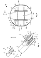
- a first embodiment of the contact preventer according to the invention is described hereafter with particular reference to Figures 1 and 2 .
- the contact preventer 5 comprises a protective housing 5'.
- the protective housing 5' comprises a receptacle 11 at its end pointing in the opposite direction to insertion direction E.
- An electrical conductor 13 can be introduced through the receptacle 11, with its end section 77 leading the way, into the protective housing 5' of the contact preventer 5.
- the end section 77 of this conductor (hereafter referred to as the second conductor 13) is also schematically depicted in Fig. 1 .
- the end section 77 of the conductor 13 substantially consists of a flat body 79 with an upper flat side 81 and a lower flat side 83.
- the end section 77 of the conductor 13 is configured in a fork shape with two prongs 84, 84' which point in insertion direction E and which can be arranged in a corresponding fork-shaped mating area 6 of the protective housing 5' such that the prongs 84, 84' correspond to a contacting slot 67, 67', via which an interior 69 of the contact preventer 5 is exposed to contact the prongs 84, 84', of the contact preventer 5.
- the contact preventer 5 features a protective housing 5' which has a fork-shaped mating area 6 with at least one contacting slot, and in the exemplary embodiment shown two contacting slots 67, 67', which run(s) parallel to insertion direction E and which outwardly expose(s) an interior 69 of the contact preventer 5 for contacting.
- the contacting slots 67, 67' and accordingly the contact preventer 5 are closed at the front end 71 pointing in insertion direction E, which increases safety because the end region 77 of the conductor 13 received in the contact preventer 5 cannot be touched by the user's fingers in insertion direction E.
- the mating area 6 has two prongs 184, 184'.
- the prongs 184, 184' form a recess 186 situated between them, which opens out in insertion direction E and which, in the embodiment shown, extends from its opening 188 in the opposite direction to insertion direction E.
- the recess 186 runs between the two contacting slots 67, 67'.
- the opening 188 points away from the receptacle 11.
- the at least one contacting slot and, in the embodiment shown the two contacting slots 67, 67' can form a guide 190 for inserting the contact preventer 5, which will be explored in greater detail below.
- the contact preventer 5 has two contacting slots 67, 67' which run parallel to insertion direction E.
- the contacting slot 67 exposes the interior 69 of the contact preventer 5.
- the contacting slot 67 extends up to a front end 71 of the contact preventer 5.
- the contacting slot 67 has a slot width 68 transverse to insertion direction E.
- a wall thickness 70 of the contact preventer 5 in the region of the contacting slot 67 is preferably selected such that a ratio of slot width 68 to wall thickness 70 is approximately 1.75.
- the contacting slot 67, 67' or the contact preventer 5 is closed at the front end 71.
- the contacting slot 67, 67' exposes the interior 69 of the contact preventer 5 for the first conductor 9.
- the press-on element 29 is arranged above or below the contacting slot 67.
- the longitudinal axis L of the press-on element 29, which axis runs parallel to effective direction W, is arranged centrally above the contacting slot 67.
- the longitudinal axis L runs perpendicular to insertion direction E.
- the contact preventer 5 On the side opposite the contacting slots 67, 67', the contact preventer 5 has two further contacting slots 67a, 67a'. In plug-in direction E and effective direction W, the slots 67a, 67a' are configured similarly to the contacting slots 67, 67'.
- the end section 77 of the second conductor 13 is formed by the flat body 79 of the cable shoe 17, the flat body 79 having an upper flat side 81 and a lower flat side 83.
- the lower flat side 83 is exposed by the contacting slots 67a, 67a' for contacting with the first conductor 9, and the upper flat side 81 is exposed by the slots 67, 67'.
- the flat sides 81 and 83 run perpendicular to effective direction W when the second conductor 13 is received with the contact preventer 5 on the press-on adapter 3.
- Fig. 3 depicts, in perspective, the contact preventer 5 according to the invention with a conductor 13 (not visible in Fig. 3 ) received therein.
- a conductor 13 not visible in Fig. 3
- two such identical conductors 13 with the contact preventers 5 are flange-mounted side-by-side on a housing wall 99.
- the flat body 79 configured as a cable shoe 17 is crimped together by a fork-shaped end section 77 in a crimped region 85 with the end of the contact preventer 5 which points in the opposite direction to insertion direction E.
- the contact preventer 5, the crimped region 85 and a cable isolation 78 protect the conductor 13 from being touched.
- FIG. 6 thereby shows the components of the described embodiment individually in an exploded view.
- the assembly 1 has a press-on adapter 3 with at least one press-on element 29 and a contact preventer 5.
- the press-on adapter 3 has a receptacle 7 for a first conductor 9 and the contact preventer 5 has a receptacle 11 for a second conductor 13.
- the first conductor 9 is depicted as a current rail 15 and the second conductor 13 is depicted as a cable shoe 17.
- both conductors 9 and 13 to be formed by current rails 15 or cable shoes 17.
- At least the end section 87 of the first conductor 9 is formed by a current rail 15.
- the end section 87 of the first conductor 9 is formed as a flat body 89 with an upper flat side 91 and a lower flat side 92.
- the flat sides 91, 92 of the first conductor 9 can be situated parallel to the flat sides 81 and 83 of the second conductor 13, if both conductors 9, 13 are arranged in the press-on adapter 3.
- the end section 87 of the first conductor 9 is configured as a fork head 98 with a notch 119 which runs from the front face, which points in the opposite direction to plug-in direction E, of the end section 87 in plug-in direction E and which can be configured with two prongs 120, 121.
- One contacting member 97 each is arranged on each of the prongs 120, 121.
- the contacting member 97 can be arranged on the upper flat side 91.
- contacting ribs 97a form the contacting members 97 which can be formed monolithically and which can be generated as legs 101 of a substantially U-shaped profile in the end section 87.
- the legs 101 rise substantially in insertion direction E out of the upper flat side 91.
- the contacting members 97 do not have to be configured monolithically with the end section 87, but rather also constitute separate elements which then have to be placed at the suitable point in the assembly.
- the press-on element 29 is configured to connect the first conductor 9 to the second conductor 13 in a frictionally engaged manner.
- the press-on element 29 can be formed as a screw 31. Turning the screw 31 about the screw longitudinal axis L leads to a movement of the screw 31 along, or in the opposite direction to, the effective direction W.
- the screw 31 has, as an actuation section 41, a screw head 35 which points in the opposite direction to effective direction W.
- the screw head 35 preferably has a screw head diameter 37 which is larger than a screw diameter 39. As a result, the screw 31 cannot be fully sunken.
- the screw head 35 constitutes the actuation section 41 of the press-on element 29.
- the actuation section 41 does not necessarily have to be formed as a screw head 35.
- the actuation section 41 can be formed at the end of the screw 31 pointing in the opposite direction to effective direction W, without going beyond the screw diameter 39.
- the actuation section 41 can be formed as a hexagonal socket aperture, for example.
- the press-on element 29 can exert a force at least in effective direction W, in order to connect the first conductor 9 to the second conductor 13 in a frictionally engaged manner.
- the press-on adapter 3 can have two press-on elements 29, 129.
- the second press-on element 129 can be formed as a nut 131.
- the nut 131 as a second press-on element 131, can be spaced apart from the first press-on element 29, the screw 31, in effective direction W and can be screwed onto the screw 31 with a positive fit.
- the first press-on element 29 and the second press-on element 129 can be coupled to one another such that the actuation of the one press-on element, the screw 31, also simultaneously brings about an actuation of the other press-on element 129, the nut 131.
- This coupling is distinguished by the fact that the screw head 35 and the nut 131 move towards one another in opposite directions to effective direction W and the expansion of the receptacle 7 is decreased as a result.
- the press-on adapter can form a receptacle 7 for the electrical conductors 9, 13.
- the receptacle 7 extends away in effective direction W of the press-on element 29.
- the receptacle 7 can extend from the first press-on element 29 to the second press-on element 7.
- stop members 51, 151 can be provided.
- the stop members 51, 151 are configured as securing rings 52, 152 which are attached to a defined point of the screw 31, the securing ring 152 being situated in effective direction W behind the nut 131, thus preventing a removal of the nut 33 from the screw 31.
- the securing ring 52 serves to retain a force distribution member 55, described in greater detail below, non-detachably on the screw 31.
- the press-on adapter 3 can further have a movable force distribution member 55, on which the press-on element 29 can exert an effect.
- the force distribution member 55 can distribute a normal force generated by the press-on element 29 in effective direction W, which is perpendicular to insertion direction E, onto a conductor 9, 13 arranged in the receptacle 7.
- the ends 57 of the force distribution member 55 are bent downwards in effective direction W and, in effective direction W, can align with a contacting slot 67, 67' or directed towards said contacting slot.
- the force distribution member 55 is configured in the shown embodiment as a press-on bracket.
- the press-on element 29 has the electrically isolated actuation section 43 which is preferably formed by an isolating cap 45.
- the isolating cap 45 can have the shape of a screw head in order to be actuated by a suitably configured tool.
- the isolating cap 45 is preferably formed from a plastic.
- the assembly 1 can have a housing 47 isolated at least from the press-on adapter 3.
- the housing 47 can have an aperture 49 through which the electrically isolated actuation section 43 of the press-on element 29 can protrude outwardly.
- the aperture 49 can be smaller than a stop member (not shown) of the electrically isolated actuation section 43.
- the stop member can be formed as a circumferential ring or as a screw head and form a stop for the electrically isolated actuation section 43 in the opposite direction to effective direction W. The stop member therefore prevents the press-on adapter 29 from being completely released from the press-on adapter 3.
- the housing 47 has (as can clearly be seen in Fig. 4 ) a collar 53 which projects in a direction opposite to insertion direction E and which exposes the inner space 48 of the housing 47, in particular the receptacle 7 of the press-on adapter 3 for the contact preventer 5.
- the collar 53 can prevent a finger, a tool or another part from getting into the housing 47 and can produce an electrical contact with one of the elements situated in the housing 47.
- a contacting slot 67, 67' can configure a guide 190 for the straight-lined insertion of the contact preventer 5 along insertion direction E.
- the contacting slot 67 or 67' is provided with guide rails (or also guide webs) 191.
- the guide rails 191 are configured by the walls 192, which limit the contacting slot 67, 67' transverse to insertion direction E and transverse to effective direction W. These walls 192 and thus the guide rails 191 formed therefrom run in insertion direction E.
- a guide groove 193 is formed between the guide rails 191 of a contacting slot 67, 67'.
- the collar 53 of the housing 47 is equipped with counter guides 196 or, in the shown exemplary embodiment, with counter guide rails 194, between which a counter guide groove 195 is configured, which correspond to the guide rails 191 or the guide groove 193 of the contact preventer 5.
- a counter guide rail 194 engages in a guide groove 193, and in a similar manner a guide rail 191 engages in the guide grooves 195. In this manner, a directed insertion of the contact preventer 5 into the housing 47 is facilitated.
- the housing 47 can further have a finger protection web 200 which protrudes in the region of the actuation section 41 from the wall 201 of the housing 47 which points in the opposite direction to insertion direction E.
- the finger protection web 200 can prevent fingers etc. from getting caught in the region of the press-on element 29 when actuating the press-on element 29.
- the assembly 1 can further have an actuation safeguard 210 which can be transferred from a closed position (see Fig. 5 ) into an open position (see Fig. 10 ).
- the actuation safeguard 210 prohibits an actuation of the press-on element 29, whereas the actuation safeguard 210 in the open position exposes the actuation of the press-on element 29.
- the actuation safeguard 210 is movable relative to the press-on element 29.
- the actuation safeguard 210 is displaceably arranged on the side 202 of the housing 47 pointing in the opposite direction to effective direction W and can be moved in, or in the opposite direction to, insertion direction E.
- the open position see Fig.
- the actuation safeguard 210 is situated above the guide web 200 which can thus assume a double function, namely a finger protection function, on the one hand, and a guide and receptacle for the actuation safeguard 210 in its open and closed positions respectively.
- a member 211 of an interlock can constitute the actuation safeguard 210, which is advantageous insofar as this interlock member 211 must, in any case, be separated from its counter-member 212 in order to focus the security system, a High-Volt Interlock System.
- the actuation safeguard 210 In the closed position, the actuation safeguard 210, the interlock member 211 in the embodiment shown, is arranged such that the actuation section 41 of the press-on element 29 is not accessible.
- the interlock member can be situated so close to the screw head 35 or its isolating cap 45 that it becomes impossible to grip, not to mention turn, the screw head with a tool, for example a socket wrench.
- the actuation safeguard 210 then moves so far away from the press-on element 29 that it can be actuated, i.e. the screw 31 can be turned.
- the assembly 1 according to the invention can further have an actuation portal 220 which indicates the direction from which the actuation section 41 is accessible.
- the actuation section 41 is bordered on the side of the housing 47 which points in the opposite direction to effective direction W.
- a collar 221 is formed rising from the side 202 of the housing 47 pointing in the opposite direction to effective direction W.
- the collar 221 encloses large parts of the actuation section 41, i.e. the screw head 45 or its isolated actuation section 43.
- the collar can enclose at least half, and in the embodiment shown almost two-thirds, of the actuation section 21.
- the collar 221 is only open at the point at which the interlock system is located with the interlock member 211 and its counter-member 212.
- the collar 221 completely encloses the actuation section 41.
- the collar 221 ensures that the actuation section 41 cannot be reached laterally, i.e. transverse to effective direction W.
- no open-end wrench for example, can be applied to the screw head 35.
- a socket wrench can only be placed onto the screw head 35 or its isolating cap 45 in effective direction W, in order to actuate the press-on element 29.
- the first conductor 9 is arranged in the inner space 48 of the housing 47 so that the screw 31 penetrates the notch 119 in effective direction W.
- the contact preventer 5 is introduced, with its plugging area leading the way through the collar apertures 54 into the inner space 48 until the screw 31 also penetrates the recess 186 of the contact preventer.
- the first conductor 9 is thereby arranged in effective direction W beneath the second conductor 13.
- the press-on element 29 is preferably actuated such that at least one of the two conductors 9 and 13 or both can be smoothly inserted into the receptacle 7. Only when both the first conductor 9 and the second conductor 13 with the contact preventer 5 in the receptacle 7 are arranged on the press-on adapter 3 is the press-on element 29 actuated, so that a normal force is exerted along the effective direction W on both conductors 9 and 13. The press-on element 29 is therefore actuated separately.
- the screw 31 moves in effective direction W.
- the nut moves in the opposite direction to effective direction W.
- the spatial expansion of the receptacle 7 in effective direction W is reduced and the first conductor 9 situated in the receptacle 9 can be pressed onto the second conductor 13 situated in the receptacle 7 and, as a result, the two conductors are connected to one another in a frictionally engaged manner and are electrically connected.
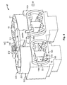
- Fig. 8 a cross-section of an assembly 1 is shown in which the first conductor 9 and the second conductor 13 are arranged in the receptacle 7 of the press-on adapter 3.
- the screw head 35 moves downwards in effective direction W and, in the process, presses on the force distribution member 55 which passes the pressing force into its downwardly bent ends 57.
- the ends 57 are arranged in effective direction W above the contacting slots 67, 67', the ends 57 can penetrate into the interior 69 of the contact preventer 5 via the slots 67, 67' and press the prongs 84, 84' located in the prongs 184, 184' of the contact preventer 5 in the end section 77 of the second conductor 13 in effective direction W and, thus, in the direction of the second conductor 13.
- the second press-on element 129 moves in the opposite direction to effective direction W and transmits a press-on force onto the lower flat side 92 in the end section 87 of the first conductor 9.
- the forces are transmitted through the body of the end section 87 into the contacting members 97, namely the leg 101, which protrude out of the upper flat side 91 of the first conductor 9 in effective direction W.
- the contacting members 97/legs 101 can align with the contacting slots 67a, 67a' in effective direction W, penetrate into these and in this manner be connected in a frictionally engaged manner with the prongs 84, 84' in the end section 77 of the second conductor 13.
- a further force distribution member 155 which can transmit the force from the nut 131 to the first conductor 9, so that it is distributed uniformly and over a larger surface without unintentionally deforming this conductor 9 under the force exerted by the press-on element 129.
- the second force distribution member 155 can also be omitted and the nut 131 can be arranged, in a force-transmitting manner, directly on the conductor 9 allocated to it.
- the insert nut 131 is then pressed directly into the current rail 15, as is the case in the second embodiment of the assembly 1 according to the invention.
- the second embodiment of the assembly 1 according to the invention corresponds to the first embodiment, which is why only the differences of the second embodiment are shown in the sectional depiction according to Fig. 11 .
- a third embodiment is shown in Figs. 12 to 14 .
- the third embodiment corresponds to the first embodiment.
- the only difference from the first embodiment is that the prongs 120, 121 in the end section 87 of the first conductor directly form the contacting members 97.
- the legs 101 can be omitted in the third embodiment. This facilitates the manufacture of the end section 87 of the first conductor which can be constructed from a current rail 15 (from a cable shoe 17) which has a notch which points in the opposite direction to plug-in direction E.
- FIG. 14 and 15 A second embodiment of a contact preventer 5 according to the invention is shown in Figs. 14 and 15 .
- the contact preventer according to the second embodiment corresponds largely to the contact preventer 5 of the first embodiment, such that hereafter only the differences of the second embodiment of the contact preventer 5 compared to those of the first embodiment depicted in Figs. 1 and 2 are cited.
- the contacting slot 67, 67' is closed at the front end 71 pointing in insertion direction E.
- the closure wall 171 at the front end 71 of the contacting slot 67, 67' or contact preventer 5 is extended upwards or downwards in or in the opposite direction to effective direction W to such an extent that the closure wall 171, in the projection in the opposite direction to insertion direction E, completely obscures the contacting slots 67, 67', etc.
- the upper rim 172 of the closure wall 171 aligns with the rim of the lateral wall 192 in the opposite direction to effective direction W.
- the lower rim 173 of the closure wall 171 likewise aligns with the lower rim of the lateral wall 172 in effective direction W.
- An advantage of the contact preventer 5 of the second embodiment is that the contacting of a conductor 13 received in the contact preventer 5 can then only take place if the contact preventer 5 has been completely introduced into the housing 47 in insertion direction E. If the contact preventer 5 is not yet fully introduced in insertion direction E, the closure wall 171 could block a contacting of the prongs 84, 84' of the second conductor 13 with the end section 87 of the first conductor. The blocking could be realised such that the ends 57 of the force distribution member 55 or the contacting ribs 97a or legs 101 of the contacting member 97, viewed in effective direction W, overlap the upper rim 172 of the closure wall 171.
- the length 168 of the contacting slot is of a size such that it substantially corresponds to the length of the lower ends 57 or the length of the contacting rib 197a or is only marginally shorter.
- other blocking means can also be provided for the assembly which prohibit the press-on adapter 3 from accessing the interior 69 of the contact preventer 5.
- an access block could cover the contacting slot, as long as the contact preventer 5 is not yet positioned properly for the contacting.
Landscapes
- Details Of Connecting Devices For Male And Female Coupling (AREA)
- Connector Housings Or Holding Contact Members (AREA)
- Connections By Means Of Piercing Elements, Nuts, Or Screws (AREA)
Abstract
Description
- The invention relates to an assembly for connecting a first electrical conductor to a second electrical conductor. The invention further relates to a contact preventer for an electrical conductor for connecting the conductor received in the contact preventer in the insertion direction to another conductor, with a protective housing which comprises a receptacle for the conductor. In particular, the invention relates to an assembly for connecting two electrical conductors, of which at least one electrical conductor is a current rail or a cable shoe.
- Assemblies are known for connecting electrical conductors. Two conductors are frequently connected to one another by plugging them together. However, in the region of high voltages and/or strengths of currents, plug connections are frequently impracticable because in this case solid conductors are frequently used, with which plug connectors can be produced only incompletely. In particular, screw connections are used to connect at least one current rail or one cable shoe to another conductor. For example, a cable shoe with an aperture for a screw can be screwed onto a current rail or a second cable shoe. In this case, either a screw protrudes through a hole into the cable shoe and is screwed with an insert nut in the current rail, or the screw protrudes through both parts and is equipped with a nut so that the current rail and the cable shoe are clamped between the screw head and the nut.
- Similar connections are used if two current rails or two cable shoes are intended to be connected to one another. This connection method is time-consuming and has several disadvantages. For example, the screw and/or the nut can be lost when connecting or releasing the conductors. A further known problem can be that a screw cannot be completely unscrewed from both conductors. In this case, it can be that, if the screw has arrived at the end of a maximum path, it fully penetrates one of the two conductors and at the same time is still partly arranged in the other conductor. The releasing of the two conductors from one another is consequently hindered or even impossible. A further known disadvantage is that at least one of the two conductors is frequently only insufficiently or not at all protected from touching and therefore can endanger the safety of a person handling at least one of the conductors.
- The object of the invention is therefore to make available a contact preventer for electrical conductors and an assembly for connecting a first electrical conductor to a second electrical conductor, by means of which the electrical conductors are repeatedly able to be connected to one another or released from one another smoothly, and with the danger from electric shock being decreased compared to known connection assemblies.
- According to the invention, the object is achieved by a contact preventer, in which the protective housing has a fork-shaped mating area with at least one contacting slot which runs parallel to the insertion direction and which exposes an interior of the contact preventer to the outside for contacting. The object is further achieved according to the invention by an assembly for connecting a first electrical conductor to a second electrical conductor, with a press-on adapter, which has at least one externally actuable press-on element, and with a housing-like contact preventer with a receptacle for the second conductor, the contact preventer being configured according to the invention.
- The solution according to the invention achieves the object in a particularly advantageous manner. The contact preventer can effectively prevent a person or another part from unintentionally touching a (second) conductor received in the contact preventer. The fork-shaped mating area can receive a part of the press-on adapter, as a result of which the contact preventer according to the invention can be arranged on the press-on adapter when moved along the insertion direction. By way of example, the mating area can be arranged in a receptacle of the press-on adapter. The contacting slot can expose a received conductor to the outside so that it can be connected to a first conductor. Through the externally actuable press-on element, the first and the second conductors can be pressed onto one another by the press-on adapter, such that an electrical connection can be produced between the two conductors. The two conductors can thus be smoothly connected to one another or released from one another repeatedly. The contacting slot can expose the interior of the contact preventer in particular towards the receptacle for the first conductor. A contacting of the two conductors can then take place in the region of the contacting slot.
- The solution according to the invention can be further improved by way of various, individually advantageous configurations respectively which can be combined with one another as desired. These configurations and the advantages connected thereto shall be explored hereafter.
- According to an advantageous configuration, the contacting slot can be closed at a front end which points in the insertion direction. The contact preventer as a whole can be closed at its front end which points in the insertion direction. As a result of this structurally simple measure, the safety of the contact preventer can be increased.
- According to a further configuration, the mating area can have at least two prongs and a recess situated between them. The recess can open out in the insertion direction. The recess can extend from its opening in a direction opposite to the insertion direction. The opening in the fork shape makes it possible, when arranging the contact preventer on the press-on adapter, for regions of the adapter or other members of the assembly to be able to penetrate through the opening into the recess in the insertion direction and to be arranged between the prongs.
- In a further configuration, the recess can run between two contacting slots. By way of example, this can be achieved by each of the at least two prongs being provided with a contacting slot. In this configuration, a fork head-shaped mating area is achieved, of which the prongs equipped with contacting slots are arranged in direct proximity to the recess situated between them, which facilitates arranging on the press-on adapter. This achieves a very compact design and permits the arrangement of the contacting slots in direct proximity to the press-on adapter.
- The at least one contacting slot is preferably configured such that a finger cannot reach the interior of the contact preventer. The at least one contacting slot is preferably configured such that a standardised test finger, for example a test finger from the German Association of Engineers, cannot contact a conductor received in the contact preventer. The at least one contacting slot preferably has a slot width of approximately 2, preferably approximately 3 to approximately 4 mm, particularly preferably approximately 3.5 mm. A wall thickness of the contact preventer alongside the contacting slot is preferably approximately 1.5 to approximately 2.5 mm thick. The wall thickness depends on the slot width. A larger slot width makes a larger wall thickness necessary in order to prevent the penetration of a finger into the contacting slot up to the interior of the contact preventer. In order to guarantee an effective contact preventer with a slot width of approximately 3.5 mm, the wall thickness of the contact preventer is preferably at least approximately 2 mm. A ratio of slot width to wall thickness is preferably 1.75.
- In order to provide sufficient contact surface for a given width of a second conductor, and at the same time to guarantee effective contact prevention, the contacting slot can be narrower than one-third of an inner width of the contact preventer. The inner width of the contact preventer preferably approximately corresponds to the width of a conductor which is intended to be received in the contact preventer. If the contact preventer has a single contacting slot on one prong, the contacting slot can be arranged centrally, i.e. with the same spacing from the sides of the prong.
- According to a further embodiment, an aperture of the receptacle can point in the opposing direction to the opening of the recess. The electrical conductor is introduced into the contact preventer through the receptacle's aperture. The conductor can be inserted in the insertion direction and the contact members or regions can be introduced up to the end of the contact preventer pointing in the insertion direction. This also prevents the electrical conductor from unintentionally falling out of the receptacle of the contact preventer when connecting to another conductor in the insertion direction.
- According to a further embodiment, the at least one contacting slot can form a guide for the contact preventer to be inserted in a straight line. Thus, a wall of at least one contacting slot can have a guide rail and/or a guide groove. The guide, guide rail or guide groove preferably points in the insertion direction and can interact with a corresponding counter guide member of the assembly, for example a counter-member, such as a counter-rail or counter-groove on the press-on adapter and/or a housing of the assembly.
- According to a further embodiment, a fork-shaped end section of the conductor can be arranged in the mating area of the contact preventer. This unit made up of contact preventer and conductor received therein can, without the danger of electric shock, be connected to another conductor even by staff who are not explicitly trained for this, in particular within the framework of the assembly according to the invention, the various configurations of which will be explored in greater detail below.
- According to one configuration, the press-on element can be configured for connecting, in a separately actuable, frictionally engaged manner, a first conductor arranged on the press-on adapter and a second conductor received in the contact preventer. Two conductors can thus be held against one another in the press-on adapter by a frictionally engaged connection. At the same time, they are connected to one another in an electrically conductive manner via the frictionally engaged connection. The press-on element can be actuated independently of the introduction of the conductors into the region of action of the press-on adapter. By way of example, the contact preventer can first be arranged with the second conductor on the press-on adapter. For this purpose, a part of the press-on adapter, such as a region of the press-on element, can be arranged in the mating area, preferably in its recess or can be inserted into the press-on adapter. The press-on element can be actuated subsequently. A particularly good connection between the first and the second conductors can be obtained in that a normal force acting perpendicular to the insertion direction can be generated between the first and the second conductors by the press-on element.
- According to a further advantageous configuration, the assembly can have a force distribution member onto which the press-on element can exert an effect. The force distribution member can redirect the normal force generated by the press-on element to the desired location and/or distribute it onto a larger surface so that a surface pressure of the press-on element onto one of the two conductors can be decreased. The force distribution member can be configured in a stirrup shape and can have several force zones which are each allocated to a contacting slot. The press-on element or force distribution member can, when the contact preventer is inserted, be arranged over the at least one contacting slot. As a result, the press-on element can press the first conductor in the direction of the contacting slot, either directly or via the force distribution member. A press-on adapter's receptacle for the conductors is preferably arranged between the at least one contacting slot and the press-on element. An effective direction of the press-on element can be directed onto the contacting slot. In this manner, a normal force acting perpendicular to the insertion direction can be generated between the first and the second conductors.
- According to a further embodiment, the assembly according to the invention can have a blocking member which prohibits the press-on adapter from accessing the interior of the contact preventer via a contacting slot. The blocking member can prevent the press-on adapter's conductor, which is received in the adapter and allocated to the contacting slot, from being connected to the corresponding other conductor. In particular, the blocking can occur if the contact preventer is not properly placed on the press-on adapter or housing of the assembly. According to one embodiment, a wall of the contact preventer running perpendicular to the insertion direction can form the blocking member. By way of example, a closure wall which points in the insertion direction and which closes a contacting slot can form the blocking member. In this case, the closure wall can limit the length of the contacting slot. This makes possible an embodiment in which the region of the press-on element or of the first electrical conductor which is to be retracted into the contacting slot is only arranged above the at least one contacting slot and is aligned with said contacting slot, if the contact preventer is properly arranged on the press-on adapter and/or on the housing of the assembly.
- In order to prevent losing the press-on element, the press-on element can be non-detachably retained on the press-on adapter and/or a housing of the assembly. The press-on element can hereby be movably retained on the press-on adapter so that it is well able to be actuated despite being non-detachable. The force distribution member can also be non-detachably retained on the press-on adapter, preferably on the press-on element. By way of example, the press-on element can penetrate the force distribution member at at least one location in order to achieve a non-detachable mounting.
- According to one embodiment, the press-on adapter can have two press-on elements spaced apart from one another. The press-on elements spaced apart from one another can, in a structurally simple manner, form between them a receptacle of the press-on adapter for electrical conductors. When one or both press-on elements are actuated, the conductors can be clamped in the receptacle between these press-on elements. The directions of action of the two press-on elements are preferably directed towards one another. The two press-on elements spaced apart from one another can be coupled, such that the actuation of the one press-on element also simultaneously triggers the actuation of the other press-on element, preferably in the opposite direction of action.
- A particularly simply constructed press-on element can be obtained in that the press-on element is formed by a screw and/or a nut. The screw can be arranged such that a screw longitudinal axis is arranged perpendicular to the insertion direction. The screw can, for example, be guided by a thread which is formed directly in the press-on adapter or by a separate nut. The nut can likewise be part of the press-on adapter and form a further press-on element. A receptacle, in which the electrical conductors can be pressed against one another, can thus be formed between the press-on elements formed by the nut and the screw as another press-on element. A non-detachability of the screw and/or the nut can be provided in that the screw can be moved against the effective direction only up to a position fixed by a stop member (for example a securing ring). In this case, the position can be determined such that the press-on element(s) completely expose at least one of the conductors such that this conductor can be separated from the other conductor. In a configuration with two press-on elements, the one press-on element can be non-detachably retained on the second press-on element. For example, a nut screwed onto the thread of a screw can be non-detachably retained by a securing ring or a locking cap.
- In order to increase the safety when actuating the at least one press-on element, the at least one press-on element can have an actuation section, which is electrically isolated relative to the rest of the press-on element, for actuating the press-on element. If the press-on element is formed by a screw, for example, then the actuation section electrically isolated relative to the rest of the press-on element can be formed by an isolating cap on the screw head.
- According to a further advantageous configuration, the assembly can have a housing which is electrically isolated at least from the press-on adapter. The actuation section at least of a press-on element can be arranged on the housing in an externally accessible manner. In particular the housing can protect conductors arranged on the press-on adapter from external contact. The housing can have an aperture towards an operating side which exposes the press-on element for the contact preventer to the outside. In order to prevent an unintentional penetration of a finger or of a tool into the aperture, the aperture can be enclosed by a protruding collar.
- In addition to the electrically isolated housing, the assembly can have a screen which encloses the assembly in order to electromagnetically screen the assembly towards the outside. In addition, the assembly can have a security system or be connected to a security system. A security system can be formed by a High-Voltage Interlock System (HVIL), for example. As a result of this, it can be ensured that conductors arranged in the press-on adapter no longer carry current before the press-on element is actuated or at least one of the conductors is handled.
- According to a further embodiment, the assembly can have an actuation safeguard. The actuation safeguard can be transferred from a closed position, in which it prevents the actuation of the press-on element, into an open position, in which it exposes the actuation of the press-on element. The actuation safeguard increases the safety of the assembly according to the invention, because the first and the second conductors can be pressed against one another and electrically contacted to one another only when the actuation safeguard exposes the actuation of the press-on element. In one embodiment, the actuation safeguard can be arranged displaceably relative to the press-on element, for example supported on the housing of the assembly in order to be simply transferred from its closed position into its open position.
- A particularly structurally simple embodiment can envisage that an interlock forms the actuation safeguard. For example, in the actuation safeguard's closed position, the interlock can prohibit a tool from accessing the actuation section of the press-on element. Thus, if the actuation section is configured as a screw head for example, the actuation safeguard could, in the closed position, cover the screw head, prevent it from turning or at least preclude the application of a tool required for its actuation.
- The actuation of the interlock can not only activate the security system, but at the same time the actuation safeguard can be transferred from its closed position into the open position.
- According to a further configuration, the assembly can have an actuation portal which indicates the direction from which the actuation section is accessible. For example, the actuation portal can border the actuation section such that the actuation section is not accessible from the sides of the bordering (i.e. laterally), but rather only from a defined direction (e.g. from above) with an actuation tool. According to one configuration, the electrically isolated housing can have an outwardly projecting collar which borders the actuation section of the at least one press-on element at least in sections. If the actuation section of the press-on element is configured as the head of a screw, for example, the collar prevents the use of an open-end wrench, because, due to the bordering by the collar, it cannot be applied laterally. In this manner, this makes it necessary to use a socket wrench placed on from above in order to actuate the press-on element.
- In order to obtain as large a contact surface as possible and to facilitate the insertion of the contact preventer into the press-on adapter, the at least one contacting slot can continuously extend up to the front end of the contact preventer.
- According to a further advantageous configuration, the assembly comprises a first conductor received in the press-on adapter's receptacle and a second conductor received in the receptacle of the contact preventer, the first conductor being formed by a current rail at least in an end section arranged in the receptacle and the second conductor being formed by a cable shoe at least in an end section arranged in the contact preventer, or vice versa. The assembly according to the invention can therefore be used particularly advantageously to connect a cable shoe to a current rail. In this case, the press-on adapter can be arranged both on sides of the current rail or on sides of the cable shoe. The other conductor in each case is then the second conductor according to the invention, which can be arranged in the contact preventer and which can be inserted into the press-on adapter. The end sections of the first and of the second conductor can also be formed by cable shoes or by current rails.
- The end section of the first conductor can form a fork head. The prongs of the fork head of the first conductor can be simply allocated to the fork-shaped plugging slot, for example the prongs of the first conductor can be overlaid with prongs of the first plugging slot. The overlaying can preferably take place in the direction in which the press-on element transmits a force when actuated.
- According to a further advantageous configuration, when the contact preventer is inserted, at least one contacting member connected to the first conductor in the at least one contacting slot is held by the press-on element against the second conductor in a frictionally engaged manner. The at least one contacting member preferably produces the electrical connection between the first and the second conductors. In a particularly simple configuration, the at least one contacting member is formed monolithically with the end section of the first conductor. The at least one contacting member can be configured as a contacting rib which protrudes from the first conductor. The first conductor can then be pressed towards the second conductor such that the contacting rib is pressed against the second conductor through the contacting slot.
- According to a further advantageous configuration, the first conductor can have an end section which in a cross-section transverse to the insertion direction has a U-shaped profile, and wherein the legs of the U-shaped profile can be pressed onto the second conductor under the effect of the press-on element through at least two contacting slots. The legs of the U-shaped profile then constitute two contacting members. By means of this variant it is possible to achieve a more compact design compared to the assembly of two flat bodies which are perpendicular to one another. In addition, a contacting of the two conductors takes place at at least two positions, as a result of which a particularly good electrical contact is achieved between the two conductors. In this case, the legs can be formed such that they are perpendicular to a surface of the second conductor at least in the region of an abutment point between the first and second conductors. In this case, the second conductor is preferably formed at least in the end section by a flat body.
- Hereinafter, the invention is explained in greater detail, by way of example, using advantageous embodiments with reference to the drawings. The combinations of features depicted by the embodiments by way of example can be supplemented accordingly by additional features for a particular application in accordance with the comments above. It is additionally possible, also in accordance with the comments above, for individual features to be omitted in the described embodiments, if the effect of said feature is not important in a specific application.
- In the drawings, the same reference numerals are always used for elements with the same function and/or the same structure.
- Fig. 1
- shows a perspective depiction of an embodiment of a contact preventer according to the invention together with an embodiment of a conductor which can be received therein;
- Fig. 2
- shows a top view of the contact preventer from
Fig. 1 , viewed in the opposite direction to the plug-in direction; - Fig. 3
- shows a perspective depiction of an embodiment of a contact preventer according to
Fig. 1 which is connected to an electrical conductor; - Fig. 4
- shows a perspective depiction of the housing of the assembly of the first embodiment viewed in the plug-in direction;
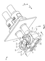
- Fig. 5
- shows a perspective depiction of a first embodiment of an assembly according to the invention in the pushed-together state;
- Fig. 6
- shows an exploded view of the components of the first embodiment;
- Fig. 7
- shows an enlargement of the end section of the first electrical conductor of the first embodiment;
- Fig. 8
- shows a cross-section through the first embodiment along the section plane A-A;
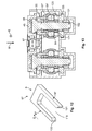
- Fig. 9
- shows a longitudinal section of the first embodiment along the section plane B-B;
- Fig, 10
- shows a perspective depiction of the first embodiment corresponding to the depiction from
Fig. 5 , in which the actuation safeguard is in the opened position and the interlock region is depicted in section; - Fig. 11
- shows a cross-section, corresponding to the cross-section of
Fig. 8 , of a second embodiment of an assembly according to the invention; - Fig. 12
- shows an end section of a first conductor according to a third embodiment of an assembly according to the invention;
- Fig. 13
- shows a cross-section, corresponding to the cross-section of
Fig. 8 , of the third embodiment; and - Fig. 14
- shows a perspective depiction of a second embodiment of a contact preventer according to the invention; and
- Fig. 15
- shows a longitudinal section through the second embodiment of the contact preventer along the section plane C-C.
- A first embodiment of the contact preventer according to the invention is described hereafter with particular reference to
Figures 1 and 2 . - The
contact preventer 5 comprises a protective housing 5'. The protective housing 5' comprises areceptacle 11 at its end pointing in the opposite direction to insertion direction E. Anelectrical conductor 13 can be introduced through thereceptacle 11, with itsend section 77 leading the way, into the protective housing 5' of thecontact preventer 5. Theend section 77 of this conductor (hereafter referred to as the second conductor 13) is also schematically depicted inFig. 1 . - The
end section 77 of theconductor 13 substantially consists of a flat body 79 with an upperflat side 81 and a lowerflat side 83. Theend section 77 of theconductor 13 is configured in a fork shape with twoprongs 84, 84' which point in insertion direction E and which can be arranged in a corresponding fork-shapedmating area 6 of the protective housing 5' such that theprongs 84, 84' correspond to a contactingslot 67, 67', via which an interior 69 of thecontact preventer 5 is exposed to contact theprongs 84, 84', of thecontact preventer 5. - The
contact preventer 5 features a protective housing 5' which has a fork-shapedmating area 6 with at least one contacting slot, and in the exemplary embodiment shown two contactingslots 67, 67', which run(s) parallel to insertion direction E and which outwardly expose(s) an interior 69 of thecontact preventer 5 for contacting. - The contacting
slots 67, 67' and accordingly thecontact preventer 5 are closed at thefront end 71 pointing in insertion direction E, which increases safety because theend region 77 of theconductor 13 received in thecontact preventer 5 cannot be touched by the user's fingers in insertion direction E. - In the embodiment shown, the
mating area 6 has twoprongs 184, 184'. Theprongs 184, 184' form arecess 186 situated between them, which opens out in insertion direction E and which, in the embodiment shown, extends from itsopening 188 in the opposite direction to insertion direction E. In the embodiment shown, therecess 186 runs between the two contactingslots 67, 67'. In the embodiment shown, theopening 188 points away from thereceptacle 11. - The at least one contacting slot and, in the embodiment shown the two contacting
slots 67, 67' can form aguide 190 for inserting thecontact preventer 5, which will be explored in greater detail below. - In the embodiment shown, the
contact preventer 5 has two contactingslots 67, 67' which run parallel to insertion direction E.The contacting slot 67 exposes the interior 69 of thecontact preventer 5. The contactingslot 67 extends up to afront end 71 of thecontact preventer 5. The contactingslot 67 has aslot width 68 transverse to insertion direction E.A wall thickness 70 of thecontact preventer 5 in the region of the contactingslot 67 is preferably selected such that a ratio ofslot width 68 to wallthickness 70 is approximately 1.75. The contactingslot 67, 67' or thecontact preventer 5 is closed at thefront end 71. When thecontact preventer 5 is received in the interior 54, the contactingslot 67, 67' exposes the interior 69 of thecontact preventer 5 for thefirst conductor 9. In doing so, the press-onelement 29 is arranged above or below the contactingslot 67. In the cross-section transverse to insertion direction (Fig. 8 ), the longitudinal axis L of the press-onelement 29, which axis runs parallel to effective direction W, is arranged centrally above the contactingslot 67. The longitudinal axis L runs perpendicular to insertion direction E. - On the side opposite the contacting
slots 67, 67', thecontact preventer 5 has two further contactingslots slots slots 67, 67'. - As already mentioned, the
end section 77 of thesecond conductor 13 is formed by the flat body 79 of thecable shoe 17, the flat body 79 having an upperflat side 81 and a lowerflat side 83. The lowerflat side 83 is exposed by the contactingslots first conductor 9, and the upperflat side 81 is exposed by theslots 67, 67'. Theflat sides second conductor 13 is received with thecontact preventer 5 on the press-onadapter 3. -
Fig. 3 depicts, in perspective, thecontact preventer 5 according to the invention with a conductor 13 (not visible inFig. 3 ) received therein. In the embodiment shown, two suchidentical conductors 13 with thecontact preventers 5 are flange-mounted side-by-side on ahousing wall 99. In this case, in the embodiment shown, the flat body 79 configured as acable shoe 17 is crimped together by a fork-shapedend section 77 in a crimpedregion 85 with the end of thecontact preventer 5 which points in the opposite direction to insertion direction E. Thecontact preventer 5, the crimpedregion 85 and acable isolation 78 protect theconductor 13 from being touched. - A first advantageous embodiment of the assembly according to the invention is described below with reference to
Figs. 4 to 10 .Fig. 6 thereby shows the components of the described embodiment individually in an exploded view. - The
assembly 1 has a press-onadapter 3 with at least one press-onelement 29 and acontact preventer 5. The press-onadapter 3 has a receptacle 7 for afirst conductor 9 and thecontact preventer 5 has areceptacle 11 for asecond conductor 13. Merely by way of example, thefirst conductor 9 is depicted as acurrent rail 15 and thesecond conductor 13 is depicted as acable shoe 17. Alternatively, it is possible for thefirst conductor 9 to be formed by acable shoe 17 and for thesecond conductor 13 to be formed by acurrent rail 15. It is also possible for bothconductors current rails 15 or cable shoes 17. - At least the
end section 87 of thefirst conductor 9 is formed by acurrent rail 15. Theend section 87 of thefirst conductor 9 is formed as aflat body 89 with an upperflat side 91 and a lowerflat side 92. Theflat sides first conductor 9 can be situated parallel to theflat sides second conductor 13, if bothconductors adapter 3. - The
end section 87 of thefirst conductor 9 is configured as a fork head 98 with anotch 119 which runs from the front face, which points in the opposite direction to plug-in direction E, of theend section 87 in plug-in direction E and which can be configured with twoprongs member 97 each is arranged on each of theprongs member 97 can be arranged on the upperflat side 91. In the embodiment shown, contactingribs 97a form the contactingmembers 97 which can be formed monolithically and which can be generated aslegs 101 of a substantially U-shaped profile in theend section 87. Thelegs 101 rise substantially in insertion direction E out of the upperflat side 91. However, the contactingmembers 97 do not have to be configured monolithically with theend section 87, but rather also constitute separate elements which then have to be placed at the suitable point in the assembly. - For this purpose, the press-on
element 29 is configured to connect thefirst conductor 9 to thesecond conductor 13 in a frictionally engaged manner. The press-onelement 29 can be formed as ascrew 31. Turning thescrew 31 about the screw longitudinal axis L leads to a movement of thescrew 31 along, or in the opposite direction to, the effective direction W. Thescrew 31 has, as anactuation section 41, ascrew head 35 which points in the opposite direction to effective direction W. Thescrew head 35 preferably has ascrew head diameter 37 which is larger than ascrew diameter 39. As a result, thescrew 31 cannot be fully sunken. Thescrew head 35 constitutes theactuation section 41 of the press-onelement 29. Theactuation section 41 does not necessarily have to be formed as ascrew head 35. If thescrew 31 is designed as a set screw, for example, theactuation section 41 can be formed at the end of thescrew 31 pointing in the opposite direction to effective direction W, without going beyond thescrew diameter 39. Theactuation section 41 can be formed as a hexagonal socket aperture, for example. The press-onelement 29 can exert a force at least in effective direction W, in order to connect thefirst conductor 9 to thesecond conductor 13 in a frictionally engaged manner. - The press-on
adapter 3 can have two press-onelements element 129 can be formed as anut 131. Thenut 131, as a second press-onelement 131, can be spaced apart from the first press-onelement 29, thescrew 31, in effective direction W and can be screwed onto thescrew 31 with a positive fit. In this manner, the first press-onelement 29 and the second press-onelement 129 can be coupled to one another such that the actuation of the one press-on element, thescrew 31, also simultaneously brings about an actuation of the other press-onelement 129, thenut 131. This coupling is distinguished by the fact that thescrew head 35 and thenut 131 move towards one another in opposite directions to effective direction W and the expansion of the receptacle 7 is decreased as a result. - The press-on adapter can form a receptacle 7 for the
electrical conductors element 29. The receptacle 7 can extend from the first press-onelement 29 to the second press-on element 7. - In order to arrange the press-on
elements force distribution member 55 non-detachably on the press-onadapter 3, stopmembers 51, 151 can be provided. In the embodiment shown, thestop members 51, 151 are configured as securingrings screw 31, the securingring 152 being situated in effective direction W behind thenut 131, thus preventing a removal of the nut 33 from thescrew 31. The securingring 52 serves to retain aforce distribution member 55, described in greater detail below, non-detachably on thescrew 31. - The press-on
adapter 3 can further have a movableforce distribution member 55, on which the press-onelement 29 can exert an effect. Theforce distribution member 55 can distribute a normal force generated by the press-onelement 29 in effective direction W, which is perpendicular to insertion direction E, onto aconductor force distribution member 55 are bent downwards in effective direction W and, in effective direction W, can align with a contactingslot 67, 67' or directed towards said contacting slot. Theforce distribution member 55 is configured in the shown embodiment as a press-on bracket. - To electrically isolate the press-on
element 29 outside of the press-onadapter 3, the press-onelement 29 has the electricallyisolated actuation section 43 which is preferably formed by an isolatingcap 45. The isolatingcap 45 can have the shape of a screw head in order to be actuated by a suitably configured tool. The isolatingcap 45 is preferably formed from a plastic. - The
assembly 1 can have ahousing 47 isolated at least from the press-onadapter 3. Thehousing 47 can have anaperture 49 through which the electricallyisolated actuation section 43 of the press-onelement 29 can protrude outwardly. Theaperture 49 can be smaller than a stop member (not shown) of the electricallyisolated actuation section 43. The stop member can be formed as a circumferential ring or as a screw head and form a stop for the electricallyisolated actuation section 43 in the opposite direction to effective direction W. The stop member therefore prevents the press-onadapter 29 from being completely released from the press-onadapter 3. - In addition, the
housing 47 has (as can clearly be seen inFig. 4 ) acollar 53 which projects in a direction opposite to insertion direction E and which exposes theinner space 48 of thehousing 47, in particular the receptacle 7 of the press-onadapter 3 for thecontact preventer 5. Thecollar 53 can prevent a finger, a tool or another part from getting into thehousing 47 and can produce an electrical contact with one of the elements situated in thehousing 47. - Details of the
housing 47 of the embodiment shown are explored in greater detail below with reference toFig. 4 amongst others. In particular, the guided insertion of thecontact preventer 5 into theinterior space 48 of thehousing 47 through thecollar aperture 54 is explained in greater detail below. - As described above, a contacting
slot 67, 67' can configure aguide 190 for the straight-lined insertion of thecontact preventer 5 along insertion direction E. In the embodiment shown, the contactingslot 67 or 67' is provided with guide rails (or also guide webs) 191. The guide rails 191 are configured by thewalls 192, which limit the contactingslot 67, 67' transverse to insertion direction E and transverse to effective direction W. Thesewalls 192 and thus theguide rails 191 formed therefrom run in insertion direction E.A guide groove 193 is formed between theguide rails 191 of a contactingslot 67, 67'. Thecollar 53 of thehousing 47 is equipped with counter guides 196 or, in the shown exemplary embodiment, withcounter guide rails 194, between which acounter guide groove 195 is configured, which correspond to theguide rails 191 or theguide groove 193 of thecontact preventer 5. When thecontact preventer 5 is inserted in insertion direction E through thecollar aperture 54, acounter guide rail 194 engages in aguide groove 193, and in a similar manner aguide rail 191 engages in theguide grooves 195. In this manner, a directed insertion of thecontact preventer 5 into thehousing 47 is facilitated. - The
housing 47 can further have afinger protection web 200 which protrudes in the region of theactuation section 41 from thewall 201 of thehousing 47 which points in the opposite direction to insertion direction E. Thefinger protection web 200 can prevent fingers etc. from getting caught in the region of the press-onelement 29 when actuating the press-onelement 29. - The
assembly 1 can further have anactuation safeguard 210 which can be transferred from a closed position (seeFig. 5 ) into an open position (seeFig. 10 ). In the closed position, theactuation safeguard 210 prohibits an actuation of the press-onelement 29, whereas theactuation safeguard 210 in the open position exposes the actuation of the press-onelement 29. In the embodiment shown, theactuation safeguard 210 is movable relative to the press-onelement 29. Theactuation safeguard 210 is displaceably arranged on theside 202 of thehousing 47 pointing in the opposite direction to effective direction W and can be moved in, or in the opposite direction to, insertion direction E. In the open position (seeFig. 10 ), theactuation safeguard 210 is situated above theguide web 200 which can thus assume a double function, namely a finger protection function, on the one hand, and a guide and receptacle for theactuation safeguard 210 in its open and closed positions respectively. - A
member 211 of an interlock can constitute theactuation safeguard 210, which is advantageous insofar as thisinterlock member 211 must, in any case, be separated from its counter-member 212 in order to focus the security system, a High-Volt Interlock System. - In the closed position, the
actuation safeguard 210, theinterlock member 211 in the embodiment shown, is arranged such that theactuation section 41 of the press-onelement 29 is not accessible. For this purpose, the interlock member can be situated so close to thescrew head 35 or its isolatingcap 45 that it becomes impossible to grip, not to mention turn, the screw head with a tool, for example a socket wrench. In the open position, theactuation safeguard 210 then moves so far away from the press-onelement 29 that it can be actuated, i.e. thescrew 31 can be turned. - The
assembly 1 according to the invention can further have anactuation portal 220 which indicates the direction from which theactuation section 41 is accessible. In the exemplary embodiment shown, theactuation section 41 is bordered on the side of thehousing 47 which points in the opposite direction to effective direction W. For this purpose, acollar 221 is formed rising from theside 202 of thehousing 47 pointing in the opposite direction to effective direction W. Viewed in the effective direction, thecollar 221 encloses large parts of theactuation section 41, i.e. thescrew head 45 or itsisolated actuation section 43. The collar can enclose at least half, and in the embodiment shown almost two-thirds, of the actuation section 21. In the embodiment shown, thecollar 221 is only open at the point at which the interlock system is located with theinterlock member 211 and itscounter-member 212. However, configurations would be conceivable in which thecollar 221 completely encloses theactuation section 41. Thecollar 221 ensures that theactuation section 41 cannot be reached laterally, i.e. transverse to effective direction W. As a result, no open-end wrench, for example, can be applied to thescrew head 35. When theactuation safeguard 210 is in the open position, a socket wrench can only be placed onto thescrew head 35 or its isolatingcap 45 in effective direction W, in order to actuate the press-onelement 29. - To connect the
conductors first conductor 9 is arranged in theinner space 48 of thehousing 47 so that thescrew 31 penetrates thenotch 119 in effective direction W. In insertion direction E, thecontact preventer 5 is introduced, with its plugging area leading the way through thecollar apertures 54 into theinner space 48 until thescrew 31 also penetrates therecess 186 of the contact preventer. In the embodiment shown, thefirst conductor 9 is thereby arranged in effective direction W beneath thesecond conductor 13. - Before the two
conductors element 29 is preferably actuated such that at least one of the twoconductors first conductor 9 and thesecond conductor 13 with thecontact preventer 5 in the receptacle 7 are arranged on the press-onadapter 3 is the press-onelement 29 actuated, so that a normal force is exerted along the effective direction W on bothconductors element 29 is therefore actuated separately. - If the
actuation element 29 is actuated by thescrew head 35 being rotated about the longitudinal axis L of thescrew 31, thescrew 31 moves in effective direction W. At the same time, the nut moves in the opposite direction to effective direction W. As a result, the spatial expansion of the receptacle 7 in effective direction W is reduced and thefirst conductor 9 situated in thereceptacle 9 can be pressed onto thesecond conductor 13 situated in the receptacle 7 and, as a result, the two conductors are connected to one another in a frictionally engaged manner and are electrically connected. - In
Fig. 8 , a cross-section of anassembly 1 is shown in which thefirst conductor 9 and thesecond conductor 13 are arranged in the receptacle 7 of the press-onadapter 3. Upon actuation, thescrew head 35 moves downwards in effective direction W and, in the process, presses on theforce distribution member 55 which passes the pressing force into its downwardly bent ends 57. Since the ends 57 are arranged in effective direction W above the contactingslots 67, 67', the ends 57 can penetrate into the interior 69 of thecontact preventer 5 via theslots 67, 67' and press theprongs 84, 84' located in theprongs 184, 184' of thecontact preventer 5 in theend section 77 of thesecond conductor 13 in effective direction W and, thus, in the direction of thesecond conductor 13. - At the same time, the second press-on
element 129, thenut 131, moves in the opposite direction to effective direction W and transmits a press-on force onto the lowerflat side 92 in theend section 87 of thefirst conductor 9. Starting from there, the forces are transmitted through the body of theend section 87 into the contactingmembers 97, namely theleg 101, which protrude out of the upperflat side 91 of thefirst conductor 9 in effective direction W. In this case, the contactingmembers 97/legs 101 can align with the contactingslots prongs 84, 84' in theend section 77 of thesecond conductor 13. There can be arranged between the second press-onelement 129 and the first conductor 9 a furtherforce distribution member 155 which can transmit the force from thenut 131 to thefirst conductor 9, so that it is distributed uniformly and over a larger surface without unintentionally deforming thisconductor 9 under the force exerted by the press-onelement 129. - As can be seen in
Fig. 11 , the secondforce distribution member 155 can also be omitted and thenut 131 can be arranged, in a force-transmitting manner, directly on theconductor 9 allocated to it. Theinsert nut 131 is then pressed directly into thecurrent rail 15, as is the case in the second embodiment of theassembly 1 according to the invention. In other respects, the second embodiment of theassembly 1 according to the invention corresponds to the first embodiment, which is why only the differences of the second embodiment are shown in the sectional depiction according toFig. 11 . - A third embodiment is shown in
Figs. 12 to 14 . The third embodiment corresponds to the first embodiment. In the third embodiment, the only difference from the first embodiment is that theprongs end section 87 of the first conductor directly form the contactingmembers 97. Compared to the first embodiment, thelegs 101 can be omitted in the third embodiment. This facilitates the manufacture of theend section 87 of the first conductor which can be constructed from a current rail 15 (from a cable shoe 17) which has a notch which points in the opposite direction to plug-in direction E. - A second embodiment of a
contact preventer 5 according to the invention is shown inFigs. 14 and 15 . The contact preventer according to the second embodiment corresponds largely to thecontact preventer 5 of the first embodiment, such that hereafter only the differences of the second embodiment of thecontact preventer 5 compared to those of the first embodiment depicted inFigs. 1 and 2 are cited. - As is already the case in the first embodiment, the contacting
slot 67, 67' is closed at thefront end 71 pointing in insertion direction E. In the second embodiment, theclosure wall 171 at thefront end 71 of the contactingslot 67, 67' orcontact preventer 5 is extended upwards or downwards in or in the opposite direction to effective direction W to such an extent that theclosure wall 171, in the projection in the opposite direction to insertion direction E, completely obscures the contactingslots 67, 67', etc. Theupper rim 172 of theclosure wall 171 aligns with the rim of thelateral wall 192 in the opposite direction to effective direction W. Thelower rim 173 of theclosure wall 171 likewise aligns with the lower rim of thelateral wall 172 in effective direction W. Overall, in themating area 6 of thecontact preventer 5, there is thus a plugging face which is completely closed in insertion direction E, i.e. it is not possible, in the opposite direction to insertion direction E, to penetrate into the interior 69 of thecontact preventer 5, or in other words the contacting slots are not accessible in the opposite direction to insertion direction E. This increases the safety of the contact preventer according to the invention because it spatially limits the accessibility of the interior 69 of the contact preventer via the contactingslots 67, 67'. In the second embodiment, the access to the interior 69 via the contactingslots 67, 67' is only possible in effective direction W. - An advantage of the
contact preventer 5 of the second embodiment is that the contacting of aconductor 13 received in thecontact preventer 5 can then only take place if thecontact preventer 5 has been completely introduced into thehousing 47 in insertion direction E. If thecontact preventer 5 is not yet fully introduced in insertion direction E, theclosure wall 171 could block a contacting of theprongs 84, 84' of thesecond conductor 13 with theend section 87 of the first conductor. The blocking could be realised such that the ends 57 of theforce distribution member 55 or the contactingribs 97a orlegs 101 of the contactingmember 97, viewed in effective direction W, overlap theupper rim 172 of theclosure wall 171. If the press-on adapter 8 is actuated, the ends of theforce distribution member 57 or the contactingribs 97a would therefore rest on theupper rim 172 orlower rim 173 of theclosure wall 171 and not retract into the contactingslot - For this purpose, the
length 168 of the contacting slot is of a size such that it substantially corresponds to the length of the lower ends 57 or the length of the contactingrib 197a or is only marginally shorter. However, other blocking means can also be provided for the assembly which prohibit the press-onadapter 3 from accessing the interior 69 of thecontact preventer 5. For example, an access block could cover the contacting slot, as long as thecontact preventer 5 is not yet positioned properly for the contacting. -
- 1
- assembly
- 3
- press-on adapter
- 5
- contact preventer
- 5'
- protective housing
- 6
- mating area
- 7
- receptacle
- 9
- first conductor
- 11
- receptacle
- 13
- second conductor
- 15
- current rail
- 17
- cable shoe
- 29
- press-on element
- 31
- screw
- 35
- screw head
- 37
- screw head diameter
- 39
- screw diameter
- 41
- actuation section
- 43
- electrically isolated actuation section
- 45
- isolating cap
- 47
- housing
- 48
- inner space of the housing
- 49
- aperture
- 51
- stop member
- 52
- securing ring
- 53
- collar
- 54
- collar aperture
- 55
- force distribution member
- 57
- ends of the force distribution member
- 67, 67'
- contacting slot
- 67a, 67a'
- contacting slot
- 68
- slot width
- 69
- interior of the contact preventer
- 70
- wall thickness
- 71
- front end
- 77
- end section of the second conductor
- 78
- cable isolation
- 79
- flat body of the second conductor
- 81
- upper flat side
- 83
- lower flat side
- 84, 84'
- prongs of the second conductor
- 85
- crimped region
- 87
- end section of the first conductor
- 89
- flat body of the first conductor
- 91
- upper flat sides of the first conductor
- 92
- lower flat sides of the first conductor
- 97
- contacting member
- 97a
- contacting rib
- 98
- fork head
- 99
- housing wall
- 101
- leg
- 119
- notch
- 120
- prongs of the first conductor
- 121
- prongs of the first conductor
- 129
- second press-on element
- 131
- nut
- 151
- stop member
- 152
- securing ring
- 155
- force distribution member
- 157
- length of the lower ends
- 168
- slot length
- 171
- closure wall
- 172
- upper rim of the closure wall
- 173
- lower rim of the closure wall
- 184, 184'
- prongs of the mating area
- 186
- recess
- 188
- opening
- 190
- guide
- 191
- guide rail
- 192
- wall
- 193
- guide groove
- 194
- counter guide rail
- 195
- counter guide groove
- 196
- counter guide
- 197a
- length of the contacting rib
- 200
- finger protection web
- 201
- wall of the housing which points in the opposite direction to E
- 202
- side of the housing which points in the opposite direction to W
- 210
- actuation safeguard
- 211
- interlock member
- 212
- interlock counter-member
- 220
- actuation portal
- 221
- collar
- E
- insertion direction
- L
- longitudinal axis
- W
- effective direction
Claims (15)
- A contact preventer (5) for an electrical conductor (13) for connecting the conductor (13) received in the contact preventer (5) in the insertion direction (E) to another conductor (9), with a protective housing (5') which comprises a receptacle (11) for the conductor (13), wherein the protective housing (5') has a fork-shaped mating area (6) with at least one contacting slot (67, 67', 67a, 67a') which runs parallel to the insertion direction (E) and which exposes an interior (69) of the contact preventer (5) to the outside for contacting.
- The contact preventer (5) according to Claim 1, wherein the at least one contacting slot (67, 67', 67a, 67a') and/or the contact preventer (5) is/are closed at a front end (71) which points in the insertion direction (E).
- The contact preventer (5) according to Claim 1 or 2, wherein the mating area (6) has at least two prongs (184, 184') and a recess (186) situated between them which opens out in the insertion direction (E) and which preferably extends from its opening (188) in the opposite direction to the insertion direction (E).
- The contact preventer (5) according to Claim 3, wherein the recess (186) runs between two contacting slots (67, 67' and 67a, 67a' respectively).
- The contact preventer (5) according to any one of Claims 1 to 4, wherein the at least one contacting slot (67, 67', 67a, 67a') forms a guide (190) for inserting the contact preventer (5).
- The contact preventer (5) according to any one of Claims 1 to 5, wherein a fork-shaped end section (77) of the conductor (13) is arranged in the mating area (6) of the contact preventer (5).
- An assembly (1) for connecting a first electrical conductor (9) to a second electrical conductor (13), with a press-on adapter (3) which has at least one externally actuable press-on element (29, 129), and with a housing-like contact preventer (5) with a receptacle (11) for the second conductor (13), wherein the contact preventer (5) is a contact preventer (5) according to any one of Claims 1 to 6.
- The assembly (1) according to Claim 7, with at least one force distribution member (55, 155) onto which the press-on element (29, 129) exerts an effect.
- The assembly (1) according to Claim 7 or 8, wherein the at least one press-on element (29) has an actuation section (43), which is electrically isolated relative to the rest of the press-on element (29), for actuation of the press-on element (29).
- The assembly (1) according to any one of Claims 7 to 9, with a housing (47) which is electrically isolated at least from the press-on adapter (3), wherein preferably the electrically isolated actuation section (43) of the at least one press-on element (29) is accessible from the outside.
- The assembly (1) according to any one of Claims 7 to 10, with a first conductor (9) received in a receptacle (7) of the press-on adapter (3) and with a second conductor (13) received in the receptacle (7) of the contact preventer (5), wherein the first conductor (9) is formed by a current rail (15) at least in an end section (87) arranged in the receptacle (7) and the second conductor (13) is formed by a cable shoe (17) at least in an end section (77) arranged in the contact preventer (5), or vice versa.
- The assembly (1) according to Claim 11, wherein the first conductor (9) has an end section (87) which forms a fork head (98).
- The assembly (1) according to any one of Claims 7 to 12, with an actuation safeguard (210) which can be transferred from a closed position, in which it prohibits the actuation of the press-on element (29), into an open position, in which it exposes the actuation of the press-on element (29).
- The assembly (1) according to any one of Claims 9 to 13, with an actuation portal (220) which indicates the direction from which the actuation section (43) is accessible.
- The assembly (1) according to any one of Claims 7 to 14, wherein the press-on adapter (3) has two press-on elements (29, 129) spaced apart from one another.
Applications Claiming Priority (1)
| Application Number | Priority Date | Filing Date | Title |
|---|---|---|---|
| DE102015200496.1A DE102015200496A1 (en) | 2015-01-14 | 2015-01-14 | Contact protection for an electrical conductor and arrangement for connecting two electrical conductors |
Publications (2)
| Publication Number | Publication Date |
|---|---|
| EP3046186A1 true EP3046186A1 (en) | 2016-07-20 |
| EP3046186B1 EP3046186B1 (en) | 2020-08-19 |
Family
ID=55129676
Family Applications (1)
| Application Number | Title | Priority Date | Filing Date |
|---|---|---|---|
| EP16151122.5A Active EP3046186B1 (en) | 2015-01-14 | 2016-01-13 | Assembly for connecting two electrical conductors |
Country Status (5)
| Country | Link |
|---|---|
| US (1) | US9923304B2 (en) |
| EP (1) | EP3046186B1 (en) |
| JP (1) | JP2016146323A (en) |
| CN (1) | CN105789968B (en) |
| DE (1) | DE102015200496A1 (en) |
Families Citing this family (7)
| Publication number | Priority date | Publication date | Assignee | Title |
|---|---|---|---|---|
| JP6606227B2 (en) * | 2018-04-26 | 2019-11-13 | エーエーシー テクノロジーズ ピーティーイー リミテッド | Imaging optical lens |
| EP3876357A1 (en) * | 2020-03-03 | 2021-09-08 | Tyco Electronics UK Ltd | Contact assembly for a connector housing, connector housing as well as connector assembly and modular connector set with such a connector housing |
| DE102020107393A1 (en) * | 2020-03-18 | 2021-09-23 | Harting Electric Gmbh & Co. Kg | Modular high current connector |
| DE102023001411B4 (en) * | 2023-04-11 | 2024-10-31 | Mercedes-Benz Group AG | safety device |
| WO2025135164A1 (en) * | 2023-12-22 | 2025-06-26 | 住友電装株式会社 | Connector assembly |
| EP4708574A1 (en) * | 2024-09-06 | 2026-03-11 | Rosenberger Hochfrequenztechnik GmbH & Co. KG | Electrical connector, electrical connector and electrical connector assembly |
| FR3167770A1 (en) * | 2024-10-17 | 2026-04-24 | Plastic Omnium Clean Energy Systems Research | Electrical connection device for battery system |
Citations (4)
| Publication number | Priority date | Publication date | Assignee | Title |
|---|---|---|---|---|
| EP0081937A2 (en) * | 1981-12-12 | 1983-06-22 | AMP INCORPORATED (a New Jersey corporation) | Electrical connector and contact receptacle |
| US5879198A (en) * | 1996-04-11 | 1999-03-09 | Yazaki Corporation | Butt type terminal unit with touch prevention structure |
| EP1058348A1 (en) * | 1999-05-31 | 2000-12-06 | Schneider Electric Industries SA | Device for supplying electric power to electrical power equipment modules such as circuit-breakers, and breaking apparatus adapted for use in such a system |
| EP2642607A1 (en) * | 2012-03-21 | 2013-09-25 | Delphi Technologies, Inc. | Electrical connection system |
Family Cites Families (12)
| Publication number | Priority date | Publication date | Assignee | Title |
|---|---|---|---|---|
| JP3368702B2 (en) * | 1994-12-26 | 2003-01-20 | 日立電線株式会社 | Insulation trolley wire tightening device |
| JP3520951B2 (en) * | 1997-01-14 | 2004-04-19 | 富士電機機器制御株式会社 | Terminal equipment for electrical equipment |
| US6027360A (en) * | 1998-06-10 | 2000-02-22 | Yazaki Corporation | Junction block bracket for floating connector attachment |
| JP2004158239A (en) * | 2002-11-05 | 2004-06-03 | Yazaki Corp | Female terminal and electrical connector having the female terminal |
| US20040147169A1 (en) * | 2003-01-28 | 2004-07-29 | Allison Jeffrey W. | Power connector with safety feature |
| JP3965380B2 (en) * | 2003-10-30 | 2007-08-29 | 日本圧着端子製造株式会社 | Male terminal and male connector using the same |
| EP2115830B1 (en) * | 2007-02-23 | 2019-11-20 | Amphenol Fci Asia Pte. Ltd. | Contact for electrical connector |
| JP5559615B2 (en) * | 2010-06-16 | 2014-07-23 | パナソニック株式会社 | Connector |
| JP5760882B2 (en) * | 2011-01-13 | 2015-08-12 | 日立金属株式会社 | connector |
| US9136652B2 (en) * | 2012-02-07 | 2015-09-15 | Fci Americas Technology Llc | Electrical connector assembly |
| CN103390813A (en) * | 2012-05-10 | 2013-11-13 | 凡甲电子(苏州)有限公司 | Electric connector |
| DE102014221347A1 (en) * | 2014-10-21 | 2016-04-21 | Te Connectivity Germany Gmbh | Arrangement for connecting two electrical conductors |
-
2015
- 2015-01-14 DE DE102015200496.1A patent/DE102015200496A1/en not_active Withdrawn
-
2016
- 2016-01-12 JP JP2016003771A patent/JP2016146323A/en active Pending
- 2016-01-13 EP EP16151122.5A patent/EP3046186B1/en active Active
- 2016-01-14 CN CN201610022594.5A patent/CN105789968B/en active Active
- 2016-01-14 US US14/995,330 patent/US9923304B2/en active Active
Patent Citations (4)
| Publication number | Priority date | Publication date | Assignee | Title |
|---|---|---|---|---|
| EP0081937A2 (en) * | 1981-12-12 | 1983-06-22 | AMP INCORPORATED (a New Jersey corporation) | Electrical connector and contact receptacle |
| US5879198A (en) * | 1996-04-11 | 1999-03-09 | Yazaki Corporation | Butt type terminal unit with touch prevention structure |
| EP1058348A1 (en) * | 1999-05-31 | 2000-12-06 | Schneider Electric Industries SA | Device for supplying electric power to electrical power equipment modules such as circuit-breakers, and breaking apparatus adapted for use in such a system |
| EP2642607A1 (en) * | 2012-03-21 | 2013-09-25 | Delphi Technologies, Inc. | Electrical connection system |
Also Published As
| Publication number | Publication date |
|---|---|
| US9923304B2 (en) | 2018-03-20 |
| CN105789968B (en) | 2020-11-10 |
| CN105789968A (en) | 2016-07-20 |
| EP3046186B1 (en) | 2020-08-19 |
| US20160204548A1 (en) | 2016-07-14 |
| DE102015200496A1 (en) | 2016-07-14 |
| JP2016146323A (en) | 2016-08-12 |
Similar Documents
| Publication | Publication Date | Title |
|---|---|---|
| EP3046186B1 (en) | Assembly for connecting two electrical conductors | |
| TWI569530B (en) | Electric plug connector | |
| US10476180B2 (en) | Connector for the connection of two electrical conductors | |
| US9099808B2 (en) | Shielded connector | |
| US8734191B2 (en) | Power connector system | |
| EP3389146A1 (en) | Electric connection arrangement | |
| US8317548B2 (en) | Electrical connector | |
| KR102245537B1 (en) | Electrical socket connector with a shutter | |
| EP3136511A2 (en) | Contact arrangement, plug and plug connection | |
| US20090163072A1 (en) | Plug connector | |
| US20160126047A1 (en) | Multi-pole switch-fused arrangement for busbar systems | |
| EP3054532B1 (en) | Switchboard multifunction terminal block for connecting electrical wires | |
| EP2991169B1 (en) | Connector system | |
| EP1564858B1 (en) | Branching box | |
| KR20170030640A (en) | Plug | |
| CN111971858B (en) | Electrical plug and socket device | |
| US10777980B2 (en) | Switchgear-contacting device | |
| WO2015063305A9 (en) | Electrical connector with a sheath clamp | |
| US3482205A (en) | Recessed contact electrical connector | |
| CN105841107A (en) | End cap of lighting device and lighting device including end cap | |
| AU2015361998A1 (en) | Socket outlet adapter | |
| EP3325306B1 (en) | Multiposition ground/earth terminal block for electrical receptacles | |
| KR200486965Y1 (en) | Terminal cap | |
| EP3176882A1 (en) | Electric coupling unit with attached electric conductor | |
| IT202100002765A1 (en) | Easy-to-use electrical safety plug and socket system with magnetic retention |
Legal Events
| Date | Code | Title | Description |
|---|---|---|---|
| PUAI | Public reference made under article 153(3) epc to a published international application that has entered the european phase |
Free format text: ORIGINAL CODE: 0009012 |
|
| AK | Designated contracting states |
Kind code of ref document: A1 Designated state(s): AL AT BE BG CH CY CZ DE DK EE ES FI FR GB GR HR HU IE IS IT LI LT LU LV MC MK MT NL NO PL PT RO RS SE SI SK SM TR |
|
| AX | Request for extension of the european patent |
Extension state: BA ME |
|
| STAA | Information on the status of an ep patent application or granted ep patent |
Free format text: STATUS: REQUEST FOR EXAMINATION WAS MADE |
|
| 17P | Request for examination filed |
Effective date: 20170120 |
|
| RBV | Designated contracting states (corrected) |
Designated state(s): AL AT BE BG CH CY CZ DE DK EE ES FI FR GB GR HR HU IE IS IT LI LT LU LV MC MK MT NL NO PL PT RO RS SE SI SK SM TR |
|
| STAA | Information on the status of an ep patent application or granted ep patent |
Free format text: STATUS: EXAMINATION IS IN PROGRESS |
|
| 17Q | First examination report despatched |
Effective date: 20170413 |
|
| GRAP | Despatch of communication of intention to grant a patent |
Free format text: ORIGINAL CODE: EPIDOSNIGR1 |
|
| STAA | Information on the status of an ep patent application or granted ep patent |
Free format text: STATUS: GRANT OF PATENT IS INTENDED |
|
| RIC1 | Information provided on ipc code assigned before grant |
Ipc: H01R 13/44 20060101AFI20191112BHEP Ipc: H01R 13/193 20060101ALI20191112BHEP Ipc: H01R 4/44 20060101ALN20191112BHEP Ipc: H01R 11/12 20060101ALI20191112BHEP Ipc: H01R 13/707 20060101ALN20191112BHEP |
|
| RIC1 | Information provided on ipc code assigned before grant |
Ipc: H01R 13/193 20060101ALI20191120BHEP Ipc: H01R 11/12 20060101ALI20191120BHEP Ipc: H01R 13/707 20060101ALN20191120BHEP Ipc: H01R 4/44 20060101ALN20191120BHEP Ipc: H01R 13/44 20060101AFI20191120BHEP |
|
| INTG | Intention to grant announced |
Effective date: 20191209 |
|
| GRAJ | Information related to disapproval of communication of intention to grant by the applicant or resumption of examination proceedings by the epo deleted |
Free format text: ORIGINAL CODE: EPIDOSDIGR1 |
|
| STAA | Information on the status of an ep patent application or granted ep patent |
Free format text: STATUS: EXAMINATION IS IN PROGRESS |
|
| GRAP | Despatch of communication of intention to grant a patent |
Free format text: ORIGINAL CODE: EPIDOSNIGR1 |
|
| STAA | Information on the status of an ep patent application or granted ep patent |
Free format text: STATUS: GRANT OF PATENT IS INTENDED |
|
| INTC | Intention to grant announced (deleted) | ||
| RIC1 | Information provided on ipc code assigned before grant |
Ipc: H01R 13/44 20060101AFI20200323BHEP Ipc: H01R 11/12 20060101ALI20200323BHEP Ipc: H01R 4/44 20060101ALN20200323BHEP Ipc: H01R 13/707 20060101ALN20200323BHEP Ipc: H01R 13/193 20060101ALI20200323BHEP |
|
| INTG | Intention to grant announced |
Effective date: 20200406 |
|
| GRAS | Grant fee paid |
Free format text: ORIGINAL CODE: EPIDOSNIGR3 |
|
| GRAA | (expected) grant |
Free format text: ORIGINAL CODE: 0009210 |
|
| STAA | Information on the status of an ep patent application or granted ep patent |
Free format text: STATUS: THE PATENT HAS BEEN GRANTED |
|
| AK | Designated contracting states |
Kind code of ref document: B1 Designated state(s): AL AT BE BG CH CY CZ DE DK EE ES FI FR GB GR HR HU IE IS IT LI LT LU LV MC MK MT NL NO PL PT RO RS SE SI SK SM TR |
|
| REG | Reference to a national code |
Ref country code: CH Ref legal event code: EP |
|
| REG | Reference to a national code |
Ref country code: DE Ref legal event code: R096 Ref document number: 602016042107 Country of ref document: DE |
|
| REG | Reference to a national code |
Ref country code: AT Ref legal event code: REF Ref document number: 1305019 Country of ref document: AT Kind code of ref document: T Effective date: 20200915 |
|
| REG | Reference to a national code |
Ref country code: IE Ref legal event code: FG4D |
|
| REG | Reference to a national code |
Ref country code: LT Ref legal event code: MG4D |
|
| REG | Reference to a national code |
Ref country code: NL Ref legal event code: MP Effective date: 20200819 |
|
| PG25 | Lapsed in a contracting state [announced via postgrant information from national office to epo] |
Ref country code: SE Free format text: LAPSE BECAUSE OF FAILURE TO SUBMIT A TRANSLATION OF THE DESCRIPTION OR TO PAY THE FEE WITHIN THE PRESCRIBED TIME-LIMIT Effective date: 20200819 Ref country code: FI Free format text: LAPSE BECAUSE OF FAILURE TO SUBMIT A TRANSLATION OF THE DESCRIPTION OR TO PAY THE FEE WITHIN THE PRESCRIBED TIME-LIMIT Effective date: 20200819 Ref country code: BG Free format text: LAPSE BECAUSE OF FAILURE TO SUBMIT A TRANSLATION OF THE DESCRIPTION OR TO PAY THE FEE WITHIN THE PRESCRIBED TIME-LIMIT Effective date: 20201119 Ref country code: NO Free format text: LAPSE BECAUSE OF FAILURE TO SUBMIT A TRANSLATION OF THE DESCRIPTION OR TO PAY THE FEE WITHIN THE PRESCRIBED TIME-LIMIT Effective date: 20201119 Ref country code: GR Free format text: LAPSE BECAUSE OF FAILURE TO SUBMIT A TRANSLATION OF THE DESCRIPTION OR TO PAY THE FEE WITHIN THE PRESCRIBED TIME-LIMIT Effective date: 20201120 Ref country code: LT Free format text: LAPSE BECAUSE OF FAILURE TO SUBMIT A TRANSLATION OF THE DESCRIPTION OR TO PAY THE FEE WITHIN THE PRESCRIBED TIME-LIMIT Effective date: 20200819 Ref country code: PT Free format text: LAPSE BECAUSE OF FAILURE TO SUBMIT A TRANSLATION OF THE DESCRIPTION OR TO PAY THE FEE WITHIN THE PRESCRIBED TIME-LIMIT Effective date: 20201221 Ref country code: HR Free format text: LAPSE BECAUSE OF FAILURE TO SUBMIT A TRANSLATION OF THE DESCRIPTION OR TO PAY THE FEE WITHIN THE PRESCRIBED TIME-LIMIT Effective date: 20200819 |
|
| REG | Reference to a national code |
Ref country code: AT Ref legal event code: MK05 Ref document number: 1305019 Country of ref document: AT Kind code of ref document: T Effective date: 20200819 |
|
| PG25 | Lapsed in a contracting state [announced via postgrant information from national office to epo] |
Ref country code: IS Free format text: LAPSE BECAUSE OF FAILURE TO SUBMIT A TRANSLATION OF THE DESCRIPTION OR TO PAY THE FEE WITHIN THE PRESCRIBED TIME-LIMIT Effective date: 20201219 Ref country code: PL Free format text: LAPSE BECAUSE OF FAILURE TO SUBMIT A TRANSLATION OF THE DESCRIPTION OR TO PAY THE FEE WITHIN THE PRESCRIBED TIME-LIMIT Effective date: 20200819 Ref country code: RS Free format text: LAPSE BECAUSE OF FAILURE TO SUBMIT A TRANSLATION OF THE DESCRIPTION OR TO PAY THE FEE WITHIN THE PRESCRIBED TIME-LIMIT Effective date: 20200819 Ref country code: LV Free format text: LAPSE BECAUSE OF FAILURE TO SUBMIT A TRANSLATION OF THE DESCRIPTION OR TO PAY THE FEE WITHIN THE PRESCRIBED TIME-LIMIT Effective date: 20200819 Ref country code: NL Free format text: LAPSE BECAUSE OF FAILURE TO SUBMIT A TRANSLATION OF THE DESCRIPTION OR TO PAY THE FEE WITHIN THE PRESCRIBED TIME-LIMIT Effective date: 20200819 |
|
| PG25 | Lapsed in a contracting state [announced via postgrant information from national office to epo] |
Ref country code: RO Free format text: LAPSE BECAUSE OF FAILURE TO SUBMIT A TRANSLATION OF THE DESCRIPTION OR TO PAY THE FEE WITHIN THE PRESCRIBED TIME-LIMIT Effective date: 20200819 Ref country code: SM Free format text: LAPSE BECAUSE OF FAILURE TO SUBMIT A TRANSLATION OF THE DESCRIPTION OR TO PAY THE FEE WITHIN THE PRESCRIBED TIME-LIMIT Effective date: 20200819 Ref country code: EE Free format text: LAPSE BECAUSE OF FAILURE TO SUBMIT A TRANSLATION OF THE DESCRIPTION OR TO PAY THE FEE WITHIN THE PRESCRIBED TIME-LIMIT Effective date: 20200819 Ref country code: CZ Free format text: LAPSE BECAUSE OF FAILURE TO SUBMIT A TRANSLATION OF THE DESCRIPTION OR TO PAY THE FEE WITHIN THE PRESCRIBED TIME-LIMIT Effective date: 20200819 Ref country code: DK Free format text: LAPSE BECAUSE OF FAILURE TO SUBMIT A TRANSLATION OF THE DESCRIPTION OR TO PAY THE FEE WITHIN THE PRESCRIBED TIME-LIMIT Effective date: 20200819 |
|
| REG | Reference to a national code |
Ref country code: DE Ref legal event code: R097 Ref document number: 602016042107 Country of ref document: DE |
|
| PG25 | Lapsed in a contracting state [announced via postgrant information from national office to epo] |
Ref country code: AT Free format text: LAPSE BECAUSE OF FAILURE TO SUBMIT A TRANSLATION OF THE DESCRIPTION OR TO PAY THE FEE WITHIN THE PRESCRIBED TIME-LIMIT Effective date: 20200819 Ref country code: AL Free format text: LAPSE BECAUSE OF FAILURE TO SUBMIT A TRANSLATION OF THE DESCRIPTION OR TO PAY THE FEE WITHIN THE PRESCRIBED TIME-LIMIT Effective date: 20200819 Ref country code: ES Free format text: LAPSE BECAUSE OF FAILURE TO SUBMIT A TRANSLATION OF THE DESCRIPTION OR TO PAY THE FEE WITHIN THE PRESCRIBED TIME-LIMIT Effective date: 20200819 |
|
| PLBE | No opposition filed within time limit |
Free format text: ORIGINAL CODE: 0009261 |
|
| STAA | Information on the status of an ep patent application or granted ep patent |
Free format text: STATUS: NO OPPOSITION FILED WITHIN TIME LIMIT |
|
| PG25 | Lapsed in a contracting state [announced via postgrant information from national office to epo] |
Ref country code: SK Free format text: LAPSE BECAUSE OF FAILURE TO SUBMIT A TRANSLATION OF THE DESCRIPTION OR TO PAY THE FEE WITHIN THE PRESCRIBED TIME-LIMIT Effective date: 20200819 |
|
| 26N | No opposition filed |
Effective date: 20210520 |
|
| PG25 | Lapsed in a contracting state [announced via postgrant information from national office to epo] |
Ref country code: SI Free format text: LAPSE BECAUSE OF FAILURE TO SUBMIT A TRANSLATION OF THE DESCRIPTION OR TO PAY THE FEE WITHIN THE PRESCRIBED TIME-LIMIT Effective date: 20200819 Ref country code: MC Free format text: LAPSE BECAUSE OF FAILURE TO SUBMIT A TRANSLATION OF THE DESCRIPTION OR TO PAY THE FEE WITHIN THE PRESCRIBED TIME-LIMIT Effective date: 20200819 |
|
| REG | Reference to a national code |
Ref country code: CH Ref legal event code: PL |
|
| GBPC | Gb: european patent ceased through non-payment of renewal fee |
Effective date: 20210113 |
|
| PG25 | Lapsed in a contracting state [announced via postgrant information from national office to epo] |
Ref country code: LU Free format text: LAPSE BECAUSE OF NON-PAYMENT OF DUE FEES Effective date: 20210113 |
|
| REG | Reference to a national code |
Ref country code: BE Ref legal event code: MM Effective date: 20210131 |
|
| PG25 | Lapsed in a contracting state [announced via postgrant information from national office to epo] |
Ref country code: LI Free format text: LAPSE BECAUSE OF NON-PAYMENT OF DUE FEES Effective date: 20210131 Ref country code: GB Free format text: LAPSE BECAUSE OF NON-PAYMENT OF DUE FEES Effective date: 20210113 Ref country code: CH Free format text: LAPSE BECAUSE OF NON-PAYMENT OF DUE FEES Effective date: 20210131 |
|
| PG25 | Lapsed in a contracting state [announced via postgrant information from national office to epo] |
Ref country code: IE Free format text: LAPSE BECAUSE OF NON-PAYMENT OF DUE FEES Effective date: 20210113 |
|
| PG25 | Lapsed in a contracting state [announced via postgrant information from national office to epo] |
Ref country code: IS Free format text: LAPSE BECAUSE OF FAILURE TO SUBMIT A TRANSLATION OF THE DESCRIPTION OR TO PAY THE FEE WITHIN THE PRESCRIBED TIME-LIMIT Effective date: 20201219 |
|
| PG25 | Lapsed in a contracting state [announced via postgrant information from national office to epo] |
Ref country code: BE Free format text: LAPSE BECAUSE OF NON-PAYMENT OF DUE FEES Effective date: 20210131 |
|
| PG25 | Lapsed in a contracting state [announced via postgrant information from national office to epo] |
Ref country code: HU Free format text: LAPSE BECAUSE OF FAILURE TO SUBMIT A TRANSLATION OF THE DESCRIPTION OR TO PAY THE FEE WITHIN THE PRESCRIBED TIME-LIMIT; INVALID AB INITIO Effective date: 20160113 |
|
| PG25 | Lapsed in a contracting state [announced via postgrant information from national office to epo] |
Ref country code: CY Free format text: LAPSE BECAUSE OF FAILURE TO SUBMIT A TRANSLATION OF THE DESCRIPTION OR TO PAY THE FEE WITHIN THE PRESCRIBED TIME-LIMIT Effective date: 20200819 |
|
| PG25 | Lapsed in a contracting state [announced via postgrant information from national office to epo] |
Ref country code: MK Free format text: LAPSE BECAUSE OF FAILURE TO SUBMIT A TRANSLATION OF THE DESCRIPTION OR TO PAY THE FEE WITHIN THE PRESCRIBED TIME-LIMIT Effective date: 20200819 |
|
| PG25 | Lapsed in a contracting state [announced via postgrant information from national office to epo] |
Ref country code: MT Free format text: LAPSE BECAUSE OF FAILURE TO SUBMIT A TRANSLATION OF THE DESCRIPTION OR TO PAY THE FEE WITHIN THE PRESCRIBED TIME-LIMIT Effective date: 20200819 |
|
| PG25 | Lapsed in a contracting state [announced via postgrant information from national office to epo] |
Ref country code: TR Free format text: LAPSE BECAUSE OF FAILURE TO SUBMIT A TRANSLATION OF THE DESCRIPTION OR TO PAY THE FEE WITHIN THE PRESCRIBED TIME-LIMIT Effective date: 20200819 |
|
| PGFP | Annual fee paid to national office [announced via postgrant information from national office to epo] |
Ref country code: FR Payment date: 20251208 Year of fee payment: 11 |
|
| PGFP | Annual fee paid to national office [announced via postgrant information from national office to epo] |
Ref country code: DE Payment date: 20251203 Year of fee payment: 11 |
|
| PGFP | Annual fee paid to national office [announced via postgrant information from national office to epo] |
Ref country code: IT Payment date: 20251219 Year of fee payment: 11 |