EP3046125A1 - Method for manufacturing light emitting knob - Google Patents
Method for manufacturing light emitting knob Download PDFInfo
- Publication number
- EP3046125A1 EP3046125A1 EP15201610.1A EP15201610A EP3046125A1 EP 3046125 A1 EP3046125 A1 EP 3046125A1 EP 15201610 A EP15201610 A EP 15201610A EP 3046125 A1 EP3046125 A1 EP 3046125A1
- Authority
- EP
- European Patent Office
- Prior art keywords
- metal plate
- light blocking
- blocking metal
- light emitting
- resin layer
- Prior art date
- Legal status (The legal status is an assumption and is not a legal conclusion. Google has not performed a legal analysis and makes no representation as to the accuracy of the status listed.)
- Withdrawn
Links
- 238000000034 method Methods 0.000 title claims abstract description 36
- 238000004519 manufacturing process Methods 0.000 title claims abstract description 31
- 239000002184 metal Substances 0.000 claims abstract description 131
- 230000000903 blocking effect Effects 0.000 claims abstract description 116
- 229920005989 resin Polymers 0.000 claims abstract description 50
- 239000011347 resin Substances 0.000 claims abstract description 50
- 238000004381 surface treatment Methods 0.000 claims abstract description 16
- 230000008878 coupling Effects 0.000 claims abstract description 13
- 238000010168 coupling process Methods 0.000 claims abstract description 13
- 238000005859 coupling reaction Methods 0.000 claims abstract description 13
- 229920003002 synthetic resin Polymers 0.000 claims abstract description 9
- 239000000057 synthetic resin Substances 0.000 claims abstract description 9
- 238000001746 injection moulding Methods 0.000 claims abstract description 6
- 238000005520 cutting process Methods 0.000 claims abstract description 4
- 239000011248 coating agent Substances 0.000 claims description 14
- 238000000576 coating method Methods 0.000 claims description 14
- JOYRKODLDBILNP-UHFFFAOYSA-N Ethyl urethane Chemical compound CCOC(N)=O JOYRKODLDBILNP-UHFFFAOYSA-N 0.000 claims description 7
- 239000007769 metal material Substances 0.000 claims description 5
- 238000003825 pressing Methods 0.000 claims description 5
- 238000009987 spinning Methods 0.000 claims description 3
- 230000008569 process Effects 0.000 abstract description 8
- 230000007547 defect Effects 0.000 abstract description 5
- 239000010410 layer Substances 0.000 description 38
- 239000000463 material Substances 0.000 description 5
- 238000003672 processing method Methods 0.000 description 3
- 230000000694 effects Effects 0.000 description 2
- 238000012986 modification Methods 0.000 description 2
- 230000004048 modification Effects 0.000 description 2
- 239000000126 substance Substances 0.000 description 2
- 230000005540 biological transmission Effects 0.000 description 1
- 238000005266 casting Methods 0.000 description 1
- 230000008859 change Effects 0.000 description 1
- 239000011247 coating layer Substances 0.000 description 1
- 239000003086 colorant Substances 0.000 description 1
- 230000007797 corrosion Effects 0.000 description 1
- 238000005260 corrosion Methods 0.000 description 1
- 230000012447 hatching Effects 0.000 description 1
- 239000007788 liquid Substances 0.000 description 1
- 238000010422 painting Methods 0.000 description 1
- 239000012188 paraffin wax Substances 0.000 description 1
- 239000000049 pigment Substances 0.000 description 1
- 238000007747 plating Methods 0.000 description 1
- 238000004080 punching Methods 0.000 description 1
- 239000010409 thin film Substances 0.000 description 1
Images





Classifications
-
- H—ELECTRICITY
- H01—ELECTRIC ELEMENTS
- H01H—ELECTRIC SWITCHES; RELAYS; SELECTORS; EMERGENCY PROTECTIVE DEVICES
- H01H11/00—Apparatus or processes specially adapted for the manufacture of electric switches
-
- H—ELECTRICITY
- H01—ELECTRIC ELEMENTS
- H01H—ELECTRIC SWITCHES; RELAYS; SELECTORS; EMERGENCY PROTECTIVE DEVICES
- H01H9/00—Details of switching devices, not covered by groups H01H1/00 - H01H7/00
- H01H9/18—Distinguishing marks on switches, e.g. for indicating switch location in the dark; Adaptation of switches to receive distinguishing marks
- H01H9/182—Illumination of the symbols or distinguishing marks
-
- F—MECHANICAL ENGINEERING; LIGHTING; HEATING; WEAPONS; BLASTING
- F21—LIGHTING
- F21V—FUNCTIONAL FEATURES OR DETAILS OF LIGHTING DEVICES OR SYSTEMS THEREOF; STRUCTURAL COMBINATIONS OF LIGHTING DEVICES WITH OTHER ARTICLES, NOT OTHERWISE PROVIDED FOR
- F21V11/00—Screens not covered by groups F21V1/00, F21V3/00, F21V7/00 or F21V9/00
-
- H—ELECTRICITY
- H01—ELECTRIC ELEMENTS
- H01H—ELECTRIC SWITCHES; RELAYS; SELECTORS; EMERGENCY PROTECTIVE DEVICES
- H01H13/00—Switches having rectilinearly-movable operating part or parts adapted for pushing or pulling in one direction only, e.g. push-button switch
- H01H13/02—Details
- H01H13/023—Light-emitting indicators
-
- H—ELECTRICITY
- H01—ELECTRIC ELEMENTS
- H01H—ELECTRIC SWITCHES; RELAYS; SELECTORS; EMERGENCY PROTECTIVE DEVICES
- H01H13/00—Switches having rectilinearly-movable operating part or parts adapted for pushing or pulling in one direction only, e.g. push-button switch
- H01H13/70—Switches having rectilinearly-movable operating part or parts adapted for pushing or pulling in one direction only, e.g. push-button switch having a plurality of operating members associated with different sets of contacts, e.g. keyboard
- H01H13/88—Processes specially adapted for manufacture of rectilinearly movable switches having a plurality of operating members associated with different sets of contacts, e.g. keyboards
-
- H—ELECTRICITY
- H01—ELECTRIC ELEMENTS
- H01H—ELECTRIC SWITCHES; RELAYS; SELECTORS; EMERGENCY PROTECTIVE DEVICES
- H01H9/00—Details of switching devices, not covered by groups H01H1/00 - H01H7/00
- H01H9/18—Distinguishing marks on switches, e.g. for indicating switch location in the dark; Adaptation of switches to receive distinguishing marks
-
- H—ELECTRICITY
- H01—ELECTRIC ELEMENTS
- H01H—ELECTRIC SWITCHES; RELAYS; SELECTORS; EMERGENCY PROTECTIVE DEVICES
- H01H2229/00—Manufacturing
- H01H2229/044—Injection moulding
- H01H2229/048—Insertion moulding
-
- H—ELECTRICITY
- H01—ELECTRIC ELEMENTS
- H01H—ELECTRIC SWITCHES; RELAYS; SELECTORS; EMERGENCY PROTECTIVE DEVICES
- H01H2231/00—Applications
- H01H2231/026—Car
-
- Y—GENERAL TAGGING OF NEW TECHNOLOGICAL DEVELOPMENTS; GENERAL TAGGING OF CROSS-SECTIONAL TECHNOLOGIES SPANNING OVER SEVERAL SECTIONS OF THE IPC; TECHNICAL SUBJECTS COVERED BY FORMER USPC CROSS-REFERENCE ART COLLECTIONS [XRACs] AND DIGESTS
- Y10—TECHNICAL SUBJECTS COVERED BY FORMER USPC
- Y10T—TECHNICAL SUBJECTS COVERED BY FORMER US CLASSIFICATION
- Y10T29/00—Metal working
- Y10T29/49—Method of mechanical manufacture
- Y10T29/49826—Assembling or joining
- Y10T29/4984—Retaining clearance for motion between assembled parts
- Y10T29/49844—Through resilient media
-
- Y—GENERAL TAGGING OF NEW TECHNOLOGICAL DEVELOPMENTS; GENERAL TAGGING OF CROSS-SECTIONAL TECHNOLOGIES SPANNING OVER SEVERAL SECTIONS OF THE IPC; TECHNICAL SUBJECTS COVERED BY FORMER USPC CROSS-REFERENCE ART COLLECTIONS [XRACs] AND DIGESTS
- Y10—TECHNICAL SUBJECTS COVERED BY FORMER USPC
- Y10T—TECHNICAL SUBJECTS COVERED BY FORMER US CLASSIFICATION
- Y10T29/00—Metal working
- Y10T29/49—Method of mechanical manufacture
- Y10T29/49826—Assembling or joining
- Y10T29/49885—Assembling or joining with coating before or during assembling
-
- Y—GENERAL TAGGING OF NEW TECHNOLOGICAL DEVELOPMENTS; GENERAL TAGGING OF CROSS-SECTIONAL TECHNOLOGIES SPANNING OVER SEVERAL SECTIONS OF THE IPC; TECHNICAL SUBJECTS COVERED BY FORMER USPC CROSS-REFERENCE ART COLLECTIONS [XRACs] AND DIGESTS
- Y10—TECHNICAL SUBJECTS COVERED BY FORMER USPC
- Y10T—TECHNICAL SUBJECTS COVERED BY FORMER US CLASSIFICATION
- Y10T29/00—Metal working
- Y10T29/49—Method of mechanical manufacture
- Y10T29/49826—Assembling or joining
- Y10T29/49906—Metal deforming with nonmetallic bonding
-
- Y—GENERAL TAGGING OF NEW TECHNOLOGICAL DEVELOPMENTS; GENERAL TAGGING OF CROSS-SECTIONAL TECHNOLOGIES SPANNING OVER SEVERAL SECTIONS OF THE IPC; TECHNICAL SUBJECTS COVERED BY FORMER USPC CROSS-REFERENCE ART COLLECTIONS [XRACs] AND DIGESTS
- Y10—TECHNICAL SUBJECTS COVERED BY FORMER USPC
- Y10T—TECHNICAL SUBJECTS COVERED BY FORMER US CLASSIFICATION
- Y10T29/00—Metal working
- Y10T29/49—Method of mechanical manufacture
- Y10T29/4998—Combined manufacture including applying or shaping of fluent material
-
- Y—GENERAL TAGGING OF NEW TECHNOLOGICAL DEVELOPMENTS; GENERAL TAGGING OF CROSS-SECTIONAL TECHNOLOGIES SPANNING OVER SEVERAL SECTIONS OF THE IPC; TECHNICAL SUBJECTS COVERED BY FORMER USPC CROSS-REFERENCE ART COLLECTIONS [XRACs] AND DIGESTS
- Y10—TECHNICAL SUBJECTS COVERED BY FORMER USPC
- Y10T—TECHNICAL SUBJECTS COVERED BY FORMER US CLASSIFICATION
- Y10T29/00—Metal working
- Y10T29/49—Method of mechanical manufacture
- Y10T29/4998—Combined manufacture including applying or shaping of fluent material
- Y10T29/49982—Coating
Definitions
- the present invention relates to a method for manufacturing a light emitting knob that emits light emitted from a light emitting device outward through a letter or symbol type light emitting display window, thereby improving visibility.
- a knob which has the same dictionary definition as a protruding handle, is a button that is configured to display or control a vehicle or an electronic product.
- Knobs may have various shapes, structures, and functions.
- knobs are classified into a display type knob, such as a change knob of a transmission gear of a vehicle, a push type knob, such as a start button of a vehicle, or a rotary type knob, such as a volume adjustment knob of an audio system.
- a light emitting adjustment knob is disclosed in Korean Registered Patent Publication No. 10-1210906 .
- a light emitting knob 1 includes a light blocking metal plate 10 having a light emitting display window 11 and a resin layer 20, made of a light-transmissive synthetic resin, coupled to the lower surface of the light blocking metal plate 10.
- the resin layer 20 is coupled to the lower part of the light blocking metal plate 10 by bonding or by insert injection molding.
- a light emitting device 30 is installed under the resin layer 20 to display a predetermined message, such as "ENGINE START STOP," outward through the light emitting display window 11 of the light blocking metal plate 10 in a light emitting fashion.
- the method for manufacturing the conventional light emitting knob includes a metal plate processing step (S10) of processing a light blocking metal plate 10 such that the upper part of the light blocking metal plate is closed and the lower part of the light blocking metal plate is open, a resin layer coupling step (S20) of coupling a resin layer 20, which is made of a light-transmissive synthetic resin, to the inner side of the lower part of the light blocking metal plate 10, a display window forming step (S30) of forming a light emitting display window 11 in the upper surface of the light blocking metal plate 10 by carving, a surface treatment step (S40) of treating the upper surface of the light blocking metal plate 10, in which the light emitting display window 11 is formed, and a coating step (S50) of coating the treated upper surface of the light blocking metal plate 10.
- letters such as E, N, G, I, N, S, and T, the start and the end of a cutoff line of each of which are attached to the light blocking metal plate 10, of "ENGINE START STOP," which is the message, displayed through the light emitting display window 11, which is widely used, are not separated from the resin layer 20.
- the present invention has been made to solve the above problems, and it is an object of the present invention to provide a method for manufacturing a light emitting knob based on a novel process that is capable of preventing a letter that is separated from a light blocking metal plate at a display window forming step and a surface treatment step from being separated from a resin layer irrespective of the shape or the type of the letter, which constitutes a light emitting display window, thereby considerably reducing a defect rate.
- a method for manufacturing a light emitting knob includes a metal plate processing step of processing a light blocking metal plate such that the upper part of the light blocking metal plate is closed and the lower part of the light blocking metal plate is open, a display groove forming step of forming a light emitting display groove in the inner surface of the upper side of the light blocking metal plate, a resin layer coupling step of forming a resin layer, which is made of a synthetic resin, by insert injection molding using the light blocking metal plate as an insert and coupling the light blocking metal plate to the resin layer such that the resin layer is coupled to the inner side of the lower part of the light blocking metal plate up to the light emitting display groove, and a display window forming step of evenly cutting the upper surface of the light blocking metal plate such that the resin layer coupled into the light emitting display groove is exposed from the upper surface of the light blocking metal plate to form a light emitting display window.
- the metal plate processing step may include processing a plate-shaped metal material by pressing to manufacture the light blocking metal plate.
- the method according to the present invention may further include a surface treatment step of treating the upper surface of the light blocking metal plate, in which the light emitting display window is formed.
- the surface treatment step may include forming hairlines on the upper surface of the light blocking metal plate or spinning the upper surface of the light blocking metal plate.
- the method according to the present invention may further include a coating step of coating the upper surface of the light blocking metal plate.
- the coating step may include coating the upper surface of the light blocking metal plate with hard urethane.
- the method for manufacturing the light emitting knob according to the present invention has the following effects. First, the light emitting display groove is formed in the lower surface of the light blocking metal plate at the display groove forming step, and then the resin layer coupling step is carried out such that the lower surface and the lateral surface of a letter, which will be separated from the light blocking metal plate, are securely coupled into the resin layer.
- the upper surface of the light blocking metal plate is evenly cut at the display window forming step in order to form the light emitting display window. Consequently, it is possible to prevent the letter that is separated from the light blocking metal plate at the display window forming step and the surface treatment step from being separated from the resin layer irrespective of the shape or the type of the letter, thereby considerably reducing a defect rate.
- the method for manufacturing the light emitting knob according to the present invention may include a metal plate processing step (S100), a display groove forming step (S200), a resin layer coupling step (S300), and a display window forming step (S400).
- the method for manufacturing the light emitting knob according to the present invention may further include a surface treatment step (S500).
- the method for manufacturing the light emitting knob according to the present invention may further include a coating step (S600).
- a light blocking metal plate 100 is processed such that the upper part of the light blocking metal plate 100 is closed and the lower part of the light blocking metal plate 100 is open.
- the light blocking metal plate 100 is made of a plate-shaped metal material. As compared with a conventional synthetic resin, the light blocking metal plate 100 has an aesthetically pleasing appearance due to the luxurious characteristics of metal.
- the light blocking metal plate 100 has various shapes based on the function and type of the light emitting knob. As shown in FIG.
- the upper part of the light blocking metal plate 100 is closed and the lower part of the light blocking metal plate 100 is open such that the light blocking metal plate 100 blocks light from the light emitting device 30, which emits light under the light blocking metal plate 100, and such that the lower part of the light blocking metal plate 100 is coupled to the light emitting device 30.
- the light blocking metal plate 100 may be processed using various processing methods, such as cutting, casting, and injection molding, such that the upper part of the light blocking metal plate 100 is closed and the lower part of the light blocking metal plate 100 is open. As shown in FIG. 7 , however, a plate-shaped metal material may be processed by pressing to manufacture the light blocking metal plate 100, which is most suitable for mass production, considering that the light blocking metal plate 100 is made of a plate-shaped material.
- a light emitting display groove 110 is formed in the inner surface of the upper side of the light blocking metal plate 100.
- the light blocking metal plate 100 is configured such that the upper part of the light blocking metal plate 100 is closed and the lower part of the light blocking metal plate 100 is open, as shown in FIGS. 6 to 8 , the light blocking metal plate 100 has a '[' shape, in which the lower part of the light blocking metal plate 100 is open when viewed in side section.
- the light emitting display groove 110 is formed in the upper surface of the inner side of the light blocking metal plate 100 or in the inner surface of the upper side of the light blocking metal plate 100 such that the light emitting display groove 110 has the same shape as a letter or a symbol of a light emitting display window 120, which will be described hereinafter. As shown in FIGS. 7 and 8 , carving may be used to form the light emitting display groove 110 in the inner surface of the upper side of the light blocking metal plate 100. Alternatively, various other processing methods, such as pressing, punching, and chemical hatching, may be used to form the light emitting display groove 110 in the inner surface of the upper side of the light blocking metal plate 100.
- the light emitting display groove 110 is formed in the inner surface of the upper side of the light blocking metal plate 100 such that the light emitting display groove 110 has the same shape as the light emitting display window 120, which will be described hereinafter.
- the display groove forming step (S200) is carried out after the metal plate processing step (S100) considering the order of the reference symbols or the sequence of the flowchart shown in the drawings.
- the sequence in which the metal plate processing step (S100) and the display groove forming step (S200) are carried out is not particularly restricted. That is, at the display groove forming step (S200), the light emitting display groove 110 may be formed in advance in a portion of the plate-shaped metal material which will become the inner surface of the upper side of the light blocking metal plate 100 at the metal plate processing step (S100), and then the metal plate processing step (S100) may be carried out. Alternatively, the metal plate processing step (S100) and the display groove forming step (S200) may be simultaneously carried out such that the light blocking metal plate 100 is processed by pressing simultaneously when the light emitting display groove 110 is formed.
- a resin layer 200 which is made of a synthetic resin, is coupled to the inner side of the lower part of the light blocking metal plate 100. Since the resin layer 200 is made of a light transmissive synthetic resin, light emitted from the light emitting device 30 may be transmitted through the resin layer 200 such that the light reaches the light blocking metal plate 100.
- the resin layer 200 may be provided at the lower part thereof with a bracket, a protrusion, or a protruding recess such that the resin layer 200 can be coupled with another member.
- the resin layer 200 may be manufactured in advance so as to have a shape in which the resin layer 200 can be inserted into and fitted in the light blocking metal plate 100, and may then be coupled to the light blocking metal plate 100 by bonding.
- the resin layer 200 may be formed by insert injection molding using the light blocking metal plate 100 as an insert such that the light blocking metal plate 100 is coupled to the resin layer 200.
- the upper surface of the light blocking metal plate 100 is evenly cut such that the light emitting display groove 110 is exposed from the upper surface of the light blocking metal plate 100 to form a light emitting display window 120. That is, after the light emitting display groove 110 is formed at the display groove forming step (S200) and the resin layer 200 is coupled to the light blocking metal plate 100, light that is emitted from the light emitting device 30 and reaches the light blocking metal plate 100 cannot be emitted upward since the upper surface of the light emitting display groove 110 is closed.
- the light emitting display groove 110 is exposed upward with the result that the groove is becomes a hole or an open window, which constitutes the light emitting display window 120.
- the light emitting display groove 110 is formed in the lower surface of the light blocking metal plate 100 at the display groove forming step (S200), and then the resin layer coupling step (S300) is carried out such that the lower surface and the lateral surface of a letter, which will be separated from the light blocking metal plate 100, are securely coupled into the resin layer 200. Subsequently, at the display window forming step (S400), the upper surface of the light blocking metal plate 100 is evenly cut in order to form the light emitting display window 120.
- the upper surface of the light blocking metal plate 100, in which the light emitting display window 120 is formed is treated.
- Surface treatment includes plating or painting performed on the surface of a material such that the material exhibits high corrosion resistance, smoothness, and hardness.
- surface treatment further includes forming hairlines 300 on the upper surface of the light blocking metal plate 100 or spinning the upper surface of the light blocking metal plate 100.
- the letter that is separated from the light blocking metal plate 100 at the surface treatment step (S500) may be easily separated from the resin layer 200.
- the lower surface and the lateral surface of the letter that is separated from the light blocking metal plate 100 is securely coupled into the resin layer 200 in a buried state, whereby it is possible to prevent the letter from being separated from the resin layer 200.
- the upper surface of the light blocking metal plate 100 is coated. Coating includes putting a thin film of paraffin, rubber resin, or a chemical material on the surface of a material.
- the surface of the light blocking metal plate 100 is coated with hard urethane 400.
- the hard urethane 400 is formed in a semi-transparent state.
- the upper surface of the light blocking metal plate 100 is coated with the hard urethane 400, and is then dried. As a result, it is possible to improve the visibility of light emitted through the light emitting display window 120.
- the light blocking metal plate 100 is coated with the hard urethane 400, it is possible to avoid leaving fingerprints on the upper surface of the light blocking metal plate 100 and to provide the light blocking metal plate 100 with an aesthetically pleasing appearance.
Landscapes
- Engineering & Computer Science (AREA)
- Manufacturing & Machinery (AREA)
- General Engineering & Computer Science (AREA)
- Manufacture Of Switches (AREA)
- Injection Moulding Of Plastics Or The Like (AREA)
- Illuminated Signs And Luminous Advertising (AREA)
- Mechanisms For Operating Contacts (AREA)
Abstract
The present invention relates to a method for manufacturing a light emitting knob based on a novel process that is capable of preventing a letter that is separated from a light blocking metal plate at a display window forming step and a surface treatment step from being separated from a resin layer irrespective of the shape or the type of the letter, which constitutes a light emitting display window, thereby considerably reducing a defect rate. The method includes a metal plate processing step of processing a light blocking metal plate such that the upper part of the light blocking metal plate is closed and the lower part of the light blocking metal plate is open, a display groove forming step of forming a light emitting display groove in the inner surface of the upper side of the light blocking metal plate, a resin layer coupling step of forming a resin layer, which is made of a synthetic resin, by insert injection molding using the light blocking metal plate as an insert and coupling the light blocking metal plate to the resin layer such that the resin layer is coupled to the inner side of the lower part of the light blocking metal plate up to the light emitting display groove, and a display window forming step of evenly cutting the upper surface of the light blocking metal plate such that the resin layer coupled into the light emitting display groove is exposed from the upper surface of the light blocking metal plate to form a light emitting display window.
Description
- The present invention relates to a method for manufacturing a light emitting knob that emits light emitted from a light emitting device outward through a letter or symbol type light emitting display window, thereby improving visibility.
- In general, a knob, which has the same dictionary definition as a protruding handle, is a button that is configured to display or control a vehicle or an electronic product. Knobs may have various shapes, structures, and functions. For example, knobs are classified into a display type knob, such as a change knob of a transmission gear of a vehicle, a push type knob, such as a start button of a vehicle, or a rotary type knob, such as a volume adjustment knob of an audio system.
- Conventionally, a synthetic resin was simply molded in order to manufacture the knob. In recent years, knobs having luxurious and aesthetically pleasing appearances have been proposed with increasing interest in the design of knobs. For example, a light emitting adjustment knob is disclosed in
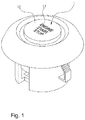
Korean Registered Patent Publication No. 10-1210906 FIGS. 1 and2 , alight emitting knob 1 includes a lightblocking metal plate 10 having a lightemitting display window 11 and aresin layer 20, made of a light-transmissive synthetic resin, coupled to the lower surface of the light blockingmetal plate 10. - The
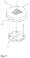
resin layer 20 is coupled to the lower part of the light blockingmetal plate 10 by bonding or by insert injection molding. In addition, referring toFIG. 2 , alight emitting device 30 is installed under theresin layer 20 to display a predetermined message, such as "ENGINE START STOP," outward through the lightemitting display window 11 of the light blockingmetal plate 10 in a light emitting fashion. - A method for manufacturing the conventional light emitting knob as described above will be described with reference to
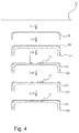
FIGS. 3 and4 . The method for manufacturing the conventional light emitting knob includes a metal plate processing step (S10) of processing a lightblocking metal plate 10 such that the upper part of the light blocking metal plate is closed and the lower part of the light blocking metal plate is open, a resin layer coupling step (S20) of coupling aresin layer 20, which is made of a light-transmissive synthetic resin, to the inner side of the lower part of the light blockingmetal plate 10, a display window forming step (S30) of forming a lightemitting display window 11 in the upper surface of the light blockingmetal plate 10 by carving, a surface treatment step (S40) of treating the upper surface of the light blockingmetal plate 10, in which the lightemitting display window 11 is formed, and a coating step (S50) of coating the treated upper surface of the light blockingmetal plate 10. - In the method for manufacturing the conventional light emitting knob, as shown in
FIG. 5 , letters, such as E, N, G, I, N, S, and T, the start and the end of a cutoff line of each of which are attached to the light blockingmetal plate 10, of "ENGINE START STOP," which is the message, displayed through the lightemitting display window 11, which is widely used, are not separated from theresin layer 20. However, the inner portions of letters, such as A, R, O, and P, which are separated from the light blockingmetal plate 10 with the result that only the bottom surfaces of the letters are attached to theresin layer 20, i.e. "Δ" of A, "D" of R and P, and "○" of O, are easily separated from theresin layer 20 when lightemitting display window 11 is formed by carving at the display window forming step (S30) and when the upper surface of the light blockingmetal plate 10 is treated at the surface treatment step (S40), whereby a defect rate is increased. - The present invention has been made to solve the above problems, and it is an object of the present invention to provide a method for manufacturing a light emitting knob based on a novel process that is capable of preventing a letter that is separated from a light blocking metal plate at a display window forming step and a surface treatment step from being separated from a resin layer irrespective of the shape or the type of the letter, which constitutes a light emitting display window, thereby considerably reducing a defect rate.
- Other objects, specific advantages, and novel features of the present invention will become apparent from the following description of embodiments given in conjunction with the accompanying drawing.
- In order to accomplish the above objects, a method for manufacturing a light emitting knob according to the present invention includes a metal plate processing step of processing a light blocking metal plate such that the upper part of the light blocking metal plate is closed and the lower part of the light blocking metal plate is open, a display groove forming step of forming a light emitting display groove in the inner surface of the upper side of the light blocking metal plate, a resin layer coupling step of forming a resin layer, which is made of a synthetic resin, by insert injection molding using the light blocking metal plate as an insert and coupling the light blocking metal plate to the resin layer such that the resin layer is coupled to the inner side of the lower part of the light blocking metal plate up to the light emitting display groove, and a display window forming step of evenly cutting the upper surface of the light blocking metal plate such that the resin layer coupled into the light emitting display groove is exposed from the upper surface of the light blocking metal plate to form a light emitting display window.
- In addition, the metal plate processing step may include processing a plate-shaped metal material by pressing to manufacture the light blocking metal plate.
- In addition, the method according to the present invention may further include a surface treatment step of treating the upper surface of the light blocking metal plate, in which the light emitting display window is formed.
- In addition, the surface treatment step may include forming hairlines on the upper surface of the light blocking metal plate or spinning the upper surface of the light blocking metal plate.
- In addition, the method according to the present invention may further include a coating step of coating the upper surface of the light blocking metal plate.
- In addition, the coating step may include coating the upper surface of the light blocking metal plate with hard urethane.
- The method for manufacturing the light emitting knob according to the present invention has the following effects. First, the light emitting display groove is formed in the lower surface of the light blocking metal plate at the display groove forming step, and then the resin layer coupling step is carried out such that the lower surface and the lateral surface of a letter, which will be separated from the light blocking metal plate, are securely coupled into the resin layer.
- Second, the upper surface of the light blocking metal plate is evenly cut at the display window forming step in order to form the light emitting display window. Consequently, it is possible to prevent the letter that is separated from the light blocking metal plate at the display window forming step and the surface treatment step from being separated from the resin layer irrespective of the shape or the type of the letter, thereby considerably reducing a defect rate.
-
-
FIG. 1 is a perspective view showing a general light emitting knob; -
FIG. 2 is an exploded perspective view of the light emitting knob in the embodiment shown inFIG. 1 ; -
FIG. 3 is a flowchart showing a method for manufacturing a conventional light emitting knob; -
FIG. 4 is a side sectional view showing, step by step, a process for manufacturing a light emitting knob in accordance with the flowchart of the embodiment shown inFIG. 3 ; -
FIG. 5 is a front view showing a light emitting knob that is manufactured in accordance with the embodiment shown inFIGS. 3 and4 ; -
FIG. 6 is a flowchart showing a first embodiment of a method for manufacturing a light emitting knob according to the present invention; -
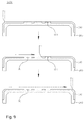
FIG. 7 is a side sectional view showing a process for manufacturing a light emitting knob per step in accordance with the flowchart of the embodiment shown inFIG. 6 ; -
FIG. 8 is a side sectional view of a principal part showing a process for manufacturing a light emitting knob at a display groove forming step in the embodiment shown inFIG. 7 ; -
FIG. 9 is a side sectional view of a principal part showing a process for manufacturing a light emitting knob at a display window forming step in the embodiment shown inFIG. 7 ; -
FIG. 10 is a flowchart showing a second embodiment of a method for manufacturing a light emitting knob according to the present invention; -
FIG. 11 is a side sectional view showing, step by step, a process for manufacturing a light emitting knob in accordance with the flowchart of the embodiment shown inFIG. 10 ; -
FIG. 12 is a front view showing a light emitting knob that is manufactured in accordance with the embodiment shown inFIGS. 10 and11 ; -
FIG. 13 is a flowchart showing a third embodiment of a method for manufacturing a light emitting knob according to the present invention; and -
FIG. 14 is a side sectional view showing, step by step, a process for manufacturing a light emitting knob in accordance with the flowchart of the embodiment shown inFIG. 13 . - Hereinafter, an exemplary embodiment of a method for manufacturing a light emitting knob according to the present invention will be described in detail with reference to the accompanying drawings.
- As shown in
FIGS. 6 to 9 , the method for manufacturing the light emitting knob according to the present invention may include a metal plate processing step (S100), a display groove forming step (S200), a resin layer coupling step (S300), and a display window forming step (S400). As shown inFIGS. 10 to 12 , the method for manufacturing the light emitting knob according to the present invention may further include a surface treatment step (S500). As shown inFIGS. 13 and14 , the method for manufacturing the light emitting knob according to the present invention may further include a coating step (S600). - At the metal plate processing step (S100), as shown in
FIGS. 6 and7 , a lightblocking metal plate 100 is processed such that the upper part of the lightblocking metal plate 100 is closed and the lower part of the lightblocking metal plate 100 is open. The light blockingmetal plate 100 is made of a plate-shaped metal material. As compared with a conventional synthetic resin, the light blockingmetal plate 100 has an aesthetically pleasing appearance due to the luxurious characteristics of metal. The light blockingmetal plate 100 has various shapes based on the function and type of the light emitting knob. As shown inFIG. 2 , the upper part of the lightblocking metal plate 100 is closed and the lower part of the lightblocking metal plate 100 is open such that the light blockingmetal plate 100 blocks light from thelight emitting device 30, which emits light under the light blockingmetal plate 100, and such that the lower part of the lightblocking metal plate 100 is coupled to thelight emitting device 30. The light blockingmetal plate 100 may be processed using various processing methods, such as cutting, casting, and injection molding, such that the upper part of the lightblocking metal plate 100 is closed and the lower part of the lightblocking metal plate 100 is open. As shown inFIG. 7 , however, a plate-shaped metal material may be processed by pressing to manufacture the light blockingmetal plate 100, which is most suitable for mass production, considering that the light blockingmetal plate 100 is made of a plate-shaped material. - At the display groove forming step (S200), as shown in
FIGS. 6 to 8 , a lightemitting display groove 110 is formed in the inner surface of the upper side of the light blockingmetal plate 100. In a case in which the lightblocking metal plate 100 is configured such that the upper part of the lightblocking metal plate 100 is closed and the lower part of the lightblocking metal plate 100 is open, as shown inFIGS. 6 to 8 , the lightblocking metal plate 100 has a '[' shape, in which the lower part of the lightblocking metal plate 100 is open when viewed in side section. The lightemitting display groove 110 is formed in the upper surface of the inner side of the light blockingmetal plate 100 or in the inner surface of the upper side of the light blockingmetal plate 100 such that the lightemitting display groove 110 has the same shape as a letter or a symbol of a lightemitting display window 120, which will be described hereinafter. As shown inFIGS. 7 and8 , carving may be used to form the lightemitting display groove 110 in the inner surface of the upper side of the lightblocking metal plate 100. Alternatively, various other processing methods, such as pressing, punching, and chemical hatching, may be used to form the lightemitting display groove 110 in the inner surface of the upper side of the light blockingmetal plate 100. Any processing methods may be used as long as, at the display groove forming step (S200), the lightemitting display groove 110 is formed in the inner surface of the upper side of the light blockingmetal plate 100 such that the lightemitting display groove 110 has the same shape as the lightemitting display window 120, which will be described hereinafter. - Meanwhile, it may seem that the display groove forming step (S200) is carried out after the metal plate processing step (S100) considering the order of the reference symbols or the sequence of the flowchart shown in the drawings. However, the sequence in which the metal plate processing step (S100) and the display groove forming step (S200) are carried out is not particularly restricted. That is, at the display groove forming step (S200), the light emitting
display groove 110 may be formed in advance in a portion of the plate-shaped metal material which will become the inner surface of the upper side of the light blockingmetal plate 100 at the metal plate processing step (S100), and then the metal plate processing step (S100) may be carried out. Alternatively, the metal plate processing step (S100) and the display groove forming step (S200) may be simultaneously carried out such that the light blockingmetal plate 100 is processed by pressing simultaneously when the light emittingdisplay groove 110 is formed. - At the resin layer coupling step (S300), a
resin layer 200, which is made of a synthetic resin, is coupled to the inner side of the lower part of the light blockingmetal plate 100. Since theresin layer 200 is made of a light transmissive synthetic resin, light emitted from thelight emitting device 30 may be transmitted through theresin layer 200 such that the light reaches the light blockingmetal plate 100. Although not shown in the drawings, theresin layer 200 may be provided at the lower part thereof with a bracket, a protrusion, or a protruding recess such that theresin layer 200 can be coupled with another member. In a case in which theresin layer 200 is coupled to the inner side of the lower part of the light blockingmetal plate 100, theresin layer 200 may be manufactured in advance so as to have a shape in which theresin layer 200 can be inserted into and fitted in the light blockingmetal plate 100, and may then be coupled to the light blockingmetal plate 100 by bonding. Alternatively, theresin layer 200 may be formed by insert injection molding using the light blockingmetal plate 100 as an insert such that the light blockingmetal plate 100 is coupled to theresin layer 200. - At the display window forming step (S400), as shown in
FIGS. 6 ,7 , and9 , the upper surface of the light blockingmetal plate 100 is evenly cut such that the light emittingdisplay groove 110 is exposed from the upper surface of the light blockingmetal plate 100 to form a light emittingdisplay window 120. That is, after the light emittingdisplay groove 110 is formed at the display groove forming step (S200) and theresin layer 200 is coupled to the light blockingmetal plate 100, light that is emitted from thelight emitting device 30 and reaches the light blockingmetal plate 100 cannot be emitted upward since the upper surface of the light emittingdisplay groove 110 is closed. - In a case in which the upper surface of the light blocking
metal plate 100 is evenly cut up to the upper end of the light emittingdisplay groove 110, the light emittingdisplay groove 110 is exposed upward with the result that the groove is becomes a hole or an open window, which constitutes the light emittingdisplay window 120. - In the method for manufacturing the light emitting knob according to the present invention, as described above, the light emitting
display groove 110 is formed in the lower surface of the light blockingmetal plate 100 at the display groove forming step (S200), and then the resin layer coupling step (S300) is carried out such that the lower surface and the lateral surface of a letter, which will be separated from the light blockingmetal plate 100, are securely coupled into theresin layer 200. Subsequently, at the display window forming step (S400), the upper surface of the light blockingmetal plate 100 is evenly cut in order to form the light emittingdisplay window 120. Consequently, it is possible to prevent the letter that is separated from the light blockingmetal plate 100 at the display window forming step (S400) and a surface treatment step (S500), which will be described hereinafter, from being separated from theresin layer 200 irrespective of the shape or the type of the letter, thereby considerably reducing a defect rate. - At the surface treatment step (S500), as shown in
FIGS. 10 and11 , the upper surface of the light blockingmetal plate 100, in which the light emittingdisplay window 120 is formed, is treated. Surface treatment includes plating or painting performed on the surface of a material such that the material exhibits high corrosion resistance, smoothness, and hardness. As shown inFIG. 12 , surface treatment further includes forminghairlines 300 on the upper surface of the light blockingmetal plate 100 or spinning the upper surface of the light blockingmetal plate 100. The letter that is separated from the light blockingmetal plate 100 at the surface treatment step (S500) may be easily separated from theresin layer 200. In the method for manufacturing the light emitting knob according to the present invention, as described above, the lower surface and the lateral surface of the letter that is separated from the light blockingmetal plate 100 is securely coupled into theresin layer 200 in a buried state, whereby it is possible to prevent the letter from being separated from theresin layer 200. - At the coating step (S600), as shown in
FIGS. 13 and14 , the upper surface of the light blockingmetal plate 100 is coated. Coating includes putting a thin film of paraffin, rubber resin, or a chemical material on the surface of a material. In the present invention, the surface of the light blockingmetal plate 100 is coated withhard urethane 400. In a case in which liquid urethane is mixed with a pigment having various colors, thehard urethane 400 is formed in a semi-transparent state. The upper surface of the light blockingmetal plate 100 is coated with thehard urethane 400, and is then dried. As a result, it is possible to improve the visibility of light emitted through the light emittingdisplay window 120. In addition, in a case in which the light blockingmetal plate 100 is coated with thehard urethane 400, it is possible to avoid leaving fingerprints on the upper surface of the light blockingmetal plate 100 and to provide the light blockingmetal plate 100 with an aesthetically pleasing appearance. - It must not be interpreted that the preferred embodiments of the present invention, which have been described above and shown in the drawings, define the technical idea of the present invention. The scope of protection of the present invention is limited by what is claimed in the claims, and various modifications and variations of the technical idea of the present invention can be made by those skilled in the art to which the present invention pertains. Therefore, such modifications and variations will fall into the scope of protection of the present invention as far as they are obvious to those skilled in the art.
-
- 1:
- Light emitting knob
- 100:
- Light blocking metal plate
- 110:
- Light emitting display groove
- 120:
- Light emitting display window
- 200:
- Resin layer
- 300:
- Hairlines
- 400:
- Coating layer
- S100:
- Metal plate processing step
- S200:
- Display groove forming step
- S300:
- Resin layer coupling step
- S400:
- Display window forming step
- S500:
- Surface treatment step
- S600:
- Coating step
Claims (6)
- A method for manufacturing a light emitting knob comprising:a metal plate processing step of processing a light blocking metal plate such that an upper part of the light blocking metal plate is closed and a lower part of the light blocking metal plate is open;a display groove forming step of forming a light emitting display groove in an inner surface of an upper side of the light blocking metal plate;a resin layer coupling step of forming a resin layer, which is made of a synthetic resin, by insert injection molding using the light blocking metal plate as an insert and coupling the light blocking metal plate to the resin layer such that the resin layer is coupled to an inner side of a lower part of the light blocking metal plate up to the light emitting display groove; anda display window forming step of evenly cutting an upper surface of the light blocking metal plate such that the resin layer coupled into the light emitting display groove is exposed from the upper surface of the light blocking metal plate to form a light emitting display window.
- The method according to claim 1, wherein the metal plate processing step comprises processing a plate-shaped metal material by pressing to manufacture the light blocking metal plate.
- The method according to claim 1, further comprising a surface treatment step of treating the upper surface of the light blocking metal plate, in which the light emitting display window is formed.
- The method according to claim 3, wherein the surface treatment step comprises forming hairlines on the upper surface of the light blocking metal plate or spinning the upper surface of the light blocking metal plate.
- The method according to claim 3, further comprising a coating step of coating the upper surface of the light blocking metal plate.
- The method according to claim 5, wherein the coating step comprises coating the upper surface of the light blocking metal plate with hard urethane.
Applications Claiming Priority (1)
| Application Number | Priority Date | Filing Date | Title |
|---|---|---|---|
| KR1020150006927A KR101560998B1 (en) | 2015-01-14 | 2015-01-14 | Apparatus for manufacturing light emitting knob |
Publications (1)
| Publication Number | Publication Date |
|---|---|
| EP3046125A1 true EP3046125A1 (en) | 2016-07-20 |
Family
ID=54357139
Family Applications (1)
| Application Number | Title | Priority Date | Filing Date |
|---|---|---|---|
| EP15201610.1A Withdrawn EP3046125A1 (en) | 2015-01-14 | 2015-12-21 | Method for manufacturing light emitting knob |
Country Status (5)
| Country | Link |
|---|---|
| US (1) | US9416942B2 (en) |
| EP (1) | EP3046125A1 (en) |
| JP (1) | JP5970599B2 (en) |
| KR (1) | KR101560998B1 (en) |
| WO (1) | WO2016114499A1 (en) |
Cited By (2)
| Publication number | Priority date | Publication date | Assignee | Title |
|---|---|---|---|---|
| EP3376517A4 (en) * | 2017-01-20 | 2019-07-24 | Jae Ho Choi | Light emitting metal knob manufacturing method |
| EP3594775A1 (en) * | 2018-07-09 | 2020-01-15 | Marquardt GmbH | Component with an image element and manufacturing process of the component |
Families Citing this family (4)
| Publication number | Priority date | Publication date | Assignee | Title |
|---|---|---|---|---|
| KR20170136909A (en) * | 2016-06-02 | 2017-12-12 | 유아이엘 주식회사 | Method for manufacturing metal logo |
| KR101912763B1 (en) * | 2016-06-16 | 2018-10-29 | 주식회사 한라캐스트 | Imprinting method of product and product using the same |
| KR101912762B1 (en) * | 2016-06-16 | 2018-10-29 | 주식회사 한라캐스트 | Imprinting method of product and product using the same |
| USD1090567S1 (en) * | 2022-03-21 | 2025-08-26 | Alfred Kaercher Se & Co. Kg | Circular controls surrounding a display screen |
Citations (6)
| Publication number | Priority date | Publication date | Assignee | Title |
|---|---|---|---|---|
| DE10018933C1 (en) * | 2000-04-17 | 2001-11-15 | Harman Becker Automotive Sys | Push-button element for electrical video or audio device e.g. car radio, has base body provided with symbol island surrounded by gap filled with transparent plastics filling material block |
| KR101210906B1 (en) | 2012-06-27 | 2012-12-11 | 나순희 | Light emitting control knob |
| EP2589480A1 (en) * | 2011-11-02 | 2013-05-08 | Research In Motion Limited | Keyboards and method of manufacturing same |
| KR101370256B1 (en) * | 2013-10-28 | 2014-03-25 | 유재진 | Light emitting control knob and its manufacturing method |
| EP2727692A2 (en) * | 2012-11-06 | 2014-05-07 | Sembach GmbH & Co. KG | Method for producing a sinter composite component and sinter composite component |
| KR101412781B1 (en) * | 2013-12-06 | 2014-07-09 | 주식회사 엠엘케이 | Method of manufacturing knob with function of light emission |
Family Cites Families (5)
| Publication number | Priority date | Publication date | Assignee | Title |
|---|---|---|---|---|
| US5036440A (en) * | 1989-05-23 | 1991-07-30 | Alps Electric Co., Ltd. | Illumination type keytop |
| JPH09320381A (en) * | 1996-05-29 | 1997-12-12 | Niles Parts Co Ltd | Switch knob lighting system |
| JP2010125773A (en) * | 2008-11-28 | 2010-06-10 | Sakaiya:Kk | Method for manufacturing synthetic resin molded article |
| JP2015001132A (en) | 2013-06-18 | 2015-01-05 | 群馬合金株式会社 | Door knob with led lighting |
| KR101370186B1 (en) | 2013-09-27 | 2014-03-05 | 김권일 | Knob structure and manufacturing method thereof |
-
2015
- 2015-01-14 KR KR1020150006927A patent/KR101560998B1/en not_active Expired - Fee Related
- 2015-12-03 US US14/958,091 patent/US9416942B2/en not_active Expired - Fee Related
- 2015-12-08 WO PCT/KR2015/013398 patent/WO2016114499A1/en not_active Ceased
- 2015-12-21 EP EP15201610.1A patent/EP3046125A1/en not_active Withdrawn
- 2015-12-29 JP JP2015257612A patent/JP5970599B2/en not_active Expired - Fee Related
Patent Citations (6)
| Publication number | Priority date | Publication date | Assignee | Title |
|---|---|---|---|---|
| DE10018933C1 (en) * | 2000-04-17 | 2001-11-15 | Harman Becker Automotive Sys | Push-button element for electrical video or audio device e.g. car radio, has base body provided with symbol island surrounded by gap filled with transparent plastics filling material block |
| EP2589480A1 (en) * | 2011-11-02 | 2013-05-08 | Research In Motion Limited | Keyboards and method of manufacturing same |
| KR101210906B1 (en) | 2012-06-27 | 2012-12-11 | 나순희 | Light emitting control knob |
| EP2727692A2 (en) * | 2012-11-06 | 2014-05-07 | Sembach GmbH & Co. KG | Method for producing a sinter composite component and sinter composite component |
| KR101370256B1 (en) * | 2013-10-28 | 2014-03-25 | 유재진 | Light emitting control knob and its manufacturing method |
| KR101412781B1 (en) * | 2013-12-06 | 2014-07-09 | 주식회사 엠엘케이 | Method of manufacturing knob with function of light emission |
Cited By (2)
| Publication number | Priority date | Publication date | Assignee | Title |
|---|---|---|---|---|
| EP3376517A4 (en) * | 2017-01-20 | 2019-07-24 | Jae Ho Choi | Light emitting metal knob manufacturing method |
| EP3594775A1 (en) * | 2018-07-09 | 2020-01-15 | Marquardt GmbH | Component with an image element and manufacturing process of the component |
Also Published As
| Publication number | Publication date |
|---|---|
| US9416942B2 (en) | 2016-08-16 |
| WO2016114499A1 (en) | 2016-07-21 |
| JP5970599B2 (en) | 2016-08-17 |
| US20160201878A1 (en) | 2016-07-14 |
| KR101560998B1 (en) | 2015-10-15 |
| JP2016131145A (en) | 2016-07-21 |
Similar Documents
| Publication | Publication Date | Title |
|---|---|---|
| US9416942B2 (en) | Method for manufacturing light emitting knob | |
| US9443676B2 (en) | Light emitting control knob | |
| EP3376517B1 (en) | Light emitting metal knob manufacturing method | |
| EP3515678B1 (en) | Selectively chrome plated vehicle radome and methods of manufacturing | |
| US20170324157A1 (en) | Three piece vehicle radome | |
| US6591457B1 (en) | Multi-component button and a method of manufacturing it | |
| CN102483607B (en) | Method of manufacturing a part decorated with embossments | |
| US20140106109A1 (en) | Metal ornament and method for manufacturing metal ornament | |
| KR20180129039A (en) | Glass decoration film and the manufacturing method thereof | |
| US10648098B2 (en) | Plastic part with selective metallization and corresponding manufacturing process | |
| KR20170127124A (en) | Lighting button key making method | |
| CN104715949B (en) | The method that manufacture was used to open/closed the turntable knob of ventilation hole | |
| KR101560999B1 (en) | Apparatus for manufacturing light emitting knob | |
| CN110177713B (en) | Display element, method for producing a display element, use of a display element and vehicle having a display element | |
| KR101561000B1 (en) | Apparatus for manufacturing light emitting knob | |
| DE102007034110A1 (en) | Operating knob for motor vehicle, has opaque material covering translucent material, where translucent material touches upto outside surface of knob and knob is integrally formed within display area | |
| US20130059108A1 (en) | Decorative element, dashboard, and method for manufacturing a decorative element | |
| EP3210743A1 (en) | Injection molded part with insert film | |
| JP5188877B2 (en) | Decorative parts manufacturing method | |
| KR101795456B1 (en) | Manufacturing method for a button having an isolated shape of characters | |
| CN208210040U (en) | A kind of cover board with blind hole and pattern structure | |
| US10525621B2 (en) | Synthetic resin molded-article and method for molding same | |
| US20150273288A1 (en) | Iron golf club head and iron golf club | |
| JP2008100415A (en) | Method for producing decorative resin molding | |
| FR2861885A1 (en) | METHOD FOR MANUFACTURING A DISPLAY AREA HAVING AT LEAST ONE SYMBOL THAT CAN BE BACKLIGHT |
Legal Events
| Date | Code | Title | Description |
|---|---|---|---|
| PUAI | Public reference made under article 153(3) epc to a published international application that has entered the european phase |
Free format text: ORIGINAL CODE: 0009012 |
|
| AK | Designated contracting states |
Kind code of ref document: A1 Designated state(s): AL AT BE BG CH CY CZ DE DK EE ES FI FR GB GR HR HU IE IS IT LI LT LU LV MC MK MT NL NO PL PT RO RS SE SI SK SM TR |
|
| AX | Request for extension of the european patent |
Extension state: BA ME |
|
| STAA | Information on the status of an ep patent application or granted ep patent |
Free format text: STATUS: THE APPLICATION IS DEEMED TO BE WITHDRAWN |
|
| 18D | Application deemed to be withdrawn |
Effective date: 20170121 |