EP3046087A1 - Remote controller - Google Patents
Remote controller Download PDFInfo
- Publication number
- EP3046087A1 EP3046087A1 EP14844720.4A EP14844720A EP3046087A1 EP 3046087 A1 EP3046087 A1 EP 3046087A1 EP 14844720 A EP14844720 A EP 14844720A EP 3046087 A1 EP3046087 A1 EP 3046087A1
- Authority
- EP
- European Patent Office
- Prior art keywords
- panel
- arc
- rotating shaft
- shaped sliding
- remote controller
- Prior art date
- Legal status (The legal status is an assumption and is not a legal conclusion. Google has not performed a legal analysis and makes no representation as to the accuracy of the status listed.)
- Granted
Links
Images



Classifications
-
- G—PHYSICS
- G08—SIGNALLING
- G08C—TRANSMISSION SYSTEMS FOR MEASURED VALUES, CONTROL OR SIMILAR SIGNALS
- G08C17/00—Arrangements for transmitting signals characterised by the use of a wireless electrical link
- G08C17/02—Arrangements for transmitting signals characterised by the use of a wireless electrical link using a radio link
-
- H—ELECTRICITY
- H05—ELECTRIC TECHNIQUES NOT OTHERWISE PROVIDED FOR
- H05K—PRINTED CIRCUITS; CASINGS OR CONSTRUCTIONAL DETAILS OF ELECTRIC APPARATUS; MANUFACTURE OF ASSEMBLAGES OF ELECTRICAL COMPONENTS
- H05K5/00—Casings, cabinets or drawers for electric apparatus
- H05K5/0026—Casings, cabinets or drawers for electric apparatus provided with connectors and printed circuit boards [PCB], e.g. automotive electronic control units
-
- H—ELECTRICITY
- H05—ELECTRIC TECHNIQUES NOT OTHERWISE PROVIDED FOR
- H05K—PRINTED CIRCUITS; CASINGS OR CONSTRUCTIONAL DETAILS OF ELECTRIC APPARATUS; MANUFACTURE OF ASSEMBLAGES OF ELECTRICAL COMPONENTS
- H05K5/00—Casings, cabinets or drawers for electric apparatus
- H05K5/02—Details
- H05K5/03—Covers
-
- H—ELECTRICITY
- H05—ELECTRIC TECHNIQUES NOT OTHERWISE PROVIDED FOR
- H05K—PRINTED CIRCUITS; CASINGS OR CONSTRUCTIONAL DETAILS OF ELECTRIC APPARATUS; MANUFACTURE OF ASSEMBLAGES OF ELECTRICAL COMPONENTS
- H05K5/00—Casings, cabinets or drawers for electric apparatus
- H05K5/10—Casings, cabinets or drawers for electric apparatus comprising several parts forming a closed casing
Definitions
- the present invention relates to the field of remote control technologies, and in particular, to a rotatable remote controller.
- a main objective of the present invention is to provide a remote controller, to decrease outline size of the remote controller on the basis of ensuring that function buttons have enough accommodation space, thereby facilitating users to operate the remote controller.
- the present invention provides a remote controller, including a first panel and a second panel that are provided with multiple function buttons, where the first panel is rotationally connected to the second panel by using a rotating connecting mechanism;
- the rotating connecting mechanism includes a fixation base fixed to the first panel, a rotating shaft fixed to the second panel, and a sliding component;
- the sliding component includes an arc-shaped sliding rail disposed in the circumference direction of an outer sidewall of the rotating shaft, elastic pieces disposed on the fixation base in the axial direction of the rotating shaft and provided with circular holes, and rolling balls disposed between the arc-shaped sliding rail and the circular holes in an abutted mode;
- the arc-shaped sliding rail is fitted to the rolling balls in a sliding mode; and two ends of the arc-shaped sliding rail are higher than the middle of the arc-shaped sliding rail in the axial direction of the rotating shaft.
- the radius of the circular holes is less than that of the rolling balls.
- the two ends of the arc-shaped sliding rail are identical in height in the axial direction of the rotating shaft; when the ends of the arc-shaped sliding rail slide to the rolling balls, a distance between the first panel and the second panel is minimum in the axial direction of the rotating shaft.
- a central position of the arc-shaped sliding rail is the lowest point in height in the axial direction of the rotating shaft; when the central position of the arc-shaped sliding rail slides to a corresponding rolling ball, the distance between the first panel and the second panel is maximum in the axial direction of the rotating shaft.
- At least two groups of sliding components are disposed, and arc-shaped sliding rails corresponding to the at least two groups of sliding components are evenly distributed in the circumference direction of the outer sidewall of the rotating shaft; circular holes corresponding to the at least two groups of sliding components are evenly distributed on a circumference where the circular holes are located.
- the rotating connecting mechanism further includes a cover plate fixed to the fixation base, the cover plate being provided with an annular through hole that accommodates the rotating shaft; positions, which correspond to the elastic pieces, on a sidewall of the annular through hole are provided with openings; the width of the openings is greater than or equal to the diameter of the rolling balls and less than the width of the elastic pieces, so that the corresponding rolling balls are disposed between the circular holes of the elastic pieces and the corresponding arc-shaped sliding rails.
- two sides of the elastic pieces are provided with bumps that are in contact with the elastic pieces in an abutted mode.
- the two ends of the arc-shaped sliding rails are separately set to be in a shape of an arc-shaped groove.
- a radical included angle between the two ends of the arc-shaped sliding rails is 90 degrees.
- the fixation base is fixed to a central position of the first panel
- the rotating shaft is fixed to a central position of the second panel, so that the central position of the first panel is rotationally connected to the central position of the second panel
- a channel that accommodates an FPC is disposed inside the rotating shaft, and the FPC enables the first panel to be electrically connected to the second panel.
- the present invention provides a remote controller.
- the remote controller includes a first panel and a second panel that are provided with multiple function buttons, and the first panel is rotationally connected to the second panel by using a rotating connecting mechanism; therefore, on the basis that the function buttons have enough accommodation space, outline size of the remote controller is reduced, thereby facilitating users to operate the remote controller.
- an arc-shaped sliding rail is disposed in the circumference direction of an outer sidewall of a rotating shaft of the rotating connecting mechanism, elastic pieces are disposed on a fixation base in the axial direction of the rotating shaft and provided with circular holes, rolling balls are disposed between the arc-shaped sliding rail and the circular holes in an abutted mode, and in the axial direction of the rotating shaft, the height of one end of the arc-shaped sliding rail to the other end gradually decreases and then gradually increases; therefore, in a process that a user rotates the second panel to turn off or turn on the remote controller, a gap will be generated between the first panel and the second panel, which can effectively prevent the function buttons of the first panel from rubbing against the bottom of the second panel, thereby ensuring that the function buttons of the first panel are prevented from being abraded and damaged in the process of turning off or turning on the remote controller, improving the quality of the remote controller, and prolonging the service life of the remote controller.
- the remote controller 100 includes a first panel 110 and a second panel 120 that are provided with multiple function buttons.
- the first panel 110 is rotationally connected to the second panel 120 by using a rotating connecting mechanism 130.
- the rotating connecting mechanism 130 includes a fixation base 140 fixed to the first panel 110, a rotating shaft 150 fixed to the second panel 120, and a sliding component.
- the sliding component includes an arc-shaped sliding rail 151 disposed in the circumference direction of an outer sidewall of the rotating shaft 150, elastic pieces 141 disposed on the fixation base 140 in the axial direction of the rotating shaft 150 and provided with circular holes 142, and rolling balls 160 disposed between the arc-shaped sliding rail 151 and the circular holes 142 in an abutted mode.
- the arc-shaped sliding rail 151 is fitted to the rolling balls 160 in a sliding mode. Two ends of the arc-shaped sliding rail 151 are higher than the middle of the arc-shaped sliding rail 151 in the axial direction of the rotating shaft 150. That is, when the rolling ball 160 is in a position of one end of the arc-shaped sliding rail 151, the first panel 110 and the second panel 120 are in an overlapped or fully-opened state.
- the two ends of the arc-shaped sliding rail 151 are identical in height in the axial direction of the rotating shaft 150, and a central position of the arc-shaped sliding rail 151 is the lowest point in height in the axial direction of the rotating shaft 150.
- the two ends of the arc-shaped sliding rail 151 are separately set to be in a shape of an arc-shaped groove.
- one end of the arc-shaped sliding rail 151 is marked as 1511, and the other end is marked as 1512. It may be set that when the rolling ball 160 abuts between the end 1511 and a corresponding circular hole 142, the first panel 110 and the second panel 120 are in an overlapped state, as shown in FIG. 1 ; and when the rolling ball 160 abuts between the end 1512 and the corresponding circular hole 142, the first panel 110 and the second panel 120 are in a fully-opened state, as shown in FIG. 2 and FIG. 3 .
- the height of one end of the arc-shaped sliding rail 151 to the other end gradually decreases and then gradually increases, while the circular hole 142 and the rolling ball 160 remain unchanged in height in the axial direction of the rotating shaft 150, so, when a user needs to change the first panel 110 and the second panel 120 from the overlapped state into a fully-opened state (before opening, the end 1511 of the arc-shaped sliding rail 151 is disposed at a corresponding rolling ball), the user should rotate the second panel 120 anticlockwise, and in a process of rotating the second panel 120 anticlockwise, the arc-shaped sliding rail 151 slides along the corresponding rolling ball 160.
- the second panel 120 While making anticlockwise rotation, the second panel 120 moves to a direction away from the first panel 110 in the axial direction of the rotating shaft 150.
- the distance between the first panel 110 and the second panel 120 is maximum in the axial direction of the rotating shaft 150 (spacing between the first panel 110 and the second panel 120 is maximum).
- the second panel 120 if the second panel 120 is rotated anticlockwise continuously, while making anticlockwise rotation, the second panel 120 moves to a direction close to the first panel 110 in the axial direction of the rotating shaft 150 until the end 1512 of the arc-shaped sliding rail 151 slides to the rolling ball 160.
- the first panel 110 and the second panel 120 are in a fully-opened state and the distance between the first panel 110 and the second panel 120 in the axial direction of the rotating shaft 150 is restored (spacing between the first panel 110 and the second panel 120 is minimum).
- the user When the user needs to change the first panel 110 and the second panel 120 from the opened state into the overlapped state (in a fully-opened state, the end 1512 of the arc-shaped sliding rail 151 is disposed in a corresponding rolling ball 160), the user should rotate the second panel 120 clockwise, and in a process of rotating the second panel 120 clockwise, the arc-shaped sliding rail 151 slides along the corresponding rolling ball 160. While making clockwise rotation, the second panel 120 moves to a direction away from the first panel 110 in the axial direction of the rotating shaft 150.
- the distance between the first panel 110 and the second panel 120 is maximum in the axial direction of the rotating shaft 150 (spacing between the first panel 110 and the second panel 120 is maximum).
- the second panel 120 is rotated clockwise continuously, while making clockwise rotation, the second panel 120 moves to a direction close to the first panel 110 in the axial direction of the rotating shaft 150 until the end 1511 of the arc-shaped sliding rail 151 slides to the rolling ball 160.
- the first panel 110 and the second panel 120 are in an overlapped state and the distance between the first panel 110 and the second panel 120 in the axial direction of the rotating shaft 150 is restored (spacing between the first panel 110 and the second panel 120 is minimum).
- the remote controller 100 in this embodiment may also be set as follows: when the rolling ball 160 abuts between the end 1511 and a corresponding circular hole 142, the first panel 110 and the second panel 120 are in a fully-opened state; and when the rolling ball 160 abuts between the end 1512 and the corresponding circular hole 142, the first panel 110 and the second panel 120 are in an overlapped state.
- the second panel 120 should be rotated clockwise.
- the second panel 120 should be rotated anticlockwise.
- the remote controller 100 in a process of turning off or turning on the remote controller 100, a gap will be generated between the first panel 110 and the second panel 120, so that a phenomenon that function buttons 101 on the first panel 110 rub against the bottom of the second panel 120 can be effectively prevented, thereby ensuring that the function buttons 101 of the first panel 110 are prevented from being abraded and damaged in the process of turning off or turning on the remote controller 100, improving the quality of the remote controller 100, and prolonging the service life of the remote controller 100.
- the radius of the circular hole 142 is less than that of the rolling ball 160, to ensure that the rolling ball 160 will not slide out of the circular hole 142.
- the rolling ball 160 is made from a rigid material, for example, a steel material.
- At least two groups of sliding components are disposed, and at least two arc-shaped sliding rails 151 corresponding to the at least two groups of sliding components are evenly distributed in the circumference direction of the outer sidewall of the rotating shaft 150; and at least two circular holes 142 corresponding to the at least two groups of sliding components are evenly distributed on a circumference where the circular holes 142 are located.
- at least two arc-shaped sliding rails 151 corresponding to the at least two groups of sliding components are evenly distributed in the circumference direction of the outer sidewall of the rotating shaft 150; and at least two circular holes 142 corresponding to the at least two groups of sliding components are evenly distributed on a circumference where the circular holes 142 are located.
- three groups of sliding components are disposed; and three arc-shaped sliding rails 151 corresponding to the three groups of sliding components are evenly distributed in the circumference direction of the outer sidewall of the rotating shaft 150; and three circular holes 142 corresponding thereto are evenly distributed on a circumference where the circular holes 142 are located.
- a radical included angle between the two ends of the arc-shaped sliding rail 151 is 90 degrees.
- the first panel 110 and the second panel 120 when the first panel 110 and the second panel 120 are in an overlapped state, it is only necessary to rotate the second panel 120 90 degrees relative to the first panel 110. In this way, the first panel 110 and the second panel 120 may be fully opened.
- the first panel 110 and the second panel 120 when the first panel 110 and the second panel 120 are in a fully-opened state, it is only necessary to rotate the second panel 120 90 degrees relative to the first panel 110. In this way, the first panel 110 and the second panel 120 may be closed, so that the first panel 110 and the second panel 120 are in an overlapped state.
- degrees of a maximum included angle at which the first panel 110 and the second panel 120 can be opened may be adjusted.
- the fixation base 140 may be fixed to a central position of the first panel 110, and the rotating shaft 150 is fixed to a central position of the second panel 120, so that the central position of the first panel 110 is rotationally connected to the central position of the second panel 120.
- FIG. 3 when the first panel 110 and the second panel 120 are in a fully-opened state, an included angle between a length direction of the first panel 110 and a length direction of the second panel 120 is 90 degrees, that is, the two length directions are perpendicular to each other and cross-shaped.
- a channel 102 that accommodates an FPC is disposed inside the rotating shaft 150, and the FPC enables the first panel 110 to be electrically connected to the second panel 120.
- the rotating connecting mechanism 130 further includes a cover plate 170 fixed to the fixation base 140, the cover plate 170 being provided with an annular through hole 171 that accommodates the rotating shaft 150; positions, which correspond to the elastic pieces 141, on a sidewall of the annular through hole 171 are provided with openings 172, so that the rolling balls 160 are disposed between the circular holes 142 of the elastic pieces 141 and the corresponding arc-shaped sliding rails 151.
- the width of the openings 172 is greater than or equal to the diameter of the rolling balls 160 and less than the width of the elastic pieces 141, to prevent the rolling balls 160 from sliding out of the arc-shaped sliding rails 151.
- the cover plate 170 is connected to the fixation base 140
- two sides of the elastic pieces 141 are provided with bumps 173 that are in contact with the elastic pieces 141 in an abutted mode.
- setting of the openings 172 enables the rolling balls 160 to be located precisely, which can prevent the rolling ball 160 from sliding out of the arc-shaped sliding rails 151 effectively.
- setting of the bumps 173 may protect the elastic pieces 141 from being deformed.
Landscapes
- Engineering & Computer Science (AREA)
- Microelectronics & Electronic Packaging (AREA)
- Computer Networks & Wireless Communication (AREA)
- Physics & Mathematics (AREA)
- General Physics & Mathematics (AREA)
- Selective Calling Equipment (AREA)
- Casings For Electric Apparatus (AREA)
Abstract
Description
- The present invention relates to the field of remote control technologies, and in particular, to a rotatable remote controller.
- With multifunctionalization of a TV, function buttons on a remote controller of the TV also gradually increase correspondingly. However, all traditional remote controllers are bar-shaped. With increase of the function buttons, such bar-shaped remote controllers can meet a requirement for space that accommodates the function buttons only be lengthening operation panels, so that outline size of the remote controllers increases and it is difficult to operate the remote controllers.
- A main objective of the present invention is to provide a remote controller, to decrease outline size of the remote controller on the basis of ensuring that function buttons have enough accommodation space, thereby facilitating users to operate the remote controller.
- The present invention provides a remote controller, including a first panel and a second panel that are provided with multiple function buttons, where the first panel is rotationally connected to the second panel by using a rotating connecting mechanism; the rotating connecting mechanism includes a fixation base fixed to the first panel, a rotating shaft fixed to the second panel, and a sliding component; the sliding component includes an arc-shaped sliding rail disposed in the circumference direction of an outer sidewall of the rotating shaft, elastic pieces disposed on the fixation base in the axial direction of the rotating shaft and provided with circular holes, and rolling balls disposed between the arc-shaped sliding rail and the circular holes in an abutted mode; the arc-shaped sliding rail is fitted to the rolling balls in a sliding mode; and two ends of the arc-shaped sliding rail are higher than the middle of the arc-shaped sliding rail in the axial direction of the rotating shaft.
- Preferably, the radius of the circular holes is less than that of the rolling balls.
- Preferably, the two ends of the arc-shaped sliding rail are identical in height in the axial direction of the rotating shaft; when the ends of the arc-shaped sliding rail slide to the rolling balls, a distance between the first panel and the second panel is minimum in the axial direction of the rotating shaft.
- Preferably, a central position of the arc-shaped sliding rail is the lowest point in height in the axial direction of the rotating shaft; when the central position of the arc-shaped sliding rail slides to a corresponding rolling ball, the distance between the first panel and the second panel is maximum in the axial direction of the rotating shaft.
- Preferably, at least two groups of sliding components are disposed, and arc-shaped sliding rails corresponding to the at least two groups of sliding components are evenly distributed in the circumference direction of the outer sidewall of the rotating shaft; circular holes corresponding to the at least two groups of sliding components are evenly distributed on a circumference where the circular holes are located.
- Preferably, the rotating connecting mechanism further includes a cover plate fixed to the fixation base, the cover plate being provided with an annular through hole that accommodates the rotating shaft; positions, which correspond to the elastic pieces, on a sidewall of the annular through hole are provided with openings; the width of the openings is greater than or equal to the diameter of the rolling balls and less than the width of the elastic pieces, so that the corresponding rolling balls are disposed between the circular holes of the elastic pieces and the corresponding arc-shaped sliding rails.
- Preferably, on one end where the cover plate is connected to the fixation base, two sides of the elastic pieces are provided with bumps that are in contact with the elastic pieces in an abutted mode.
- Preferably, the two ends of the arc-shaped sliding rails are separately set to be in a shape of an arc-shaped groove.
- Preferably, a radical included angle between the two ends of the arc-shaped sliding rails is 90 degrees.
- Preferably, the fixation base is fixed to a central position of the first panel, and the rotating shaft is fixed to a central position of the second panel, so that the central position of the first panel is rotationally connected to the central position of the second panel; a channel that accommodates an FPC is disposed inside the rotating shaft, and the FPC enables the first panel to be electrically connected to the second panel.
- The present invention provides a remote controller. The remote controller includes a first panel and a second panel that are provided with multiple function buttons, and the first panel is rotationally connected to the second panel by using a rotating connecting mechanism; therefore, on the basis that the function buttons have enough accommodation space, outline size of the remote controller is reduced, thereby facilitating users to operate the remote controller. Moreover, an arc-shaped sliding rail is disposed in the circumference direction of an outer sidewall of a rotating shaft of the rotating connecting mechanism, elastic pieces are disposed on a fixation base in the axial direction of the rotating shaft and provided with circular holes, rolling balls are disposed between the arc-shaped sliding rail and the circular holes in an abutted mode, and in the axial direction of the rotating shaft, the height of one end of the arc-shaped sliding rail to the other end gradually decreases and then gradually increases; therefore, in a process that a user rotates the second panel to turn off or turn on the remote controller, a gap will be generated between the first panel and the second panel, which can effectively prevent the function buttons of the first panel from rubbing against the bottom of the second panel, thereby ensuring that the function buttons of the first panel are prevented from being abraded and damaged in the process of turning off or turning on the remote controller, improving the quality of the remote controller, and prolonging the service life of the remote controller.
-
-
FIG. 1 is a schematic structural diagram of a remote controller in an off state according to the present invention; -
FIG. 2 is a schematic structural diagram of a remote controller in a fully-opened state according to the present invention; -
FIG. 3 is a top view ofFIG. 2 ; -
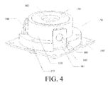
FIG. 4 is an assembly diagram of a rotating connecting mechanism in a remote controller according to the present invention; and -
FIG. 5 is a split view of a rotating connecting mechanism in a remote controller according to the present invention. - Implementation of the objective, the functional characteristics, and the advantages of the present invention are further described with reference to the embodiments and the accompanying drawings.
- It should be understood that the specific embodiments described herein are merely for explaining the present invention, but are not intended to limit the present invention.
- Referring to
FIG. 1 ,FIG. 4 andFIG. 5 , an embodiment of aremote controller 100 according to the present invention is provided. Theremote controller 100 includes afirst panel 110 and asecond panel 120 that are provided with multiple function buttons. Thefirst panel 110 is rotationally connected to thesecond panel 120 by using a rotatingconnecting mechanism 130. The rotatingconnecting mechanism 130 includes afixation base 140 fixed to thefirst panel 110, a rotatingshaft 150 fixed to thesecond panel 120, and a sliding component. The sliding component includes an arc-shaped slidingrail 151 disposed in the circumference direction of an outer sidewall of the rotatingshaft 150,elastic pieces 141 disposed on thefixation base 140 in the axial direction of the rotatingshaft 150 and provided withcircular holes 142, androlling balls 160 disposed between the arc-shaped slidingrail 151 and thecircular holes 142 in an abutted mode. The arc-shaped slidingrail 151 is fitted to therolling balls 160 in a sliding mode. Two ends of the arc-shaped slidingrail 151 are higher than the middle of the arc-shaped slidingrail 151 in the axial direction of the rotatingshaft 150. That is, when therolling ball 160 is in a position of one end of the arc-shaped slidingrail 151, thefirst panel 110 and thesecond panel 120 are in an overlapped or fully-opened state. - Referring to
FIG. 5 , in this embodiment, the two ends of the arc-shaped slidingrail 151 are identical in height in the axial direction of the rotatingshaft 150, and a central position of the arc-shaped slidingrail 151 is the lowest point in height in the axial direction of the rotatingshaft 150. In addition, the two ends of the arc-shaped slidingrail 151 are separately set to be in a shape of an arc-shaped groove. - Referring to
FIG. 5 , in this embodiment, one end of the arc-shaped slidingrail 151 is marked as 1511, and the other end is marked as 1512. It may be set that when therolling ball 160 abuts between theend 1511 and a correspondingcircular hole 142, thefirst panel 110 and thesecond panel 120 are in an overlapped state, as shown inFIG. 1 ; and when therolling ball 160 abuts between theend 1512 and the correspondingcircular hole 142, thefirst panel 110 and thesecond panel 120 are in a fully-opened state, as shown inFIG. 2 andFIG. 3 . - In this embodiment, in the axial direction of the rotating
shaft 150, the height of one end of the arc-shaped slidingrail 151 to the other end gradually decreases and then gradually increases, while thecircular hole 142 and therolling ball 160 remain unchanged in height in the axial direction of the rotatingshaft 150, so, when a user needs to change thefirst panel 110 and thesecond panel 120 from the overlapped state into a fully-opened state (before opening, theend 1511 of the arc-shaped slidingrail 151 is disposed at a corresponding rolling ball), the user should rotate thesecond panel 120 anticlockwise, and in a process of rotating thesecond panel 120 anticlockwise, the arc-shaped slidingrail 151 slides along the correspondingrolling ball 160. While making anticlockwise rotation, thesecond panel 120 moves to a direction away from thefirst panel 110 in the axial direction of the rotatingshaft 150. When a central position of the arc-shaped slidingrail 151 slides to thecorresponding rolling ball 160, the distance between thefirst panel 110 and thesecond panel 120 is maximum in the axial direction of the rotating shaft 150 (spacing between thefirst panel 110 and thesecond panel 120 is maximum). In this case, if thesecond panel 120 is rotated anticlockwise continuously, while making anticlockwise rotation, thesecond panel 120 moves to a direction close to thefirst panel 110 in the axial direction of the rotatingshaft 150 until theend 1512 of the arc-shaped slidingrail 151 slides to therolling ball 160. In this case, thefirst panel 110 and thesecond panel 120 are in a fully-opened state and the distance between thefirst panel 110 and thesecond panel 120 in the axial direction of therotating shaft 150 is restored (spacing between thefirst panel 110 and thesecond panel 120 is minimum). - When the user needs to change the
first panel 110 and thesecond panel 120 from the opened state into the overlapped state (in a fully-opened state, theend 1512 of the arc-shaped slidingrail 151 is disposed in a corresponding rolling ball 160), the user should rotate thesecond panel 120 clockwise, and in a process of rotating thesecond panel 120 clockwise, the arc-shaped slidingrail 151 slides along thecorresponding rolling ball 160. While making clockwise rotation, thesecond panel 120 moves to a direction away from thefirst panel 110 in the axial direction of the rotatingshaft 150. When the central position of the arc-shaped slidingrail 151 slides to thecorresponding rolling ball 160, the distance between thefirst panel 110 and thesecond panel 120 is maximum in the axial direction of the rotating shaft 150 (spacing between thefirst panel 110 and thesecond panel 120 is maximum). In this case, if thesecond panel 120 is rotated clockwise continuously, while making clockwise rotation, thesecond panel 120 moves to a direction close to thefirst panel 110 in the axial direction of the rotatingshaft 150 until theend 1511 of the arc-shaped slidingrail 151 slides to therolling ball 160. In this case, thefirst panel 110 and thesecond panel 120 are in an overlapped state and the distance between thefirst panel 110 and thesecond panel 120 in the axial direction of therotating shaft 150 is restored (spacing between thefirst panel 110 and thesecond panel 120 is minimum). - In addition, the
remote controller 100 in this embodiment may also be set as follows: when therolling ball 160 abuts between theend 1511 and a correspondingcircular hole 142, thefirst panel 110 and thesecond panel 120 are in a fully-opened state; and when therolling ball 160 abuts between theend 1512 and the correspondingcircular hole 142, thefirst panel 110 and thesecond panel 120 are in an overlapped state. In this case, if it is necessary to change thefirst panel 110 and thesecond panel 120 from the overlapped state into the fully-opened state, thesecond panel 120 should be rotated clockwise. However, if it is necessary to change thefirst panel 110 and thesecond panel 120 from the fully-opened state into the overlapped state, thesecond panel 120 should be rotated anticlockwise. - In summary, according to the
remote controller 100 provided in the present invention, in a process of turning off or turning on theremote controller 100, a gap will be generated between thefirst panel 110 and thesecond panel 120, so that a phenomenon that functionbuttons 101 on thefirst panel 110 rub against the bottom of thesecond panel 120 can be effectively prevented, thereby ensuring that thefunction buttons 101 of thefirst panel 110 are prevented from being abraded and damaged in the process of turning off or turning on theremote controller 100, improving the quality of theremote controller 100, and prolonging the service life of theremote controller 100. - In this embodiment, the radius of the
circular hole 142 is less than that of therolling ball 160, to ensure that therolling ball 160 will not slide out of thecircular hole 142. Therolling ball 160 is made from a rigid material, for example, a steel material. - In the present invention, to enable the
second panel 120 to rotate stably relative to thefirst panel 110 in the process of turning on or turning off theremote controller 100, at least two groups of sliding components are disposed, and at least two arc-shapedsliding rails 151 corresponding to the at least two groups of sliding components are evenly distributed in the circumference direction of the outer sidewall of therotating shaft 150; and at least twocircular holes 142 corresponding to the at least two groups of sliding components are evenly distributed on a circumference where thecircular holes 142 are located. Preferably, referring toFIG. 4 andFIG. 5 , three groups of sliding components are disposed; and three arc-shapedsliding rails 151 corresponding to the three groups of sliding components are evenly distributed in the circumference direction of the outer sidewall of therotating shaft 150; and threecircular holes 142 corresponding thereto are evenly distributed on a circumference where thecircular holes 142 are located. - Further, referring to
FIG. 5 , in the foregoing embodiment of theremote controller 100, a radical included angle between the two ends of the arc-shaped slidingrail 151 is 90 degrees. Referring toFIG. 1, FIG. 2 andFIG. 3 , when thefirst panel 110 and thesecond panel 120 are in an overlapped state, it is only necessary to rotate thesecond panel 120 90 degrees relative to thefirst panel 110. In this way, thefirst panel 110 and thesecond panel 120 may be fully opened. Similarly, when thefirst panel 110 and thesecond panel 120 are in a fully-opened state, it is only necessary to rotate thesecond panel 120 90 degrees relative to thefirst panel 110. In this way, thefirst panel 110 and thesecond panel 120 may be closed, so that thefirst panel 110 and thesecond panel 120 are in an overlapped state. It should be understood that, by adjusting the radical included angle between the two ends of the arc-shaped slidingrail 151, degrees of a maximum included angle at which thefirst panel 110 and thesecond panel 120 can be opened may be adjusted. - Referring to
FIG. 1 and FIG. 2 , in this embodiment, thefixation base 140 may be fixed to a central position of thefirst panel 110, and therotating shaft 150 is fixed to a central position of thesecond panel 120, so that the central position of thefirst panel 110 is rotationally connected to the central position of thesecond panel 120. Referring toFIG. 3 , when thefirst panel 110 and thesecond panel 120 are in a fully-opened state, an included angle between a length direction of thefirst panel 110 and a length direction of thesecond panel 120 is 90 degrees, that is, the two length directions are perpendicular to each other and cross-shaped. - Referring to
FIG. 4 , in the foregoing embodiment of theremote controller 100, achannel 102 that accommodates an FPC is disposed inside therotating shaft 150, and the FPC enables thefirst panel 110 to be electrically connected to thesecond panel 120. - Referring to
FIG. 4 andFIG. 5 , in the foregoing embodiment of theremote controller 100, the rotating connectingmechanism 130 further includes acover plate 170 fixed to thefixation base 140, thecover plate 170 being provided with an annular throughhole 171 that accommodates therotating shaft 150; positions, which correspond to theelastic pieces 141, on a sidewall of the annular throughhole 171 are provided withopenings 172, so that the rollingballs 160 are disposed between thecircular holes 142 of theelastic pieces 141 and the corresponding arc-shaped sliding rails 151. Preferably, the width of theopenings 172 is greater than or equal to the diameter of the rollingballs 160 and less than the width of theelastic pieces 141, to prevent the rollingballs 160 from sliding out of the arc-shaped sliding rails 151. On one end where thecover plate 170 is connected to thefixation base 140, two sides of theelastic pieces 141 are provided withbumps 173 that are in contact with theelastic pieces 141 in an abutted mode. In this embodiment, setting of theopenings 172 enables the rollingballs 160 to be located precisely, which can prevent the rollingball 160 from sliding out of the arc-shaped slidingrails 151 effectively. Moreover, setting of thebumps 173 may protect theelastic pieces 141 from being deformed. - It should be understood that, the above are merely preferred embodiments of the present invention, and thus cannot be used to limit the patent scope of the present invention. Any equivalent structure or equivalent process transformation made by using contents of the specification and the accompany drawings of the present invention or directly or indirectly used in other related technical fields shall also fall within the patent protection scope of the present invention.
Claims (19)
- A remote controller, comprising a first panel and a second panel that are provided with multiple function buttons; wherein the first panel is rotationally connected to the second panel by using a rotating connecting mechanism; the rotating connecting mechanism comprises a fixation base fixed to the first panel, a rotating shaft fixed to the second panel, and a sliding component; the sliding component comprises an arc-shaped sliding rail disposed in the circumference direction of an outer sidewall of the rotating shaft, elastic pieces disposed on the fixation base in the axial direction of the rotating shaft and provided with circular holes, and rolling balls disposed between the arc-shaped sliding rail and the circular holes in an abutted mode; the arc-shaped sliding rail is fitted to the rolling balls in a sliding mode; and two ends of the arc-shaped sliding rail are higher than the middle of the arc-shaped sliding rail in the axial direction of the rotating shaft.
- The remote controller according to claim 1, wherein the radius of the circular holes is less than that of the rolling balls.
- The remote controller according to claim 1, wherein the two ends of the arc-shaped sliding rail are identical in height in the axial direction of the rotating shaft; when the ends of the arc-shaped sliding rail slide to the rolling balls, a distance between the first panel and the second panel is minimum in the axial direction of the rotating shaft.
- The remote controller according to claim 1, wherein a central position of the arc-shaped sliding rail is the lowest point in height in the axial direction of the rotating shaft; when the central position of the arc-shaped sliding rail slides to a corresponding rolling ball, the distance between the first panel and the second panel is maximum in the axial direction of the rotating shaft.
- The remote controller according to claim 4, wherein at least two groups of sliding components are disposed, and arc-shaped sliding rails corresponding to the at least two groups of sliding components are evenly distributed in the circumference direction of the outer sidewall of the rotating shaft; circular holes corresponding to the at least two groups of sliding components are evenly distributed on a circumference where the circular holes are located.
- The remote controller according to claim 5, wherein the rotating connecting mechanism further comprises a cover plate fixed to the fixation base, the cover plate being provided with an annular through hole that accommodates the rotating shaft; positions, which correspond to the elastic pieces, on a sidewall of the annular through hole are provided with openings; the width of the openings is greater than or equal to the diameter of the rolling balls and less than the width of the elastic pieces, so that the corresponding rolling balls are disposed between the circular holes of the elastic pieces and the corresponding arc-shaped sliding rails.
- The remote controller according to claim 6, wherein on one end where the cover plate is connected to the fixation base, two sides of the elastic pieces are provided with bumps that are in contact with the elastic pieces in an abutted mode.
- The remote controller according to claim 5, wherein the two ends of the arc-shaped sliding rails are separately set to be in a shape of an arc-shaped groove.
- The remote controller according to claim 5, wherein a radical included angle between the two ends of the arc-shaped sliding rails is 90 degrees.
- The remote controller according to claim 9, wherein the fixation base is fixed to a central position of the first panel, and the rotating shaft is fixed to a central position of the second panel, so that the central position of the first panel is rotationally connected to the central position of the second panel; a channel that accommodates an FPC is disposed inside the rotating shaft, and the FPC enables the first panel to be electrically connected to the second panel.
- A remote controller, comprising a first panel and a second panel that are provided with multiple function buttons; wherein the first panel is rotationally connected to the second panel by using a rotating connecting mechanism; the rotating connecting mechanism comprises a fixation base fixed to the first panel, a rotating shaft fixed to the second panel, and a sliding component; the sliding component comprises an arc-shaped sliding rail disposed in the circumference direction of an outer sidewall of the rotating shaft, elastic pieces disposed on the fixation base in the axial direction of the rotating shaft and provided with circular holes, and rolling balls disposed between the arc-shaped sliding rail and the circular holes in an abutted mode; the arc-shaped sliding rail is fitted to the rolling balls in a sliding mode; and two ends of the arc-shaped sliding rail are higher than the middle of the arc-shaped sliding rail in the axial direction of the rotating shaft; and
the two ends of the arc-shaped sliding rail are identical in height in the axial direction of the rotating shaft; and when the ends of the arc-shaped sliding rail slide to the rolling balls, a distance between the first panel and the second panel is minimum in the axial direction of the rotating shaft. - The remote controller according to claim 11, wherein the radius of the circular holes is less than that of the rolling balls.
- The remote controller according to claim 11, wherein a central position of the arc-shaped sliding rail is the lowest point in height in the axial direction of the rotating shaft; when the central position of the arc-shaped sliding rail slides to a corresponding rolling ball, the distance between the first panel and the second panel is maximum in the axial direction of the rotating shaft.
- The remote controller according to claim 13, wherein at least two groups of sliding components are disposed, and arc-shaped sliding rails corresponding to the at least two groups of sliding components are evenly distributed in the circumference direction of the outer sidewall of the rotating shaft; circular holes corresponding to the at least two groups of sliding components are evenly distributed on a circumference where the circular holes are located.
- The remote controller according to claim 14, wherein the rotating connecting mechanism further comprises a cover plate fixed to the fixation base, the cover plate being provided with an annular through hole that accommodates the rotating shaft; positions, which correspond to the elastic pieces, on a sidewall of the annular through hole are provided with openings; the width of the openings is greater than or equal to the diameter of the rolling balls and less than the width of the elastic pieces, so that the corresponding rolling balls are disposed between the circular holes of the elastic pieces and the corresponding arc-shaped sliding rails.
- The remote controller according to claim 15, wherein on one end where the cover plate is connected to the fixation base, two sides of the elastic piece are provided with bumps that are in contact with the elastic pieces in an abutted mode.
- The remote controller according to claim 14, wherein the two ends of the arc-shaped sliding rails are separately set to be in a shape of an arc-shaped groove.
- The remote controller according to claim 14, wherein a radical included angle between the two ends of the arc-shaped sliding rails is 90 degrees.
- The remote controller according to claim 18, wherein the fixation base is fixed to a central position of the first panel, and the rotating shaft is fixed to a central position of the second panel, so that the central position of the first panel is rotationally connected to the central position of the second panel; a channel that accommodates an FPC is disposed inside the rotating shaft, and the FPC enables the first panel to be electrically connected to the second panel.
Applications Claiming Priority (2)
| Application Number | Priority Date | Filing Date | Title |
|---|---|---|---|
| CN201310420015.9A CN103476212B (en) | 2013-09-13 | 2013-09-13 | Remote controller |
| PCT/CN2014/071412 WO2015035746A1 (en) | 2013-09-13 | 2014-01-24 | Remote controller |
Publications (3)
| Publication Number | Publication Date |
|---|---|
| EP3046087A1 true EP3046087A1 (en) | 2016-07-20 |
| EP3046087A4 EP3046087A4 (en) | 2017-06-07 |
| EP3046087B1 EP3046087B1 (en) | 2019-08-21 |
Family
ID=49800859
Family Applications (1)
| Application Number | Title | Priority Date | Filing Date |
|---|---|---|---|
| EP14844720.4A Active EP3046087B1 (en) | 2013-09-13 | 2014-01-24 | Remote controller |
Country Status (4)
| Country | Link |
|---|---|
| US (1) | US10021792B2 (en) |
| EP (1) | EP3046087B1 (en) |
| CN (1) | CN103476212B (en) |
| WO (1) | WO2015035746A1 (en) |
Families Citing this family (4)
| Publication number | Priority date | Publication date | Assignee | Title |
|---|---|---|---|---|
| CN103476212B (en) * | 2013-09-13 | 2017-02-08 | 深圳Tcl新技术有限公司 | Remote controller |
| WO2016049922A1 (en) * | 2014-09-30 | 2016-04-07 | 深圳市大疆创新科技有限公司 | Wheel-turning assembly, remote controller, and method for controlling unmanned aerial vehicle |
| CN105873393A (en) * | 2016-05-06 | 2016-08-17 | 马宁 | Coating machine remote controller fixing box |
| CN119687100B (en) * | 2023-09-22 | 2026-05-08 | 华为终端有限公司 | Rotating mechanism and foldable display terminal |
Family Cites Families (17)
| Publication number | Priority date | Publication date | Assignee | Title |
|---|---|---|---|---|
| DE19752482A1 (en) * | 1997-11-27 | 1999-06-02 | Roland Drignath | Rotatable, extractable and clearable writing/information panel for communications, e.g. in motor vehicles |
| KR20000064177A (en) * | 2000-05-01 | 2000-11-06 | 권용순 | mobile station |
| DE10059981C2 (en) | 2000-12-02 | 2003-10-30 | Met At Box Ag | Mobile remote control |
| CN1177453C (en) * | 2001-07-19 | 2004-11-24 | 朱占新 | Mobile phone set with rotatable display screen |
| KR100465961B1 (en) * | 2002-07-23 | 2005-01-13 | 삼성전자주식회사 | Portable wireless terminal with hinge device |
| US7283852B2 (en) * | 2003-09-10 | 2007-10-16 | Nokia Corporation | Movable functional elements for mobile communication device |
| KR100619817B1 (en) * | 2003-11-25 | 2006-09-13 | 엘지전자 주식회사 | Handheld terminal |
| CN2716933Y (en) * | 2004-08-13 | 2005-08-10 | 英业达股份有限公司 | Wireless remote control with multi-layer operator panel |
| KR100663445B1 (en) * | 2005-11-30 | 2007-01-02 | 삼성전자주식회사 | Hinge device of a portable terminal |
| US20070289097A1 (en) * | 2006-06-14 | 2007-12-20 | Nokia Corporation | Mechanical hinge |
| CN101309307B (en) * | 2007-05-18 | 2011-06-08 | 深圳富泰宏精密工业有限公司 | Portable electronic device |
| US8884745B2 (en) | 2010-04-23 | 2014-11-11 | Echostar Technologies L.L.C. | Twist remote control with keyboard |
| US20110285652A1 (en) * | 2010-05-21 | 2011-11-24 | Kabushiki Kaisha Toshiba | Broadcast receiving device and electronic device |
| US8498102B2 (en) * | 2011-03-04 | 2013-07-30 | Research In Motion Limited | Rotatable coupling mechanism |
| CN102905479B (en) * | 2011-07-25 | 2017-06-06 | 富泰华工业(深圳)有限公司 | Foldable cellular electronic installation |
| CN102638717B (en) * | 2012-04-17 | 2016-01-06 | Tcl集团股份有限公司 | Remote controller, television set intersection control routine and exchange method thereof |
| CN103476212B (en) * | 2013-09-13 | 2017-02-08 | 深圳Tcl新技术有限公司 | Remote controller |
-
2013
- 2013-09-13 CN CN201310420015.9A patent/CN103476212B/en active Active
-
2014
- 2014-01-24 WO PCT/CN2014/071412 patent/WO2015035746A1/en not_active Ceased
- 2014-01-24 EP EP14844720.4A patent/EP3046087B1/en active Active
- 2014-01-24 US US14/910,064 patent/US10021792B2/en active Active
Non-Patent Citations (1)
| Title |
|---|
| See references of WO2015035746A1 * |
Also Published As
| Publication number | Publication date |
|---|---|
| EP3046087A4 (en) | 2017-06-07 |
| EP3046087B1 (en) | 2019-08-21 |
| US20160174391A1 (en) | 2016-06-16 |
| WO2015035746A1 (en) | 2015-03-19 |
| US10021792B2 (en) | 2018-07-10 |
| CN103476212B (en) | 2017-02-08 |
| CN103476212A (en) | 2013-12-25 |
Similar Documents
| Publication | Publication Date | Title |
|---|---|---|
| US10021792B2 (en) | Remote controller | |
| US9939851B2 (en) | Electronic device and hinge thereof | |
| TWI720479B (en) | Game controller and support frame module | |
| US9856909B1 (en) | Hinge assembly | |
| US8584320B2 (en) | Hinge mechanism and clamshell device thereof | |
| CN108962048A (en) | Curved surface regulating device and LED display | |
| US10684657B2 (en) | Multi-axis hinge and electronic device with the same | |
| US8552325B2 (en) | Click mechanism for electric part | |
| CN105697947A (en) | Stable shooting pan-tilt | |
| CN105676954A (en) | Electronic device | |
| CN104183433B (en) | Coupling device for circuit breaker | |
| CN104715954B (en) | The knob operating device and household electrical appliance of household electrical appliance | |
| CN203859043U (en) | Rotary switch | |
| CN105280401B (en) | Tap changer | |
| CN109139679A (en) | A kind of rotating assembly and electronic equipment | |
| CN203949330U (en) | Knob adjusting device | |
| KR101740342B1 (en) | Double rotating shaft structure for lean back cover electronic apparatus | |
| CN105470028B (en) | A kind of spin switch | |
| US9976637B2 (en) | Rotary electric component | |
| CN204225330U (en) | A kind of rotary folding house roof | |
| US20040224764A1 (en) | Convertible single-turn to multi-turn gaming steering wheel utilizing sliding stops | |
| CN106940585A (en) | Governor motion and electronic equipment for regulating system hardware location | |
| CN104075083A (en) | Damping rotation shaft device and electrical equipment | |
| CN104216537A (en) | Mouse | |
| CN204102024U (en) | The knob of potentiometer |
Legal Events
| Date | Code | Title | Description |
|---|---|---|---|
| PUAI | Public reference made under article 153(3) epc to a published international application that has entered the european phase |
Free format text: ORIGINAL CODE: 0009012 |
|
| 17P | Request for examination filed |
Effective date: 20151218 |
|
| AK | Designated contracting states |
Kind code of ref document: A1 Designated state(s): AL AT BE BG CH CY CZ DE DK EE ES FI FR GB GR HR HU IE IS IT LI LT LU LV MC MK MT NL NO PL PT RO RS SE SI SK SM TR |
|
| AX | Request for extension of the european patent |
Extension state: BA ME |
|
| DAX | Request for extension of the european patent (deleted) | ||
| A4 | Supplementary search report drawn up and despatched |
Effective date: 20170511 |
|
| RIC1 | Information provided on ipc code assigned before grant |
Ipc: G08C 17/02 20060101AFI20170504BHEP |
|
| GRAP | Despatch of communication of intention to grant a patent |
Free format text: ORIGINAL CODE: EPIDOSNIGR1 |
|
| STAA | Information on the status of an ep patent application or granted ep patent |
Free format text: STATUS: GRANT OF PATENT IS INTENDED |
|
| INTG | Intention to grant announced |
Effective date: 20190308 |
|
| GRAS | Grant fee paid |
Free format text: ORIGINAL CODE: EPIDOSNIGR3 |
|
| GRAA | (expected) grant |
Free format text: ORIGINAL CODE: 0009210 |
|
| STAA | Information on the status of an ep patent application or granted ep patent |
Free format text: STATUS: THE PATENT HAS BEEN GRANTED |
|
| AK | Designated contracting states |
Kind code of ref document: B1 Designated state(s): AL AT BE BG CH CY CZ DE DK EE ES FI FR GB GR HR HU IE IS IT LI LT LU LV MC MK MT NL NO PL PT RO RS SE SI SK SM TR |
|
| REG | Reference to a national code |
Ref country code: GB Ref legal event code: FG4D |
|
| RIN1 | Information on inventor provided before grant (corrected) |
Inventor name: MIAO, LIHENG |
|
| REG | Reference to a national code |
Ref country code: CH Ref legal event code: EP |
|
| REG | Reference to a national code |
Ref country code: DE Ref legal event code: R096 Ref document number: 602014052280 Country of ref document: DE |
|
| REG | Reference to a national code |
Ref country code: AT Ref legal event code: REF Ref document number: 1170636 Country of ref document: AT Kind code of ref document: T Effective date: 20190915 |
|
| REG | Reference to a national code |
Ref country code: IE Ref legal event code: FG4D |
|
| REG | Reference to a national code |
Ref country code: LT Ref legal event code: MG4D |
|
| REG | Reference to a national code |
Ref country code: NL Ref legal event code: MP Effective date: 20190821 |
|
| PG25 | Lapsed in a contracting state [announced via postgrant information from national office to epo] |
Ref country code: SE Free format text: LAPSE BECAUSE OF FAILURE TO SUBMIT A TRANSLATION OF THE DESCRIPTION OR TO PAY THE FEE WITHIN THE PRESCRIBED TIME-LIMIT Effective date: 20190821 Ref country code: NO Free format text: LAPSE BECAUSE OF FAILURE TO SUBMIT A TRANSLATION OF THE DESCRIPTION OR TO PAY THE FEE WITHIN THE PRESCRIBED TIME-LIMIT Effective date: 20191121 Ref country code: NL Free format text: LAPSE BECAUSE OF FAILURE TO SUBMIT A TRANSLATION OF THE DESCRIPTION OR TO PAY THE FEE WITHIN THE PRESCRIBED TIME-LIMIT Effective date: 20190821 Ref country code: BG Free format text: LAPSE BECAUSE OF FAILURE TO SUBMIT A TRANSLATION OF THE DESCRIPTION OR TO PAY THE FEE WITHIN THE PRESCRIBED TIME-LIMIT Effective date: 20191121 Ref country code: LT Free format text: LAPSE BECAUSE OF FAILURE TO SUBMIT A TRANSLATION OF THE DESCRIPTION OR TO PAY THE FEE WITHIN THE PRESCRIBED TIME-LIMIT Effective date: 20190821 Ref country code: PT Free format text: LAPSE BECAUSE OF FAILURE TO SUBMIT A TRANSLATION OF THE DESCRIPTION OR TO PAY THE FEE WITHIN THE PRESCRIBED TIME-LIMIT Effective date: 20191223 Ref country code: HR Free format text: LAPSE BECAUSE OF FAILURE TO SUBMIT A TRANSLATION OF THE DESCRIPTION OR TO PAY THE FEE WITHIN THE PRESCRIBED TIME-LIMIT Effective date: 20190821 Ref country code: FI Free format text: LAPSE BECAUSE OF FAILURE TO SUBMIT A TRANSLATION OF THE DESCRIPTION OR TO PAY THE FEE WITHIN THE PRESCRIBED TIME-LIMIT Effective date: 20190821 |
|
| PG25 | Lapsed in a contracting state [announced via postgrant information from national office to epo] |
Ref country code: LV Free format text: LAPSE BECAUSE OF FAILURE TO SUBMIT A TRANSLATION OF THE DESCRIPTION OR TO PAY THE FEE WITHIN THE PRESCRIBED TIME-LIMIT Effective date: 20190821 Ref country code: AL Free format text: LAPSE BECAUSE OF FAILURE TO SUBMIT A TRANSLATION OF THE DESCRIPTION OR TO PAY THE FEE WITHIN THE PRESCRIBED TIME-LIMIT Effective date: 20190821 Ref country code: ES Free format text: LAPSE BECAUSE OF FAILURE TO SUBMIT A TRANSLATION OF THE DESCRIPTION OR TO PAY THE FEE WITHIN THE PRESCRIBED TIME-LIMIT Effective date: 20190821 Ref country code: RS Free format text: LAPSE BECAUSE OF FAILURE TO SUBMIT A TRANSLATION OF THE DESCRIPTION OR TO PAY THE FEE WITHIN THE PRESCRIBED TIME-LIMIT Effective date: 20190821 Ref country code: IS Free format text: LAPSE BECAUSE OF FAILURE TO SUBMIT A TRANSLATION OF THE DESCRIPTION OR TO PAY THE FEE WITHIN THE PRESCRIBED TIME-LIMIT Effective date: 20191221 Ref country code: GR Free format text: LAPSE BECAUSE OF FAILURE TO SUBMIT A TRANSLATION OF THE DESCRIPTION OR TO PAY THE FEE WITHIN THE PRESCRIBED TIME-LIMIT Effective date: 20191122 |
|
| REG | Reference to a national code |
Ref country code: AT Ref legal event code: MK05 Ref document number: 1170636 Country of ref document: AT Kind code of ref document: T Effective date: 20190821 |
|
| PG25 | Lapsed in a contracting state [announced via postgrant information from national office to epo] |
Ref country code: TR Free format text: LAPSE BECAUSE OF FAILURE TO SUBMIT A TRANSLATION OF THE DESCRIPTION OR TO PAY THE FEE WITHIN THE PRESCRIBED TIME-LIMIT Effective date: 20190821 |
|
| PG25 | Lapsed in a contracting state [announced via postgrant information from national office to epo] |
Ref country code: AT Free format text: LAPSE BECAUSE OF FAILURE TO SUBMIT A TRANSLATION OF THE DESCRIPTION OR TO PAY THE FEE WITHIN THE PRESCRIBED TIME-LIMIT Effective date: 20190821 Ref country code: PL Free format text: LAPSE BECAUSE OF FAILURE TO SUBMIT A TRANSLATION OF THE DESCRIPTION OR TO PAY THE FEE WITHIN THE PRESCRIBED TIME-LIMIT Effective date: 20190821 Ref country code: RO Free format text: LAPSE BECAUSE OF FAILURE TO SUBMIT A TRANSLATION OF THE DESCRIPTION OR TO PAY THE FEE WITHIN THE PRESCRIBED TIME-LIMIT Effective date: 20190821 Ref country code: IT Free format text: LAPSE BECAUSE OF FAILURE TO SUBMIT A TRANSLATION OF THE DESCRIPTION OR TO PAY THE FEE WITHIN THE PRESCRIBED TIME-LIMIT Effective date: 20190821 Ref country code: EE Free format text: LAPSE BECAUSE OF FAILURE TO SUBMIT A TRANSLATION OF THE DESCRIPTION OR TO PAY THE FEE WITHIN THE PRESCRIBED TIME-LIMIT Effective date: 20190821 Ref country code: DK Free format text: LAPSE BECAUSE OF FAILURE TO SUBMIT A TRANSLATION OF THE DESCRIPTION OR TO PAY THE FEE WITHIN THE PRESCRIBED TIME-LIMIT Effective date: 20190821 |
|
| PG25 | Lapsed in a contracting state [announced via postgrant information from national office to epo] |
Ref country code: SM Free format text: LAPSE BECAUSE OF FAILURE TO SUBMIT A TRANSLATION OF THE DESCRIPTION OR TO PAY THE FEE WITHIN THE PRESCRIBED TIME-LIMIT Effective date: 20190821 Ref country code: CZ Free format text: LAPSE BECAUSE OF FAILURE TO SUBMIT A TRANSLATION OF THE DESCRIPTION OR TO PAY THE FEE WITHIN THE PRESCRIBED TIME-LIMIT Effective date: 20190821 Ref country code: SK Free format text: LAPSE BECAUSE OF FAILURE TO SUBMIT A TRANSLATION OF THE DESCRIPTION OR TO PAY THE FEE WITHIN THE PRESCRIBED TIME-LIMIT Effective date: 20190821 Ref country code: IS Free format text: LAPSE BECAUSE OF FAILURE TO SUBMIT A TRANSLATION OF THE DESCRIPTION OR TO PAY THE FEE WITHIN THE PRESCRIBED TIME-LIMIT Effective date: 20200224 |
|
| REG | Reference to a national code |
Ref country code: DE Ref legal event code: R097 Ref document number: 602014052280 Country of ref document: DE |
|
| PLBE | No opposition filed within time limit |
Free format text: ORIGINAL CODE: 0009261 |
|
| STAA | Information on the status of an ep patent application or granted ep patent |
Free format text: STATUS: NO OPPOSITION FILED WITHIN TIME LIMIT |
|
| PG2D | Information on lapse in contracting state deleted |
Ref country code: IS |
|
| 26N | No opposition filed |
Effective date: 20200603 |
|
| PG25 | Lapsed in a contracting state [announced via postgrant information from national office to epo] |
Ref country code: MC Free format text: LAPSE BECAUSE OF FAILURE TO SUBMIT A TRANSLATION OF THE DESCRIPTION OR TO PAY THE FEE WITHIN THE PRESCRIBED TIME-LIMIT Effective date: 20190821 Ref country code: SI Free format text: LAPSE BECAUSE OF FAILURE TO SUBMIT A TRANSLATION OF THE DESCRIPTION OR TO PAY THE FEE WITHIN THE PRESCRIBED TIME-LIMIT Effective date: 20190821 |
|
| REG | Reference to a national code |
Ref country code: CH Ref legal event code: PL |
|
| REG | Reference to a national code |
Ref country code: BE Ref legal event code: MM Effective date: 20200131 |
|
| PG25 | Lapsed in a contracting state [announced via postgrant information from national office to epo] |
Ref country code: LU Free format text: LAPSE BECAUSE OF NON-PAYMENT OF DUE FEES Effective date: 20200124 |
|
| PG25 | Lapsed in a contracting state [announced via postgrant information from national office to epo] |
Ref country code: LI Free format text: LAPSE BECAUSE OF NON-PAYMENT OF DUE FEES Effective date: 20200131 Ref country code: CH Free format text: LAPSE BECAUSE OF NON-PAYMENT OF DUE FEES Effective date: 20200131 Ref country code: BE Free format text: LAPSE BECAUSE OF NON-PAYMENT OF DUE FEES Effective date: 20200131 |
|
| PG25 | Lapsed in a contracting state [announced via postgrant information from national office to epo] |
Ref country code: IE Free format text: LAPSE BECAUSE OF NON-PAYMENT OF DUE FEES Effective date: 20200124 |
|
| PG25 | Lapsed in a contracting state [announced via postgrant information from national office to epo] |
Ref country code: MT Free format text: LAPSE BECAUSE OF FAILURE TO SUBMIT A TRANSLATION OF THE DESCRIPTION OR TO PAY THE FEE WITHIN THE PRESCRIBED TIME-LIMIT Effective date: 20190821 Ref country code: CY Free format text: LAPSE BECAUSE OF FAILURE TO SUBMIT A TRANSLATION OF THE DESCRIPTION OR TO PAY THE FEE WITHIN THE PRESCRIBED TIME-LIMIT Effective date: 20190821 |
|
| PG25 | Lapsed in a contracting state [announced via postgrant information from national office to epo] |
Ref country code: MK Free format text: LAPSE BECAUSE OF FAILURE TO SUBMIT A TRANSLATION OF THE DESCRIPTION OR TO PAY THE FEE WITHIN THE PRESCRIBED TIME-LIMIT Effective date: 20190821 |
|
| P01 | Opt-out of the competence of the unified patent court (upc) registered |
Effective date: 20230530 |
|
| PGFP | Annual fee paid to national office [announced via postgrant information from national office to epo] |
Ref country code: GB Payment date: 20260123 Year of fee payment: 13 |
|
| PGFP | Annual fee paid to national office [announced via postgrant information from national office to epo] |
Ref country code: DE Payment date: 20260121 Year of fee payment: 13 |
|
| PGFP | Annual fee paid to national office [announced via postgrant information from national office to epo] |
Ref country code: FR Payment date: 20260123 Year of fee payment: 13 |