EP3045877A1 - Method for operating a coriolis mass flow measuring device - Google Patents
Method for operating a coriolis mass flow measuring device Download PDFInfo
- Publication number
- EP3045877A1 EP3045877A1 EP15195810.5A EP15195810A EP3045877A1 EP 3045877 A1 EP3045877 A1 EP 3045877A1 EP 15195810 A EP15195810 A EP 15195810A EP 3045877 A1 EP3045877 A1 EP 3045877A1
- Authority
- EP
- European Patent Office
- Prior art keywords
- measuring tube
- temperature
- coil
- coriolis mass
- mass flowmeter
- Prior art date
- Legal status (The legal status is an assumption and is not a legal conclusion. Google has not performed a legal analysis and makes no representation as to the accuracy of the status listed.)
- Granted
Links
- 238000000034 method Methods 0.000 title claims abstract description 46
- 230000001419 dependent effect Effects 0.000 claims abstract description 19
- 238000011156 evaluation Methods 0.000 claims abstract description 16
- 238000013016 damping Methods 0.000 claims description 3
- 238000012937 correction Methods 0.000 claims description 2
- 230000010355 oscillation Effects 0.000 description 8
- 230000006870 function Effects 0.000 description 5
- 230000005415 magnetization Effects 0.000 description 5
- 230000005284 excitation Effects 0.000 description 4
- 239000011159 matrix material Substances 0.000 description 3
- 238000004364 calculation method Methods 0.000 description 2
- 230000003111 delayed effect Effects 0.000 description 2
- 230000000694 effects Effects 0.000 description 2
- 230000010363 phase shift Effects 0.000 description 2
- 230000002277 temperature effect Effects 0.000 description 2
- 230000005540 biological transmission Effects 0.000 description 1
- 238000001816 cooling Methods 0.000 description 1
- 230000007797 corrosion Effects 0.000 description 1
- 238000005260 corrosion Methods 0.000 description 1
- 230000006378 damage Effects 0.000 description 1
- 230000003247 decreasing effect Effects 0.000 description 1
- 238000001514 detection method Methods 0.000 description 1
- 238000009434 installation Methods 0.000 description 1
- 230000010354 integration Effects 0.000 description 1
- 238000013507 mapping Methods 0.000 description 1
- 238000013178 mathematical model Methods 0.000 description 1
- 238000005259 measurement Methods 0.000 description 1
- 238000012544 monitoring process Methods 0.000 description 1
- 230000004044 response Effects 0.000 description 1
- 230000002269 spontaneous effect Effects 0.000 description 1
- 238000012800 visualization Methods 0.000 description 1
Images


Classifications
-
- G—PHYSICS
- G01—MEASURING; TESTING
- G01F—MEASURING VOLUME, VOLUME FLOW, MASS FLOW OR LIQUID LEVEL; METERING BY VOLUME
- G01F1/00—Measuring the volume flow or mass flow of fluid or fluent solid material wherein the fluid passes through a meter in a continuous flow
- G01F1/76—Devices for measuring mass flow of a fluid or a fluent solid material
- G01F1/78—Direct mass flowmeters
- G01F1/80—Direct mass flowmeters operating by measuring pressure, force, momentum, or frequency of a fluid flow to which a rotational movement has been imparted
- G01F1/84—Coriolis or gyroscopic mass flowmeters
- G01F1/845—Coriolis or gyroscopic mass flowmeters arrangements of measuring means, e.g., of measuring conduits
- G01F1/8468—Coriolis or gyroscopic mass flowmeters arrangements of measuring means, e.g., of measuring conduits vibrating measuring conduits
- G01F1/849—Coriolis or gyroscopic mass flowmeters arrangements of measuring means, e.g., of measuring conduits vibrating measuring conduits having straight measuring conduits
- G01F1/8495—Coriolis or gyroscopic mass flowmeters arrangements of measuring means, e.g., of measuring conduits vibrating measuring conduits having straight measuring conduits with multiple measuring conduits
-
- G—PHYSICS
- G01—MEASURING; TESTING
- G01F—MEASURING VOLUME, VOLUME FLOW, MASS FLOW OR LIQUID LEVEL; METERING BY VOLUME
- G01F1/00—Measuring the volume flow or mass flow of fluid or fluent solid material wherein the fluid passes through a meter in a continuous flow
- G01F1/76—Devices for measuring mass flow of a fluid or a fluent solid material
- G01F1/78—Direct mass flowmeters
- G01F1/80—Direct mass flowmeters operating by measuring pressure, force, momentum, or frequency of a fluid flow to which a rotational movement has been imparted
- G01F1/84—Coriolis or gyroscopic mass flowmeters
- G01F1/8409—Coriolis or gyroscopic mass flowmeters constructional details
- G01F1/8436—Coriolis or gyroscopic mass flowmeters constructional details signal processing
-
- G—PHYSICS
- G01—MEASURING; TESTING
- G01F—MEASURING VOLUME, VOLUME FLOW, MASS FLOW OR LIQUID LEVEL; METERING BY VOLUME
- G01F15/00—Details of, or accessories for, apparatus of groups G01F1/00 - G01F13/00 insofar as such details or appliances are not adapted to particular types of such apparatus
- G01F15/02—Compensating or correcting for variations in pressure, density or temperature
- G01F15/022—Compensating or correcting for variations in pressure, density or temperature using electrical means
Definitions
- the invention relates to a method for operating a Coriolis mass flowmeter, wherein the Coriolis mass flowmeter has at least one measuring tube, at least one vibration generator, at least two vibration sensors and at least one evaluation device, wherein the vibration sensor and / or the vibration generator in each case at least one permanent magnet and at least one Coil comprise, wherein the vibration generator excites the measuring tube to vibrations, wherein the vibration sensor detect the vibrations of the measuring tube, wherein the temperature of the measuring tube is determined and wherein the evaluation device processes the detected vibration signals and determines state variables of the Coriolis mass flowmeter.
- Coriolis mass flowmeters are known in the art in a variety of configurations.
- Mass flowmeters that operate according to the Coriolis principle have at least one vibration generator with which the measuring tube is excited to vibrate - or possibly several measuring tubes are excited to vibrate - and at least two vibration sensors with which the vibration obtained or the vibrations obtained of the measuring tube are detected on.
- the vibration sensors are mounted on the inlet and outlet side of the measuring tube. If the measuring tube is set in oscillation, in the event that a medium-laden medium flows through the measuring tube, there are oscillation components which are influenced in opposite directions on the inlet and outlet sides and which are detected by the vibration sensors. Without flow, the signals of the two vibration sensors are ideally in phase. The reason for the increasing and decreasing mass flow resulting increasing different vibration components on the inlet and outlet side are differently directed Coriolis forces on the flowing medium.
- Vibration generators of Coriolis mass flowmeters of the aforementioned type comprise a coil and a permanent magnet.
- the permanent magnet is arranged in the area of influence of the coil such that the magnetic field generated when the coil is energized with the magnetic field of the permanent magnet interacts and corresponding forces on coil and permanent magnets act.
- the magnitude of the electrical current applied to the coil is decisive for the force that is transmitted from the vibration generator to the measuring tube and that causes the measuring tube to vibrate;
- the energization of the coil is usually harmonious and thus the application of force to the measuring tube.
- the Coriolis mass flowmeter is considered as a dynamic system with the input variable excitation force and the output variable measuring tube deflection - or a time-derived variable such as the measuring tube velocity - information on the identification of the transmission behavior of the dynamic system Coriolis is available with known excitation force and metrologically measured measuring tube velocity. Mass flowmeter before. If the identification is based on a mathematical model, it is possible to determine parameters used in the model, such as the spring stiffness of the measuring tube, the damping of the measuring tube and the oscillating total mass ( DE 10 2012 011 934 A1 . DE 10 2008 059 920 A1 ).
- the rigidity of the measuring tube is, among other things, temperature-dependent.
- the Applicant methods are known in which the measuring tube temperature is measured by a mounted on the measuring tube sensor, for example, to take into account the temperature dependence of the spring stiffness of the measuring tube.
- the invention is therefore based on the object to provide a method for operating a Coriolis mass flowmeter, which has a higher accuracy in the determination of state variables or values for state variables.
- the previously derived object is achieved in that the electrical impedance of the coil of the vibration generator and / or the electrical impedance of at least one coil of the vibration sensor are determined is and that the evaluation device calculates at least one temperature-dependent state variable D, wherein the temperature-dependent state variable D is corrected starting from the temperature of the measuring tube with the specific impedance of the coil.
- the state variable D may be a technical-physical quantity of the Coriolis mass flowmeter, but it may also be a fictitious characteristic variable which is suitable, for example, for monitoring a good state of the respective Coriolis mass flowmeter; such a fictitious characteristic size could be related to the spring stiffness of the measuring tube, without exactly mapping the spring stiffness itself.
- the method according to the invention makes it possible to compensate for temperature effects, which are associated, in particular, with the temperature dependence of the magnetization of the permanent magnets used here.
- M T M 0 1 - T T C 3 / 2
- M (T) is the magnetization of a permanent magnet
- M (0) is the magnetization at the temperature zero point.
- T denotes the temperature
- T c the Curie temperature. Since the strength of the magnet - its spontaneous magnetization - is decisive for the force transmitted by the vibrator, the magnet temperature also influences the accuracy of a calculated parameter or state variable.
- the coil resistance, or the electrical impedance of the coil provides a relationship that allows compensation of the influence of the magnet temperature. It is advantageous here that the coil whose impedance is detected, is functionally necessary in the immediate vicinity of its associated permanent magnet is arranged and Consequently, the temperature of the coil corresponds to a good approximation of the temperature of the permanent magnet. Since the impedance or the ohmic resistance of the coil are usually also variable in temperature, the detected impedance of the coil is a reliable indicator of the temperature of the coil and the temperature of the provided in the immediate vicinity permanent magnet.
- the correction of the state variable D takes place on the basis of at least one known temperature coefficient for describing the temperature dependence of the coil.
- a further embodiment of the method according to the invention provides that a reference value D ref of the state variable D is determined before the start-up of the Coriolis mass flowmeter in the ongoing process.
- a reference value D ref of the state variable D is determined before the start-up of the Coriolis mass flowmeter in the ongoing process.
- the device Before commissioning, it may mean that the device is already calibrated at the factory with a reference value. This can be stored in the device before delivery. It is also conceivable that the reference value in the installation situation in the process is determined on site if the Coriolis mass flowmeter has already been integrated into the process but has not yet been put into operation. In addition, it makes sense that the device is recalibrated even if the process conditions change, ie a new reference value can be calculated. Changing process conditions may be due to an expansion of the device or the integration of the device in a new process or, for example, by changing the medium flowing through.
- the reference value D ref is compared with a value D mess of the state variable D determined during operation.
- the operational value D mess can be determined at any interval or continuously.
- the ongoing Comparison with the reference value D ref makes it possible to make statements as to how far the current state of the Coriolis mass flowmeter corresponds to the original state at the time of the reference value determination.
- a signal from the evaluation device is output from the value D mess of the state variable D determined during operation.
- the signal may simply be the setting of a flag, such as setting a bit in a memory cell within the electronics of the Coriolis mass flowmeter.
- the signal can also be output electrically, acoustically or by means of a visualization via an interface of the Coriolis mass flowmeter.
- the signals can subsequently also be output in a higher-level control room, which clarify to the operator that the state of the measuring device has changed, for example, a good state is no longer present.
- the coefficients a 1 to a 3 , with a i ⁇ R . can be empirical and relate, for example, only to an individual meter or to a particular type of meter.
- the state variables derived from the vibration behavior provide information on the structural nature of the Coriolis mass flowmeter.
- the oscillation behavior of a Coriolis mass flowmeter can be described mathematically in principle by a Lagrangian equation of the 2nd kind.
- an oscillation in the first eigenmode ie an excitation of the measuring tube to oscillations with the greatest possible amplitude, whereby deformation or even destruction of the measuring tube is avoided, represents an in-phase, translational movement of the masses of the measuring tube.
- a rotation of the masses around the center of the measuring tube corresponds to a vibration in the second eigenform.
- All considered eigenmodes can be represented in a system of differential equations, where the decisive factors are the inertial matrix, the damping matrix and the stiffness matrix.
- the state variables D are calculated as a function of the rigidity of the measuring tube.
- stiffness gives a good approximation to the life and functionality of the Coriolis mass flowmeter.
- the state variables are calculated as a function of the attenuation of the measuring tube.
- the state variables are calculated as a function of the mass of the measuring tube.
- the oscillation is preferably generated in the "drive mode", which corresponds to an oscillation in the first eigenform.
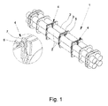
- Fig. 1 shows an embodiment of a Coriolis mass flowmeter 1 with four measuring tubes 2.
- vibration generator 3 and vibration sensor 4 are connected to the measuring tubes 2.
- both the vibration sensor 4 and the vibration generator 3 each comprise a permanent magnet 6 and a coil 7.
- vibrations can be transmitted to the measuring tubes 2 by means of electrical means or vibrations of the measuring tubes 2 can be detected.
- the vibration sensor 4 are attached to the inlet and outlet side of the measuring tube 2. Without flow, the signals of the two vibration sensor 4 are substantially in phase.
- the vibration behavior of the measuring tube 2 depends not only on the excitation of the measuring tube 2, but also of the measuring tube temperature, which affects the rigidity of the measuring tube, a possible structural change of the measuring tube 2, for example by corrosion, or by the temperature dependence
- the vibration behavior of the measuring tube 2 depends not only on the excitation of the measuring tube 2, but also of the measuring tube temperature, which affects the rigidity of the measuring tube, a possible structural change of the measuring tube 2, for example by corrosion, or by the temperature dependence
- there is a desire to compensate for such temperature effects be it in the determination of physical parameters of the Coriolis mass flowmeter, physical state variables or derived state variables D, which have no immediate physical meaning but are nevertheless suitable for determining the condition and thus also a change in the state of the Coriolis mass flowmeter.
- Fig. 2 shows a qualitative representation of the coil impedance R against the measuring tube temperature T at steady state conditions.
- the stationary case ie at a constant measuring tube temperature, there is a linear relationship between the coil impedance R and the measuring tube temperature T.
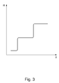
- FIG. 3 shows Fig. 3 a qualitative representation of the coil impedance R against the measuring tube temperature T at thermally unsteady conditions, ie at variable measuring tube temperature.
- a change in the measuring tube temperature T (horizontal) leads to a significantly delayed response of the coil impedance R.
- This delayed tracking leads to typical hysteresis effects both during a temperature increase and during cooling processes.
- the proposed method of operation of a Coriolis flowmeter counteracts this circumstance by correcting the temperature-dependent state variable D starting from the temperature of the measuring tube 2 with the specific impedance of the coil, since in the impedance of the coil 7 information about the temperature of the adjacent permanent magnet 6 is included.
- Fig. 4 shows the schematic sequence of an embodiment of the method described above.
- the vibration generator 3 attached to the Coriolis mass flowmeter 1 excites the measuring tubes 2 to vibrate in a first step 101.
- the vibrations are subsequently detected by the vibration sensors 4 in step 102.
- the temperature of the measuring tubes is determined in step 103.
- the electrical impedance of the coil is determined 104.
- the order of these steps is not on the in the Fig. 4 set order. Vibration detection, measuring tube temperature determination and the determination of the coil impedance can be carried out successively or simultaneously.
- the recorded signals are forwarded to an evaluation device 5.
- the evaluation device 5 calculates one or more state variables D of the Coriolis mass flowmeter 1 with the recorded signals. Since the preferred state variables which can provide information about the current state of the Coriolis mass flowmeter 1 are partly temperature-dependent, the measuring tube temperature is used for the determination of the actual temperature-dependent state value used.
- the resulting Meßrohrschwingungen are also dependent on the applied by the energization of the vibrator exciting force.
- the generated force is again dependent on the temperature of the permanent magnet 6, since its magnetization is temperature-dependent.
- the context of the in the Fig. 2 and Fig. 3 becomes clear to determine the magnet temperature or a value related to the magnet temperature or to the closer coil.
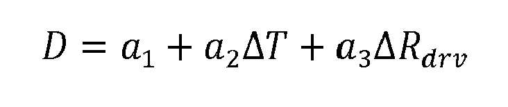
- the coil 7 has a known temperature coefficient.
- ⁇ T is the change in the measuring tube temperature
- ⁇ R drv the change in electrical impedance of the coil.
- the coefficients a 1 to a 3 represent empirical parameters for the Coriolis mass flowmeter.
- Fig. 5 shows an extension of the procedure.
- oscillations are generated in step 101 and then recorded 102.
- the measuring tube temperature T and the electrical coil impedance R are determined, so that the evaluation device 5 can calculate state variables from the determined values.
- a reference value D ref of the state variable D is determined before the start-up of the Coriolis mass flowmeter 1 in the installed situation.
- values D mess of the state variable D are continuously calculated from the recorded signals.
- the calculated values D mess are also continuously compared 108 with the previously determined reference value D ref .
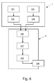
- Fig. 6 shows a further embodiment of the method for operating a Coriolis mass flowmeter 1.
- the operator of the Coriolis mass flowmeter 1 can recognize that the state of the measuring device has changed and, if necessary, take steps to restore the desired state.
Landscapes
- Physics & Mathematics (AREA)
- Fluid Mechanics (AREA)
- General Physics & Mathematics (AREA)
- Engineering & Computer Science (AREA)
- Signal Processing (AREA)
- Measuring Volume Flow (AREA)
Abstract
Beschrieben und dargestellt ist ein Verfahren zum Betreiben eines Coriolis-Massedurchflussmessgeräts (1), wobei das Coriolis-Massedurchflussmessgerät (1) wenigstens ein Messrohr (2), wenigstens einen Schwingungserzeuger (3), wenigstens zwei Schwingungsaufnehmer (4) und wenigstens eine Auswerteeinrichtung (5) aufweist, wobei die Schwingungsaufnehmer (4) und/oder der Schwingungserzeuger (3) jeweils mindestens einen Permanentmagneten (6) und jeweils mindestens eine Spule (7) umfassen, wobei der Schwingungserzeuger (3) das Messrohr (2) zu Schwingungen anregt, wobei die Schwingungsaufnehmer (4) die Schwingungen des Messrohrs (2) erfassen, wobei die Temperatur des Messrohrs (2) bestimmt wird und wobei die Auswerteeinrichtung (5) die erfassten Schwingungssignale verarbeitet und Zustandsgrößen des Coriolis-Massedurchflussmessgeräts (1) bestimmt. Ein Verfahren zum Betreiben eines Coriolis-Massedurchflussmessgeräts (1), das bei der Bestimmung von Zustandswerten eine höhere Genauigkeit aufweist, wird dadurch realisiert, dass die elektrische Impedanz der Spule (7) des Schwingungserzeugers (3) und/oder die elektrische Impedanz wenigstens einer Spule (7) der Schwingungsaufnehmer (4) ermittelt wird und dass die Auswerteeinrichtung (5) mindestens eine temperaturabhängige Zustandsgröße D berechnet, wobei die temperaturabhängige Zustandsgröße D ausgehend von der Temperatur des Messrohrs (2) mit der bestimmten Impedanz der Spule (7) korrigiert wird.Described and illustrated is a method for operating a Coriolis mass flowmeter (1), wherein the Coriolis mass flowmeter (1) at least one measuring tube (2), at least one vibration generator (3), at least two vibration sensor (4) and at least one evaluation device (5 ), wherein the vibration sensor (4) and / or the vibration generator (3) each comprise at least one permanent magnet (6) and at least one coil (7), wherein the vibration generator (3) excites the measuring tube (2) to oscillate, the vibration sensors (4) detect the vibrations of the measuring tube (2), wherein the temperature of the measuring tube (2) is determined and wherein the evaluation device (5) processes the detected vibration signals and determines state variables of the Coriolis mass flowmeter (1). A method for operating a Coriolis mass flowmeter (1), which has a higher accuracy in the determination of state values, is realized in that the electrical impedance of the coil (7) of the vibrator (3) and / or the electrical impedance of at least one coil (7) the vibration sensor (4) is determined and that the evaluation device (5) calculates at least one temperature-dependent state variable D, the temperature-dependent state variable D starting from the temperature of the measuring tube (2) is corrected with the specific impedance of the coil (7).
Description
Die Erfindung betrifft ein Verfahren zum Betreiben eines Coriolis-Massedurchflussmessgeräts, wobei das Coriolis-Massedurchflussmessgerät wenigstens ein Messrohr, wenigstens einen Schwingungserzeuger, wenigstens zwei Schwingungsaufnehmer und wenigstens eine Auswerteeinrichtung aufweist, wobei die Schwingungsaufnehmer und/oder der Schwingungserzeuger jeweils mindestens einen Permanentmagneten und jeweils mindestens eine Spule umfassen, wobei der Schwingungserzeuger das Messrohr zu Schwingungen anregt, wobei die Schwingungsaufnehmer die Schwingungen des Messrohrs erfassen, wobei die Temperatur des Messrohrs bestimmt wird und wobei die Auswerteeinrichtung die erfassten Schwingungssignale verarbeitet und Zustandsgrößen des Coriolis-Massedurchflussmessgeräts bestimmt.The invention relates to a method for operating a Coriolis mass flowmeter, wherein the Coriolis mass flowmeter has at least one measuring tube, at least one vibration generator, at least two vibration sensors and at least one evaluation device, wherein the vibration sensor and / or the vibration generator in each case at least one permanent magnet and at least one Coil comprise, wherein the vibration generator excites the measuring tube to vibrations, wherein the vibration sensor detect the vibrations of the measuring tube, wherein the temperature of the measuring tube is determined and wherein the evaluation device processes the detected vibration signals and determines state variables of the Coriolis mass flowmeter.
Coriolis-Massedurchflussmessgeräte sind im Stand der Technik in einer Vielzahl von Ausgestaltungen bekannt. Massedurchflussmessgeräte, die nach dem Coriolis-Prinzip arbeiten, weisen wenigstens einen Schwingungserzeuger, mit dem das Messrohr zur Schwingung angeregt wird - oder ggf. auch mehrere Messrohre zur Schwingung angeregt werden -, sowie wenigstens zwei Schwingungsaufnehmer, mit denen die erzielte Schwingung oder die erzielten Schwingungen des Messrohrs erfasst werden, auf. Die Schwingungsaufnehmer sind ein- und auslaufseitig an dem Messrohr befestigt. Wird das Messrohr in Schwingung versetzt, ergeben sich, für den Fall, dass ein massebehaftetes Medium durch das Messrohr fließt, ein- und auslaufseitig gegenläufig beeinflusste Schwingungsanteile, die von den Schwingungsaufnehmern erfasst werden. Ohne Durchfluss sind die Signale der beiden Schwingungsaufnehmer im Idealfall phasengleich. Der Grund für die mit zunehmendem Massedurchfluss ein- und auslaufseitig resultierenden zunehmenden unterschiedlichen Schwingungsanteile sind ein- und auslaufseitig unterschiedlich gerichtete Corioliskräfte auf das strömende Medium.Coriolis mass flowmeters are known in the art in a variety of configurations. Mass flowmeters that operate according to the Coriolis principle have at least one vibration generator with which the measuring tube is excited to vibrate - or possibly several measuring tubes are excited to vibrate - and at least two vibration sensors with which the vibration obtained or the vibrations obtained of the measuring tube are detected on. The vibration sensors are mounted on the inlet and outlet side of the measuring tube. If the measuring tube is set in oscillation, in the event that a medium-laden medium flows through the measuring tube, there are oscillation components which are influenced in opposite directions on the inlet and outlet sides and which are detected by the vibration sensors. Without flow, the signals of the two vibration sensors are ideally in phase. The reason for the increasing and decreasing mass flow resulting increasing different vibration components on the inlet and outlet side are differently directed Coriolis forces on the flowing medium.
Schwingungserzeuger von Coriolis-Massedurchflussmessgeräten der vorgenannten Art umfassen eine Spule und einen Permanentmagneten. Der Permanentmagnet ist jedenfalls so im Einflussbereich der Spule angeordnet, dass das bei Bestromung der Spule erzeugte Magnetfeld mit dem Magnetfeld des Permanentmagneten wechselwirkt und entsprechende Kräfte auf Spule und Permanentmagneten wirken. Die Höhe des elektrischen Stroms, mit dem die Spule beaufschlagt wird, ist dabei maßgebend für die Kraft, die vom Schwingungserzeuger auf das Messrohr übertragen wird und die das Messrohr zu Schwingungen anregt; die Bestromung der Spule erfolgt im Regelfall harmonisch und damit auch die Kraftbeaufschlagung des Messrohrs. Wenn das Coriolis-Massedurchflussmessgerät als ein dynamisches System mit der Eingangsgröße Anregungskraft und der Ausgangsgröße Messrohrauslenkung - oder eine davon zeitlich abgeleitete Größe wie die Messrohrgeschwindigkeit - betrachtet wird, dann liegen bei bekannter Anregungskraft und messtechnisch erfasster Messrohrgeschwindigkeit Informationen zur Identifikation des Übertragungsverhaltens des dynamischen Systems Coriolis-Massedurchflussmessgerät vor. Wenn die Identifikation auf Grundlage eines mathematischen Modells erfolgt, ist es möglich, in dem Modell verwendete Parameter zu bestimmen, wie beispielsweise die Federsteifigkeit des Messrohrs, die Dämpfung des Messrohrs und die schwingende Gesamtmasse (
Die physikalischen Parameter und damit auch die funktionalen Zusammenhänge unterliegen jedoch oft weiteren Einflüssen, die im Idealfall berücksichtigt werden sollten, um genaue Messergebnisse zu erhalten. So ist beispielsweise die Steifigkeit des Messrohrs unter anderem temperaturabhängig. Aus dem Stand der Technik sind der Anmelderin Verfahren bekannt, bei denen die Messrohrtemperatur durch einen auf dem Messrohr angebrachten Sensor gemessen wird, um beispielsweise die Temperaturabhängigkeit der Federsteifigkeit des Messrohrs berücksichtigen zu können.However, the physical parameters and thus the functional relationships are often subject to further influences, which should ideally be taken into account in order to obtain accurate measurement results. For example, the rigidity of the measuring tube is, among other things, temperature-dependent. From the prior art, the Applicant methods are known in which the measuring tube temperature is measured by a mounted on the measuring tube sensor, for example, to take into account the temperature dependence of the spring stiffness of the measuring tube.
Der Erfindung liegt daher die Aufgabe zugrunde, ein Verfahren zum Betreiben eines Coriolis-Massedurchflussmessgeräts anzugeben, das bei der Bestimmung von Zustandsgrößen bzw. von Werten für Zustandsgrößen eine höhere Genauigkeit aufweist.The invention is therefore based on the object to provide a method for operating a Coriolis mass flowmeter, which has a higher accuracy in the determination of state variables or values for state variables.
Die zuvor hergeleitete Aufgabe ist bei einem gattungsgemäßen Verfahren zum Betreiben eines Coriolis-Massedurchflussmessgeräts dadurch gelöst, dass die elektrische Impedanz der Spule des Schwingungserzeugers und/oder die elektrische Impedanz wenigstens einer Spule der Schwingungsaufnehmer ermittelt wird und dass die Auswerteeinrichtung mindestens eine temperaturabhängige Zustandsgröße D berechnet, wobei die temperaturabhängige Zustandsgröße D ausgehend von der Temperatur des Messrohrs mit der bestimmten Impedanz der Spule korrigiert wird.In a generic method for operating a Coriolis mass flowmeter, the previously derived object is achieved in that the electrical impedance of the coil of the vibration generator and / or the electrical impedance of at least one coil of the vibration sensor are determined is and that the evaluation device calculates at least one temperature-dependent state variable D, wherein the temperature-dependent state variable D is corrected starting from the temperature of the measuring tube with the specific impedance of the coil.
Bei der Zustandsgröße D kann es sich um eine technisch-physikalische Größe des Coriolis-Massedurchflussmessgeräts handeln, es kann sich aber auch um eine fiktive charakteristische Größen handeln, die beispielsweise zur Überwachung eines Gutzustandes des jeweiligen Coriolis-Massedurchflussmessgerätes geeignet ist; eine solche fiktive charakteristische Größe könnte in Zusammenhang mit der Federsteifigkeit des Messrohrs stehen, ohne die Federsteifigkeit selbst exakt abzubilden.The state variable D may be a technical-physical quantity of the Coriolis mass flowmeter, but it may also be a fictitious characteristic variable which is suitable, for example, for monitoring a good state of the respective Coriolis mass flowmeter; such a fictitious characteristic size could be related to the spring stiffness of the measuring tube, without exactly mapping the spring stiffness itself.
Das erfindungsgemäße Verfahren ermöglicht die Kompensation von Temperatureffekten, die insbesondere in Zusammenhang mit der Temperaturabhängigkeit der Magnetisierung der hier verwendeten Permanentmagneten stehen. Für kleine Temperaturen, also Temperaturen unterhalb der Curie-Temperatur, ist beispielsweise der folgende gleichungsmäßige Zusammenhang nach Bloch bekannt: ![]()
![]()
Bei dem erfindungsgemäßen Verfahren ist es nicht notwendig, auf kompliziertem Weg die Magnettemperatur zu messen. Der Spulenwiderstand, bzw. die elektrische Impedanz der Spule liefert einen Zusammenhang, der eine Kompensation des Einflusses der Magnettemperatur erlaubt. Vorteilhaft ist hier, dass die Spule, deren Impedanz erfasst wird, funktionsnotwendig in unmittelbarer Umgebung des ihr zugeordneten Permanentmagneten angeordnet ist und demzufolge die Temperatur der Spule in guter Näherung der Temperatur des Permanentmagneten entspricht. Da die Impedanz bzw. der ohmsche Widerstand der Spule im Regelfall ebenfalls temperaturveränderlich sind, ist die erfasste Impedanz der Spule ein zuverlässiger Indikator für die Temperatur der Spule und für die Temperatur des in unmittelbarer Nähe vorgesehenen Permanentmagneten.In the method according to the invention, it is not necessary to measure the magnet temperature in a complicated way. The coil resistance, or the electrical impedance of the coil provides a relationship that allows compensation of the influence of the magnet temperature. It is advantageous here that the coil whose impedance is detected, is functionally necessary in the immediate vicinity of its associated permanent magnet is arranged and Consequently, the temperature of the coil corresponds to a good approximation of the temperature of the permanent magnet. Since the impedance or the ohmic resistance of the coil are usually also variable in temperature, the detected impedance of the coil is a reliable indicator of the temperature of the coil and the temperature of the provided in the immediate vicinity permanent magnet.
Für eine Erhöhung der Genauigkeit ist in einer erweiterten Ausgestaltung des Verfahrens vorgesehen, dass die Korrektur der Zustandsgröße D auf Basis wenigstens eines bekannten Temperaturkoeffizienten zur Beschreibung der Temperaturabhängigkeit der Spule erfolgt. Durch Nutzung dieses Sachverhalts kann unmittelbar durch Messung der Spulenimpedanz oder des Ohmschen Widerstands der Spule auf die Temperatur der Spule geschlossen werden. So ist durch die Bestimmung der Spulenimpedanz eine genauere Bestimmung der Spulentemperatur bzw. der Temperatur des Permanentmagneten und damit eine bessere Kompensation von Effekten möglich, die in Zusammenhang mit der Magnettemperatur stehen.In order to increase the accuracy, it is provided in an expanded embodiment of the method that the correction of the state variable D takes place on the basis of at least one known temperature coefficient for describing the temperature dependence of the coil. By utilizing this fact, it is possible to immediately deduce the temperature of the coil by measuring the coil impedance or the ohmic resistance of the coil. Thus, by determining the coil impedance a more accurate determination of the coil temperature or the temperature of the permanent magnet and thus a better compensation of effects are possible, which are related to the magnet temperature.
Eine weitere Ausgestaltung des erfindungsgemäßen Verfahrens sieht vor, dass ein Referenzwert Dref der Zustandsgröße D vor Inbetriebnahme des Coriolis-Massedurchflussmessgeräts im laufenden Prozess bestimmt wird. Vor Inbetriebnahme kann bedeuten, dass das Gerät bereits ab Werk mit einem Referenzwert kalibriert wird. Dieser kann im Gerät vor Auslieferung gespeichert sein. Ebenso ist es denkbar, dass der Referenzwert in Einbausituation im Prozess vor Ort bestimmt wird, wenn das Coriolis-Massedurchflussmessgerät bereits in den Prozess integriert, jedoch noch nicht in Betrieb genommen wurde. Außerdem ist es sinnvoll, dass das Gerät auch bei einem Wechsel der Prozessbedingungen neu kalibriert wird, d. h. ein neuer Referenzwert berechnet werden kann. Wechselnde Prozessbedingungen können bedingt sein durch einen Ausbau des Geräts oder die Integration des Geräts in einen neuen Prozess oder beispielsweise auch durch Änderung des durchströmenden Mediums.A further embodiment of the method according to the invention provides that a reference value D ref of the state variable D is determined before the start-up of the Coriolis mass flowmeter in the ongoing process. Before commissioning, it may mean that the device is already calibrated at the factory with a reference value. This can be stored in the device before delivery. It is also conceivable that the reference value in the installation situation in the process is determined on site if the Coriolis mass flowmeter has already been integrated into the process but has not yet been put into operation. In addition, it makes sense that the device is recalibrated even if the process conditions change, ie a new reference value can be calculated. Changing process conditions may be due to an expansion of the device or the integration of the device in a new process or, for example, by changing the medium flowing through.
In einer erweiterten Ausgestaltung des Verfahrens ist vorgesehen, dass der Referenzwert Dref mit einem im Betrieb bestimmten Wert Dmess der Zustandsgröße D verglichen wird. Der im Betrieb bestimmte Wert Dmess kann in beliebigen Intervallen oder kontinuierlich bestimmt werden. Der fortlaufende Vergleich mit dem Referenzwert Dref ermöglicht es Aussagen darüber zu treffen, inwieweit der aktuelle Zustand des Coriolis-Massedurchflussmessgeräts dem Ursprungszustand zum Zeitpunkt der Referenzwertbestimmung entspricht.In an expanded embodiment of the method, it is provided that the reference value D ref is compared with a value D mess of the state variable D determined during operation. The operational value D mess can be determined at any interval or continuously. The ongoing Comparison with the reference value D ref makes it possible to make statements as to how far the current state of the Coriolis mass flowmeter corresponds to the original state at the time of the reference value determination.
In einer weiteren Ausgestaltung des Verfahrens ist vorgesehen, dass bei Überschreiten einer zuvor definierten Abweichung E des Referenzwertes Dref von dem im Betrieb ermittelten Wert Dmess der Zustandsgröße D ein Signal von der Auswerteeinrichtung ausgegeben wird. Bei dem Signal kann es sich schlicht um das Setzen eines Flags handeln, also beispielsweise das Setzen eines Bits in einer Speicherzelle innerhalb der Elektronik des Coriolis-Massedurchflussmessgeräts. Das Signal kann aber auch elektrisch, akustisch oder mittels einer Visualisierung über eine Schnittstelle des Coriolis-Massedurchflussmessgeräts ausgegeben werden. Insbesondere können die Signale nachfolgend auch in einer übergeordneten Leitwarte ausgegeben werden, die dem Betreiber verdeutlichen, dass sich der Zustand des Messgeräts verändert hat, beispielsweise ein Gutzustand nicht mehr vorliegt.In a further embodiment of the method, it is provided that when a predefined deviation E of the reference value D ref is exceeded, a signal from the evaluation device is output from the value D mess of the state variable D determined during operation. The signal may simply be the setting of a flag, such as setting a bit in a memory cell within the electronics of the Coriolis mass flowmeter. The signal can also be output electrically, acoustically or by means of a visualization via an interface of the Coriolis mass flowmeter. In particular, the signals can subsequently also be output in a higher-level control room, which clarify to the operator that the state of the measuring device has changed, for example, a good state is no longer present.
Die Berechnung der temperaturabhängigen Zustandsgröße D und damit auch der Werte Dref und/oder Dmess der Zustandsgröße D erfolgt bevorzugt in Abhängigkeit von der Messrohrtemperatur T und der erfassten Spulenimpedanz Rdrv, also nach einem Zusammenhang der Form D = f(T, Rdrv). Vorzugsweise erfolgt die Bestimmung jeweils bezogen auf einen Referenz-Temperaturwert T0 und einen Referenz-Impedanzwert Rdrv,0., dann also nach einem Zusammenhang der Form D = f(ΔT, ΔRdrv ).The calculation of the temperature-dependent state variable D and thus also the values D ref and / or D mess of the state variable D preferably takes place as a function of the measuring tube temperature T and the detected coil impedance R drv , ie according to a relationship of the form D = f (T, R drv ). Preferably, the determination is in each case based on a reference temperature value T 0 and a reference impedance value R drv, 0. , Then so for a connection of the form D = f (Δ T Δ R drv).
Die Berechnung der temperaturabhängigen Werte Dref und/oder Dmess der Zustandsgröße D werden in einer Ausgestaltung des erfindungsgemäßen Verfahrens unter Verwendung des folgenden Zusammenhangs bestimmt: ![]()
![]()
![]()
![]()
Die aus dem Schwingverhalten abgeleiteten Zustandsgrößen geben Auskunft auf die strukturelle Beschaffenheit des Coriolis-Massedurchflussmessgeräts. Das Schwingverhalten eines Coriolis-Massedurchflussmessgeräts kann mathematisch grundsätzlich durch eine Lagrange-Gleichung 2. Art beschrieben werden. Dabei stellt eine Schwingung in der ersten Eigenform, also einer Anregung des Messrohrs zu Schwingungen bei größtmöglicher Amplitude, wobei eine Deformation oder sogar eine Zerstörung des Messrohrs vermieden wird, eine gleichphasige, translatorische Bewegung der Massen des Messrohrs dar. Eine Rotation der Massen um den Mittelpunkt des Messrohrs entspricht einer Schwingung in der zweiten Eigenform. Alle betrachteten Eigenformen können in einem Differentialgleichungssystem dargestellt werden, wobei die entscheidenden Faktoren die Trägheitsmatrix, die Dämpfungsmatrix und die Steifigkeitsmatrix sind.The state variables derived from the vibration behavior provide information on the structural nature of the Coriolis mass flowmeter. The oscillation behavior of a Coriolis mass flowmeter can be described mathematically in principle by a Lagrangian equation of the 2nd kind. In this case, an oscillation in the first eigenmode, ie an excitation of the measuring tube to oscillations with the greatest possible amplitude, whereby deformation or even destruction of the measuring tube is avoided, represents an in-phase, translational movement of the masses of the measuring tube. A rotation of the masses around the center of the measuring tube corresponds to a vibration in the second eigenform. All considered eigenmodes can be represented in a system of differential equations, where the decisive factors are the inertial matrix, the damping matrix and the stiffness matrix.
Daher ist es in einer Ausgestaltung des erfindungsgemäßen Verfahrens zum Betreiben eines Coriolis-Massedurchflussmessgerät besonders vorteilhaft, dass die Zustandsgrößen D in Abhängigkeit von der Steifigkeit des Messrohrs berechnet werden. Eine Aussage über die Steifigkeit ergibt eine gute Näherung zur Lebensdauer und Funktionalität des Coriolis-Massedurchflussmessgeräts.Therefore, in one embodiment of the method according to the invention for operating a Coriolis mass flowmeter, it is particularly advantageous that the state variables D are calculated as a function of the rigidity of the measuring tube. A statement about stiffness gives a good approximation to the life and functionality of the Coriolis mass flowmeter.
Ebenso ist es in einer weiteren Ausgestaltung des erfindungsgemäßen Verfahrens vorteilhaft, dass die Zustandsgrößen in Abhängigkeit von der Dämpfung des Messrohrs berechnet werden.Likewise, it is advantageous in a further embodiment of the method according to the invention that the state variables are calculated as a function of the attenuation of the measuring tube.
In einer weiteren Ausgestaltung des Verfahrens ist entsprechend vorgesehen, dass die Zustandsgrößen in Abhängigkeit von der Masse des Messrohrs berechnet werden.In a further embodiment of the method, it is accordingly provided that the state variables are calculated as a function of the mass of the measuring tube.
Bei der Berechnung der Zustandsgrößen kommt es darauf an, inwieweit das Messrohr des Coriolis-Massedurchflussmessgeräts zu Schwingungen bzw. in welcher Eigenform es zu Schwingungen angeregt wird. Für die Identifikation einer Zustandsgröße in Abhängigkeit von der Steifigkeit des Messrohrs wird die Schwingung vorzugsweise im "drive mode" erzeugt, was einer Schwingung in der ersten Eigenform entspricht.When calculating the state variables, it depends on the extent to which the measuring tube of the Coriolis mass flowmeter vibrates or in which form it is excited to vibrate. For the identification of a state variable as a function of the rigidity of the measuring tube is the oscillation is preferably generated in the "drive mode", which corresponds to an oscillation in the first eigenform.
Im Einzelnen gibt nun eine Vielzahl von Möglichkeiten das erfindungsgemäße Verfahren zum Betreiben eines Coriolis-Massedurchflussmessgeräts auszugestalten und weiterzubilden. Dazu wird verwiesen sowohl auf die dem Patentanspruch 1 nachgeordneten Patentansprüche als auch auf die nachfolgende Beschreibung von bevorzugten Ausführungsbeispielen in Verbindung mit der Zeichnung. In der Zeichnung zeigen:
- Fig. 1
- ein Ausführungsbeispiel eines Coriolis-Massedurchflussmessgeräts in perspektivischer Ansicht,
- Fig. 2
- den schematischen Verlauf der Abhängigkeit der elektrischen Impedanz der Spule von der Messrohrtemperatur bei stationären Bedingungen,
- Fig. 3
- den schematischen Verlauf der Abhängigkeit der elektrischen Impedanz der Spule von der Messrohrtemperatur bei instationären Bedingungen,
- Fig. 4
- den schematischen Ablauf einer Ausgestaltung des Verfahrens zum Betreiben eines Coriolis-Massedurchflussmessgeräts,
- Fig. 5
- den schematischen Ablauf einer erweiterten Ausgestaltung des Verfahrens zum Betreiben eines Coriolis-Massedurchflussmessgeräts,
- Fig. 6
- den schematischen Ablauf einer weiteren Ausgestaltung des Verfahrens zum Betreiben eines Coriolis-Massedurchflussmessgeräts.
- Fig. 1
- An embodiment of a Coriolis mass flowmeter in perspective view,
- Fig. 2
- the schematic course of the dependence of the electrical impedance of the coil on the measuring tube temperature at stationary conditions,
- Fig. 3
- the schematic course of the dependence of the electrical impedance of the coil on the measuring tube temperature under unsteady conditions,
- Fig. 4
- the schematic sequence of an embodiment of the method for operating a Coriolis mass flowmeter,
- Fig. 5
- the schematic sequence of an extended embodiment of the method for operating a Coriolis mass flowmeter,
- Fig. 6
- the schematic flow of another embodiment of the method for operating a Coriolis mass flowmeter.
Die Schwingverhalten des Messrohrs 2 hängt allerdings nicht nur von der Anregung des Messrohrs 2 ab, sondern auch von der Messrohrtemperatur, die sich auf die Steifigkeit des Messrohrs auswirkt, von einer möglichen strukturellen Veränderung des Messrohrs 2, beispielsweise durch Korrosion, oder auch von der Temperaturabhängigkeit des Übertragungsverhaltens des Schwingungserzeugers 3. Bei dem Betrieb eines Coriolis-Massedurchflussmessgeräts besteht deshalb der Wunsch, auch derartige Temperatureffekte zu kompensieren, sei es bei der Bestimmung physikalischer Parameter des Coriolis-Massedurchflussmessgeräts, bei physikalischen Zustandsgrößen oder bei abgeleiteten Zustandsgrößen D, die keine unmittelbare physikalische Bedeutung haben müssen, gleichwohl aber geeignet sind, den Zustand und damit auch eine Veränderung des Zustands des Coriolis-Massedurchflussmessgeräts zu ermitteln.However, the vibration behavior of the measuring
Im Gegensatz dazu zeigt
Die aufgenommenen Signale werden an eine Auswerteeinrichtung 5 weitergeleitet. Die Auswerteeinrichtung 5 berechnet mit den aufgenommenen Signalen eine oder mehrere Zustandsgrößen D des Coriolis-Massedurchflussmessgeräts 1. Da die bevorzugten Zustandsgrößen, die eine Auskunft über die aktuelle Beschaffenheit des Coriolis-Massedurchflussmessgeräts 1 geben können, teilweise temperaturabhängig sind, wird die Messrohrtemperatur für die Bestimmung des tatsächlichen temperaturabhängigen Zustandswertes verwendet.The recorded signals are forwarded to an
Die resultierenden Messrohrschwingungen sind auch abhängig von der durch durch die Bestromung des Schwingungserzeugers aufgebrachten Anregungskraft. Die erzeugte Kraft ist wiederum abhängig von der Temperatur des Permanentmagneten 6, da dessen Magnetisierung temperaturabhängig ist. Insbesondere der Zusammenhang der in den ![]()
![]()

Claims (9)
dadurch gekennzeichnet,
dass die elektrische Impedanz der Spule (7) des Schwingungserzeugers (3) und/oder die elektrische Impedanz wenigstens einer Spule (7) der Schwingungsaufnehmer (4) ermittelt wird und dass die Auswerteeinrichtung (5) mindestens eine temperaturabhängige Zustandsgröße D berechnet, wobei die temperaturabhängige Zustandsgröße D ausgehend von der Temperatur des Messrohrs (2) mit der bestimmten Impedanz der Spule (7) korrigiert wird.Method for operating a Coriolis mass flowmeter (1), wherein the Coriolis mass flowmeter (1) at least one measuring tube (2), at least one vibration generator (3), at least two vibration sensor (4) and at least one evaluation device (5), wherein the Vibration sensor (4) and / or the vibration generator (3) each comprise at least one permanent magnet (6) and at least one coil (7), wherein the vibration generator (3) excites the measuring tube (2) to oscillate, wherein the vibration sensor (4) detecting the vibrations of the measuring tube (2), wherein the temperature of the measuring tube (2) is determined and wherein the evaluation device (5) processes the detected vibration signals and determines state variables of the Coriolis mass flowmeter (1),
characterized,
that the electrical impedance of the coil (7) of the vibration generator (3) and / or the electrical impedance of at least one coil (7) of the vibration sensor (4) is determined and that the evaluation device (5) calculates at least one temperature-dependent state variable D, wherein the temperature-dependent State variable D is corrected on the basis of the temperature of the measuring tube (2) with the specific impedance of the coil (7).
bestimmt wird, wobei Rdrv der elektrischen Impedanz der Spule (7), T der Messrohrtemperatur und
where R drv is the electrical impedance of the coil (7), T is the measuring tube temperature and
Applications Claiming Priority (1)
| Application Number | Priority Date | Filing Date | Title |
|---|---|---|---|
| DE102015100573.5A DE102015100573A1 (en) | 2015-01-15 | 2015-01-15 | Method of operating a Coriolis mass flowmeter |
Publications (2)
| Publication Number | Publication Date |
|---|---|
| EP3045877A1 true EP3045877A1 (en) | 2016-07-20 |
| EP3045877B1 EP3045877B1 (en) | 2018-09-26 |
Family
ID=54695625
Family Applications (1)
| Application Number | Title | Priority Date | Filing Date |
|---|---|---|---|
| EP15195810.5A Active EP3045877B1 (en) | 2015-01-15 | 2015-11-23 | Method for operating a coriolis mass flow measuring device |
Country Status (4)
| Country | Link |
|---|---|
| US (1) | US9513150B2 (en) |
| EP (1) | EP3045877B1 (en) |
| CN (1) | CN105806432B (en) |
| DE (1) | DE102015100573A1 (en) |
Families Citing this family (8)
| Publication number | Priority date | Publication date | Assignee | Title |
|---|---|---|---|---|
| DE102014105580A1 (en) * | 2014-04-17 | 2015-10-22 | Krohne Ag | Coriolis mass flowmeter |
| CN107764350B (en) * | 2016-08-18 | 2020-05-08 | 高准有限公司 | Mass flow measuring method and mass flow meter |
| CN109997018B (en) * | 2016-11-30 | 2021-11-30 | 高准公司 | Temperature compensation of test tones used in meter verification |
| DE102017102449A1 (en) * | 2017-02-08 | 2018-08-09 | Krohne Ag | Pressure measurement method for a Coriolis mass flowmeter and Coriolis mass flowmeter |
| US12044550B2 (en) * | 2018-05-23 | 2024-07-23 | Iee International Electronics & Engineering S.A. | Method of compensating temperature influence in capacitive measurements |
| DE102019122094B3 (en) * | 2019-08-16 | 2021-01-28 | Endress+Hauser Flowtec Ag | Method for calculating a quality of a measuring tube of a Coriolis measuring device and such a measuring device |
| DE102020130992A1 (en) * | 2020-11-24 | 2022-05-25 | Endress+Hauser Flowtec Ag | Method for determining a state of a Coriolis meter |
| DE102022129037A1 (en) | 2022-11-03 | 2024-05-08 | Krohne Messtechnik Gmbh | Procedure for testing a Coriolis mass flow meter |
Citations (7)
| Publication number | Priority date | Publication date | Assignee | Title |
|---|---|---|---|---|
| US5460049A (en) * | 1994-01-26 | 1995-10-24 | Instrumention Northwest, Inc. | Digitally-temperature-compensated strain-gauge pressure measuring apparatus |
| WO1998031990A1 (en) * | 1997-01-16 | 1998-07-23 | Direct Measurement Corporation | Signal processing and field proving methods and circuits for a coriolis mass flow meter |
| US20040221660A1 (en) * | 2003-05-05 | 2004-11-11 | Dutton Robert E. | Two-phase steam measurement system |
| DE102008059920A1 (en) | 2008-12-02 | 2010-07-01 | Krohne Meßtechnik GmbH & Co KG | Method for operating a resonance measuring system and related resonance measuring system |
| WO2012018323A1 (en) * | 2010-08-02 | 2012-02-09 | Micro Motion, Inc. | Method and apparatus for determining a temperature of a vibrating sensor component of a vibrating meter |
| WO2012067608A1 (en) * | 2010-11-16 | 2012-05-24 | Micro Motion, Inc. | Multiple temperature sensor system |
| DE102012011934A1 (en) | 2012-06-18 | 2013-12-19 | Krohne Messtechnik Gmbh | Method for operating a resonance measuring system and related resonance measuring system |
Family Cites Families (10)
| Publication number | Priority date | Publication date | Assignee | Title |
|---|---|---|---|---|
| US5231884A (en) * | 1991-07-11 | 1993-08-03 | Micro Motion, Inc. | Technique for substantially eliminating temperature induced measurement errors from a coriolis meter |
| DE4410160C1 (en) * | 1994-03-24 | 1995-10-05 | Ulrich Dipl Ing Elsen | Heat-resistant drive and measuring coil for oscillation pipe mass flowmeter |
| US5902931A (en) * | 1996-04-26 | 1999-05-11 | Murata Manufacturing Co., Ltd. | Vibration gyroscope |
| JP2002228453A (en) * | 2001-01-31 | 2002-08-14 | Murata Mfg Co Ltd | Oscillatory gyro and temperature drift adjusting method therefor |
| EP1724558A1 (en) * | 2005-05-18 | 2006-11-22 | Endress + Hauser Flowtec AG | Coriolis mass flow/density measuring devices and method for compensating measurement errors in such devices |
| JP2008064544A (en) * | 2006-09-06 | 2008-03-21 | Tokiko Techno Kk | Oscillation-type measuring apparatus |
| US7801694B1 (en) * | 2007-09-27 | 2010-09-21 | Watson Industries, Inc. | Gyroscope with temperature compensation |
| JP5086814B2 (en) * | 2008-01-07 | 2012-11-28 | 株式会社キーエンス | Flowmeter |
| US9207212B2 (en) | 2012-06-18 | 2015-12-08 | Krohne Messtechnik Gmbh | Method for operating a resonant measurement system |
| AU2014278632B2 (en) * | 2013-06-14 | 2016-10-20 | Micro Motion, Inc. | Vibratory flowmeter and method for meter verification |
-
2015
- 2015-01-15 DE DE102015100573.5A patent/DE102015100573A1/en not_active Withdrawn
- 2015-11-23 EP EP15195810.5A patent/EP3045877B1/en active Active
- 2015-12-09 US US14/963,567 patent/US9513150B2/en active Active
- 2015-12-10 CN CN201510910132.2A patent/CN105806432B/en active Active
Patent Citations (7)
| Publication number | Priority date | Publication date | Assignee | Title |
|---|---|---|---|---|
| US5460049A (en) * | 1994-01-26 | 1995-10-24 | Instrumention Northwest, Inc. | Digitally-temperature-compensated strain-gauge pressure measuring apparatus |
| WO1998031990A1 (en) * | 1997-01-16 | 1998-07-23 | Direct Measurement Corporation | Signal processing and field proving methods and circuits for a coriolis mass flow meter |
| US20040221660A1 (en) * | 2003-05-05 | 2004-11-11 | Dutton Robert E. | Two-phase steam measurement system |
| DE102008059920A1 (en) | 2008-12-02 | 2010-07-01 | Krohne Meßtechnik GmbH & Co KG | Method for operating a resonance measuring system and related resonance measuring system |
| WO2012018323A1 (en) * | 2010-08-02 | 2012-02-09 | Micro Motion, Inc. | Method and apparatus for determining a temperature of a vibrating sensor component of a vibrating meter |
| WO2012067608A1 (en) * | 2010-11-16 | 2012-05-24 | Micro Motion, Inc. | Multiple temperature sensor system |
| DE102012011934A1 (en) | 2012-06-18 | 2013-12-19 | Krohne Messtechnik Gmbh | Method for operating a resonance measuring system and related resonance measuring system |
Also Published As
| Publication number | Publication date |
|---|---|
| CN105806432A (en) | 2016-07-27 |
| DE102015100573A1 (en) | 2016-07-21 |
| US20160209257A1 (en) | 2016-07-21 |
| US9513150B2 (en) | 2016-12-06 |
| CN105806432B (en) | 2019-09-27 |
| EP3045877B1 (en) | 2018-09-26 |
Similar Documents
| Publication | Publication Date | Title |
|---|---|---|
| EP3045877B1 (en) | Method for operating a coriolis mass flow measuring device | |
| EP2196780B1 (en) | Method for operating a resonance measuring system and resonance measuring system | |
| EP1208359A2 (en) | Mass flow rate measuring device | |
| EP2677284B1 (en) | Method for operating a resonance measuring system and corresponding resonance measuring system | |
| DE102008046891A1 (en) | Measuring device of the vibration type | |
| DE102012017797A1 (en) | Flowmeter | |
| EP3256822B1 (en) | Device for determining and/or monitoring at least one process variable for a medium and corresponding method | |
| DE102019124709A1 (en) | Method for operating a measuring device with at least one oscillator and measuring device for carrying out the method | |
| EP2702370B1 (en) | Method for operating a resonance measuring system | |
| WO2012031842A1 (en) | Method for detecting a stoppage in a coriolis flow meter | |
| EP3196605A1 (en) | Method for operating a coriolis mass flow meter and coriolis mass flow meter | |
| EP2884244B1 (en) | Method for operating a coriolis mass flowmeter | |
| EP3628983B1 (en) | Method for determining the gas content in a medium flowing through a coriolis mass flow meter and coriolis mass flow meter | |
| EP3714253A1 (en) | Method for signalling a standard frequency of a density meter which has at least one vibratable measurement tube for conducting a medium | |
| DE102007028209A1 (en) | Method for measuring and / or monitoring a flow parameter and corresponding device | |
| EP3361222B1 (en) | Method for pressure measurement with a coriolis flow meter and coriolis flow meter | |
| EP3208598B1 (en) | Method for operating a coriolis mass flow measuring device | |
| EP3196603B1 (en) | Method for operating a coriolis mass flow meter and related coriolis mass flow meter | |
| DE102019123368A1 (en) | Method and measuring device for determining the viscosity of a medium | |
| WO2020259940A1 (en) | Method for ascertaining a physical parameter of a charged liquid | |
| EP4014013B1 (en) | Method for calculating a quality of a measuring tube of a coriolis measuring device and such a measuring device | |
| EP3196604B1 (en) | Method for operating a coriolis mass flow meter and related coriolis mass flow meter | |
| EP1711391B1 (en) | Method and device for determining a time average of a pulse width-modulated current of an electric motor | |
| DE102007024276A1 (en) | Method for measuring and monitoring flow parameter of medium, involves exciting measuring tube to mechanical vibrations by one converter element according to one excitation signal during one measurement | |
| DE102010040895A1 (en) | Device for measuring fluid flow in fluid channel, directs fluid flow vertical to direction of free and flat ends of bending element via longitudinal extent of bending element |
Legal Events
| Date | Code | Title | Description |
|---|---|---|---|
| PUAI | Public reference made under article 153(3) epc to a published international application that has entered the european phase |
Free format text: ORIGINAL CODE: 0009012 |
|
| AK | Designated contracting states |
Kind code of ref document: A1 Designated state(s): AL AT BE BG CH CY CZ DE DK EE ES FI FR GB GR HR HU IE IS IT LI LT LU LV MC MK MT NL NO PL PT RO RS SE SI SK SM TR |
|
| AX | Request for extension of the european patent |
Extension state: BA ME |
|
| 17P | Request for examination filed |
Effective date: 20160908 |
|
| RBV | Designated contracting states (corrected) |
Designated state(s): AL AT BE BG CH CY CZ DE DK EE ES FI FR GB GR HR HU IE IS IT LI LT LU LV MC MK MT NL NO PL PT RO RS SE SI SK SM TR |
|
| STAA | Information on the status of an ep patent application or granted ep patent |
Free format text: STATUS: EXAMINATION IS IN PROGRESS |
|
| 17Q | First examination report despatched |
Effective date: 20170516 |
|
| GRAP | Despatch of communication of intention to grant a patent |
Free format text: ORIGINAL CODE: EPIDOSNIGR1 |
|
| STAA | Information on the status of an ep patent application or granted ep patent |
Free format text: STATUS: GRANT OF PATENT IS INTENDED |
|
| GRAS | Grant fee paid |
Free format text: ORIGINAL CODE: EPIDOSNIGR3 |
|
| INTG | Intention to grant announced |
Effective date: 20180515 |
|
| GRAA | (expected) grant |
Free format text: ORIGINAL CODE: 0009210 |
|
| STAA | Information on the status of an ep patent application or granted ep patent |
Free format text: STATUS: THE PATENT HAS BEEN GRANTED |
|
| AK | Designated contracting states |
Kind code of ref document: B1 Designated state(s): AL AT BE BG CH CY CZ DE DK EE ES FI FR GB GR HR HU IE IS IT LI LT LU LV MC MK MT NL NO PL PT RO RS SE SI SK SM TR |
|
| REG | Reference to a national code |
Ref country code: GB Ref legal event code: FG4D Free format text: NOT ENGLISH |
|
| REG | Reference to a national code |
Ref country code: CH Ref legal event code: EP |
|
| REG | Reference to a national code |
Ref country code: AT Ref legal event code: REF Ref document number: 1046565 Country of ref document: AT Kind code of ref document: T Effective date: 20181015 |
|
| REG | Reference to a national code |
Ref country code: IE Ref legal event code: FG4D Free format text: LANGUAGE OF EP DOCUMENT: GERMAN |
|
| REG | Reference to a national code |
Ref country code: DE Ref legal event code: R096 Ref document number: 502015006060 Country of ref document: DE |
|
| REG | Reference to a national code |
Ref country code: NL Ref legal event code: MP Effective date: 20180926 |
|
| PG25 | Lapsed in a contracting state [announced via postgrant information from national office to epo] |
Ref country code: NO Free format text: LAPSE BECAUSE OF FAILURE TO SUBMIT A TRANSLATION OF THE DESCRIPTION OR TO PAY THE FEE WITHIN THE PRESCRIBED TIME-LIMIT Effective date: 20181226 Ref country code: GR Free format text: LAPSE BECAUSE OF FAILURE TO SUBMIT A TRANSLATION OF THE DESCRIPTION OR TO PAY THE FEE WITHIN THE PRESCRIBED TIME-LIMIT Effective date: 20181227 Ref country code: BG Free format text: LAPSE BECAUSE OF FAILURE TO SUBMIT A TRANSLATION OF THE DESCRIPTION OR TO PAY THE FEE WITHIN THE PRESCRIBED TIME-LIMIT Effective date: 20181226 Ref country code: SE Free format text: LAPSE BECAUSE OF FAILURE TO SUBMIT A TRANSLATION OF THE DESCRIPTION OR TO PAY THE FEE WITHIN THE PRESCRIBED TIME-LIMIT Effective date: 20180926 Ref country code: LT Free format text: LAPSE BECAUSE OF FAILURE TO SUBMIT A TRANSLATION OF THE DESCRIPTION OR TO PAY THE FEE WITHIN THE PRESCRIBED TIME-LIMIT Effective date: 20180926 Ref country code: RS Free format text: LAPSE BECAUSE OF FAILURE TO SUBMIT A TRANSLATION OF THE DESCRIPTION OR TO PAY THE FEE WITHIN THE PRESCRIBED TIME-LIMIT Effective date: 20180926 Ref country code: FI Free format text: LAPSE BECAUSE OF FAILURE TO SUBMIT A TRANSLATION OF THE DESCRIPTION OR TO PAY THE FEE WITHIN THE PRESCRIBED TIME-LIMIT Effective date: 20180926 |
|
| REG | Reference to a national code |
Ref country code: LT Ref legal event code: MG4D |
|
| PG25 | Lapsed in a contracting state [announced via postgrant information from national office to epo] |
Ref country code: AL Free format text: LAPSE BECAUSE OF FAILURE TO SUBMIT A TRANSLATION OF THE DESCRIPTION OR TO PAY THE FEE WITHIN THE PRESCRIBED TIME-LIMIT Effective date: 20180926 Ref country code: HR Free format text: LAPSE BECAUSE OF FAILURE TO SUBMIT A TRANSLATION OF THE DESCRIPTION OR TO PAY THE FEE WITHIN THE PRESCRIBED TIME-LIMIT Effective date: 20180926 Ref country code: LV Free format text: LAPSE BECAUSE OF FAILURE TO SUBMIT A TRANSLATION OF THE DESCRIPTION OR TO PAY THE FEE WITHIN THE PRESCRIBED TIME-LIMIT Effective date: 20180926 |
|
| PG25 | Lapsed in a contracting state [announced via postgrant information from national office to epo] |
Ref country code: EE Free format text: LAPSE BECAUSE OF FAILURE TO SUBMIT A TRANSLATION OF THE DESCRIPTION OR TO PAY THE FEE WITHIN THE PRESCRIBED TIME-LIMIT Effective date: 20180926 Ref country code: IT Free format text: LAPSE BECAUSE OF FAILURE TO SUBMIT A TRANSLATION OF THE DESCRIPTION OR TO PAY THE FEE WITHIN THE PRESCRIBED TIME-LIMIT Effective date: 20180926 Ref country code: NL Free format text: LAPSE BECAUSE OF FAILURE TO SUBMIT A TRANSLATION OF THE DESCRIPTION OR TO PAY THE FEE WITHIN THE PRESCRIBED TIME-LIMIT Effective date: 20180926 Ref country code: RO Free format text: LAPSE BECAUSE OF FAILURE TO SUBMIT A TRANSLATION OF THE DESCRIPTION OR TO PAY THE FEE WITHIN THE PRESCRIBED TIME-LIMIT Effective date: 20180926 Ref country code: IS Free format text: LAPSE BECAUSE OF FAILURE TO SUBMIT A TRANSLATION OF THE DESCRIPTION OR TO PAY THE FEE WITHIN THE PRESCRIBED TIME-LIMIT Effective date: 20190126 Ref country code: CZ Free format text: LAPSE BECAUSE OF FAILURE TO SUBMIT A TRANSLATION OF THE DESCRIPTION OR TO PAY THE FEE WITHIN THE PRESCRIBED TIME-LIMIT Effective date: 20180926 Ref country code: PL Free format text: LAPSE BECAUSE OF FAILURE TO SUBMIT A TRANSLATION OF THE DESCRIPTION OR TO PAY THE FEE WITHIN THE PRESCRIBED TIME-LIMIT Effective date: 20180926 Ref country code: ES Free format text: LAPSE BECAUSE OF FAILURE TO SUBMIT A TRANSLATION OF THE DESCRIPTION OR TO PAY THE FEE WITHIN THE PRESCRIBED TIME-LIMIT Effective date: 20180926 |
|
| PG25 | Lapsed in a contracting state [announced via postgrant information from national office to epo] |
Ref country code: SK Free format text: LAPSE BECAUSE OF FAILURE TO SUBMIT A TRANSLATION OF THE DESCRIPTION OR TO PAY THE FEE WITHIN THE PRESCRIBED TIME-LIMIT Effective date: 20180926 Ref country code: PT Free format text: LAPSE BECAUSE OF FAILURE TO SUBMIT A TRANSLATION OF THE DESCRIPTION OR TO PAY THE FEE WITHIN THE PRESCRIBED TIME-LIMIT Effective date: 20190126 Ref country code: SM Free format text: LAPSE BECAUSE OF FAILURE TO SUBMIT A TRANSLATION OF THE DESCRIPTION OR TO PAY THE FEE WITHIN THE PRESCRIBED TIME-LIMIT Effective date: 20180926 |
|
| REG | Reference to a national code |
Ref country code: DE Ref legal event code: R097 Ref document number: 502015006060 Country of ref document: DE |
|
| PG25 | Lapsed in a contracting state [announced via postgrant information from national office to epo] |
Ref country code: MC Free format text: LAPSE BECAUSE OF FAILURE TO SUBMIT A TRANSLATION OF THE DESCRIPTION OR TO PAY THE FEE WITHIN THE PRESCRIBED TIME-LIMIT Effective date: 20180926 Ref country code: DK Free format text: LAPSE BECAUSE OF FAILURE TO SUBMIT A TRANSLATION OF THE DESCRIPTION OR TO PAY THE FEE WITHIN THE PRESCRIBED TIME-LIMIT Effective date: 20180926 Ref country code: LU Free format text: LAPSE BECAUSE OF NON-PAYMENT OF DUE FEES Effective date: 20181123 |
|
| PLBE | No opposition filed within time limit |
Free format text: ORIGINAL CODE: 0009261 |
|
| STAA | Information on the status of an ep patent application or granted ep patent |
Free format text: STATUS: NO OPPOSITION FILED WITHIN TIME LIMIT |
|
| REG | Reference to a national code |
Ref country code: BE Ref legal event code: MM Effective date: 20181130 |
|
| REG | Reference to a national code |
Ref country code: IE Ref legal event code: MM4A |
|
| 26N | No opposition filed |
Effective date: 20190627 |
|
| PG25 | Lapsed in a contracting state [announced via postgrant information from national office to epo] |
Ref country code: SI Free format text: LAPSE BECAUSE OF FAILURE TO SUBMIT A TRANSLATION OF THE DESCRIPTION OR TO PAY THE FEE WITHIN THE PRESCRIBED TIME-LIMIT Effective date: 20180926 Ref country code: IE Free format text: LAPSE BECAUSE OF NON-PAYMENT OF DUE FEES Effective date: 20181123 |
|
| PG25 | Lapsed in a contracting state [announced via postgrant information from national office to epo] |
Ref country code: BE Free format text: LAPSE BECAUSE OF NON-PAYMENT OF DUE FEES Effective date: 20181130 |
|
| PG25 | Lapsed in a contracting state [announced via postgrant information from national office to epo] |
Ref country code: MT Free format text: LAPSE BECAUSE OF FAILURE TO SUBMIT A TRANSLATION OF THE DESCRIPTION OR TO PAY THE FEE WITHIN THE PRESCRIBED TIME-LIMIT Effective date: 20180926 |
|
| PG25 | Lapsed in a contracting state [announced via postgrant information from national office to epo] |
Ref country code: TR Free format text: LAPSE BECAUSE OF FAILURE TO SUBMIT A TRANSLATION OF THE DESCRIPTION OR TO PAY THE FEE WITHIN THE PRESCRIBED TIME-LIMIT Effective date: 20180926 |
|
| PG25 | Lapsed in a contracting state [announced via postgrant information from national office to epo] |
Ref country code: HU Free format text: LAPSE BECAUSE OF FAILURE TO SUBMIT A TRANSLATION OF THE DESCRIPTION OR TO PAY THE FEE WITHIN THE PRESCRIBED TIME-LIMIT; INVALID AB INITIO Effective date: 20151123 Ref country code: CY Free format text: LAPSE BECAUSE OF FAILURE TO SUBMIT A TRANSLATION OF THE DESCRIPTION OR TO PAY THE FEE WITHIN THE PRESCRIBED TIME-LIMIT Effective date: 20180926 Ref country code: MK Free format text: LAPSE BECAUSE OF NON-PAYMENT OF DUE FEES Effective date: 20180926 |
|
| REG | Reference to a national code |
Ref country code: AT Ref legal event code: MM01 Ref document number: 1046565 Country of ref document: AT Kind code of ref document: T Effective date: 20201123 |
|
| PG25 | Lapsed in a contracting state [announced via postgrant information from national office to epo] |
Ref country code: AT Free format text: LAPSE BECAUSE OF NON-PAYMENT OF DUE FEES Effective date: 20201123 |
|
| P01 | Opt-out of the competence of the unified patent court (upc) registered |
Effective date: 20230607 |
|
| PGFP | Annual fee paid to national office [announced via postgrant information from national office to epo] |
Ref country code: GB Payment date: 20231123 Year of fee payment: 9 |
|
| PGFP | Annual fee paid to national office [announced via postgrant information from national office to epo] |
Ref country code: FR Payment date: 20231120 Year of fee payment: 9 Ref country code: CH Payment date: 20231202 Year of fee payment: 9 |
|
| PGFP | Annual fee paid to national office [announced via postgrant information from national office to epo] |
Ref country code: DE Payment date: 20240122 Year of fee payment: 9 |