EP3045803B1 - Leuchte - Google Patents
Leuchte Download PDFInfo
- Publication number
- EP3045803B1 EP3045803B1 EP16151164.7A EP16151164A EP3045803B1 EP 3045803 B1 EP3045803 B1 EP 3045803B1 EP 16151164 A EP16151164 A EP 16151164A EP 3045803 B1 EP3045803 B1 EP 3045803B1
- Authority
- EP
- European Patent Office
- Prior art keywords
- optics
- light
- luminaire
- circuit board
- region
- Prior art date
- Legal status (The legal status is an assumption and is not a legal conclusion. Google has not performed a legal analysis and makes no representation as to the accuracy of the status listed.)
- Active
Links
- 230000005855 radiation Effects 0.000 claims description 28
- 230000002093 peripheral effect Effects 0.000 claims description 9
- 238000009826 distribution Methods 0.000 claims description 8
- 238000005286 illumination Methods 0.000 claims description 4
- 239000002086 nanomaterial Substances 0.000 claims description 4
- 230000001154 acute effect Effects 0.000 description 4
- 230000003287 optical effect Effects 0.000 description 4
- XAGFODPZIPBFFR-UHFFFAOYSA-N aluminium Chemical compound [Al] XAGFODPZIPBFFR-UHFFFAOYSA-N 0.000 description 3
- 229910052782 aluminium Inorganic materials 0.000 description 3
- 239000011324 bead Substances 0.000 description 3
- 238000004519 manufacturing process Methods 0.000 description 3
- 230000000694 effects Effects 0.000 description 2
- 230000003628 erosive effect Effects 0.000 description 2
- 239000011521 glass Substances 0.000 description 2
- 238000001746 injection moulding Methods 0.000 description 2
- 239000000463 material Substances 0.000 description 2
- 238000000034 method Methods 0.000 description 2
- 229920003023 plastic Polymers 0.000 description 2
- 238000001228 spectrum Methods 0.000 description 2
- 229920002430 Fibre-reinforced plastic Polymers 0.000 description 1
- OAICVXFJPJFONN-UHFFFAOYSA-N Phosphorus Chemical compound [P] OAICVXFJPJFONN-UHFFFAOYSA-N 0.000 description 1
- 238000010521 absorption reaction Methods 0.000 description 1
- 238000005422 blasting Methods 0.000 description 1
- 239000004020 conductor Substances 0.000 description 1
- 238000010276 construction Methods 0.000 description 1
- 230000008878 coupling Effects 0.000 description 1
- 238000010168 coupling process Methods 0.000 description 1
- 238000005859 coupling reaction Methods 0.000 description 1
- 230000001419 dependent effect Effects 0.000 description 1
- 239000012777 electrically insulating material Substances 0.000 description 1
- 239000011151 fibre-reinforced plastic Substances 0.000 description 1
- 230000004313 glare Effects 0.000 description 1
- 230000017525 heat dissipation Effects 0.000 description 1
- 238000003780 insertion Methods 0.000 description 1
- 230000037431 insertion Effects 0.000 description 1
- 238000009434 installation Methods 0.000 description 1
- 239000011810 insulating material Substances 0.000 description 1
- 238000012986 modification Methods 0.000 description 1
- 230000004048 modification Effects 0.000 description 1
- 230000000149 penetrating effect Effects 0.000 description 1
- 230000002265 prevention Effects 0.000 description 1
- 239000007787 solid Substances 0.000 description 1
- 239000000725 suspension Substances 0.000 description 1
Images

Classifications
-
- F—MECHANICAL ENGINEERING; LIGHTING; HEATING; WEAPONS; BLASTING
- F21—LIGHTING
- F21V—FUNCTIONAL FEATURES OR DETAILS OF LIGHTING DEVICES OR SYSTEMS THEREOF; STRUCTURAL COMBINATIONS OF LIGHTING DEVICES WITH OTHER ARTICLES, NOT OTHERWISE PROVIDED FOR
- F21V7/00—Reflectors for light sources
- F21V7/0008—Reflectors for light sources providing for indirect lighting
- F21V7/0016—Reflectors for light sources providing for indirect lighting on lighting devices that also provide for direct lighting, e.g. by means of independent light sources, by splitting of the light beam, by switching between both lighting modes
-
- F—MECHANICAL ENGINEERING; LIGHTING; HEATING; WEAPONS; BLASTING
- F21—LIGHTING
- F21V—FUNCTIONAL FEATURES OR DETAILS OF LIGHTING DEVICES OR SYSTEMS THEREOF; STRUCTURAL COMBINATIONS OF LIGHTING DEVICES WITH OTHER ARTICLES, NOT OTHERWISE PROVIDED FOR
- F21V5/00—Refractors for light sources
- F21V5/002—Refractors for light sources using microoptical elements for redirecting or diffusing light
-
- F—MECHANICAL ENGINEERING; LIGHTING; HEATING; WEAPONS; BLASTING
- F21—LIGHTING
- F21V—FUNCTIONAL FEATURES OR DETAILS OF LIGHTING DEVICES OR SYSTEMS THEREOF; STRUCTURAL COMBINATIONS OF LIGHTING DEVICES WITH OTHER ARTICLES, NOT OTHERWISE PROVIDED FOR
- F21V5/00—Refractors for light sources
- F21V5/007—Array of lenses or refractors for a cluster of light sources, e.g. for arrangement of multiple light sources in one plane
-
- F—MECHANICAL ENGINEERING; LIGHTING; HEATING; WEAPONS; BLASTING
- F21—LIGHTING
- F21V—FUNCTIONAL FEATURES OR DETAILS OF LIGHTING DEVICES OR SYSTEMS THEREOF; STRUCTURAL COMBINATIONS OF LIGHTING DEVICES WITH OTHER ARTICLES, NOT OTHERWISE PROVIDED FOR
- F21V7/00—Reflectors for light sources
- F21V7/0091—Reflectors for light sources using total internal reflection
-
- H—ELECTRICITY
- H05—ELECTRIC TECHNIQUES NOT OTHERWISE PROVIDED FOR
- H05K—PRINTED CIRCUITS; CASINGS OR CONSTRUCTIONAL DETAILS OF ELECTRIC APPARATUS; MANUFACTURE OF ASSEMBLAGES OF ELECTRICAL COMPONENTS
- H05K1/00—Printed circuits
- H05K1/02—Details
- H05K1/0274—Optical details, e.g. printed circuits comprising integral optical means
-
- F—MECHANICAL ENGINEERING; LIGHTING; HEATING; WEAPONS; BLASTING
- F21—LIGHTING
- F21S—NON-PORTABLE LIGHTING DEVICES; SYSTEMS THEREOF; VEHICLE LIGHTING DEVICES SPECIALLY ADAPTED FOR VEHICLE EXTERIORS
- F21S8/00—Lighting devices intended for fixed installation
-
- F—MECHANICAL ENGINEERING; LIGHTING; HEATING; WEAPONS; BLASTING
- F21—LIGHTING
- F21S—NON-PORTABLE LIGHTING DEVICES; SYSTEMS THEREOF; VEHICLE LIGHTING DEVICES SPECIALLY ADAPTED FOR VEHICLE EXTERIORS
- F21S8/00—Lighting devices intended for fixed installation
- F21S8/04—Lighting devices intended for fixed installation intended only for mounting on a ceiling or the like overhead structures
- F21S8/06—Lighting devices intended for fixed installation intended only for mounting on a ceiling or the like overhead structures by suspension
-
- F—MECHANICAL ENGINEERING; LIGHTING; HEATING; WEAPONS; BLASTING
- F21—LIGHTING
- F21V—FUNCTIONAL FEATURES OR DETAILS OF LIGHTING DEVICES OR SYSTEMS THEREOF; STRUCTURAL COMBINATIONS OF LIGHTING DEVICES WITH OTHER ARTICLES, NOT OTHERWISE PROVIDED FOR
- F21V13/00—Producing particular characteristics or distribution of the light emitted by means of a combination of elements specified in two or more of main groups F21V1/00 - F21V11/00
- F21V13/02—Combinations of only two kinds of elements
- F21V13/04—Combinations of only two kinds of elements the elements being reflectors and refractors
-
- F—MECHANICAL ENGINEERING; LIGHTING; HEATING; WEAPONS; BLASTING
- F21—LIGHTING
- F21Y—INDEXING SCHEME ASSOCIATED WITH SUBCLASSES F21K, F21L, F21S and F21V, RELATING TO THE FORM OR THE KIND OF THE LIGHT SOURCES OR OF THE COLOUR OF THE LIGHT EMITTED
- F21Y2105/00—Planar light sources
- F21Y2105/10—Planar light sources comprising a two-dimensional array of point-like light-generating elements
-
- F—MECHANICAL ENGINEERING; LIGHTING; HEATING; WEAPONS; BLASTING
- F21—LIGHTING
- F21Y—INDEXING SCHEME ASSOCIATED WITH SUBCLASSES F21K, F21L, F21S and F21V, RELATING TO THE FORM OR THE KIND OF THE LIGHT SOURCES OR OF THE COLOUR OF THE LIGHT EMITTED
- F21Y2115/00—Light-generating elements of semiconductor light sources
- F21Y2115/10—Light-emitting diodes [LED]
-
- H—ELECTRICITY
- H05—ELECTRIC TECHNIQUES NOT OTHERWISE PROVIDED FOR
- H05K—PRINTED CIRCUITS; CASINGS OR CONSTRUCTIONAL DETAILS OF ELECTRIC APPARATUS; MANUFACTURE OF ASSEMBLAGES OF ELECTRICAL COMPONENTS
- H05K2201/00—Indexing scheme relating to printed circuits covered by H05K1/00
- H05K2201/09—Shape and layout
- H05K2201/09009—Substrate related
- H05K2201/09063—Holes or slots in insulating substrate not used for electrical connections
-
- H—ELECTRICITY
- H05—ELECTRIC TECHNIQUES NOT OTHERWISE PROVIDED FOR
- H05K—PRINTED CIRCUITS; CASINGS OR CONSTRUCTIONAL DETAILS OF ELECTRIC APPARATUS; MANUFACTURE OF ASSEMBLAGES OF ELECTRICAL COMPONENTS
- H05K2201/00—Indexing scheme relating to printed circuits covered by H05K1/00
- H05K2201/10—Details of components or other objects attached to or integrated in a printed circuit board
- H05K2201/10007—Types of components
- H05K2201/10106—Light emitting diode [LED]
Definitions
- the invention relates to a luminaire having a primary radiation direction for illuminating a front space of the luminaire and a secondary radiation direction opposite to the primary radiation for illuminating a back space of the luminaire according to the preamble of the independent claim 1.
- Such lights typically include a circuit board having a mounting surface on which an LED illuminant is mounted and optics.
- the optics cover the LED light source in its emission direction. It has an inner side facing the printed circuit board and an outer side facing away from the printed circuit board.
- Such lights can be used to illuminate rooms as floor lamps, wall lights, ceiling lights or pendant lights.
- luminaires For the illumination of rooms, various types of luminaires are used today, which can be suspended, mounted or mounted, for example, standing, directly on walls, on ceilings. Especially with floor lamps and pendant lights, it is often desirable that light is emitted from the lamp both in a front room of the lamp and in a rear space of the lamp.
- pendant lamps are often designed to emit light both in a direction of primary radiation in which the front space of the luminaire is to be illuminated and in a secondary radiation direction in which the rear space of the luminaire is to be illuminated.
- the primary radiation direction and the secondary radiation direction are typically opposite, with pendant lights the former, for example, down to the ground and second can go up to the ceiling.
- LED luminaires with one or more light-emitting diodes mounted on a printed circuit board are increasingly being used in modern luminaires.
- LED bulbs may be advantageous for a variety of reasons. For example, they are relatively durable, economical and flexibly designed.
- LED bulbs can be configured relatively precisely. For example, they may have relatively well defined light distribution curves (LVK) that can be adjusted depending on the application.
- LVK light distribution curves
- such lights for fixing the LVK or for generating a preferred illumination or a certain atmosphere often include optics, which are each associated with a light-emitting diode or a plurality of light-emitting diodes together.
- the lights may also include electronic controls, reflectors, refractors or similar means for the same purpose.
- LEDs of LED bulbs typically emit light only in a half-space or in one direction
- additional measures are taken today to be able to realize a luminaire of the above type with opposite primary and Sekundäraerabstrahlungsraum.
- it is known to rotate two boards with LEDs in a light by 180 ° to each other, so that the associated light-emitting diodes extend in opposite directions.
- light-emitting diodes are mounted on both sides or on both surfaces of an associated board.
- optics are typically arranged on both sides of the one or two boards, one influencing the emission characteristics of the luminaire in the front space and one in the rear space.
- each with opposite LEDs, each of associated Optics must be covered, can cause various disadvantages.
- the lights can be structurally relatively wide or high, which is usually undesirable for aesthetic and other reasons.
- usually relatively many LEDs and optics are installed in such lights, which can increase the material and installation costs of the lamp.
- US 2011/0235318 A1 a tubular LED bulbs described as a replacement for a fluorescent tube.
- a luminaire having a primary radiation direction for illuminating a front space of the luminaire and a secondary radiation direction substantially opposite to the primary radiation direction for illuminating a back space of the luminaire comprises a circuit board, an LED luminous means and an optic.
- the board has a mounting surface on which the LED illuminant is mounted.
- the optics cover the LED illuminant, for example, in its emission area or in its emission direction. It comprises an inner side facing the printed circuit board and an outer side facing away from the printed circuit board.
- the optic has a direct light structure and an indirect light structure. The direct light structure directs a direct light portion of light emitted from the LED illuminant to the outside of the optic.
- the indirect light structure directs an indirect light component of the light emitted by the LED illuminant to the inside of the optics.
- the board points in a region in which the Indirektlichtanteil of emitted by the LED lamp Light on a plane of the mounting surface of the board occurs, a through opening on.
- the LED illuminant may include one or more light emitting diodes.
- the light-emitting diode of the LED light-emitting means is fastened to the mounting surface of the circuit board.
- Other components of the LED illuminant, such as an operating device, may also be mounted on the circuit board.
- the optics can be a lens. It may in particular be made of a transparent plastic. This allows the lens to be manufactured precisely and efficiently, for example, in an injection molding process.
- the light reflected from the optics by the aperture of the circuit board can be radiated in the primary direction and thus used to illuminate the front space of the luminaire or emitted in the secondary direction and thus to illuminate the rear space of the luminaire.
- board in connection with the inventive lamp may refer in particular to a printed circuit board or a printed circuit board (PCB), which is a carrier for electronic components and in particular for the components of the LED light source such as light emitting diode or operating device. It is used in particular for the mechanical fastening and electrical connection of the electronic components.
- PCB printed circuit board
- Printed circuit boards usually consist of electrically insulating material with conductive connections or printed conductors adhering thereto. As insulating material fiber reinforced plastic is common. But it may also be aluminum in particular, which may be preferred for aesthetic reasons or for improved light reflection.
- plane of the mounting surface in the context of the invention refers to the plane in which the mounting surface lies.
- the indirect light component occurs this plane by crossing the plane or being reflected or absorbed by the board.
- the term "covering" in connection with the optics and the LED illuminant may refer in particular to the fact that the light emitted by the LED illuminant penetrates the optics. For this it may be sufficient if the optics surrounds the luminous components of the LED illuminant, that is to say in particular the one or more light-emitting diodes (n), so that the emitted light penetrates the optics or is conducted into the optics.
- the optics with its direct light structure and its indirect light structure separates the light emitted by the LED illuminant into a direct light component and an indirect light component and conducts these two components separately on their outer and inner sides
- the light of an LED illuminant both for illuminating the front room as also the back space can be used.
- the distribution of the direct to indirect light component can be, for example, about 70% to about 30%.
- the opening in the board makes it possible that the Indirektlichtanteil can at least partially reach the opposite side of the board. This can be achieved that light can also be emitted on one side of the board, which is not equipped with a light emitting diode.
- one or more boards can be used in the lamp, which are equipped only on one side with light emitting diodes and are covered only on this equipped side of one or more lenses.
- the lamp can be made relatively compact and compact.
- it can be operated relatively energy efficient and relatively little components include.
- the luminaire can be used with a single-sided board, the luminaire can also be component-reduced, which means a design and manufacture with relatively little effort possible.
- the lamp can also be designed so that the back of the board at the same time forms the back of a housing of the lamp. As a result, the component and wall reduced design and manufacture of the lamp can be further supported.
- the indirect light structure of the optics comprises a reflection region of the outside of the optic, which is shaped in such a way that total reflection occurs with respect to the light emitted by the LED illuminant.
- the reflection region of the outside can be made polished.
- Such a reflection region on the outside of the optics allows an efficient redirecting of the light emitted by the LED illuminant in a quasi-opposite direction.
- total reflection is understood to mean a known phenomenon which occurs with visible light at the interface of two non-absorbing media with different propagation velocities. The light no longer predominantly enters from the first to the second medium, but is almost completely reflected or reflected back into the first medium when the angle of incidence exceeds a certain value, the so-called critical angle of total reflection. It should be noted that a total or complete reflection of a wave such as a light wave is basically an idealization, since also the completely reflected radiation in practice is always a part lost by absorption.
- the direct light structure of the optics comprises a central region of the outside of the optics, which is arranged centrally adjacent to the LED illuminant.
- a central area allows the luminaire to have a direct light area over which the light of the LED illuminant can be efficiently radiated. As described in more detail below, this can be done via the Central area radiated direct light via a coupling surface and a decoupling surface of the optics are controlled.
- the central area of the optic is preferably clouded.
- the turbidity of the central region can be generated, for example, by erosion or glass bead irradiation of the surface of the outside of the central region.
- the surface of the outside can be provided with microstructures or nanostructures which scatter the light.
- the central regions obtained above, ie eroded, glass-bead irradiated and / or provided with microstructure or nanostructures, are all referred to here as clouded.
- Such a configuration of the central area allows a definition of a desired light distribution curve (LVK) of the luminaire. In particular, a glare effect or spotlight effect of the luminaire can be reduced.
- LLK desired light distribution curve
- the direct light structure of the optics preferably comprises a reflection region of the inside of the optics, which conducts light emitted at a shallow angle from the LED illuminant into the central region of the outside of the optic.
- the term "shallow angle" in the context of the LED illuminant may refer to a solid angle that is flat compared to a main emission direction of the LED illuminant. In particular, it may refer to an acute angle between the emission direction of the LED illuminant and the mounting surface of the board. Such an acute angle may for example be less than 30 °, less than 20 °, less than 15 ° or less than 10 °.
- the flat angle of the light emitted by the LED illuminant is an angle that is large in relation to the main emission direction, but typically does not exceed 90 [deg.] Measured relative to the main emission direction. It can therefore measured to the main radiation direction, for example, greater than 60 ° and less than 90 ° or greater than 70 ° and less than 90 ° or greater than 75 ° and less than 90 ° or greater than 80 ° and less than 90 °.
- the light emitted in a relatively flat or small angle is typically more yellow, and the light emitted at a large angle, ie, towards the main emission direction, tends to be blue.
- By diverting the light emitted at a shallow angle into the central area on the one hand it is possible to prevent the rather yellowish light from disturbing the light image of the luminaire and, on the other hand, it can be mixed with the more blue light, thereby producing a more homogeneous light color in the light image of the luminaire can.
- the reflection region of the outside of the optic preferably surrounds the central region of the outside of the optic. This ensures even coverage and a preferred LVK.
- the direct light structure of the optic preferably comprises a peripheral region of the outside of the optic, which surrounds the reflection region of the outside of the optic.
- light can escape through the peripheral region of the outside of the optics, which is radiated at an angle by the LED illuminant, which is larger than the angle leading to a deflection at the reflection region of the inside of the optics and smaller than that to a deflection at the reflection region of the outside Optics leading angle is.
- the optical system preferably has a diffuse light structure, which comprises an edge region of the outer side of the optical system, wherein the diffuse light structure of the optical system directs a part of the indirect light component of the light emitted by the LED illuminant, which is reflected by the printed circuit board, to the edge region of the outer side of the optical system.
- a diffuse light structure With such a diffuse light structure, the direct light of the LED light source can be leveled via the light. This allows the light to have fewer light contrasts, which can be perceived as pleasing to a viewer.
- the LVK of the lamp can be adjusted so preferred.
- the board made of aluminum or other suitable good reflective material can be produced, coated or covered. This allows the diffuser light of the luminaire to be set better.
- the indirect light structure of the optic comprises a reflection exit region on the inside of the optic, which adjoins the through opening of the circuit board.
- a reflection exit area makes it possible to emit reflected light from the inside of the optics.
- the reflection exit region preferably has a contour with which a light distribution curve of the indirect light component of the light emitted by the LED illuminant is emitted via the reflection exit region emerging through the continuous opening of the printed circuit board.
- the contour may comprise, in particular, waves and / or prisms, facets, microstructures, nanostructures or the like formed on the inside of the optics.
- Such a reflection exit region enables efficient adjustment of the light penetrating the opening of the circuit board.
- the reflection exit area may lie in the plane of the mounting surface of the board. Preferably, however, it extends into the through hole of the board. He can also protrude through the opening of the board. Such a configuration allows a freer design of the contour of the reflection exit region, whereby the associated emission characteristics can be adjusted improved. In addition, such an embodiment makes it possible for the optics to be centered or exactly positioned and aligned relative to the LED illuminant.
- the optics and the board can also be equipped with other means that allow additional centering or alignment and positioning.
- the optics dome or cylinder on its inside and the board corresponding holes exhibit. The optics are then additionally centered during assembly and positioned and aligned by the dome engage in the holes.
- the optics can be arranged so that the LED illuminant is in a Symmetriereferenz and in particular in an axis of symmetry of the optics. Such an arrangement may be referred to as "centered". It allows a uniform predefinable emission of light.
- the LED illuminant may also be outside the Symmetriereferenz the optics, which allows an asymmetric predefinable radiation of light from the lamp.
- its LVK can thus be adjusted via the positioning and alignment of the optics to the LED illuminant.
- the continuous opening of the board is designed ring segment-shaped, wherein the LED illuminant is mounted centrally in the ring segment of the through hole.
- Ring segment-shaped may be C-shaped in a plan view.
- Such a design of the opening in the board allows for an efficient and aesthetically pleasing passage of light on the back of the board.
- a heat dissipation over the web of the ring segment is possible, which may be important for the operation of the LED bulb.
- a plurality of LED lighting means are mounted on the mounting surface of the board, which are covered by a plurality of identical optics, each one of the optics covering one of the LED lighting means.
- a design of the lamp makes it possible to illuminate a larger area both in the front room and in the rear room.
- the plurality of optics may include identical optics that cover the LED bulbs in an identical manner. It may also include identical optics which cover the LED bulbs in a twisted or staggered manner. Further, it may include different optics. A combination of the above variants of optics may also be included in the plurality of optics. In this way, the LVK of the luminaire can be adapted extremely flexibly to the intended use of the luminaire.
- the plurality of optics is preferably formed in one piece.
- Such a one-piece design allows a relatively simple and efficient assembly or production of the lamp.
- the board preferably has a plurality of ring-segment-shaped through openings, wherein in each case one of the plurality of LED lighting means is mounted in the ring segment of one of the plurality of through openings and wherein the ring segments of adjacent through openings are rotated relative to each other.
- a plurality of ring-segment-shaped through openings wherein in each case one of the plurality of LED lighting means is mounted in the ring segment of one of the plurality of through openings and wherein the ring segments of adjacent through openings are rotated relative to each other.
- Fig. 1 shows selected components of a pendant lamp 1 as an embodiment of an inventive lamp.
- the pendant lamp 1 contains other components such as a housing or a suspension device.
- these other components are of minor importance to the present invention and therefore not shown in the figures.
- the pendant lamp 1 comprises a board 3, a plurality of LED lamps 2 and a one-piece lens assembly of a transparent plastic with a plurality of lenses 4 as optics.
- the other of the LED bulbs 2 and 4 of the lenses are designed analog.
- the LED light-emitting means 2 has a light-emitting diode 21 which is mounted on a mounting surface 31 of the circuit board 3.
- the mounting surface 31 is formed on an underside of the board 3.
- the circuit board 3 further has a through opening 32.
- the light-emitting diode 21 of the LED light-emitting means 2 is arranged centrally in the opening 32 of the circuit board 3.
- the shape and configuration of the opening 32 is below in connection with the Fig. 3 described in more detail.
- the board 3 is made of aluminum, for example.
- the lens 4 has an outer side 41 facing away from the circuit board 3 and an inner side 42 facing the circuit board 3.
- the outer side 41 of the lens 4 comprises a central region 412 arranged just below the light-emitting diode 21, a reflection region 411 surrounding the central region 412, a peripheral region 413 surrounding the reflection region 411 and an edge region 414 surrounding the peripheral region 413.
- the inner side 42 of the lens 4 comprises one Light emitting diode 21 surrounding reflection region 421 and a protruding into the opening 32 of the board 3 reflection exit region 422.
- the reflection exit region 422 is formed with a prism comprehensive contour.
- the light-emitting diode 21 of the LED light-emitting means 2 is directed downward from the circuit board 3. That is, it emits light 5 with a main radiation direction running vertically downwards.
- the light 5 is emitted by the LED illuminant 2 over a certain angular range.
- the light 5 emitted at a shallow angle has a rather yellowish spectrum and the light 5 which is emitted at an acute angle to the main emission direction, so to speak, in the main emission direction has a rather bluish spectrum.
- a direct light component 51 of the light 5 emitted by the LED illuminant 2 is guided by a direct light structure of the lens 4 onto the central region 412 of the outside 41 and emitted from there by the pendant luminaire 1.
- the Direct light portion 51 comprises light emitted on the one hand by the LED illuminant 2, which is radiated directly or directly from the light-emitting diode 21 in the direction of the central region 412.
- This light 5 emitted by the LED illuminant 2 has a comparatively acute angle of radiation to the main emission direction and is thus rather bluish.
- the direct light component 51 comprises light 5 which strikes from the light-emitting diode 21 to the reflection region 421 on the inner side 42 of the lens 4 and is diverted by this into the central region 412 of the outer side 41 of the lens 4.
- This light 5 emitted by the LED illuminant 2 has a relatively flat emission angle and is thus more yellowish.
- the direct light component 51 of the light emitted by the LED illuminant 2 5 thus originally has rather yellowish and rather bluish components, which are mixed. Thus, the color shifts of the light emitted from the LED light source 2 5 are compensated in the direct light portion 51.
- the reflection region 421 of the inner side 42 and the central region 412 of the outer side 41 are encompassed by the direct light structure of the lens 4.
- An indirect light component 52 of the light 5 emitted by the LED illuminant 2 is reflected or redirected by the reflection region 411 of the outer side 41 of the lens 4.
- the indirect light component 52 essentially comprises all the light 5 emitted by the LED illuminant 2 that is not contained in the direct light component 51.
- the direct light component 51 comprises approximately 70% of the light 5 emitted by the LED illuminant 2 and the indirect light component 52 approximately 30%.
- the deflected by the reflection region 411 of the outside 41 of the lens 4 Indirect light portion 52 meets on the one hand on the reflection exit region 422 of the inside 42 of the lens 4 and is emitted from there as a tail light 521 of the pendant lamp 1.
- About the prism comprehensive contour of the reflection exit region 422 is the characteristic of the Taillight 521 set.
- the reflection region 411 of the outside 41 and the reflection exit region 422 of the inside 42 are covered by an indirect light structure of the lens 4.
- the diffuse light 522 With the diffuse light 522, the luminous area of the luminaire 1 as a whole is illuminated, which leads to a leveling of the direct light portion 51. This results in lower light contrasts for the human eye when looking at the luminous surface of the pendant lamp 1, which is typically perceived as pleasant and less tiring.
- the reflection region 411 of the outside 41, the peripheral region 413 of the outside 41 and the edge region 414 of the outside 41 are encompassed by a diffuse light structure of the lens 4.
- the pendant lamp 1 has a vertically downward primary radiation direction 61 into which the direct light portion 51 of the light emitted from the LED light source 2 and the diffused light 522 are radiated. In the primary radiation direction 61, the pendant lamp 1 illuminates a front space of the pendant lamp 1. In addition, the lamp 1 has a secondary radiation direction 62, in which in particular the tail light 521 is emitted. In the secondary radiation direction 62, the pendant lamp 1 illuminates a rear space of the pendant lamp. 1
- the design of the pendant lamp 1 with a board 3 with through holes 32 and the lens assembly with the lenses 4 allows the board 3 is equipped only one side with light emitting diodes 21 and still the rear space of the pendant lamp 1 can be illuminated. This allows a relatively low height of the pendant lamp 1 and a relatively low demand for components.
- Fig. 2 are the components of the pendant 1 of the Fig. 1 shown from below. It can be seen that the lens arrangement is formed integrally with a plurality of rows of identical lenses 4. From below, the outer sides 41 of the lenses 4 are visible. Each lens 4 of the lens assembly is a LED bulb 2 (in Fig. 2 not visible).
- the central regions 412 of the outer sides 41 of the lenses 4 are each configured circular.
- the reflection regions 411 are respectively annularly formed around one of the central portions 412 and the peripheral portions 413 are annularly formed around one of the reflection portions 411, respectively.
- the edge regions 414 of the outer sides 41 of the lenses 4 are arranged, which adjoin one another and are connected to one another.
- the central regions 412 and the edge regions 414 of the outer sides 41 of the lenses 4 are frosted by means of erosion, by means of glass bead blasting or by means of another microstructuring technique.
- a smooth-running aesthetics in the luminous pendant lamp 1 are made possible.
- the areas of the outer sides 41 and the inner sides 42 of the lenses 4, which have reflective properties, are polished to allow the most ideal reflection possible.
- the combination of the plurality of lenses 4 in the lens assembly allows efficient implementation, for example by injection molding. In addition, this also allows efficient assembly, wherein the lens assembly can be secured, for example, about four to eight screws or via insertion into a circumferential profile.
- Fig. 3 shows the components of the pendant 1 of the Fig. 1 from above. It can be seen that the through holes 32 of the board 3 are arranged in a plurality of rows analogous to the lenses 4 of the lens assembly.
- the openings 32 are designed ring segment-shaped or C-shaped. Within the ring segments of the openings 32, a circular island portion 33 or peninsula portion of the board 3 is arranged in each case, on the underside of which the light-emitting diode 21 of one of the LED lighting means 2 is mounted.
- the island sections 33 are each connected via a web 34 to a base section 35 of the board 3.
- the webs 34 serve on the one hand to carry the island portions 33 and on the other hand to dissipate heat from the LEDs 21.
- Adjacent openings 32 are each rotated by 90 ° to each other. As a result, a uniform photo in the rear space of the pendant lamp 1 can be achieved.
- the adjacent openings 32 may also be rotated at any other angles, such as, for example, at the angle of the web width.
- the reflection exit regions 422 of the inner sides 42 of the lenses 4 are designed in a ring-segment-shaped or C-shaped manner analogous to the openings 32 of the circuit board 3. By each extending into one of the openings 32 in the lenses 4 are positioned and aligned exactly to the LED bulbs 2.
- the lens arrangement may also have centering domes for the same purpose (not shown in the figures).
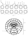
- a light distribution curve (LVK) 7 of the pendant lamp 1 is shown. It can be seen that the LVK 7 has a portion in the primary radiation direction 61 and one in the secondary radiation direction 62.
- the section of the LVK 7 in the secondary radiation direction 62 is formed in particular by the rear light 521 of the pendant lamp 1. It is defined by the contour of the reflection exit regions 422 of the inner sides 42 of the lenses 4.
- the section of the LVK 7 in the primary radiation direction 61 is formed in particular by the direct light component 51 and by the diffuse light 522 of the pendant lamp 1. It is defined by the nature of the central regions 412 and the edge regions 414 outer sides 41 of the lenses 4.
- the present disclosure also includes embodiments having any combination of features that are mentioned or shown above or below various embodiments. It also comprises individual features in the figures, even if they are shown there in connection with other features and / or are not mentioned above or below. Also, the alternatives of embodiments described in the figures and the description and individual alternatives of their features may be excluded from the subject matter of the invention or from the disclosed subject matter.
- the disclosure includes embodiments that include only the features described in the claims and in the embodiments, as well as those that include additional other features. Furthermore, the term “comprising” and derivatives thereof do not exclude other elements or steps. Also closes the indefinite article "a” or “one” and derivatives thereof are not sufficient. The functions of several features listed in the claims may be fulfilled by a unit or a step.
Description
- Die Erfindung betrifft eine Leuchte mit einer Primärabstrahlungsrichtung zur Beleuchtung eines Vorderraums der Leuchte und einer der Primärabstrahlung entgegengesetzte Sekundärabstrahlungsrichtung zur Beleuchtung eines Rückraums der Leuchte gemäss dem Oberbegriff des unabhängigen Anspruchs 1.
- Solche Leuchten umfassen typischerweise eine Platine mit einer Montageoberfläche, auf der ein LED-Leuchtmittel montiert ist und eine Optik. Die Optik deckt das LED-Leuchtmittel in dessen Abstrahlrichtung ab. Sie weist eine der Platine zugewandte Innenseite und einer der Platine abgewandten Aussenseite auf. Solche Leuchten können zur Beleuchtung von Räumen als Stehleuchten, Wandleuchten, Deckenleuchten oder Pendelleuchten eingesetzt werden.
- Zur Beleuchtung von Räumen werden heutzutage verschiedenartige Leuchten eingesetzt, die beispielsweise stehend, direkt auf Wänden, an Decken, abgependelt oder angebaut beziehungsweise befestigt sein können. Insbesondere bei Stehleuchten und bei Pendelleuchten ist es dabei häufig gewünscht, dass Licht von der Leuchte sowohl in einen Vorderraum der Leuchte als auch in einen Rückraum der Leuchte abgestrahlt wird.
- Beispielsweise sind Pendelleuchten häufig dazu ausgestaltet, Licht sowohl in eine Primärabstrahlungsrichtung abzugeben, in welcher der Vorderraum der Leuchte beleuchtet werden soll, als auch in eine Sekundärabstrahlungsrichtung, in der der Rückraum der Leuchte beleuchtet werden soll. Die Primärabstrahlungsrichtung und die Sekundärabstrahlungsrichtung sind typischerweise entgegengesetzt, wobei bei Pendelleuchten erstere beispielsweise nach unten zum Boden hin und zweitere nach oben zur Decke hin verlaufen kann.
- Weiter werden bei modernen Leuchten zunehmend LED-Leuchtmittel mit einer oder mehreren auf einer Platine montierten Leuchtdioden eingesetzt. LED-Leuchtmittel können aus verschiedenen Gründen vorteilhaft sein. Beispielsweise sind sie verhältnismässig langlebig, sparsam und flexibel gestaltbar. Zudem können LED-Leuchtmittel verhältnismässig präzise konfiguriert werden. Zum Beispiel können sie verhältnismässig genau definierte Lichtverteilungskurven (LVK) aufweisen, die je nach Anwendung angepasst werden können. Dabei umfassen solche Leuchten zum Festlegen der LVK beziehungsweise zum Erzeugen einer bevorzugten Ausleuchtung oder einer bestimmten Atmosphäre häufig Optiken, die jeweils einer Leuchtdiode oder auch mehreren Leuchtdioden zusammen zugeordnet sind. Zudem können die Leuchten zum gleichen Zweck auch elektronische Steuerungen, Reflektoren, Refraktoren oder ähnliche Mittel umfassen.
- Da Leuchtdioden von LED-Leuchtmitteln typischerweise Licht nur in einen Halbraum beziehungsweise in einer Richtung abstrahlen, werden heutzutage zusätzliche Massnahmen getroffen, um eine Leuchte der vorstehenden Art mit entgegengesetzter Primär- und Sekundärabstrahlungsrichtung realisieren zu können. Beispielsweise ist es bekannt, in einer Leuchte zwei Platinen mit Leuchtdioden um 180° zueinander zu verdrehen, sodass sich die zugehörigen Leuchtdioden in entgegengesetzter Richtungen erstrecken. Oder es werden Leuchtdioden an beiden Seiten beziehungsweise auf beiden Oberflächen einer zugehörigen Platine montiert. Dabei werden zur sauberen Definition der LVK typischerweise auf beiden Seiten der einen oder zwei Platinen Optiken angeordnet, wobei eine die Abstrahlcharakteristika der Leuchte in den Vorderraum und eine diejenigen in den Rückraum beeinflusst.
- Die vorstehend beschriebene Art von Leuchten mit jeweils entgegengesetzten Leuchtdioden, die jeweils von zugehörigen Optiken abgedeckt sein müssen, kann verschiedene Nachteile nach sich ziehen. Beispielsweise können die Leuchten konstruktiv verhältnismässig breit oder hoch sein, was aus ästhetischen und anderen Gründen meist unerwünscht ist. Zudem werden in solchen Leuchten meist verhältnismässig viele Leuchtdioden und Optiken verbaut, was den Material- und Montageaufwand der Leuchte erhöhen kann. Weiter ist in der
US 2011/0235318 A1 ein röhrenförmiges LED-Leuchtmittel als Ersatz für eine Leuchtstoffröhre beschrieben. - Vor diesem Hintergrund ist es Aufgabe der nachfolgenden Erfindung, eine Leuchte vorzuschlagen, die eine effiziente und vordefinierte Ausleuchtung eines Vorder- und Rückraums in einer kompakten Bauweise ermöglicht.
- Die Aufgabe wird erfindungsgemäss durch eine Leuchte gelöst, wie sie durch die Merkmale des unabhängigen Anspruchs 1 definiert ist. Vorteilhafte Ausführungsvarianten der Erfindung ergeben sich aus den abhängigen Ansprüchen.
- Insbesondere umfasst eine Leuchte mit einer Primärabstrahlungsrichtung zur Beleuchtung eines Vorderraums der Leuchte und einer der Primärabstrahlungsrichtung im Wesentlichen entgegengesetzte Sekundärabstrahlungsrichtung zur Beleuchtung eines Rückraums der Leuchte eine Platine, ein LED-Leuchtmittel und eine Optik. Die Platine weist eine Montageoberfläche auf, auf der das LED-Leuchtmittel montiert ist. Die Optik deckt das LED-Leuchtmittel beispielsweise in dessen Abstrahlbereich beziehungsweise in dessen Abstrahlrichtung ab. Sie umfasst eine der Platine zugewandte Innenseite und eine der Platine abgewandte Aussenseite. Weiter weist die Optik eine Direktlichtstruktur und eine Indirektlichtstruktur auf. Die Direktlichtstruktur leitet einen Direktlichtanteil von vom LED-Leuchtmittel abgestrahltem Licht an die Aussenseite der Optik. Die Indirektlichtstruktur leitet einen Indirektlichtanteil des vom LED-Leuchtmittel abgestrahlten Lichts an die Innenseite der Optik. Die Platine weist in einem Bereich, an dem der Indirektlichtanteil des vom LED-Leuchtmittel abgestrahlten Lichts auf eine Ebene der Montageoberfläche der Platine auftritt, eine durchgehende Öffnung auf.
- Das LED-Leuchtmittel kann eine oder mehrere Leuchtdioden umfassen. Dabei ist insbesondere die Leuchtdiode des LED-Leuchtmittels an der Montageoberfläche der Platine befestigt. Andere Komponenten des LED-Leuchtmittels wie beispielsweise ein Betriebsgerät können auch an der Platine montiert sein.
- Die Optik kann eine Linse sein. Sie kann insbesondere aus einem transparenten Kunststoff hergestellt sein. Dies ermöglicht, dass die Linse präzise und effizient beispielsweise in einem Spritzgussprozess hergestellt werden kann.
- Das die Öffnung der Platine durchdringende von der Optik reflektierte Licht kann in Primärrichtung abgestrahlt und so zur Beleuchtung des Vorderraums der Leuchte eingesetzt werden oder in Sekundärrichtung abgestrahlt und so zur Beleuchtung des Rückraums der Leuchte.
- Der Begriff "Platine" im Zusammenhang mit der erfindungsgemässen Leuchte kann sich insbesondere auf eine Leiterplatte beziehungsweise eine gedruckte Schaltung (PCB) beziehen, die ein Träger für elektronische Bauteile und insbesondere für die Komponenten des LED-Leuchtmittels wie beispielsweise Leuchtdiode oder Betriebsgerät ist. Sie dient insbesondere der mechanischen Befestigung und elektrischen Verbindung der elektronischen Bauteile. Leiterplatten bestehen üblicherweise aus elektrisch isolierendem Material mit daran haftenden, leitenden Verbindungen beziehungsweise Leiterbahnen. Als isolierendes Material ist faserverstärkter Kunststoff üblich. Es kann aber insbesondere auch Aluminium sein, was aus ästhetischen Gründen oder zur verbesserten Lichtreflexion bevorzugt sein kann.
- Der Begriff "Ebene der Montageoberfläche" im Zusammenhang mit der Erfindung bezieht sich auf die Ebene, in der die Montageoberfläche liegt. Dabei tritt der Indirektlichtanteil auf diese Ebene auf, indem er die Ebene kreuzt oder von der Platine reflektiert beziehungsweise absorbiert wird.
- Der Begriff "Abdecken" im Zusammenhang mit der Optik und dem LED-Leuchtmittel kann sich insbesondere darauf beziehen, dass das vom LED-Leuchtmittel abgestrahlte Licht die Optik durchdringt. Dazu kann es genügen, wenn die Optik die leuchtenden Komponenten des LED-Leuchtmittels also vor allem die eine oder mehrere Leuchtdiode(n) so umgibt, dass das abgestrahlte Licht die Optik durchdringt beziehungsweise in die Optik geleitet wird.
- Indem die Optik mit ihrer Direktlichtstruktur und ihrer Indirektlichtstruktur das vom LED-Leuchtmittel abgestrahlte Licht in einen Direktlichtanteil und einen Indirektlichtanteil auftrennt und diese beiden Anteile getrennt auf ihre Aussen- und Innenseiten leitet, kann erfindungsgemäss das Licht eines LED-Leuchtmittels sowohl zur Beleuchtung des Vorderraums als auch des Rückraums verwendet werden. Die Aufteilung des Direkt- zu Indirektlichtanteils kann beispielsweise etwa 70% zu etwa 30% betragen. Die Öffnung in der Platine ermöglicht dabei, dass der Indirektlichtanteil zumindest teilweise auf die gegenüberliegende Seite der Platine gelangen kann. Damit kann erreicht werden, dass Licht auch auf einer Seite der Platine abgestrahlt werden kann, die nicht mit einer Leuchtdiode bestückt ist.
- Auf diese Weise kann in der Leuchte eine oder mehrere Platinen eingesetzt werden, die nur auf einer Seite mit Leuchtdioden bestückt sind und auch nur auf dieser bestückten Seite von einer oder mehreren Optiken abgedeckt sind. Dadurch kann die Leuchte verhältnismässig kompakt und platzsparend ausgestaltet sein. Zudem kann sie verhältnismässig energieeffizient betrieben werden und verhältnismässig wenig Bauteile umfassen.
- Indem in der Leuchte eine lediglich einseitig bestückte Platine verwendet werden kann, kann die Leuchte auch komponentenreduziert sein, was eine Konstruktion und Herstellung mit verhältnismässig wenig Aufwand ermöglicht. Weiter kann die Leuchte auch so ausgestaltet sein, dass die Rückseite der Platine gleichzeitig die Rückseite eines Gehäuses der Leuchte bildet. Dadurch kann die komponenten- und aufwandreduzierte Konstruktion und Herstellung der Leuchte weiter unterstützt werden.
- Vorzugsweise umfasst die Indirektlichtstruktur der Optik einen Reflexionsbereich der Aussenseite der Optik, der so geformt ist, dass bezüglich des vom LED-Leuchtmittel abgestrahlten Lichts Totalreflexion auftritt. Dazu kann der Reflexionsbereich der Aussenseite poliert ausgeführt sein. Ein solcher Reflexionsbereich an der Aussenseite der Optik ermöglicht ein effizientes Umleiten des vom LED-Leuchtmittel abgestrahlten Lichts in eine quasi entgegengesetzte Richtung.
- Unter dem Begriff "Totalreflexion" wird in diesem Zusammenhang ein bekanntes Phänomen verstanden, das bei sichtbarem Licht an der Grenzfläche zweier nicht absorbierender Medien mit verschieden grosser Ausbreitungsgeschwindigkeit auftritt. Dabei tritt das Licht nicht mehr überwiegend vom ersten in das zweite Medium ein, sondern wird nahezu vollständig reflektiert beziehungsweise ins erste Medium zurückgeworfen, wenn der Einfallswinkel einen bestimmten Wert, den sogenannten Grenzwinkel der Totalreflexion, überschreitet. Es ist zu beachten, dass eine totale beziehungsweise vollständige Reflexion einer Welle wie einer Lichtwelle grundsätzlich eine Idealisierung darstellt, da auch der vollständig reflektierten Strahlung in der Praxis immer ein Teil durch Absorption verloren geht.
- Vorzugsweise umfasst die Direktlichtstruktur der Optik einen Zentralbereich der Aussenseite der Optik, der zentral benachbart zum LED-Leuchtmittel angeordnet ist. Ein solcher Zentralbereich ermöglicht, dass die Leuchte einen Direktlichtbereich aufweist, über den das Licht des LED-Leuchtmittels effizient abgestrahlt werden kann. Wie weiter unten detaillierter beschrieben, kann das über den Zentralbereich abgestrahlte Direktlicht über eine Einkoppelfläche und eine Auskoppelfläche der Optik gesteuert werden.
- Dabei ist der Zentralbereich der Optik vorzugsweise getrübt. Die Trübung des Zentralbereichs kann beispielsweise über eine Erodierung oder Glasperlenbestrahlung der Oberfläche der Aussenseite des Zentralbereichs erzeugt werden. Alternativ dazu kann die Oberfläche der Aussenseite mit Mikrobeziehungsweise Nanostrukturen versehen sein, die das Licht streuen. Die vorstehend beschaffenen Zentralbereiche, also erodierte, glasperlenbestrahlte und/oder mit Mikrobeziehungsweise Nanostrukturen versehene, werden hier allesamt als getrübt bezeichnet. Eine solche Ausgestaltung des Zentralbereichs ermöglicht eine Definition einer erwünschten Lichtverteilungskurve (LVK) der Leuchte. Insbesondere kann ein Blendeffekt oder Spotlight-Effekt der Leuchte vermindert werden.
- Die Direktlichtstruktur der Optik umfasst vorzugsweise einen Reflexionsbereich der Innenseite der Optik, der in einem flachen Winkel vom LED-Leuchtmittel abgestrahltes Licht in den Zentralbereich der Aussenseite der Optik leitet. Der Begriff "flacher Winkel" im Zusammenhang mit dem LED-Leuchtmittel kann sich auf einen Raumwinkel beziehen, der im Vergleich zu einer Hauptabstrahlungsrichtung des LED-Leuchtmittels flach ist. Insbesondere kann er sich auf einen spitzen Winkel zwischen der Abstrahlrichtung des LED-Leuchtmittels und der Montageoberfläche der Platine beziehen. Ein solcher spitzer Winkel kann beispielsweise kleiner als 30°, kleiner als 20°, kleiner als 15° oder kleiner als 10° sein. In anderen Worten ist der flache Winkel des vom LED-Leuchtmittel abgestrahlten Lichts ein Winkel, der gemessen zur Hauptabstrahlungsrichtung gross ist, jedoch typischerweise 90° gemessen zur Hauptabstrahlungsrichtung nicht übersteigt. Er kann also gemessen zur Hauptabstrahlungsrichtung beispielsweise grösser 60° und kleiner als 90° oder grösser 70° und kleiner als 90° oder grösser 75° und kleiner als 90° oder grösser 80° und kleiner als 90° sein.
- Heutige Leuchtdioden und insbesondere phosphorvergusskonvertierte Leuchtdioden weisen eine Farbverschiebung über ihren Abstrahlungswinkelbereich auf. Dabei ist das in einem verhältnismässig flachen oder kleinen Winkel abgestrahlte Licht typischerweise eher gelb und das in einem grossen Winkel also gegen die Hauptabstrahlungsrichtung abgestrahlte Licht eher blau. Mit der Umleitung des in einem flachen Winkel abgestrahlten Lichts in den Zentralbereich kann einerseits verhindert werden, dass das eher gelbliche Licht das Lichtbild der Leuchte stört und andererseits kann es mit dem eher blauen Licht gemischt werden, wodurch eine homogenere Lichtfarbe im Lichtbild der Leuchte erzeugt werden kann.
- Der Reflexionsbereich der Aussenseite der Optik umgibt vorzugsweise den Zentralbereich der Aussenseite der Optik. So kann eine gleichmässige Abstrahlung und eine bevorzugte LVK erreicht werden. Dabei umfasst die Direktlichtstruktur der Optik vorzugsweise einen Peripherbereich der Aussenseite der Optik, der den Reflexionsbereich der Aussenseite der Optik umgibt. Durch den Peripherbereich der Aussenseite der Optik kann insbesondere Licht austreten, das in einem Winkel vom LED-Leuchtmittel abgestrahlt wird, der grösser als der zu einer Umlenkung am Reflexionsbereich der Innenseite der Optik führende Winkel und kleiner als der zu einer Umlenkung am Reflexionsbereich der Aussenseite der Optik führende Winkel ist.
- Bevorzugt weist die Optik eine Diffuslichtstruktur auf, die einen Randbereich der Aussenseite der Optik umfasst, wobei die Diffuslichtstruktur der Optik einen von der Platine reflektierten Teil des Indirektlichtanteils des vom LED-Leuchtmittel abgestrahlten Lichts an den Randbereich der Aussenseite der Optik leitet. Mit einer solchen Diffuslichtstruktur kann das Direktlicht des LED-Leuchtmittels über die Leuchte nivelliert werden. Dies ermöglicht, dass die Leuchte weniger Lichtkontraste aufweist, was für einen Betrachter als angenehm empfunden werden kann. Die LVK der Leuchte kann so bevorzugt angepasst werden.
- Bei der Ausgestaltung der Leuchte mit der Diffuslichtstruktur kann insbesondere die Platine aus Aluminium oder einem anderen geeigneten gut reflektierenden Material hergestellt, beschichtet oder abgedeckt sein. So kann das Diffuslicht der Leuchte verbessert eingestellt werden.
- Vorzugsweise umfasst die Indirektlichtstruktur der Optik einen Reflexionsaustrittsbereich an der Innenseite der Optik, der an die durchgehende Öffnung der Platine angrenzt. Ein solcher Reflexionsaustrittsbereich ermöglicht es, reflektiertes Licht von der Innenseite der Optik abzustrahlen. Dabei weist der Reflexionsaustrittsbereich vorzugsweise eine Kontur auf, mit der eine Lichtverteilungskurve des via dem Reflexionsaustrittsbereich durch die durchgehende Öffnung der Platine austretenden Indirektlichtanteils des vom LED-Leuchtmittel abgestrahlten Lichts eingestellt wird. Die Kontur kann insbesondere an der Innenseite der Optik ausgebildete Wellen und/oder Prismen, Facetten, Mikrostrukturen, Nanostrukturen oder dergleichen umfassen. Ein solcher Reflexionsaustrittsbereich ermöglicht eine effiziente Einstellung des die Öffnung der Platine durchdringenden Lichts.
- Der Reflexionsaustrittsbereich kann in der Ebene der Montageoberfläche der Platine liegen. Vorzugsweise erstreckt er sich jedoch in die durchgehende Öffnung der Platine hinein. Dabei kann er auch die Öffnung der Platine durchragen. Eine solche Ausgestaltung ermöglicht eine freiere Gestaltung der Kontur des Reflexionsaustrittsbereichs, wodurch die zugehörigen Abstrahlcharakteristika verbessert eingestellt werden können. Zudem ermöglicht eine solche Ausgestaltung, dass die Optik bezüglich des LED-Leuchtmittels zentriert beziehungsweise exakt positioniert und ausgerichtet wird.
- Die Optik und die Platine können auch mit weiteren Mitteln ausgestattet sein, die eine zusätzliche Zentrierung beziehungsweise Ausrichtung und Positionierung ermöglichen. Beispielsweise kann die Optik Dome oder Zylinder an seiner Innenseite und die Platine korrespondierende Bohrungen aufweisen. Die Optik wird dann beim Zusammenbau zusätzlich zentriert beziehungsweise positioniert und ausgerichtet, indem die Dome in die Bohrungen eingreifen.
- Bei der Positionierung und Ausrichtung der Optik zum LED-Leuchtmittel kann die Optik so angeordnet sein, dass das LED-Leuchtmittel in einer Symmetriereferenz und insbesondere in einer Symmetrieachse der Optik liegt. Eine solche Anordnung kann als "zentriert" bezeichnet werden. Sie ermöglicht eine gleichmässige vordefinierbare Abstrahlung von Licht. Alternativ dazu kann das LED-Leuchtmittel auch ausserhalb der Symmetriereferenz der Optik liegen, was eine asymmetrische vordefinierbare Abstrahlung von Licht aus der Leuchte ermöglicht. Je nach Anwendung der Leuchte kann ihre LVK also über die Positionierung und Ausrichtung der Optik zum LED-Leuchtmittel eingestellt werden.
- Die durchgehende Öffnung der Platine ist ringsegmentförmig ausgestaltet, wobei das LED-Leuchtmittel mittig im Ringsegment der durchgehenden Öffnung montiert ist. Ringsegmentförmig kann in einer Aufsicht C-förmig sein. Eine solche Ausgestaltung der Öffnung in der Platine ermöglicht zum einen eine effiziente und ästhetisch ansprechende Durchführung von Licht auf die Rückseite der Platine. Zum anderen wird eine Wärmeabfuhr über den Steg des Ringsegments ermöglicht, was für den Betrieb des LED-Leuchtmittels wichtig sein kann.
- Vorzugsweise sind bei der Leuchte eine Mehrzahl von LED-Leuchtmitteln auf der Montageoberfläche der Platine montiert, die von einer Mehrzahl von identischen Optiken abgedeckt sind, wobei jeweils eine der Optiken eines der LED-Leuchtmittel abdeckt. Eine solche Ausgestaltung der Leuchte ermöglicht es eine grössere Fläche sowohl im Vorderraum als auch im Rückraum zu beleuchten.
- Die Mehrzahl von Optiken kann identische Optiken umfassen, welche die LED-Leuchtmittel in identischer Weise abdecken. Sie kann auch identische Optiken umfassen, welche die LED-Leuchtmittel in verdrehter oder versetzter Weise abdecken. Weiter kann sie unterschiedliche Optiken umfassen. Auch eine Kombination der vorstehenden Varianten von Optiken kann von der Mehrzahl von Optiken umfasst sein. Auf diese Weise kann die LVK der Leuchte äusserst flexibel auf den Einsatzzweck der Leuchte hin angepasst werden.
- Dabei ist die Mehrzahl von Optiken vorzugsweise einstückig ausgebildet. Eine solche einstückige Ausgestaltung ermöglicht eine verhältnismässig einfache und effiziente Montage beziehungsweise Fertigung der Leuchte.
- Weiter weist dabei die Platine bevorzugt eine Mehrzahl von ringsegmentförmigen durchgehenden Öffnungen auf, wobei jeweils eines der Mehrzahl von LED-Leuchtmittel im Ringsegment einer der Mehrzahl von durchgehenden Öffnungen montiert ist und wobei die Ringsegmente benachbarter durchgehender Öffnungen zueinander verdreht sind. Eine solche Anordnung der ringsegmentförmigen Öffnungen ermöglicht eine gleichmässige Lichtverteilung und ein ästhetisch ansprechendes Erscheinungsbild der Leuchte.
- Weitere vorteilhafte Ausgestaltungen der Erfindung ergeben sich aus der nachfolgenden Beschreibung von Ausführungsbeispielen mithilfe der schematischen Zeichnungen.
- Insbesondere wird im Folgenden die erfindungsgemässe Leuchte unter Bezugnahme auf die beigefügten Zeichnungen anhand von Ausführungsbeispielen detaillierter beschrieben. Es zeigen:
- Fig. 1
- eine Querschnittsansicht eines Teils eines Ausführungsbeispiels einer erfindungsgemässen Leuchte;
- Fig. 2
- eine Ansicht an einen Teil einer Linsenanordnung mit mehreren Linsen der Leuchte von
Fig. 1 ; - Fig. 3
- eine Ansicht an einen Teil eines Trägers der Leuchte von
Fig. 1 ; und - Fig. 4
- eine Lichtverteilungskurve der Leuchte von
Fig. 1 . - Bestimmte Ausdrücke werden in der folgenden Beschreibung aus praktischen Gründen verwendet und sind nicht einschränkend zu verstehen. Die Wörter "rechts", "links", "unten" und "oben" bezeichnen Richtungen in der Zeichnung, auf die Bezug genommen wird. Die Ausdrücke "nach innen", "nach aussen" "unterhalb", "oberhalb", "links", "rechts" oder ähnliche werden zur Beschreibung der Anordnung bezeichneter Teile zueinander, der Bewegung bezeichneter Teile zueinander und der Richtungen hin zum oder weg vom geometrischen Mittelpunkt der Erfindung sowie benannter Teile derselben verwendet wie sie in den Fig. dargestellt sind. Diese räumlichen Relativangaben umfassen auch andere Positionen und Ausrichtungen als die in den Fig. dargestellten. Zum Beispiel wenn ein in den Fig. dargestelltes Teil umgedreht wird, sind Elemente oder Merkmale, die als "unterhalb" beschrieben sind, dann "oberhalb". Die Terminologie umfasst die oben ausdrücklich erwähnten Wörter, Ableitungen von denselben und Wörter ähnlicher Bedeutung.
-
Fig. 1 zeigt ausgewählte Bauteile einer Pendelleuchte 1 als Ausführungsbeispiel einer erfindungsgemässen Leuchte. Neben den in derFig. 1 gezeigten Bauteilen enthält die Pendelleuchte 1 weitere Bauteile wie beispielsweise ein Gehäuse oder eine Aufhängeeinrichtung. Diese weiteren Bauteile sind jedoch für die vorliegende Erfindung von untergeordneter Bedeutung und deshalb in den Fig. nicht dargestellt. - Die Pendelleuchte 1 umfasst eine Platine 3, eine Vielzahl von LED-Leuchtmitteln 2 und eine einteilige Linsenanordnung aus einem transparenten Kunststoff mit einer Vielzahl von Linsen 4 als Optiken. Zur besseren Übersichtlichkeit ist in der
Fig. 1 ein Einzelnes der LED-Leuchtmittel 2 und eine Einzelne der Linsen 4 der Linsenanordnung dargestellt. Entsprechend ist im nachfolgenden zugehörigen Text dieses Einzelne der LED-Leuchtmittel 2 und diese Einzelne der Linsen 4 beschrieben. Die weiteren der LED-Leuchtmittel 2 und der Linsen 4 sind analog ausgestaltet. - Das LED-Leuchtmittel 2 weist eine Leuchtdiode 21 auf, die auf einer Montageoberfläche 31 der Platine 3 montiert ist. Die Montageoberfläche 31 ist dabei an einer Unterseite der Platine 3 ausgebildet. Die Platine 3 weist weiter eine durchgehende Öffnung 32 auf. Die Leuchtdiode 21 des LED-Leuchtmittels 2 ist mittig in der Öffnung 32 der Platine 3 angeordnet. Die Form und Ausgestaltung der Öffnung 32 ist weiter unten im Zusammenhang mit der
Fig. 3 detaillierter beschrieben. Die Platine 3 ist zum Beispiel aus Aluminium hergestellt. - Die Linse 4 weist eine der Platine 3 abgewandte Aussenseite 41 und eine der Platine 3 zugewandte Innenseite 42 auf. Die Aussenseite 41 der Linse 4 umfasst einen gerade unterhalb der Leuchtdiode 21 angeordneten Zentralbereich 412, einen den Zentralbereich 412 umgebenden Reflexionsbereich 411, einen den Reflexionsbereich 411 umgebenden Peripherbereich 413 und einen den Peripherbereich 413 umgebenden Randbereich 414. Die Innenseite 42 der Linse 4 umfasst einen die Leuchtdiode 21 umgebenden Reflexionsbereich 421 und einen in die Öffnung 32 der Platine 3 hineinragenden Reflexionsaustrittsbereich 422. Der Reflexionsaustrittsbereich 422 ist mit einer Prismen umfassenden Kontur ausgebildet.
- Die Leuchtdiode 21 des LED-Leuchtmittels 2 ist von der Platine 3 aus nach unten gerichtet. Das heisst, sie strahlt Licht 5 mit einer vertikal nach unten verlaufenden Hauptabstrahlungsrichtung ab. Insbesondere wird das Licht 5 vom LED-Leuchtmittel 2 über einen bestimmten Winkelbereich abgestrahlt. Dabei hat das in einem flachen Winkel abgestrahlte Licht 5 ein eher gelbliches Spektrum und das in einem spitzen Winkel zur Hauptabstrahlungsrichtung also quasi in der Hauptabstrahlungsrichtung abgestrahlte Licht 5 ein eher bläuliches Spektrum.
- Ein Direktlichtanteil 51 des vom LED-Leuchtmittel 2 abgestrahlten Lichts 5 wird von einer Direktlichtstruktur der Linse 4 auf den Zentralbereich 412 der Aussenseite 41 geleitet und von dort aus von der Pendelleuchte 1 abgestrahlt. Der Direktlichtanteil 51 umfasst dabei einerseits vom LED-Leuchtmittel 2 abgestrahltes Licht 5, das gerade beziehungsweise direkt von der Leuchtdiode 21 in Richtung des Zentralbereichs 412 abgestrahlt wird. Dieses vom LED-Leuchtmittel 2 abgestrahlte Licht 5 weist einen verhältnismässig spitzen Abstrahlungswinkel zur Hauptabstrahlungsrichtung auf und ist somit eher bläulich. Andererseits umfasst der Direktlichtanteil 51 Licht 5 das von der Leuchtdiode 21 auf den Reflexionsbereich 421 an der Innenseite 42 der Linse 4 auftrifft und von diesem in den Zentralbereich 412 der Aussenseite 41 der Linse 4 umgeleitet wird. Dieses vom LED-Leuchtmittel 2 abgestrahlte Licht 5 weist einen verhältnismässig flachen Abstrahlungswinkel auf und ist somit eher gelblich.
- Der Direktlichtanteil 51 des vom LED-Leuchtmittel 2 abgestrahlten Lichts 5 weist also ursprünglich eher gelbliche und eher bläuliche Anteile auf, die gemischt werden. Damit werden die Farbverschiebungen des vom LED-Leuchtmittel 2 abgestrahlten Lichts 5 im Direktlichtanteil 51 ausgeglichen. Der Reflexionsbereich 421 der Innenseite 42 und der Zentralbereich 412 der Aussenseite 41 sind von der Direktlichtstruktur der Linse 4 umfasst.
- Ein Indirektlichtanteil 52 des vom LED-Leuchtmittel 2 abgestrahlten Lichts 5 wird vom Reflexionsbereich 411 der Aussenseite 41 der Linse 4 reflektiert beziehungsweise umgeleitet. Der Indirektlichtanteil 52 umfasst dabei im Wesentlichen alles vom LED-Leuchtmittel 2 abgestrahlte Licht 5, das nicht im Direktlichtanteil 51 enthalten ist. Der Direktlichtanteil 51 umfasst etwa 70% des vom LED-Leuchtmittel 2 abgestrahlten Lichts 5 und der Indirektlichtanteil 52 etwa 30%.
- Der vom Reflexionsbereich 411 der Aussenseite 41 der Linse 4 umgeleitete Indirektlichtanteil 52 trifft einerseits auf den Reflexionsaustrittsbereich 422 der Innenseite 42 der Linse 4 und wird von dort als Rücklicht 521 von der Pendelleuchte 1 abgestrahlt. Über die die Prismen umfassende Kontur des Reflexionsaustrittsbereichs 422 wird die Charakteristik des Rücklichts 521 festgelegt. Der Reflexionsbereich 411 der Aussenseite 41 und der Reflexionsaustrittsbereich 422 der Innenseite 42 sind von einer Indirektlichtstruktur der Linse 4 umfasst.
- Andererseits trifft der vom Reflexionsbereich 411 der Aussenseite 41 umgeleitete Indirektlichtanteil 52 auf die Montageoberfläche 31 der Platine 3, wird von dieser wiederum reflektiert und über den Randbereich 414 der Aussenseite 41 der Linse 4 als Diffuslicht 522 von der Pendelleuchte 1 abgestrahlt. Mit dem Diffuslicht 522 wird die Leuchtfläche der Leuchte 1 als Ganzes zum Leuchten gebracht, was zu einer Nivellierung des Direktlichtanteils 51 führt. Dadurch ergeben sich für das menschliche Auge geringere Lichtkontraste beim Anschauen der Leuchtfläche der Pendelleuchte 1, was typischerweise als angenehm und weniger ermüdend empfunden wird. Der Reflexionsbereich 411 der Aussenseite 41, der Peripherbereich 413 der Aussenseite 41 und der Randbereich 414 der Aussenseite 41 sind von einer Diffuslichtstruktur der Linse 4 umfasst.
- Die Pendelleuchte 1 weist eine vertikal abwärts verlaufende Primärabstrahlungsrichtung 61 auf, in die der Direktlichtanteil 51 des vom LED-Leuchtmittel 2 abgestrahlten Lichts 5 und das Diffuslicht 522 abgestrahlt wird. In die Primärabstrahlungsrichtung 61 beleuchtet die Pendelleuchte 1 einen Vorderraum der Pendelleuchte 1. Zusätzlich weist die Leuchte 1 eine Sekundärabstrahlungsrichtung 62 auf, in die insbesondere das Rücklicht 521 abgestrahlt wird. In die Sekundärabstrahlungsrichtung 62 beleuchtet die Pendelleuchte 1 einen Rückraum der Pendelleuchte 1.
- Die Ausgestaltung der Pendelleuchte 1 mit einer Platine 3 mit durchgehenden Öffnungen 32 und der Linsenanordnung mit den Linsen 4 ermöglicht, dass die Platine 3 nur einseitig mit Leuchtdioden 21 bestückt ist und trotzdem der Rückraum der Pendelleuchte 1 beleuchtet werden kann. Dies erlaubt eine verhältnismässig geringe Aufbauhöhe der Pendelleuchte 1 und einen verhältnismässig geringen Bedarf an Bauteilen.
- Um Wiederholungen in den Fig. und der zugehörigen Beschreibung der verschiedenen Aspekte und Ausführungsbeispielen zu vermeiden, sollen bestimmte Merkmale als gemeinsam für verschieden Aspekte und Ausführungsbeispiele verstanden werden. Das Weglassen eines Aspekts in der Beschreibung oder einer Fig. lässt nicht darauf schliessen, dass dieser Aspekt in dem zugehörigen Ausführungsbeispiel fehlt. Vielmehr kann ein solches Weglassen der Klarheit und dem Verhindern von Wiederholungen dienen. In diesem Zusammenhang gilt für die gesamte weitere Beschreibung folgende Festlegung: Sind in einer Figur zum Zweck zeichnerischer Eindeutigkeit Bezugszeichen enthalten, aber im unmittelbar zugehörigen Beschreibungstext nicht erwähnt, so wird auf deren Erläuterung in vorangehenden Figurenbeschreibungen Bezug genommen. Sind ausserdem im unmittelbar zu einer Figur gehörigen Beschreibungstext Bezugszeichen erwähnt, die in der zugehörigen Figur nicht enthalten sind, so wird auf die vorangehenden und nachstehenden Figuren verwiesen. Ähnliche Bezugszeichen in zwei oder mehreren Fig. stehen für ähnliche oder gleiche Elemente.
- In der
Fig. 2 sind die Bauteile der Pendelleuchte 1 derFig. 1 von unten her gezeigt. Darin ist ersichtlich, dass die Linsenanordnung einstückig mit mehreren Reihen von identischen Linsen 4 ausgebildet ist. Von unten her sind die Aussenseiten 41 der Linsen 4 sichtbar. Jede Linse 4 der Linsenanordnung ist einem LED-Leuchtmittel 2 (inFig. 2 nicht ersichtlich) zugeordnet. - Die Zentralbereiche 412 der Aussenseiten 41 der Linsen 4 sind jeweils kreisförmig ausgestaltet. Die Reflexionsbereiche 411 sind jeweils ringförmig um einen der Zentralbereiche 412 herum und die Peripherbereiche 413 jeweils ringförmig um einen der Reflexionsbereiche 411 herum geformt. Um die Peripherbereiche 413 herum sind die Randbereiche 414 der Aussenseiten 41 der Linsen 4 angeordnet, wobei diese aneinander angrenzen und miteinander verbunden sind.
- Die Zentralbereiche 412 und die Randbereiche 414 der Aussenseiten 41 der Linsen 4 sind mittels Erodieren, mittels Glasperlenstrahlen oder mittels einer sonstigen Mikrostrukturierungstechnik mattiert. Dadurch kann einerseits eine störende Direktsicht auf die phosphorgelben Leuchtdioden 21 vermieden und andererseits eine sanft verlaufende Ästhetik bei der leuchtenden Pendelleuchte 1 ermöglicht werden. Die Bereiche der Aussenseiten 41 und der Innenseiten 42 der Linsen 4, die reflektierende Eigenschaften aufweisen, sind poliert, um eine möglichst ideale Reflexion zu ermöglichen.
- Die Vereinigung der Mehrzahl von Linsen 4 in der Linsenanordnung ermöglicht eine effiziente Realisierung beispielsweise im Spritzguss. Zudem erlaubt dies auch eine effiziente Montage, wobei die Linsenanordnung beispielsweise über vier bis acht Schrauben oder über ein Einschieben in ein umlaufendes Profil befestigt werden kann.
-
Fig. 3 zeigt die Bauteile der Pendelleuchte 1 derFig. 1 von oben her. Darin ist ersichtlich, dass die durchgehenden Öffnungen 32 der Platine 3 analog zu den Linsen 4 der Linsenanordnung in mehreren Reihen angeordnet sind. Die Öffnungen 32 sind ringsegmentförmig oder C-förmig ausgestaltet. Innerhalb der Ringsegmente der Öffnungen 32 ist jeweils ein kreisförmiger Inselabschnitt 33 beziehungsweise Halbinselabschnitt der Platine 3 angeordnet, an dessen Unterseite die Leuchtdiode 21 einer der LED-Leuchtmittel 2 montiert ist. - Die Inselabschnitte 33 sind jeweils über einen Steg 34 mit einem Grundabschnitt 35 der Platine 3 verbunden. Die Stege 34 dienen einerseits dazu, die Inselabschnitte 33 zu tragen und andererseits Wärme von den Leuchtdioden 21 abzuführen. Benachbarte Öffnungen 32 sind jeweils um 90° zueinander verdreht. Dadurch kann ein gleichmässiges Lichtbild im Rückraum der Pendelleuchte 1 erreicht werden. Die benachbarten Öffnungen 32 können auch in beliebigen anderen Winkeln wie beispielsweise im Winkel der Stegbreite zueinander verdreht sein.
- Die Reflexionsaustrittsbereiche 422 der Innenseiten 42 der Linsen 4 sind analog zu den Öffnungen 32 der Platine 3 ringsegmentförmig oder C-förmig ausgestaltet. Indem sie sich jeweils in eine der Öffnungen 32 hinein erstrecken, werden die Linsen 4 exakt zu den LED-Leuchtmitteln 2 positioniert und ausgerichtet. Zusätzlich kann die Linsenanordnung zum gleichen Zweck auch noch Zentrierdome aufweisen (in den Fig. nicht dargestellt).
- In
Fig. 4 ist eine Lichtverteilungskurve (LVK) 7 der Pendelleuchte 1 gezeigt. Darin ist ersichtlich, dass die LVK 7 einen Abschnitt in die Primärabstrahlungsrichtung 61 und einen in die Sekundärabstrahlungsrichtung 62 aufweist. - Der Abschnitt der LVK 7 in die Sekundärabstrahlungsrichtung 62 wird insbesondere vom Rücklicht 521 der Pendelleuchte 1 gebildet. Er wird durch die Kontur der Reflexionsaustrittsbereiche 422 der Innenseiten 42 der Linsen 4 definiert.
- Der Abschnitt der LVK 7 in die Primärabstrahlungsrichtung 61 wird insbesondere vom Direktlichtanteil 51 und vom Diffuslicht 522 der Pendelleuchte 1 gebildet. Er wird durch die Beschaffenheit der Zentralbereiche 412 und der Randbereiche 414 Aussenseiten 41 der Linsen 4 definiert.
- Obwohl die Erfindung mittels der Figuren und der zugehörigen Beschreibung dargestellt und detailliert beschrieben ist, sind diese Darstellung und diese detaillierte Beschreibung illustrativ und beispielhaft zu verstehen und nicht als die Erfindung einschränkend. Um die Erfindung nicht zu verklären, können in gewissen Fällen wohlbekannte Strukturen und Techniken nicht im Detail gezeigt und beschrieben sein. Es versteht sich, dass Fachleute Änderungen und Abwandlungen machen können, ohne den Umfang der folgenden Ansprüche zu verlassen. Insbesondere deckt die vorliegende Erfindung weitere Ausführungsbeispiele mit irgendwelchen Kombinationen von Merkmalen ab, die von den explizit beschriebenen Merkmalskombinationen abweichen können. Beispielsweise kann die Erfindung auch in folgender Form realisiert sein:
- Die in den Fig. gezeigten Bauteile können in analoger Weise auch in anderen Leuchten als in Pendelleuchten wie beispielsweise in Steh-, Wand- oder Deckenleuchten eingesetzt werden.
- Die in den Fig. gezeigten oder ähnliche Bauteile können auch in um 180° gedrehter Anordnung eingesetzt werden. In einer solchen Ausführung wird das Rücklicht in Primärabstrahlungsrichtung zur Beleuchtung des Vorderraums und das Diffuslicht und das Direktlicht in Sekundärabstrahlungsrichtung zur Beleuchtung des Rückraums eingesetzt werden. Dabei kann über eine geeignete Ausgestaltung der Linsen der Direktlichtanteil und der Indirektlichtanteil der Pendelleuchte passend eingestellt werden.
- In der vorstehend erwähnten gedrehten Ausführung sind die Zentralbereiche und die Randbereiche der Aussenseiten der Linsen vorzugsweise nicht mattiert.
- Die vorliegende Offenbarung umfasst auch Ausführungsformen mit jeglicher Kombination von Merkmalen, die vorstehend oder nachfolgend zu verschiedenen Ausführungsformen genannt oder gezeigt sind. Sie umfasst ebenfalls einzelne Merkmale in den Figuren, auch wenn sie dort im Zusammenhang mit anderen Merkmalen gezeigt sind und/oder vorstehend oder nachfolgend nicht genannt sind. Auch können die in den Figuren und der Beschreibung beschriebenen Alternativen von Ausführungsformen und einzelne Alternativen von deren Merkmalen vom Erfindungsgegenstand beziehungsweise von den offenbarten Gegenständen ausgeschlossen sein. Die Offenbarung umfasst Ausführungsformen, die ausschliesslich die in den Ansprüchen beziehungsweise in den Ausführungsbeispielen beschriebenen Merkmale umfassen sowie auch solche, die zusätzliche andere Merkmale umfassen. Im Weiteren schliesst der Ausdruck "umfassen" und Ableitungen davon andere Elemente oder Schritte nicht aus. Ebenfalls schliesst der unbestimmte Artikel "ein" bzw. "eine" und Ableitungen davon eine Vielzahl nicht aus. Die Funktionen mehrerer in den Ansprüchen aufgeführter Merkmale können durch eine Einheit beziehungsweise einen Schritt erfüllt sein. Die Begriffe "im Wesentlichen", "etwa", "quasi" "ungefähr" und dergleichen in Verbindung mit einer Eigenschaft beziehungsweise einem Wert definieren insbesondere auch genau die Eigenschaft beziehungsweise genau den Wert. Die Begriffe "etwa", "quasi" und "ungefähr" im Zusammenhang mit einem gegebenen Zahlenwert oder - bereich kann sich auf einen Wert beziehungsweise Bereich beziehen, der innerhalb 20%, innerhalb 10%, innerhalb 5% oder innerhalb 2% des gegebenen Werts beziehungsweise Bereichs liegt. Alle Bezugszeichen in den Ansprüchen sind nicht als den Umfang der Ansprüche einschränkend zu verstehen.
Claims (14)
- Leuchte (1) mit einer Primärabstrahlungsrichtung (61) zur Beleuchtung eines Vorderraums der Leuchte (1) und einer der Primärabstrahlungsrichtung (61) im Wesentlichen entgegengesetzten Sekundärabstrahlungsrichtung (62) zur Beleuchtung eines Rückraums der Leuchte (1), umfassendeine Platine (3) mit einer Montageoberfläche (31),ein auf der Montageoberfläche (31) der Platine (3) montiertes LED-Leuchtmittel (2) undeine das LED-Leuchtmittel (2) abdeckende Optik (4) mit einer der Platine (3) zugewandten Innenseite (42) und einer der Platine (3) abgewandten Aussenseite (41), wobeidie Optik (4) eine Direktlichtstruktur (412, 421) und eine Indirektlichtstruktur (411, 422) aufweist,die Direktlichtstruktur (412, 421) einen Direktlichtanteil (51) von vom LED-Leuchtmittel (2) abgestrahltem Licht (5) an die Aussenseite (41) der Optik (4) leitet,die Indirektlichtstruktur (411, 422) einen Indirektlichtanteil (52) des vom LED-Leuchtmittel (2) abgestrahlten Lichts (5) an die Innenseite (42) der Optik (4) leitet, unddie Platine (3) in einem Bereich, an dem der Indirektlichtanteil (52) des vom LED-Leuchtmittel (2) abgestrahlten Lichts (5) auf eine Ebene der Montageoberfläche (31) der Platine (3) auftritt, eine durchgehende Öffnung (32) aufweist,dadurch gekennzeichnet, dassdie durchgehende Öffnung (32) der Platine (3) ringsegmentförmig ausgestaltet ist, wobei das LED-Leuchtmittel (2) mittig im Ringsegment der durchgehenden Öffnung (32) montiert ist.
- Leuchte (1) nach Anspruch 1, bei der die Indirektlichtstruktur (411, 422) der Optik (4) einen Reflexionsbereich (411) der Aussenseite (41) der Optik (4) umfasst, der so geformt ist, dass bezüglich des vom LED-Leuchtmittel (2) abgestrahlten Lichts (5) Totalreflexion auftritt.
- Leuchte (1) nach Anspruch 1 oder 2, bei der die Direktlichtstruktur (412, 421) der Optik (4) einen Zentralbereich (412) der Aussenseite (41) der Optik (4) umfasst, der zentral benachbart zum LED-Leuchtmittel (2) angeordnet ist.
- Leuchte (1) nach Anspruch 3, bei welcher der Zentralbereich (412) der Aussenseite (41) der Optik (4) getrübt ist.
- Leuchte (1) nach Anspruch 3 oder 4, bei der die Direktlichtstruktur (412, 421) der Optik (4) einen Reflexionsbereich (421) der Innenseite (42) der Optik (4) umfasst, der in einem flachen Winkel vom LED-Leuchtmittel (2) abgestrahltes Licht (5) in den Zentralbereich (412) der Aussenseite (41) der Optik (4) leitet.
- Leuchte (1) nach Anspruch 2 und einem der Ansprüche 3 bis 5, bei welcher der Reflexionsbereich (411) der Aussenseite (41) der Optik (4) den Zentralbereich (412) der Aussenseite (41) der Optik (4) umgibt.
- Leuchte (1) nach Anspruch 6, bei der die Direktlichtstruktur (412, 421) der Optik (4) einen Peripherbereich (413) der Aussenseite (41) der Optik (4) umfasst, der den Reflexionsbereich (411) der Aussenseite (41) der Optik (4) umgibt.
- Leuchte (1) nach einem der vorangehenden Ansprüche, bei der die Optik (4) eine Diffuslichtstruktur (411, 413, 414) aufweist, die einen Randbereich (414) der Aussenseite (41) der Optik (4) umfasst, wobei die Diffuslichtstruktur (411, 413, 414) der Optik (4) einen von der Platine (3) reflektierten Teil des Indirektlichtanteils (52) des vom LED-Leuchtmittel (2) abgestrahlten Lichts (5) an den Randbereich (414) der Aussenseite (41) der Optik (4) leitet.
- Leuchte (1) nach einem der vorangehenden Ansprüche, bei der die Indirektlichtstruktur (411, 422) der Optik (4) einen Reflexionsaustrittsbereich (422) an der Innenseite (42) der Optik (4) umfasst, der an die durchgehende Öffnung (32) der Platine (3) angrenzt.
- Leuchte (1) nach Anspruch 9, bei welcher der Reflexionsaustrittsbereich (422) der Innenseite (42) der Optik (4) eine Kontur oder eine Mikro- beziehungsweise Nanostruktur aufweist, mit der eine Lichtverteilungskurve (7) des via dem Reflexionsaustrittsbereich (422) durch die durchgehende Öffnung (32) der Platine (3) austretenden Indirektlichtanteils (52) des vom LED-Leuchtmittel (2) abgestrahlten Lichts (5) einstellbar ist.
- Leuchte (1) nach Anspruch 9 oder 10, bei der sich der Reflexionsaustrittsbereich (422) der Innenseite (42) der Optik (4) in die durchgehende Öffnung (32) der Platine (3) hinein erstreckt.
- Leuchte (1) nach einem der vorangehenden Ansprüche, bei der eine Mehrzahl von LED-Leuchtmitteln (2) auf der Montageoberfläche (31) der Platine (3) montiert sind, die von einer Mehrzahl von identischen Optiken (4) abgedeckt sind, wobei jeweils eine der Optiken (4) eines der LED-Leuchtmittel (2) abdeckt.
- Leuchte (1) nach Anspruch 12, bei der die Mehrzahl von Optiken (4) einstückig ausgebildet ist.
- Leuchte (1) nach Anspruch 12 oder 13, bei der die Platine (3) eine Mehrzahl von ringsegmentförmigen durchgehenden Öffnungen (32) aufweist, wobei jeweils eines der Mehrzahl von LED-Leuchtmittel (2) im Ringsegment einer der Mehrzahl von durchgehenden Öffnungen (32) montiert ist und wobei die Ringsegmente benachbarter durchgehender Öffnungen (32) zueinander verdreht sind.
Applications Claiming Priority (1)
| Application Number | Priority Date | Filing Date | Title |
|---|---|---|---|
| CH00045/15A CH710609A1 (de) | 2015-01-14 | 2015-01-14 | Leuchte mit Primär- und Sekundärabstrahlungsrichtung. |
Publications (2)
| Publication Number | Publication Date |
|---|---|
| EP3045803A1 EP3045803A1 (de) | 2016-07-20 |
| EP3045803B1 true EP3045803B1 (de) | 2018-04-04 |
Family
ID=52465129
Family Applications (1)
| Application Number | Title | Priority Date | Filing Date |
|---|---|---|---|
| EP16151164.7A Active EP3045803B1 (de) | 2015-01-14 | 2016-01-14 | Leuchte |
Country Status (2)
| Country | Link |
|---|---|
| EP (1) | EP3045803B1 (de) |
| CH (1) | CH710609A1 (de) |
Families Citing this family (1)
| Publication number | Priority date | Publication date | Assignee | Title |
|---|---|---|---|---|
| DE202022102261U1 (de) | 2022-04-27 | 2023-08-07 | Thorn Lighting Limited | Flächenleuchte mit rückseitiger (Sekundär-)Beleuchtung |
Family Cites Families (6)
| Publication number | Priority date | Publication date | Assignee | Title |
|---|---|---|---|---|
| US6886962B2 (en) * | 2001-06-27 | 2005-05-03 | Toyoda Gosei Co., Ltd. | Shielded reflective light-emitting diode |
| US20060044806A1 (en) * | 2004-08-25 | 2006-03-02 | Abramov Vladimir S | Light emitting diode system packages |
| DE102006001490A1 (de) * | 2006-01-11 | 2007-07-12 | Patent-Treuhand-Gesellschaft für elektrische Glühlampen mbH | Beleuchtungseinrichtung |
| CN101390451B (zh) * | 2006-02-23 | 2012-07-04 | 松下电器产业株式会社 | Led照明设备 |
| CA2794512A1 (en) * | 2010-03-26 | 2011-09-29 | David L. Simon | Led light tube with dual sided light distribution |
| CN102985750B (zh) * | 2010-07-08 | 2014-07-02 | 恩普乐股份有限公司 | 光束控制部件和照明装置 |
-
2015
- 2015-01-14 CH CH00045/15A patent/CH710609A1/de not_active Application Discontinuation
-
2016
- 2016-01-14 EP EP16151164.7A patent/EP3045803B1/de active Active
Non-Patent Citations (1)
| Title |
|---|
| None * |
Also Published As
| Publication number | Publication date |
|---|---|
| EP3045803A1 (de) | 2016-07-20 |
| CH710609A1 (de) | 2016-07-15 |
Similar Documents
| Publication | Publication Date | Title |
|---|---|---|
| DE102009022726B4 (de) | Von der Rückseite anzubringendes Leuchtdioden-Modul für Kombinationsrücklichter an Kraftfahrzeugen | |
| DE102014107130B4 (de) | Beleuchtungssystem | |
| DE102012102732B4 (de) | Leuchte mit Lichtabstrahlung in einen Randbereich | |
| DE102011051038A1 (de) | LED Beleuchtungsanordnung | |
| DE10250383A1 (de) | Leuchtdiodenanordnung mit Reflektor | |
| EP2770247A2 (de) | Kraftfahrzeugleuchte mit einem homogen hell leuchtenden Erscheinigungsbild | |
| EP3408584B1 (de) | Leuchte mit pyramidenförmiger oder kegelförmiger abdeckung | |
| EP2796769B1 (de) | LED-Leuchte mit einer Lichtleiter-Anordnung | |
| EP1843086B1 (de) | Reflektorleuchte | |
| EP3045803B1 (de) | Leuchte | |
| DE202013105727U1 (de) | Leuchtenanordnung sowie Leuchte | |
| DE102014207544B4 (de) | Optisches Element für eine LED-Lichtquelle, Anordnung zur Lichtabgabe sowie Leuchte | |
| WO2014009179A1 (de) | Vorrichtung zum bereitstellen elektromagnetischer strahlung | |
| DE112013006624T5 (de) | Beleuchtungsvorrichtung | |
| DE202015106221U1 (de) | LED-Leuchte mit einem Basiselement und einem stabförmigen Element | |
| EP2435751B1 (de) | Elektrische lampe | |
| DE10361488A1 (de) | Fahrzeugleuchte | |
| DE102013210856A1 (de) | Leuchte für ein Kraftfahrzeug | |
| DE102012218785A1 (de) | Lampe | |
| DE102012005481A1 (de) | Leuchte | |
| DE102018119606A1 (de) | Optisches Element für eine Leuchte, insbesondere Büroleuchte, sowie Leuchte | |
| EP3473916B1 (de) | Leuchte mit beleuchtungseinheit sowie einer die beleuchtungseinheit umgebenden abdeckung | |
| EP2940374A1 (de) | Optisches element für eine lichtquelle einer leuchte, sowie leuchte | |
| EP2246612B1 (de) | LED-Leuchte | |
| DE202020101683U1 (de) | Leuchte mit Lichtquelle und zugehöriger Optik |
Legal Events
| Date | Code | Title | Description |
|---|---|---|---|
| PUAI | Public reference made under article 153(3) epc to a published international application that has entered the european phase |
Free format text: ORIGINAL CODE: 0009012 |
|
| AK | Designated contracting states |
Kind code of ref document: A1 Designated state(s): AL AT BE BG CH CY CZ DE DK EE ES FI FR GB GR HR HU IE IS IT LI LT LU LV MC MK MT NL NO PL PT RO RS SE SI SK SM TR |
|
| AX | Request for extension of the european patent |
Extension state: BA ME |
|
| STAA | Information on the status of an ep patent application or granted ep patent |
Free format text: STATUS: REQUEST FOR EXAMINATION WAS MADE |
|
| 17P | Request for examination filed |
Effective date: 20170120 |
|
| RBV | Designated contracting states (corrected) |
Designated state(s): AL AT BE BG CH CY CZ DE DK EE ES FI FR GB GR HR HU IE IS IT LI LT LU LV MC MK MT NL NO PL PT RO RS SE SI SK SM TR |
|
| RIC1 | Information provided on ipc code assigned before grant |
Ipc: F21Y 115/10 20160101ALN20170522BHEP Ipc: F21V 5/00 20150101ALI20170522BHEP Ipc: F21V 7/00 20060101AFI20170522BHEP Ipc: F21Y 105/00 20160101ALN20170522BHEP Ipc: F21S 8/00 20060101ALN20170522BHEP |
|
| GRAP | Despatch of communication of intention to grant a patent |
Free format text: ORIGINAL CODE: EPIDOSNIGR1 |
|
| STAA | Information on the status of an ep patent application or granted ep patent |
Free format text: STATUS: GRANT OF PATENT IS INTENDED |
|
| INTG | Intention to grant announced |
Effective date: 20170707 |
|
| GRAS | Grant fee paid |
Free format text: ORIGINAL CODE: EPIDOSNIGR3 |
|
| RAP1 | Party data changed (applicant data changed or rights of an application transferred) |
Owner name: REGENT BELEUCHTUNGSKOERPER AG |
|
| GRAA | (expected) grant |
Free format text: ORIGINAL CODE: 0009210 |
|
| STAA | Information on the status of an ep patent application or granted ep patent |
Free format text: STATUS: THE PATENT HAS BEEN GRANTED |
|
| AK | Designated contracting states |
Kind code of ref document: B1 Designated state(s): AL AT BE BG CH CY CZ DE DK EE ES FI FR GB GR HR HU IE IS IT LI LT LU LV MC MK MT NL NO PL PT RO RS SE SI SK SM TR |
|
| REG | Reference to a national code |
Ref country code: GB Ref legal event code: FG4D Free format text: NOT ENGLISH |
|
| REG | Reference to a national code |
Ref country code: CH Ref legal event code: EP Ref country code: CH Ref legal event code: NV Representative=s name: LATSCHA SCHOELLHORN PARTNER AG, CH |
|
| REG | Reference to a national code |
Ref country code: AT Ref legal event code: REF Ref document number: 985973 Country of ref document: AT Kind code of ref document: T Effective date: 20180415 |
|
| REG | Reference to a national code |
Ref country code: IE Ref legal event code: FG4D Free format text: LANGUAGE OF EP DOCUMENT: GERMAN |
|
| REG | Reference to a national code |
Ref country code: DE Ref legal event code: R096 Ref document number: 502016000800 Country of ref document: DE |
|
| REG | Reference to a national code |
Ref country code: NL Ref legal event code: MP Effective date: 20180404 |
|
| REG | Reference to a national code |
Ref country code: LT Ref legal event code: MG4D |
|
| PG25 | Lapsed in a contracting state [announced via postgrant information from national office to epo] |
Ref country code: NL Free format text: LAPSE BECAUSE OF FAILURE TO SUBMIT A TRANSLATION OF THE DESCRIPTION OR TO PAY THE FEE WITHIN THE PRESCRIBED TIME-LIMIT Effective date: 20180404 |
|
| PG25 | Lapsed in a contracting state [announced via postgrant information from national office to epo] |
Ref country code: AL Free format text: LAPSE BECAUSE OF FAILURE TO SUBMIT A TRANSLATION OF THE DESCRIPTION OR TO PAY THE FEE WITHIN THE PRESCRIBED TIME-LIMIT Effective date: 20180404 Ref country code: SE Free format text: LAPSE BECAUSE OF FAILURE TO SUBMIT A TRANSLATION OF THE DESCRIPTION OR TO PAY THE FEE WITHIN THE PRESCRIBED TIME-LIMIT Effective date: 20180404 Ref country code: BG Free format text: LAPSE BECAUSE OF FAILURE TO SUBMIT A TRANSLATION OF THE DESCRIPTION OR TO PAY THE FEE WITHIN THE PRESCRIBED TIME-LIMIT Effective date: 20180704 Ref country code: FI Free format text: LAPSE BECAUSE OF FAILURE TO SUBMIT A TRANSLATION OF THE DESCRIPTION OR TO PAY THE FEE WITHIN THE PRESCRIBED TIME-LIMIT Effective date: 20180404 Ref country code: NO Free format text: LAPSE BECAUSE OF FAILURE TO SUBMIT A TRANSLATION OF THE DESCRIPTION OR TO PAY THE FEE WITHIN THE PRESCRIBED TIME-LIMIT Effective date: 20180704 Ref country code: PL Free format text: LAPSE BECAUSE OF FAILURE TO SUBMIT A TRANSLATION OF THE DESCRIPTION OR TO PAY THE FEE WITHIN THE PRESCRIBED TIME-LIMIT Effective date: 20180404 Ref country code: LT Free format text: LAPSE BECAUSE OF FAILURE TO SUBMIT A TRANSLATION OF THE DESCRIPTION OR TO PAY THE FEE WITHIN THE PRESCRIBED TIME-LIMIT Effective date: 20180404 Ref country code: ES Free format text: LAPSE BECAUSE OF FAILURE TO SUBMIT A TRANSLATION OF THE DESCRIPTION OR TO PAY THE FEE WITHIN THE PRESCRIBED TIME-LIMIT Effective date: 20180404 |
|
| REG | Reference to a national code |
Ref country code: CH Ref legal event code: PCAR Free format text: NEW ADDRESS: GRELLINGERSTRASSE 60, 4052 BASEL (CH) |
|
| PG25 | Lapsed in a contracting state [announced via postgrant information from national office to epo] |
Ref country code: GR Free format text: LAPSE BECAUSE OF FAILURE TO SUBMIT A TRANSLATION OF THE DESCRIPTION OR TO PAY THE FEE WITHIN THE PRESCRIBED TIME-LIMIT Effective date: 20180705 Ref country code: HR Free format text: LAPSE BECAUSE OF FAILURE TO SUBMIT A TRANSLATION OF THE DESCRIPTION OR TO PAY THE FEE WITHIN THE PRESCRIBED TIME-LIMIT Effective date: 20180404 Ref country code: LV Free format text: LAPSE BECAUSE OF FAILURE TO SUBMIT A TRANSLATION OF THE DESCRIPTION OR TO PAY THE FEE WITHIN THE PRESCRIBED TIME-LIMIT Effective date: 20180404 Ref country code: RS Free format text: LAPSE BECAUSE OF FAILURE TO SUBMIT A TRANSLATION OF THE DESCRIPTION OR TO PAY THE FEE WITHIN THE PRESCRIBED TIME-LIMIT Effective date: 20180404 |
|
| PG25 | Lapsed in a contracting state [announced via postgrant information from national office to epo] |
Ref country code: PT Free format text: LAPSE BECAUSE OF FAILURE TO SUBMIT A TRANSLATION OF THE DESCRIPTION OR TO PAY THE FEE WITHIN THE PRESCRIBED TIME-LIMIT Effective date: 20180806 |
|
| REG | Reference to a national code |
Ref country code: DE Ref legal event code: R097 Ref document number: 502016000800 Country of ref document: DE |
|
| PG25 | Lapsed in a contracting state [announced via postgrant information from national office to epo] |
Ref country code: CZ Free format text: LAPSE BECAUSE OF FAILURE TO SUBMIT A TRANSLATION OF THE DESCRIPTION OR TO PAY THE FEE WITHIN THE PRESCRIBED TIME-LIMIT Effective date: 20180404 Ref country code: RO Free format text: LAPSE BECAUSE OF FAILURE TO SUBMIT A TRANSLATION OF THE DESCRIPTION OR TO PAY THE FEE WITHIN THE PRESCRIBED TIME-LIMIT Effective date: 20180404 Ref country code: DK Free format text: LAPSE BECAUSE OF FAILURE TO SUBMIT A TRANSLATION OF THE DESCRIPTION OR TO PAY THE FEE WITHIN THE PRESCRIBED TIME-LIMIT Effective date: 20180404 Ref country code: EE Free format text: LAPSE BECAUSE OF FAILURE TO SUBMIT A TRANSLATION OF THE DESCRIPTION OR TO PAY THE FEE WITHIN THE PRESCRIBED TIME-LIMIT Effective date: 20180404 Ref country code: SK Free format text: LAPSE BECAUSE OF FAILURE TO SUBMIT A TRANSLATION OF THE DESCRIPTION OR TO PAY THE FEE WITHIN THE PRESCRIBED TIME-LIMIT Effective date: 20180404 |
|
| PLBE | No opposition filed within time limit |
Free format text: ORIGINAL CODE: 0009261 |
|
| STAA | Information on the status of an ep patent application or granted ep patent |
Free format text: STATUS: NO OPPOSITION FILED WITHIN TIME LIMIT |
|
| PG25 | Lapsed in a contracting state [announced via postgrant information from national office to epo] |
Ref country code: IT Free format text: LAPSE BECAUSE OF FAILURE TO SUBMIT A TRANSLATION OF THE DESCRIPTION OR TO PAY THE FEE WITHIN THE PRESCRIBED TIME-LIMIT Effective date: 20180404 Ref country code: SM Free format text: LAPSE BECAUSE OF FAILURE TO SUBMIT A TRANSLATION OF THE DESCRIPTION OR TO PAY THE FEE WITHIN THE PRESCRIBED TIME-LIMIT Effective date: 20180404 |
|
| 26N | No opposition filed |
Effective date: 20190107 |
|
| PG25 | Lapsed in a contracting state [announced via postgrant information from national office to epo] |
Ref country code: SI Free format text: LAPSE BECAUSE OF FAILURE TO SUBMIT A TRANSLATION OF THE DESCRIPTION OR TO PAY THE FEE WITHIN THE PRESCRIBED TIME-LIMIT Effective date: 20180404 |
|
| PG25 | Lapsed in a contracting state [announced via postgrant information from national office to epo] |
Ref country code: MC Free format text: LAPSE BECAUSE OF FAILURE TO SUBMIT A TRANSLATION OF THE DESCRIPTION OR TO PAY THE FEE WITHIN THE PRESCRIBED TIME-LIMIT Effective date: 20180404 |
|
| PG25 | Lapsed in a contracting state [announced via postgrant information from national office to epo] |
Ref country code: LU Free format text: LAPSE BECAUSE OF NON-PAYMENT OF DUE FEES Effective date: 20190114 |
|
| REG | Reference to a national code |
Ref country code: BE Ref legal event code: MM Effective date: 20190131 |
|
| REG | Reference to a national code |
Ref country code: IE Ref legal event code: MM4A |
|
| PG25 | Lapsed in a contracting state [announced via postgrant information from national office to epo] |
Ref country code: BE Free format text: LAPSE BECAUSE OF NON-PAYMENT OF DUE FEES Effective date: 20190131 |
|
| PG25 | Lapsed in a contracting state [announced via postgrant information from national office to epo] |
Ref country code: IE Free format text: LAPSE BECAUSE OF NON-PAYMENT OF DUE FEES Effective date: 20190114 |
|
| PG25 | Lapsed in a contracting state [announced via postgrant information from national office to epo] |
Ref country code: TR Free format text: LAPSE BECAUSE OF FAILURE TO SUBMIT A TRANSLATION OF THE DESCRIPTION OR TO PAY THE FEE WITHIN THE PRESCRIBED TIME-LIMIT Effective date: 20180404 |
|
| PG25 | Lapsed in a contracting state [announced via postgrant information from national office to epo] |
Ref country code: MT Free format text: LAPSE BECAUSE OF FAILURE TO SUBMIT A TRANSLATION OF THE DESCRIPTION OR TO PAY THE FEE WITHIN THE PRESCRIBED TIME-LIMIT Effective date: 20180404 |
|
| GBPC | Gb: european patent ceased through non-payment of renewal fee |
Effective date: 20200114 |
|
| PG25 | Lapsed in a contracting state [announced via postgrant information from national office to epo] |
Ref country code: GB Free format text: LAPSE BECAUSE OF NON-PAYMENT OF DUE FEES Effective date: 20200114 |
|
| PG25 | Lapsed in a contracting state [announced via postgrant information from national office to epo] |
Ref country code: CY Free format text: LAPSE BECAUSE OF FAILURE TO SUBMIT A TRANSLATION OF THE DESCRIPTION OR TO PAY THE FEE WITHIN THE PRESCRIBED TIME-LIMIT Effective date: 20180404 |
|
| PG25 | Lapsed in a contracting state [announced via postgrant information from national office to epo] |
Ref country code: IS Free format text: LAPSE BECAUSE OF FAILURE TO SUBMIT A TRANSLATION OF THE DESCRIPTION OR TO PAY THE FEE WITHIN THE PRESCRIBED TIME-LIMIT Effective date: 20180804 |
|
| PG25 | Lapsed in a contracting state [announced via postgrant information from national office to epo] |
Ref country code: HU Free format text: LAPSE BECAUSE OF FAILURE TO SUBMIT A TRANSLATION OF THE DESCRIPTION OR TO PAY THE FEE WITHIN THE PRESCRIBED TIME-LIMIT; INVALID AB INITIO Effective date: 20160114 |
|
| PG25 | Lapsed in a contracting state [announced via postgrant information from national office to epo] |
Ref country code: MK Free format text: LAPSE BECAUSE OF FAILURE TO SUBMIT A TRANSLATION OF THE DESCRIPTION OR TO PAY THE FEE WITHIN THE PRESCRIBED TIME-LIMIT Effective date: 20180404 |
|
| PGFP | Annual fee paid to national office [announced via postgrant information from national office to epo] |
Ref country code: FR Payment date: 20230124 Year of fee payment: 8 Ref country code: CH Payment date: 20230119 Year of fee payment: 8 Ref country code: AT Payment date: 20230120 Year of fee payment: 8 |
|
| PGFP | Annual fee paid to national office [announced via postgrant information from national office to epo] |
Ref country code: DE Payment date: 20230123 Year of fee payment: 8 |
|
| P01 | Opt-out of the competence of the unified patent court (upc) registered |
Effective date: 20230529 |
|
| PGFP | Annual fee paid to national office [announced via postgrant information from national office to epo] |
Ref country code: AT Payment date: 20240122 Year of fee payment: 9 |