EP3045759B1 - Cone brake friction surface coating - Google Patents
Cone brake friction surface coating Download PDFInfo
- Publication number
- EP3045759B1 EP3045759B1 EP16150754.6A EP16150754A EP3045759B1 EP 3045759 B1 EP3045759 B1 EP 3045759B1 EP 16150754 A EP16150754 A EP 16150754A EP 3045759 B1 EP3045759 B1 EP 3045759B1
- Authority
- EP
- European Patent Office
- Prior art keywords
- friction element
- brake drum
- brake device
- gear box
- cone
- Prior art date
- Legal status (The legal status is an assumption and is not a legal conclusion. Google has not performed a legal analysis and makes no representation as to the accuracy of the status listed.)
- Active
Links
Images

Classifications
-
- F—MECHANICAL ENGINEERING; LIGHTING; HEATING; WEAPONS; BLASTING
- F16—ENGINEERING ELEMENTS AND UNITS; GENERAL MEASURES FOR PRODUCING AND MAINTAINING EFFECTIVE FUNCTIONING OF MACHINES OR INSTALLATIONS; THERMAL INSULATION IN GENERAL
- F16D—COUPLINGS FOR TRANSMITTING ROTATION; CLUTCHES; BRAKES
- F16D69/00—Friction linings; Attachment thereof; Selection of coacting friction substances or surfaces
- F16D69/02—Composition of linings ; Methods of manufacturing
- F16D69/027—Compositions based on metals or inorganic oxides
-
- B—PERFORMING OPERATIONS; TRANSPORTING
- B64—AIRCRAFT; AVIATION; COSMONAUTICS
- B64C—AEROPLANES; HELICOPTERS
- B64C11/00—Propellers, e.g. of ducted type; Features common to propellers and rotors for rotorcraft
-
- F—MECHANICAL ENGINEERING; LIGHTING; HEATING; WEAPONS; BLASTING
- F16—ENGINEERING ELEMENTS AND UNITS; GENERAL MEASURES FOR PRODUCING AND MAINTAINING EFFECTIVE FUNCTIONING OF MACHINES OR INSTALLATIONS; THERMAL INSULATION IN GENERAL
- F16D—COUPLINGS FOR TRANSMITTING ROTATION; CLUTCHES; BRAKES
- F16D25/00—Fluid-actuated clutches
- F16D25/06—Fluid-actuated clutches in which the fluid actuates a piston incorporated in, i.e. rotating with the clutch
- F16D25/062—Fluid-actuated clutches in which the fluid actuates a piston incorporated in, i.e. rotating with the clutch the clutch having friction surfaces
- F16D25/063—Fluid-actuated clutches in which the fluid actuates a piston incorporated in, i.e. rotating with the clutch the clutch having friction surfaces with clutch members exclusively moving axially
- F16D25/0632—Fluid-actuated clutches in which the fluid actuates a piston incorporated in, i.e. rotating with the clutch the clutch having friction surfaces with clutch members exclusively moving axially with conical friction surfaces, e.g. cone clutches
-
- F—MECHANICAL ENGINEERING; LIGHTING; HEATING; WEAPONS; BLASTING
- F16—ENGINEERING ELEMENTS AND UNITS; GENERAL MEASURES FOR PRODUCING AND MAINTAINING EFFECTIVE FUNCTIONING OF MACHINES OR INSTALLATIONS; THERMAL INSULATION IN GENERAL
- F16D—COUPLINGS FOR TRANSMITTING ROTATION; CLUTCHES; BRAKES
- F16D49/00—Brakes with a braking member co-operating with the periphery of a drum, wheel-rim, or the like
-
- F—MECHANICAL ENGINEERING; LIGHTING; HEATING; WEAPONS; BLASTING
- F16—ENGINEERING ELEMENTS AND UNITS; GENERAL MEASURES FOR PRODUCING AND MAINTAINING EFFECTIVE FUNCTIONING OF MACHINES OR INSTALLATIONS; THERMAL INSULATION IN GENERAL
- F16D—COUPLINGS FOR TRANSMITTING ROTATION; CLUTCHES; BRAKES
- F16D55/00—Brakes with substantially-radial braking surfaces pressed together in axial direction, e.g. disc brakes
- F16D55/24—Brakes with substantially-radial braking surfaces pressed together in axial direction, e.g. disc brakes with a plurality of axially-movable discs, lamellae, or pads, pressed from one side towards an axially-located member
- F16D55/26—Brakes with substantially-radial braking surfaces pressed together in axial direction, e.g. disc brakes with a plurality of axially-movable discs, lamellae, or pads, pressed from one side towards an axially-located member without self-tightening action
- F16D55/28—Brakes with only one rotating disc
-
- F—MECHANICAL ENGINEERING; LIGHTING; HEATING; WEAPONS; BLASTING
- F16—ENGINEERING ELEMENTS AND UNITS; GENERAL MEASURES FOR PRODUCING AND MAINTAINING EFFECTIVE FUNCTIONING OF MACHINES OR INSTALLATIONS; THERMAL INSULATION IN GENERAL
- F16D—COUPLINGS FOR TRANSMITTING ROTATION; CLUTCHES; BRAKES
- F16D55/00—Brakes with substantially-radial braking surfaces pressed together in axial direction, e.g. disc brakes
- F16D2055/0004—Parts or details of disc brakes
- F16D2055/0058—Fully lined, i.e. braking surface extending over the entire disc circumference
-
- F—MECHANICAL ENGINEERING; LIGHTING; HEATING; WEAPONS; BLASTING
- F16—ENGINEERING ELEMENTS AND UNITS; GENERAL MEASURES FOR PRODUCING AND MAINTAINING EFFECTIVE FUNCTIONING OF MACHINES OR INSTALLATIONS; THERMAL INSULATION IN GENERAL
- F16D—COUPLINGS FOR TRANSMITTING ROTATION; CLUTCHES; BRAKES
- F16D65/00—Parts or details
- F16D65/02—Braking members; Mounting thereof
- F16D2065/024—Braking members; Mounting thereof the braking surface being inclined with respect to the rotor's axis of rotation at an angle other than 90 degrees, e.g. comprising a conical rotor
-
- F—MECHANICAL ENGINEERING; LIGHTING; HEATING; WEAPONS; BLASTING
- F16—ENGINEERING ELEMENTS AND UNITS; GENERAL MEASURES FOR PRODUCING AND MAINTAINING EFFECTIVE FUNCTIONING OF MACHINES OR INSTALLATIONS; THERMAL INSULATION IN GENERAL
- F16D—COUPLINGS FOR TRANSMITTING ROTATION; CLUTCHES; BRAKES
- F16D69/00—Friction linings; Attachment thereof; Selection of coacting friction substances or surfaces
- F16D2069/003—Selection of coacting friction materials
-
- F—MECHANICAL ENGINEERING; LIGHTING; HEATING; WEAPONS; BLASTING
- F16—ENGINEERING ELEMENTS AND UNITS; GENERAL MEASURES FOR PRODUCING AND MAINTAINING EFFECTIVE FUNCTIONING OF MACHINES OR INSTALLATIONS; THERMAL INSULATION IN GENERAL
- F16D—COUPLINGS FOR TRANSMITTING ROTATION; CLUTCHES; BRAKES
- F16D2200/00—Materials; Production methods therefor
- F16D2200/0004—Materials; Production methods therefor metallic
- F16D2200/0026—Non-ferro
-
- F—MECHANICAL ENGINEERING; LIGHTING; HEATING; WEAPONS; BLASTING
- F16—ENGINEERING ELEMENTS AND UNITS; GENERAL MEASURES FOR PRODUCING AND MAINTAINING EFFECTIVE FUNCTIONING OF MACHINES OR INSTALLATIONS; THERMAL INSULATION IN GENERAL
- F16D—COUPLINGS FOR TRANSMITTING ROTATION; CLUTCHES; BRAKES
- F16D2250/00—Manufacturing; Assembly
- F16D2250/0038—Surface treatment
- F16D2250/0046—Coating
-
- Y—GENERAL TAGGING OF NEW TECHNOLOGICAL DEVELOPMENTS; GENERAL TAGGING OF CROSS-SECTIONAL TECHNOLOGIES SPANNING OVER SEVERAL SECTIONS OF THE IPC; TECHNICAL SUBJECTS COVERED BY FORMER USPC CROSS-REFERENCE ART COLLECTIONS [XRACs] AND DIGESTS
- Y02—TECHNOLOGIES OR APPLICATIONS FOR MITIGATION OR ADAPTATION AGAINST CLIMATE CHANGE
- Y02T—CLIMATE CHANGE MITIGATION TECHNOLOGIES RELATED TO TRANSPORTATION
- Y02T50/00—Aeronautics or air transport
- Y02T50/60—Efficient propulsion technologies, e.g. for aircraft
Definitions
- the present disclosure relates to gearboxes for aircraft propeller systems and more particularly, but not exclusively, to a gear box having a cone brake device that has a thermal sprayed coating, which has greater hardness so as to increase the service life of the brake device.
- Turboprop manufacturers produce cone brake devices that are configured to slow down the rotation of a propeller during and after engine shutdown.
- the typical cone brake device can have an outer surface that is urged into direct contact with an element connected to the propeller. Over the service life of the turboprop, the outer surface can become worn, thus adversely affecting the coefficient of friction at the interface between the outer surface and the component. For this reason, the propeller may freely "windmill" during and after engine shutdown.
- the exemplary brake device is a component of a gear box that is configured to operate a propeller for an aerospace propeller system.
- the exemplary aerospace propeller system can be a single shaft, modular design military turboprop with a 14 stage axial flow compressor driven by a four stage turbine.
- the cone brake device can instead be a component of other suitable gear boxes for various propulsion or drive mechanisms corresponding with any vehicle.
- the cone brake device includes a brake drum and a thermal sprayed coating deposited and bonded to the outer surface of the brake drum.
- the thermal sprayed coating is configured to engage a friction lining when one of the brake drum and the friction lining is moved toward the other of the brake drum and the friction element, so as to decrease the speed of an aerospace propeller.
- One exemplary benefit of the thermal sprayed coating is that it maintains its surface roughness and increases the service life of the brake device, thus increasing its overall performance.
- FIG. 1 there is illustrated one non-limiting example of an aircraft propeller system 100 having an aerospace propeller 102 and a gear box 104, which includes a gear set 106 that is connected to the propeller 102 and configured to rotate the same.
- the gear box 104 further includes a cone brake device 108, which in this example, is configured to decrease the speed of the propeller 102.
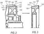
- Figure 2 illustrates a cross sectional view of a portion of the cone brake device 108 ("brake device"), having a brake drum 110
- Figure 3 is a cross-sectional view of a portion of the brake drum 110, illustrating that the brake device 108 has a thermal spray coating 112.
- the thermal spray coating 11 has a thickness of several millimeters.
- the coating 112 is schematically represented by a line in Figure 3 , which is not drawn to scale.
- the exemplary brake device 108 includes an outer member 114, which has an annular inner surface 116.
- the brake device 108 also includes a friction element 118, pad or lining, which is attached to the annular inner surface 116.
- the friction element 118 can be riveted to the outer member 114.
- the friction element 118 can be attached to the outer member 114 by other suitable fasteners and attachment methods.
- the brake drum 110 also has an outer surface 120, and in particular, the brake drum 110 can be a ring 122 having a first end 124 and a second end 126, and the ring can have an outside diameter that tapers from the first end 124 to the second end 126, such that the outer surface 120 of the brake drum 110 is a frustoconical surface 128.
- the thermal sprayed coating 112 is attached to the outer surface 120 of the brake drum 110, and the thermal sprayed coating 112 is configured to engage the friction element 118 when the friction element 118 is moved toward the brake drum 110 so as to contact the same, thus decreasing a speed of the propeller 102.
- the brake device can be configured to move the brake drum toward the friction element so as to decrease propeller speed.
- One example of the coating 112 is a High Velocity Oxygen Fuel (HVOF) coating made of Tungsten Carbide - 17% Cobalt hard material.
- the HVOF coating is applied by a thermal spray coating process in which molten or semi-molten materials are sprayed onto the outer surface 120 by means of the high temperature, high velocity gas stream.
- this process produces a dense spray coating that can be ground to a very high surface finish.
- the HVOF coating 112 has an increased density and hardness, thus increasing resistance to erosion, wear, and corrosion, and maintaining the roughness of the coating 112 over a longer service life of the brake device 108.
- other processes can be utilized for applying the coating to the outer surface.
- the friction element 118 can be made of sintered bronze material.
- Sintering is the process of compacting and forming a solid mass of material by heat and/or pressure without melting it to the point of liquefaction. Sintering happens when the atoms in the materials diffuse across the boundaries of the particles, fusing the particles together and creating one solid piece.
- One exemplary advantage of the sintering process is that it can utilize heat below the melting point of the material, thus reducing manufacturing costs corresponding with materials having considerably high melting points, such as tungsten.
- the sintered material has multiple distinctive structural characteristics. As one example, the sintered material can preserve its purity at least because of the fewer steps in the fabrication process. Furthermore, in the sintering process, there is an absence of binding contact between segregated powder particles or "inclusions," as can often occur in melting processes.
Landscapes
- Engineering & Computer Science (AREA)
- General Engineering & Computer Science (AREA)
- Mechanical Engineering (AREA)
- Aviation & Aerospace Engineering (AREA)
- Chemical & Material Sciences (AREA)
- Inorganic Chemistry (AREA)
- Coating By Spraying Or Casting (AREA)
Description
- The present disclosure relates to gearboxes for aircraft propeller systems and more particularly, but not exclusively, to a gear box having a cone brake device that has a thermal sprayed coating, which has greater hardness so as to increase the service life of the brake device.
- Turboprop manufacturers produce cone brake devices that are configured to slow down the rotation of a propeller during and after engine shutdown. In particular, the typical cone brake device can have an outer surface that is urged into direct contact with an element connected to the propeller. Over the service life of the turboprop, the outer surface can become worn, thus adversely affecting the coefficient of friction at the interface between the outer surface and the component. For this reason, the propeller may freely "windmill" during and after engine shutdown.
- It would therefore be helpful to provide a cone brake device that is configured to slow down rotation of a propeller over a longer service life of the turboprop, thus reducing maintenance of the turboprop and improving overall performance of the same. Related background art can be found in
US 6 119 824 A ,DE 100 35 489 A1WO 2014/097186 A1 ,DE 10 2008 062132 and inDE 2008 035849 A1 . - According to the present disclosure, there is provided a cone brake device and a gear box of an aircraft propeller system, as set forth in the appended claims.
- While the claims are not limited to a specific illustration, an appreciation of the various aspects is best gained through a discussion of various examples thereof. Referring now to the drawings, exemplary illustrations are shown in detail. Although the drawings represent the illustrations, the drawings are not necessarily to scale and certain features may be exaggerated to better illustrate and explain an innovative aspect of an example. Further, the exemplary illustrations described herein are not intended to be exhaustive or otherwise limiting or restricted to the precise form and configuration shown in the drawings and disclosed in the following detailed description. Exemplary illustrations are described in detail by referring to the drawings as follows:
-
FIG. 1 schematically illustrates some aspects of one non-limiting example of an aircraft propeller system including a gear box that has a cone brake device, in accordance with one non-limiting exemplary embodiment of the present disclosure; -
FIG. 2 is a cross-sectional view of one portion of the cone brake device ofFIG. 1 , having a conical drum and a thermal sprayed coating; and -
FIG. 3 is an enlarged view of the conical drum ofFIG. 2 . - An exemplary cone brake device ("brake device") is described herein and shown in the attached drawings. The exemplary brake device is a component of a gear box that is configured to operate a propeller for an aerospace propeller system. The exemplary aerospace propeller system can be a single shaft, modular design military turboprop with a 14 stage axial flow compressor driven by a four stage turbine. However, the cone brake device can instead be a component of other suitable gear boxes for various propulsion or drive mechanisms corresponding with any vehicle. In this example, the cone brake device includes a brake drum and a thermal sprayed coating deposited and bonded to the outer surface of the brake drum. The thermal sprayed coating is configured to engage a friction lining when one of the brake drum and the friction lining is moved toward the other of the brake drum and the friction element, so as to decrease the speed of an aerospace propeller. One exemplary benefit of the thermal sprayed coating is that it maintains its surface roughness and increases the service life of the brake device, thus increasing its overall performance.
- Referring to
Figure 1 , there is illustrated one non-limiting example of anaircraft propeller system 100 having anaerospace propeller 102 and agear box 104, which includes agear set 106 that is connected to thepropeller 102 and configured to rotate the same. Thegear box 104 further includes acone brake device 108, which in this example, is configured to decrease the speed of thepropeller 102. -
Figure 2 illustrates a cross sectional view of a portion of the cone brake device 108 ("brake device"), having abrake drum 110, andFigure 3 is a cross-sectional view of a portion of thebrake drum 110, illustrating that thebrake device 108 has athermal spray coating 112. The thermal spray coating 11 has a thickness of several millimeters. Thus, thecoating 112 is schematically represented by a line inFigure 3 , which is not drawn to scale. - More specifically, as shown in
Figure 2 , theexemplary brake device 108 includes anouter member 114, which has an annularinner surface 116. Thebrake device 108 also includes afriction element 118, pad or lining, which is attached to the annularinner surface 116. Thefriction element 118 can be riveted to theouter member 114. However, thefriction element 118 can be attached to theouter member 114 by other suitable fasteners and attachment methods. Furthermore, thebrake drum 110 also has anouter surface 120, and in particular, thebrake drum 110 can be aring 122 having afirst end 124 and asecond end 126, and the ring can have an outside diameter that tapers from thefirst end 124 to thesecond end 126, such that theouter surface 120 of thebrake drum 110 is afrustoconical surface 128. The thermal sprayedcoating 112 is attached to theouter surface 120 of thebrake drum 110, and the thermal sprayedcoating 112 is configured to engage thefriction element 118 when thefriction element 118 is moved toward thebrake drum 110 so as to contact the same, thus decreasing a speed of thepropeller 102. Of course, another example of the brake device can be configured to move the brake drum toward the friction element so as to decrease propeller speed. One example of thecoating 112 is a High Velocity Oxygen Fuel (HVOF) coating made of Tungsten Carbide - 17% Cobalt hard material. The HVOF coating is applied by a thermal spray coating process in which molten or semi-molten materials are sprayed onto theouter surface 120 by means of the high temperature, high velocity gas stream. In particular, this process produces a dense spray coating that can be ground to a very high surface finish. TheHVOF coating 112 has an increased density and hardness, thus increasing resistance to erosion, wear, and corrosion, and maintaining the roughness of thecoating 112 over a longer service life of thebrake device 108. In other examples, other processes can be utilized for applying the coating to the outer surface. - The
friction element 118 can be made of sintered bronze material. Sintering is the process of compacting and forming a solid mass of material by heat and/or pressure without melting it to the point of liquefaction. Sintering happens when the atoms in the materials diffuse across the boundaries of the particles, fusing the particles together and creating one solid piece. One exemplary advantage of the sintering process is that it can utilize heat below the melting point of the material, thus reducing manufacturing costs corresponding with materials having considerably high melting points, such as tungsten. The sintered material has multiple distinctive structural characteristics. As one example, the sintered material can preserve its purity at least because of the fewer steps in the fabrication process. Furthermore, in the sintering process, there is an absence of binding contact between segregated powder particles or "inclusions," as can often occur in melting processes.
Claims (13)
- A cone brake device (108), comprising:an outer member (114) having an annular inner surface (116);a friction element (118) attached to the annular inner surface (116) of the outer member (114);a brake drum (110) having an outer surface (120) and configured to move toward the friction element (118); anda thermal sprayed coating (112) attached to the outer surface (120) of the brake drum (110) and having a thickness of several millimeters, and the thermal sprayed coating (112) is configured to engage the friction element (118) when one of the brake drum (110) and the friction element (118) is moved toward the other of the brake drum (110) and the friction element (118); wherein the thermal sprayed coating (112) is a tungsten carbide - 17 % cobalt hard material.
- The cone brake device (108) of claim 1, wherein the thermal sprayed coating (112) is a high velocity oxygen fuel coating.
- The cone brake device (108) of claim 1 or 2, wherein the friction element (118) is a sintered bronze material.
- The cone brake device (108) of any one of the preceding claims, wherein the outer surface (120) is a frustoconical surface (128).
- The cone brake device (108) of any one of the preceding claims, wherein the brake drum (110) is a ring (122) having a first end (124, 126) and a second end (124, 126), and the ring (122) has an outside diameter that tapers from the first end (124, 126) to the second end (124, 126).
- The cone brake device (108) of any one of the preceding claims, wherein one of the outer member (114) and the brake drum (110) is connected to an aerospace propeller (102).
- A gear box (104), comprising:a gear set (106); anda cone brake device (108) according to claim 1.
- The gear box (104) of claim 7, wherein the thermal sprayed coating (112) is a high velocity oxygen fuel coating.
- The gear box (104) of of claim 7 or 8, wherein the friction element (118) is a sintered bronze material.
- The gear box (104) of any one of claims 7 to 9, wherein the outer surface (120) is a frustoconical surface (128).
- The gear box (104) of any one of claims 7 to 10, wherein the brake drum (110) is a ring (122) having a first end (124, 126) and a second end (124, 126), and the ring (122) has an outside diameter that tapers from the first end (124, 126) to the second end (124, 126).
- The gear box (104) of any one of claims 7 to 11, wherein one of the outer member (114) and the brake drum (110) is connected to an aerospace propeller (102).
- The gear box (104) of any one of claims 7 to 12, comprising an aircraft propeller system (100), the aircraft propeller system (100) comprising:an aerospace propeller (102);wherein the gear set (106) of the gear box (104) is configured to rotate the aerospace propeller (102);wherein the thermal sprayed coating (112) is configured to engage the friction element (118) when one of the brake drum (110) and the friction element (118) is moved toward the other of the brake drum (110) and the friction element (118), so as to decrease a speed of the aerospace propeller (102).
Applications Claiming Priority (1)
| Application Number | Priority Date | Filing Date | Title |
|---|---|---|---|
| US201562102686P | 2015-01-13 | 2015-01-13 |
Publications (2)
| Publication Number | Publication Date |
|---|---|
| EP3045759A1 EP3045759A1 (en) | 2016-07-20 |
| EP3045759B1 true EP3045759B1 (en) | 2019-07-03 |
Family
ID=55300352
Family Applications (1)
| Application Number | Title | Priority Date | Filing Date |
|---|---|---|---|
| EP16150754.6A Active EP3045759B1 (en) | 2015-01-13 | 2016-01-11 | Cone brake friction surface coating |
Country Status (3)
| Country | Link |
|---|---|
| US (1) | US9995355B2 (en) |
| EP (1) | EP3045759B1 (en) |
| CA (1) | CA2915896C (en) |
Families Citing this family (1)
| Publication number | Priority date | Publication date | Assignee | Title |
|---|---|---|---|---|
| US10626974B2 (en) * | 2013-01-28 | 2020-04-21 | United Technologies Corporation | Structured material alloy component fabrication |
Citations (1)
| Publication number | Priority date | Publication date | Assignee | Title |
|---|---|---|---|---|
| DE102008035849A1 (en) * | 2008-08-01 | 2010-02-04 | Klaus John Eisenmenger | Method for coating a brake area of brake disks or other friction elements of brakes, comprises applying a wear-resistant coating on the brake area through thermal injection |
Family Cites Families (28)
| Publication number | Priority date | Publication date | Assignee | Title |
|---|---|---|---|---|
| US2951540A (en) * | 1956-11-05 | 1960-09-06 | Gen Motors Corp | Propeller brake |
| DE3033139A1 (en) | 1980-09-03 | 1982-04-08 | Alfred Teves Gmbh, 6000 Frankfurt | DEVICE WITH A FRICTION PAIR, IN PARTICULAR FRICTION BRAKE OR FRICTION CLUTCH |
| US4376614A (en) * | 1980-09-29 | 1983-03-15 | The Bendix Corporation | Propeller brake for a turbo-prop engine |
| US4567965A (en) * | 1982-03-22 | 1986-02-04 | Allied Corporation | Propeller brake |
| US4778730A (en) | 1987-09-09 | 1988-10-18 | Remgrit Corporation | Method of applying non-slip coating to tools and resulting product |
| US5203434A (en) * | 1991-06-21 | 1993-04-20 | Dana Corporation | Mounting structure for cone brake |
| JP2992373B2 (en) | 1991-06-21 | 1999-12-20 | 日本ピストンリング株式会社 | Synchronizer ring |
| US5407048A (en) * | 1993-05-04 | 1995-04-18 | Sievers; George K. | High performance automotive clutch assembly |
| FR2717874B1 (en) | 1994-03-25 | 1996-04-26 | Gec Alsthom Transport Sa | Multimaterial disc for high energy braking. |
| US5957251A (en) | 1996-05-02 | 1999-09-28 | The Dow Chemical Company | Brake or clutch components having a ceramic-metal composite friction material |
| US5878849A (en) | 1996-05-02 | 1999-03-09 | The Dow Chemical Company | Ceramic metal composite brake components and manufacture thereof |
| JP3294143B2 (en) | 1996-09-10 | 2002-06-24 | 株式会社東芝 | Brake shoe for elevator emergency stop device, elevator emergency stop device, and elevator having emergency stop function |
| US6129306A (en) * | 1997-03-05 | 2000-10-10 | Pham; Roger N. C. | Easily-convertible high-performance roadable aircraft |
| US5964322A (en) | 1997-11-06 | 1999-10-12 | Otis Elevator Company | Elevator safety brake having a plasma sprayed friction coating |
| US6119824A (en) * | 1998-05-29 | 2000-09-19 | Mccallum; Dennis L. | Braked mechanical joint assembly |
| SE0001255L (en) | 2000-04-04 | 2001-05-07 | Voith Safeset Ab | Coupling device for rapid decoupling of two elements in a transmission |
| DE10035489B4 (en) | 2000-07-21 | 2005-03-17 | Ina-Schaeffler Kg | friction pairing |
| US6619441B2 (en) * | 2001-08-02 | 2003-09-16 | Meritor Heavy Vehicle Technology, Llc | Conical brake assembly |
| FR2851244B1 (en) | 2003-02-17 | 2005-06-17 | Snecma Propulsion Solide | METHOD FOR SILICIURATING THERMOSTRUCTURAL COMPOSITE MATERIALS AND PARTS SUCH AS EXTENDED BY THE PROCESS |
| JP2006153136A (en) * | 2004-11-29 | 2006-06-15 | Toyota Motor Corp | Friction device |
| US7442443B2 (en) * | 2005-05-31 | 2008-10-28 | Goodrich Corporation | Chromium-nickel stainless steel alloy article having oxide coating formed from the base metal suitable for brake apparatus |
| US20060272909A1 (en) | 2005-06-02 | 2006-12-07 | Fuller Brian K | Brake assembly and coating |
| ATE441036T1 (en) * | 2006-04-24 | 2009-09-15 | Gunther Zimmer | BRAKE AND/OR CLAMPING DEVICE FOR SHAFTS WITH A CLAMPING RING |
| JP2010090334A (en) | 2008-10-10 | 2010-04-22 | Toyota Motor Corp | Friction pair |
| DE102008062132A1 (en) | 2008-12-16 | 2010-06-17 | Titan Präcis Metallurgie GmbH | Coating surfaces of brake disks or other friction elements of brakes, comprises roughening the brake surfaces with hard-material granules by radiation, and applying a wear-resistant coating on the brake surfaces by thermal injection |
| EP2935930B1 (en) | 2012-12-21 | 2019-09-18 | Freni Brembo S.p.A. | A method of making a brake disc, brake disc for disc brake and a disc brake |
| US9429227B2 (en) * | 2014-02-19 | 2016-08-30 | Fairfield Manufacturing Company, Inc. | Planetary gearbox with integral service brake |
| EP3028983B1 (en) * | 2014-12-05 | 2018-02-07 | Zollern GmbH & Co. KG | Winch, in particular free fall winch with a service and holding brake |
-
2015
- 2015-12-21 CA CA2915896A patent/CA2915896C/en active Active
-
2016
- 2016-01-08 US US14/991,725 patent/US9995355B2/en active Active
- 2016-01-11 EP EP16150754.6A patent/EP3045759B1/en active Active
Patent Citations (1)
| Publication number | Priority date | Publication date | Assignee | Title |
|---|---|---|---|---|
| DE102008035849A1 (en) * | 2008-08-01 | 2010-02-04 | Klaus John Eisenmenger | Method for coating a brake area of brake disks or other friction elements of brakes, comprises applying a wear-resistant coating on the brake area through thermal injection |
Also Published As
| Publication number | Publication date |
|---|---|
| CA2915896C (en) | 2021-08-03 |
| US9995355B2 (en) | 2018-06-12 |
| EP3045759A1 (en) | 2016-07-20 |
| CA2915896A1 (en) | 2016-07-13 |
| US20160201748A1 (en) | 2016-07-14 |
Similar Documents
| Publication | Publication Date | Title |
|---|---|---|
| EP2574727B1 (en) | Blade air seal with integral thermal barrier corresponding gas turbine engine and method of manufacturing | |
| EP2728119B1 (en) | Microchannel cooled turbine component and method of forming a microchannel cooled turbine component | |
| EP3095965B1 (en) | Gas turbine engine component and corresponding gas turbine engine | |
| EP3591171B1 (en) | Abradable seal including an abradability characteristic that varies by locality | |
| EP3388719A1 (en) | Reduced friction intershaft seal assembly | |
| EP3018296B1 (en) | Gas turbine engine assembly with an abradable blade track and corresponding formation method | |
| US20150184540A1 (en) | System and method for bearings | |
| CN108868902B (en) | Component with co-bonded composite material and metal ring and method of assembling the same | |
| JP2008111191A (en) | Method for depositing abradable material onto seal backing material surface | |
| JP2016098810A (en) | Abradable composition and seal of axial flow turbo machine compressor casing | |
| CA2950549A1 (en) | Metallic attachment system integrated into a composite structure | |
| EP3354883B1 (en) | Locknut sun gear for gas turbine engine | |
| EP3020931B1 (en) | Abrasive rotor coating with rub force limiting features | |
| US20140286756A1 (en) | Device, system and method for preventing leakage in a turbine | |
| US10247027B2 (en) | Outer airseal insulated rub strip | |
| EP3502422A1 (en) | Compressor abradable seal with improved solid lubricant retention | |
| US20100055339A1 (en) | Method of forming molybdenum based wear resistant coating on a workpiece | |
| CA2915896C (en) | Cone brake friction surface coating | |
| US8070435B1 (en) | Split ring wedge bearing damper | |
| EP3456928B1 (en) | Blade outer air seal for gas turbine engines in high erosion environment | |
| US11073186B2 (en) | Brake pad backing plate | |
| RU2368791C2 (en) | System of locking gas turbine engine main shaft by hot-melt bearing | |
| US9863368B1 (en) | Aircraft with gas turbine engine having outer bypass elements removed | |
| EP3872301B1 (en) | Gas turbine rotor component and method of manufacture | |
| CN110049839A (en) | Method for manufacturing gas turbine component |
Legal Events
| Date | Code | Title | Description |
|---|---|---|---|
| PUAI | Public reference made under article 153(3) epc to a published international application that has entered the european phase |
Free format text: ORIGINAL CODE: 0009012 |
|
| AK | Designated contracting states |
Kind code of ref document: A1 Designated state(s): AL AT BE BG CH CY CZ DE DK EE ES FI FR GB GR HR HU IE IS IT LI LT LU LV MC MK MT NL NO PL PT RO RS SE SI SK SM TR |
|
| AX | Request for extension of the european patent |
Extension state: BA ME |
|
| STAA | Information on the status of an ep patent application or granted ep patent |
Free format text: STATUS: REQUEST FOR EXAMINATION WAS MADE |
|
| 17P | Request for examination filed |
Effective date: 20161220 |
|
| RBV | Designated contracting states (corrected) |
Designated state(s): AL AT BE BG CH CY CZ DE DK EE ES FI FR GB GR HR HU IE IS IT LI LT LU LV MC MK MT NL NO PL PT RO RS SE SI SK SM TR |
|
| STAA | Information on the status of an ep patent application or granted ep patent |
Free format text: STATUS: EXAMINATION IS IN PROGRESS |
|
| 17Q | First examination report despatched |
Effective date: 20180525 |
|
| GRAP | Despatch of communication of intention to grant a patent |
Free format text: ORIGINAL CODE: EPIDOSNIGR1 |
|
| STAA | Information on the status of an ep patent application or granted ep patent |
Free format text: STATUS: GRANT OF PATENT IS INTENDED |
|
| INTG | Intention to grant announced |
Effective date: 20190215 |
|
| RIN1 | Information on inventor provided before grant (corrected) |
Inventor name: WINELY, MARK Inventor name: WARRENBURG, SEAN Inventor name: HASSLER, KYLE A. Inventor name: MOCK, KEVIN Inventor name: SWIFT, JOSEPH A. |
|
| GRAS | Grant fee paid |
Free format text: ORIGINAL CODE: EPIDOSNIGR3 |
|
| GRAA | (expected) grant |
Free format text: ORIGINAL CODE: 0009210 |
|
| STAA | Information on the status of an ep patent application or granted ep patent |
Free format text: STATUS: THE PATENT HAS BEEN GRANTED |
|
| AK | Designated contracting states |
Kind code of ref document: B1 Designated state(s): AL AT BE BG CH CY CZ DE DK EE ES FI FR GB GR HR HU IE IS IT LI LT LU LV MC MK MT NL NO PL PT RO RS SE SI SK SM TR |
|
| REG | Reference to a national code |
Ref country code: GB Ref legal event code: FG4D |
|
| REG | Reference to a national code |
Ref country code: CH Ref legal event code: EP Ref country code: AT Ref legal event code: REF Ref document number: 1151377 Country of ref document: AT Kind code of ref document: T Effective date: 20190715 |
|
| REG | Reference to a national code |
Ref country code: DE Ref legal event code: R096 Ref document number: 602016016104 Country of ref document: DE |
|
| REG | Reference to a national code |
Ref country code: IE Ref legal event code: FG4D |
|
| REG | Reference to a national code |
Ref country code: NL Ref legal event code: MP Effective date: 20190703 |
|
| REG | Reference to a national code |
Ref country code: LT Ref legal event code: MG4D |
|
| REG | Reference to a national code |
Ref country code: AT Ref legal event code: MK05 Ref document number: 1151377 Country of ref document: AT Kind code of ref document: T Effective date: 20190703 |
|
| PG25 | Lapsed in a contracting state [announced via postgrant information from national office to epo] |
Ref country code: FI Free format text: LAPSE BECAUSE OF FAILURE TO SUBMIT A TRANSLATION OF THE DESCRIPTION OR TO PAY THE FEE WITHIN THE PRESCRIBED TIME-LIMIT Effective date: 20190703 Ref country code: SE Free format text: LAPSE BECAUSE OF FAILURE TO SUBMIT A TRANSLATION OF THE DESCRIPTION OR TO PAY THE FEE WITHIN THE PRESCRIBED TIME-LIMIT Effective date: 20190703 Ref country code: BG Free format text: LAPSE BECAUSE OF FAILURE TO SUBMIT A TRANSLATION OF THE DESCRIPTION OR TO PAY THE FEE WITHIN THE PRESCRIBED TIME-LIMIT Effective date: 20191003 Ref country code: NO Free format text: LAPSE BECAUSE OF FAILURE TO SUBMIT A TRANSLATION OF THE DESCRIPTION OR TO PAY THE FEE WITHIN THE PRESCRIBED TIME-LIMIT Effective date: 20191003 Ref country code: HR Free format text: LAPSE BECAUSE OF FAILURE TO SUBMIT A TRANSLATION OF THE DESCRIPTION OR TO PAY THE FEE WITHIN THE PRESCRIBED TIME-LIMIT Effective date: 20190703 Ref country code: AT Free format text: LAPSE BECAUSE OF FAILURE TO SUBMIT A TRANSLATION OF THE DESCRIPTION OR TO PAY THE FEE WITHIN THE PRESCRIBED TIME-LIMIT Effective date: 20190703 Ref country code: LT Free format text: LAPSE BECAUSE OF FAILURE TO SUBMIT A TRANSLATION OF THE DESCRIPTION OR TO PAY THE FEE WITHIN THE PRESCRIBED TIME-LIMIT Effective date: 20190703 Ref country code: CZ Free format text: LAPSE BECAUSE OF FAILURE TO SUBMIT A TRANSLATION OF THE DESCRIPTION OR TO PAY THE FEE WITHIN THE PRESCRIBED TIME-LIMIT Effective date: 20190703 Ref country code: PT Free format text: LAPSE BECAUSE OF FAILURE TO SUBMIT A TRANSLATION OF THE DESCRIPTION OR TO PAY THE FEE WITHIN THE PRESCRIBED TIME-LIMIT Effective date: 20191104 Ref country code: NL Free format text: LAPSE BECAUSE OF FAILURE TO SUBMIT A TRANSLATION OF THE DESCRIPTION OR TO PAY THE FEE WITHIN THE PRESCRIBED TIME-LIMIT Effective date: 20190703 |
|
| PG25 | Lapsed in a contracting state [announced via postgrant information from national office to epo] |
Ref country code: AL Free format text: LAPSE BECAUSE OF FAILURE TO SUBMIT A TRANSLATION OF THE DESCRIPTION OR TO PAY THE FEE WITHIN THE PRESCRIBED TIME-LIMIT Effective date: 20190703 Ref country code: LV Free format text: LAPSE BECAUSE OF FAILURE TO SUBMIT A TRANSLATION OF THE DESCRIPTION OR TO PAY THE FEE WITHIN THE PRESCRIBED TIME-LIMIT Effective date: 20190703 Ref country code: ES Free format text: LAPSE BECAUSE OF FAILURE TO SUBMIT A TRANSLATION OF THE DESCRIPTION OR TO PAY THE FEE WITHIN THE PRESCRIBED TIME-LIMIT Effective date: 20190703 Ref country code: RS Free format text: LAPSE BECAUSE OF FAILURE TO SUBMIT A TRANSLATION OF THE DESCRIPTION OR TO PAY THE FEE WITHIN THE PRESCRIBED TIME-LIMIT Effective date: 20190703 Ref country code: GR Free format text: LAPSE BECAUSE OF FAILURE TO SUBMIT A TRANSLATION OF THE DESCRIPTION OR TO PAY THE FEE WITHIN THE PRESCRIBED TIME-LIMIT Effective date: 20191004 Ref country code: IS Free format text: LAPSE BECAUSE OF FAILURE TO SUBMIT A TRANSLATION OF THE DESCRIPTION OR TO PAY THE FEE WITHIN THE PRESCRIBED TIME-LIMIT Effective date: 20191103 |
|
| PG25 | Lapsed in a contracting state [announced via postgrant information from national office to epo] |
Ref country code: TR Free format text: LAPSE BECAUSE OF FAILURE TO SUBMIT A TRANSLATION OF THE DESCRIPTION OR TO PAY THE FEE WITHIN THE PRESCRIBED TIME-LIMIT Effective date: 20190703 |
|
| PG25 | Lapsed in a contracting state [announced via postgrant information from national office to epo] |
Ref country code: RO Free format text: LAPSE BECAUSE OF FAILURE TO SUBMIT A TRANSLATION OF THE DESCRIPTION OR TO PAY THE FEE WITHIN THE PRESCRIBED TIME-LIMIT Effective date: 20190703 Ref country code: PL Free format text: LAPSE BECAUSE OF FAILURE TO SUBMIT A TRANSLATION OF THE DESCRIPTION OR TO PAY THE FEE WITHIN THE PRESCRIBED TIME-LIMIT Effective date: 20190703 Ref country code: DK Free format text: LAPSE BECAUSE OF FAILURE TO SUBMIT A TRANSLATION OF THE DESCRIPTION OR TO PAY THE FEE WITHIN THE PRESCRIBED TIME-LIMIT Effective date: 20190703 Ref country code: IT Free format text: LAPSE BECAUSE OF FAILURE TO SUBMIT A TRANSLATION OF THE DESCRIPTION OR TO PAY THE FEE WITHIN THE PRESCRIBED TIME-LIMIT Effective date: 20190703 Ref country code: EE Free format text: LAPSE BECAUSE OF FAILURE TO SUBMIT A TRANSLATION OF THE DESCRIPTION OR TO PAY THE FEE WITHIN THE PRESCRIBED TIME-LIMIT Effective date: 20190703 |
|
| PG25 | Lapsed in a contracting state [announced via postgrant information from national office to epo] |
Ref country code: SM Free format text: LAPSE BECAUSE OF FAILURE TO SUBMIT A TRANSLATION OF THE DESCRIPTION OR TO PAY THE FEE WITHIN THE PRESCRIBED TIME-LIMIT Effective date: 20190703 Ref country code: IS Free format text: LAPSE BECAUSE OF FAILURE TO SUBMIT A TRANSLATION OF THE DESCRIPTION OR TO PAY THE FEE WITHIN THE PRESCRIBED TIME-LIMIT Effective date: 20200224 Ref country code: SK Free format text: LAPSE BECAUSE OF FAILURE TO SUBMIT A TRANSLATION OF THE DESCRIPTION OR TO PAY THE FEE WITHIN THE PRESCRIBED TIME-LIMIT Effective date: 20190703 |
|
| REG | Reference to a national code |
Ref country code: DE Ref legal event code: R097 Ref document number: 602016016104 Country of ref document: DE |
|
| PLBE | No opposition filed within time limit |
Free format text: ORIGINAL CODE: 0009261 |
|
| STAA | Information on the status of an ep patent application or granted ep patent |
Free format text: STATUS: NO OPPOSITION FILED WITHIN TIME LIMIT |
|
| PG2D | Information on lapse in contracting state deleted |
Ref country code: IS |
|
| 26N | No opposition filed |
Effective date: 20200603 |
|
| PG25 | Lapsed in a contracting state [announced via postgrant information from national office to epo] |
Ref country code: MC Free format text: LAPSE BECAUSE OF FAILURE TO SUBMIT A TRANSLATION OF THE DESCRIPTION OR TO PAY THE FEE WITHIN THE PRESCRIBED TIME-LIMIT Effective date: 20190703 Ref country code: SI Free format text: LAPSE BECAUSE OF FAILURE TO SUBMIT A TRANSLATION OF THE DESCRIPTION OR TO PAY THE FEE WITHIN THE PRESCRIBED TIME-LIMIT Effective date: 20190703 |
|
| REG | Reference to a national code |
Ref country code: CH Ref legal event code: PL |
|
| GBPC | Gb: european patent ceased through non-payment of renewal fee |
Effective date: 20200111 |
|
| REG | Reference to a national code |
Ref country code: BE Ref legal event code: MM Effective date: 20200131 |
|
| PG25 | Lapsed in a contracting state [announced via postgrant information from national office to epo] |
Ref country code: GB Free format text: LAPSE BECAUSE OF NON-PAYMENT OF DUE FEES Effective date: 20200111 Ref country code: LU Free format text: LAPSE BECAUSE OF NON-PAYMENT OF DUE FEES Effective date: 20200111 |
|
| PG25 | Lapsed in a contracting state [announced via postgrant information from national office to epo] |
Ref country code: CH Free format text: LAPSE BECAUSE OF NON-PAYMENT OF DUE FEES Effective date: 20200131 Ref country code: BE Free format text: LAPSE BECAUSE OF NON-PAYMENT OF DUE FEES Effective date: 20200131 Ref country code: LI Free format text: LAPSE BECAUSE OF NON-PAYMENT OF DUE FEES Effective date: 20200131 |
|
| PG25 | Lapsed in a contracting state [announced via postgrant information from national office to epo] |
Ref country code: IE Free format text: LAPSE BECAUSE OF NON-PAYMENT OF DUE FEES Effective date: 20200111 |
|
| PG25 | Lapsed in a contracting state [announced via postgrant information from national office to epo] |
Ref country code: MT Free format text: LAPSE BECAUSE OF FAILURE TO SUBMIT A TRANSLATION OF THE DESCRIPTION OR TO PAY THE FEE WITHIN THE PRESCRIBED TIME-LIMIT Effective date: 20190703 Ref country code: CY Free format text: LAPSE BECAUSE OF FAILURE TO SUBMIT A TRANSLATION OF THE DESCRIPTION OR TO PAY THE FEE WITHIN THE PRESCRIBED TIME-LIMIT Effective date: 20190703 |
|
| PG25 | Lapsed in a contracting state [announced via postgrant information from national office to epo] |
Ref country code: MK Free format text: LAPSE BECAUSE OF FAILURE TO SUBMIT A TRANSLATION OF THE DESCRIPTION OR TO PAY THE FEE WITHIN THE PRESCRIBED TIME-LIMIT Effective date: 20190703 |
|
| P01 | Opt-out of the competence of the unified patent court (upc) registered |
Effective date: 20230528 |
|
| PGFP | Annual fee paid to national office [announced via postgrant information from national office to epo] |
Ref country code: DE Payment date: 20260127 Year of fee payment: 11 |
|
| PGFP | Annual fee paid to national office [announced via postgrant information from national office to epo] |
Ref country code: FR Payment date: 20260126 Year of fee payment: 11 |