EP3045698A1 - Vorrichtung und verfahren zur rückgewinnung von in verbrennungsgasen enthaltener wärme - Google Patents
Vorrichtung und verfahren zur rückgewinnung von in verbrennungsgasen enthaltener wärme Download PDFInfo
- Publication number
- EP3045698A1 EP3045698A1 EP15201950.1A EP15201950A EP3045698A1 EP 3045698 A1 EP3045698 A1 EP 3045698A1 EP 15201950 A EP15201950 A EP 15201950A EP 3045698 A1 EP3045698 A1 EP 3045698A1
- Authority
- EP
- European Patent Office
- Prior art keywords
- gases
- combustion gases
- heat
- hot
- cold
- Prior art date
- Legal status (The legal status is an assumption and is not a legal conclusion. Google has not performed a legal analysis and makes no representation as to the accuracy of the status listed.)
- Granted
Links
- 239000000567 combustion gas Substances 0.000 title claims abstract description 48
- 238000000034 method Methods 0.000 title claims abstract description 19
- 239000007789 gas Substances 0.000 claims abstract description 46
- 238000011144 upstream manufacturing Methods 0.000 claims abstract description 13
- 239000002826 coolant Substances 0.000 claims abstract description 8
- 238000011084 recovery Methods 0.000 claims description 18
- 238000007906 compression Methods 0.000 claims description 14
- 230000006835 compression Effects 0.000 claims description 14
- 239000013529 heat transfer fluid Substances 0.000 claims description 12
- 238000009833 condensation Methods 0.000 claims description 10
- 230000005494 condensation Effects 0.000 claims description 10
- 239000012530 fluid Substances 0.000 claims description 9
- 238000009826 distribution Methods 0.000 claims description 7
- 230000001105 regulatory effect Effects 0.000 claims description 7
- 239000003344 environmental pollutant Substances 0.000 claims description 6
- 231100000719 pollutant Toxicity 0.000 claims description 6
- 238000001816 cooling Methods 0.000 claims description 4
- UFHFLCQGNIYNRP-UHFFFAOYSA-N Hydrogen Chemical compound [H][H] UFHFLCQGNIYNRP-UHFFFAOYSA-N 0.000 claims description 3
- 229910052739 hydrogen Inorganic materials 0.000 claims description 3
- 239000001257 hydrogen Substances 0.000 claims description 3
- 230000003472 neutralizing effect Effects 0.000 claims description 2
- 238000013021 overheating Methods 0.000 claims description 2
- 238000007599 discharging Methods 0.000 claims 2
- XLYOFNOQVPJJNP-UHFFFAOYSA-N water Chemical compound O XLYOFNOQVPJJNP-UHFFFAOYSA-N 0.000 description 23
- 238000002485 combustion reaction Methods 0.000 description 9
- 239000003570 air Substances 0.000 description 7
- 239000003546 flue gas Substances 0.000 description 5
- 230000008901 benefit Effects 0.000 description 4
- 239000000446 fuel Substances 0.000 description 4
- 239000003517 fume Substances 0.000 description 4
- 238000009434 installation Methods 0.000 description 4
- 238000004519 manufacturing process Methods 0.000 description 4
- UGFAIRIUMAVXCW-UHFFFAOYSA-N Carbon monoxide Chemical compound [O+]#[C-] UGFAIRIUMAVXCW-UHFFFAOYSA-N 0.000 description 3
- 238000013461 design Methods 0.000 description 3
- 239000007788 liquid Substances 0.000 description 3
- 239000000463 material Substances 0.000 description 3
- 230000003750 conditioning effect Effects 0.000 description 2
- 238000009795 derivation Methods 0.000 description 2
- 239000006185 dispersion Substances 0.000 description 2
- 238000010438 heat treatment Methods 0.000 description 2
- 239000008236 heating water Substances 0.000 description 2
- 238000005457 optimization Methods 0.000 description 2
- 239000003507 refrigerant Substances 0.000 description 2
- 238000012546 transfer Methods 0.000 description 2
- 238000013022 venting Methods 0.000 description 2
- 239000002028 Biomass Substances 0.000 description 1
- OKTJSMMVPCPJKN-UHFFFAOYSA-N Carbon Chemical compound [C] OKTJSMMVPCPJKN-UHFFFAOYSA-N 0.000 description 1
- 229920001875 Ebonite Polymers 0.000 description 1
- RRHGJUQNOFWUDK-UHFFFAOYSA-N Isoprene Chemical compound CC(=C)C=C RRHGJUQNOFWUDK-UHFFFAOYSA-N 0.000 description 1
- 229920000271 Kevlar® Polymers 0.000 description 1
- 239000004809 Teflon Substances 0.000 description 1
- 229920006362 Teflon® Polymers 0.000 description 1
- 239000002253 acid Substances 0.000 description 1
- 230000006978 adaptation Effects 0.000 description 1
- 239000012080 ambient air Substances 0.000 description 1
- 238000004458 analytical method Methods 0.000 description 1
- 238000013459 approach Methods 0.000 description 1
- 229910052799 carbon Inorganic materials 0.000 description 1
- 229910002091 carbon monoxide Inorganic materials 0.000 description 1
- 230000015556 catabolic process Effects 0.000 description 1
- 239000000919 ceramic Substances 0.000 description 1
- 230000005465 channeling Effects 0.000 description 1
- 238000001311 chemical methods and process Methods 0.000 description 1
- 239000003153 chemical reaction reagent Substances 0.000 description 1
- 150000001805 chlorine compounds Chemical class 0.000 description 1
- 238000000576 coating method Methods 0.000 description 1
- 230000001143 conditioned effect Effects 0.000 description 1
- 238000005260 corrosion Methods 0.000 description 1
- 230000007797 corrosion Effects 0.000 description 1
- 238000006731 degradation reaction Methods 0.000 description 1
- 238000010790 dilution Methods 0.000 description 1
- 239000012895 dilution Substances 0.000 description 1
- 230000008034 disappearance Effects 0.000 description 1
- 239000010791 domestic waste Substances 0.000 description 1
- 238000005516 engineering process Methods 0.000 description 1
- 230000006870 function Effects 0.000 description 1
- 239000011521 glass Substances 0.000 description 1
- 229910001385 heavy metal Inorganic materials 0.000 description 1
- 239000004761 kevlar Substances 0.000 description 1
- 238000002156 mixing Methods 0.000 description 1
- 239000007800 oxidant agent Substances 0.000 description 1
- 230000001590 oxidative effect Effects 0.000 description 1
- 239000002245 particle Substances 0.000 description 1
- 229920001343 polytetrafluoroethylene Polymers 0.000 description 1
- 239000004810 polytetrafluoroethylene Substances 0.000 description 1
- 238000003825 pressing Methods 0.000 description 1
- 238000000746 purification Methods 0.000 description 1
- 238000009738 saturating Methods 0.000 description 1
- 238000007789 sealing Methods 0.000 description 1
- 230000001932 seasonal effect Effects 0.000 description 1
- 238000009491 slugging Methods 0.000 description 1
- 239000000779 smoke Substances 0.000 description 1
- 150000003464 sulfur compounds Chemical class 0.000 description 1
- 238000005406 washing Methods 0.000 description 1
- 239000002351 wastewater Substances 0.000 description 1
- 239000002023 wood Substances 0.000 description 1
Images
Classifications
-
- F—MECHANICAL ENGINEERING; LIGHTING; HEATING; WEAPONS; BLASTING
- F02—COMBUSTION ENGINES; HOT-GAS OR COMBUSTION-PRODUCT ENGINE PLANTS
- F02C—GAS-TURBINE PLANTS; AIR INTAKES FOR JET-PROPULSION PLANTS; CONTROLLING FUEL SUPPLY IN AIR-BREATHING JET-PROPULSION PLANTS
- F02C6/00—Plural gas-turbine plants; Combinations of gas-turbine plants with other apparatus; Adaptations of gas-turbine plants for special use
- F02C6/18—Plural gas-turbine plants; Combinations of gas-turbine plants with other apparatus; Adaptations of gas-turbine plants for special use using the waste heat of gas-turbine plants outside the plants themselves, e.g. gas-turbine power heat plants
-
- B—PERFORMING OPERATIONS; TRANSPORTING
- B01—PHYSICAL OR CHEMICAL PROCESSES OR APPARATUS IN GENERAL
- B01D—SEPARATION
- B01D53/00—Separation of gases or vapours; Recovering vapours of volatile solvents from gases; Chemical or biological purification of waste gases, e.g. engine exhaust gases, smoke, fumes, flue gases, aerosols
- B01D53/26—Drying gases or vapours
- B01D53/265—Drying gases or vapours by refrigeration (condensation)
-
- F—MECHANICAL ENGINEERING; LIGHTING; HEATING; WEAPONS; BLASTING
- F23—COMBUSTION APPARATUS; COMBUSTION PROCESSES
- F23J—REMOVAL OR TREATMENT OF COMBUSTION PRODUCTS OR COMBUSTION RESIDUES; FLUES
- F23J15/00—Arrangements of devices for treating smoke or fumes
- F23J15/06—Arrangements of devices for treating smoke or fumes of coolers
-
- F—MECHANICAL ENGINEERING; LIGHTING; HEATING; WEAPONS; BLASTING
- F23—COMBUSTION APPARATUS; COMBUSTION PROCESSES
- F23J—REMOVAL OR TREATMENT OF COMBUSTION PRODUCTS OR COMBUSTION RESIDUES; FLUES
- F23J15/00—Arrangements of devices for treating smoke or fumes
- F23J15/08—Arrangements of devices for treating smoke or fumes of heaters
-
- B—PERFORMING OPERATIONS; TRANSPORTING
- B01—PHYSICAL OR CHEMICAL PROCESSES OR APPARATUS IN GENERAL
- B01D—SEPARATION
- B01D2257/00—Components to be removed
- B01D2257/20—Halogens or halogen compounds
-
- B—PERFORMING OPERATIONS; TRANSPORTING
- B01—PHYSICAL OR CHEMICAL PROCESSES OR APPARATUS IN GENERAL
- B01D—SEPARATION
- B01D2257/00—Components to be removed
- B01D2257/30—Sulfur compounds
-
- B—PERFORMING OPERATIONS; TRANSPORTING
- B01—PHYSICAL OR CHEMICAL PROCESSES OR APPARATUS IN GENERAL
- B01D—SEPARATION
- B01D2257/00—Components to be removed
- B01D2257/60—Heavy metals or heavy metal compounds
-
- B—PERFORMING OPERATIONS; TRANSPORTING
- B01—PHYSICAL OR CHEMICAL PROCESSES OR APPARATUS IN GENERAL
- B01D—SEPARATION
- B01D2258/00—Sources of waste gases
- B01D2258/02—Other waste gases
- B01D2258/0283—Flue gases
-
- F—MECHANICAL ENGINEERING; LIGHTING; HEATING; WEAPONS; BLASTING
- F05—INDEXING SCHEMES RELATING TO ENGINES OR PUMPS IN VARIOUS SUBCLASSES OF CLASSES F01-F04
- F05D—INDEXING SCHEME FOR ASPECTS RELATING TO NON-POSITIVE-DISPLACEMENT MACHINES OR ENGINES, GAS-TURBINES OR JET-PROPULSION PLANTS
- F05D2260/00—Function
- F05D2260/20—Heat transfer, e.g. cooling
- F05D2260/213—Heat transfer, e.g. cooling by the provision of a heat exchanger within the cooling circuit
-
- F—MECHANICAL ENGINEERING; LIGHTING; HEATING; WEAPONS; BLASTING
- F05—INDEXING SCHEMES RELATING TO ENGINES OR PUMPS IN VARIOUS SUBCLASSES OF CLASSES F01-F04
- F05D—INDEXING SCHEME FOR ASPECTS RELATING TO NON-POSITIVE-DISPLACEMENT MACHINES OR ENGINES, GAS-TURBINES OR JET-PROPULSION PLANTS
- F05D2260/00—Function
- F05D2260/60—Fluid transfer
-
- F—MECHANICAL ENGINEERING; LIGHTING; HEATING; WEAPONS; BLASTING
- F23—COMBUSTION APPARATUS; COMBUSTION PROCESSES
- F23J—REMOVAL OR TREATMENT OF COMBUSTION PRODUCTS OR COMBUSTION RESIDUES; FLUES
- F23J2219/00—Treatment devices
- F23J2219/70—Condensing contaminants with coolers
-
- Y—GENERAL TAGGING OF NEW TECHNOLOGICAL DEVELOPMENTS; GENERAL TAGGING OF CROSS-SECTIONAL TECHNOLOGIES SPANNING OVER SEVERAL SECTIONS OF THE IPC; TECHNICAL SUBJECTS COVERED BY FORMER USPC CROSS-REFERENCE ART COLLECTIONS [XRACs] AND DIGESTS
- Y02—TECHNOLOGIES OR APPLICATIONS FOR MITIGATION OR ADAPTATION AGAINST CLIMATE CHANGE
- Y02E—REDUCTION OF GREENHOUSE GAS [GHG] EMISSIONS, RELATED TO ENERGY GENERATION, TRANSMISSION OR DISTRIBUTION
- Y02E20/00—Combustion technologies with mitigation potential
- Y02E20/30—Technologies for a more efficient combustion or heat usage
Definitions
- the invention relates to the field of heat recovery and more specifically to the latent and sensible heat contained in combustion gases.
- the purification of combustion gases containing a certain moisture content is further concerned by the invention.
- the combustion gases are the gases resulting from combustion.
- H + 2O H2O. Since the air is taken as oxidant, there is presence of water vapor contained in the air according to the hydrometry thereof. And when there is water in the fuel (wood, biomass, household waste), there is presence of water vapor in the smoke or gas from combustion.
- Carnot cycles are known for thermal and steam turbines, Otto's cycles for thermal compression engines, baritone for gas turbines, Rankine and Ericsson for Sterling engines.
- the prior art is not specifically interested in the compression of the combustion gases to recover the maximum latent heat. This problem is treated at the margin, for specific industrial installations whose primary purpose is not necessarily to condense and recover the latent heat of the combustion gases. Energy gains related to such a recovery of energy seem however interesting as will be explained below.
- the invention aims to overcome the disadvantages of the state of the art and in particular has the advantage of recovering a maximum of latent and sensitive heat by conditioning the combustion gases, to transfer latent heat and sensitive to a heat transfer fluid, to be used or valued, as explained in more detail below.
- recovering a maximum of latent and sensible heat means a recovery of the order of 100% of the Higher Caloric Power - PCI-; this is notably due to the fact that the present invention makes it possible to recover a significant part of the latent heat of the water contained in the air.
- latent and sensible heat corresponds to the usual meaning of thermodynamics.
- a device for recovering heat contained in combustion gases is proposed according to a first aspect of the invention; the device is characterized in that it comprises: a primary circuit in which the combustion gases circulate and comprising in the flow direction of said gases: - an enclosure for the input of said combustion gases; - a sealed pressure chamber equipped with a compressor; a cold medium on which an exchange of heat with said gases takes place in order to recover the heat beyond the PCS; - Sower type adjustment means adapted to adapt and regulate the pressure loss created upstream; a condensate recuperator placed under said cold medium and cooperating with an expansion member or a pump, and an evacuation means; a hot medium capable of increasing the temperature of said gases; - an outlet for treated and dry combustion gases; the device according to the invention further comprises a secondary circuit comprising means for circulating a heat transfer fluid through said cold medium, said hot medium.
- said primary circuit further comprises an overheating means, at least one distribution valve being placed downstream of said cold medium and upstream of the superheating means relative to the flow direction of said heat transfer fluid in the device, said valve distribution allowing a controlled derivation of said heat transfer fluid vis-à-vis said hot media.
- coolant covers all liquids and gases that can be used for "maximum” recovery of latent heat. and sensitive contained in the combustion gases of a fuel taken at its higher calorific value (PCS), and whose products of combustion are brought back to 0 ° Celsius.
- PCS calorific value
- this abuse of language encountered in the literature omits the fact that internal energy is contained in the material to zero absolute 0 ° Kelvin, or -273 ° Celsius.
- specific heat transfer fluids in particular refrigerants
- PCS higher calorific value
- cold media includes heat exchangers, boiler bodies, ducts, pipes and chimneys capable of serving as a cold surface for energy recovery.
- said primary circuit may comprise a hot medium capable of increasing the temperature of said gases, said hot medium being placed close to the output enclosure.
- the device further comprises a means adapted to avoid the entrainment of the droplets present in the combustion gases, such as a droplet separator disposed (s) between the cold medium and the hot media.
- said droplet separator is placed upstream of said charge control means.
- Way to Charge regulation can consist of sashes, which otherwise can be regulated to improve energy recovery.
- said distribution valve allows a controlled (partial or total) derivation of said heat transfer fluid vis-à-vis said hot media.
- This alternative is advantageous when it is necessary to increase the temperature of the gases leaving the droplet separator, in particular to comply with certain conditions for venting the combustion gases (temperature, speed, density).
- said cold medium comprises a tubular exchanger of the counter-current or cross-current type.
- the device according to the invention may comprise a thermodynamic heat pump placed upstream of said cold medium or close to the condensate discharge means in order to optimize the heat recovery from the combustion gases.
- the device comprises a means capable of neutralizing the hydrogen potential (pH) placed either in the sealed enclosure, or downstream of the condensate expansion device, or upstream of said pump to heat when the heat pump is placed near the condensate discharge means.
- pH hydrogen potential
- the device according to the invention may comprise a means for capturing pollutants present in said condensates.
- the invention further relates to a method of recovering heat contained in hot combustion gases.
- the method is carried out using a device as claimed and comprises the steps of: a) in the primary circuit - compressing said combustion gases; condensing the moisture contained in said gases at a temperature above the condensation temperature of the uncompressed gases; - Collect the condensates from said condensation; - extract the pollutants present in condensates; b) in the secondary circuit - circulating a heat transfer fluid in order in particular to condense the moisture, to heat said condensed gases.
- the method makes it possible to superheat said heat transfer fluid by cooling said gases before compressing them.
- the method according to the invention further comprises regulating said compression of the combustion gases either directly at said compressor or by acting on the adjusting means adapted to regulate said pressure drop.
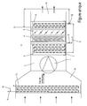
- the single figure shows the device or installation schematically. It shows the essential structural and functional elements of the invention which comprise a so-called primary circuit associated with the flow of the combustion gases to be treated, and a so-called secondary circuit corresponding to the circulation of the coolant such as water, a refrigerant or organic fluid.
- the hot gases to be treated open out according to the arrows on the left side of the figure, in an inlet conduit 14.
- the temperature of said gases may be usually between 100 ° C and 300 ° C.
- the gases can, if necessary, pass through a superheater 13 placed in the duct 14, upstream of a pressurized sealed enclosure 2 which is provided with a compressor 1.
- the compressor 1 transmits to the hot gases a pressure close to the saturation partial pressure. water vapor; This pressure varies depending on the temperature of the hot gases and their moisture content.
- the skilled person determines the compression of the hot gases most appropriate, and it regulates including varying the rotational speed of said compressor 1 and / or 5 adjustable blades provided for this purpose.
- the pressure in the chamber 2 may be between 2 and 10 bar absolute.
- the “saturation partial pressure of water vapor” is the pressure at which the water vapor contained in the compression gases begins to condense, for a given temperature and water content (ie relative humidity, in absolute humidity).
- the compressor 1 and / or the sails 5 act on this pressure.
- the combustion gases are directed to a cold medium 3, of the counter-current or cross-flow exchanger type, in order to continuously lower the temperatures of said gases, up to at a minimum temperature at the output of the media 2.
- the temperature drop can vary from 10% to 90% between the input and the output of the medium 2.
- pressurized sealed enclosure is meant a chamber provided with a seal vis-à-vis the outside of the device, regardless of the temperatures and pressures involved.
- the pressures in the chamber 2 can vary between 2 and 10 bar absolute, and the operating temperatures between 100 and 300 degrees Celsius at the inlet gas, and with lower temperatures or even negative output of the cold media. Applying pressure to hot gases alters the saturation vapor pressure value and tends to initiate condensation at higher temperatures. It is interesting to note that instantaneous performance can produce more condensate and recover more latent energy.
- the method associated with the device according to the invention can improve performance because in known manner, these performances are limited (especially for domestic boilers) by the return temperature of the heating water, conditioned by the season of the year; for the production of hot water the performances are limited by the production temperature of the domestic hot water.
- a droplet separator 4 capable of keeping the cold media 3 under pressure and of preventing the particles contained in the gases downstream of the device from being driven.
- the separator 4 constitutes a pressure drop that is additional to that created by the cold medium 3.
- pressure drops are usually to be avoided, it is possible to use other systems capable of preventing the entrainment of the droplets, such as, for example a circular deflector with variable diameter.
- the sashes 5 can be installed complementarily; the sails 5 can be regulated in different ways to optimize the energy recovery.
- the sashes may be replaced by any other means for varying the pressure drop at the outlet of the cold medium 3, such as for example a circular baffle with variable passage diameter.
- the device and the method according to the invention generally make it possible to increase the energy recovery contained in the combustion gases, in particular that dissipated during the condensation of the water vapor in them, as a function of the pressure of saturating vapor in the pressure vessel 2. It is therefore advantageous to control the slugging of the pressure drop in order to maintain a certain pressure drop, especially in the cold media 3, that is to say a pressure, capable of maintaining the performance of the invention, whatever the external conditions or the appearance of the heating equipment in which the device according to the invention is arranged.
- a certain pressure drop especially in the cold media 3, that is to say a pressure, capable of maintaining the performance of the invention, whatever the external conditions or the appearance of the heating equipment in which the device according to the invention is arranged.
- a hot medium 6 capable of raising the temperature of the gases from the cold media.
- the presence of the hot media 6 also improves the dispersion of gases in the atmosphere downstream, which are very slightly moist and slightly heavier. It is well known that humid air is lighter than dry air; the hot media 6, which elevates the gas temperature, makes them lighter, therefore more bulky and have excellent dispersion.
- a tray 7 condensate recovery sized to recover all the condensate, depending on the flow and the humidity of the combustion gases, as well as according to the allowable flow rate of water at an expansion member or a pump 8 or depressor element; the tank 7 advantageously allows the recovery of the condensates before their regulation through the expansion member or the pump 8.
- the condensates are then directed to the means 9, low pressure and leak-free outside the speakers 14, 2.
- the method associated with the device makes it possible to use (or even to get rid of) the gas exhaust duct 10 usually present, located downstream of the sealed enclosure 2 under pressure.
- the extension of the sealed chamber 2 under pressure significantly reduces the useful diameter of the conduit 10 until venting (chimney) or any other outlet.
- the present invention perfectly meets the speeds and temperatures imposed by the standards for industrial installations, the need for a perfect seal, and the generation of a reduced plume of clean fumes output of the device.
- the device according to the invention further comprises a secondary circuit for a heat transfer fluid supplied with cold fluid; the cold fluid arrives at the level of the cold medium 3 (arrival 11), circulates in the cold medium 3 where it slowly warms up.
- the cold fluid has a pressure and a flow rate controlled in particular for a possible change of state at a given temperature; at the outlet of the cold medium 3, the coolant is optionally directed to a distribution valve 12, or to valves in opposite directions, to supply on demand (if required) the hot medium 6, which after the mixing point feeds a superheater 13 (if present).
- the distribution valve 12 allows the liquid leaving the cold medium 3 to bypass the hot medium 6 to, for example, directly feed the superheater 13 of the coolant 11.
- its phase change liquid to vapor
- the coolant having or not passed through the hot medium 6, is preferably directed towards the superheater 13 which is disposed in the conduit 14 of arrival of the combustion gases.
- the superheater 13, here arranged in the inlet duct 14, makes it possible to supply superheated steam at its secondary fluidic outlet 15, to a specific assembly (of the turbine-type, Rankin cycle, thermodynamic heat pump, use of steam live or other) or a heat network.
- desuperheating associated with a desuperheating means 16 may in particular be provided.
- the conditioning of the steam delivered at the output of the secondary circuit is a preponderant factor in the design of the device according to the invention, particularly as regards its dimensioning; in addition, the power requirements, temperatures of the elements upstream of the device, condition its design.
- the combustion gases leaving the pressurized watertight enclosure 10 are rid of numerous atmospheric pollutants (sulfur compounds, chlorine compounds, heavy metals, dusts, etc.), which are found in the evacuation of the condensates 9 and are easily treatable after the pH has been neutralized.
- a heat pump (not shown in the single figure) can lower the condensate temperature and recover an easily recoverable energy.
- the condensates can then be treated and potentially prepared in boiler water for steam production in open circuit, or they can be reinjected at the cold fluid 11 if the cold fluid is water. If necessary, these condensates are evacuated to an outlet type network of wastewater or natural environment.
- the cold fluid can have negative temperatures and thus allow the almost total recovery of the power Higher calorific value (PCS) of the fuel in question, then to be efficientlysed in vapor or in any other form.
- PCS Higher calorific value
- the device according to the invention as well as the method used make it possible to trap in the condensates collected in the tank 7, a certain number of pollutants, while compressing the combustion gases in order to extract the maximum of sensible energy and the tent.
- the invention covers the method implemented by the device described above, structurally and functionally.
- the device according to the invention can be implanted on existing installations, the combustion gases are in depression or slight overpressure. It is always a matter of maintaining a given pressure upstream of the compressor 1, so as to comply with the standards or constraints provided by the manufacturer of the combustion means.
- the present invention makes it possible to condition the gases resulting from the combustion by compressing them, before proceeding with the energy recovery and / or the depollution of the pollutants present in the condensates collected.
- the compression and cooling of the exhaust gas can be mounted in successive cascades so as to obtain perfectly dry gases.
Landscapes
- Engineering & Computer Science (AREA)
- Mechanical Engineering (AREA)
- Chemical & Material Sciences (AREA)
- General Engineering & Computer Science (AREA)
- Thermal Sciences (AREA)
- Analytical Chemistry (AREA)
- General Chemical & Material Sciences (AREA)
- Oil, Petroleum & Natural Gas (AREA)
- Chemical Kinetics & Catalysis (AREA)
- Combustion & Propulsion (AREA)
- Physics & Mathematics (AREA)
- Treating Waste Gases (AREA)
- Engine Equipment That Uses Special Cycles (AREA)
- Incineration Of Waste (AREA)
Applications Claiming Priority (1)
| Application Number | Priority Date | Filing Date | Title |
|---|---|---|---|
| FR1500097A FR3031766A1 (fr) | 2015-01-19 | 2015-01-19 | Procede et installation de recuperation de chaleur et de traitement des gaz de combustion |
Publications (2)
| Publication Number | Publication Date |
|---|---|
| EP3045698A1 true EP3045698A1 (de) | 2016-07-20 |
| EP3045698B1 EP3045698B1 (de) | 2018-11-14 |
Family
ID=55527191
Family Applications (1)
| Application Number | Title | Priority Date | Filing Date |
|---|---|---|---|
| EP15201950.1A Active EP3045698B1 (de) | 2015-01-19 | 2015-12-22 | Vorrichtung und verfahren zur rückgewinnung von in verbrennungsgasen enthaltener wärme |
Country Status (2)
| Country | Link |
|---|---|
| EP (1) | EP3045698B1 (de) |
| FR (1) | FR3031766A1 (de) |
Cited By (2)
| Publication number | Priority date | Publication date | Assignee | Title |
|---|---|---|---|---|
| WO2018013394A3 (en) * | 2016-07-14 | 2018-02-08 | General Electric Company | Entrainment heat exchanger |
| CN108543326A (zh) * | 2018-04-03 | 2018-09-18 | 杭州精湛科技咨询有限责任公司 | 消白烟装置和消白烟方法 |
Citations (3)
| Publication number | Priority date | Publication date | Assignee | Title |
|---|---|---|---|---|
| US4126000A (en) * | 1972-05-12 | 1978-11-21 | Funk Harald F | System for treating and recovering energy from exhaust gases |
| US20040253165A1 (en) * | 2003-06-10 | 2004-12-16 | Yves Charron | Fumes treating process with energy recovery |
| US20120037096A1 (en) * | 2010-08-16 | 2012-02-16 | Takagi Industrial Co., Ltd. | Combustion apparatus, method for combustion control, combustion control board, combustion control system and water heater |
-
2015
- 2015-01-19 FR FR1500097A patent/FR3031766A1/fr not_active Withdrawn
- 2015-12-22 EP EP15201950.1A patent/EP3045698B1/de active Active
Patent Citations (3)
| Publication number | Priority date | Publication date | Assignee | Title |
|---|---|---|---|---|
| US4126000A (en) * | 1972-05-12 | 1978-11-21 | Funk Harald F | System for treating and recovering energy from exhaust gases |
| US20040253165A1 (en) * | 2003-06-10 | 2004-12-16 | Yves Charron | Fumes treating process with energy recovery |
| US20120037096A1 (en) * | 2010-08-16 | 2012-02-16 | Takagi Industrial Co., Ltd. | Combustion apparatus, method for combustion control, combustion control board, combustion control system and water heater |
Cited By (4)
| Publication number | Priority date | Publication date | Assignee | Title |
|---|---|---|---|---|
| WO2018013394A3 (en) * | 2016-07-14 | 2018-02-08 | General Electric Company | Entrainment heat exchanger |
| US11168951B2 (en) | 2016-07-14 | 2021-11-09 | General Electric Company | Entrainment heat exchanger |
| CN108543326A (zh) * | 2018-04-03 | 2018-09-18 | 杭州精湛科技咨询有限责任公司 | 消白烟装置和消白烟方法 |
| CN108543326B (zh) * | 2018-04-03 | 2019-10-25 | 杭州精湛科技咨询有限责任公司 | 消白烟装置和消白烟方法 |
Also Published As
| Publication number | Publication date |
|---|---|
| FR3031766A1 (fr) | 2016-07-22 |
| EP3045698B1 (de) | 2018-11-14 |
Similar Documents
| Publication | Publication Date | Title |
|---|---|---|
| CA2859748C (fr) | Procede et installation de cogeneration. | |
| FR2966877A1 (fr) | Centrale electrique a cycle combine avec echangeur de chaleur | |
| FR2781252A1 (fr) | Centrale electrique mixte | |
| FR2961851A1 (fr) | Systeme comprenant un rechauffeur d'eau d'alimentation pour extraire de la chaleur d'une turbine a vapeur a basse pression | |
| FR2910112A1 (fr) | Procede pour faire fonctionner une centrale thermique a vapeur au charbon, ainsi que centrale a vapeur | |
| FR2973073A1 (fr) | Centrale a cycle combine | |
| FR2576968A1 (fr) | Procede et dispositif pour l'exploitation d'une centrale electrique | |
| EP3045698B1 (de) | Vorrichtung und verfahren zur rückgewinnung von in verbrennungsgasen enthaltener wärme | |
| FR2979974A3 (fr) | Procede et systeme de traitement de gaz de combustion d'une source de chaleur | |
| FR3001768A1 (fr) | Installation a turbine a gaz et procede de regulation de ladite installation | |
| EP3004571B1 (de) | Verfahren zur energieerzeugung durch verbrennung von stoffen sowie anlage zur durchführung des verfahrens | |
| FR2979138A1 (fr) | Installation de cogeneration a partir de biomasse | |
| FR3011917A1 (fr) | Procede et installation de recuperation de chaleur sur des fumees humides | |
| EP2918911B1 (de) | Verbrennungsprozess in thermischer Verbrennungsanlage | |
| BE1026742B1 (fr) | Procédé de transfert d'énergie de condensation de la vapeur d'eau de fumées de cogénération | |
| FR2921717A1 (fr) | Dispositif de recuperation de calories des gaz chauds dans une installation de chauffage avec une chaudiere | |
| FR2983901A1 (fr) | Installation thermique de production d' electricite | |
| Ganassin et al. | Small scale solid biomass fuelled ORC plants for combined heat and power | |
| EP3060846B1 (de) | Verfahren und einrichtung zur energiegewinnung aus abfällen | |
| FR3055154A3 (fr) | Installation de chauffage a conduits radiants | |
| FR3005143A1 (fr) | Installation thermique de production d'electricite par combustion | |
| RU2007132777A (ru) | Парогазовая турбоустановка | |
| FR3130015A1 (fr) | Installation de chauffage d’un fluide comprenant au moins une chaudière et une pompe à chaleur | |
| FR2515312A1 (fr) | Installation de recuperation de chaleur pour chaudiere a eau chaude et chaudiere a vapeur avec foyer a gaz | |
| FR3130016A1 (fr) | Installation de production d’eau chaude sanitaire comprenant au moins une chaudière et une pompe à chaleur |
Legal Events
| Date | Code | Title | Description |
|---|---|---|---|
| PUAI | Public reference made under article 153(3) epc to a published international application that has entered the european phase |
Free format text: ORIGINAL CODE: 0009012 |
|
| AK | Designated contracting states |
Kind code of ref document: A1 Designated state(s): AL AT BE BG CH CY CZ DE DK EE ES FI FR GB GR HR HU IE IS IT LI LT LU LV MC MK MT NL NO PL PT RO RS SE SI SK SM TR |
|
| AX | Request for extension of the european patent |
Extension state: BA ME |
|
| 17P | Request for examination filed |
Effective date: 20161222 |
|
| RBV | Designated contracting states (corrected) |
Designated state(s): AL AT BE BG CH CY CZ DE DK EE ES FI FR GB GR HR HU IE IS IT LI LT LU LV MC MK MT NL NO PL PT RO RS SE SI SK SM TR |
|
| GRAP | Despatch of communication of intention to grant a patent |
Free format text: ORIGINAL CODE: EPIDOSNIGR1 |
|
| INTG | Intention to grant announced |
Effective date: 20180802 |
|
| GRAS | Grant fee paid |
Free format text: ORIGINAL CODE: EPIDOSNIGR3 |
|
| GRAA | (expected) grant |
Free format text: ORIGINAL CODE: 0009210 |
|
| AK | Designated contracting states |
Kind code of ref document: B1 Designated state(s): AL AT BE BG CH CY CZ DE DK EE ES FI FR GB GR HR HU IE IS IT LI LT LU LV MC MK MT NL NO PL PT RO RS SE SI SK SM TR |
|
| REG | Reference to a national code |
Ref country code: CH Ref legal event code: EP Ref country code: AT Ref legal event code: REF Ref document number: 1065100 Country of ref document: AT Kind code of ref document: T Effective date: 20181115 |
|
| REG | Reference to a national code |
Ref country code: IE Ref legal event code: FG4D Free format text: LANGUAGE OF EP DOCUMENT: FRENCH |
|
| REG | Reference to a national code |
Ref country code: DE Ref legal event code: R096 Ref document number: 602015019774 Country of ref document: DE |
|
| REG | Reference to a national code |
Ref country code: NL Ref legal event code: MP Effective date: 20181114 |
|
| REG | Reference to a national code |
Ref country code: LT Ref legal event code: MG4D |
|
| REG | Reference to a national code |
Ref country code: AT Ref legal event code: MK05 Ref document number: 1065100 Country of ref document: AT Kind code of ref document: T Effective date: 20181114 |
|
| PG25 | Lapsed in a contracting state [announced via postgrant information from national office to epo] |
Ref country code: AT Free format text: LAPSE BECAUSE OF FAILURE TO SUBMIT A TRANSLATION OF THE DESCRIPTION OR TO PAY THE FEE WITHIN THE PRESCRIBED TIME-LIMIT Effective date: 20181114 Ref country code: HR Free format text: LAPSE BECAUSE OF FAILURE TO SUBMIT A TRANSLATION OF THE DESCRIPTION OR TO PAY THE FEE WITHIN THE PRESCRIBED TIME-LIMIT Effective date: 20181114 Ref country code: LT Free format text: LAPSE BECAUSE OF FAILURE TO SUBMIT A TRANSLATION OF THE DESCRIPTION OR TO PAY THE FEE WITHIN THE PRESCRIBED TIME-LIMIT Effective date: 20181114 Ref country code: ES Free format text: LAPSE BECAUSE OF FAILURE TO SUBMIT A TRANSLATION OF THE DESCRIPTION OR TO PAY THE FEE WITHIN THE PRESCRIBED TIME-LIMIT Effective date: 20181114 Ref country code: BG Free format text: LAPSE BECAUSE OF FAILURE TO SUBMIT A TRANSLATION OF THE DESCRIPTION OR TO PAY THE FEE WITHIN THE PRESCRIBED TIME-LIMIT Effective date: 20190214 Ref country code: FI Free format text: LAPSE BECAUSE OF FAILURE TO SUBMIT A TRANSLATION OF THE DESCRIPTION OR TO PAY THE FEE WITHIN THE PRESCRIBED TIME-LIMIT Effective date: 20181114 Ref country code: LV Free format text: LAPSE BECAUSE OF FAILURE TO SUBMIT A TRANSLATION OF THE DESCRIPTION OR TO PAY THE FEE WITHIN THE PRESCRIBED TIME-LIMIT Effective date: 20181114 Ref country code: IS Free format text: LAPSE BECAUSE OF FAILURE TO SUBMIT A TRANSLATION OF THE DESCRIPTION OR TO PAY THE FEE WITHIN THE PRESCRIBED TIME-LIMIT Effective date: 20190314 Ref country code: NO Free format text: LAPSE BECAUSE OF FAILURE TO SUBMIT A TRANSLATION OF THE DESCRIPTION OR TO PAY THE FEE WITHIN THE PRESCRIBED TIME-LIMIT Effective date: 20190214 |
|
| PG25 | Lapsed in a contracting state [announced via postgrant information from national office to epo] |
Ref country code: RS Free format text: LAPSE BECAUSE OF FAILURE TO SUBMIT A TRANSLATION OF THE DESCRIPTION OR TO PAY THE FEE WITHIN THE PRESCRIBED TIME-LIMIT Effective date: 20181114 Ref country code: NL Free format text: LAPSE BECAUSE OF FAILURE TO SUBMIT A TRANSLATION OF THE DESCRIPTION OR TO PAY THE FEE WITHIN THE PRESCRIBED TIME-LIMIT Effective date: 20181114 Ref country code: GR Free format text: LAPSE BECAUSE OF FAILURE TO SUBMIT A TRANSLATION OF THE DESCRIPTION OR TO PAY THE FEE WITHIN THE PRESCRIBED TIME-LIMIT Effective date: 20190215 Ref country code: AL Free format text: LAPSE BECAUSE OF FAILURE TO SUBMIT A TRANSLATION OF THE DESCRIPTION OR TO PAY THE FEE WITHIN THE PRESCRIBED TIME-LIMIT Effective date: 20181114 Ref country code: PT Free format text: LAPSE BECAUSE OF FAILURE TO SUBMIT A TRANSLATION OF THE DESCRIPTION OR TO PAY THE FEE WITHIN THE PRESCRIBED TIME-LIMIT Effective date: 20190314 Ref country code: SE Free format text: LAPSE BECAUSE OF FAILURE TO SUBMIT A TRANSLATION OF THE DESCRIPTION OR TO PAY THE FEE WITHIN THE PRESCRIBED TIME-LIMIT Effective date: 20181114 |
|
| REG | Reference to a national code |
Ref country code: DE Ref legal event code: R119 Ref document number: 602015019774 Country of ref document: DE |
|
| PG25 | Lapsed in a contracting state [announced via postgrant information from national office to epo] |
Ref country code: PL Free format text: LAPSE BECAUSE OF FAILURE TO SUBMIT A TRANSLATION OF THE DESCRIPTION OR TO PAY THE FEE WITHIN THE PRESCRIBED TIME-LIMIT Effective date: 20181114 Ref country code: DK Free format text: LAPSE BECAUSE OF FAILURE TO SUBMIT A TRANSLATION OF THE DESCRIPTION OR TO PAY THE FEE WITHIN THE PRESCRIBED TIME-LIMIT Effective date: 20181114 Ref country code: CZ Free format text: LAPSE BECAUSE OF FAILURE TO SUBMIT A TRANSLATION OF THE DESCRIPTION OR TO PAY THE FEE WITHIN THE PRESCRIBED TIME-LIMIT Effective date: 20181114 Ref country code: IT Free format text: LAPSE BECAUSE OF FAILURE TO SUBMIT A TRANSLATION OF THE DESCRIPTION OR TO PAY THE FEE WITHIN THE PRESCRIBED TIME-LIMIT Effective date: 20181114 |
|
| REG | Reference to a national code |
Ref country code: CH Ref legal event code: PL |
|
| PG25 | Lapsed in a contracting state [announced via postgrant information from national office to epo] |
Ref country code: MC Free format text: LAPSE BECAUSE OF FAILURE TO SUBMIT A TRANSLATION OF THE DESCRIPTION OR TO PAY THE FEE WITHIN THE PRESCRIBED TIME-LIMIT Effective date: 20181114 Ref country code: SK Free format text: LAPSE BECAUSE OF FAILURE TO SUBMIT A TRANSLATION OF THE DESCRIPTION OR TO PAY THE FEE WITHIN THE PRESCRIBED TIME-LIMIT Effective date: 20181114 Ref country code: EE Free format text: LAPSE BECAUSE OF FAILURE TO SUBMIT A TRANSLATION OF THE DESCRIPTION OR TO PAY THE FEE WITHIN THE PRESCRIBED TIME-LIMIT Effective date: 20181114 Ref country code: SM Free format text: LAPSE BECAUSE OF FAILURE TO SUBMIT A TRANSLATION OF THE DESCRIPTION OR TO PAY THE FEE WITHIN THE PRESCRIBED TIME-LIMIT Effective date: 20181114 Ref country code: LU Free format text: LAPSE BECAUSE OF NON-PAYMENT OF DUE FEES Effective date: 20181222 Ref country code: RO Free format text: LAPSE BECAUSE OF FAILURE TO SUBMIT A TRANSLATION OF THE DESCRIPTION OR TO PAY THE FEE WITHIN THE PRESCRIBED TIME-LIMIT Effective date: 20181114 |
|
| REG | Reference to a national code |
Ref country code: IE Ref legal event code: MM4A |
|
| PLBE | No opposition filed within time limit |
Free format text: ORIGINAL CODE: 0009261 |
|
| STAA | Information on the status of an ep patent application or granted ep patent |
Free format text: STATUS: NO OPPOSITION FILED WITHIN TIME LIMIT |
|
| REG | Reference to a national code |
Ref country code: BE Ref legal event code: MM Effective date: 20181231 |
|
| 26N | No opposition filed |
Effective date: 20190815 |
|
| PG25 | Lapsed in a contracting state [announced via postgrant information from national office to epo] |
Ref country code: IE Free format text: LAPSE BECAUSE OF NON-PAYMENT OF DUE FEES Effective date: 20181222 Ref country code: DE Free format text: LAPSE BECAUSE OF NON-PAYMENT OF DUE FEES Effective date: 20190702 Ref country code: SI Free format text: LAPSE BECAUSE OF FAILURE TO SUBMIT A TRANSLATION OF THE DESCRIPTION OR TO PAY THE FEE WITHIN THE PRESCRIBED TIME-LIMIT Effective date: 20181114 |
|
| PG25 | Lapsed in a contracting state [announced via postgrant information from national office to epo] |
Ref country code: BE Free format text: LAPSE BECAUSE OF NON-PAYMENT OF DUE FEES Effective date: 20181231 |
|
| PG25 | Lapsed in a contracting state [announced via postgrant information from national office to epo] |
Ref country code: LI Free format text: LAPSE BECAUSE OF NON-PAYMENT OF DUE FEES Effective date: 20181231 Ref country code: CH Free format text: LAPSE BECAUSE OF NON-PAYMENT OF DUE FEES Effective date: 20181231 |
|
| PG25 | Lapsed in a contracting state [announced via postgrant information from national office to epo] |
Ref country code: MT Free format text: LAPSE BECAUSE OF FAILURE TO SUBMIT A TRANSLATION OF THE DESCRIPTION OR TO PAY THE FEE WITHIN THE PRESCRIBED TIME-LIMIT Effective date: 20181114 |
|
| PG25 | Lapsed in a contracting state [announced via postgrant information from national office to epo] |
Ref country code: TR Free format text: LAPSE BECAUSE OF FAILURE TO SUBMIT A TRANSLATION OF THE DESCRIPTION OR TO PAY THE FEE WITHIN THE PRESCRIBED TIME-LIMIT Effective date: 20181114 |
|
| PG25 | Lapsed in a contracting state [announced via postgrant information from national office to epo] |
Ref country code: MK Free format text: LAPSE BECAUSE OF NON-PAYMENT OF DUE FEES Effective date: 20181114 Ref country code: CY Free format text: LAPSE BECAUSE OF FAILURE TO SUBMIT A TRANSLATION OF THE DESCRIPTION OR TO PAY THE FEE WITHIN THE PRESCRIBED TIME-LIMIT Effective date: 20181114 Ref country code: HU Free format text: LAPSE BECAUSE OF FAILURE TO SUBMIT A TRANSLATION OF THE DESCRIPTION OR TO PAY THE FEE WITHIN THE PRESCRIBED TIME-LIMIT; INVALID AB INITIO Effective date: 20151222 |
|
| GBPC | Gb: european patent ceased through non-payment of renewal fee |
Effective date: 20191222 |
|
| PG25 | Lapsed in a contracting state [announced via postgrant information from national office to epo] |
Ref country code: GB Free format text: LAPSE BECAUSE OF NON-PAYMENT OF DUE FEES Effective date: 20191222 |
|
| PGFP | Annual fee paid to national office [announced via postgrant information from national office to epo] |
Ref country code: FR Payment date: 20231228 Year of fee payment: 9 |