EP3045392A1 - Landevorrichtung für drohne - Google Patents
Landevorrichtung für drohne Download PDFInfo
- Publication number
- EP3045392A1 EP3045392A1 EP16150820.5A EP16150820A EP3045392A1 EP 3045392 A1 EP3045392 A1 EP 3045392A1 EP 16150820 A EP16150820 A EP 16150820A EP 3045392 A1 EP3045392 A1 EP 3045392A1
- Authority
- EP
- European Patent Office
- Prior art keywords
- cable
- mats
- mat
- platform
- drone
- Prior art date
- Legal status (The legal status is an assumption and is not a legal conclusion. Google has not performed a legal analysis and makes no representation as to the accuracy of the status listed.)
- Granted
Links
Images



Classifications
-
- B—PERFORMING OPERATIONS; TRANSPORTING
- B64—AIRCRAFT; AVIATION; COSMONAUTICS
- B64F—GROUND OR AIRCRAFT-CARRIER-DECK INSTALLATIONS SPECIALLY ADAPTED FOR USE IN CONNECTION WITH AIRCRAFT; DESIGNING, MANUFACTURING, ASSEMBLING, CLEANING, MAINTAINING OR REPAIRING AIRCRAFT, NOT OTHERWISE PROVIDED FOR; HANDLING, TRANSPORTING, TESTING OR INSPECTING AIRCRAFT COMPONENTS, NOT OTHERWISE PROVIDED FOR
- B64F1/00—Ground or aircraft-carrier-deck installations
- B64F1/02—Ground or aircraft-carrier-deck installations for arresting aircraft, e.g. nets or cables
- B64F1/029—Ground or aircraft-carrier-deck installations for arresting aircraft, e.g. nets or cables using a cable or tether
-
- B—PERFORMING OPERATIONS; TRANSPORTING
- B64—AIRCRAFT; AVIATION; COSMONAUTICS
- B64U—UNMANNED AERIAL VEHICLES [UAV]; EQUIPMENT THEREFOR
- B64U70/00—Launching, take-off or landing arrangements
- B64U70/30—Launching, take-off or landing arrangements for capturing UAVs in flight by ground or sea-based arresting gear, e.g. by a cable or a net
Definitions
- the technical field of the invention is that of landing devices for drones.
- UAVs are required to land on vehicles which implies a high guiding accuracy in the last meters traveled by the drone before contact with the vehicle.
- the patent US20090224097 discloses a means for recovering a drone comprising a pair of parallel mats hinged at one end by one of their ends relative to a landing platform. The other ends of the mats are connected by a cable. This cable allows the capture of a drone in flight by hooking. The articulation in site of the mats then makes it possible to lower the masts to gradually lead the drone toward the landing platform.
- the invention proposes to solve the problem of congestion due to the landing platform by providing means for precisely positioning the drone between the mats at the time of landing.
- the invention relates to a device for assisting the landing of a drone on a platform, comprising a pair of mats parallel to each other and articulated in a site at first ends relative to the platform, the second ends of the mats being interconnected by at least one strand of cable for attachment of the drone, characterized in that it comprises at least one pair of pallets carried by the cable or strands and can be driven by a means of moving a first position where each puck is close to the second end of a mat to a second position where the pucks are adjacent to each other and positioned substantially midway from the second ends of the mats.
- the device comprises two strands of cable extending between the ends of the two mats, the strands are integral and form a single cable passing from one mat to the other via pulleys at the ends of each mat, each puck being secured to a different strand of the cable.
- the moving means comprises a motorized coil capable of winding or unrolling the cable on the pulleys.
- control of the motorized coil is correlated to the inclination of the mats.
- the pallet moving means comprises the cable whose first and second ends are integral with the device at a first point of attachment and a second point of attachment fixed with respect to the platform, the second point fastener being located substantially at the same height as the platform or below it, and when the mats are in a vertical position, the distance between the center of the platform and the strands connecting the mats substantially corresponds to the half of the distance D separating the pallets, the first strand carrying the first puck close to the first mat and the second strand carrying the second puck near the second mat, the positions of the attachment points relative to the second mat and to the first 'articulation being chosen so that the end of the second mat describes a circle having a radius substantially equal to that of the osculating circle to the ellipse having focus points of attachment and passing through the end of the second mat, so as to avoid jamming of the device during of the movement of the second mat.
- the moving means comprises an integral motor of each puck.
- control of the displacement means is correlated to the inclination of the mats.
- the cable may comprise an elastic means for extending the cable.
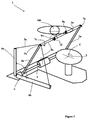
- a landing device 1 for drone 100 comprises a landing platform 2 and a pair of mats 3a and 3b parallel to each other.
- the first ends or lower ends of the mats 3a and 3b are integral with a hinge 4 for pivoting the mats 3 in situ, towards the platform 2.
- the lowering and lifting movement of the mats 3a and 3b will be obtained by the intermediate motor means not shown and conventionally known to those skilled in the art such as a cylinder or an electric motor.
- an electric motor may be provided at the level of the rectangular block corresponding to the hinge 4 in the figures.
- the second ends or upper ends of the mats 3a and 3b, as they are positioned at the figure 1 , are connected by a pair of strands 5a and 5b parallel along their length.
- the two strands 5a and 5b are integral with one another and form one and the same cable 5 passing from one mat 3a to the other mat 3b via pulleys 7a, 7b, 7c located at the ends of each mat.
- the free ends of the cable 5 are integral with the ends of two rods: a first rod 6a and a second rod 6b.
- the first strand 5a is thus connected to the first rod 6a the most oriented towards the vertical while the second strand 5b is connected to the end of the second rod 6b, the most oriented horizontal.
- the rods 6a and 6b form between them an angle ⁇ and they are fixed relative to the platform 2.
- the cable 5 travels between the mats 3a and 3b via pulleys 7a, 7b and 7c to allow the translation of the strands 5a and 5b of the cable 5 between the mats 3a and 3b.
- the first mat 3a comprises a first pulley 7a (called return pulley) which allows the return of the cable 5 from the second mat 3b to the same mat 3b after a passage at the end of the first mat 3a.
- the second mat 3b has a second pulley 7b and a third pulley 7c which are intended to serve as an angle of the strands 5a and 5b respectively from the rods 6a and 6b and passing through the end of the second mat 3b to the first mat 3a.
- the cable 5 has a first end attached to the first rod 6a, this cable then passes at the second pulley 7b secured to the second mat 3b, then it joins the first pulley 7a fixed to the first mat 3a. It then joins the third pulley 7c secured to the second mat 3b which returns the cable 5 to the end of the second rod 6b.
- the first strand 5a of the cable 5 carries a first puck 9a which is located near the first mat 3a when the mats 3 are vertical.
- the second strand 5b of the cable 5 carries a second puck 9b which is located in the vicinity of the second mat 3b when the mats 3 are vertical.
- Each puck 9a and 9b comprises a plate substantially perpendicular to its carrying strand (plate not visible in the figure).
- the drone 100 has full latitude to hang on any point of the cable 5 located between the two mats 3a and 3b.
- the hook 11 of the drone 100 will in fact be located between the pallets 9a and 9b.
- the pallets 9a and 9b will comprise a magnet intended to adhere with a magnetic hook 11 of the drone 100 in order to improve the attachment capabilities of the device 1.
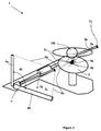
- the cable 5 When lowering the mats 3 as shown in FIG. figure 2 , the cable 5 is put in slight tension at the end of the first strand 5a which is connected to the first rod 6a due to the friction of the cable 5 in the pulleys 7a and 7b. In doing so, relative to the mats 3a and 3b, the cable 5 will translate between the mats 3a and 3b and the pallets 9a and 9b will move closer to one another.
- the hook 11 of the drone 100 located between the two pallets 9a and 9b will come into contact with one of the pallets 9a or 9b and be guided in translation by the pallet 5a or 5b along the cable 5 and be brought gradually to the middle the distance between mats 3a and 3b.
- the pallets grip the hook 11 on either side of it and the pallet 9a, 9b and hook 11 is precisely positioned on the center C of the platform 2.
- the center C of the platform as a point of the platform 2 which is located at the middle of the cable segment 5 touching the platform when it is in contact with the platform 2.
- the drone 100 is thus placed accurately on an area reduced to only surface necessary for its support on the ground which solves the problem of necessary space of the platform of the prior art. It is therefore possible to make a platform 2 of reduced dimensions.
- the invention according to this embodiment also makes it possible to improve the prior art without complicating the device by the addition of additional engines.
- the rods 6a and 6b in association with the pulleys 7a, 7b and 7c and the cable 5 form a displacement means 6.
- the rods 6a and 6b respectively comprise at their end a first point of attachment 88 and a second point of attachment 99 for fixing respectively the first and the second end of the cable 5.
- the points of attachment 88 and 99 are the foci of an ellipse 77 defined by the fact that each of the points of this ellipse 77 is such that the sum of the lengths of the strands 5a and 5b located between the points of attachment 88 and 99 and the end E of the second mat 3b is constant.
- the end E of the second mat 3b describes a circle 101 centered on the hinge 4.
- the cable 5 is not extensible, it is necessary, in order to avoid any blockage during the movement of the mat, to position the attachment points 88 and 99 with respect to the mat 3b and to the hinge 4 so that the circular path traveled by the end E of the mast 3b is as close as possible to the elliptical trajectory having focal points 88 and 99 and passing through the end E of the mast.
- the skilled person will therefore define the geometry of the assembly by sufficiently removing the foci (thus the attachment points 88 and 99) so that the stroke of the mat 3b is possible for all the desired amplitude between the vertical and the platform and also by locating the articulation 4 with respect to the foci so as to make the osculating circle 101 or a tangent circle of radius very close to that of the osculating circle pass through the end E of the mat 3b.
- an elastic means 80 on the cable 5 also allows a slight elongation of the cable which makes it possible to overcome the minimal differences between the circular path 101 of the end E of the mat 3b and the profile of the ellipse 77 imposed by the presence of the cable. If for a given device, the distance between the ellipse 77 and the osculating circle 101 is very low, it can be absorbed by the elasticity of the cable 5 or device 1. In addition the elastic means 80 also damps the movement of the drone 100 during its attachment.
- the second attachment point 99 is located substantially at the same height as the platform 2 or below it.
- the distance L separating the strands 5a and 5b from the center C of the platform 2 is equivalent to half the distance D between the pallets 9a and 9b.
- the first strand 5a carries the first puck 9a in the vicinity of the first mat 3a and the second strand 5b carries the second puck 9b in the vicinity of the second mat 3b.
- the distance D is therefore substantially equal to the distance between the ends of the mats 3a and 3b.
- the end of one of the mats 3a carries a moving means 6 which is constituted by an electric motor 6.
- the upper end of the other mast 3b has a pulley 7a.
- the motorization 6 drives a coil which allows the movement of the cable 5 and by association, the pallets 9a and 9b.
- the winding of the first strand 5a towards the motorization 12 involves the unwinding of the second strand 5b. Pucks 9a and 9b will then move closer. The movement of bringing palets 9a and 9b is controlled when the drone 100 is hooked. This command may be made by an observer having a control means (control means and observer not shown) or by detecting the voltage caused by the drone on the cable (voltage detector not shown). Note that in this embodiment the moving means 6 of the pallets 9a and 9b is independent of the lowering of mats 3a and 3b. Thus, the lowering of the masts 3a and 3b can be done simultaneously with the approach of the pallets 9a and 9b, or else once the pallets 9a and 9b have gripped the hook 11.
- each puck 9a and 9b comprises a displacement means 6 which comprises an independent motor 6a and 6b able to move each puck 9a and 9b towards each other on a single cable strand 5.
- the lowering of the mats 3a and 3b may be made in correlation with the approach of the pallets 9a and 9b, or once the pallets 9a and 9b have gripped the hook 11.
- the hook 11 and therefore the drone 100 will be positioned in the middle of the distance D between the mats 3a and 3b which exactly positions the drone 100 on the platform 2.
Landscapes
- Engineering & Computer Science (AREA)
- Aviation & Aerospace Engineering (AREA)
- Mechanical Engineering (AREA)
- Remote Sensing (AREA)
- Catching Or Destruction (AREA)
- Manipulator (AREA)
- Invalid Beds And Related Equipment (AREA)
Applications Claiming Priority (1)
| Application Number | Priority Date | Filing Date | Title |
|---|---|---|---|
| FR1500079A FR3031501B1 (fr) | 2015-01-14 | 2015-01-14 | Dispositif d'atterrissage pour drone |
Publications (2)
| Publication Number | Publication Date |
|---|---|
| EP3045392A1 true EP3045392A1 (de) | 2016-07-20 |
| EP3045392B1 EP3045392B1 (de) | 2017-11-15 |
Family
ID=53491565
Family Applications (1)
| Application Number | Title | Priority Date | Filing Date |
|---|---|---|---|
| EP16150820.5A Active EP3045392B1 (de) | 2015-01-14 | 2016-01-11 | Landevorrichtung für drohne |
Country Status (2)
| Country | Link |
|---|---|
| EP (1) | EP3045392B1 (de) |
| FR (1) | FR3031501B1 (de) |
Cited By (2)
| Publication number | Priority date | Publication date | Assignee | Title |
|---|---|---|---|---|
| CN110654559A (zh) * | 2017-10-13 | 2020-01-07 | 南京涵曦月自动化科技有限公司 | 一种旋翼无人机的起落控制装置的控制方法 |
| CN112829959A (zh) * | 2021-02-10 | 2021-05-25 | 成都两江前沿科技有限公司 | 一种固定翼无人机移动发射回收一体化平台 |
Families Citing this family (1)
| Publication number | Priority date | Publication date | Assignee | Title |
|---|---|---|---|---|
| CN211223917U (zh) * | 2018-07-30 | 2020-08-11 | 魏荣亮 | 用于垂直升降飞行器的着舰装置及舰船 |
Citations (4)
| Publication number | Priority date | Publication date | Assignee | Title |
|---|---|---|---|---|
| US20080156932A1 (en) * | 2006-08-24 | 2008-07-03 | Hood Technology Corporation | Method and apparatus for retrieving a hovering aircraft |
| US20090224097A1 (en) | 2006-07-31 | 2009-09-10 | Amnon Kariv | Unmanned aerial vehicle launching and landing system |
| US20090294584A1 (en) * | 2008-06-02 | 2009-12-03 | Gilbert Lovell | Stabilized UAV recovery system |
| WO2013171735A1 (en) * | 2012-05-16 | 2013-11-21 | Meir Yoffe | Point take-off and landing of unmanned flying objects |
-
2015
- 2015-01-14 FR FR1500079A patent/FR3031501B1/fr not_active Expired - Fee Related
-
2016
- 2016-01-11 EP EP16150820.5A patent/EP3045392B1/de active Active
Patent Citations (4)
| Publication number | Priority date | Publication date | Assignee | Title |
|---|---|---|---|---|
| US20090224097A1 (en) | 2006-07-31 | 2009-09-10 | Amnon Kariv | Unmanned aerial vehicle launching and landing system |
| US20080156932A1 (en) * | 2006-08-24 | 2008-07-03 | Hood Technology Corporation | Method and apparatus for retrieving a hovering aircraft |
| US20090294584A1 (en) * | 2008-06-02 | 2009-12-03 | Gilbert Lovell | Stabilized UAV recovery system |
| WO2013171735A1 (en) * | 2012-05-16 | 2013-11-21 | Meir Yoffe | Point take-off and landing of unmanned flying objects |
Cited By (3)
| Publication number | Priority date | Publication date | Assignee | Title |
|---|---|---|---|---|
| CN110654559A (zh) * | 2017-10-13 | 2020-01-07 | 南京涵曦月自动化科技有限公司 | 一种旋翼无人机的起落控制装置的控制方法 |
| CN110654559B (zh) * | 2017-10-13 | 2021-05-28 | 南京涵曦月自动化科技有限公司 | 一种旋翼无人机的起落控制装置的控制方法 |
| CN112829959A (zh) * | 2021-02-10 | 2021-05-25 | 成都两江前沿科技有限公司 | 一种固定翼无人机移动发射回收一体化平台 |
Also Published As
| Publication number | Publication date |
|---|---|
| EP3045392B1 (de) | 2017-11-15 |
| FR3031501A1 (fr) | 2016-07-15 |
| FR3031501B1 (fr) | 2016-12-30 |
Similar Documents
| Publication | Publication Date | Title |
|---|---|---|
| EP3045392B1 (de) | Landevorrichtung für drohne | |
| EP3456601B1 (de) | Fördersystem eines länglichen bauelements, förderfahrzeug, das mit einem solchen system ausgestattet ist | |
| CA1080190A (fr) | Methode et dispositif de rangement automatique d'un element allonge flexible dans un panier tournant d'axe vertical | |
| EP3536899B1 (de) | Bohrmaschine, die eine anschlussvorrichtung für eine messvorrichtung der vertikalität umfasst | |
| EP3493886B1 (de) | Bühnenbild-manövrierungsvorrichtung | |
| FR3097287A1 (fr) | Dispositif de verouillage d'un objet pendu a un cable | |
| EP2468621B1 (de) | Vorrichtung zur Zuwasserlassung und Bergung eines Unterwasser- oder Oberflächengeräts | |
| EP3783760B1 (de) | Vorrichtung und verfahren zum anbringen einer optischen vogelabwehr auf einer freileitung | |
| EP3070203B1 (de) | Be-, entlade- und aufsetzsystem einer schienenweiche auf ein bahngleis | |
| WO2020128316A1 (fr) | Systeme et procede d'arrimage ameliores d'un aerostat sur une structure receptrice | |
| EP4048621B1 (de) | Kran mit teleskopausleger und verfahren zur handhabung einer last mit einem solchen kran | |
| FR3017196A1 (fr) | Dispositif de protection contre les intemperies pour structure de captation solaire a concentration | |
| FR3021337A1 (fr) | Portique de coffrage et coffrage muni d'un tel portique, procede de decoffrage, procede de fabrication de portion de mur ou de batiment, portion de mur et batiment. | |
| FR2464218A1 (fr) | Dispositif de recuperation d'un cable de manutention d'une charge immergee | |
| FR2679544A1 (fr) | Appareilage autonome permettant d'extraire et deplacer des elements encastres dans le sol, tels que plaques d'egouts, grilles. | |
| FR3132183A1 (fr) | Dispositif et procédé de pose d’une balise sur un câble aérien par une interface mécanique | |
| FR2877656A1 (fr) | Systeme de plate-forme elevatrice | |
| EP3791845A1 (de) | Aufnahmehalterung zum motorisierten beladen und herausziehen eines wagens, der eine krankentrage umfasst, und entsprechender krankenwagen | |
| CH286392A (fr) | Dispositif racleur pour le nettoyage d'une grille d'installation hydraulique. | |
| EP1222893A2 (de) | Anordnung und Vorrichtung zum Bewegen eines schweren Teils | |
| EP0290344A1 (de) | Verfahren und Vorrichtung zum Kalandrieren von Glasverbundscheiben | |
| EP3266736B1 (de) | Vorrichtung zum blockieren einer aufzugskabine in einer schacht | |
| FR2547568A1 (fr) | Monte-materiaux a equipage mobile deplacable verticalement et horizontalement | |
| FR2746783A1 (fr) | Support equilibreur de charges | |
| FR2557551A1 (fr) | Pince automatique pour la manutention et le levage de charges |
Legal Events
| Date | Code | Title | Description |
|---|---|---|---|
| PUAI | Public reference made under article 153(3) epc to a published international application that has entered the european phase |
Free format text: ORIGINAL CODE: 0009012 |
|
| AK | Designated contracting states |
Kind code of ref document: A1 Designated state(s): AL AT BE BG CH CY CZ DE DK EE ES FI FR GB GR HR HU IE IS IT LI LT LU LV MC MK MT NL NO PL PT RO RS SE SI SK SM TR |
|
| AX | Request for extension of the european patent |
Extension state: BA ME |
|
| 17P | Request for examination filed |
Effective date: 20161223 |
|
| RBV | Designated contracting states (corrected) |
Designated state(s): AL AT BE BG CH CY CZ DE DK EE ES FI FR GB GR HR HU IE IS IT LI LT LU LV MC MK MT NL NO PL PT RO RS SE SI SK SM TR |
|
| GRAP | Despatch of communication of intention to grant a patent |
Free format text: ORIGINAL CODE: EPIDOSNIGR1 |
|
| RIC1 | Information provided on ipc code assigned before grant |
Ipc: B64F 1/02 20060101AFI20170517BHEP |
|
| INTG | Intention to grant announced |
Effective date: 20170609 |
|
| GRAS | Grant fee paid |
Free format text: ORIGINAL CODE: EPIDOSNIGR3 |
|
| GRAA | (expected) grant |
Free format text: ORIGINAL CODE: 0009210 |
|
| AK | Designated contracting states |
Kind code of ref document: B1 Designated state(s): AL AT BE BG CH CY CZ DE DK EE ES FI FR GB GR HR HU IE IS IT LI LT LU LV MC MK MT NL NO PL PT RO RS SE SI SK SM TR |
|
| REG | Reference to a national code |
Ref country code: CH Ref legal event code: EP Ref country code: GB Ref legal event code: FG4D Free format text: NOT ENGLISH Ref country code: AT Ref legal event code: REF Ref document number: 946004 Country of ref document: AT Kind code of ref document: T Effective date: 20171115 |
|
| REG | Reference to a national code |
Ref country code: IE Ref legal event code: FG4D Free format text: LANGUAGE OF EP DOCUMENT: FRENCH |
|
| REG | Reference to a national code |
Ref country code: FR Ref legal event code: PLFP Year of fee payment: 3 |
|
| REG | Reference to a national code |
Ref country code: DE Ref legal event code: R096 Ref document number: 602016000762 Country of ref document: DE |
|
| REG | Reference to a national code |
Ref country code: NL Ref legal event code: FP |
|
| REG | Reference to a national code |
Ref country code: LT Ref legal event code: MG4D |
|
| REG | Reference to a national code |
Ref country code: AT Ref legal event code: MK05 Ref document number: 946004 Country of ref document: AT Kind code of ref document: T Effective date: 20171115 |
|
| PG25 | Lapsed in a contracting state [announced via postgrant information from national office to epo] |
Ref country code: NO Free format text: LAPSE BECAUSE OF FAILURE TO SUBMIT A TRANSLATION OF THE DESCRIPTION OR TO PAY THE FEE WITHIN THE PRESCRIBED TIME-LIMIT Effective date: 20180215 Ref country code: SE Free format text: LAPSE BECAUSE OF FAILURE TO SUBMIT A TRANSLATION OF THE DESCRIPTION OR TO PAY THE FEE WITHIN THE PRESCRIBED TIME-LIMIT Effective date: 20171115 Ref country code: ES Free format text: LAPSE BECAUSE OF FAILURE TO SUBMIT A TRANSLATION OF THE DESCRIPTION OR TO PAY THE FEE WITHIN THE PRESCRIBED TIME-LIMIT Effective date: 20171115 Ref country code: LT Free format text: LAPSE BECAUSE OF FAILURE TO SUBMIT A TRANSLATION OF THE DESCRIPTION OR TO PAY THE FEE WITHIN THE PRESCRIBED TIME-LIMIT Effective date: 20171115 Ref country code: FI Free format text: LAPSE BECAUSE OF FAILURE TO SUBMIT A TRANSLATION OF THE DESCRIPTION OR TO PAY THE FEE WITHIN THE PRESCRIBED TIME-LIMIT Effective date: 20171115 |
|
| PG25 | Lapsed in a contracting state [announced via postgrant information from national office to epo] |
Ref country code: AT Free format text: LAPSE BECAUSE OF FAILURE TO SUBMIT A TRANSLATION OF THE DESCRIPTION OR TO PAY THE FEE WITHIN THE PRESCRIBED TIME-LIMIT Effective date: 20171115 Ref country code: RS Free format text: LAPSE BECAUSE OF FAILURE TO SUBMIT A TRANSLATION OF THE DESCRIPTION OR TO PAY THE FEE WITHIN THE PRESCRIBED TIME-LIMIT Effective date: 20171115 Ref country code: LV Free format text: LAPSE BECAUSE OF FAILURE TO SUBMIT A TRANSLATION OF THE DESCRIPTION OR TO PAY THE FEE WITHIN THE PRESCRIBED TIME-LIMIT Effective date: 20171115 Ref country code: HR Free format text: LAPSE BECAUSE OF FAILURE TO SUBMIT A TRANSLATION OF THE DESCRIPTION OR TO PAY THE FEE WITHIN THE PRESCRIBED TIME-LIMIT Effective date: 20171115 Ref country code: BG Free format text: LAPSE BECAUSE OF FAILURE TO SUBMIT A TRANSLATION OF THE DESCRIPTION OR TO PAY THE FEE WITHIN THE PRESCRIBED TIME-LIMIT Effective date: 20180215 Ref country code: GR Free format text: LAPSE BECAUSE OF FAILURE TO SUBMIT A TRANSLATION OF THE DESCRIPTION OR TO PAY THE FEE WITHIN THE PRESCRIBED TIME-LIMIT Effective date: 20180216 |
|
| PG25 | Lapsed in a contracting state [announced via postgrant information from national office to epo] |
Ref country code: CZ Free format text: LAPSE BECAUSE OF FAILURE TO SUBMIT A TRANSLATION OF THE DESCRIPTION OR TO PAY THE FEE WITHIN THE PRESCRIBED TIME-LIMIT Effective date: 20171115 Ref country code: EE Free format text: LAPSE BECAUSE OF FAILURE TO SUBMIT A TRANSLATION OF THE DESCRIPTION OR TO PAY THE FEE WITHIN THE PRESCRIBED TIME-LIMIT Effective date: 20171115 Ref country code: CY Free format text: LAPSE BECAUSE OF FAILURE TO SUBMIT A TRANSLATION OF THE DESCRIPTION OR TO PAY THE FEE WITHIN THE PRESCRIBED TIME-LIMIT Effective date: 20171115 Ref country code: DK Free format text: LAPSE BECAUSE OF FAILURE TO SUBMIT A TRANSLATION OF THE DESCRIPTION OR TO PAY THE FEE WITHIN THE PRESCRIBED TIME-LIMIT Effective date: 20171115 Ref country code: SK Free format text: LAPSE BECAUSE OF FAILURE TO SUBMIT A TRANSLATION OF THE DESCRIPTION OR TO PAY THE FEE WITHIN THE PRESCRIBED TIME-LIMIT Effective date: 20171115 |
|
| REG | Reference to a national code |
Ref country code: DE Ref legal event code: R097 Ref document number: 602016000762 Country of ref document: DE |
|
| PG25 | Lapsed in a contracting state [announced via postgrant information from national office to epo] |
Ref country code: RO Free format text: LAPSE BECAUSE OF FAILURE TO SUBMIT A TRANSLATION OF THE DESCRIPTION OR TO PAY THE FEE WITHIN THE PRESCRIBED TIME-LIMIT Effective date: 20171115 Ref country code: SM Free format text: LAPSE BECAUSE OF FAILURE TO SUBMIT A TRANSLATION OF THE DESCRIPTION OR TO PAY THE FEE WITHIN THE PRESCRIBED TIME-LIMIT Effective date: 20171115 Ref country code: PL Free format text: LAPSE BECAUSE OF FAILURE TO SUBMIT A TRANSLATION OF THE DESCRIPTION OR TO PAY THE FEE WITHIN THE PRESCRIBED TIME-LIMIT Effective date: 20171115 |
|
| PLBE | No opposition filed within time limit |
Free format text: ORIGINAL CODE: 0009261 |
|
| STAA | Information on the status of an ep patent application or granted ep patent |
Free format text: STATUS: NO OPPOSITION FILED WITHIN TIME LIMIT |
|
| PG25 | Lapsed in a contracting state [announced via postgrant information from national office to epo] |
Ref country code: MT Free format text: LAPSE BECAUSE OF FAILURE TO SUBMIT A TRANSLATION OF THE DESCRIPTION OR TO PAY THE FEE WITHIN THE PRESCRIBED TIME-LIMIT Effective date: 20171115 |
|
| 26N | No opposition filed |
Effective date: 20180817 |
|
| PG25 | Lapsed in a contracting state [announced via postgrant information from national office to epo] |
Ref country code: LU Free format text: LAPSE BECAUSE OF NON-PAYMENT OF DUE FEES Effective date: 20180111 |
|
| REG | Reference to a national code |
Ref country code: IE Ref legal event code: MM4A |
|
| PG25 | Lapsed in a contracting state [announced via postgrant information from national office to epo] |
Ref country code: SI Free format text: LAPSE BECAUSE OF FAILURE TO SUBMIT A TRANSLATION OF THE DESCRIPTION OR TO PAY THE FEE WITHIN THE PRESCRIBED TIME-LIMIT Effective date: 20171115 |
|
| PG25 | Lapsed in a contracting state [announced via postgrant information from national office to epo] |
Ref country code: IE Free format text: LAPSE BECAUSE OF NON-PAYMENT OF DUE FEES Effective date: 20180111 |
|
| PG25 | Lapsed in a contracting state [announced via postgrant information from national office to epo] |
Ref country code: MC Free format text: LAPSE BECAUSE OF FAILURE TO SUBMIT A TRANSLATION OF THE DESCRIPTION OR TO PAY THE FEE WITHIN THE PRESCRIBED TIME-LIMIT Effective date: 20171115 |
|
| REG | Reference to a national code |
Ref country code: CH Ref legal event code: PL |
|
| PG25 | Lapsed in a contracting state [announced via postgrant information from national office to epo] |
Ref country code: CH Free format text: LAPSE BECAUSE OF NON-PAYMENT OF DUE FEES Effective date: 20190131 Ref country code: LI Free format text: LAPSE BECAUSE OF NON-PAYMENT OF DUE FEES Effective date: 20190131 |
|
| PG25 | Lapsed in a contracting state [announced via postgrant information from national office to epo] |
Ref country code: TR Free format text: LAPSE BECAUSE OF FAILURE TO SUBMIT A TRANSLATION OF THE DESCRIPTION OR TO PAY THE FEE WITHIN THE PRESCRIBED TIME-LIMIT Effective date: 20171115 |
|
| PG25 | Lapsed in a contracting state [announced via postgrant information from national office to epo] |
Ref country code: PT Free format text: LAPSE BECAUSE OF FAILURE TO SUBMIT A TRANSLATION OF THE DESCRIPTION OR TO PAY THE FEE WITHIN THE PRESCRIBED TIME-LIMIT Effective date: 20171115 |
|
| PG25 | Lapsed in a contracting state [announced via postgrant information from national office to epo] |
Ref country code: HU Free format text: LAPSE BECAUSE OF FAILURE TO SUBMIT A TRANSLATION OF THE DESCRIPTION OR TO PAY THE FEE WITHIN THE PRESCRIBED TIME-LIMIT; INVALID AB INITIO Effective date: 20160111 Ref country code: MK Free format text: LAPSE BECAUSE OF NON-PAYMENT OF DUE FEES Effective date: 20171115 |
|
| PG25 | Lapsed in a contracting state [announced via postgrant information from national office to epo] |
Ref country code: AL Free format text: LAPSE BECAUSE OF FAILURE TO SUBMIT A TRANSLATION OF THE DESCRIPTION OR TO PAY THE FEE WITHIN THE PRESCRIBED TIME-LIMIT Effective date: 20171115 Ref country code: IS Free format text: LAPSE BECAUSE OF FAILURE TO SUBMIT A TRANSLATION OF THE DESCRIPTION OR TO PAY THE FEE WITHIN THE PRESCRIBED TIME-LIMIT Effective date: 20180315 |
|
| PGFP | Annual fee paid to national office [announced via postgrant information from national office to epo] |
Ref country code: GB Payment date: 20251219 Year of fee payment: 11 |
|
| PGFP | Annual fee paid to national office [announced via postgrant information from national office to epo] |
Ref country code: NL Payment date: 20251217 Year of fee payment: 11 Ref country code: FR Payment date: 20251217 Year of fee payment: 11 |
|
| PGFP | Annual fee paid to national office [announced via postgrant information from national office to epo] |
Ref country code: BE Payment date: 20251217 Year of fee payment: 11 |
|
| PGFP | Annual fee paid to national office [announced via postgrant information from national office to epo] |
Ref country code: DE Payment date: 20251217 Year of fee payment: 11 |
|
| PGFP | Annual fee paid to national office [announced via postgrant information from national office to epo] |
Ref country code: IT Payment date: 20260107 Year of fee payment: 11 |