EP3045242A1 - Cutting insert - Google Patents
Cutting insert Download PDFInfo
- Publication number
- EP3045242A1 EP3045242A1 EP14841850.2A EP14841850A EP3045242A1 EP 3045242 A1 EP3045242 A1 EP 3045242A1 EP 14841850 A EP14841850 A EP 14841850A EP 3045242 A1 EP3045242 A1 EP 3045242A1
- Authority
- EP
- European Patent Office
- Prior art keywords
- cutting
- width direction
- chips
- shoulder portions
- cutting edge
- Prior art date
- Legal status (The legal status is an assumption and is not a legal conclusion. Google has not performed a legal analysis and makes no representation as to the accuracy of the status listed.)
- Granted
Links
Images



Classifications
-
- B—PERFORMING OPERATIONS; TRANSPORTING
- B23—MACHINE TOOLS; METAL-WORKING NOT OTHERWISE PROVIDED FOR
- B23B—TURNING; BORING
- B23B27/00—Tools for turning or boring machines; Tools of a similar kind in general; Accessories therefor
- B23B27/04—Cutting-off tools
- B23B27/045—Cutting-off tools with chip-breaking arrangements
-
- B—PERFORMING OPERATIONS; TRANSPORTING
- B23—MACHINE TOOLS; METAL-WORKING NOT OTHERWISE PROVIDED FOR
- B23B—TURNING; BORING
- B23B2200/00—Details of cutting inserts
- B23B2200/08—Rake or top surfaces
- B23B2200/086—Rake or top surfaces with one or more grooves
- B23B2200/087—Rake or top surfaces with one or more grooves for chip breaking
-
- B—PERFORMING OPERATIONS; TRANSPORTING
- B23—MACHINE TOOLS; METAL-WORKING NOT OTHERWISE PROVIDED FOR
- B23B—TURNING; BORING
- B23B2200/00—Details of cutting inserts
- B23B2200/28—Angles
- B23B2200/286—Positive cutting angles
-
- B—PERFORMING OPERATIONS; TRANSPORTING
- B23—MACHINE TOOLS; METAL-WORKING NOT OTHERWISE PROVIDED FOR
- B23B—TURNING; BORING
- B23B2220/00—Details of turning, boring or drilling processes
- B23B2220/12—Grooving
-
- B—PERFORMING OPERATIONS; TRANSPORTING
- B23—MACHINE TOOLS; METAL-WORKING NOT OTHERWISE PROVIDED FOR
- B23B—TURNING; BORING
- B23B27/00—Tools for turning or boring machines; Tools of a similar kind in general; Accessories therefor
- B23B27/04—Cutting-off tools
-
- B—PERFORMING OPERATIONS; TRANSPORTING
- B23—MACHINE TOOLS; METAL-WORKING NOT OTHERWISE PROVIDED FOR
- B23B—TURNING; BORING
- B23B27/00—Tools for turning or boring machines; Tools of a similar kind in general; Accessories therefor
- B23B27/14—Cutting tools of which the bits or tips or cutting inserts are of special material
-
- B—PERFORMING OPERATIONS; TRANSPORTING
- B23—MACHINE TOOLS; METAL-WORKING NOT OTHERWISE PROVIDED FOR
- B23B—TURNING; BORING
- B23B29/00—Holders for non-rotary cutting tools; Boring bars or boring heads; Accessories for tool holders
- B23B29/04—Tool holders for a single cutting tool
- B23B29/043—Tool holders for a single cutting tool with cutting-off, grooving or profile cutting tools, i.e. blade- or disc-like main cutting parts
Definitions
- This invention relates to a cutting insert for turning, such as cutting off or grooving.
- PTL 1 below describes a known structure of a cutting tool for turning, such as cutting off or grooving.
- a recess having a curved groove surface is formed in a rake face in a central region in a width direction, and the recess serves as a breaker for curling chips.
- the recess has a width that gradually decreases with increasing distance from the cutting edge, so that the chips receive not only a curling force but also a bending force in the width direction.
- chips are deformed by being pushed into the recess in the central region of the rake face in the width direction and bent in the width direction.
- the chips bent in the width direction also receive a curling force.
- the chips are deformed into a complex shape and easily break.
- the chips are appropriately processed.
- the chips evacuate along the groove surface of the recess while increasing the amount by which the chips are bent in the width direction, the following problems occur. That is, when conditions are such that the chips are thin and hard to curl as in the case where a stainless steel is processed at a low feed rate, since the breaker operates (functions) over a region that extends to a position distant from the leading cutting edge, there is a problem that the chips are excessively restrained and the cutting force increases.
- An object of the present invention is to provide a cutting insert for cutting off or grooving with which the cutting force can be reduced while a high chip-processing performance is maintained.
- a cutting insert for cutting off or grooving has the following structure.
- the cutting insert includes a leading cutting edge having a rake angle in the range of 20° to 35° in a central region in a width direction; and a rake face having a breaker groove formed in the central region in the width direction and land portions formed in both end regions in the width direction.
- the land portions have a rake angle smaller than the rake angle in the central region in the width direction.
- the breaker groove includes opposing side faces separated from each other by a distance that decreases with increasing distance from the leading cutting edge and four shoulder portions of the same height that are formed on the opposing side faces at positions above the land portions, two of the shoulder portions being closer to the leading cutting edge and to outer sides in the width direction than the other two shoulder portions are.
- the cutting force can be reduced while a high chip-processing performance is maintained.
- a cutting insert 1 illustrated in Figs. 1 to 4 includes a leading cutting edge 2, a rake face 3 that is connected to the leading cutting edge, and a chip breaker.
- Reference numeral 4 in Figs. 2 , 3, and 4 denotes a front flank face
- reference numeral 5 in Figs. 2 and 4 denotes side flank faces.
- the front flank face 4 and the side flank faces 5 have clearance angles in the range of about 5° to 16°.
- Reference numeral 6 in Figs. 1 and 4 denotes a clamping V-groove formed in a top face 7.
- a clamp portion (not shown) of a cutting-tool holder is engaged with the top face having the V-groove 6 and a bottom face (which also has a V-groove or V-shaped projection) of the cutting insert, so that the cutting insert 1 is fixed to the cutting-tool holder.
- the manner in which the cutting insert 1 is fixed to the cutting-tool holder is not limited to this.
- the leading cutting edge 2 is a cutting edge having a leading cutting edge angle of 0°.
- the leading cutting edge 2 has a positive rake angle ⁇ in a region excluding both end regions (central region in the width direction), as illustrated in Fig. 3 .
- the rake angle ⁇ is in the range 20° to 35°. Such a large rake angle is particularly effective in appropriately processing chips when a tough metal, such as stainless steel, is processed at a low feed rate.
- the rake angle is smaller in both end regions of the rake face 3 (regions along the side flank faces) than in the central region, and the end regions serve as land portions (in the illustrated cutting insert, flat lands having a rake angle of 0°) 8 in which importance is given to the strength.
- Inclined faces 9 that are curved upward toward the top face 7 are connected to back portions (side opposite the side at which the leading cutting edge is provided is defined as the back side) of the land portions 8.
- the height of a region of the rake face 3 having a positive rake angle ⁇ gradually decreases with increasing distance from the leading cutting edge 2, so that a breaker groove 10 is formed between the land portions 8 and 8 at both ends, that is, in a central region of the rake face 3 in the width direction.
- the breaker groove 10 includes opposing side faces 10a and 10a that are separated from each other by a distance that decreases with increasing distance from the leading cutting edge 2.
- the opposing side faces 10a and 10a obliquely extend upward in opposite directions from the bottom of the breaker groove 10 to positions where they intersect the land portions 8, the inclined faces 9, and the top face 7.
- an inclination angle ⁇ (see Fig. 1 ) of the opposing side faces 10a with respect to the leading cutting edge 2 is set to 10° in plan view of the insert.
- the inclination angle ⁇ is preferably in the range 5° to 13°.
- the breaker groove 10 of the chip breaker includes four shoulder portions 10b, 10b, 10c, and 10c that are at the same height and that project toward each other on the opposing side faces 10a and 10a at positions above the land portion 8.
- two shoulder portions 10b and 10b that are closer to the leading cutting edge 2 are formed at the positions where the land portions 8, the inclined faces 9, and the top face 7 intersect, and the distance L1 therebetween illustrated in Fig. 5 is set to around 50% of an edge width W (also illustrated in Fig. 5 ).
- the remaining two shoulder portions 10c and 10c are formed in a region behind the inclined faces 9 at the positions where inclined faces that extend upward from the bottom of relief portions 10d provided on the breaker groove 10, groove side surfaces in a region where the width of the breaker groove 10 is reduced, and the top face 7 intersect, and the distance L2 therebetween (see Fig. 5 ) is set to around 20% of the edge width W.
- the relief portions 10d are provided to prevent the chips from coming into contact with the groove surface at the locations thereof.
- the distance L1 between the shoulder portions 10b and 10b illustrated in Fig. 5 varies depending on the width w of the land portions 8 that is also illustrated in Fig. 5 , the inclination angle ⁇ of the opposing side faces 10a with respect to the leading cutting edge 2 in plan view of the insert illustrated in Fig. 1 , and the distance from the leading cutting edge 2 to the shoulder portions 10b.
- the distance L1 between the shoulder portions 10b and 10b is set to around 50% of the edge width W.
- This value is naturally determined when the dimensions of the cutting insert are set to common dimensions of a cutting insert for cutting off or grooving, the width of the land portions 8 is set to 10% of the edge width W as an appropriate value for ensuring sufficient strength in both end regions of the leading cutting edge 2 even when the rake angle is set to a large value to reduce the resistance, and the inclination angle ⁇ of the above-described opposing side faces 10a is set to about 10°.
- the distance L1 may be about 5% above or below the above-described set value. Therefore, the value is described as being "around 50%".
- the distance L2 between the shoulder portions 10c is preferably smaller than the distance L1 between the shoulder portions 10b by about 30% of the edge width. Therefore, the distance L2 is set to around 20% of the edge width W.
- This value allows the chips generated when a stainless steel is cut at a low feed rate, such as 0.05 mm/rev, to be sufficiently curled so that the evacuation performance can be improved. This value may also be increased or reduced by about 5%. When the value is further reduced, it is expected that the chips will be excessively restrained and the cutting force will be increased.
- chips generated during cutting off or grooving are guided into the breaker groove 10 and squeezed so that the chips are bent into a concave shape.
- the chip further moves toward the back of the breaker groove 10 and comes into contact with the shoulder portions 10c. Therefore, as illustrated in Fig. 8 , the chip C is further raised, and the curling force and the bending force in the width direction are increased so that, for example, thin and tough chips generated when a stainless steel is processed at a low feed rate can be appropriately curled.
- the chip does not come into contact in a region farther from the leading cutting edge than the shoulder portions are, and is not excessively restrained by the chip breaker.
- thick chips are deformed into a complex shape and break into small pieces.
- a sample of a cutting insert having the illustrated shape was manufactured.
- the dimensional specification of the sample was as follows. That is, referring to Fig. 5 , the edge width W was 3.0 mm, the width w of the lands (flat lands) 8 at both ends of the rake face was 0.3 mm, and the distance D1 from the leading cutting edge 2 to the shoulder portions 10b was 2.10 mm (about 70% of the edge width W).
- the rake angle 0 of the leading cutting edge 2 in a region excluding both end regions illustrated in Fig. 6 was 30°
- the rake angle in the regions where the lands 8 were formed was 0°
- the inclination angle ⁇ of the opposing side faces with respect to the leading cutting edge in plan view of the insert was 10°.
- Figures 10 and 14 illustrate the outlines of the commercially available cutting inserts.
- a commercially available cutting insert B has a chip breaker having substantially the same shape as that of a commercially available cutting insert A illustrated in Fig. 10 .
- Figure 11 illustrates the shape of a chip breaker of a commercially available cutting insert C
- Fig. 12 illustrates the shape of a chip breaker of a commercially available cutting insert D
- Fig. 13 illustrates the shape of a chip breaker of a commercially available cutting insert E
- Fig. 14 illustrates the shape of a chip breaker of a commercially available cutting insert F.
- the above-mentioned commercially available cutting inserts A to F are not provided with the four shoulder portions.
- Table 1 shows the results of the evaluation examination (principal force and thrust force of each cutting insert).
- the principal force and thrust force were measured by using a tool dynamometer.
- Figures 9A to 9C show chips generated by the sample.
- chips generated by the commercially available cutting insert D some chips that did not break and had a curl diameter greater than that of the chips formed by the sample were generated in the early stage of the process, and after that the chips broke into small pieces. However, the pieces into which the chips broke were spring-shaped and larger than those generated by the sample.
- Table 3 shows the results of the evaluation examination (principal force and thrust force of each cutting insert).
- the principal force and thrust force were measured by using a tool dynamometer.
- the conditions of the evaluation examination were as follows.
Landscapes
- Engineering & Computer Science (AREA)
- Mechanical Engineering (AREA)
- Cutting Tools, Boring Holders, And Turrets (AREA)
- Milling Processes (AREA)
Abstract
Description
- This invention relates to a cutting insert for turning, such as cutting off or grooving.
- PTL 1 below describes a known structure of a cutting tool for turning, such as cutting off or grooving.
- In the structure described in PTL I, a recess having a curved groove surface is formed in a rake face in a central region in a width direction, and the recess serves as a breaker for curling chips. The recess has a width that gradually decreases with increasing distance from the cutting edge, so that the chips receive not only a curling force but also a bending force in the width direction.
- PTL 1: Japanese Unexamined Patent Application Publication No.
2002-254216 - With the structure disclosed in PTL 1, for example, chips are deformed by being pushed into the recess in the central region of the rake face in the width direction and bent in the width direction. The chips bent in the width direction also receive a curling force.
- As a result, the chips are deformed into a complex shape and easily break. Thus, the chips are appropriately processed. However, since the chips evacuate along the groove surface of the recess while increasing the amount by which the chips are bent in the width direction, the following problems occur. That is, when conditions are such that the chips are thin and hard to curl as in the case where a stainless steel is processed at a low feed rate, since the breaker operates (functions) over a region that extends to a position distant from the leading cutting edge, there is a problem that the chips are excessively restrained and the cutting force increases.
- An object of the present invention is to provide a cutting insert for cutting off or grooving with which the cutting force can be reduced while a high chip-processing performance is maintained.
- To achieve the above-described object, in this invention, a cutting insert for cutting off or grooving has the following structure.
- That is, the cutting insert includes a leading cutting edge having a rake angle in the range of 20° to 35° in a central region in a width direction; and a rake face having a breaker groove formed in the central region in the width direction and land portions formed in both end regions in the width direction. The land portions have a rake angle smaller than the rake angle in the central region in the width direction. The breaker groove includes opposing side faces separated from each other by a distance that decreases with increasing distance from the leading cutting edge and four shoulder portions of the same height that are formed on the opposing side faces at positions above the land portions, two of the shoulder portions being closer to the leading cutting edge and to outer sides in the width direction than the other two shoulder portions are.
- With the cutting insert according to this invention having the above-described structure, the cutting force can be reduced while a high chip-processing performance is maintained.
-
- [
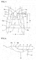
Fig. 1] Figure 1 is a plan view of a main part of an example of a cutting insert according to this invention. - [
Fig. 2] Figure 2 is a side view of the main part of the cutting insert illustrated inFig. 1 . - [
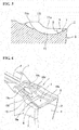
Fig. 3] Figure 3 is a sectional view taken along line III-III in Fig. I - [
Fig. 4] Figure 4 is a perspective view of the main part of the cutting insert illustrated inFig. 1 . - [
Fig. 5] Figure 5 is a plan view illustrating a dimensional specification of a sample of the cutting insert. - [
Fig. 6] Figure 6 is a side view illustrating a dimensional specification of the sample of the cutting insert. - [
Fig. 7] Figure 7 is a sectional view illustrating the state in which a chip is in contact with two shoulder portions of a chip breaker at a leading-cutting-edge side. - [
Fig. 8] Figure 8 is a sectional view illustrating the state in which a chip is in contact with the other two shoulder portions of the chip breaker. - [
Fig. 9A] Figure 9A illustrates chips formed by the sample in an evaluation examination when feed f = 0.05 mm/rev. - [
Fig. 9B] Figure 9B illustrates chips formed by the sample in the evaluation examination when feed f = 0.10 mm/rev. - [
Fig. 9C] Figure 9C illustrates chips formed by the sample in the evaluation examination when feed f = 0.15 mm/rev. - [
Fig. 10] Figure 10 is a perspective view illustrating the outline of chip breakers of commercially available cutting inserts A and B used in the evaluation examination. - [
Fig. 11] Figure 11 is a perspective view illustrating the outline of a chip breaker of a commercially available cutting insert C used in the evaluation examination. - [
Fig. 12] Figure 12 is a perspective view illustrating the outline of a chip breaker of a commercially available cutting insert D used in the evaluation examination. - [
Fig. 13] Figure 13 is a perspective view illustrating the outline of a chip breaker of a commercially available cutting insert E used in the evaluation examination. - [
Fig. 14] Figure 14 is a perspective view illustrating the outline of a chip breaker of a commercially available cutting insert F used in the evaluation examination. Description of Embodiments - A cutting insert according to an embodiment of this invention will now be described with reference to
Figs. 1 to 8 . - A cutting insert 1 illustrated in
Figs. 1 to 4 includes a leadingcutting edge 2, arake face 3 that is connected to the leading cutting edge, and a chip breaker. -
Reference numeral 4 inFigs. 2 ,3, and 4 denotes a front flank face, andreference numeral 5 inFigs. 2 and4 denotes side flank faces. Thefront flank face 4 and the side flank faces 5 have clearance angles in the range of about 5° to 16°. -
Reference numeral 6 inFigs. 1 and4 denotes a clamping V-groove formed in atop face 7. A clamp portion (not shown) of a cutting-tool holder is engaged with the top face having the V-groove 6 and a bottom face (which also has a V-groove or V-shaped projection) of the cutting insert, so that the cutting insert 1 is fixed to the cutting-tool holder. The manner in which the cutting insert 1 is fixed to the cutting-tool holder is not limited to this. - The leading
cutting edge 2 is a cutting edge having a leading cutting edge angle of 0°. The leadingcutting edge 2 has a positive rake angle θ in a region excluding both end regions (central region in the width direction), as illustrated inFig. 3 . The rake angle θ is in the range 20° to 35°. Such a large rake angle is particularly effective in appropriately processing chips when a tough metal, such as stainless steel, is processed at a low feed rate. - The rake angle is smaller in both end regions of the rake face 3 (regions along the side flank faces) than in the central region, and the end regions serve as land portions (in the illustrated cutting insert, flat lands having a rake angle of 0°) 8 in which importance is given to the strength.
- Inclined
faces 9 that are curved upward toward thetop face 7 are connected to back portions (side opposite the side at which the leading cutting edge is provided is defined as the back side) of theland portions 8. - The height of a region of the
rake face 3 having a positive rake angle θ gradually decreases with increasing distance from the leadingcutting edge 2, so that abreaker groove 10 is formed between theland portions rake face 3 in the width direction. - The
breaker groove 10 includes opposing side faces 10a and 10a that are separated from each other by a distance that decreases with increasing distance from the leadingcutting edge 2. - The opposing side faces 10a and 10a obliquely extend upward in opposite directions from the bottom of the
breaker groove 10 to positions where they intersect theland portions 8, theinclined faces 9, and thetop face 7. - In the illustrated cutting insert 1, an inclination angle α (see
Fig. 1 ) of the opposing side faces 10a with respect to the leadingcutting edge 2 is set to 10° in plan view of the insert. - When the inclination angle α is too small, chips cannot be sufficiently squeezed and bent in the width direction. When the inclination angle is too large, the evacuation resistance of the chips is increased and the cutting force cannot be effectively reduced. To balance these two functions, the inclination angle α is preferably in the
range 5° to 13°. - The
breaker groove 10 of the chip breaker includes fourshoulder portions land portion 8. - Among the four shoulder portions, two
shoulder portions cutting edge 2 are formed at the positions where theland portions 8, the inclined faces 9, and thetop face 7 intersect, and the distance L1 therebetween illustrated inFig. 5 is set to around 50% of an edge width W (also illustrated inFig. 5 ). - The remaining two
shoulder portions relief portions 10d provided on thebreaker groove 10, groove side surfaces in a region where the width of thebreaker groove 10 is reduced, and thetop face 7 intersect, and the distance L2 therebetween (seeFig. 5 ) is set to around 20% of the edge width W. - The
relief portions 10d are provided to prevent the chips from coming into contact with the groove surface at the locations thereof. - The distance L1 between the
shoulder portions Fig. 5 varies depending on the width w of theland portions 8 that is also illustrated inFig. 5 , the inclination angle α of the opposing side faces 10a with respect to the leadingcutting edge 2 in plan view of the insert illustrated inFig. 1 , and the distance from the leadingcutting edge 2 to theshoulder portions 10b. - In the illustrated cutting insert, the distance L1 between the
shoulder portions land portions 8 is set to 10% of the edge width W as an appropriate value for ensuring sufficient strength in both end regions of the leadingcutting edge 2 even when the rake angle is set to a large value to reduce the resistance, and the inclination angle α of the above-described opposing side faces 10a is set to about 10°. - Depending on the design conductions of the cutting insert, the distance L1 may be about 5% above or below the above-described set value. Therefore, the value is described as being "around 50%".
- The distance L2 between the
shoulder portions 10c is preferably smaller than the distance L1 between theshoulder portions 10b by about 30% of the edge width. Therefore, the distance L2 is set to around 20% of the edge width W. - This value allows the chips generated when a stainless steel is cut at a low feed rate, such as 0.05 mm/rev, to be sufficiently curled so that the evacuation performance can be improved. This value may also be increased or reduced by about 5%. When the value is further reduced, it is expected that the chips will be excessively restrained and the cutting force will be increased.
- With the turning insert 1 having the above-described structure, chips generated during cutting off or grooving are guided into the
breaker groove 10 and squeezed so that the chips are bent into a concave shape. - Since the distance between the opposing side faces 10a and 10a of the breaker groove gradually decreases with increasing distance from the leading
cutting edge 2, the degree to which the chips are squeezed (bent) increases toward the terminal end (back end) of thebreaker groove 10. However, since the chips come into contact with theshoulder portions 10b and are lifted upward during evacuation, as illustrated inFig. 7 , the chip C is raised from the groove surface of thebreaker groove 10. - Then, the chip further moves toward the back of the
breaker groove 10 and comes into contact with theshoulder portions 10c. Therefore, as illustrated inFig. 8 , the chip C is further raised, and the curling force and the bending force in the width direction are increased so that, for example, thin and tough chips generated when a stainless steel is processed at a low feed rate can be appropriately curled. Thus, the chip does not come into contact in a region farther from the leading cutting edge than the shoulder portions are, and is not excessively restrained by the chip breaker. In addition, thick chips are deformed into a complex shape and break into small pieces. - Since the chips come into point contact with the
shoulder portions - A sample of a cutting insert having the illustrated shape was manufactured. The dimensional specification of the sample was as follows. That is, referring to
Fig. 5 , the edge width W was 3.0 mm, the width w of the lands (flat lands) 8 at both ends of the rake face was 0.3 mm, and the distance D1 from the leadingcutting edge 2 to theshoulder portions 10b was 2.10 mm (about 70% of the edge width W). - The distance D2 from the leading
cutting edge 2 to theback shoulder portions 10c was 2.70 mm (about 90% of the edge width W, D3 = 0.60 mm), the distance L1 between theshoulder portions shoulder portions shoulder portions cutting edge 2 illustrated inFig. 6 was 0.30 mm. - The rake angle 0 of the leading
cutting edge 2 in a region excluding both end regions illustrated inFig. 6 was 30°, the rake angle in the regions where thelands 8 were formed was 0°, and the inclination angle α of the opposing side faces with respect to the leading cutting edge in plan view of the insert was 10°. - This sample and six types of commercially available cutting inserts for cutting off or grooving manufactured by other companies were used under the following conditions, and were compared in terms of cutting force and generated chips.
-
Figures 10 and14 illustrate the outlines of the commercially available cutting inserts. A commercially available cutting insert B has a chip breaker having substantially the same shape as that of a commercially available cutting insert A illustrated inFig. 10 . -
Figure 11 illustrates the shape of a chip breaker of a commercially available cutting insert C,Fig. 12 illustrates the shape of a chip breaker of a commercially available cutting insert D,Fig. 13 illustrates the shape of a chip breaker of a commercially available cutting insert E, andFig. 14 illustrates the shape of a chip breaker of a commercially available cutting insert F. The above-mentioned commercially available cutting inserts A to F are not provided with the four shoulder portions. - Table 1 shows the results of the evaluation examination (principal force and thrust force of each cutting insert). In the evaluation examination, the principal force and thrust force were measured by using a tool dynamometer.
-
- Cutting Conditions Workpiece: SUS316 (round bar with outer diameter of φ30 mm)
- Process: Cutting off and Grooving
- Cutting Speed Vc = 80 m/min
- Feed: f = 0.05 mm/rev, f = 0.10 mm/rev, and f = 0.15 mm/rev
- Process Mode: Wet
-
Figures 9A to 9C show chips generated by the sample.Figure 9A shows chips generated during a process in which feed f = 0.05 mm/rev,Fig. 9B shows chips generated during a process in which feed f = 0.10 mm/rev, andFig. 9C shows chips generated during a process in which feed f = 0.15 mm/rev. - With regard to chips generated by the commercially available cutting inserts, when feed f = 0.05 mm/rev, chips generated by five commercially available cutting inserts other than the commercially available cutting insert D did not break and were irregularly curled into shapes such that the chips easily get tangled with the tools and the processed surfaces may be damaged.
- With regard to chips generated by the sample, some regularly curled chips that did not break were generated in the early stage of the process. After that, the chips broke into small pieces (see
Fig. 9A ). - With regard to chips generated by the commercially available cutting insert D, some chips that did not break and had a curl diameter greater than that of the chips formed by the sample were generated in the early stage of the process, and after that the chips broke into small pieces. However, the pieces into which the chips broke were spring-shaped and larger than those generated by the sample.
- During cutting performed at feed f = 0.10 mm/rev, chips generated by the commercially available cutting inserts D, E, and F did not break and extended in the early stage of the process. In contrast, the chips generated by the sample broke into small pieces from the early stage of the process (see
Fig. 9B ). The pieces into which the chips broke were smaller than those generated by any of the commercially available cutting inserts. - During cutting performed at feed f = 0.15 mm/rev, chips that did not break and curled about a dozen turns were generated by the sample in the early stage of the process. However, after that, the chips broke into small pieces that were about the same size as those generated by the commercially available cutting inserts (see
Fig. 9C ). - To study the influence of the inclination angle α, cutting inserts having the shapes described in Table 2 were manufactured. Other dimensions were the same as those of the cutting insert used in Example 1.
[Table 2] α L1 L2 Sample I 0° 80% of W 50% of W Sample II 5° 55% of W 25% of W Sample III 10° 50% of W 20% of W Sample IV 13° 45% of W 15% of W Sample V 15° 40% of W 10% of W - Table 3 shows the results of the evaluation examination (principal force and thrust force of each cutting insert). In the evaluation examination, the principal force and thrust force were measured by using a tool dynamometer. The conditions of the evaluation examination were as follows.
-
- Cutting Conditions Workpiece: SUS316 (round bar with outer diameter of φ30 mm)
- Process: Cutting off and Grooving
- Cutting Speed Vc = 70 m/min
- Feed: f = 0.05 mm/rev, f = 0.10 mm/rev, and f = 0.15 mm/rev
- Process Mode: Wet
- With regard to sample I, when feed f = 0.05 mm/rev, chips did not break and extended in the early stage of the process. However, when feed f = 0.1 mm/rev, such chips were not generated and most of the chips had a spring shape with a curl diameter of about 10 mm.
- With regard to samples II, III, IV, and V, no chips that did not break and extended were generated in any condition, and most of the chips had a spring shape with a small curl diameter.
In Example E of the invention, when feed f= 0.15 mm/rev, chips that moved beyond the breaker were generated, and many long chips whose color had changed due to a temperature increase were observed. - As is clear from the results of the evaluation examination, with the cutting insert according to this invention, chips can be appropriately processed even when a tough metal, such as stainless steel, is processed at a low feed rate. In addition, the cutting force is smaller in a wide range of feeding conditions than that in the case where a cutting insert according to the related art is used.
- The presently disclosed embodiments are illustrative in all points and should not be considered as limiting. The scope of the present invention is not defined by the above description but rather by the scope of the claims and it is intended that equivalents to the scope of the claims and all modifications within the scope of the claims be included within the scope of the present invention.
-
- 1 cutting insert
- 2 leading cutting edge
- 3 rake face
- 4 front flank face
- 5 side flank face
- 6 V-groove
- 7 top face
- 8 land portion
- 9 inclined face
- 10 breaker groove
- 10a opposing side face
- 10b, 10c shoulder portion
- 10d relief portion
- θ rake angle
- α inclination angle of opposing side faces
- C chips
- W edge width
- L1 distance between two shoulder portions of chip breaker at the leading-cutting-edge side
- L2 distance between the other two shoulder portions of chip breaker
- D1 distance from leading cutting edge to shoulder portions at the leading-cutting-edge side
- D1 distance from leading cutting edge to shoulder portions at the leading-cutting-edge side
- D2 distance from leading cutting edge to back shoulder portions
- D3 difference between D2 and D1
- w width of flat lands
- h height of shoulder portions of chip breaker from leading cutting edge
| f = 0.05 mm/rev | f = 0.10 mm/rev | f = 0.15 mm/rev | ||||
| Principal Force | Thrust Force | Principal Force | Thrust Force | Principal Force | Thrust Force | |
| Sample | 446 N | 297 N | 772 N | 455 N | 1096 N | 603 N |
| Commercially Available Cutting Insert A | 486 N | 362 N | 814 N | 505 N | 1105 N | 594 N |
| Commercially Available Cutting Insert B | 467 N | 336 N | 806 N | 509 N | 1133 N | 655 N |
| Commercially Available Cutting Insert C | 453 N | 334 N | 780 N | 443 N | ||
| Commercially Available Cutting Insert D | 480 N | 350 N | 820 N | 517 N | 1137N | 647 N |
| Commercially Available Cutting Insert E | 471 N | 345 N | 763 N | 465 N | 1075 N | 572 N |
| Commercially Available Cutting Insert F | 485 N | 355 N | 783 N | 466 N | 1078 N | 559 N |
| Cutting Force | f= 0.05 mm/rev | f= 0.10 mm/rev | f= 0.15 mm/rev |
| Sample 1 | Principal Force: 427 N | Principal Force: 734 N | Principal Force: 1068 N |
| Thrust Force: 250 N | Thrust Force: 431 N | Thrust Force: 551 N | |
| Sample II | Principal Force: 448 N | Principal Force: 760 N | Principal Force: 1105 N |
| Thrust Force: 287 N | Thrust Force: 456 N | Thrust Force: 587 N | |
| Sample III | Principal Force: 445 N | Principal Force: 775 N | Principal Force: 1090 N |
| Thrust Force: 300 N | Thrust Force: 452 N | Thrust Force:609 N | |
| Sample IV | Principal Force: 467 N | Principal Force: 782 N | Principal Force: 1146 N |
| Thrust Force: 310 N | Thrust Force: 470 N | Thrust Force: 645 N | |
| Sample V | Principal Force: 479 N | Principal Force: 816 N | Principal Force: 1224 N |
| Thrust Force: 342 N | Thrust Force: 484 N | Thrust Force: 702 N |
Claims (2)
- A cutting insert for cutting off or grooving, comprising:a leading cutting edge having a rake angle in the range of 20° to 35° in a central region in a width direction; anda rake face having a breaker groove formed in the central region in the width direction and land portions formed in both end regions in the width direction,wherein the land portions have a rake angle smaller than the rake angle in the central region in the width direction, andwherein the breaker groove includes opposing side faces separated from each other by a distance that decreases with increasing distance from the leading cutting edge and four shoulder portions of the same height that are formed on the opposing side faces at positions above the land portions, two of the shoulder portions being closer to the leading cutting edge and to outer sides in the width direction than the other two shoulder portions are.
- The cutting insert according to Claim I, wherein, in plan view of the insert, an inclination angle of the opposing side faces with respect to the leading cutting edge is in the range 5° to 13°, a distance between the two shoulder portions that are closer to the leading cutting edge is in the range 45% to 55% of an edge width, and a distance between the remaining two shoulder portions is in the range 15% to 25% of the edge width.
Applications Claiming Priority (2)
| Application Number | Priority Date | Filing Date | Title |
|---|---|---|---|
| JP2013186153A JP6206801B2 (en) | 2013-09-09 | 2013-09-09 | Cutting insert |
| PCT/JP2014/066412 WO2015033647A1 (en) | 2013-09-09 | 2014-06-20 | Cutting insert |
Publications (3)
| Publication Number | Publication Date |
|---|---|
| EP3045242A1 true EP3045242A1 (en) | 2016-07-20 |
| EP3045242A4 EP3045242A4 (en) | 2016-08-24 |
| EP3045242B1 EP3045242B1 (en) | 2019-11-20 |
Family
ID=52628136
Family Applications (1)
| Application Number | Title | Priority Date | Filing Date |
|---|---|---|---|
| EP14841850.2A Active EP3045242B1 (en) | 2013-09-09 | 2014-06-20 | Cutting insert |
Country Status (5)
| Country | Link |
|---|---|
| US (1) | US10118228B2 (en) |
| EP (1) | EP3045242B1 (en) |
| JP (1) | JP6206801B2 (en) |
| CN (1) | CN105517737B (en) |
| WO (1) | WO2015033647A1 (en) |
Cited By (1)
| Publication number | Priority date | Publication date | Assignee | Title |
|---|---|---|---|---|
| WO2020115088A1 (en) * | 2018-12-04 | 2020-06-11 | Hartmetall-Werkzeugfabrik Paul Horn Gmbh | Cutting plate and tool for machining a workpiece |
Families Citing this family (9)
| Publication number | Priority date | Publication date | Assignee | Title |
|---|---|---|---|---|
| CN106132601B (en) * | 2014-03-25 | 2018-12-11 | 京瓷株式会社 | The manufacturing method of cutting insert, cutting element and machined object |
| US10286455B2 (en) * | 2014-09-05 | 2019-05-14 | Sumitomo Electric Hardmetal Corp. | Throw-away tip |
| US11161178B2 (en) * | 2016-10-31 | 2021-11-02 | Kyocera Corporation | Cutting insert, cutting tool, and method of manufacturing machined product |
| US10926337B2 (en) * | 2016-11-07 | 2021-02-23 | Sumitomo Electric Hardmetal Corp. | Cutting-off processing tool |
| TWI773866B (en) * | 2018-02-28 | 2022-08-11 | 以色列商艾斯卡公司 | Cutting insert having land with spaced apart upwardly bulging land portions and non-rotary cutting tool provided therewith |
| KR102191172B1 (en) * | 2019-05-21 | 2020-12-15 | 한국야금 주식회사 | An Assembly of Cutting insert and Tool |
| US12465981B2 (en) * | 2022-09-07 | 2025-11-11 | Iscar, Ltd. | Cemented carbide cutting insert for parting metal workpieces |
| CN115971520B (en) * | 2022-11-18 | 2025-10-28 | 厦门金鹭特种合金有限公司 | Cutting blade and tool |
| CN118720193A (en) * | 2023-03-30 | 2024-10-01 | 京瓷株式会社 | Cutting insert |
Family Cites Families (30)
| Publication number | Priority date | Publication date | Assignee | Title |
|---|---|---|---|---|
| JPH0212003Y2 (en) * | 1985-09-25 | 1990-04-04 | ||
| SE452273B (en) * | 1986-05-07 | 1987-11-23 | Seco Tools Ab | HAPPENING FOR CUT OFF |
| DE3643802A1 (en) | 1986-12-20 | 1988-06-30 | Horn P Hartmetall Werkzeugfab | Cutting insert for machining a workpiece |
| GB8903075D0 (en) * | 1989-02-10 | 1989-03-30 | Iscar Hartmetall | A cutting insert |
| DE8913805U1 (en) * | 1989-11-23 | 1991-03-21 | Hertel AG Werkzeuge + Hartstoffe, 8510 Fürth | Grooving turning tool |
| DE9214563U1 (en) | 1992-10-28 | 1992-12-10 | Sandvik Ab, Sandviken | Cutting insert for machining workpieces |
| US5725334A (en) * | 1993-03-29 | 1998-03-10 | Widia Gmbh | Cutting insert |
| US5511911A (en) * | 1994-07-05 | 1996-04-30 | Valenite Inc. | Cutting insert |
| GB2290994B (en) * | 1994-07-05 | 1998-06-10 | Valenite Inc | Cutting insert |
| JPH10505012A (en) | 1994-09-12 | 1998-05-19 | ヴィディア ゲゼルシャフト ミット ベシュレンクテル ハフツング | Cutting inserts for cutting workpieces |
| JP2000271806A (en) * | 1999-03-23 | 2000-10-03 | Ngk Spark Plug Co Ltd | Insert with circular cutting edge |
| JP2001212704A (en) * | 2000-01-31 | 2001-08-07 | Ngk Spark Plug Co Ltd | Indexable tip |
| JP2002254216A (en) | 2000-12-28 | 2002-09-10 | Ngk Spark Plug Co Ltd | Indexable inserts and cutting tools |
| US6843620B2 (en) * | 2000-12-28 | 2005-01-18 | Ngk Spark Plug Co., Ltd. | Cutting tool and indexiable insert therefor |
| US6742971B2 (en) * | 2002-02-19 | 2004-06-01 | Manchester Tool Company | Cutting insert |
| SE526110C2 (en) * | 2002-06-25 | 2005-07-05 | Seco Tools Ab | Cutting tool for chip removal machining with negative base form where the release surface connects to the chip breaker |
| CA2503813C (en) * | 2002-10-18 | 2008-12-23 | Manchester Tool Company | Tool holder and metal cutting insert with chip breaking surfaces |
| DE10344961A1 (en) * | 2003-09-27 | 2005-04-28 | Kennametal Inc | Cutting body, in particular for lancing and longitudinal turning |
| US7665933B2 (en) * | 2007-03-30 | 2010-02-23 | Mitsubishi Materials Corporation | Cutting insert |
| JP5104076B2 (en) * | 2007-07-04 | 2012-12-19 | 三菱マテリアル株式会社 | Cutting insert |
| CN201543848U (en) * | 2009-09-22 | 2010-08-11 | 广西玉柴机器股份有限公司 | Blade capable of preventing generating built-up edges |
| CN201572925U (en) * | 2009-10-19 | 2010-09-08 | 蒋学真 | High-precision hole processing, drilling and boring knife tool |
| EP2495058B1 (en) * | 2009-10-29 | 2018-05-16 | Kyocera Corporation | Cutting insert |
| JP5379870B2 (en) * | 2010-01-29 | 2013-12-25 | 京セラ株式会社 | Cutting insert, cutting tool, and cutting method of work material using them |
| KR20120134151A (en) * | 2010-05-11 | 2012-12-11 | 가부시키가이샤 탕가로이 | Cutting insert |
| JP5552162B2 (en) | 2010-05-27 | 2014-07-16 | 京セラ株式会社 | Cutting insert, cutting tool, and method of manufacturing a cut product using the same |
| CN103118822B (en) * | 2010-09-29 | 2015-04-22 | 京瓷株式会社 | Cutting insert, cutting tool, and method for producing cut product using said cutting insert and cutting tool |
| JP6038594B2 (en) * | 2012-10-26 | 2016-12-07 | 住友電工ハードメタル株式会社 | Parting tool |
| CN105682835B (en) * | 2013-10-29 | 2017-12-12 | 京瓷株式会社 | Cutting insert and cutting element, the manufacture method using their machining thing |
| WO2015178488A1 (en) * | 2014-05-22 | 2015-11-26 | 京セラ株式会社 | Cutting insert, cutting tool, and method for manufacturing cut product |
-
2013
- 2013-09-09 JP JP2013186153A patent/JP6206801B2/en active Active
-
2014
- 2014-06-20 WO PCT/JP2014/066412 patent/WO2015033647A1/en not_active Ceased
- 2014-06-20 EP EP14841850.2A patent/EP3045242B1/en active Active
- 2014-06-20 CN CN201480049596.2A patent/CN105517737B/en active Active
- 2014-06-20 US US14/917,229 patent/US10118228B2/en active Active
Cited By (2)
| Publication number | Priority date | Publication date | Assignee | Title |
|---|---|---|---|---|
| WO2020115088A1 (en) * | 2018-12-04 | 2020-06-11 | Hartmetall-Werkzeugfabrik Paul Horn Gmbh | Cutting plate and tool for machining a workpiece |
| US11958117B2 (en) | 2018-12-04 | 2024-04-16 | Hartmetall-Werkzeugfabrik Paul Horn Gmbh | Cutting insert and tool for machining a workpiece |
Also Published As
| Publication number | Publication date |
|---|---|
| EP3045242A4 (en) | 2016-08-24 |
| JP2015051485A (en) | 2015-03-19 |
| CN105517737B (en) | 2017-03-29 |
| WO2015033647A1 (en) | 2015-03-12 |
| JP6206801B2 (en) | 2017-10-04 |
| US20160207115A1 (en) | 2016-07-21 |
| EP3045242B1 (en) | 2019-11-20 |
| US10118228B2 (en) | 2018-11-06 |
| CN105517737A (en) | 2016-04-20 |
Similar Documents
| Publication | Publication Date | Title |
|---|---|---|
| EP3045242B1 (en) | Cutting insert | |
| US8876441B2 (en) | Cutting insert having chip breaker | |
| US9884377B2 (en) | Cutting insert and milling cutter | |
| US9656326B2 (en) | Tool holder having a clamping member with a non-circular cross-section and method for clamping a cutting insert therein | |
| US8104999B2 (en) | Cutting tool and cutting insert therefor | |
| US9821376B2 (en) | Cutting insert, cutting tool, and method for manufacturing machined product | |
| US7887267B2 (en) | Cutting insert for chip removing machining | |
| US9168590B2 (en) | Tangential indexable cutting insert | |
| US8328472B2 (en) | Cutting insert | |
| EP3129178B1 (en) | Cutting tool and cutting insert having exactly four cutting portions therefor | |
| US20150224581A1 (en) | Cutting insert and cutting tool | |
| EP2832484A1 (en) | Ball endmill | |
| CN103889625B (en) | Milling Turable cutting cutter | |
| US9616507B2 (en) | Replaceable head cutting tool | |
| EP3205431A1 (en) | Radius end mill | |
| US9616506B2 (en) | Cutting insert and face milling cutter using the same | |
| WO2015129769A1 (en) | Cutting insert and cutting tool | |
| US11167361B2 (en) | Cutting insert and cutting tool | |
| US10464145B2 (en) | Cutting insert and cutting tool equipped therewith | |
| US20160228952A1 (en) | Cutting insert, cutting tool, and method for manufacturing machined product | |
| US9731366B2 (en) | Saw blade and method of shaping a back edge of a saw blade | |
| KR20160041357A (en) | Cutting insert | |
| CN104034622A (en) | Test blade |
Legal Events
| Date | Code | Title | Description |
|---|---|---|---|
| PUAI | Public reference made under article 153(3) epc to a published international application that has entered the european phase |
Free format text: ORIGINAL CODE: 0009012 |
|
| 17P | Request for examination filed |
Effective date: 20160226 |
|
| AK | Designated contracting states |
Kind code of ref document: A1 Designated state(s): AL AT BE BG CH CY CZ DE DK EE ES FI FR GB GR HR HU IE IS IT LI LT LU LV MC MK MT NL NO PL PT RO RS SE SI SK SM TR |
|
| AX | Request for extension of the european patent |
Extension state: BA ME |
|
| A4 | Supplementary search report drawn up and despatched |
Effective date: 20160725 |
|
| RIC1 | Information provided on ipc code assigned before grant |
Ipc: B23B 27/22 20060101ALI20160719BHEP Ipc: B23B 27/04 20060101AFI20160719BHEP |
|
| DAX | Request for extension of the european patent (deleted) | ||
| GRAP | Despatch of communication of intention to grant a patent |
Free format text: ORIGINAL CODE: EPIDOSNIGR1 |
|
| STAA | Information on the status of an ep patent application or granted ep patent |
Free format text: STATUS: GRANT OF PATENT IS INTENDED |
|
| INTG | Intention to grant announced |
Effective date: 20190712 |
|
| GRAS | Grant fee paid |
Free format text: ORIGINAL CODE: EPIDOSNIGR3 |
|
| GRAA | (expected) grant |
Free format text: ORIGINAL CODE: 0009210 |
|
| STAA | Information on the status of an ep patent application or granted ep patent |
Free format text: STATUS: THE PATENT HAS BEEN GRANTED |
|
| AK | Designated contracting states |
Kind code of ref document: B1 Designated state(s): AL AT BE BG CH CY CZ DE DK EE ES FI FR GB GR HR HU IE IS IT LI LT LU LV MC MK MT NL NO PL PT RO RS SE SI SK SM TR |
|
| REG | Reference to a national code |
Ref country code: GB Ref legal event code: FG4D |
|
| REG | Reference to a national code |
Ref country code: CH Ref legal event code: EP |
|
| REG | Reference to a national code |
Ref country code: DE Ref legal event code: R096 Ref document number: 602014057251 Country of ref document: DE |
|
| REG | Reference to a national code |
Ref country code: IE Ref legal event code: FG4D |
|
| REG | Reference to a national code |
Ref country code: AT Ref legal event code: REF Ref document number: 1203634 Country of ref document: AT Kind code of ref document: T Effective date: 20191215 |
|
| REG | Reference to a national code |
Ref country code: NL Ref legal event code: MP Effective date: 20191120 |
|
| REG | Reference to a national code |
Ref country code: LT Ref legal event code: MG4D |
|
| PG25 | Lapsed in a contracting state [announced via postgrant information from national office to epo] |
Ref country code: BG Free format text: LAPSE BECAUSE OF FAILURE TO SUBMIT A TRANSLATION OF THE DESCRIPTION OR TO PAY THE FEE WITHIN THE PRESCRIBED TIME-LIMIT Effective date: 20200220 Ref country code: FI Free format text: LAPSE BECAUSE OF FAILURE TO SUBMIT A TRANSLATION OF THE DESCRIPTION OR TO PAY THE FEE WITHIN THE PRESCRIBED TIME-LIMIT Effective date: 20191120 Ref country code: SE Free format text: LAPSE BECAUSE OF FAILURE TO SUBMIT A TRANSLATION OF THE DESCRIPTION OR TO PAY THE FEE WITHIN THE PRESCRIBED TIME-LIMIT Effective date: 20191120 Ref country code: LV Free format text: LAPSE BECAUSE OF FAILURE TO SUBMIT A TRANSLATION OF THE DESCRIPTION OR TO PAY THE FEE WITHIN THE PRESCRIBED TIME-LIMIT Effective date: 20191120 Ref country code: GR Free format text: LAPSE BECAUSE OF FAILURE TO SUBMIT A TRANSLATION OF THE DESCRIPTION OR TO PAY THE FEE WITHIN THE PRESCRIBED TIME-LIMIT Effective date: 20200221 Ref country code: NO Free format text: LAPSE BECAUSE OF FAILURE TO SUBMIT A TRANSLATION OF THE DESCRIPTION OR TO PAY THE FEE WITHIN THE PRESCRIBED TIME-LIMIT Effective date: 20200220 Ref country code: LT Free format text: LAPSE BECAUSE OF FAILURE TO SUBMIT A TRANSLATION OF THE DESCRIPTION OR TO PAY THE FEE WITHIN THE PRESCRIBED TIME-LIMIT Effective date: 20191120 Ref country code: NL Free format text: LAPSE BECAUSE OF FAILURE TO SUBMIT A TRANSLATION OF THE DESCRIPTION OR TO PAY THE FEE WITHIN THE PRESCRIBED TIME-LIMIT Effective date: 20191120 |
|
| PG25 | Lapsed in a contracting state [announced via postgrant information from national office to epo] |
Ref country code: IS Free format text: LAPSE BECAUSE OF FAILURE TO SUBMIT A TRANSLATION OF THE DESCRIPTION OR TO PAY THE FEE WITHIN THE PRESCRIBED TIME-LIMIT Effective date: 20200320 Ref country code: HR Free format text: LAPSE BECAUSE OF FAILURE TO SUBMIT A TRANSLATION OF THE DESCRIPTION OR TO PAY THE FEE WITHIN THE PRESCRIBED TIME-LIMIT Effective date: 20191120 Ref country code: RS Free format text: LAPSE BECAUSE OF FAILURE TO SUBMIT A TRANSLATION OF THE DESCRIPTION OR TO PAY THE FEE WITHIN THE PRESCRIBED TIME-LIMIT Effective date: 20191120 |
|
| PG25 | Lapsed in a contracting state [announced via postgrant information from national office to epo] |
Ref country code: AL Free format text: LAPSE BECAUSE OF FAILURE TO SUBMIT A TRANSLATION OF THE DESCRIPTION OR TO PAY THE FEE WITHIN THE PRESCRIBED TIME-LIMIT Effective date: 20191120 |
|
| PG25 | Lapsed in a contracting state [announced via postgrant information from national office to epo] |
Ref country code: EE Free format text: LAPSE BECAUSE OF FAILURE TO SUBMIT A TRANSLATION OF THE DESCRIPTION OR TO PAY THE FEE WITHIN THE PRESCRIBED TIME-LIMIT Effective date: 20191120 Ref country code: PT Free format text: LAPSE BECAUSE OF FAILURE TO SUBMIT A TRANSLATION OF THE DESCRIPTION OR TO PAY THE FEE WITHIN THE PRESCRIBED TIME-LIMIT Effective date: 20200412 Ref country code: DK Free format text: LAPSE BECAUSE OF FAILURE TO SUBMIT A TRANSLATION OF THE DESCRIPTION OR TO PAY THE FEE WITHIN THE PRESCRIBED TIME-LIMIT Effective date: 20191120 Ref country code: ES Free format text: LAPSE BECAUSE OF FAILURE TO SUBMIT A TRANSLATION OF THE DESCRIPTION OR TO PAY THE FEE WITHIN THE PRESCRIBED TIME-LIMIT Effective date: 20191120 Ref country code: RO Free format text: LAPSE BECAUSE OF FAILURE TO SUBMIT A TRANSLATION OF THE DESCRIPTION OR TO PAY THE FEE WITHIN THE PRESCRIBED TIME-LIMIT Effective date: 20191120 Ref country code: CZ Free format text: LAPSE BECAUSE OF FAILURE TO SUBMIT A TRANSLATION OF THE DESCRIPTION OR TO PAY THE FEE WITHIN THE PRESCRIBED TIME-LIMIT Effective date: 20191120 |
|
| REG | Reference to a national code |
Ref country code: AT Ref legal event code: MK05 Ref document number: 1203634 Country of ref document: AT Kind code of ref document: T Effective date: 20191120 |
|
| REG | Reference to a national code |
Ref country code: DE Ref legal event code: R097 Ref document number: 602014057251 Country of ref document: DE |
|
| PG25 | Lapsed in a contracting state [announced via postgrant information from national office to epo] |
Ref country code: SM Free format text: LAPSE BECAUSE OF FAILURE TO SUBMIT A TRANSLATION OF THE DESCRIPTION OR TO PAY THE FEE WITHIN THE PRESCRIBED TIME-LIMIT Effective date: 20191120 Ref country code: SK Free format text: LAPSE BECAUSE OF FAILURE TO SUBMIT A TRANSLATION OF THE DESCRIPTION OR TO PAY THE FEE WITHIN THE PRESCRIBED TIME-LIMIT Effective date: 20191120 |
|
| PLBE | No opposition filed within time limit |
Free format text: ORIGINAL CODE: 0009261 |
|
| STAA | Information on the status of an ep patent application or granted ep patent |
Free format text: STATUS: NO OPPOSITION FILED WITHIN TIME LIMIT |
|
| 26N | No opposition filed |
Effective date: 20200821 |
|
| PG25 | Lapsed in a contracting state [announced via postgrant information from national office to epo] |
Ref country code: AT Free format text: LAPSE BECAUSE OF FAILURE TO SUBMIT A TRANSLATION OF THE DESCRIPTION OR TO PAY THE FEE WITHIN THE PRESCRIBED TIME-LIMIT Effective date: 20191120 Ref country code: SI Free format text: LAPSE BECAUSE OF FAILURE TO SUBMIT A TRANSLATION OF THE DESCRIPTION OR TO PAY THE FEE WITHIN THE PRESCRIBED TIME-LIMIT Effective date: 20191120 Ref country code: PL Free format text: LAPSE BECAUSE OF FAILURE TO SUBMIT A TRANSLATION OF THE DESCRIPTION OR TO PAY THE FEE WITHIN THE PRESCRIBED TIME-LIMIT Effective date: 20191120 |
|
| PG25 | Lapsed in a contracting state [announced via postgrant information from national office to epo] |
Ref country code: MC Free format text: LAPSE BECAUSE OF FAILURE TO SUBMIT A TRANSLATION OF THE DESCRIPTION OR TO PAY THE FEE WITHIN THE PRESCRIBED TIME-LIMIT Effective date: 20191120 Ref country code: IT Free format text: LAPSE BECAUSE OF FAILURE TO SUBMIT A TRANSLATION OF THE DESCRIPTION OR TO PAY THE FEE WITHIN THE PRESCRIBED TIME-LIMIT Effective date: 20191120 |
|
| REG | Reference to a national code |
Ref country code: CH Ref legal event code: PL |
|
| GBPC | Gb: european patent ceased through non-payment of renewal fee |
Effective date: 20200620 |
|
| PG25 | Lapsed in a contracting state [announced via postgrant information from national office to epo] |
Ref country code: LU Free format text: LAPSE BECAUSE OF NON-PAYMENT OF DUE FEES Effective date: 20200620 |
|
| REG | Reference to a national code |
Ref country code: BE Ref legal event code: MM Effective date: 20200630 |
|
| PG25 | Lapsed in a contracting state [announced via postgrant information from national office to epo] |
Ref country code: LI Free format text: LAPSE BECAUSE OF NON-PAYMENT OF DUE FEES Effective date: 20200630 Ref country code: FR Free format text: LAPSE BECAUSE OF NON-PAYMENT OF DUE FEES Effective date: 20200630 Ref country code: CH Free format text: LAPSE BECAUSE OF NON-PAYMENT OF DUE FEES Effective date: 20200630 Ref country code: IE Free format text: LAPSE BECAUSE OF NON-PAYMENT OF DUE FEES Effective date: 20200620 Ref country code: GB Free format text: LAPSE BECAUSE OF NON-PAYMENT OF DUE FEES Effective date: 20200620 |
|
| PG25 | Lapsed in a contracting state [announced via postgrant information from national office to epo] |
Ref country code: BE Free format text: LAPSE BECAUSE OF NON-PAYMENT OF DUE FEES Effective date: 20200630 |
|
| PG25 | Lapsed in a contracting state [announced via postgrant information from national office to epo] |
Ref country code: TR Free format text: LAPSE BECAUSE OF FAILURE TO SUBMIT A TRANSLATION OF THE DESCRIPTION OR TO PAY THE FEE WITHIN THE PRESCRIBED TIME-LIMIT Effective date: 20191120 Ref country code: MT Free format text: LAPSE BECAUSE OF FAILURE TO SUBMIT A TRANSLATION OF THE DESCRIPTION OR TO PAY THE FEE WITHIN THE PRESCRIBED TIME-LIMIT Effective date: 20191120 Ref country code: CY Free format text: LAPSE BECAUSE OF FAILURE TO SUBMIT A TRANSLATION OF THE DESCRIPTION OR TO PAY THE FEE WITHIN THE PRESCRIBED TIME-LIMIT Effective date: 20191120 |
|
| PG25 | Lapsed in a contracting state [announced via postgrant information from national office to epo] |
Ref country code: MK Free format text: LAPSE BECAUSE OF FAILURE TO SUBMIT A TRANSLATION OF THE DESCRIPTION OR TO PAY THE FEE WITHIN THE PRESCRIBED TIME-LIMIT Effective date: 20191120 |
|
| P01 | Opt-out of the competence of the unified patent court (upc) registered |
Effective date: 20230515 |
|
| PGFP | Annual fee paid to national office [announced via postgrant information from national office to epo] |
Ref country code: DE Payment date: 20250429 Year of fee payment: 12 |