EP3045236A1 - Hot-press stamping cooling method and hot-press stamping device - Google Patents
Hot-press stamping cooling method and hot-press stamping device Download PDFInfo
- Publication number
- EP3045236A1 EP3045236A1 EP14844079.5A EP14844079A EP3045236A1 EP 3045236 A1 EP3045236 A1 EP 3045236A1 EP 14844079 A EP14844079 A EP 14844079A EP 3045236 A1 EP3045236 A1 EP 3045236A1
- Authority
- EP
- European Patent Office
- Prior art keywords
- steel sheet
- time period
- thin steel
- press forming
- precooling
- Prior art date
- Legal status (The legal status is an assumption and is not a legal conclusion. Google has not performed a legal analysis and makes no representation as to the accuracy of the status listed.)
- Granted
Links
Images



Classifications
-
- B—PERFORMING OPERATIONS; TRANSPORTING
- B21—MECHANICAL METAL-WORKING WITHOUT ESSENTIALLY REMOVING MATERIAL; PUNCHING METAL
- B21D—WORKING OR PROCESSING OF SHEET METAL OR METAL TUBES, RODS OR PROFILES WITHOUT ESSENTIALLY REMOVING MATERIAL; PUNCHING METAL
- B21D37/00—Tools as parts of machines covered by this subclass
- B21D37/16—Heating or cooling
-
- B—PERFORMING OPERATIONS; TRANSPORTING
- B21—MECHANICAL METAL-WORKING WITHOUT ESSENTIALLY REMOVING MATERIAL; PUNCHING METAL
- B21D—WORKING OR PROCESSING OF SHEET METAL OR METAL TUBES, RODS OR PROFILES WITHOUT ESSENTIALLY REMOVING MATERIAL; PUNCHING METAL
- B21D22/00—Shaping without cutting, by stamping, spinning, or deep-drawing
- B21D22/02—Stamping using rigid devices or tools
- B21D22/022—Stamping using rigid devices or tools by heating the blank or stamping associated with heat treatment
-
- B—PERFORMING OPERATIONS; TRANSPORTING
- B21—MECHANICAL METAL-WORKING WITHOUT ESSENTIALLY REMOVING MATERIAL; PUNCHING METAL
- B21D—WORKING OR PROCESSING OF SHEET METAL OR METAL TUBES, RODS OR PROFILES WITHOUT ESSENTIALLY REMOVING MATERIAL; PUNCHING METAL
- B21D22/00—Shaping without cutting, by stamping, spinning, or deep-drawing
- B21D22/20—Deep-drawing
- B21D22/208—Deep-drawing by heating the blank or deep-drawing associated with heat treatment
-
- B—PERFORMING OPERATIONS; TRANSPORTING
- B21—MECHANICAL METAL-WORKING WITHOUT ESSENTIALLY REMOVING MATERIAL; PUNCHING METAL
- B21D—WORKING OR PROCESSING OF SHEET METAL OR METAL TUBES, RODS OR PROFILES WITHOUT ESSENTIALLY REMOVING MATERIAL; PUNCHING METAL
- B21D22/00—Shaping without cutting, by stamping, spinning, or deep-drawing
- B21D22/20—Deep-drawing
Definitions
- the present invention relates to a cooling method for hot press forming of a thin steel sheet and to a hot press forming apparatus.
- Hot press forming is recently adopted as a steel sheet forming means for an automobile component or the like using a high-tensile steel sheet.
- hot press forming as a result of press forming a steel sheet at a high temperature, forming is carried out in a stage where a deformation resistance is low, and quench hardening by rapid cooling is done, and therefore, it is possible to obtain a component or the like which has a high strength and a high shape accuracy, without generating a forming defect such as a deformation after forming.
- a steel sheet having been heated to a predetermined temperature by a heating furnace in advance is supplied to a mold, and in a state where the steel sheet is placed on a die or floated by a jig such as a lifter built in the mold, a punch is lowered to a bottom dead center, and then a refrigerant such as water, for example, is supplied to between the steel sheet and the mold to cool the steel sheet rapidly.
- a refrigerant such as water, for example
- a surface of the mold is provided with a plurality of independent projecting portions with a constant height and the inside of the mold is provided with a channel of water communicated with ejection holes of the refrigerant which are provided in a plurality of places in the surface of the mold and a channel for sucking the supplied water.
- a conventional cooling method for hot press forming of a thin steel sheet since the same flow amount is kept while cooling is carried out by flowing cooling water, the same ejection amount is ejected from each ejection hole during a cooling time period.
- Patent Literature 1 a hot press forming method of Patent Literature 1 with regard to supply control of a refrigerant in a hot press forming method.
- a heated thick steel sheet is placed on a rapid cooling mold, the refrigerant is supplied to the thick steel sheet to carry out rapid cooling while the rapid cooling mold is held at a bottom dead center, and thereafter, supply of the refrigerant is controlled in a state where the rapid cooling mold is held at the bottom dead center.
- stopping of supply of the refrigerant and conducting supply of the refrigerant again after a predetermined time period passes is repeated at least once or more, or a predetermined supply flow amount of the refrigerant is once reduced halfway and the supply flow amount of the refrigerant is increased again after a predetermined time period passes.
- a target steel sheet is what is called a thick sheet and an object thereof is to make a formed product in which a strength is changed in a thickness direction of the steel sheet. Therefore, without a countermeasure, in hot press forming of a thin steel sheet, it is impossible to improve a distortion of a shape of the steel sheet or quality unevenness caused by nonuniformity of cooling due to the aforementioned difference in cooling speed which occurs in a neighborhood of an ejection hole and its periphery.
- Patent Literature 1 Japanese Laid-open Patent Publication No. 2011-143437
- the present invention is made in view of the above circumstances, and an object thereof is to suppress a distortion of a shape and a variation of a quality caused by nonuniformity of cooling, in hot press forming a thin steel sheet.
- the present invention is a cooling method for hot press forming in which a thin steel sheet is cooled by supplying a refrigerant to an ejection hole of a surface of a mold which ejection hole is communicated from a supply path inside the mold in hot press forming the heated thin steel sheet
- the cooling method for hot press forming including: carrying out precooling in which an ejection amount per unit time period of the refrigerant from the ejection hole is suppressed; and thereafter, carrying out main cooling by increasing the ejection amount per unit time period, when the thin steel sheet is cooled by supplying the refrigerant to the ejection hole in a state where the heated thin steel sheet is placed on the mold and held at a bottom dead center.
- the present invention is a hot press forming apparatus which cools a thin steel sheet by supplying a refrigerant to an ejection hole of a surface of a mold which ejection hole is communicated from a supply path inside the mold in hot press forming the heated thin steel sheet, the hot press forming apparatus carrying out precooling in which an ejection amount per unit time period is suppressed, and thereafter, carrying out main cooling by increasing the ejection amount per unit time period of the refrigerant from the ejection hole, when the thin steel sheet is cooled by supplying the refrigerant to the ejection hole in a state where the heated thin steel sheet is placed on the mold and held at a bottom dead center.
- Fig. 1 is a diagram schematically showing a configuration of a hot press forming apparatus 1 of the present embodiment.
- the hot press forming apparatus 1 has an upper mold 11 (first mold) and a lower mold 12 (second mold) which constitute a press forming mold 10 for press forming a steel sheet (thin steel sheet) K.
- the thin steel sheet means a steel sheet with a sheet thickness of less than 3 mm.
- a plurality of independent projecting portions (not shown) with a constant height are provided in a surface of the lower mold 12, and gaps are made between the steel sheet K and the lower mold 12 at a bottom dead center. Cooling water as a refrigerant is supplied into the gaps.
- the upper mold 11 can be raised and lowered freely in a vertical direction at a predetermined pressure by a raising and lowering mechanism (not shown).
- the steel sheet K is heated to a predetermined temperature, for example, to a temperature of 700°C or more to 1000°C or less by a heating apparatus (not shown) in advance, and is conveyed to the hot press forming apparatus 1.
- the conveyed steel sheet is placed at a predetermined position of the lower mold 12 based on a positioning pin (not shown) set in a predetermined position of the lower mold 12, for example.
- the supply pipe 21 is to supply the cooling water into the lower mold 12 at a predetermined pressure by a supply pump 22.
- the suction pipe 31 is to discharge the cooling water which has been supplied to between the lower mold 12 and the steel sheet K to the outside of the apparatus by a suction pump 32.
- the supply pump 22 intakes the cooling water from a cooling water supply source 23 through an intake pipe 24.
- the intake pipe 24 is connected to the supply pipe 21 in a downstream side of the supply pump 22.
- the supply pipe 21 is branched into a first branch pipe 21a and a second branch pipe 21b in a downstream side of a connected portion to the intake pipe 24.
- the first branch pipe 21a and the second branch pipe 21b are a plurality of supply systems of the refrigerant to the supply pipe 21.
- the first branch pipe 21a and the second branch pipe 21b are provided with opening/closing valves 25, 26 of a supply side having a good responsibility, in correspondence therewith, respectively.
- the first branch pipe 21a and the second branch pipe 21b are joined again in a downstream side of the opening/closing valves 25, 26.
- the supply pipe 21 is communicated with a plurality of ejection holes 27 provided in the surface of the lower mold 12, through a supply path 28 made inside the lower mold 12.
- a plurality of suction holes 33 are provided in the surface of the lower mold 12.
- the suction hole 33 leads to a suction path 34 made inside the lower mold 12 and is communicated with the suction pipe 31.
- the cooling water sucked by the suction pump 32 is discharged to a discharge portion 36 from the suction pipe 31 through the discharge pipe 35.
- the suction pipe 31 is provided with an opening/closing valve 37 of a suction side.
- Opening/closing of the opening/closing valves 25, 26 of the supply side and opening/closing of the opening/closing valve 37 of the suction side are controlled together with an action of the upper mold 11 by a control device C.
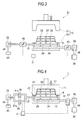
- Fig. 2 is a diagram showing an example of disposition of the ejection holes 27 and the suction holes 33 made in the lower mold 12. Note that the projecting portion is omitted in Fig. 2 . As shown in Fig. 2 , the plurality of ejection holes 27 with a diameter Ds are made at an interval I in the surface of the lower mold 12. Further, the suction hole 33 with a diameter Da is made in a center of four ejection holes 27 positioned rectangularly. Therefore, almost the same numbers of the ejection holes 27 and suction holes 33 are made in the lower mold 12.
- the diameter Da of the suction hole 33 is made larger than the diameter Ds of the ejection hole 27.
- the diameter Da of the suction hole 33 it is possible to suck the cooling water after cooling from the suction hole 33 without accumulation even if the ejection amount from the ejection hole 27 increases.
- the cooling water ejected from the plurality of ejection holes 27 is sucked from the suction hole 33 without accumulation even if the cooling water gathers to one suction hole 33.
- the supply pipe 21 is branched into the first branch pipe 21a and the second branch pipe 21b halfway, the opening/closing valve 25 is provided in the first branch pipe 21a, the opening/closing valve 26 is provided in the second branch pipe 21b, and the opening/closing valve 37 is provided also in the suction pipe 31, but it should be noted that the present invention is not limited to the above configuration.
- Fig. 3 is a diagram schematically showing a configuration of a hot press forming apparatus 41.
- a supply pipe 21 is not branched, the supply pipe 21 being provided with a flow amount regulation valve 42 such as a ball valve which can regulate a flow amount in correspondence with an opening degree of the valve, and a suction pipe 31 is also similarly provided with a flow amount regulation valve 43.
- the flow amount regulation valve may be used instead of the opening/closing valve.
- a steel sheet K having been heated to 900°C, for example, in advance is placed at a predetermined position of the lower mold 12 by a delivery unit (not shown).
- the upper mold 11 is lowered to the bottom dead center while pushing down the steel sheet K vertically downward, so that forming of the steel sheet K is carried out.
- the supply pump 22 and the suction pump 32 already work.
- the upper mold 11 is held at a time that the upper mold 11 is lowered to the bottom dead center while pushing down the steel sheet K vertically downward, and first, the opening/closing valve 25 is opened, so that cooling water of a predetermined flow amount is supplied from the first branch pipe 21a and the supply pipe 21 to the supply path 28 inside the lower mold 12. Therefore, the cooling water is ejected/supplied from the ejection hole 27 into the gap between the steel sheet K and the surface of the lower mold 12 (precooling). Then, the opening/closing valve 37 of the suction side is also opened.
- the opening/closing valve 26 since the opening/closing valve 26 is kept closed, an ejection amount per unit time period from the ejection hole 27 is suppressed compared with a time of main cooling which will be described later.
- the cooling water supplied into the gap between the steel sheet K and the lower mold 12 takes heat from the steel sheet K, and part thereof is vaporized and dispersed from a gap between the upper mold 11 and the lower mold 12.
- the remaining cooling water is discharged to the outside of the apparatus, from the suction hole 33 through the suction path 34 and via the suction pipe 31.
- the opening/closing valve 26 of the supply side is opened while the opening/closing valve 25 is kept in a state of being opened. Therefore, in addition to the cooling water from the first branch pipe 21a, cooling water from the second branch pipe 21b is also supplied, so that the flow amount of the cooling water supplied to the supply path 28 is increased. Therefore, the ejection amount per unit time period of the cooling water ejected from the ejection hole 27 is increased by that amount (main cooling).
- the opening/closing valves 25, 26 are closed, and the opening/closing valve 37 is also closed.
- an ejection amount of precooling is 1.0 mL/sec by each ejection hole to 3.0 mL/sec by each ejection hole.
- a ratio of a flow amount flowing from only the first branch pipe 21a when only the opening/closing valve 25 is in the state of being opened at a time of precooling to a flow amount flowing from both the first branch pipe 21a and the second branch pipe 21b by opening both the opening/closing valves 25, 26 at a time of main cooling thereafter is 1: 5 to 2: 5.
- a ratio of the ejection amount per unit time period of the cooling water ejected from the ejection hole 27 at the precooling time to the ejection amount per unit time period of the cooling water ejected from the ejection hole 27 at the main cooling time is 1: 5 to 2: 5.
- a ratio of the precooling time that is, a time period during which flowing is done only from the first branch pipe 21a to the main cooling time, that is, a time period during which flowing is done from both the first branch pipe 21a and the second branch pipe 21b is 1: 4 to 4: 1. Therefore, it is preferable that a ratio of the precooling time period to the main cooling time period is 1: 4 to 4: 1.
- the main cooling time period is preferable to be T/5 to 4T/5 from the start. Further, the main cooling time period is preferable to be 1 second to 4 seconds.
- the precooling where the amount supplied of the cooling water from the ejection hole 27 is the flow amount from only the first branch pipe 21a at the beginning of the cooling and subsequently the main cooling where the cooling water is supplied from both the first branch pipe 21a and the second branch pipe 21b. Therefore, it is possible to carry out the precooling in which the ejection amount per unit time period is suppressed.
- rapid cooling is suppressed in the neighborhood of the ejection hole at the beginning of the cooling, and as a result of being cooled gradually, a temperature difference in the neighborhood of the ejection hole and in a position apart from the ejection hole can be decreased. Further, as a result of being cooled gradually, it is possible to suppress bumping or entrainment of air at the beginning of the cooling.
- Fig. 5 shows fluctuation of each ejection amount of a conventional method, a step method, and a continuous method.
- the step method is an operational example of the hot press forming apparatus 1 of Fig. 1 .
- the continuous method is an operational example of the hot press forming apparatus 41 of Fig. 3 .
- a cooling start time at the bottom dead center (position of 0.0 in a horizontal axis in a graph of Fig. 5 ) until 1 second passes only the opening/closing valve 25 is opened and supply is carried out at an ejection amount of 2 mL/sec by each ejection hole (precooling). Thereafter, until 2 seconds pass, the opening/closing valve 26 is also opened, and supply is carried out at an ejection amount of 7 mL/sec by each ejection hole in total (main cooling).
- the flow amount regulation valve 42 is controlled and from a cooling start time until 0.8 seconds pass, supply is carried out at an ejection amount of 1.5 mL/sec by each ejection hole (precooling). Thereafter, from a time that 0.8 seconds have passed, an opening degree of the flow amount regulation valve 42 is made gradually large to increase the flow amount, the opening degree being made gradually large until 1.4 seconds pass. Thereafter, until 1.8 seconds pass, supply is carried out at an ejection amount of 8.0 mL/sec by each ejection hole at a maximum opening degree (main cooling). Thereafter, the flow amount regulation valve 42 is gradually closed, and at a time that 2.0 seconds pass, the flow amount regulation valve 42 is closed.
- Fig. 6 shows a state where the valve element 44 is fully closed.
- Fig. 7 shows a state where the valve element 44 is in the middle between being fully closed and being fully opened.
- Fig. 8 shows a state where the valve element 44 is fully opened.
- the flow amount regulation valve 42 is controlled by a control device C.
- the control device C detects the opening degree of the valve element 44 via an angle detection sensor (not shown) or the like. As shown in Fig. 6 to Fig. 8 , the control device C can indicate the detected opening degree by an arrow 45 or the like, for example.
- the control device C opens/closes the valve element 44 via a valve opening/closing drive mechanism (not shown) such as an electric motor. More specifically, the control device C can materialize ejection amount control of the continuous method of Fig. 5 by opening/closing the valve element 44 based on a program in which a cooling time period and an opening degree of the valve element 44 are correlated and stored.
- an ejection amount pattern of the continuous method of Fig. 5 can be set to be an arbitrary pattern only by changing the program. Therefore, a distortion of a shape of a steel sheet and quality unevenness can be adjusted precisely.
- the number of the flow amount regulation valve 42 to be provided is not limited to one, but, as shown in Fig. 9 , it is possible that a plurality of supply pipes 21 to a mold are provided in parallel and that flow amount regulation valves 42a, 42b are provided in each of the supply pipes 21. In such a case, it is possible to regulate a flow amount for each supply pipe 21, and for a large mold in particular, the ejection amount pattern of the continuous method can be set to be an arbitrary pattern for each region of the mold. For example, it is possible to change an ejection amount of cooling water for each supply pipe 21 by making an opening degree of a valve element 44 in the flow amount regulation valve 42a be 45 degrees as shown in Fig.
- an ejection amount of cooling water of an entire mold may be made uniform by synchronizing or intentionally differentiating opening/closing speeds of a plurality of flow amount regulation valves provided in a supply pipe of cooling water, the supply pipe leading to a supply path inside the mold.
- a control device C controls the plurality of flow amount control valves
- a flow amount regulation type supply pump 46 capable of regulating a supply flow amount and a flow amount regulation type suction pump 47 capable of regulating a suction flow amount.
- flow amount regulation type supply pump 46 flow amount regulation similar to that by the flow amount regulation valve is possible.
- the flow amount regulation type supply pump 46 and the flow amount regulation type suction pump 47 it is possible to use ones in which the numbers of rotation of the pumps are changeable by inverter control, for example. In such a case, a control device C controls the number of rotation of the pump.
- the cooling water such as water is used as the refrigerant
- the refrigerant is not limited thereto.
- the refrigerant it is possible to use gas, vapor, or gas-liquid mixture in which water in mist form is mixed in gas.
- an aluminum-plated steel sheet of 1.4 mm in sheet thickness consisting of chemical components, in mass%, C: 0.22%, Mn: 1.2%, Cr: 0.2%, B: 0.002%, and remaining being iron and an inevitable impurity. Further, the steel sheet is heated to 900°C and cooled to 250°C, a target temperature.
- cooling water (tap water or industrial water) of 5°C to 25°C in temperature is used.
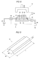
- a shape of a formed product by press forming is targeted to a component whose sectional rigidity is low among framework parts of an automobile. More specifically, as shown in Fig. 13 , that component is a formed product 51 with a hat-shaped cross section having outward flanges, and a length L is 400 mm, a width WL is 140 mm, a height H is 30 mm, and a width Wh of a hat shape is 70 mm.
- an interval I between the ejection holes 27 is 30 mm, a diameter Ds of the ejection hole 27 is 1 mm, and a diameter Da of the suction hole 33 is 4 mm. Further, a height (distance from the surface of the mold to a top surface of the projecting portion) of the projecting portion is 0.5 mm.
- An ejection amount per unit time period of the cooling water is set to be changed in two stages in precooling and main cooling.
- the precooling is carried out in which only the opening/closing valve 25 is opened and the ejection amount per unit time period is suppressed.
- the main cooling is carried out in which the opening/closing valve 26 is also opened and the ejection amount per unit time period is increased.
- cooling is carried out in seven patterns of ratios of the ejection amount of the precooling to the ejection amount of the main cooling. More specifically, as shown in Table 1, the patterns are “precooling: main cooling, 0.4: 2", “precooling: main cooling, 1: 5", “precooling: main cooling, 2: 5", “precooling: main cooling, 2: 10", “precooling: main cooling, 3: 10", “precooling: main cooling, 3: 15”, and “precooling: main cooling, 4: 10".
- precooling main cooling, 0.4: 2
- ejection amount of the precooling is 0.4 mL/sec by each ejection hole and that the ejection amount of the main cooling is 2 mL/sec by each ejection hole.
- an ejection time period that is, a cooling time period by the cooling water, is set to be 2 seconds to 5 seconds within a range of 5 seconds or less where an effect of a high productivity can be obtained.
- the ejection time period is set to be 5 seconds, and a ratio of a precooling time period to a main cooling time period is changed by a unit of 1 second, and cooling is carried out in six patterns. More specifically, as shown in Table 1, the patterns are “precooling time period is 0 second, main cooling time period is 5 seconds", “precooling time period is 1 second, main cooling time period is 4 seconds", “precooling time period is 2 seconds, main cooling time period is 3 seconds", “precooling time period is 3 seconds, main cooling time period is 2 seconds”, “precooling time period is 4 second, main cooling time period is 1 second”, and “precooling time period is 5 seconds, main cooling time period is 0 second”.
- precooling time period is 0 second, main cooling time period is 5 seconds
- main cooling time period is 5 seconds
- main cooling time period is 1 seconds
- main cooling time period is 4 seconds
- main cooling time indicates that the cooling where the precooling time is 1 second and the main cooling time is 4 seconds is carried out.
- precooling time is 5 seconds
- main cooling time is 0 second
- main cooling time indicates that the cooling is carried out for 5 seconds in a state of precooling. In other words, the ejection amount is merely reduced in the conventional method of Fig. 5 .
- a mark "A” shown in Table 1 indicates a bad shape accuracy due to insufficient cooling.
- a mark “ ⁇ ” indicates a bad shape accuracy due to rapid cooling.
- a mark “ ⁇ ” indicates insufficient cooling but that whether a forming accuracy is good or bad is divided.
- a mark “ ⁇ ” indicates rapid cooling but that whether a shape accuracy is good or bad is divided.
- a mark “ ⁇ ” indicates a good shape accuracy because of good cooling.
- a mark “ ⁇ ” indicates that a shape accuracy is stably good because of good cooling.
- the good shape accuracy means that an accuracy of a target dimension is ⁇ 0.5 mm or less at all positions of a formed product.
- the shape accuracy being stably good means that an accuracy of a target dimension is ⁇ 0.4 mm or less at all positions of a formed product.
- the bad shape accuracy means that an accuracy of a target dimension exceeds ⁇ 0.5 mm in at least a part of a formed product.
- whether the shape accuracy is good or bad being divided means that an accuracy of a target dimension exceeds ⁇ 0.5 mm in at least a part of a formed product but that a region of exceeding is clear and that it is possible to use the formed product depending on intended use of the formed product.
- the ratio of the precooling time period to the main cooling time period is changed, a stable region cannot be obtained when the precooling time period is 0 second and the main cooling time period is 0 second.
- T a total time period from the start of cooling until supply of cooling water is stopped
- the ratio of the precooling time period to the main cooling time period is further set to be 2: 3 to 3: 2, it is possible to make shape accuracies of all the obtained formed products good. In other words, in order for the good shape accuracy, it is preferable to set the ratio of the precooling time period to the main cooling time period to be 2: 3 to 3: 2.
- a steel sheet is an aluminum-based plated thin steel sheet or a galvanized thin steel sheet to which plating is applied so that scale is not generated when heated.
- a sheet thickness it is preferable to be a thin steel sheet of 1 mm to 2 mm which is used for a component of an automobile.
- a temperature of the steel sheet it is preferable that the steel sheet has been heated for quenching (generating a martensite structure by rapid cooing), to a temperature at which a ferrite structure does not precipitate (for example, 700°C) or more to 1000°C or less.
- a refrigerant is water since water is comparatively easy to obtain, and it is preferable that its temperature is 5°C to 25°C being a room temperature.
- an ejection time period that is, a cooling time period being a total of a precooling time period and a main cooling time period is preferable to be 2 seconds or more in order to make ejected cooling water spread, and is preferable to be 5 seconds or less in order to obtain an effect of a high productivity.
- the diameter Ds of the ejection hole 27 is preferable to be 1 mm to 4 mm in order to make the ejection amount per unit time period of the precooling be 1 mL/sec to 3 mL/sec.
- the present invention is not limited thereto and a configuration is possible in which the ejection hole 27 and the suction hole 33 are provided in at least one of the upper mold 11 and the lower mold 12.
- the present invention is not limited to such a case but the number of the ejection hole 27 may be one depending on a size of a formed product.
- the present invention is useful in hot press forming a thin steel sheet.
Landscapes
- Engineering & Computer Science (AREA)
- Mechanical Engineering (AREA)
- Physics & Mathematics (AREA)
- Thermal Sciences (AREA)
- Shaping Metal By Deep-Drawing, Or The Like (AREA)
- Heat Treatment Of Articles (AREA)
- Press Drives And Press Lines (AREA)
- Mounting, Exchange, And Manufacturing Of Dies (AREA)
- Heat Treatments In General, Especially Conveying And Cooling (AREA)
Abstract
Description
- The present invention relates to a cooling method for hot press forming of a thin steel sheet and to a hot press forming apparatus.
- Hot press forming is recently adopted as a steel sheet forming means for an automobile component or the like using a high-tensile steel sheet. In hot press forming, as a result of press forming a steel sheet at a high temperature, forming is carried out in a stage where a deformation resistance is low, and quench hardening by rapid cooling is done, and therefore, it is possible to obtain a component or the like which has a high strength and a high shape accuracy, without generating a forming defect such as a deformation after forming.
- In hot press forming, a steel sheet having been heated to a predetermined temperature by a heating furnace in advance is supplied to a mold, and in a state where the steel sheet is placed on a die or floated by a jig such as a lifter built in the mold, a punch is lowered to a bottom dead center, and then a refrigerant such as water, for example, is supplied to between the steel sheet and the mold to cool the steel sheet rapidly. Therefore, a surface of the mold is provided with a plurality of independent projecting portions with a constant height and the inside of the mold is provided with a channel of water communicated with ejection holes of the refrigerant which are provided in a plurality of places in the surface of the mold and a channel for sucking the supplied water. In a conventional cooling method for hot press forming of a thin steel sheet, since the same flow amount is kept while cooling is carried out by flowing cooling water, the same ejection amount is ejected from each ejection hole during a cooling time period.
- In a case where hot press forming is carried out by using a mold of such a configuration, it is considered to shorten a cooling time period by increasing a flow amount of cooling water, in order to further improve a productivity. However, it is found that a variation of qualities such as a formed shape (warpage) and a quenching characteristic occurs depending on a region. This is caused by nonuniformity of cooling due to a difference in cooling speed by the flow of the refrigerant in a neighborhood of the ejection hole and its periphery. In other words, the difference in cooling speed generates a thermal stress, which causes the quality to vary. Further, as a result of further study by the inventors, it is found that there is cooling unevenness in a circular state centering on the ejection hole. It is considered that if cooling water is ejected at a predetermined ejection amount from the beginning of cooling, bumping or entrainment of air occurs concentrically centering on the ejection hole, thereby to generate cooling unevenness. Therefore, a device of some kind is necessary with regard to an amount supplied of the refrigerant.
- Note that the applicant has already suggested a hot press forming method of
Patent Literature 1 with regard to supply control of a refrigerant in a hot press forming method. In the above hot press forming method, a heated thick steel sheet is placed on a rapid cooling mold, the refrigerant is supplied to the thick steel sheet to carry out rapid cooling while the rapid cooling mold is held at a bottom dead center, and thereafter, supply of the refrigerant is controlled in a state where the rapid cooling mold is held at the bottom dead center. More specifically, stopping of supply of the refrigerant and conducting supply of the refrigerant again after a predetermined time period passes is repeated at least once or more, or a predetermined supply flow amount of the refrigerant is once reduced halfway and the supply flow amount of the refrigerant is increased again after a predetermined time period passes. - However, in the hot press forming method of
Patent Literature 1, a target steel sheet is what is called a thick sheet and an object thereof is to make a formed product in which a strength is changed in a thickness direction of the steel sheet. Therefore, without a countermeasure, in hot press forming of a thin steel sheet, it is impossible to improve a distortion of a shape of the steel sheet or quality unevenness caused by nonuniformity of cooling due to the aforementioned difference in cooling speed which occurs in a neighborhood of an ejection hole and its periphery. - Patent Literature 1: Japanese Laid-open Patent Publication No.
2011-143437 - The present invention is made in view of the above circumstances, and an object thereof is to suppress a distortion of a shape and a variation of a quality caused by nonuniformity of cooling, in hot press forming a thin steel sheet.
- As a result of keen study and experiments by the inventors it is proved that a distortion of a shape or the like due to nonuniformity of cooling is caused by occurrence of a temperature variation as a result of cooling being promptly carried out in a neighborhood of an ejection hole of a refrigerant while a cooling speed becoming slow at a position apart from the ejection hole. Further, it is newly found that such a variation changes by change of a flow amount of the supplied refrigerant.
- In view of the above findings, the present invention is a cooling method for hot press forming in which a thin steel sheet is cooled by supplying a refrigerant to an ejection hole of a surface of a mold which ejection hole is communicated from a supply path inside the mold in hot press forming the heated thin steel sheet, the cooling method for hot press forming including: carrying out precooling in which an ejection amount per unit time period of the refrigerant from the ejection hole is suppressed; and thereafter, carrying out main cooling by increasing the ejection amount per unit time period, when the thin steel sheet is cooled by supplying the refrigerant to the ejection hole in a state where the heated thin steel sheet is placed on the mold and held at a bottom dead center.
- Further, the present invention is a hot press forming apparatus which cools a thin steel sheet by supplying a refrigerant to an ejection hole of a surface of a mold which ejection hole is communicated from a supply path inside the mold in hot press forming the heated thin steel sheet, the hot press forming apparatus carrying out precooling in which an ejection amount per unit time period is suppressed, and thereafter, carrying out main cooling by increasing the ejection amount per unit time period of the refrigerant from the ejection hole, when the thin steel sheet is cooled by supplying the refrigerant to the ejection hole in a state where the heated thin steel sheet is placed on the mold and held at a bottom dead center.
- By carrying out the precooling in which the ejection amount per unit time period is suppressed as described above, it is possible to suppress excessive cooling in a neighborhood of the ejection hole. Further, by carrying out the precooling in which the ejection amount per unit time period is suppressed, it is possible to suppress bumping or entrainment of air of the beginning of the cooling. Therefore, by main cooling thereafter, uniform cooling can be materialized to an entire of the thin steel sheet.
- According to the present invention, it is possible to suppress a distortion of a shape or a variation of a quality caused by nonuniformity of cooling in hot press forming a thin steel sheet.
-
- [
Fig. 1] Fig. 1 is a diagram schematically showing a configuration of a hot press forming apparatus; - [
Fig. 2] Fig. 2 is a diagram showing an example of disposition of ejection holes and suction holes; - [
Fig. 3] Fig. 3 is a diagram schematically showing a configuration of a hot press forming apparatus having a flow amount regulation valve; - [
Fig. 4] Fig. 4 is a diagram showing a state where an upper mold of the hot press forming apparatus ofFig. 1 is at a bottom dead center; - [
Fig. 5] Fig. 5 is a graph showing an example of flow amount control of cooling water; - [
Fig. 6] Fig. 6 is a diagram showing a state where an opening degree of the flow amount regulation valve is fully closed; - [
Fig. 7] Fig. 7 is a diagram showing a state where the opening degree of the flow amount regulation valve is medium; - [
Fig. 8] Fig. 8 is a diagram showing a state where the opening degree of the flow amount regulation valve is fully opened; - [
Fig. 9] Fig. 9 is a diagram schematically showing a configuration in which a plurality of supply pipes are provided; - [
Fig. 10] Fig. 10 is a diagram showing a state where the opening degree of the flow amount regulation valve is 45 degrees; - [
Fig. 11] Fig. 11 is a diagram showing a state where the opening degree of the flow amount regulation valve is 22.5 degrees; - [
Fig. 12] Fig. 12 is a diagram schematically showing a configuration of a hot press forming apparatus having a supply pipe capable of flow amount regulation; and - [
Fig. 13] Fig. 13 is a diagram showing an example of a shape of a formed product. - Hereinafter, an embodiment of the present invention will be described.
-
Fig. 1 is a diagram schematically showing a configuration of a hotpress forming apparatus 1 of the present embodiment. The hotpress forming apparatus 1 has an upper mold 11 (first mold) and a lower mold 12 (second mold) which constitute a press forming mold 10 for press forming a steel sheet (thin steel sheet) K. Note that the thin steel sheet means a steel sheet with a sheet thickness of less than 3 mm. - In the present embodiment, a plurality of independent projecting portions (not shown) with a constant height are provided in a surface of the
lower mold 12, and gaps are made between the steel sheet K and thelower mold 12 at a bottom dead center. Cooling water as a refrigerant is supplied into the gaps. Theupper mold 11 can be raised and lowered freely in a vertical direction at a predetermined pressure by a raising and lowering mechanism (not shown). Note that the steel sheet K is heated to a predetermined temperature, for example, to a temperature of 700°C or more to 1000°C or less by a heating apparatus (not shown) in advance, and is conveyed to the hotpress forming apparatus 1. The conveyed steel sheet is placed at a predetermined position of thelower mold 12 based on a positioning pin (not shown) set in a predetermined position of thelower mold 12, for example. - To the
lower mold 12 are connected/installed asupply pipe 21 of the cooling water to be the refrigerant and asuction pipe 31 to suck surplus cooling water. Thesupply pipe 21 is to supply the cooling water into thelower mold 12 at a predetermined pressure by asupply pump 22. Thesuction pipe 31 is to discharge the cooling water which has been supplied to between thelower mold 12 and the steel sheet K to the outside of the apparatus by asuction pump 32. - The
supply pump 22 intakes the cooling water from a coolingwater supply source 23 through anintake pipe 24. Theintake pipe 24 is connected to thesupply pipe 21 in a downstream side of thesupply pump 22. Thesupply pipe 21 is branched into afirst branch pipe 21a and asecond branch pipe 21b in a downstream side of a connected portion to theintake pipe 24. Thefirst branch pipe 21a and thesecond branch pipe 21b are a plurality of supply systems of the refrigerant to thesupply pipe 21. Thefirst branch pipe 21a and thesecond branch pipe 21b are provided with opening/closing valves first branch pipe 21a and thesecond branch pipe 21b are joined again in a downstream side of the opening/closing valves supply pipe 21 is communicated with a plurality of ejection holes 27 provided in the surface of thelower mold 12, through asupply path 28 made inside thelower mold 12. - Further, a plurality of suction holes 33 are provided in the surface of the
lower mold 12. Thesuction hole 33 leads to asuction path 34 made inside thelower mold 12 and is communicated with thesuction pipe 31. The cooling water sucked by thesuction pump 32 is discharged to adischarge portion 36 from thesuction pipe 31 through thedischarge pipe 35. Thesuction pipe 31 is provided with an opening/closingvalve 37 of a suction side. - Opening/closing of the opening/
closing valves valve 37 of the suction side are controlled together with an action of theupper mold 11 by a control device C. -
Fig. 2 is a diagram showing an example of disposition of the ejection holes 27 and the suction holes 33 made in thelower mold 12. Note that the projecting portion is omitted inFig. 2 . As shown inFig. 2 , the plurality of ejection holes 27 with a diameter Ds are made at an interval I in the surface of thelower mold 12. Further, thesuction hole 33 with a diameter Da is made in a center of four ejection holes 27 positioned rectangularly. Therefore, almost the same numbers of the ejection holes 27 and suction holes 33 are made in thelower mold 12. - In the present embodiment, the diameter Da of the
suction hole 33 is made larger than the diameter Ds of theejection hole 27. As a result of making the diameter Da of thesuction hole 33 larger, it is possible to suck the cooling water after cooling from thesuction hole 33 without accumulation even if the ejection amount from theejection hole 27 increases. Further, as a result of making the diameter Da of thesuction hole 33 larger, the cooling water ejected from the plurality of ejection holes 27 is sucked from thesuction hole 33 without accumulation even if the cooling water gathers to onesuction hole 33. - In the aforementioned hot
press forming apparatus 1 of the embodiment, thesupply pipe 21 is branched into thefirst branch pipe 21a and thesecond branch pipe 21b halfway, the opening/closingvalve 25 is provided in thefirst branch pipe 21a, the opening/closingvalve 26 is provided in thesecond branch pipe 21b, and the opening/closingvalve 37 is provided also in thesuction pipe 31, but it should be noted that the present invention is not limited to the above configuration. -
Fig. 3 is a diagram schematically showing a configuration of a hotpress forming apparatus 41. In the hotpress forming apparatus 41, asupply pipe 21 is not branched, thesupply pipe 21 being provided with a flowamount regulation valve 42 such as a ball valve which can regulate a flow amount in correspondence with an opening degree of the valve, and asuction pipe 31 is also similarly provided with a flowamount regulation valve 43. In this way, the flow amount regulation valve may be used instead of the opening/closing valve. - Next, an operation example of the hot
press forming apparatus 1 shown inFig. 1 will be described. - First, a steel sheet K having been heated to 900°C, for example, in advance is placed at a predetermined position of the
lower mold 12 by a delivery unit (not shown). Next, as shown inFig. 4 , theupper mold 11 is lowered to the bottom dead center while pushing down the steel sheet K vertically downward, so that forming of the steel sheet K is carried out. At this time, thesupply pump 22 and thesuction pump 32 already work. - The
upper mold 11 is held at a time that theupper mold 11 is lowered to the bottom dead center while pushing down the steel sheet K vertically downward, and first, the opening/closingvalve 25 is opened, so that cooling water of a predetermined flow amount is supplied from thefirst branch pipe 21a and thesupply pipe 21 to thesupply path 28 inside thelower mold 12. Therefore, the cooling water is ejected/supplied from theejection hole 27 into the gap between the steel sheet K and the surface of the lower mold 12 (precooling). Then, the opening/closingvalve 37 of the suction side is also opened. Here, at a time of precooling, since the opening/closingvalve 26 is kept closed, an ejection amount per unit time period from theejection hole 27 is suppressed compared with a time of main cooling which will be described later. The cooling water supplied into the gap between the steel sheet K and thelower mold 12 takes heat from the steel sheet K, and part thereof is vaporized and dispersed from a gap between theupper mold 11 and thelower mold 12. The remaining cooling water is discharged to the outside of the apparatus, from thesuction hole 33 through thesuction path 34 and via thesuction pipe 31. - Next, after a predetermined time period passes, the opening/closing
valve 26 of the supply side is opened while the opening/closingvalve 25 is kept in a state of being opened. Therefore, in addition to the cooling water from thefirst branch pipe 21a, cooling water from thesecond branch pipe 21b is also supplied, so that the flow amount of the cooling water supplied to thesupply path 28 is increased. Therefore, the ejection amount per unit time period of the cooling water ejected from theejection hole 27 is increased by that amount (main cooling). - Next, after a predetermined time period passes and the steel sheet K is cooled to a predetermined temperature, the opening/
closing valves valve 37 is also closed. - Note that in a cooling process as above, it is preferable that an ejection amount of precooling is 1.0 mL/sec by each ejection hole to 3.0 mL/sec by each ejection hole. Further, it is preferable that a ratio of a flow amount flowing from only the
first branch pipe 21a when only the opening/closingvalve 25 is in the state of being opened at a time of precooling to a flow amount flowing from both thefirst branch pipe 21a and thesecond branch pipe 21b by opening both the opening/closing valves ejection hole 27 at the precooling time to the ejection amount per unit time period of the cooling water ejected from theejection hole 27 at the main cooling time is 1: 5 to 2: 5. - Further, it is preferable that a ratio of the precooling time, that is, a time period during which flowing is done only from the
first branch pipe 21a to the main cooling time, that is, a time period during which flowing is done from both thefirst branch pipe 21a and thesecond branch pipe 21b is 1: 4 to 4: 1. Therefore, it is preferable that a ratio of the precooling time period to the main cooling time period is 1: 4 to 4: 1. Here, when a total time period from the start of cooling to the stop of cooling is indicated as T, the main cooling time period is preferable to be T/5 to 4T/5 from the start. Further, the main cooling time period is preferable to be 1 second to 4 seconds. - By the flow amount control of the cooling water as above, there become possible the precooling where the amount supplied of the cooling water from the
ejection hole 27 is the flow amount from only thefirst branch pipe 21a at the beginning of the cooling and subsequently the main cooling where the cooling water is supplied from both thefirst branch pipe 21a and thesecond branch pipe 21b. Therefore, it is possible to carry out the precooling in which the ejection amount per unit time period is suppressed. By carrying out the precooling, rapid cooling is suppressed in the neighborhood of the ejection hole at the beginning of the cooling, and as a result of being cooled gradually, a temperature difference in the neighborhood of the ejection hole and in a position apart from the ejection hole can be decreased. Further, as a result of being cooled gradually, it is possible to suppress bumping or entrainment of air at the beginning of the cooling. - Therefore, it is possible to suppress a distortion of a shape of a steel sheet or quality unevenness caused by temperature unevenness.
- Next, an ejection amount control example of the cooling water of the hot
press forming apparatuses Fig 5. Fig. 5 shows fluctuation of each ejection amount of a conventional method, a step method, and a continuous method. - In the conventional method, the same ejection amount is maintained from the beginning until the stop of supply of cooling water. The step method is an operational example of the hot
press forming apparatus 1 ofFig. 1 . The continuous method is an operational example of the hotpress forming apparatus 41 ofFig. 3 . - As shown in
Fig. 5 , in the step method (hotpress forming apparatus 1 ofFig. 1 ), from a cooling start time at the bottom dead center (position of 0.0 in a horizontal axis in a graph ofFig. 5 ) until 1 second passes, only the opening/closingvalve 25 is opened and supply is carried out at an ejection amount of 2 mL/sec by each ejection hole (precooling). Thereafter, until 2 seconds pass, the opening/closingvalve 26 is also opened, and supply is carried out at an ejection amount of 7 mL/sec by each ejection hole in total (main cooling). - Further, in the continuous method (hot
press forming apparatus 41 ofFig. 3 ), the flowamount regulation valve 42 is controlled and from a cooling start time until 0.8 seconds pass, supply is carried out at an ejection amount of 1.5 mL/sec by each ejection hole (precooling). Thereafter, from a time that 0.8 seconds have passed, an opening degree of the flowamount regulation valve 42 is made gradually large to increase the flow amount, the opening degree being made gradually large until 1.4 seconds pass. Thereafter, until 1.8 seconds pass, supply is carried out at an ejection amount of 8.0 mL/sec by each ejection hole at a maximum opening degree (main cooling). Thereafter, the flowamount regulation valve 42 is gradually closed, and at a time that 2.0 seconds pass, the flowamount regulation valve 42 is closed. - Note that as the flow
amount regulation valve 42 which can materialize ejection amount control of the continuous method, it is possible to use one shown inFig. 6 to Fig. 8 which is capable of freely regulating an opening degree of avalve element 44. -
Fig. 6 shows a state where thevalve element 44 is fully closed.Fig. 7 shows a state where thevalve element 44 is in the middle between being fully closed and being fully opened.Fig. 8 shows a state where thevalve element 44 is fully opened. The flowamount regulation valve 42 is controlled by a control device C. The control device C detects the opening degree of thevalve element 44 via an angle detection sensor (not shown) or the like. As shown inFig. 6 to Fig. 8 , the control device C can indicate the detected opening degree by anarrow 45 or the like, for example. Further, the control device C opens/closes thevalve element 44 via a valve opening/closing drive mechanism (not shown) such as an electric motor. More specifically, the control device C can materialize ejection amount control of the continuous method ofFig. 5 by opening/closing thevalve element 44 based on a program in which a cooling time period and an opening degree of thevalve element 44 are correlated and stored. - As described above, by using the flow
amount regulation valve 42 capable of regulating the flow amount continuously, it is possible to moderate ejection of the cooling water at the precooling start time and transition of the ejection amount from the precooling to the main cooling. Further, as a result that the control device C carries out ejection amount control based on the program, an ejection amount pattern of the continuous method ofFig. 5 can be set to be an arbitrary pattern only by changing the program. Therefore, a distortion of a shape of a steel sheet and quality unevenness can be adjusted precisely. - Further, the number of the flow
amount regulation valve 42 to be provided is not limited to one, but, as shown inFig. 9 , it is possible that a plurality ofsupply pipes 21 to a mold are provided in parallel and that flowamount regulation valves supply pipes 21. In such a case, it is possible to regulate a flow amount for eachsupply pipe 21, and for a large mold in particular, the ejection amount pattern of the continuous method can be set to be an arbitrary pattern for each region of the mold. For example, it is possible to change an ejection amount of cooling water for eachsupply pipe 21 by making an opening degree of avalve element 44 in the flowamount regulation valve 42a be 45 degrees as shown inFig. 10 and making an opening degree of avalve element 44 in the flowamount regulation valve 42b be 22.5 degrees as shown inFig. 11 . Therefore, even in a case of carrying out press forming by a large mold, it is possible to suppress a difference in cooling (quenching) characteristic which is generated because a shape is different for each region of the mold. Further, it is possible to obtain a different cooling (quenching) characteristic for each region of the mold by intentionally generating a difference in ejection amount of the cooling water. - Further, an ejection amount of cooling water of an entire mold may be made uniform by synchronizing or intentionally differentiating opening/closing speeds of a plurality of flow amount regulation valves provided in a supply pipe of cooling water, the supply pipe leading to a supply path inside the mold. In such a case, a control device C controls the plurality of flow amount control valves
- Further, in a case of a small mold, as shown in
Fig. 12 , it is possible to use a flow amount regulationtype supply pump 46 capable of regulating a supply flow amount and a flow amount regulationtype suction pump 47 capable of regulating a suction flow amount. By using the flow amount regulationtype supply pump 46, flow amount regulation similar to that by the flow amount regulation valve is possible. As the flow amount regulationtype supply pump 46 and the flow amount regulationtype suction pump 47, it is possible to use ones in which the numbers of rotation of the pumps are changeable by inverter control, for example. In such a case, a control device C controls the number of rotation of the pump. - As described above, by either of the step method (hot
press forming apparatus 1 ofFig. 1 ) and the continuous method (hotpress forming apparatus 41 ofFig. 3 ), it is possible to suppress a distortion of a shape of a steel sheet or quality unevenness caused by temperature unevenness due to rapid cooling in a neighborhood of an ejection hole at the beginning of cooling. - In the aforementioned embodiment, a case where the cooling water such as water is used as the refrigerant is described, but it should be noted that the refrigerant is not limited thereto. In other words, as the refrigerant, it is possible to use gas, vapor, or gas-liquid mixture in which water in mist form is mixed in gas.
- Hereinafter, an experiment example using the hot
press forming apparatus 1 ofFig. 1 will be described. - Here, as an experiment condition, with regard to a steel sheet, there is used an aluminum-plated steel sheet of 1.4 mm in sheet thickness, consisting of chemical components, in mass%, C: 0.22%, Mn: 1.2%, Cr: 0.2%, B: 0.002%, and remaining being iron and an inevitable impurity. Further, the steel sheet is heated to 900°C and cooled to 250°C, a target temperature.
- As the refrigerant, cooling water (tap water or industrial water) of 5°C to 25°C in temperature is used.
- A shape of a formed product by press forming is targeted to a component whose sectional rigidity is low among framework parts of an automobile. More specifically, as shown in
Fig. 13 , that component is a formedproduct 51 with a hat-shaped cross section having outward flanges, and a length L is 400 mm, a width WL is 140 mm, a height H is 30 mm, and a width Wh of a hat shape is 70 mm. - Further, in the
lower mold 12, an interval I between the ejection holes 27 is 30 mm, a diameter Ds of theejection hole 27 is 1 mm, and a diameter Da of thesuction hole 33 is 4 mm. Further, a height (distance from the surface of the mold to a top surface of the projecting portion) of the projecting portion is 0.5 mm. - An ejection amount per unit time period of the cooling water is set to be changed in two stages in precooling and main cooling. In other words, from the beginning of cooling until a predetermined time period passes, the precooling is carried out in which only the opening/closing
valve 25 is opened and the ejection amount per unit time period is suppressed. Thereafter, the main cooling is carried out in which the opening/closingvalve 26 is also opened and the ejection amount per unit time period is increased. - In the experiment example, cooling is carried out in seven patterns of ratios of the ejection amount of the precooling to the ejection amount of the main cooling. More specifically, as shown in Table 1, the patterns are "precooling: main cooling, 0.4: 2", "precooling: main cooling, 1: 5", "precooling: main cooling, 2: 5", "precooling: main cooling, 2: 10", "precooling: main cooling, 3: 10", "precooling: main cooling, 3: 15", and "precooling: main cooling, 4: 10". Here, "precooling: main cooling, 0.4: 2", for example, indicates that the ejection amount of the precooling is 0.4 mL/sec by each ejection hole and that the ejection amount of the main cooling is 2 mL/sec by each ejection hole.
- Further, an ejection time period, that is, a cooling time period by the cooling water, is set to be 2 seconds to 5 seconds within a range of 5 seconds or less where an effect of a high productivity can be obtained.
- In the experiment example, the ejection time period is set to be 5 seconds, and a ratio of a precooling time period to a main cooling time period is changed by a unit of 1 second, and cooling is carried out in six patterns. More specifically, as shown in Table 1, the patterns are "precooling time period is 0 second, main cooling time period is 5 seconds", "precooling time period is 1 second, main cooling time period is 4 seconds", "precooling time period is 2 seconds, main cooling time period is 3 seconds", "precooling time period is 3 seconds, main cooling time period is 2 seconds", "precooling time period is 4 second, main cooling time period is 1 second", and "precooling time period is 5 seconds, main cooling time period is 0 second". Here, "precooling time period is 0 second, main cooling time period is 5 seconds" indicates that only the main cooling is carried out from a cooling start time to a cooling end time, without precooling. In other words, the cooling is carried out in the conventional method of
Fig. 5 . Further, "precooling time period is 1 second, main cooling time period is 4 seconds" indicates that the cooling where the precooling time is 1 second and the main cooling time is 4 seconds is carried out. Further, "precooling time is 5 seconds, main cooling time is 0 second" indicates that the cooling is carried out for 5 seconds in a state of precooling. In other words, the ejection amount is merely reduced in the conventional method ofFig. 5 . - With regard to the seven patterns in which the ratio of the ejection amount of the precooling to the ejection amount of the main cooling is changed and the six patterns in which the ratio of the precooling time period to the main cooling time period is changed, a shape accuracy of a formed product is measured for each pattern and a result is shown in Table 1.


- Here, a mark "A" shown in Table 1 indicates a bad shape accuracy due to insufficient cooling. Further, a mark "▼" indicates a bad shape accuracy due to rapid cooling. A mark "Δ" indicates insufficient cooling but that whether a forming accuracy is good or bad is divided. A mark "∇" indicates rapid cooling but that whether a shape accuracy is good or bad is divided. A mark "○" indicates a good shape accuracy because of good cooling. A mark "⊚" indicates that a shape accuracy is stably good because of good cooling. Here, the good shape accuracy means that an accuracy of a target dimension is ±0.5 mm or less at all positions of a formed product. Further, the shape accuracy being stably good means that an accuracy of a target dimension is ±0.4 mm or less at all positions of a formed product. On the other hand, the bad shape accuracy means that an accuracy of a target dimension exceeds ±0.5 mm in at least a part of a formed product. Further, whether the shape accuracy is good or bad being divided means that an accuracy of a target dimension exceeds ± 0.5 mm in at least a part of a formed product but that a region of exceeding is clear and that it is possible to use the formed product depending on intended use of the formed product.
- Based on the result shown in Table 1, in the component having the low sectional rigidity, a stable region cannot be obtained when the ejection amount of the precooling is 0.4 mL/sec by each ejection hole and 4 mL/sec by each ejection hole. In other words, in order to avoid the bad shape accuracy, it is preferable to set the ejection amount per unit time period of the precooling to be 1 mL/sec by each ejection hole to 3 mL/sec by each ejection hole. On this occasion, it is preferable to set a ratio of the ejection amount per unit time period of precooling to an ejection amount per unit time period of main-cooling to be 1: 5 to 2: 5.
- Further, in a case where the ratio of the precooling time period to the main cooling time period is changed, a stable region cannot be obtained when the precooling time period is 0 second and the main cooling time period is 0 second. In other words, in order to avoid the bad shape accuracy, it is preferable to set the ratio of the precooling time period to the main cooling time period to be 1: 4 to 4:1. In other words, when a total time period from the start of cooling until supply of cooling water is stopped is indicated as T, it is preferable to carry out the precooling between T/5 to 4T/5 from the start.
- Further, in addition to the aforementioned preferable cooling condition, if the ratio of the precooling time period to the main cooling time period is further set to be 2: 3 to 3: 2, it is possible to make shape accuracies of all the obtained formed products good. In other words, in order for the good shape accuracy, it is preferable to set the ratio of the precooling time period to the main cooling time period to be 2: 3 to 3: 2.
- In order to apply the aforementioned preferred condition, it is preferable that a condition below is further satisfied. In other words, it is preferable that a steel sheet is an aluminum-based plated thin steel sheet or a galvanized thin steel sheet to which plating is applied so that scale is not generated when heated. With regard to a sheet thickness, it is preferable to be a thin steel sheet of 1 mm to 2 mm which is used for a component of an automobile. Further, with regard to a temperature of the steel sheet, it is preferable that the steel sheet has been heated for quenching (generating a martensite structure by rapid cooing), to a temperature at which a ferrite structure does not precipitate (for example, 700°C) or more to 1000°C or less. Further, it is preferable that a refrigerant is water since water is comparatively easy to obtain, and it is preferable that its temperature is 5°C to 25°C being a room temperature. Further, an ejection time period, that is, a cooling time period being a total of a precooling time period and a main cooling time period is preferable to be 2 seconds or more in order to make ejected cooling water spread, and is preferable to be 5 seconds or less in order to obtain an effect of a high productivity. Note that the diameter Ds of the
ejection hole 27 is preferable to be 1 mm to 4 mm in order to make the ejection amount per unit time period of the precooling be 1 mL/sec to 3 mL/sec. - Note that in a component with a high sectional rigidity, it is expected that "▲", "▼", "Δ", or "∇" changes to "○" or "⊚", the stable region expanding. Further, it is confirmed in the experiment that in the component with the high sectional rigidity, the ejection time period can be shortened to 2 seconds, though not shown in Table 1.
- Hereinabove, the preferred embodiment of the present invention is described, but the present invention is not limited to the aforementioned embodiment. It is obvious that a person skilled in the art can think of various modifications or corrections within the scope of spirit described in the claims, and it is a matter of course that such modifications or corrections belongs to the technical scope of the present invention.
- For example, in the aforementioned embodiment, a case where the
ejection hole 27 and thesuction hole 33 are provided in thelower mold 12 is described, but the present invention is not limited thereto and a configuration is possible in which theejection hole 27 and thesuction hole 33 are provided in at least one of theupper mold 11 and thelower mold 12. - Further, in the aforementioned embodiment, a case where the plurality of ejection holes 27 are made is described, but the present invention is not limited to such a case but the number of the
ejection hole 27 may be one depending on a size of a formed product. - The present invention is useful in hot press forming a thin steel sheet.
Claims (12)
- A cooling method for hot press forming of a thin steel sheet in which the thin steel sheet is cooled by supplying a refrigerant to an ejection hole of a surface of a mold which ejection hole is communicated from a supply path inside the mold in hot press forming the heated thin steel sheet, the cooling method for hot press forming comprising:carrying out precooling in which an ejection amount per unit time period of the refrigerant from the ejection hole is suppressed; andthereafter, carrying out main cooling by increasing the ejection amount per unit time period, when the thin steel sheet is cooled by supplying the refrigerant to the ejection hole in a state where the heated thin steel sheet is placed on the mold and held at a bottom dead center.
- The cooling method for hot press forming of the thin steel sheet according to claim 1,
wherein the ejection amount per unit time period at a precooling time is 1 mL to 3 mL,
wherein a ratio of the ejection amount per unit time period of the refrigerant from the ejection hole of the precooling time to of a main cooling time is 1: 5 to 2: 5, and
wherein a ratio of a precooling time period to a main cooling time period is 1: 4 to 4: 1. - The cooling method for hot press forming of the thin steel sheet according to claim 2, further,
wherein the ratio of the precooling time period to the main cooling time period is 2:3 to 3: 2. - The cooling method for hot press forming of the thin steel sheet according to claim 2 or 3, further,
wherein the thin steel sheet is an aluminum-based plated thin steel sheet or a galvanized thin steel sheet of 1 mm to 2 mm in sheet thickness and is heated to 700°C to 1000°C before the precooling,
wherein the refrigerant is water of 5°C to 25°C, and
wherein a cooling time period obtained by combining the precooling time period and the main cooling time period is 2 seconds to 5 seconds. - A hot press forming apparatus which cools a thin steel sheet by supplying a refrigerant to an ejection hole of a surface of a mold which ejection hole is communicated from a supply path inside the mold in hot press forming the heated thin steel sheet,
the hot press forming apparatus
carrying out precooling in which an ejection amount per unit time period is suppressed, and thereafter, carrying out main cooling by increasing the ejection amount per unit time period of the refrigerant from the ejection hole, when the steel sheet is cooled by supplying the refrigerant to the ejection hole in a state where the heated thin steel sheet is placed on the mold and held at a bottom dead center. - The hot press forming apparatus according to claim 5,
wherein the ejection amount per unit time period at a precooling time is 1 mL to 3 mL,
wherein a ratio of the ejection amount per unit time period of the refrigerant from the ejection hole of the precooling time to of a main cooling time is 1: 5 to 2: 5, and
wherein a ratio of a precooling time period to a main cooling time period is 1: 4 to 4: 1. - The hot press forming apparatus of the thin steel sheet according to claim 6, further,
wherein the ratio of the precooling time period to the main cooling time period is 2: 3 to 3: 2. - The hot press forming apparatus of the thin steel sheet according to claim 6 or 7, further,
wherein the thin steel sheet is an aluminum-basted plated thin steel sheet or a galvanized thin steel sheet of 1 mm to 2 mm in sheet thickness and is heated to 700°C to 1000°C before the precooling,
wherein the refrigerant is water of 5°C to 25°C, and
wherein a cooling time period obtained by combining the precooling time period and the main cooling time period is 2 seconds to 5 seconds. - The hot press forming apparatus of the thin steel sheet according to any one of claims 5 to 8,
wherein a suction hole is made in a center of the four ejection holes positioned rectangularly in the surface of the mold, and
wherein a diameter of the suction hole is larger than a diameter of the ejection hole. - The hot press forming apparatus of the thin steel sheet according to any one of claims 5 to 9,
wherein a plurality of supply systems of the refrigerant are connected to a supply pipe of the refrigerant, the supply pipe leading to the supply path inside the mold, and
wherein an opening/closing valve is provided in each of the supply systems. - The hot press forming apparatus of the thin steel sheet according to any one of claims 5 to 9,
wherein a flow amount regulation valve is provided in the supply pipe of the refrigerant, the supply pipe leading to the supply path inside the mold. - The hot press forming apparatus of the thin steel sheet according to any one of claims 5 to 9,
wherein a supply pump capable of regulating the flow amount is provided in the supply pipe of the refrigerant, the supply pipe leading to the supply path inside the mold.
Applications Claiming Priority (2)
| Application Number | Priority Date | Filing Date | Title |
|---|---|---|---|
| JP2013189218 | 2013-09-12 | ||
| PCT/JP2014/074056 WO2015037657A1 (en) | 2013-09-12 | 2014-09-11 | Hot-press stamping cooling method and hot-press stamping device |
Publications (3)
| Publication Number | Publication Date |
|---|---|
| EP3045236A1 true EP3045236A1 (en) | 2016-07-20 |
| EP3045236A4 EP3045236A4 (en) | 2017-06-21 |
| EP3045236B1 EP3045236B1 (en) | 2020-11-04 |
Family
ID=52665757
Family Applications (1)
| Application Number | Title | Priority Date | Filing Date |
|---|---|---|---|
| EP14844079.5A Active EP3045236B1 (en) | 2013-09-12 | 2014-09-11 | Hot-press stamping cooling method and hot-press stamping device |
Country Status (12)
| Country | Link |
|---|---|
| US (1) | US10195656B2 (en) |
| EP (1) | EP3045236B1 (en) |
| JP (1) | JP6056981B2 (en) |
| KR (1) | KR101837317B1 (en) |
| CN (1) | CN105492135B (en) |
| BR (1) | BR112016003421B1 (en) |
| CA (1) | CA2919823C (en) |
| ES (1) | ES2835852T3 (en) |
| MX (1) | MX369615B (en) |
| RU (1) | RU2638867C2 (en) |
| TW (1) | TWI590887B (en) |
| WO (1) | WO2015037657A1 (en) |
Cited By (1)
| Publication number | Priority date | Publication date | Assignee | Title |
|---|---|---|---|---|
| WO2023089449A1 (en) | 2021-11-18 | 2023-05-25 | Arcelormittal | Hot stamping die and hot stamping process using a hot stamping press |
Families Citing this family (24)
| Publication number | Priority date | Publication date | Assignee | Title |
|---|---|---|---|---|
| JP6515288B2 (en) * | 2015-09-18 | 2019-05-22 | 日本製鉄株式会社 | Hot press machine and method of manufacturing hot press-formed product using the same |
| JP2017070973A (en) * | 2015-10-06 | 2017-04-13 | 新日鐵住金株式会社 | Hot pressing mold, and manufacturing method of hot pressing molding by using the hot pressing mold |
| JP6323427B2 (en) * | 2015-10-26 | 2018-05-16 | マツダ株式会社 | Hot press machine |
| DE102016102344B4 (en) * | 2016-02-10 | 2020-09-24 | Voestalpine Metal Forming Gmbh | Method and device for producing hardened steel components |
| KR101874858B1 (en) * | 2016-08-30 | 2018-07-05 | 주식회사 신영 | Cooling system for hot stamping |
| KR101872731B1 (en) * | 2016-09-02 | 2018-06-29 | 주식회사 신영 | Hot stamping process system using Joule heating |
| JP6548620B2 (en) * | 2016-09-06 | 2019-07-24 | 日本製鉄株式会社 | Hot press machine |
| TWI623361B (en) * | 2016-10-04 | 2018-05-11 | Nippon Steel & Sumitomo Metal Corp | Hot pressing method and hot pressing system |
| BR102016023753A2 (en) * | 2016-10-11 | 2018-05-02 | Aethra Sistemas Automotivos S/A | PROCESS FOR PRODUCTION OF HIGH MECHANICAL RESISTANCE PUMP PARTS THROUGH CONTROLLED ELECTRICAL HEATING |
| CN106626471B (en) * | 2016-12-22 | 2018-05-11 | 安徽中瑞机床制造有限公司 | An integral hydraulic punching machine |
| KR101830909B1 (en) * | 2017-04-11 | 2018-02-22 | 주식회사 엠에스 오토텍 | Cooling apparatus for hot stamping mold |
| KR101995417B1 (en) * | 2017-09-21 | 2019-07-02 | 주식회사 신영 | Cooling system for hot stamping mold |
| CN109013923B (en) * | 2018-07-16 | 2020-06-26 | 重庆长茂工贸有限公司 | Cooling circulation system for stamping die |
| KR102145551B1 (en) * | 2018-11-15 | 2020-08-18 | 한국생산기술연구원 | Direct water cooling mold for hot stamping |
| JP2020168648A (en) * | 2019-04-04 | 2020-10-15 | 東亜工業株式会社 | Pressing equipment and hot pressing method |
| JP7101730B2 (en) * | 2020-08-21 | 2022-07-15 | 株式会社ジーテクト | Mold |
| IT202000025600A1 (en) * | 2020-10-28 | 2022-04-28 | Giovanni Battista Angeloni | PROCEDURE OF HOT PRESSING AND MOLD TO IMPLEMENT THE SAYING PROCEDURE |
| CN112338065A (en) * | 2020-11-13 | 2021-02-09 | 湖南晓光汽车模具有限公司 | Multi-water-channel hot stamping die |
| KR102738208B1 (en) * | 2022-05-19 | 2024-12-06 | 한국생산기술연구원 | Hot multi-point forming mold device equipped with cooling nozzle to improve curvature precision and hot multi-point forming method using the same |
| KR20240088103A (en) | 2022-12-13 | 2024-06-20 | (주) 동신모텍 | Hot forming Machine for High Strength steel pillar |
| KR20250000367A (en) | 2023-06-26 | 2025-01-03 | (주) 동신모텍 | Hot press forming method |
| KR20250160753A (en) | 2024-05-07 | 2025-11-14 | (주) 동신모텍 | hot stamping front filler |
| CN118403965B (en) * | 2024-07-01 | 2024-10-11 | 四川工程职业技术大学 | A high-strength steel hot stamping die |
| CN120532949A (en) * | 2025-07-09 | 2025-08-26 | 合肥工业大学 | Hot stamping die, hot stamping equipment and hot stamping method with direct cooling structure |
Family Cites Families (18)
| Publication number | Priority date | Publication date | Assignee | Title |
|---|---|---|---|---|
| SU128888A1 (en) * | 1948-11-18 | 1959-11-30 | Г.М. Вайнштейн | The method of obtaining hardened stamped or rolled products from thin steel sheet |
| SU1423226A1 (en) * | 1986-12-01 | 1988-09-15 | Андроповский авиационный технологический институт | Method of manufacturing parts from hollow semi-finished products |
| SU1555010A1 (en) * | 1987-12-22 | 1990-04-07 | Архангельский лесотехнический институт им.В.В.Куйбышева | Method of working articles from sheets |
| JP4489273B2 (en) * | 2000-10-02 | 2010-06-23 | 本田技研工業株式会社 | Body panel manufacturing method |
| JP3863874B2 (en) | 2003-10-02 | 2006-12-27 | 新日本製鐵株式会社 | Hot press forming apparatus and hot press forming method for metal plate material |
| JP4823718B2 (en) * | 2006-03-02 | 2011-11-24 | 新日本製鐵株式会社 | Hot forming mold, press forming apparatus, and hot press forming method |
| EP2043798B1 (en) * | 2006-07-17 | 2020-05-13 | Magna International Inc. | Hot stamp die apparatus |
| JP5493893B2 (en) * | 2010-01-14 | 2014-05-14 | 新日鐵住金株式会社 | Hot press forming method for thick steel plate |
| JP5304678B2 (en) * | 2010-02-09 | 2013-10-02 | 新日鐵住金株式会社 | HOT PRESSING METHOD AND METHOD FOR PRODUCING MOLDED ARTICLE |
| DE102010012579B3 (en) * | 2010-03-23 | 2011-07-07 | Benteler Automobiltechnik GmbH, 33102 | Method and device for producing hardened molded components |
| JP2012143781A (en) * | 2011-01-12 | 2012-08-02 | Ihi Corp | Die cushion device, and method for controlling the same |
| JP2012218067A (en) | 2011-04-14 | 2012-11-12 | Honda Motor Co Ltd | Press working method and press working apparatus |
| RU2552819C1 (en) * | 2011-05-23 | 2015-06-10 | Ниппон Стил Энд Сумитомо Метал Корпорейшн | Method of hot pressing and mould for hot pressing |
| DE112011105387B4 (en) | 2011-06-29 | 2025-02-27 | Toyota Jidosha Kabushiki Kaisha | hot-pressing device |
| CN102489280B (en) * | 2011-12-22 | 2016-01-20 | 张津瑞 | Silica gel regenerator and renovation process |
| CN102492806B (en) | 2011-12-29 | 2013-09-04 | 重庆机床(集团)有限责任公司 | Segmental variable speed quenching method |
| JP5787094B2 (en) * | 2012-02-09 | 2015-09-30 | 三菱マテリアル株式会社 | Die for press working |
| JP6093630B2 (en) * | 2013-04-12 | 2017-03-08 | 東プレ株式会社 | Manufacturing method of hot press products |
-
2014
- 2014-09-11 MX MX2016001515A patent/MX369615B/en active IP Right Grant
- 2014-09-11 WO PCT/JP2014/074056 patent/WO2015037657A1/en not_active Ceased
- 2014-09-11 RU RU2016108799A patent/RU2638867C2/en not_active IP Right Cessation
- 2014-09-11 TW TW103131382A patent/TWI590887B/en not_active IP Right Cessation
- 2014-09-11 ES ES14844079T patent/ES2835852T3/en active Active
- 2014-09-11 US US14/907,730 patent/US10195656B2/en active Active
- 2014-09-11 JP JP2015536621A patent/JP6056981B2/en active Active
- 2014-09-11 CN CN201480048321.7A patent/CN105492135B/en active Active
- 2014-09-11 EP EP14844079.5A patent/EP3045236B1/en active Active
- 2014-09-11 KR KR1020167003258A patent/KR101837317B1/en active Active
- 2014-09-11 CA CA2919823A patent/CA2919823C/en active Active
- 2014-09-11 BR BR112016003421-0A patent/BR112016003421B1/en active IP Right Grant
Non-Patent Citations (1)
| Title |
|---|
| See references of WO2015037657A1 * |
Cited By (2)
| Publication number | Priority date | Publication date | Assignee | Title |
|---|---|---|---|---|
| WO2023089449A1 (en) | 2021-11-18 | 2023-05-25 | Arcelormittal | Hot stamping die and hot stamping process using a hot stamping press |
| WO2023089358A1 (en) | 2021-11-18 | 2023-05-25 | Arcelormittal | Hot stamping die and hot stamping process using a hot stamping press |
Also Published As
| Publication number | Publication date |
|---|---|
| KR101837317B1 (en) | 2018-03-09 |
| MX2016001515A (en) | 2016-06-10 |
| TWI590887B (en) | 2017-07-11 |
| JP6056981B2 (en) | 2017-01-11 |
| CN105492135B (en) | 2018-07-10 |
| US20160167101A1 (en) | 2016-06-16 |
| MX369615B (en) | 2019-11-14 |
| ES2835852T3 (en) | 2021-06-23 |
| EP3045236A4 (en) | 2017-06-21 |
| RU2016108799A (en) | 2017-10-17 |
| JPWO2015037657A1 (en) | 2017-03-02 |
| RU2638867C2 (en) | 2017-12-18 |
| CN105492135A (en) | 2016-04-13 |
| CA2919823A1 (en) | 2015-03-19 |
| KR20160030265A (en) | 2016-03-16 |
| WO2015037657A1 (en) | 2015-03-19 |
| CA2919823C (en) | 2017-11-21 |
| BR112016003421B1 (en) | 2021-02-09 |
| TW201524631A (en) | 2015-07-01 |
| US10195656B2 (en) | 2019-02-05 |
| EP3045236B1 (en) | 2020-11-04 |
Similar Documents
| Publication | Publication Date | Title |
|---|---|---|
| EP3045236B1 (en) | Hot-press stamping cooling method and hot-press stamping device | |
| EP2058060B1 (en) | Apparatus, and method, for controlled cooling of steel sheet | |
| US9696090B2 (en) | Thermal processing furnace for workpieces | |
| US10072315B2 (en) | Device for individual quench hardening of technical equipment components | |
| CN104107839B (en) | Improve method and the device of hot rolled steel plate ultra-rapid cooling uniformity | |
| CN106661710B (en) | Steel strip cooling method and cooling equipment | |
| CN101525683B (en) | A heat treatment steel plate cooling device | |
| US8429834B2 (en) | Gas wiping apparatus | |
| JP5493893B2 (en) | Hot press forming method for thick steel plate | |
| JP5928412B2 (en) | Steel plate vertical cooling device and method for producing hot dip galvanized steel plate using the same | |
| US20180355456A1 (en) | Process and device for cooling a metal substrate | |
| CN203269984U (en) | Heavy rail head quenching spray device | |
| CN207159284U (en) | Improve the Water spray cooling device of silicon steel plate shape | |
| KR20180071563A (en) | Heat cooling control apparatus in cooling section of vertical annealing furnace | |
| CN203728879U (en) | Penetration induction heating hardening device for 921A flat-bulb steel | |
| CN103290196A (en) | Method for cooling steel tubes after normalizing | |
| CN103498027A (en) | Experimental apparatus for forced air cooling quenching | |
| JP2015014041A (en) | Sinter hardening method | |
| JP2019214769A (en) | Vacuum carburization apparatus | |
| CN114854955A (en) | Selective jet cooling device for high-strength steel plate | |
| JP2017056486A (en) | Hot press machine and method of manufacturing hot press molded product using the same | |
| KR20150073557A (en) | Device for removing particle in vertical furnace | |
| CN108796197A (en) | Heat treatment mechanism and fastener automatic producing device | |
| Lu et al. | Features and control methods of the galvanneal furnace | |
| KR20020055190A (en) | Apparatus for controlling the temperature of the strip cooling air |
Legal Events
| Date | Code | Title | Description |
|---|---|---|---|
| PUAI | Public reference made under article 153(3) epc to a published international application that has entered the european phase |
Free format text: ORIGINAL CODE: 0009012 |
|
| 17P | Request for examination filed |
Effective date: 20160229 |
|
| AK | Designated contracting states |
Kind code of ref document: A1 Designated state(s): AL AT BE BG CH CY CZ DE DK EE ES FI FR GB GR HR HU IE IS IT LI LT LU LV MC MK MT NL NO PL PT RO RS SE SI SK SM TR |
|
| AX | Request for extension of the european patent |
Extension state: BA ME |
|
| DAX | Request for extension of the european patent (deleted) | ||
| A4 | Supplementary search report drawn up and despatched |
Effective date: 20170523 |
|
| RIC1 | Information provided on ipc code assigned before grant |
Ipc: B21D 37/16 20060101ALI20170516BHEP Ipc: B21D 22/20 20060101AFI20170516BHEP |
|
| RAP1 | Party data changed (applicant data changed or rights of an application transferred) |
Owner name: NIPPON STEEL CORPORATION |
|
| GRAP | Despatch of communication of intention to grant a patent |
Free format text: ORIGINAL CODE: EPIDOSNIGR1 |
|
| STAA | Information on the status of an ep patent application or granted ep patent |
Free format text: STATUS: GRANT OF PATENT IS INTENDED |
|
| INTG | Intention to grant announced |
Effective date: 20200602 |
|
| GRAS | Grant fee paid |
Free format text: ORIGINAL CODE: EPIDOSNIGR3 |
|
| GRAA | (expected) grant |
Free format text: ORIGINAL CODE: 0009210 |
|
| STAA | Information on the status of an ep patent application or granted ep patent |
Free format text: STATUS: THE PATENT HAS BEEN GRANTED |
|
| AK | Designated contracting states |
Kind code of ref document: B1 Designated state(s): AL AT BE BG CH CY CZ DE DK EE ES FI FR GB GR HR HU IE IS IT LI LT LU LV MC MK MT NL NO PL PT RO RS SE SI SK SM TR |
|
| REG | Reference to a national code |
Ref country code: GB Ref legal event code: FG4D |
|
| REG | Reference to a national code |
Ref country code: CH Ref legal event code: EP |
|
| REG | Reference to a national code |
Ref country code: AT Ref legal event code: REF Ref document number: 1330131 Country of ref document: AT Kind code of ref document: T Effective date: 20201115 |
|
| REG | Reference to a national code |
Ref country code: IE Ref legal event code: FG4D |
|
| REG | Reference to a national code |
Ref country code: DE Ref legal event code: R096 Ref document number: 602014072088 Country of ref document: DE |
|
| REG | Reference to a national code |
Ref country code: NL Ref legal event code: MP Effective date: 20201104 |
|
| REG | Reference to a national code |
Ref country code: AT Ref legal event code: MK05 Ref document number: 1330131 Country of ref document: AT Kind code of ref document: T Effective date: 20201104 |
|
| PG25 | Lapsed in a contracting state [announced via postgrant information from national office to epo] |
Ref country code: GR Free format text: LAPSE BECAUSE OF FAILURE TO SUBMIT A TRANSLATION OF THE DESCRIPTION OR TO PAY THE FEE WITHIN THE PRESCRIBED TIME-LIMIT Effective date: 20210205 Ref country code: RS Free format text: LAPSE BECAUSE OF FAILURE TO SUBMIT A TRANSLATION OF THE DESCRIPTION OR TO PAY THE FEE WITHIN THE PRESCRIBED TIME-LIMIT Effective date: 20201104 Ref country code: FI Free format text: LAPSE BECAUSE OF FAILURE TO SUBMIT A TRANSLATION OF THE DESCRIPTION OR TO PAY THE FEE WITHIN THE PRESCRIBED TIME-LIMIT Effective date: 20201104 Ref country code: NO Free format text: LAPSE BECAUSE OF FAILURE TO SUBMIT A TRANSLATION OF THE DESCRIPTION OR TO PAY THE FEE WITHIN THE PRESCRIBED TIME-LIMIT Effective date: 20210204 Ref country code: PT Free format text: LAPSE BECAUSE OF FAILURE TO SUBMIT A TRANSLATION OF THE DESCRIPTION OR TO PAY THE FEE WITHIN THE PRESCRIBED TIME-LIMIT Effective date: 20210304 |
|
| PG25 | Lapsed in a contracting state [announced via postgrant information from national office to epo] |
Ref country code: AT Free format text: LAPSE BECAUSE OF FAILURE TO SUBMIT A TRANSLATION OF THE DESCRIPTION OR TO PAY THE FEE WITHIN THE PRESCRIBED TIME-LIMIT Effective date: 20201104 Ref country code: BG Free format text: LAPSE BECAUSE OF FAILURE TO SUBMIT A TRANSLATION OF THE DESCRIPTION OR TO PAY THE FEE WITHIN THE PRESCRIBED TIME-LIMIT Effective date: 20210204 Ref country code: LV Free format text: LAPSE BECAUSE OF FAILURE TO SUBMIT A TRANSLATION OF THE DESCRIPTION OR TO PAY THE FEE WITHIN THE PRESCRIBED TIME-LIMIT Effective date: 20201104 Ref country code: PL Free format text: LAPSE BECAUSE OF FAILURE TO SUBMIT A TRANSLATION OF THE DESCRIPTION OR TO PAY THE FEE WITHIN THE PRESCRIBED TIME-LIMIT Effective date: 20201104 Ref country code: SE Free format text: LAPSE BECAUSE OF FAILURE TO SUBMIT A TRANSLATION OF THE DESCRIPTION OR TO PAY THE FEE WITHIN THE PRESCRIBED TIME-LIMIT Effective date: 20201104 Ref country code: IS Free format text: LAPSE BECAUSE OF FAILURE TO SUBMIT A TRANSLATION OF THE DESCRIPTION OR TO PAY THE FEE WITHIN THE PRESCRIBED TIME-LIMIT Effective date: 20210304 |
|
| REG | Reference to a national code |
Ref country code: LT Ref legal event code: MG9D |
|
| REG | Reference to a national code |
Ref country code: ES Ref legal event code: FG2A Ref document number: 2835852 Country of ref document: ES Kind code of ref document: T3 Effective date: 20210623 |
|
| PG25 | Lapsed in a contracting state [announced via postgrant information from national office to epo] |
Ref country code: HR Free format text: LAPSE BECAUSE OF FAILURE TO SUBMIT A TRANSLATION OF THE DESCRIPTION OR TO PAY THE FEE WITHIN THE PRESCRIBED TIME-LIMIT Effective date: 20201104 |
|
| PG25 | Lapsed in a contracting state [announced via postgrant information from national office to epo] |
Ref country code: LT Free format text: LAPSE BECAUSE OF FAILURE TO SUBMIT A TRANSLATION OF THE DESCRIPTION OR TO PAY THE FEE WITHIN THE PRESCRIBED TIME-LIMIT Effective date: 20201104 Ref country code: RO Free format text: LAPSE BECAUSE OF FAILURE TO SUBMIT A TRANSLATION OF THE DESCRIPTION OR TO PAY THE FEE WITHIN THE PRESCRIBED TIME-LIMIT Effective date: 20201104 Ref country code: SK Free format text: LAPSE BECAUSE OF FAILURE TO SUBMIT A TRANSLATION OF THE DESCRIPTION OR TO PAY THE FEE WITHIN THE PRESCRIBED TIME-LIMIT Effective date: 20201104 Ref country code: SM Free format text: LAPSE BECAUSE OF FAILURE TO SUBMIT A TRANSLATION OF THE DESCRIPTION OR TO PAY THE FEE WITHIN THE PRESCRIBED TIME-LIMIT Effective date: 20201104 Ref country code: CZ Free format text: LAPSE BECAUSE OF FAILURE TO SUBMIT A TRANSLATION OF THE DESCRIPTION OR TO PAY THE FEE WITHIN THE PRESCRIBED TIME-LIMIT Effective date: 20201104 Ref country code: EE Free format text: LAPSE BECAUSE OF FAILURE TO SUBMIT A TRANSLATION OF THE DESCRIPTION OR TO PAY THE FEE WITHIN THE PRESCRIBED TIME-LIMIT Effective date: 20201104 |
|
| REG | Reference to a national code |
Ref country code: DE Ref legal event code: R097 Ref document number: 602014072088 Country of ref document: DE |
|
| PG25 | Lapsed in a contracting state [announced via postgrant information from national office to epo] |
Ref country code: DK Free format text: LAPSE BECAUSE OF FAILURE TO SUBMIT A TRANSLATION OF THE DESCRIPTION OR TO PAY THE FEE WITHIN THE PRESCRIBED TIME-LIMIT Effective date: 20201104 |
|
| PLBE | No opposition filed within time limit |
Free format text: ORIGINAL CODE: 0009261 |
|
| STAA | Information on the status of an ep patent application or granted ep patent |
Free format text: STATUS: NO OPPOSITION FILED WITHIN TIME LIMIT |
|
| 26N | No opposition filed |
Effective date: 20210805 |
|
| PG25 | Lapsed in a contracting state [announced via postgrant information from national office to epo] |
Ref country code: NL Free format text: LAPSE BECAUSE OF FAILURE TO SUBMIT A TRANSLATION OF THE DESCRIPTION OR TO PAY THE FEE WITHIN THE PRESCRIBED TIME-LIMIT Effective date: 20201104 Ref country code: AL Free format text: LAPSE BECAUSE OF FAILURE TO SUBMIT A TRANSLATION OF THE DESCRIPTION OR TO PAY THE FEE WITHIN THE PRESCRIBED TIME-LIMIT Effective date: 20201104 Ref country code: IT Free format text: LAPSE BECAUSE OF FAILURE TO SUBMIT A TRANSLATION OF THE DESCRIPTION OR TO PAY THE FEE WITHIN THE PRESCRIBED TIME-LIMIT Effective date: 20201104 |
|
| PG25 | Lapsed in a contracting state [announced via postgrant information from national office to epo] |
Ref country code: SI Free format text: LAPSE BECAUSE OF FAILURE TO SUBMIT A TRANSLATION OF THE DESCRIPTION OR TO PAY THE FEE WITHIN THE PRESCRIBED TIME-LIMIT Effective date: 20201104 |
|
| REG | Reference to a national code |
Ref country code: CH Ref legal event code: PL |
|
| REG | Reference to a national code |
Ref country code: BE Ref legal event code: MM Effective date: 20210930 |
|
| GBPC | Gb: european patent ceased through non-payment of renewal fee |
Effective date: 20210911 |
|
| PG25 | Lapsed in a contracting state [announced via postgrant information from national office to epo] |
Ref country code: IS Free format text: LAPSE BECAUSE OF FAILURE TO SUBMIT A TRANSLATION OF THE DESCRIPTION OR TO PAY THE FEE WITHIN THE PRESCRIBED TIME-LIMIT Effective date: 20210304 Ref country code: MC Free format text: LAPSE BECAUSE OF FAILURE TO SUBMIT A TRANSLATION OF THE DESCRIPTION OR TO PAY THE FEE WITHIN THE PRESCRIBED TIME-LIMIT Effective date: 20201104 |
|
| PG25 | Lapsed in a contracting state [announced via postgrant information from national office to epo] |
Ref country code: LU Free format text: LAPSE BECAUSE OF NON-PAYMENT OF DUE FEES Effective date: 20210911 Ref country code: IE Free format text: LAPSE BECAUSE OF NON-PAYMENT OF DUE FEES Effective date: 20210911 Ref country code: GB Free format text: LAPSE BECAUSE OF NON-PAYMENT OF DUE FEES Effective date: 20210911 Ref country code: FR Free format text: LAPSE BECAUSE OF NON-PAYMENT OF DUE FEES Effective date: 20210930 Ref country code: BE Free format text: LAPSE BECAUSE OF NON-PAYMENT OF DUE FEES Effective date: 20210930 |
|
| PG25 | Lapsed in a contracting state [announced via postgrant information from national office to epo] |
Ref country code: LI Free format text: LAPSE BECAUSE OF NON-PAYMENT OF DUE FEES Effective date: 20210930 Ref country code: CH Free format text: LAPSE BECAUSE OF NON-PAYMENT OF DUE FEES Effective date: 20210930 |
|
| PG25 | Lapsed in a contracting state [announced via postgrant information from national office to epo] |
Ref country code: HU Free format text: LAPSE BECAUSE OF FAILURE TO SUBMIT A TRANSLATION OF THE DESCRIPTION OR TO PAY THE FEE WITHIN THE PRESCRIBED TIME-LIMIT; INVALID AB INITIO Effective date: 20140911 |
|
| PG25 | Lapsed in a contracting state [announced via postgrant information from national office to epo] |
Ref country code: CY Free format text: LAPSE BECAUSE OF FAILURE TO SUBMIT A TRANSLATION OF THE DESCRIPTION OR TO PAY THE FEE WITHIN THE PRESCRIBED TIME-LIMIT Effective date: 20201104 |
|
| PG25 | Lapsed in a contracting state [announced via postgrant information from national office to epo] |
Ref country code: MK Free format text: LAPSE BECAUSE OF FAILURE TO SUBMIT A TRANSLATION OF THE DESCRIPTION OR TO PAY THE FEE WITHIN THE PRESCRIBED TIME-LIMIT Effective date: 20201104 |
|
| PG25 | Lapsed in a contracting state [announced via postgrant information from national office to epo] |
Ref country code: MT Free format text: LAPSE BECAUSE OF FAILURE TO SUBMIT A TRANSLATION OF THE DESCRIPTION OR TO PAY THE FEE WITHIN THE PRESCRIBED TIME-LIMIT Effective date: 20201104 |
|
| PGFP | Annual fee paid to national office [announced via postgrant information from national office to epo] |
Ref country code: DE Payment date: 20250730 Year of fee payment: 12 |
|
| PG25 | Lapsed in a contracting state [announced via postgrant information from national office to epo] |
Ref country code: TR Free format text: LAPSE BECAUSE OF FAILURE TO SUBMIT A TRANSLATION OF THE DESCRIPTION OR TO PAY THE FEE WITHIN THE PRESCRIBED TIME-LIMIT Effective date: 20201104 |
|
| PGFP | Annual fee paid to national office [announced via postgrant information from national office to epo] |
Ref country code: ES Payment date: 20251013 Year of fee payment: 12 |