EP3045200A1 - Unité d'aiguille - Google Patents
Unité d'aiguille Download PDFInfo
- Publication number
- EP3045200A1 EP3045200A1 EP15151369.4A EP15151369A EP3045200A1 EP 3045200 A1 EP3045200 A1 EP 3045200A1 EP 15151369 A EP15151369 A EP 15151369A EP 3045200 A1 EP3045200 A1 EP 3045200A1
- Authority
- EP
- European Patent Office
- Prior art keywords
- section
- needle unit
- cannula
- sleeve
- stop member
- Prior art date
- Legal status (The legal status is an assumption and is not a legal conclusion. Google has not performed a legal analysis and makes no representation as to the accuracy of the status listed.)
- Withdrawn
Links
Images


Classifications
-
- A—HUMAN NECESSITIES
- A61—MEDICAL OR VETERINARY SCIENCE; HYGIENE
- A61M—DEVICES FOR INTRODUCING MEDIA INTO, OR ONTO, THE BODY; DEVICES FOR TRANSDUCING BODY MEDIA OR FOR TAKING MEDIA FROM THE BODY; DEVICES FOR PRODUCING OR ENDING SLEEP OR STUPOR
- A61M5/00—Devices for bringing media into the body in a subcutaneous, intra-vascular or intramuscular way; Accessories therefor, e.g. filling or cleaning devices, arm-rests
- A61M5/46—Devices for bringing media into the body in a subcutaneous, intra-vascular or intramuscular way; Accessories therefor, e.g. filling or cleaning devices, arm-rests having means for controlling depth of insertion
-
- A—HUMAN NECESSITIES
- A61—MEDICAL OR VETERINARY SCIENCE; HYGIENE
- A61M—DEVICES FOR INTRODUCING MEDIA INTO, OR ONTO, THE BODY; DEVICES FOR TRANSDUCING BODY MEDIA OR FOR TAKING MEDIA FROM THE BODY; DEVICES FOR PRODUCING OR ENDING SLEEP OR STUPOR
- A61M5/00—Devices for bringing media into the body in a subcutaneous, intra-vascular or intramuscular way; Accessories therefor, e.g. filling or cleaning devices, arm-rests
- A61M5/14—Infusion devices, e.g. infusing by gravity; Blood infusion; Accessories therefor
- A61M5/162—Needle sets, i.e. connections by puncture between reservoir and tube ; Connections between reservoir and tube
-
- B—PERFORMING OPERATIONS; TRANSPORTING
- B67—OPENING, CLOSING OR CLEANING BOTTLES, JARS OR SIMILAR CONTAINERS; LIQUID HANDLING
- B67B—APPLYING CLOSURE MEMBERS TO BOTTLES JARS, OR SIMILAR CONTAINERS; OPENING CLOSED CONTAINERS
- B67B7/00—Hand- or power-operated devices for opening closed containers
- B67B7/24—Hole-piercing devices
-
- A—HUMAN NECESSITIES
- A61—MEDICAL OR VETERINARY SCIENCE; HYGIENE
- A61M—DEVICES FOR INTRODUCING MEDIA INTO, OR ONTO, THE BODY; DEVICES FOR TRANSDUCING BODY MEDIA OR FOR TAKING MEDIA FROM THE BODY; DEVICES FOR PRODUCING OR ENDING SLEEP OR STUPOR
- A61M5/00—Devices for bringing media into the body in a subcutaneous, intra-vascular or intramuscular way; Accessories therefor, e.g. filling or cleaning devices, arm-rests
- A61M5/14—Infusion devices, e.g. infusing by gravity; Blood infusion; Accessories therefor
- A61M5/142—Pressure infusion, e.g. using pumps
Definitions
- the invention relates to a needle unit for connecting a drug delivery device to a medicament reservoir.
- a Drug delivery device may apply medicament reservoirs which need to be kept sterile prior to use and which may be connected to the drug delivery device by piercing a reservoir wall of the reservoir with a hollow needle. In particular with a flexible reservoir wall, it may be difficult to establish and maintain the connection between the needle and the reservoir.
- the object is achieved by a needle unit according to claim 1.
- a needle unit for connecting a drug delivery device to a medicament reservoir comprises:
- the folding section is arranged between the proximal section and the stop member.
- the folding section comprises a number of stretchers separated by slots. If the proximal section is moved towards the stop member, the stretchers of the folding section open up similar to an umbrella or an expansion anchor.
- the stretchers respectively comprise at least one pivot or weakened area defining a bending or folding behaviour of the folding section.
- the folding section has a reduced wall thickness compared to the proximal section.
- the folding section is thus arranged to expand radially outwards when being compressed axially in a similar way as a blind rivet or an expansion anchor.
- a wall thickness and material of the folding section may be selected to subject the folding section only to elastic deformation thus rendering the needle unit re-usable.
- the cannula near the proximal tip comprises an external thread adapted to threadedly engage an internal thread within the proximal section of the sleeve.
- the folding section may thus be expanded by rotating the needle relative to the sleeve, e. g. after having pierced a medicament wall with the cannula.
- the sleeve is coupled to the stop member in a manner preventing relative rotation, thus facilitating relative rotation between the cannula and the sleeve once the needle unit is inserted into a medicament container.
- the sleeve comprises or consists of steel, e. g. the same steel as the cannula.
- the sleeve comprises or consists of a plastic material, e.g. a bio compatible and/or drug compatible material which does not react with the medicament held in the medicament reservoir.
- the material may be polytetrafluoroethylene or polyurethane.
- a tapering section is arranged at the proximal tip or on the proximal section, the tapering section providing a transition between an external diameter of the proximal tip and an external diameter of the proximal section. Insertion of the needle unit into a medicament reservoir is thus facilitated while the risk of damaging the reservoir wall of the medicament reservoir is mitigated.
- the stop member is arranged as a gap ring sealing the stop member against the cannula.
- the stop member comprises or consists of a resilient rubber material or latex in order to be capable of forming a sealing surface against the reservoir wall and capable of forming a mechanical stop for limiting the extent of the cannula penetrating into the medicament reservoir.
- the stop member is arranged as a second folding section of the sleeve arranged distally from the folding section, so the reservoir wall may be squeezed between the two folding sections.
- the second folding section may be of the type having the stretchers or of the type having the reduced wall thickness.
- the two folding sections may be of the same type or of different types.
- the sleeve comprises a distal section having internal threads adapted to engage respective external threads on the cannula.
- the second folding section may thus expand by rotating the cannula relative to the distal section.
- the internal thread in the proximal section and the corresponding external thread on the cannula have the opposite handedness of the internal thread in the distal section and the corresponding external thread on the cannula.
- one of the threads may be right-handed and the other left-handed.
- Both folding sections may thus be expanded by rotating the needle within the sleeve.
- the folding sections may be connected to each other such that the sleeve rotates as a whole relative to the cannula.
- the reservoir wall is flexible.
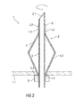
- Figure 1 is a schematic view of a medicament reservoir 1 with an exemplary embodiment of a needle unit 2.
- the medicament reservoir 1 may have a flexible reservoir wall 1.1.
- the needle unit 2 comprises a hollow needle or cannula 3 for establishing a fluid connection between the medicament reservoir 1 and a drug delivery device (not shown).
- the longitudinal extension of the cannula 3 defines an axial direction.
- the cannula 3 comprises a sharp proximal tip 3.1 intended to pierce the reservoir wall 1.1 of the medicament reservoir 1.
- the drug delivery device may comprise a medicament pump (not shown) for pumping a medicament from the medicament reservoir 1 through the cannula 3.
- the needle unit 2 comprises a sleeve 4 disposed on a section of the cannula 3. In an initial state as shown in figure 1 , the fluid sleeve 4 is substantially concentrically arranged with respect to the cannula 3.
- the needle unit 2 further comprises a stop member 5 which is axially fixed to the cannula 3 but rotatable relative to the cannula 3.
- the purpose of the stop member 5 is to limit movement of the needle unit 2 towards the medicament reservoir 1 when being attached to it.
- the stop member 5 may have a cylindrical form or any other form.
- a surface 5.1 of the stop member 5 facing the proximal tip 3.1 is shaped to allow for sealing the needle unit 2 against an outer surface of the reservoir wall 1.1 when the stop 5 is pushed against the reservoir wall 1.1.
- the sleeve 4 comprises a ring shaped proximal section 4.1 and a ring shaped distal section 4.2 adjacent the stop member 5 and a folding section 4.3 between the proximal section 4.1 and the distal section 4.2, wherein the folding section 4.3 comprises a number of longitudinal stretchers separated by longitudinal slots (not illustrated in figure 1 , cf. fig. 6 ).
- the stretchers may comprise a pivot or a weakened area, e. g. halfway or at another point along its length, defining a bending or folding behaviour of the folding section 4.3 when the proximal section 4.1 and distal section 4.2 are moved towards each other.
- Similar pivots or weakened areas may be provided for connecting the stretchers to the proximal section 4.1 and/or the distal section 4.2.
- the sleeve 4 is coupled to the stop member 5 in a manner preventing relative rotation, e.g. splined or glued.
- the stretchers of the folding section 4.3 are attached to or guided into the stop member 5 so the sleeve 4 does not have a distal section.
- the sleeve 4 comprises or consists of steel, e.g. the same steel as the cannula 3.
- the cannula 3 may comprise a tapering section 6 at the proximal tip 3.1, the tapering section 6 adapted to smoothen a transition between an external diameter of the proximal tip 3.1 of the cannula 3 and an external diameter of the sleeve 4, i.e. the proximal section 4.1, which is slightly greater than that of the proximal tip 3.1.
- the tapering section 6 may be arranged on the sleeve 4.
- the cannula 3 near the proximal tip 3.1 comprises an external thread 3.2 adapted to threadedly engage an internal thread 4.4 within the proximal section 4.1 of the sleeve 4.
- the stop member 5 may be arranged as a gap ring preventing liquid from flowing between the stop member 5 and the cannula 3.
- the needle unit 2 is partially deployed, i.e. the cannula 3 is inserted in the medicament reservoir 1 through the reservoir wall 1.1.
- the sharp proximal tip 3.1 of the cannula 3 pierces the reservoir wall 1.1 when pushed against it.
- the cannula 3 is inserted into the medicament reservoir 1 to the point where the stop member 5 abuts the outer surface of the reservoir wall 1.1. Subsequently, the cannula 3 is rotated relative to the stop member 5 and hence relative to the sleeve 4.
- the proximal section 4.1 of the sleeve 4 moves towards the stop member 5 thereby opening up and deploying the folding section 4.3 similar to an umbrella or an expansion anchor.
- Figure 2 is a schematic view of the medicament reservoir 1 with the needle unit 2, wherein the folding section 4.3 is opened up and deployed to a point where it forms a second stop inside the medicament reservoir 1 for limiting movement of the needle unit 2 in the axial direction out of the medicament reservoir 1.
- the reservoir wall 1.1 is thus squeezed between the stop member 5 and the folding section 4.3.
- FIG. 3 is a schematic view of another exemplary embodiment of a needle unit 2 prior to use.
- the needle unit 2 comprises a hollow needle or cannula 3 for establishing a fluid connection between a medicament reservoir and a drug delivery device (not shown).
- the longitudinal extension of the cannula 3 defines an axial direction.
- the cannula 3 comprises a sharp proximal tip 3.1 intended to pierce a reservoir wall of a medicament reservoir.
- the drug delivery device may comprise a medicament pump (not shown) for pumping a medicament from the medicament reservoir through the cannula 3.
- the needle unit 2 comprises a sleeve 4 disposed on a section of the cannula 3. In an initial state as shown in figure 3 , the sleeve 4 is substantially concentrically arranged with respect to the cannula 3.
- the needle unit 2 further comprises a stop member 5 which is axially fixed to the cannula 3 but rotatable relative to the cannula 3.
- the purpose of the stop member 5 is to limit movement of the needle unit 2 towards the medicament reservoir when being attached to it.
- the stop member 5 may have a cylindrical form or any other form.
- a surface 5.1 of the stop member 5 facing the proximal tip 3.1 is shaped to allow for sealing the needle unit 2 against an outer surface of the reservoir wall when the stop 5 is pushed against the reservoir wall.
- the sleeve 4 comprises a proximal section 4.1 having an internal thread 4.4 adapted to engage an external thread 3.2 of the cannula 3.
- the sleeve 4 furthermore comprises a folding section 4.3 adjacent the stop member 5, the folding section 4.3 arranged to expand radially outwards when being compressed axially in a similar way as a blind rivet. This may be achieved by the folding section 4.3 having a reduced wall thickness compared to the proximal section 4.1.
- the sleeve 4 is coupled to the stop member 5 in a manner preventing relative rotation, e.g. by splining or gluing.
- the sleeve 4 comprises or consists of a plastic material.
- the sleeve 4 comprises or consists of a bio compatible and/or drug compatible material which does not react with the medicament held in the medicament reservoir 1.
- the sleeve 4 may be made from the same material as that used for peripheral venous catheters.
- this material may be polytetrafluoroethylene or polyurethane.
- the sleeve 4 may comprise a tapering section 6 at the proximal section 4.1, the tapering section 6 adapted to smoothen a transition between an external diameter of the proximal tip 3.1 of the cannula 3 and an external diameter of the proximal section 4.1, which is slightly greater than that of the proximal tip 3.1.
- the tapering section 6 may be arranged on the cannula 3.
- the stop member 5 may be arranged as a gap ring preventing liquid from flowing between the stop member 5 and the cannula 3.
- Figure 4 is a schematic view of a medicament reservoir 1 with the needle unit 2, wherein the cannula 3 is inserted in the medicament reservoir 1 through the reservoir wall 1.1.
- the sharp proximal tip 3.1 of the cannula 3 pierces the reservoir wall 1.1 when pushed against it.
- the cannula 3 is inserted into the medicament reservoir 1 to the point where the stop member 5 abuts the outer surface of the reservoir wall 1.1. Subsequently, the cannula 3 is rotated relative to the stop member 5 and hence relative to the sleeve 4.
- the proximal section 4.1 of the sleeve 4 moves towards the stop member 5 thereby opening up and deploying the folding section 4.3 to a point where it forms a second stop inside the medicament reservoir 1 for limiting movement of the needle unit 2 in the axial direction out of the medicament reservoir 1.
- the reservoir wall 1.1 is thus squeezed between the stop member 5 and the folding section 4.3.
- a wall thickness and material of the folding section 4.3 may be selected to subject the folding section 4.3 only to elastic deformation, thus rendering the needle unit 2 re-usable.
- rotation between the sleeve 4 and the cannula 3 may be reversible so that the sleeve 4 can be returned into the initial flush configuration illustrated in figure 1 or figure 3 .
- sealing of the needle unit 2 within the reservoir wall 1.1 is achieved by the reservoir wall 1.1 being sufficiently compliant to form a sealing line between an outer surface of the cannula 3 and a circumference of a hole cut into the reservoir wall 1.1 upon penetration of the cannula 3.
- a pressure difference may exist between the reservoir 1 and the environment such that the pressure within the medicament reservoir 1 is lower than in the environment due to suction of a pump of a drug delivery device. This pressure difference may also contribute to avoiding leakage.
- Figure 5 is a schematic detail view of the needle unit 2 and the medicament reservoir 1 of figure 4 with the expanded folding section 4.3. It can be seen that the expanded folding section 4.3 forms a sealing area 11 to ensure that the medicament inside the medicament reservoir 1 leaves the medicament reservoir 1 only through the hollow cannula 3 and does not leak out of the medicament reservoir 1 outside of the cannula 3.
- the reservoir wall 1.1 is squeezed between the folding section 4.3 and the surface 5.1 of the stop member 5 such that liquid cannot escape from the medicament reservoir 1 unless being drawn through the lumen within the cannula 3.
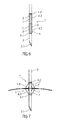
- Figure 6 is a schematic view of yet another exemplary embodiment of a needle unit 2.
- Figure 7 shows the needle unit 2 inserted into a medicament reservoir 1.
- This embodiment is similar to the one of figures 1 and 2 but comprises a stop member 5 in the shape of a second folding section 4.3', so the reservoir wall 1.1 is squeezed between the two folding sections 4.3, 4.3'.
- the sleeve 4 comprises a ring shaped proximal section 4.1 and a ring shaped distal section 4.2, wherein the folding section 4.3 is arranged adjacent the proximal section 4.1 and the second folding section 4.3' is arranged adjacent the distal section 4.2.
- Both folding sections 4.3, 4.3' respectively comprise a number of stretchers 7 separated by longitudinal slots 8.
- the stretchers 7 may comprise a pivot or a weakened area, e. g. halfway or at another point along its length, defining a bending or folding behaviour of the folding section 4.3, 4.3' when the proximal section 4.1 and distal section 4.2 are moved towards each other.
- Similar pivots or weakened areas may be provided for connecting the stretchers 7 to the proximal section 4.1 and/or the distal section 4.2.
- Both the proximal section 4.1 and the distal section 4.2 have internal threads 4.4 adapted to engage respective external threads 3.2 on the cannula 3, wherein the internal thread 4.4 in the proximal section 4.1 and the corresponding external thread 3.2 on the cannula 3 has the opposite handedness of the internal thread 4.4 in the distal section 4.2 and the corresponding external thread 3.2 on the cannula 3.
- the cannula 3 comprises or consists of steel.
- the stop member 5 may comprise or consist of a resilient rubber material or latex that is capable of forming a sealing surface and capable of forming a mechanical stop for limiting the extent of the cannula 3 penetrating into the medicament reservoir 1.
- the needle unit 2 may be reusable.
- drug or “medicament”, as used herein, means a pharmaceutical formulation containing at least one pharmaceutically active compound, wherein in one embodiment the pharmaceutically active compound has a molecular weight up to 1500 Da and/or is a peptide, a proteine, a polysaccharide, a vaccine, a DNA, a RNA, an enzyme, an antibody or a fragment thereof, a hormone or an oligonucleotide, or a mixture of the above-mentioned pharmaceutically active compound, wherein in a further embodiment the pharmaceutically active compound is useful for the treatment and/or prophylaxis of diabetes mellitus or complications associated with diabetes mellitus such as diabetic retinopathy, thromboembolism disorders such as deep vein or pulmonary thromboembolism, acute coronary syndrome (ACS), angina, myocardial infarction, cancer, macular degeneration, inflammation, hay fever, atherosclerosis and/or rheumatoid arthritis, wherein in a further
- Insulin analogues are for example Gly(A21), Arg(B31), Arg(B32) human insulin; Lys(B3), Glu(B29) human insulin; Lys(B28), Pro(B29) human insulin; Asp(B28) human insulin; human insulin, wherein proline in position B28 is replaced by Asp, Lys, Leu, Val or Ala and wherein in position B29 Lys may be replaced by Pro; Ala(B26) human insulin; Des(B28-B30) human insulin; Des(B27) human insulin and Des(B30) human insulin.
- Insulin derivates are for example B29-N-myristoyl-des(B30) human insulin; B29-N-palmitoyl-des(B30) human insulin; B29-N-myristoyl human insulin; B29-N-palmitoyl human insulin; B28-N-myristoyl LysB28ProB29 human insulin; B28-N-palmitoyl-LysB28ProB29 human insulin; B30-N-myristoyl-ThrB29LysB30 human insulin; B30-N-palmitoyl- ThrB29LysB30 human insulin; B29-N-(N-palmitoyl-Y-glutamyl)-des(B30) human insulin; B29-N-(N-lithocholyl-Y-glutamyl)-des(B30) human insulin; B29-N-( ⁇ -carboxyheptadecanoyl)-des(B30) human insulin and B29-N-( ⁇ -carbox
- Exendin-4 for example means Exendin-4(1-39), a peptide of the sequence H-His-Gly-Glu-Gly-Thr-Phe-Thr-Ser-Asp-Leu-Ser-Lys-Gln-Met-Glu-Glu-Glu-Ala-Val-Arg-Leu-Phe-Ile-Glu-Trp-Leu-Lys-Asn-Gly-Gly-Pro-Ser-Ser-Gly-Ala-Pro-Pro-Pro-Ser-NH2.
- Exendin-4 derivatives are for example selected from the following list of compounds:
- Hormones are for example hypophysis hormones or hypothalamus hormones or regulatory active peptides and their antagonists as listed in Rote Liste, ed. 2008, Chapter 50 , such as Gonadotropine (Follitropin, Lutropin, Choriongonadotropin, Menotropin), Somatropine (Somatropin), Desmopressin, Terlipressin, Gonadorelin, Triptorelin, Leuprorelin, Buserelin, Nafarelin, Goserelin.
- Gonadotropine Follitropin, Lutropin, Choriongonadotropin, Menotropin
- Somatropine Somatropin
- Desmopressin Terlipressin
- Gonadorelin Triptorelin
- Leuprorelin Buserelin
- Nafarelin Goserelin.
- a polysaccharide is for example a glucosaminoglycane, a hyaluronic acid, a heparin, a low molecular weight heparin or an ultra low molecular weight heparin or a derivative thereof, or a sulphated, e.g. a poly-sulphated form of the above-mentioned polysaccharides, and/or a pharmaceutically acceptable salt thereof.
- An example of a pharmaceutically acceptable salt of a poly-sulphated low molecular weight heparin is enoxaparin sodium.
- Antibodies are globular plasma proteins ( ⁇ 150 kDa) that are also known as immunoglobulins which share a basic structure. As they have sugar chains added to amino acid residues, they are glycoproteins.
- the basic functional unit of each antibody is an immunoglobulin (Ig) monomer (containing only one Ig unit); secreted antibodies can also be dimeric with two Ig units as with IgA, tetrameric with four Ig units like teleost fish IgM, or pentameric with five Ig units, like mammalian IgM.
- Ig immunoglobulin
- the Ig monomer is a "Y"-shaped molecule that consists of four polypeptide chains; two identical heavy chains and two identical light chains connected by disulfide bonds between cysteine residues. Each heavy chain is about 440 amino acids long; each light chain is about 220 amino acids long. Heavy and light chains each contain intrachain disulfide bonds which stabilize their folding. Each chain is composed of structural domains called Ig domains. These domains contain about 70-110 amino acids and are classified into different categories (for example, variable or V, and constant or C) according to their size and function. They have a characteristic immunoglobulin fold in which two ⁇ sheets create a "sandwich" shape, held together by interactions between conserved cysteines and other charged amino acids.
- Ig heavy chain There are five types of mammalian Ig heavy chain denoted by ⁇ , ⁇ , ⁇ , ⁇ , and ⁇ .
- the type of heavy chain present defines the isotype of antibody; these chains are found in IgA, IgD, IgE, IgG, and IgM antibodies, respectively.
- Distinct heavy chains differ in size and composition; ⁇ and ⁇ contain approximately 450 amino acids and ⁇ approximately 500 amino acids, while ⁇ and ⁇ have approximately 550 amino acids.
- Each heavy chain has two regions, the constant region (C H ) and the variable region (V H ).
- the constant region is essentially identical in all antibodies of the same isotype, but differs in antibodies of different isotypes.
- Heavy chains ⁇ , ⁇ and ⁇ have a constant region composed of three tandem Ig domains, and a hinge region for added flexibility; heavy chains ⁇ and ⁇ have a constant region composed of four immunoglobulin domains.
- the variable region of the heavy chain differs in antibodies produced by different B cells, but is the same for all antibodies produced by a single B cell or B cell clone.
- the variable region of each heavy chain is approximately 110 amino acids long and is composed of a single Ig domain.
- a light chain has two successive domains: one constant domain (CL) and one variable domain (VL).
- CL constant domain
- VL variable domain
- the approximate length of a light chain is 211 to 217 amino acids.
- Each antibody contains two light chains that are always identical; only one type of light chain, ⁇ or ⁇ , is present per antibody in mammals.
- variable (V) regions are responsible for binding to the antigen, i.e. for its antigen specificity.
- VL variable light
- VH variable heavy chain
- CDRs Complementarity Determining Regions
- an "antibody fragment” contains at least one antigen binding fragment as defined above, and exhibits essentially the same function and specificity as the complete antibody of which the fragment is derived from.
- Limited proteolytic digestion with papain cleaves the Ig prototype into three fragments. Two identical amino terminal fragments, each containing one entire L chain and about half an H chain, are the antigen binding fragments (Fab).
- the Fc contains carbohydrates, complement-binding, and FcR-binding sites.
- F(ab')2 is divalent for antigen binding.
- the disulfide bond of F(ab')2 may be cleaved in order to obtain Fab'.
- the variable regions of the heavy and light chains can be fused together to form a single chain variable fragment (scFv).
- Pharmaceutically acceptable salts are for example acid addition salts and basic salts.
- Acid addition salts are e.g. HCl or HBr salts.
- Basic salts are e.g. salts having a cation selected from alkali or alkaline, e.g. Na+, or K+, or Ca2+, or an ammonium ion N+(R1)(R2)(R3)(R4), wherein R1 to R4 independently of each other mean: hydrogen, an optionally substituted C1-C6-alkyl group, an optionally substituted C2-C6-alkenyl group, an optionally substituted C6-C10-aryl group, or an optionally substituted C6-C10-heteroaryl group.
- solvates are for example hydrates.
Landscapes
- Health & Medical Sciences (AREA)
- Engineering & Computer Science (AREA)
- Hematology (AREA)
- Anesthesiology (AREA)
- Biomedical Technology (AREA)
- Heart & Thoracic Surgery (AREA)
- Vascular Medicine (AREA)
- Life Sciences & Earth Sciences (AREA)
- Animal Behavior & Ethology (AREA)
- General Health & Medical Sciences (AREA)
- Public Health (AREA)
- Veterinary Medicine (AREA)
- Mechanical Engineering (AREA)
- Infusion, Injection, And Reservoir Apparatuses (AREA)
Priority Applications (1)
| Application Number | Priority Date | Filing Date | Title |
|---|---|---|---|
| EP15151369.4A EP3045200A1 (fr) | 2015-01-16 | 2015-01-16 | Unité d'aiguille |
Applications Claiming Priority (1)
| Application Number | Priority Date | Filing Date | Title |
|---|---|---|---|
| EP15151369.4A EP3045200A1 (fr) | 2015-01-16 | 2015-01-16 | Unité d'aiguille |
Publications (1)
| Publication Number | Publication Date |
|---|---|
| EP3045200A1 true EP3045200A1 (fr) | 2016-07-20 |
Family
ID=52345108
Family Applications (1)
| Application Number | Title | Priority Date | Filing Date |
|---|---|---|---|
| EP15151369.4A Withdrawn EP3045200A1 (fr) | 2015-01-16 | 2015-01-16 | Unité d'aiguille |
Country Status (1)
| Country | Link |
|---|---|
| EP (1) | EP3045200A1 (fr) |
Cited By (1)
| Publication number | Priority date | Publication date | Assignee | Title |
|---|---|---|---|---|
| CN107773806A (zh) * | 2017-10-30 | 2018-03-09 | 佛山市蓝瑞欧特信息服务有限公司 | 一种防脱输液管 |
Citations (5)
| Publication number | Priority date | Publication date | Assignee | Title |
|---|---|---|---|---|
| GB830222A (en) * | 1956-11-30 | 1960-03-09 | Hausmann Ag Labor | Storage and dispensing of fluids |
| US4078699A (en) * | 1975-01-23 | 1978-03-14 | Steriflex Packaging Co. | Flexible package with fluid-pressure sealing dispenser |
| FR2593068A1 (fr) * | 1986-01-21 | 1987-07-24 | Lebiedinsky Georges | Dispositif de fixation d'une canule sur un conteneur a paroi souple. |
| US4801007A (en) * | 1985-02-07 | 1989-01-31 | John Wyeth & Brother, Limited | Teat unit |
| WO2013141137A1 (fr) * | 2012-03-23 | 2013-09-26 | 株式会社ジェイ・エム・エス | Aiguille de bouteille pourvue d'un couvercle |
-
2015
- 2015-01-16 EP EP15151369.4A patent/EP3045200A1/fr not_active Withdrawn
Patent Citations (5)
| Publication number | Priority date | Publication date | Assignee | Title |
|---|---|---|---|---|
| GB830222A (en) * | 1956-11-30 | 1960-03-09 | Hausmann Ag Labor | Storage and dispensing of fluids |
| US4078699A (en) * | 1975-01-23 | 1978-03-14 | Steriflex Packaging Co. | Flexible package with fluid-pressure sealing dispenser |
| US4801007A (en) * | 1985-02-07 | 1989-01-31 | John Wyeth & Brother, Limited | Teat unit |
| FR2593068A1 (fr) * | 1986-01-21 | 1987-07-24 | Lebiedinsky Georges | Dispositif de fixation d'une canule sur un conteneur a paroi souple. |
| WO2013141137A1 (fr) * | 2012-03-23 | 2013-09-26 | 株式会社ジェイ・エム・エス | Aiguille de bouteille pourvue d'un couvercle |
Non-Patent Citations (2)
| Title |
|---|
| "Remington's Pharmaceutical Sciences", 1985, MARK PUBLISHING COMPANY |
| "Rote Liste", 2008 |
Cited By (1)
| Publication number | Priority date | Publication date | Assignee | Title |
|---|---|---|---|---|
| CN107773806A (zh) * | 2017-10-30 | 2018-03-09 | 佛山市蓝瑞欧特信息服务有限公司 | 一种防脱输液管 |
Similar Documents
| Publication | Publication Date | Title |
|---|---|---|
| US20230158247A1 (en) | Medicament delivery device | |
| US20200261661A1 (en) | Autoinjector with an inner plunger which disengages the outer plunger to retract the syringe carrier | |
| US20190351149A1 (en) | Boot remover | |
| US20200001019A1 (en) | Injection Device | |
| EP3074069B1 (fr) | Dispositif de retrait de gaine | |
| US10471206B2 (en) | Needle interface | |
| US10463808B2 (en) | Medicament delivery device | |
| EP3045200A1 (fr) | Unité d'aiguille | |
| EP3061479A1 (fr) | Ensemble d'aiguille étanché pour un dispositif d'administration de médicament | |
| WO2016055403A1 (fr) | Unité d'aiguille | |
| US20180001019A1 (en) | Pre-filled drug cartridge with stopper partially protruding from it for facilitating priming | |
| WO2016124430A1 (fr) | Unité d'aiguille pour percer une paroi de réservoir de médicament depuis l'intérieur |
Legal Events
| Date | Code | Title | Description |
|---|---|---|---|
| PUAI | Public reference made under article 153(3) epc to a published international application that has entered the european phase |
Free format text: ORIGINAL CODE: 0009012 |
|
| AK | Designated contracting states |
Kind code of ref document: A1 Designated state(s): AL AT BE BG CH CY CZ DE DK EE ES FI FR GB GR HR HU IE IS IT LI LT LU LV MC MK MT NL NO PL PT RO RS SE SI SK SM TR |
|
| AX | Request for extension of the european patent |
Extension state: BA ME |
|
| STAA | Information on the status of an ep patent application or granted ep patent |
Free format text: STATUS: THE APPLICATION HAS BEEN WITHDRAWN |
|
| 18W | Application withdrawn |
Effective date: 20170109 |