EP3043840B1 - Injektionsvorrichtung mit einem betätigungsknopf, dessen betätigung eine drehbewegung bewirkt - Google Patents
Injektionsvorrichtung mit einem betätigungsknopf, dessen betätigung eine drehbewegung bewirkt Download PDFInfo
- Publication number
- EP3043840B1 EP3043840B1 EP13762439.1A EP13762439A EP3043840B1 EP 3043840 B1 EP3043840 B1 EP 3043840B1 EP 13762439 A EP13762439 A EP 13762439A EP 3043840 B1 EP3043840 B1 EP 3043840B1
- Authority
- EP
- European Patent Office
- Prior art keywords
- dose
- housing
- rotation
- relative
- rotary member
- Prior art date
- Legal status (The legal status is an assumption and is not a legal conclusion. Google has not performed a legal analysis and makes no representation as to the accuracy of the status listed.)
- Active
Links
Images


Classifications
-
- A—HUMAN NECESSITIES
- A61—MEDICAL OR VETERINARY SCIENCE; HYGIENE
- A61M—DEVICES FOR INTRODUCING MEDIA INTO, OR ONTO, THE BODY; DEVICES FOR TRANSDUCING BODY MEDIA OR FOR TAKING MEDIA FROM THE BODY; DEVICES FOR PRODUCING OR ENDING SLEEP OR STUPOR
- A61M5/00—Devices for bringing media into the body in a subcutaneous, intra-vascular or intramuscular way; Accessories therefor, e.g. filling or cleaning devices, arm-rests
- A61M5/178—Syringes
- A61M5/31—Details
- A61M5/315—Pistons; Piston-rods; Guiding, blocking or restricting the movement of the rod or piston; Appliances on the rod for facilitating dosing ; Dosing mechanisms
- A61M5/31533—Dosing mechanisms, i.e. setting a dose
- A61M5/31545—Setting modes for dosing
- A61M5/31548—Mechanically operated dose setting member
- A61M5/3155—Mechanically operated dose setting member by rotational movement of dose setting member, e.g. during setting or filling of a syringe
- A61M5/31551—Mechanically operated dose setting member by rotational movement of dose setting member, e.g. during setting or filling of a syringe including axial movement of dose setting member
-
- A—HUMAN NECESSITIES
- A61—MEDICAL OR VETERINARY SCIENCE; HYGIENE
- A61M—DEVICES FOR INTRODUCING MEDIA INTO, OR ONTO, THE BODY; DEVICES FOR TRANSDUCING BODY MEDIA OR FOR TAKING MEDIA FROM THE BODY; DEVICES FOR PRODUCING OR ENDING SLEEP OR STUPOR
- A61M5/00—Devices for bringing media into the body in a subcutaneous, intra-vascular or intramuscular way; Accessories therefor, e.g. filling or cleaning devices, arm-rests
- A61M5/178—Syringes
- A61M5/20—Automatic syringes, e.g. with automatically actuated piston rod, with automatic needle injection, filling automatically
-
- A—HUMAN NECESSITIES
- A61—MEDICAL OR VETERINARY SCIENCE; HYGIENE
- A61M—DEVICES FOR INTRODUCING MEDIA INTO, OR ONTO, THE BODY; DEVICES FOR TRANSDUCING BODY MEDIA OR FOR TAKING MEDIA FROM THE BODY; DEVICES FOR PRODUCING OR ENDING SLEEP OR STUPOR
- A61M5/00—Devices for bringing media into the body in a subcutaneous, intra-vascular or intramuscular way; Accessories therefor, e.g. filling or cleaning devices, arm-rests
- A61M5/178—Syringes
- A61M5/31—Details
- A61M5/315—Pistons; Piston-rods; Guiding, blocking or restricting the movement of the rod or piston; Appliances on the rod for facilitating dosing ; Dosing mechanisms
- A61M5/31533—Dosing mechanisms, i.e. setting a dose
- A61M5/31545—Setting modes for dosing
- A61M5/31548—Mechanically operated dose setting member
- A61M5/3155—Mechanically operated dose setting member by rotational movement of dose setting member, e.g. during setting or filling of a syringe
-
- A—HUMAN NECESSITIES
- A61—MEDICAL OR VETERINARY SCIENCE; HYGIENE
- A61M—DEVICES FOR INTRODUCING MEDIA INTO, OR ONTO, THE BODY; DEVICES FOR TRANSDUCING BODY MEDIA OR FOR TAKING MEDIA FROM THE BODY; DEVICES FOR PRODUCING OR ENDING SLEEP OR STUPOR
- A61M5/00—Devices for bringing media into the body in a subcutaneous, intra-vascular or intramuscular way; Accessories therefor, e.g. filling or cleaning devices, arm-rests
- A61M5/178—Syringes
- A61M5/31—Details
- A61M5/315—Pistons; Piston-rods; Guiding, blocking or restricting the movement of the rod or piston; Appliances on the rod for facilitating dosing ; Dosing mechanisms
- A61M5/31565—Administration mechanisms, i.e. constructional features, modes of administering a dose
- A61M5/31576—Constructional features or modes of drive mechanisms for piston rods
- A61M5/31583—Constructional features or modes of drive mechanisms for piston rods based on rotational translation, i.e. movement of piston rod is caused by relative rotation between the user activated actuator and the piston rod
Definitions
- the invention is in the field of injection devices for administering a liquid product, in particular a medicament, such. B. insulin for diabetes therapy.
- the invention relates to a drive device, such as. B. a drive and metering device for such an injection device.
- the drive spring is a clock spring, which is spirally wound from a band-shaped material.
- the spring is tensioned with a rotary motion.
- a piston rod of the device is coupled to the spring by actuation of an actuation button at the proximal end of the device whereby the spring can deliver the energy stored in it to the piston rod, thereby moving the piston rod in the dispensing direction.
- actuation button at the proximal end of the device
- a drive and metering device is described as shown in the attached Figures 1 to 5c is pictured.
- This device has a drive spring, which is biased in the delivery state of the drive and metering device with so much energy that they can distribute the distributable from the product container amount of product in several individual distributions.
- the ejection spring drives a rotary member, the rotation of which causes a propelling member to displace the piston of a product container, thereby dumping the product contained in the product container.
- a Push button operated whereby a closed clutch is opened, wherein the opened clutch allows the rotation of the rotary member and the closed clutch does not allow the rotation of the rotary member.
- Such injection devices require that the preloaded discharge spring without further action, the product distribution starts when the operating knob or push button is fully actuated. Since such injection devices can sometimes store up to their use, it may be that the mechanism is "solid" or does not dissolve properly when the actuator button is fully depressed, so that a product release z. B. starts delayed or only by light knocking (mechanical shaking) starts against the injection device.
- the invention relates to a drive device, in particular a drive and metering device, for an injection device for administering a liquid medicament or product.
- a drive device With the drive device, a fixed or unchangeable dose can be distributed or set a dose and then distributed. If the drive device, the setting of a, z. B. variable, dose allowed, such as. B. by twisting a tangible by the user dosing, it can also be referred to as a drive and metering device.
- the drive device has a housing.
- the housing is preferably sleeve-shaped and / or elongated.
- the housing can be z. B. extend along its longitudinal axis.
- the housing can optionally accommodate a product container or even form the product container.
- the housing can be one or more parts.
- the housing may form a proximal housing part that includes or comprises the drive device.
- the housing may further include a product container holder, which holds the product container, such. B. a carpule, receives and is connected to the housing or the proximal housing part. This connection may be such that the product container holder and the housing or the proximal housing part after connection unsolvable, d. H. only by destruction of fasteners is solvable.
- Such an embodiment is particularly advantageous in the case of disposable injection devices which, after the product contained in the product container has been completely poured out, are discarded as a whole.
- the product container holder can also be releasably secured to the housing, whereby it is possible to use the drive device, if necessary several times, d. H. replace an empty product container with a filled product container.
- the housing preferably serves to be gripped by the user of the device.
- the housing may have a substantially cylindrical shape.
- the housing may, for. B. a pointing device, in particular a window, by means of which or by which a currently set dose, preferably from a scale of a dose setting element, can be read.
- the drive device may have a propulsion member whose distal end is intended to act on a piston, in particular indirectly or preferably directly.
- the piston may be part of a device attached to the drive device or attachable product such.
- the propulsion member can be referred to in a broader sense as a piston rod, wherein the propulsion member does not necessarily have to be solid, but also hollow, such. B. can be configured sleeve-shaped.
- At the distal end of the propulsion member can optionally a z.
- B. rotatable flange which presses against the piston.
- the propulsion member is preferably displaceable relative to the housing along the longitudinal axis of the drive device.
- the drive device may comprise an abutment and preferably a guide, wherein the propulsion member relative to the abutment and preferably also relative to the guide in one direction, in particular in the distal direction, d. H. in the dispensing direction, is movable to effect a release of the product or possibly the or a set product dose.
- the propulsion member may be guided straight or axially by means of or on the guide, along the longitudinal axis of the drive device.
- the propulsion member may be non-rotatable relative to the abutment and / or the guide and / or the housing.
- the propulsion member may be rotatable relative to the abutment or housing combined with longitudinal movement, i. H.
- the guide and / or the abutment of the housing in particular a sleeve-shaped housing part or a z.
- B. sleeve-shaped, housing-fixed element are formed.
- the propulsion member and the guide formed in particular by the housing may be engaged to prevent rotation of the propulsion member relative to the abutment or the housing and to permit axial movement or screwing movement of the propulsion member relative to the abutment or housing.
- the leadership can z. B. be an axial guide or a thread with a non-self-locking thread pitch.
- the guide or the abutment or / and the guide forming housing portion may preferably surround the propulsion member, such as. B. sleeve-shaped and / or be fixed to the housing or formed by the housing. Between this sleeve-shaped housing part and an outer, preferably also sleeve-shaped housing part, an annular gap may be formed, which has the advantage that an optional dose indicator element, in particular a dose indicator drum, therein z. B. can be added movably. This causes the length of the drive device can be kept low.
- the drive device can at least one, such as. B. have exactly one, two or three acting between the driving member or a rotary member and the abutment and in particular arranged discharge spring.
- the at least one spring can be z. B. on the propulsion member and / or the abutment.
- the z. B. single discharge spring with its distal end on the driving member and with its proximal end supported on the abutment.
- the at least one discharge spring can be arranged inside the guide or the sleeve-shaped housing part forming the guide. If the advancing member is sleeve-shaped, the at least one discharge spring can be arranged within the advancing member.
- a first discharge spring and a second discharge spring may in particular be arranged kinematically between the advancing member and the guide or the sleeve-shaped housing part forming the guide.
- the second discharge spring can be arranged concentrically to the first discharge spring.
- the first discharge and the second discharge can z. B. be connected in parallel or in series.
- Shunt springs connected in parallel mean, in particular, that the first and second discharge springs can each be supported with their distal end on the advancing member and each with its proximal end on the abutment. This allows the spring constants of the first and second discharge spring to add up to a total spring constant.
- In-line distribution springs means, in particular, that the distal end of one of the first and second discharge spring presses against the proximal end of the other from the first and second discharge, in particular directly or preferably indirectly, such. B. via an intermediate member.
- the first discharge spring is supported on the abutment and the intermediate member and the second discharge spring on the intermediate member and the advancing member from.
- the distal end of the first delivery spring can be arranged distally of the proximal end of the second delivery spring. Due to the intermediate member, the spring force of the first spring can be transmitted from its distal end to the proximal end of the second discharge spring.
- the intermediate member may be sleeve-shaped and arranged in an annular gap between the first and second discharge spring. In series connected distribution springs allow, over a relatively long spring travel a relatively constant spring force.
- the at least one discharge spring in particular the first and second discharge spring may be a helical or helical spring which acts as a compression spring or as a torsion spring.
- the at least one discharge spring is biased and thus acts on the driving member, which it tries, the driving member relative to the abutment in the distal Direction, ie to move in the dump direction.
- the at least one discharge spring is biased in the delivery state of the drive and metering device, in particular with so much energy that they can distribute the maximum or total distributable from the product container amount of product, for example in several individual distributions, ie in particular in several distributions of individual product cans.
- the drive device if a dose is adjustable with it, be designed so that after each individual distribution or distribution of the product dose, the next dose to be distributed is reset.
- the drive device may comprise a dosing member which is designed, for example, as a dosing button and may optionally be referred to as dose setting member.
- dose setting member In contrast to embodiments in which a discharge spring is re-energized at each dose setting, the energy-preloaded spring required to deliver the maximum amount of product dispensed from the product container allows for easier dose adjustment because of dose adjustment relative to the housing rotatable dosing is then easier rotatable, because the spring need not be biased at the dose setting. This increases the ease of use for the user of the device.
- the drive device may further include a rotary member, the rotation of which causes the spring to deliver energy to the propelling member, thereby moving the propelling member in the distal direction.
- the rotary member preferably performs the function of a control member, wherein the rotation of the rotary member causes by a certain angle of rotation, the advance of the advancing member to a certain Aus thoroughlyhub.
- the spring may be allowed to or may not move the propelling member relative to the abutment in the distal direction.
- the rotary member may be coupled to the actuator such that upon actuation of the product dispensing actuator, it is released for rotation relative to the housing and is locked for non-actuation of the actuator for rotation relative to the housing.
- a clutch in particular Aus thoroughlykupplung be arranged, which causes the release and blocking of the rotation of the rotary member relative to the housing.
- the closed clutch can be opened by pressing, in particular pressing the actuator, wherein the open clutch releases the - caused by the prestressed spring - rotation of the rotary member, in particular discharge spring, relative to the housing releases.
- the clutch can release the rotation of the rotation member relative to the housing and, by releasing the actuator, block the rotation of the rotation member relative to the housing.
- the actuator is coupled to the rotary member such that the actuation, in particular the depression of the actuator, causes the rotary member to rotate relative to the housing already when the clutch is still closed.
- the actuator is between an unactuated, d. H. unpressed position, and an actuated position, d. H. pressed position, back and forth, in particular along the longitudinal axis of the drive device.
- the unactuated position may also be referred to as the starting position of the actuator.
- the clutch is opened when the actuator is in its actuated position.
- the actuating member is coupled to the rotary member via a gear, which converts the movement of the actuating member along the longitudinal axis L, in particular in the distal direction, into a rotational movement of the rotary member, in particular in the first rotational direction.
- the rotation of the rotary member caused by the actuation of the actuating member relative to the housing when the clutch is closed is less than 45 °, in particular less than 20 °.
- the rotation of the rotary member caused by the actuation of the actuator is directed relative to the housing in the same direction of rotation, in particular in the first direction of rotation, alternatively in the opposite direction of rotation, in particular the second direction of rotation, as the direction of rotation by means of the prestressed spring effected rotation of the rotary member.
- the effected by means of the prestressed spring rotation of the rotary member takes place in the first direction of rotation.
- the actuator may be coupled to the rotary member such that the return movement of the actuator from its actuated positions to its unactuated position, particularly the release of the actuator, causes the rotary member to rotate relative to the housing in one direction, particularly the second, d. H. the first direction of rotation opposite direction rotates, which is opposite to the direction of rotation, in particular the first direction of rotation, which can be effected by means of the prestressed spring rotation.
- the actuator can be moved back from its actuated position to its unactuated position by a spring, in particular a reset or clutch spring, which is biased by the actuation of the actuator. This spring can thereby rotate the rotary member, in particular via the transmission, in the second direction of rotation.
- the product container piston move in the first direction of rotation upon product dispensing or rotation of the rotary member acting on him in the direction of ejection propulsion member is moved in the delivery direction and that when moving back the actuator in its unactuated position, the advancing member is moved against the dispensing direction relative to the abutment, in particular so far that the piston is relieved of the pressure of the advancing member.
- the rotation of the rotary member in the second direction of rotation causes the propelling member to be moved at least a very small distance in the proximal direction, ie counter to the dispensing direction, so that the piston of the product container is relieved.
- the discharge spring can be slightly tensioned again.
- the clutch is already closed when the propelling member moves in the proximal direction.
- the above-mentioned transmission may include a first transmission element and a second transmission element.
- a first part may form the first gear element and a second part the second gear element, wherein the first gear element slide off the second gear element by the actuation of the actuator, whereby the actuation, in particular the pressing of the actuator causes the rotational member relative to the housing already then, in particular in the first direction of rotation, rotates when the clutch is still closed.
- the housing or a housing-fixed element may be the first part and a clutch-forming, for example, sleeve-shaped displacement member, in particular a bearing element which is at least axially displaceable with respect to the housing or the housing-fixed element, the second part.
- the sliding member can surround the housing-fixed element.
- the first part and the second part can engage in such a way that a displacement of the second part effected by actuation of the actuating element causes a rotation of the second part relative to the first part.
- one of the first part and the second part may comprise an engagement member, the other of the first and second parts having a guideway, wherein movement of the engagement member in the guideway causes rotation of the second part relative to the first part.
- the guideway may be a thread or a threaded portion.
- the guideway may have a proximal and / or a distal guideway section, which are connected to one another via a transition section or wherein a transition section adjoins the proximal or distal guideway section.
- the engagement member when moved in the guideway, in particular in or through the transition section, causes rotation of the second part relative to the first part, in particular in the first direction of rotation when the actuator is actuated and the engagement member into a first Direction in the guideway or moved through or in the transition section, and in particular in the second direction of rotation when the actuator is released and the engagement member in a second direction, which is opposite to the first direction, in the guideway or by or in the Transition section moves.
- proximal guideway portion and / or the distal guideway portion may be parallel to the longitudinal axis such that the second portion is relative to the second guideway portion first part is rotationally fixed and axially displaceable when the engaging member is located in the proximal or distal guideway portion.
- the rotary member forming the coupling can be the second part and a sliding member forming the coupling, in particular the bearing element which is rotationally fixed relative to the housing or a housing-fixed element and displaceable along the longitudinal axis of the drive device.
- the first part and the second part may slide against each other, whereby the first part is rotated relative to the housing, in particular in the first direction of rotation Actuator is actuated, and / or in the second direction of rotation when the actuator is released.
- the first part and the second part can intermesh.
- the first part may have projections which face towards the second part, wherein the second part may have projections pointing towards the first part.
- the mutually facing and interlocking Abragonne can slide off each other when the actuator is actuated.
- the Abragonne can for example be part of the coupling structure of the said coupling, wherein the coupling is not released until the preferably mutually facing Abragungen slid together and out of engagement.
- the rotary member can rotate relative to the housing and the second part by means of the biased discharge spring in the first direction of rotation.
- the rotary member may be a toothing or a plurality of arranged over its circumference, for. B. sawtooth-shaped, teeth in which a locking cam, which is formed by an over the circumference of the rotary member arranged intermediate sleeve, resiliently engages, wherein the intermediate sleeve is the first part and forms a coupling structure of the coupling and a displacement member, in particular a bearing element, which is non-rotatable and axially displaceable with respect to the housing or a housing-fixed element, the second part, wherein the preferably sleeve-shaped displacement member surrounds the intermediate sleeve over its circumference.
- the intermediate sleeve can be arranged concentrically between the rotary member and the displacement member.
- one of displacement member and intermediate sleeve may have a Abragung, which in a guideway of the other Sliding member and intermediate sleeve engages.
- the guideway may be a thread or a threaded portion.
- the guideway may have a proximal and / or a distal guideway section, which are connected to one another via a transition section or wherein a transition section adjoins the proximal or distal guideway section.
- the Abragung when moved in the guideway, in particular in the transition section, causes a rotation of the intermediate sleeve and in particular of the rotary member relative to the sliding member, in particular in the first rotational direction when the actuator is actuated and the Abragung in a first direction in the guide track, in particular moved by or in the transition section, and in particular in the second direction of rotation when the actuator is released and the projection in a second direction, which is opposite to the first direction, in the guideway, in particular by or in the transition section moves.
- the proximal guideway section and / or the distal guideway section may be parallel to the longitudinal axis such that the intermediate sleeve is rotationally fixed and axially displaceable relative to the sliding member when the protrusion is in the proximal or distal guideway section.
- the engagement of the detent cam in the circumferentially disposed teeth is such that rotation of the intermediate sleeve relative to the rotary member in the first rotational direction is prevented and rotation of the rotary member relative to the intermediate sleeve in the first rotational direction is possible.
- the actuation of the actuator causes a rotation of the intermediate sleeve in the first direction of rotation relative to the housing, wherein the intermediate sleeve entrains the rotary member, that rotates.
- the drive spring may rotate the rotary member relative to the intermediate sleeve in the first direction of rotation since the clutch is open.
- the coupling member in particular the bearing element or its inner surface, such.
- the locking cam prevent it from being moved out of the teeth of the rotary member when the actuator is not operated or not completely operated, that is not in its actuated position.
- the displacement member in particular the bearing element releases a movement of the latching cam from the toothing, when the actuating member is fully actuated, that is, in its actuated position.
- the displacement member may for this purpose have a recess which is pushed by means of actuation of the actuating element via the latching cam, so that the latching cam can move out of engagement with the toothing.
- the inner surface of the displacement member, in particular of the bearing element, from the position in which it holds the latching cam in engagement with the toothing are moved, so that the latching cam can move out of engagement with the toothing.
- the locking cam moves with a movement in approximately radially outward, ie away from the longitudinal axis, from engagement with the toothing and with a movement in approximately radially inwardly, ie to the longitudinal axis, in the toothing.
- the discharge spring is arranged kinematically between the piston of the product container and the rotary member.
- the ejection energy provided by the discharge spring has to run for the most part on the rotary member, as it is z.
- the rotary member would be arranged kinematically between the discharge and the piston.
- the rotary member can be made simpler.
- the at least one discharge spring drives the propulsion member and the propulsion member drives the rotation member.
- the propulsion member can be arranged kinematically between the discharge spring and the rotary member.
- the angle of rotation of the rotary member may be proportional to the delivery stroke of the piston or of the advancing member. This can be achieved by the selective blocking or release of the rotary member.
- the rotary member can be in engagement, in particular a threaded engagement with the advancing member.
- the thread pitch of this thread engagement is achieved that z. B. in a complete revolution of the rotary member relative to the housing, the driving member of the discharge spring is displaceable by a stroke corresponding to the thread pitch.
- the rotary member may include or be a threaded rod and the propelling member may be a threaded nut, with the thread of the threaded nut engaging the threads of the threaded rod.
- the rotary member may include or be a threaded nut and the male member may be a threaded rod, with the thread of the threaded nut engaging the threads of the threaded rod.
- the rotary member is axially fixed with respect to the housing or at least in one, preferably in the distal direction axially fixed to the housing or a housing-fixed element, such as. B. support the abutment.
- the rotational member during setting a dose, d. H. in the unactuated state in particular by means of the coupling, rotatably connected to the housing and is rotated during operation of the device for dispensing the product dose relative to the housing or is rotatable.
- the drive and metering device has a dose indicator element, in particular a dose indicator drum.
- the dose indicating element may, for example, be in threaded engagement with the housing or a housing fixed member, whereby the dose indicating element is screwable to the housing by rotating a dose setting member.
- the dose indicator element may be in threaded engagement with the sliding member, in particular the bearing element.
- the dose indicating element in particular the dose indicating drum, can be rotatable relative to the rotating member during the setting of a dose, ie in the unactuated state of the drive and metering device or of the actuating member.
- the dose indicating element is non-rotatable and e.g. B. axially movable, or rotationally fixed connected to the rotary member, in particular with the described coupling or another coupling.
- the dispensing spring returns the dose indicator to its zero dose position, particularly via the rotary member and preferably via a coupling member which is preferably rotationally fixed but axially displaceable with respect to the dose indicator.
- the coupling member and the dose indicating element may be in a rotationally fixed engagement allowing axial movement between the dose indicating element and the coupling member.
- This intervention can z. B. be effected by means of a longitudinal guide.
- the coupling member is axially fixed but rotatably connected to the displacement member, in particular the bearing element.
- the drive and metering device may have a first coupling structure, which is rotationally fixed with respect to the housing.
- the rotary member may include or form a second coupling structure which, in coupling engagement with the first coupling structure, causes the rotary member to be rotationally fixed with respect to the housing.
- the first coupling structure may, for. B. from the housing or a rotationally fixed with respect to the housing but axially displaceable sliding member, such. B. be formed the bearing element.
- the coupling member may have a third coupling structure which, in engagement with the first coupling structure or a further, fourth coupling structure of the rotary member, causes the dose indicator to be non-rotatably connected to the rotary member.
- the actuator When the actuator is in its unactuated position, the rotary member and the housing are rotationally fixed with respect to each other, in particular the first and the second coupling structure in engagement, wherein the third and second or optionally the third and fourth coupling structure are free of engagement.
- the actuator is in its actuated position, the third and second, optionally third and fourth, coupling structures are engaged with the first and second coupling structures preferably disengaged from each other.
- the dose indicator is already rotatably coupled to the rotary member and the rotary member is still rotatably connected to the housing, while the actuating member is displaced for the actuation with respect to the housing is particularly advantageous.
- the first and the second and the third and the second, optionally the third and the fourth coupling structure may be simultaneously in engagement, namely, when the actuator occupies its intermediate position.
- the dose indicator may include a stop, such as a stopper.
- a stop such as a stopper.
- B a zero dose stop, which is moved away from a counter stop, in particular a zero dose counter-stop when a dose increase is made, and which is moved to the counter-stop when a dose reduction is made, or when the device is actuated for the distribution of the set product dose.
- the dose indicator may be adjusted during adjustment of the product dose, i. H. upon dose increase and dose reduction, be at least rotationally decoupled from the rotary member and be coupled to the rotary member upon actuation of the product dose dispensing device such that rotation of the rotary member causes the dose indicator to engage the counter stop, i. H. the zero dose stop is moved towards the zero dose counter stop. If the zero dose stop and the zero dose counter stop in a stop or a contact, thereby and in particular via the coupling, rotation of the rotary member and thus further advancement of the driving member is prevented relative to the housing.
- a Dosierkupplung can be provided between the dosage setting member and the dose indicating element, which rotatably fixes the dose setting member with the dose indicating element coupled when the drive and metering device or the actuator is unconfirmed, and rotatably decoupled when the drive and metering device or the actuator is actuated.
- the dose indicating element and the dosing member are non-rotatably connected via the metering coupling when the actuator is unactuated and the dose indicating member is rotatable relative to the dose setting member when the actuator is actuated.
- the drive and metering device may have a mechanism for preventing the setting of a dose exceeding the amount of a drug in the product container.
- this mechanism may block the rotation of the dosing member in a direction that would cause a dose increase, especially when the maximum dose stop of the dose indicator and the maximum dose counterpart stop are not yet engaged or, for example, a smaller dose is indicated in a pointing device as the maximum adjustable product dose.
- the mechanism thus prevents a dose which exceeds the residual amount of product contained in the product container from being set, thereby reducing the risk of misuse of the drive and metering device.
- the mechanism may, for.
- Example have a limiter, which is mounted between two parts, one of which rotates relative to the other during the dose setting and does not rotate during the operation, ie the dose distribution.
- the limiter may be arranged between the dosage setting member, which may be configured in particular as dose setting knob or dose setting sleeve, and the housing or a housing-fixed element.
- the restrictor, dose setting member and housing may be coupled together such that relative rotation, particularly during dose adjustment, between the dose setting member and the housing causes the restrictor to move to a stop position in which the restrictor prevents setting of a dose that exceeds the amount of a product in the product container.
- the limiter may have an internal thread which is in engagement with an external thread of the housing.
- the limiter on its outside a Longitudinal guide, with which it is in engagement with the dose setting, so that the dose setting member is rotatable relative to the limiter.
- the housing may have the longitudinal guide for the limiter, so that the limiter is rotationally fixed relative to the housing and the limiter may have a thread, in particular external thread, which engages in a thread, in particular internal thread of the dose setting.
- the stop position is defined by a stop for the limiter, wherein the stop can be formed by the housing or dose setting member or an at least axially or circumferentially fixed housing means. If the limiter and the stop are in contact, rotation of the dosage setting member in a direction of rotation which would cause an increase in the dose is no longer possible or blocked.
- the drive and metering device may optionally have at least one signal generation mechanism which is adapted to generate an acoustic and / or tactile signal, in particular mechanically, during the dose setting and / or product dispensing.
- a signal can be perceived in particular as a click signal.
- a (first) signal generation mechanism may be provided which generates the signal during dose setting and may optionally be referred to as a dose adjustment signal generation mechanism.
- a (second) signal generation mechanism may be provided which generates the signal during product dispensing and may optionally be referred to as a product dispensing signal generation mechanism.
- a (common) signal generation mechanism may be provided which generates the signal during dose setting and during product dispensing.
- the signal generation mechanism may generally be arranged between two parts that move relative to each other in the dose setting and / or the product distribution, in particular rotate.
- One of the parts can be a z. B. resiliently arranged locking member, which in a z. B. engages over the circumference arranged toothing of the other of the two parts. If a part is rotated relative to the other, the locking member can slide over the teeth and thereby generate the signal.
- the toothing may be formed by an inner circumference or an outer circumference or an end face of the part.
- the product delivery signal generation mechanism may be formed by the intermediate sleeve cam described above in connection with one embodiment.
- the signal generation mechanism can be formed in particular between coupling member and sliding member or bearing element.
- the coupling member and the sliding member or bearing member rotate relative to one another during dose setting and product dispensing, thereby forming a signal generating mechanism that generates the signal during dose setting and product dispensing.
- the signal generation mechanism can be formed, in particular, between displacement element or bearing element and rotation element, wherein the design of the displacement element or bearing element, at least in this context, also applies to a switching sleeve described herein.
- the sliding member or bearing member and the rotary member rotate while, particularly during product dispensing relative to each other, thereby forming a signal generating mechanism that generates the signal during product dispensing.
- the signal generation mechanism may in particular be formed between the coupling member and the rotary member.
- the coupling member and the rotary member rotate while, in particular, only during the dose setting relative to each other, thereby forming a signal generating mechanism which generates the signal during dose setting.
- a dose scale can be arranged over the circumference of the dose indicator element.
- the dose indicator may e.g. B. be annular in cross section.
- the dose indicator may e.g. A dose indicator drum or dose indicator ring.
- the dose scale may extend over the circumference of the dose indicator element, preferably helically.
- the dose scale preferably comprises a plurality of values arranged in a row and giving the dose scale. Preferably, these are numerical values which indicate the desired product dose in international units (IU).
- the dose scale without slope over the circumference of the dose indicator element such as.
- the dose indicator ring be arranged, with the scale values then repeat after a rotation of the dose indicator element.
- the dose indicator in particular the dose display drum, with more than one revolution can be rotated without repeating the scale values, which can advantageously the scale values greater or more scale values can be displayed.
- the drive and metering device further comprises a pointing device, wherein the dose indicator element for adjusting the dose to be administered relative to the pointing device and in particular about an axis of rotation, which preferably corresponds to the longitudinal axis of the drive and metering device and / or the dose indicator element, is rotatable.
- This may be a pure rotational movement, d. H. to act a rotary motion without superimposed axial movement.
- the rotational movement is superimposed on an axial movement, whereby the dose indicator element for adjusting the dose to be administered can be screwed relative to the pointing device.
- a screwable dose indicator can be advantageously combined with a helical dose scale, wherein the screwing and the dose scale advantageously have the same slope.
- a dose display element rotatable without axial movement can advantageously be combined with a gradient-free dose scale.
- a value of the dose scale is read, which corresponds to the set dose.
- the pointing device can, for. B. may be a window that may be formed by a breakthrough in the housing or by a transparent insert.
- the pointing device can be an arrow or have an arrow, the z. B. in addition to the window marked the value of the dose scale, which corresponds to the set dose. This is z. B. advantageous if in the window still another value appears at least partially, to ensure a clear dose selection.
- the pointer can z. B. a projection or a print or a notch or the like.
- the dosing member is preferably greibar by the user (patient, doctor, medical auxiliaries) of the drive and metering device and preferably forms an outer, in particular accessible from the outside surface of the drive and metering device.
- the dosing member is preferably gripped by the user and relative to the housing and in particular the pointing device about an axis of rotation, preferably the longitudinal axis of the z.
- B. elongated drive and metering device corresponds, twisted.
- the dosing member is preferably axially fixed to the housing, in particular displaceable along a longitudinal axis of the housing, thereby advantageously facilitating the intuitive handling of the device by the user, since he only needs to perform a rotational movement of the dosing for dose adjustment.
- the dose indicator element at least during the dose setting rotationally, but z. B. axially slidably connected to the dosing or coupled.
- the dose indicator element is also rotated by a rotation angle about this rotation angle when the dosing member is rotated.
- the preferably designed as an actuating button actuator may form an outer surface of the drive device and / or be accessible from the outside.
- the actuator may be formed at the proximal, in particular rear end of the drive device or form this end.
- the actuator can be advantageously in this way with the thumb of the hand, which presses the housing surround press in particular. By releasing the actuator, the operation can be terminated.
- the actuator can advantageously against the force of a spring, in particular a reset or clutch spring slidably, in particular be actuated, whereby this spring is tensioned. By releasing this spring can reset the actuator, in particular relative to the dosing, in particular in the proximal direction or out of the drive device move.
- the drive and metering device may further comprise a bearing member with which the dose indicator is engaged.
- This intervention advantageously causes the Rotary or screwing movement of the dose indicating element relative to the pointing device.
- the engagement between dose indicator element and displacement element, in particular bearing element can be a threaded engagement.
- the bearing element can have an external thread and the dose indicator element an internal thread, wherein these threads mesh with each other and thereby cause the dose indicator element to be screwed relative to the bearing element.
- the dose indicator element is rotatable or screwable between a maximum dose position and a zero dose position.
- the zero dose position advantageously, the dose or digit "0" in the pointing device can be read.
- the maximum dose position the maximum product dose that can be distributed with the drive and metering device can be read.
- the dose indicating element may be locked against rotation in one direction of rotation, namely the direction of rotation that would cause a dose to be set less than zero.
- the dose indicator may preferably be moved only in the direction of rotation which causes an increase in the dose.
- the dose indicator is preferably blocked against rotation in one direction of rotation, namely the direction of rotation that would cause the setting of a dose beyond the maximum adjustable dose.
- the dose indicator element can be rotated in the maximum dose position, in particular only in the direction of rotation, which causes a reduction in the product dose.
- the dose indicator may e.g. B. have a stop which abuts in the zero dose position to a counter-stop and thus prevents rotation in one direction.
- the same or an additional stop of the dose indicating element may prevent the rotation of the dose indicating element beyond the maximum dose.
- a further counter-stop namely a maximum dose counter-attack can be provided.
- the other counterstop may be referred to as a zero dose counterstop.
- the dose indicator may include a zero dose stop for the zero dose counter-stroke and a maximum dose limit stop for the maximum dose counter-stroke exhibit.
- the stop or the stops act in the circumferential direction and / or in the axial direction.
- the bearing element can be displaceable relative to the housing and along the axis of rotation, in particular in the distal direction, together with the dose indicator element.
- the dose indicating element may have a thread which is engaged with the housing.
- the actuator is coupled to the bearing member such that displacement of the actuator relative to the housing and / or dose setting member displaces the bearing member relative to the housing and / or dosage setting member, particularly along the longitudinal axis of the drive or drive and metering device causes.
- the dose indicator is in engagement with the bearing element and the bearing element can be moved relative to the housing and along the axis of rotation, and the dose indicator is relative to the housing and along the axis of rotation regardless of the rotational or screwing movement, which the dose indicator at the dose setting, move.
- the drive and metering device can basically also be advantageously combined with the alternative dose indicator element which is in threaded engagement with the housing or a housing-fixed element.
- the bearing element may be formed by the housing or be part of the housing, wherein the bearing element then z. B. can be rotationally and axially fixed with respect to the rest of the housing.
- the sliding member and the bearing element are then separate parts, for example.
- the bearing element has been displaced together with the dose indicator element.
- the user can check in which operating state the drive and metering device is located, ie whether the drive and metering device, in particular the actuation element, is actuated or unconfirmed for a discharge.
- the actuating member and / or the bearing element can be displaceable together with the dose indicator element relative to the pointing device, the housing and along the axis of rotation.
- a mark different from the dose scale may appear when the bearing element is displaced.
- the marker is preferably arranged on the dose indicator. If the bearing element is unshifted, in particular the drive and metering device for the product distribution is unconfirmed, the marking can be arranged outside of the pointing device, such. B. be covered by a housing or other element.
- the marking can emerge from the covered area, so that it appears or can be read, in particular, on or in the pointing device. If the operation of the drive and metering device is interrupted or terminated, the bearing element can return to the original position, whereby the marking is preferably removed from the area of the pointing device and in particular concealed.
- the actuator or / and the bearing element may be displaceable relative to the housing and along the axis of rotation together with the dose indicator element and the pointing device.
- the pointing device can, for. B. be a panel or at least fulfill the function of a panel.
- the pointing device may be at least axially fixed, preferably also non-rotatably connected to the bearing element.
- the bearing element can form the pointing device.
- the pointing device is a separate part from the bearing element.
- the pointing device can, for. B. be sleeve-shaped.
- the displacement of the bearing element can cause that in the area of the pointing device a different mark from the dose scale appears, which is arranged or formed on or on the pointing device.
- the pointing device can be arranged inside the housing.
- the marking of the pointing device can be hidden in the unactuated state of the drive and metering device of the housing or other element. If the drive and metering device, in particular the Actuator, actuated so that the dose indicator is moved together with the pointing device, the label can emerge from its cover, so that the label is visible or readable. If the operation is interrupted or terminated, the dose indicator can be moved back together with the pointing device and the bearing element to its original position, so that the mark is again arranged under the cover.
- a spring in particular a clutch or return spring can be clamped.
- the bearing element can be moved during the operation against the force of a particular such spring, in particular from an unactuated position to an actuated position.
- the spring can z. B. be a helical or spiral spring, which acts as a compression spring.
- This spring also causes the bearing element to be reset to its initial or unactuated position when the operation is interrupted or terminated.
- the bearing element is displaced in the distal direction during actuation.
- the bearing element is moved back in the proximal direction when the operation is interrupted or terminated.
- the actuation of the actuator in particular causes the bearing element is displaced together with the dose indicator element relative to the housing and along the axis of rotation.
- the actuator is preferably connected to the displacement member, in particular the bearing element so that it displaces the displacement member when actuated, in particular via a coupling member, the z. B. axially fixed and can be rotatably connected to the sliding member.
- actuation of the actuator may cause the dose indicator to be rotated, in particular screwed, relative to or on the bearing member or housing, particularly in a direction that counters the values of the dose scale moving past the pointing device as it rotates.
- the angle of rotation of the dose indicator element and the Dispensing stroke of the advancing member in a proportional relationship, in particular at any time during the dose distribution. This allows a real-time display to be made which counts back to the dose distribution until it finally reaches 0, with the distribution of that dose then being completed. If the dispensing operation is interrupted while the dose indicator is being turned back, the dose indicator will indicate the remaining amount still required to dispense that dose.
- the drive and metering device can be configured such that the energy required for turning back the dose indicator element and / or displacing the advancing member in the distal direction is stored automatically, in particular by a spring, in particular a discharge spring, in which the required energy is stored is or can be provided.
- a spring in particular a discharge spring, in which the required energy is stored is or can be provided.
- the spring energy stored in the dispenser spring may be delivered to the dose indicator or / and propulsive member such that the dose indicator is rotated backward and the advancer member is displaced distally.
- the spring can already be biased at delivery of the drive and metering device with so much energy that the energy is sufficient for several distributions of the product dose, in particular sufficient for the distribution of the whole ausurgibaren from the product container product.
- the dosing member may be decoupled from the spring at the dose setting, i. H. not be coupled to the discharge spring so that rotation of the dosing member causes a tensioning of the spring. This allows the dosing member for the user in the dose setting rotate with significantly less force.
- the dosing in particular the Dosierknopf can surround the actuator, in particular the actuating button or record.
- the dosing member and the actuator may form the proximal end of the drive and metering device.
- the actuating member for the actuation is displaceable relative to the dosing member.
- the dosing member may be arranged to be axially fixed and rotatable relative to, in particular on the housing.
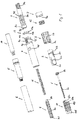
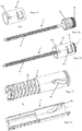
- a drive and metering device in which the invention can be advantageously used or integrated, can, as for example from the FIGS. 1 and 2a to 2c can be seen, a sleeve-shaped housing 4, which has an outer sleeve 4b, which is encompassed by the user with one hand.
- the housing 4 further comprises an inner sleeve 4a, which forms an abutment 4i and is arranged concentrically to the outer sleeve 4b.
- Inner sleeve 4a and outer sleeve 4b are interconnected via an annular web.
- a dose indicator 10 which is designed in particular as a dose indicating drum, ie sleeve-shaped, a bearing element 9 and a coupling member 2, which is sleeve-shaped and can also be referred to as a display coupling arranged are.
- a sleeve-shaped product container receptacle 5 made of a preferably transparent material is arranged, in which a product container 14 is received in the form of a carpule.
- the product container 14 is permanently connected by means of the product container receptacle 5 to the housing 4, so that the drive and metering device forms a disposable injection device, in particular together with the product container receptacle 5 and the product container 14, which is disposed of as a whole after complete emptying of the product container 14.
- the product container 14 has at its distal end a septum 14b, which can be pierced by a needle which can be attached at the distal end of the product container 14 or the product container holder 5.
- a piston 14 a is received, wherein the product to be distributed is arranged between the septum 14 b and the piston 14 a.
- a protective cap 6 is shown, which can be attached over the product container receptacle 5 and is removed before injecting a dose.
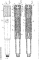
- the housing 4, in particular the inner sleeve 4a is in engagement with a sleeve-shaped driving member 8, which may also be referred to as a plunger.
- the propulsion member 8 is rotationally fixed relative to the housing 4 and axially along the longitudinal axis L. ( FIG. 2a ) displaceable.
- a guide is formed by means of at least one longitudinal rib 8a and at least one longitudinal guide 4c, which prevents rotation of the advancing member 8 relative to the housing 4 and allows axial movement of the advancing member 8 relative to the housing 4.
- the longitudinal rib 8a is preferably formed by an outer sleeve of the advancing member 8.
- the advancing member 8 has an inner sleeve 8b which, in this example, has at its proximal end an internal thread 8c which engages in an external thread 1a of a rotary member 1 designed as a threaded rod.
- the advancing member 8 is arranged so that its distal end 8d act on the piston 14a, in particular can press against the piston 14a.
- the spring 11 is supported with its distal end on an annular web of the driving member 8, which connects the outer sleeve and the inner sleeve of the driving member 8.
- the spring 11 is supported with its proximal end on the annular web formed by the housing 4 and projecting inwardly, which forms the abutment 4i.
- the discharge spring 11 is formed as a helical or spiral spring which acts as a compression spring and strives to push the abutment 4i and the advancing member 8 apart, d. H. to move the advancing member 8 in the distal direction relative to the housing 4.
- the discharge spring 11 is at delivery, d. H. is biased so strong in the initial state of the drive and metering that the energy stored in it is sufficient to substantially completely distribute the product contained in the product container 14, in particular with several individual distributions, between each of which a new dose setting is made.
- the advantage of such a highly biased spring is that the spring 11 is not z. B. during the dose adjustment must be tightened, which for the user of the device a power-saving, d. H. easier dose setting is vor Proceedingsbar.
- the threaded engagement between the driving member 8 and the rotary member 1 is so large that no self-locking of the threaded engagement occurs, ie, that the rotary member. 1 is rotatable or rotatable about the longitudinal axis L relative to the advancing member 8 due to the axial force of the discharge spring 11.
- the rotary member 1 is formed as a threaded rod which forms the external thread 1a and at its proximal end has an enlarged diameter, in particular in the form of a widened head.
- teeth 1b are arranged, which serve as a second coupling structure, as will be described below.
- an annular friction surface reduced in diameter relative to the head, which is in contact with the inwardly projecting annular web of the housing 4 forming the abutment 4i. Due to the reduced diameter of the annular friction surface of the point of application of the resulting friction force is moved closer to the longitudinal axis L, whereby the friction torque between the rotary member 1 and housing 4 is reduced.
- the spring 11 can move the driving member 8 by a Aus patternhub in the distal direction, which is proportional to the rotational angle of the rotary member 1.
- the drive and metering device further comprises a bearing element 9, which may also be referred to as a display drum bearing element and relative to the housing 4 rotatably but slidably disposed along the longitudinal axis L.
- the bearing element 9 fulfills the object of the displacement element described herein.
- the bearing element 9 is sleeve-shaped and preferably surrounds the inner sleeve 4 a of the housing 4, wherein in particular the outer sleeve 4 b surrounds the bearing element 9.
- the bearing element 9 is in engagement with the housing 4, in particular the inner sleeve 4a, which allows a longitudinal movement of the bearing element 9 relative to the housing 4, but prevents rotational movement.
- the engagement can be formed by a longitudinal guide 9f between the bearing element 9 and the inner sleeve 4a.
- the bearing element 9 has a thread 9a, in particular an external thread, into which a thread 10e, in particular an internal thread, of the dose indicator element 10 engages. Through this threaded engagement, the display element 10 can be screwed relative to the bearing element 9.
- the first embodiment further includes a signal generation mechanism 2e, 9b that generates an audible and / or tactile signal at the dose setting and product dispensing.
- the signal generating mechanism 2e, 9b is arranged between the coupling member 2 and the bearing element 9 and in particular comprises a locking member 2e and a toothing 9b.
- the bearing element 9 has a toothing 9b extending over the circumference, in particular the outer circumference.
- the coupling member 2 has the resiliently arranged and engaging in the toothing 9b locking member 2e.
- the bearing element 9 has at its proximal end on its circumference extending toothing 9b, z. B. for setting discrete dose-proportional angular increments and / or for generating a slight resistance in the dose setting and / or for generating the acoustic or tactile signal, such. B. an audible and tactile click in the dose setting and the product distribution serves.
- toothing 9b engage two locking members 2e, which are resiliently arranged on latching arms and are formed by the coupling member 2.
- the coupling member 2 is axially fixed to the bearing element 9 and rotatably connected relative to the bearing element 9.
- the coupling member 2 engages by means of an annular groove 2c in an over the circumference of the bearing element 9 extending annular projection 9d.
- a rotation of the sleeve-shaped coupling member 2 relative to the bearing element 9 causes the locking members 2e via the teeth 9b snap and thereby generate the acoustic and / or tactile signal.
- the dose indicator element 10 is rotatably, but axially displaceably connected to the coupling member 2, in particular in engagement.
- This engagement comprises a longitudinal guide 2a, which causes the dose indicator element 10 to rotate relative to the coupling member 2, but axially displaceable.
- a rotation of the coupling member 2 relative to the bearing element 9 causes due to the rotationally fixed connection between the coupling member 2 and Dose indicator 10, that the dose indicator 10 is also rotated and screwed due to the threaded engagement in the thread 9a on the bearing element 9 along, in particular in addition to the clicking noise generated due to the locking members 2e.
- the dose indicator element 10 has, over its outer circumference, a dose scale 10b which extends helically in accordance with the pitch of the thread 10e and which comprises a multiplicity of scale values arranged one after the other.
- a dose scale 10b which extends helically in accordance with the pitch of the thread 10e and which comprises a multiplicity of scale values arranged one after the other.
- the scale ranges from 0 to 80 and the dose values are given in 2-step increments.
- a marker 10a is arranged helically over the outer circumference of the dose indicator 10. This marking 10a serves - as will be described below - to indicate whether the device is actuated or unconfirmed.
- the marker 10a is an optional device. It may extend along the whole dose scale 10b or only parts or a single scale value thereof. In particular, when the drive and metering device is actuated, it can only be visible towards the end of the product discharge or in the zero-dose position.
- the dose indicator 10 has at its z. B. proximal end pointing in the circumferential direction and acting stop surface 10c, which is referred to as zero dose stop.
- the dose indicator 10 has at its, z. B. the proximal end opposite distal end on a circumferentially facing and acting stop surface 10d, which is referred to as maximum dose stop.
- the dose indicating element 10 can be screwed back and forth on the bearing element 9 between a zero dose position and a maximum dose position.
- the zero dose stop 10c in cooperation with a zero dose counter-stop 4f formed by the housing 4, prevents rotation of the dose indicating element 10 in a first rotational direction, namely a direction of rotation that would cause a dose smaller than zero to be set.
- the dose indicator element 10 is rotatable in the opposite, ie second, direction of rotation.
- the maximum dose stop 10d In cooperation with a maximum dose counteracting stop 9c formed by the bearing element 9, prevents rotation of the dose indicating element 10 in the second rotational direction, which would cause the dose to be increased beyond the maximum adjustable value.
- the rotation in the first direction of rotation is possible in the maximum dose position.
- the maximum dose counter stopper 9c is formed by the bearing member 9, unlike this example, the maximum dose counter stopper 9c may be optionally formed by the case 4.
- the zero dose counter stop can be formed by the bearing element 9.
- the housing 4 has a pointing device 4d in the form of a window, which exposes the scale 10b of the dose indicator element 10.
- a dosing member 3 in the form of a Dosierknopfs is rotatably mounted but axially fixed.
- the housing 4 an annular groove 4 g, in which engages in particular an annular shoulder of the dosing member 3.
- the dosing member 3 has over its outer periphery a handle structure 3b, which makes it easier for the user of the device to rotate the dosing member 3 relative to the housing 4.
- In the unactuated state of the device causes a rotation of the dosing member 3, a rotation or screw movement of the dose indicator element 10, whereby the desired dose is adjustable and readable in the pointing device 4d.
- an actuator 7 Disposed on the dosing member 3 is an actuator 7 in the form of an actuating button which is movable relative to the dosing member 3 for actuation of the product dispensing device, in particular along the longitudinal axis L.
- the actuator 7 forms the proximal end of the device and is from the thumb the hand of the user, which surrounds the housing 4, actuated in a simple manner, in particular relative to the housing 4 and / or to the dosing member 3 slidably.
- the coupling member 2 is rotatable and axially fixed relative to the actuating member 7, in particular when dissolved Dosierkupplung 2b, 3c.
- the actuator 7 with the coupling member 2 axially but rotatably snapped.
- the drive and metering device further comprises a reset or clutch spring 12 which is tensioned upon actuation, in particular pressing of the actuator 7 and which resets the bearing element 9 and / or the actuator 7 in its unactuated position when the actuator 7 is unactuated.
- An actuation of the actuator 7 causes in addition to its axial displacement also the axial displacement of the bearing element 9 along the longitudinal axis L.
- the spring 12 is supported with its distal end preferably on the dosing member 3 and with its proximal end preferably on the actuator 7 from.
- the spring 12 is preferably a helical or helical spring, which acts as a compression spring.
- the dosing member 3 is rotationally fixed relative to the actuator 7.
- the actuator 7 engages through an inwardly projecting shoulder of the dosing 3.
- a plurality of teeth are formed, which together form a toothing 7a, which 4h by actuation of the actuator 7 with a formed on the housing 4 teeth , in particular at the proximal end of the housing 4, come into engagement, whereby the dosing member 3 with respect to the housing 4 is non-rotatable.
- This causes a dose setting to be applied when the device is actuated, i. H. a rotation of the dosing member 3 relative to the housing 4 is not possible, but only when the actuator 7 is unactuated.
- the dosing member 3 forms a coupling structure 3c, in particular on the inwardly projecting shoulder.
- the coupling structure 3c acts together with unactuated actuator 7 with a coupling structure 2b on the outer circumference of the coupling member 2.
- the coupling between metering member 3 and coupling member 2 can also be referred to as Dosierkupplung 2b, 3c, which is engaged in the dose setting, ie unconfirmed actuator 7 and disengaged in the dose distribution, ie actuated actuator 7, wherein the clutch transmits torque in the engaged state and transmits no torque in the disengaged state.
- the metering coupling 2b, 3c is disengaged or opened relative to the housing 4 by a displacement of the coupling member 2, in particular due to the actuation of the actuating member 7.
- the bearing element 9 has at its proximal end on the inner circumference a first coupling structure 9e, which are formed by circumferentially arranged claws or teeth which are in engagement with the teeth or claws of the rotary member 1 forming the second coupling structure 1b, in particular when unactuated Actuator 7. Through this coupling engagement, the rotary member 1 with respect to the housing 4 is rotationally fixed.
- the coupling member 2 further includes a third coupling structure 2d on an inner circumference having a plurality of circumferentially distributed teeth or claws.
- the third coupling structure 2d is arranged such that upon actuation of the actuating member 7 it comes into rotationally fixed engagement with the rotary member 1, in particular with the second coupling structure 1b or alternatively with a fourth coupling structure separate from the second coupling structure 1b but not shown in this example ,
- the actuating member 7 While the actuating member 7 is displaced for actuation relative to the dosing member 3 along the longitudinal axis L, first the third coupling structure 2d engages the second coupling structure 1b. By further displacement of the actuator 7 relative to the metering member 3, the first coupling structure 9e comes out of engagement with the second coupling structure 1b. Before, after or simultaneously with the release of the engagement of the first coupling structure 9e with the second coupling structure 1b, the coupling structure 2b disengages from the coupling structure 3c and / or the toothing 7a engages with the toothing 4h.
- the discharge spring 11 can relax, rotating the rotation member 1 relative to the housing 4 and the coupling member 2 due to the engagement of the second coupling structure 1b with the third coupling structure 2d and thus also the dose indicator element 10 are rotated relative to the housing 4, whereby the dose indicator 10 is screwed back into its zero dose position and the advancing member 8 proportional to the in particular circumferentially extending distance between zero dose stop 10c and zero dose counter stop 4f to a Ausurgihub relative to the housing. 4 is moved in the distal direction.
- the rotation of the coupling member 2 relative to the bearing member 9 causes the locking members 2e over the teeth 9b snap in particular in dose-proportional angular steps and thereby generate the acoustic and / or tactile signal.
- the drive and metering device has a dose limiter 13 in the form of a ring, a ring segment or a nut which has on its inner circumference a thread 13b which engages in a arranged on an outer circumference of the housing 4 thread 4e, so that the limiter 13th can be screwed relative to the housing 4.
- the limiter 13 On the outer circumference, the limiter 13 has an engagement member 13a, which engages in a longitudinal guide 3a on the inner periphery of the dosing member 3, so that the dose limiter 13 relative to the dosing member 3 rotatably but axially displaceable.
- a stop stop is formed, of which the limiter 13 is spaced in proportion to the maximum amount of product to be distributed from the product container 14. Since in the dose setting the dosing member 3 is rotated relative to the housing 4 and not rotated at a dose distribution, a counter can be formed by the limiter 13, which adds the already distributed individual doses and the currently set dose and accordingly ever closer to the stop stop the dosing member 3 or the housing 4 approaches.
- a dose increase causes limiter 13 to be moved toward the stop stop.
- Dose reduction causes limiter 13 to be moved away from the stop stop.
- the limiter 13 comes into contact with the stop stop, so that a rotation of the dosing member 3 relative to the housing 4 in a rotational direction, the one Increasing the dose would result in being blocked.
- the coupling formed from the first, second and third and optionally also the fourth coupling structure 9e, 1b, 2d may also be referred to as a discharge coupling due to their interaction.
- the drive and metering device which may also be referred to as an injection device, is shown in its initial or delivery state, in particular before a first use.
- the product dose displayed in the pointing device 4d is 0.
- Actuating the actuator 7 would mean that no dose is distributed.
- the limiter 13 has a distance to the stop stop, which is proportional to the amount of product contained in the product container 14 or distributable, such. B. 300 IU
- the coupling member 2 and thus the dose indicator element 10 are rotated relative to the housing 4.
- the dose indicator element 10 screws along the bearing element 9 due to the threaded engagement of the thread 10e with the thread 9a.
- the distance between the zero dose stop 10c and the zero dose counterstop 4f is increased in proportion to the dose shown in the pointing device 4d.
- an audible and tactile signal is generated during the rotation due to the latching of the locking members 2e via the teeth 9b.
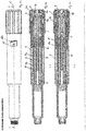
- FIGS. 3a to 3c the drive and metering device is shown in a state in which a maximum adjustable dose has been set, namely in this example 80 IU readable in the pointing device 4d.
- a further dose increase is not possible due to the interaction, in particular the contact of the maximum dose stop 10 d with the maximum dose counter-stroke 9 c.
- the dose limiter 13 is, as best of the FIGS. 3b and 3c recognizable, corresponding to 80 IU moved far to the stop stop or moved.
- the actuator 7 is actuated, in particular pressed, ie displaced relative to the housing 4 and the dosing member 3 in the distal direction, whereby the coupling member 2 and the bearing element 9 and the dose indicator 10 are displaced relative to the housing 4 in the distal direction, in particular against the force of the clutch or reset spring 12.
- the dose indicator element 10 is displaced axially relative to the housing 4 and the pointing device 4d
- the in FIG. 1 shown marking 10a in the pointing device 4d ( FIG. 4a ), whereby the user can visually read that the device is actuated.
- the mark 10a is moved from a position in which it comes from the housing 4 is moved to a position shown in the pointing device 14d along the longitudinal axis L.
- the actuation of the actuator 7 also causes the third coupling structure 2d to engage with the second coupling structure 1b and to disengage the first coupling structure 9e from the second coupling structure 1b so that the rotation member 1 is no longer rotatable but rotatable with respect to the housing 4 and in FIG With respect to the coupling member 2 and the dose indicator 10 is rotationally fixed.
- the actuation of the actuator 7 also causes the Dosierkupplung 2b, 3c disengages or is opened and the spur gear 7a into engagement with the spur gear 4h device.
- the rotary member 1 is rotationally fixed relative to the dose indicator 10, whereby the rotary member 1 and the dose indicator 10 can rotate together relative to the housing 4.
- the first coupling structure 9e is engaged with the second coupling structure 1b and the third coupling structure 2d is disengaged from the second coupling structure 1b.
- the rotary member 1 is now rotatable again in Referring to the housing 4, wherein the dosing member 3 is rotatable together with the dose indicator 10 relative to the housing 4 and / or the pointing device 4d and / or the rotary member 1 for a new setting of a product dose or single dose.
- the spur gear teeth 7a and 4h are released from the engagement and the Dosierkupplung 2b, 3c engaged again, whereby the dosing member 3 is rotatably relative to the coupling member 2 and the dose indicator element 10.
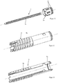
- FIG. 5a the drive and metering device is shown in a position in which the limiter 13 assumes its stop position, ie stops at the stop stop, whereby the limiter 13 blocks a dose setting to a value which exceeds the residual amount contained in the product container 14.
- 76 IU are still contained in the product container 14, with the drive and metering device would be adjustable to a maximum of 80 IU. Since the limiter 13 is already in contact with the stop stop at 76 IU, the dosing member 3 will be locked for rotation in the second direction, which would cause an increase in the dose. However, the reduction of the dose is possible by turning the dosing member 3 in the first direction of rotation.
- the drive and metering device or injection device is disposed of as a whole. It is thus a disposable injection device.
- the drive and metering devices shown herein can also be used in conjunction with reusable injection devices in which a deflated product container 14 is replaced with a new one.
- the inner sleeve 4a has a guide track 4m, which is in particular groove-shaped.
- the elongated guide track 4m extending along, in particular parallel to the longitudinal axis L, has a proximal guide track section and a distal guide track section, which are connected to one another by a transition section , in particular, merge into each other, as best of the FIGS. 6 and 7 is apparent.
- the proximal guide track section 4m is arranged angularly offset with respect to the distal guide track section about the longitudinal axis L.
- the groove-shaped guide track 4m is open at least to the outside or to the bearing element 9, wherein a projection 9i (FIG. FIG.
- the shape of the projection 9i may be adapted to the transition region between the proximal and distal guideway sections so that, when the projection 9i is displaced in the distal direction, the projection 9i is guided from the proximal guideway section into the distal guideway section, in particular through the transition section is that the bearing element 9 performs a rotational movement relative to the longitudinal axis L. Since in the example shown the projection 9i is firmly formed on the bearing element 9, the rotational movement exerted on it by the displacement of the projection 9i is transmitted to the bearing element 9.
- the projection 9i may, for example, be round, in particular circular, wherein the transition region between proximal and distal guide track sections may be chamfered or thread-shaped (not shown).
- the projection 9i is a rhombic cam 9i.
- the distal-directional end of the diamond-shaped cam 9i is displaced at least partially into the distal guide track section upon actuation of the confirmation member 7 by displacing the bearing member 9 in the distal direction from the proximal guide track section, with the proximal guide track section and the distal guide track section of the guide track 4m in the transition region relative to the angular position about the longitudinal axis L each other overlap.
- the oblique surface of the diamond-shaped cam which faces in the distal direction between the surfaces parallel to the longitudinal axis L, slides on the distal edge formed between the proximal and distal guideway portions, so that the diamond-shaped cam 9i and thus the Bearing element 9 are set in a rotational movement in the first direction of rotation about the longitudinal axis L.
- the diamond-shaped cam 9i has two parallel circumferentially facing surfaces, which are arranged parallel to the longitudinal axis L. These surfaces have a distance from one another which corresponds approximately to the width of the guide track 4m, in particular of the proximal and / or distal guideway section.
- the bearing element 9 has a first coupling structure 9e, which is designed as internal toothing and rotationally engages in the second coupling structure 1b, the rotary member 1, which is formed as external toothing, when the actuator 7 is unactuated or not in its (fully) actuated Position is.
- the first coupling structure 9e and the Abragung 9i are arranged to each other so that the bearing element 9 is already rotated in the first rotational direction when the clutch 9e, 1b is still closed, whereby the rotary member 1 is rotated. This is done in an intermediate position of the actuator 7 between the unactuated position and actuated position. If the actuator 7 is brought from the intermediate position to the actuated position, the clutch 9e, 1b is opened, whereby the rotary member 1 is rotationally driven by the discharge spring 11.
- the spring 12 returns the actuator 7 to its unactuated position with the oblique proximal facing surface of the cam 9i at the proximal edge formed between the proximal and distal guideway portions. from, so that the cam 9i and thus the bearing element 9 are set in a rotational movement in the second direction of rotation about the longitudinal axis L.
- the coupling 9e, 1b is closed in this case, so that the rotary member. 1 is also rotated in the second direction of rotation, whereby the distribution member 8 is moved at least a very small piece in the proximal direction.
- the piston of the product container 14 is relieved and the spring 11 at least minimally tensioned.
- the second embodiment of the FIGS. 10 to 14 comprises a designed as an internal toothing first coupling structure 9e on the inner circumference of the bearing element 9 (FIG. FIG. 14 ).
- the bearing element 9 is rotatable relative to the housing 4 and axially displaceable, wherein the inner sleeve 4a parallel to the longitudinal axis L has extending webs, which in corresponding recesses or grooves on the inner circumference of the bearing element 9 (Fig. FIG. 14 ) intervene.
- the rotary member 1 has a second coupling structure 1b, which is formed as an outer toothing.
- the rotary member 1 has at least one, preferably a plurality of gear surfaces 1e, which are arranged obliquely with respect to the longitudinal axis L and at which the first coupling structure 9e when operating the actuator 7 or during the displacement of the bearing member 9 in the distal direction relative to slides off the housing 4, whereby the rotary member 1 is set in a rotational movement when the actuator 7 is moved from its initial position to the actuated position.
- the first coupling structure 9e of the bearing member 9 is moved out of engagement with the second coupling structure 1b and into engagement with the gear surface 1e.
- the at least one gear surface 1e is formed by at least one projection, which preferably points radially outward.
- the projection 1e may be rib-shaped and preferably arranged distally of the second coupling structure 1b.
- the second coupling structure 1b, the first coupling structure 9e and the at least one gear surface 1e can be coordinated with one another such that the first coupling structure 9e is still in engagement with the second coupling structure 1b when the first coupling structure 9e slides off the gear surface 1e or off the engagement with the second coupling structure 1b is when the coupling structure 9e slides on the at least one gear surface 1e.
- an intermediate sleeve 16 is disposed between the rotary member 1 and the bearing element 9, in particular geometrically and / or kinematically.
- the intermediate sleeve 16 has a resiliently arranged Locking cam 16 b, which engages in an external toothing of the rotary member 1 resiliently, wherein the external toothing has a plurality of arranged over the circumference of the rotary member 1 sawtooth-shaped teeth.
- the external toothing is formed on the outer circumference of the rotary member 1.
- Due to the sawtooth shape of the external toothing causes the rotary member 1 in the rotation of the intermediate sleeve 16 in the first rotational direction, which causes a product discharge is taken, and that the rotary member 1 relative to the intermediate sleeve 16 in the first direction of rotation, which the discharge of the Product causes, can be turned.
- the intermediate sleeve 16 has a guide cam 16 a, which is formed on the outer circumference of the intermediate sleeve 16 and radially outward, d. H. protrudes away from the longitudinal axis L.
- the guide cam 16a engages in a groove-shaped guide track 9k, which is formed by the sleeve-shaped bearing element 9.
- the guide track 9k is open at least to the inner circumference or to the intermediate sleeve 16.
- the guideway 9k has a proximal guideway section and a distal guideway section interconnected by an intermediate section disposed obliquely to the distal and proximal guideway sections.
- the proximal and distal guideway portions are parallel to the longitudinal axis L and angularly offset with respect to each other about the longitudinal axis L.
- the guide cam 16a In the unactuated position of the actuator 7, the guide cam 16a is disposed in the distal guideway portion of the guideway 9k.
- the bearing member 9 connected to the housing 4 in a rotationally and axially displaceable manner is displaced in the distal direction relative to the guide cam 16a or to the intermediate sleeve 16 and in particular relative to the housing 4
- Guide cam 16a comes into engagement with the intermediate portion of the guide track 9k, so that the guide cam 16a and the intermediate sleeve 16 are rotated in the first rotational direction, whereby the rotary member 1 is taken from the intermediate sleeve 16 in the first rotational direction.
- the locking cam 16b is held in the toothing 1f, in particular by the inner circumference of the bearing element 9.
- the proximal guide track section of the guide track 9k is radially over the detent cam 16b so that the detent cam 16b extends radially can spring on the outside ( FIG. 18a ).
- the drive spring 11 and the closed clutch 1b, 2d the rotary member 1 is rotated relative to the intermediate sleeve 16 in the first rotational direction, so that the advancing member 8 is moved in the distal direction.
- the teeth 1f snap along the locking cam 16b, so that the locking cam 16b is resiliently pressed out of and into engagement with the toothing 1f.
- the teeth 1f do not necessarily need saw-toothed teeth but can generally be toothed be equipped, since the engagement of the locking cam 16b is effected in the teeth 1f upon rotation of the intermediate sleeve 16 in the first rotational direction, that the inner periphery of the bearing member 9 holds the locking cam 16b in engagement with the teeth 1f, so that this engagement is not is releasable, as long as the actuator 7 is not in its operating position.
- the bearing member 9 may alternatively be referred to as a slide member 9, as it fulfills the object of the slide member described herein.
- FIGS. 24 to 26 illustrated fourth embodiment solves the problem, a displacement of the dose display drum 10 along the longitudinal axis L relative to the pointer 4d and / or the housing 4 during the displacement of the actuator 7 to prevent.
- it may be advantageous if the indication of the dose is not affected by pressing the actuator 7, as long as the attachment member 7 has not yet reached its actuated position.
- FIGS. 24 and 26 embodiment shown can be in the Figures 1 to 5c modify the basic design shown for solving this claim. In the FIGS. 24 to 26 only those parts are shown which are necessary for understanding the modification and which in particular are changed.
- FIGS. 24 and 25 a portion of the outer sleeve 4b is shown, which are connected via radial webs (not visible, as hidden by the portion of the outer sleeve 4b) with the inner sleeve 4a.
- the inner sleeve 4a has analogous to the embodiment of the FIGS. 6 to 9 a groove-shaped guide track 4m.
- the guideway 4m is on the description of the FIGS. 6 to 9 directed. It should be noted, however, that the transition region between the proximal guideway portion and the distal guideway portion in the FIGS. 24 to 26 is further offset in the proximal direction, since the projection 9i is also located slightly further in the proximal direction than in the embodiment of the FIGS. 6 to 9 ,
- the bearing element 9 in this embodiment comprises two parts, namely a first bearing element part 9.1 and a second bearing element part 9.2.
- the bearing element part 9.1 in particular fulfills the object of the displacement element described herein and may optionally be referred to as a displacement element.
- the second bearing element part 9.2 has the external thread 9a, in which the internal thread of the dose indicator element 10 engages, so that the dose indicator element 10 can be screwed to the external thread 9a.
- the second bearing element part 9.2 is sleeve-shaped and can therefore be referred to as a second bearing element sleeve.
- the first bearing element part 9.1 is also sleeve-shaped and can therefore be referred to as the first bearing element sleeve 9.1.
- the first bearing element part 9.1 is axially fixed to the actuator 7 (see, for example FIG. 2b ), so that the first bearing element part 9.1 moves in the distal direction relative to the housing 4 upon actuation of the actuator 7 and moves relative to the housing 4 in the proximal direction when the actuator 7 is released.
- the first bearing element part 9.1 has - similar to the displacement member or bearing element 9 from the FIGS. 6 to 9 on its inner circumference an inwardly directed projection 9i, which is designed as a diamond-shaped cam.
- the projection 9i engages in the guide track 4m, namely in the proximal guide track section, when the actuator 7 is unactuated. If the actuating member 7 is actuated, ie displaced by the actuating stroke in the distal direction along the longitudinal axis L, and the projection 9i is moved into the transition region.
- the function corresponds to that of the FIGS. 6 to 9 , so that reference is made to the corresponding description.
- the first bearing element part 9.1 is rotated about the longitudinal axis L, namely in the first direction of rotation.
- the actuator 7 is released, the projection 9i moves in the proximal direction, whereby the inclined surface facing in the proximal direction slides off at the other proximal edge of the transition region, so that the first bearing element part 9.1 is rotated in the second direction of rotation.
- the first bearing element part 9.1 furthermore has the first coupling structure 9e in the form of an internal toothing (not visible).
- first coupling structure 9e is analogously to the description of the or on FIG. 9 directed.
- the first coupling structure 9e engages against rotation in the second coupling structure 1b, when the actuator 7 is operated unactuated or not fully.
- the first bearing element part 9.1 is already rotated when the clutch 9e, 1b is still closed. This causes the rotary member 1 is rotated with the first bearing element part 9.1.
- the function corresponds to that of the execution of the FIGS. 6 to 9 , which is why reference is additionally made to the corresponding parts of the description.
- the first bearing element part 9.1 and the second bearing element part 9.2 engage in an axially displaceable and non-rotatable manner.
- the second bearing element part 9.2 makes the rotation of the first bearing element part 9.1.
- the second bearing element part 9.2 is decoupled from the axial movement of the first bearing element part 9.1. This causes the second bearing element part 9.2 is not moved along the longitudinal axis L, whereby the dose indicator element 10 - apart from turning back during the product distribution - relative to the pointing device 4d of the housing 4 along the longitudinal axis L is not displaced.
- the first bearing element part 9.1 has two legs 9n directed in the distal direction, between which engage in the circumferential direction two legs 9m, which are formed by the second bearing element part 9.2 and project from its proximal end.
- the legs 9m, 9n guide each other and thereby prevent the first bearing element part 9.1 is rotatable relative to the second bearing element part 9.2, but at the same time allow the first bearing element part 9.1 relative to the second bearing element part 9.2 along the longitudinal axis L is displaceable.
- a circumferentially extending groove 4n is arranged on the inner sleeve 4a, into which engages an engagement member 91, in particular a projection on the inner circumference of the second bearing element part 9.2.
- the coupling member 2 ( Figures 1 to 5c ) engages axially fixed and rotatable in the first bearing element part 9.1, for which the first bearing element part 9.1, for example, at its proximal end has an annular circumferential collar.
- the clutch 1b, 9e, the clutch 1b, 2d, the cam 9i and the transition region are coordinated and in particular positioned with respect to each other so that during the displacement of the actuator 7 from the unactuated position to the actuated position, the clutch 2d, 1b closed, then the bearing element part 9.1 is rotated by means of the cam 9i and only after the beginning of the rotation of the bearing element part 9.1, the coupling 1b, 9e are opened.
- the dose indicator drum 10 performs, in particular due to the closed coupling 1b, 2d, during the rotation of the bearing member part 9.1 a rotation, in particular without movement along the longitudinal axis L, relative to the pointing device 4d and / or the housing 4. In the meantime, no rotational movement and thus no screwing motion between the bearing element part 9.2 and the dose indicating drum 10 takes place.
Landscapes
- Health & Medical Sciences (AREA)
- Vascular Medicine (AREA)
- Engineering & Computer Science (AREA)
- Anesthesiology (AREA)
- Biomedical Technology (AREA)
- Heart & Thoracic Surgery (AREA)
- Hematology (AREA)
- Life Sciences & Earth Sciences (AREA)
- Animal Behavior & Ethology (AREA)
- General Health & Medical Sciences (AREA)
- Public Health (AREA)
- Veterinary Medicine (AREA)
- Infusion, Injection, And Reservoir Apparatuses (AREA)
Description
- Die Erfindung liegt auf dem Gebiet der Injektionsvorrichtungen zum Verabreichen eines flüssigen Produkts, insbesondere eines Medikaments, wie z. B. Insulin zur Diabetestherapie. Die Erfindung betrifft eine Antriebsvorrichtung, wie z. B. eine Antriebs- und Dosiervorrichtung für eine solche Injektionsvorrichtung.
- Aus dem Stand der Technik, nämlich der
WO 2008/031237 A1 ist ein Injektionsgerät mit einer Dosisanzeigetrommel und einer Antriebsfeder bekannt. Die Antriebsfeder ist eine Uhrenfeder, die spiralförmig aus einem bandförmigen Material gewickelt ist. Beim Einstellen der gewünschten Produktdosis wird die Feder mit einer rotatorischen Bewegung gespannt. Für die Dosisausschüttung wird durch Betätigen eines Betätigungsknopfs am proximalen Ende der Vorrichtung eine Kolbenstange der Vorrichtung mit der Feder gekoppelt, wodurch die Feder die in ihr gespeicherte Energie an die Kolbenstange abgeben kann, wodurch die Kolbenstange in Ausschüttrichtung bewegt wird. Zum Einstellen einer neuen Dosis wird die Feder durch Drehen des Dosierknopfs wieder vorgespannt und so weiter. Dies wird so oft wiederholt, bis der Produktbehälter geleert ist. - In den Patentanmeldungen
WO 2002/092153 undEP 2644217 wird eine Antriebs- und Dosiervorrichtung beschrieben, wie sie in den beigefügtenFiguren 1 bis 5c dargestellt wird. Diese Vorrichtung weist eine Antriebsfeder auf, die im Auslieferungszustand der Antriebs- und Dosiervorrichtung mit soviel Energie vorgespannt ist, dass sie die aus dem Produktbehälter ausschüttbare Produktmenge in mehreren Einzelausschüttungen ausschütten kann. Die Ausschüttfeder treibt ein Rotationsglied an, dessen Rotation bewirkt, dass ein Vortriebsglied den Kolben eines Produktbehälters verschiebt, wodurch das in dem Produktbehälter enthaltene Produkt ausgeschüttet wird. Für die Produktausschüttung wird ein Druckknopf betätigt, wodurch eine geschlossene Kupplung geöffnet wird, wobei die geöffnete Kupplung die Drehung des Rotationsglieds zulässt und die geschlossene Kupplung die Drehung des Rotationsglieds nicht zulässt. - Derartige Injektionsvorrichtungen setzen voraus, dass die vorgespannte Ausschüttfeder ohne weiteres Zutun die Produktausschüttung startet, wenn der Betätigungsknopf bzw. Druckknopf vollständig betätigt ist. Da solche Injektionsvorrichtungen mitunter lange bis zu ihrer Verwendung lagern können, kann es sein, dass der Mechanismus "fest" wird bzw. sich nicht ordnungsgemäß löst, wenn der Betätigungsknopf vollständig gedrückt ist, so dass eine Produktausschüttung z. B. verzögert startet oder erst durch leichtes Klopfen (mechanisches Erschüttern) gegen die Injektionsvorrichtung startet.
- Es ist eine Aufgabe der Erfindung eine Antriebsvorrichtung für eine Injektionsvorrichtung anzugeben, die sicherstellt, dass die Produktausschüttung bei betätigtem Betätigungsglied startet.
- Die Aufgabe wird durch die Merkmale des Anspruchs 1 gelöst. Vorteilhafte Weiterbildungen ergeben sich aus den abhängigen Ansprüchen, der Beschreibung und den Figuren.
- Die Erfindung geht von einer Antriebsvorrichtung, insbesondere einer Antriebs- und Dosiervorrichtung, für eine Injektionsvorrichtung zum Verabreichen eines flüssigen Medikaments oder Produkts aus. Mit der Antriebsvorrichtung kann eine feste oder nicht veränderbare Dosis ausgeschüttet oder eine Dosis eingestellt und anschließend ausgeschüttet werden. Sofern die Antriebsvorrichtung die Einstellung einer, z. B. variablen, Dosis erlaubt, wie z. B. durch Verdrehen eines vom Verwender greifbaren Dosierglieds, kann sie auch als Antriebs- und Dosiervorrichtung bezeichnet werden.
- Die Antriebsvorrichtung weist ein Gehäuse auf. Das Gehäuse ist vorzugsweise hülsenförmig und/oder länglich ausgebildet. Das Gehäuse kann sich z. B. entlang seiner Längsachse erstrecken.
- Das Gehäuse kann optional einen Produktbehälter aufnehmen oder selbst den Produktbehälter bilden. Das Gehäuse kann ein- oder mehrteilig sein. Z. B. kann das Gehäuse einen proximalen Gehäuseteil bilden, der die Antriebsvorrichtung umfasst oder aufweist. Das Gehäuse kann ferner einen Produktbehälterhalter aufweisen, der den Produktbehälter, wie z. B. eine Karpule, aufnimmt und mit dem Gehäuse oder dem proximalen Gehäuseteil verbunden ist. Diese Verbindung kann derart sein, dass der Produktbehälterhalter und das Gehäuse oder der proximale Gehäuseteil nach dem Verbinden unlösbar, d. h. nur durch Zerstörung von Verbindungselementen lösbar ist. Eine solche Ausführung ist insbesondere bei Einweginjektionsvorrichtungen von Vorteil, die nach dem das in dem Produktbehälter enthaltene Produkt vollständig ausgeschüttet ist, als Ganzes entsorgt werden. Alternativ kann der Produktbehälterhalter auch lösbar an dem Gehäuse befestigt werden, wodurch es möglich ist, die Antriebsvorrichtung gegebenenfalls mehrfach zu verwenden, d. h. einen leeren Produktbehälter gegen einen gefüllten Produktbehälter auszutauschen.
- Das Gehäuse dient vorzugsweise dazu, vom Verwender der Vorrichtung ergriffen zu werden. Insbesondere kann das Gehäuse eine im Wesentlichen zylindrische Form aufweisen. Das Gehäuse kann z. B. eine Zeigeeinrichtung, insbesondere ein Fenster aufweisen, mittels der oder durch welches eine aktuell eingestellte Dosis, vorzugsweise von einer Skala eines Dosiseinstelleelements, ablesbar ist.
- Die Antriebsvorrichtung kann ein Vortriebsglied aufweisen, dessen distales Ende vorgesehen ist, auf einen Kolben, insbesondere mittelbar oder vorzugsweise unmittelbar zu wirken. Der Kolben kann Teil eines an der Antriebsvorrichtung befestigten oder befestigbaren Produktbehälters, wie z. B. einer Karpule sein. Das Vortriebsglied kann im weiteren Sinne als Kolbenstange bezeichnet werden, wobei das Vortriebsglied nicht notwendigerweise massiv sein muss, sondern auch hohl, wie z. B. hülsenförmig ausgestaltet sein kann. An dem distalen Ende des Vortriebsglieds kann optional ein z. B. drehbarer Flansch gebildet sein, der gegen den Kolben drückt. Allgemein ist es bevorzugt, dass das distale Ende des Vortriebsglieds gegen den Kolben drückt. Das Vortriebsglied ist vorzugsweise relativ zu dem Gehäuse entlang der Längsachse der Antriebsvorrichtung verschiebbar.
- Die Antriebsvorrichtung kann ein Widerlager und vorzugsweise eine Führung aufweisen, wobei das Vortriebsglied relativ zu dem Widerlager und vorzugsweise auch relativ zu der Führung in eine Richtung, insbesondere in die distale Richtung, d. h. in die Ausschüttrichtung, bewegbar ist, um eine Ausschüttung des Produkts oder ggf. der oder einer eingestellten Produktdosis zu bewirken. Vorzugsweise kann das Vortriebsglied mittels oder an der Führung, entlang der Längsachse der Antriebsvorrichtung gerade oder axial geführt sein. Insbesondere kann das Vortriebsglied relativ zu dem Widerlager oder/und der Führung oder/und dem Gehäuse drehfest sein. In einer alternativen Ausführungsform kann das Vortriebsglied relativ zu dem Widerlager oder dem Gehäuse kombiniert mit einer Längsbewegung drehbar, d. h. relativ zu dem Widerlager schraubbar sein. Allgemein kann die Führung oder/und das Widerlager von dem Gehäuse, insbesondere einem hülsenförmigen Gehäuseteil oder einem z. B. hülsenförmigen, gehäusefesten Element gebildet werden.
- Das Vortriebsglied und die insbesondere von dem Gehäuse gebildete Führung können in einem Eingriff sein, der eine Drehung des Vortriebsglieds relativ zu dem Widerlager oder dem Gehäuse verhindert und eine Axialbewegung, oder eine Schraubbewegung des Vortriebsglieds relativ zu dem Widerlager oder dem Gehäuse erlaubt. Die Führung kann z. B. eine Axialführung oder ein Gewinde mit einer nicht selbsthemmenden Gewindesteigung sein.
- Die Führung oder der das Widerlager oder/und die Führung bildende Gehäuseabschnitt, insbesondere eine Innenhülse, kann vorzugsweise das Vortriebsglied umgeben, wie z. B. hülsenförmig umgeben und/oder gehäusefest sein oder von dem Gehäuse gebildet werden. Zwischen diesem hülsenförmigen Gehäuseteil und einem äußeren, vorzugsweise ebenfalls hülsenförmigen Gehäuseteil kann ein Ringspalt gebildet sein, der den Vorteil birgt, dass ein optional vorhandenes Dosisanzeigeelement, insbesondere eine Dosisanzeigetrommel, darin z. B. bewegbar aufgenommen sein kann. Dies bewirkt, dass die Länge der Antriebsvorrichtung gering gehalten werden kann.
- Die Antriebsvorrichtung kann mindestens eine, wie z. B. genau eine, zwei oder drei zwischen dem Vortriebsglied oder einem Rotationsglied und dem Widerlager wirkende und insbesondere angeordnete Ausschüttfeder aufweisen. Die mindestens eine Feder kann sich z. B. an dem Vortriebsglied und/oder dem Widerlager abstützen. Beispielsweise kann sich die z. B. einzige Ausschüttfeder mit ihrem distalen Ende an dem Vortriebsglied und mit ihrem proximalen Ende an dem Widerlager abstützen. Insbesondere kann die mindestens eine Ausschüttfeder innerhalb der Führung oder des die Führung bildenden hülsenförmigen Gehäuseteils angeordnet sein. Ist das Vortriebsglied hülsenförmig, kann die mindestens eine Ausschüttfeder innerhalb des Vortriebsglieds angeordnet sein. Alternativ können eine erste Ausschüttfeder und eine zweite Ausschüttfeder insbesondere kinematisch zwischen dem Vortriebsglied und der Führung oder dem die Führung bildenden hülsenförmigen Gehäuseteil angeordnet sein. Die erste Ausschüttfeder kann z. B. die zweite Ausschüttfeder umgeben oder umgekehrt. Insbesondere kann die zweite Ausschüttfeder konzentrisch zur ersten Ausschüttfeder angeordnet sein. Die erste Ausschüttfeder und die zweite Ausschüttfeder können z. B. parallel oder in Serie geschaltet sein. Parallel geschaltete Ausschüttfedern bedeuten insbesondere, dass sich die erste und zweite Ausschüttfeder jeweils mit ihrem distalen Ende an dem Vortriebsglied und jeweils mit ihrem proximalen Ende an dem Widerlager abstützen können. Hierdurch lassen sich die Federkonstanten der ersten und zweiten Ausschüttfeder zu einer Gesamtfederkonstante addieren. In Serie geschaltete Ausschüttfedern bedeutet insbesondere, dass das distale Ende von einer aus erster und zweiter Ausschüttfeder gegen das proximale Ende der anderen aus erster und zweiter Ausschüttfeder drückt, insbesondere unmittelbar oder vorzugsweise mittelbar, wie z. B. über ein Zwischenglied. Z. B. stützt sich die erste Ausschüttfeder an dem Widerlager und dem Zwischenglied und die zweite Ausschüttfeder an dem Zwischenglied und dem Vortriebsglied ab. Beispielsweise kann das distale Ende der ersten Ausschüttfeder distal des proximalen Endes der zweiten Ausschüttfeder angeordnet sein. Aufgrund des Zwischenglieds kann die Federkraft der ersten Feder von ihrem distalen Ende auf das proximale Ende der zweiten Ausschüttfeder übertragen werden. Insbesondere kann das Zwischenglied hülsenförmig sein und in einem Ringspalt zwischen erster und zweiter Ausschüttfeder angeordnet sein. In Serie geschaltete Ausschüttfedern erlauben, über einen verhältnismäßig langen Federweg eine verhältnismäßig gleich bleibende Federkraft.
- Z. B. kann die mindestens eine Ausschüttfeder, insbesondere die erste und zweite Ausschüttfeder eine Wendel- oder Schraubenfeder sein, die als Druckfeder oder als Torsionsfeder wirkt. Die mindestens eine Ausschüttfeder ist vorgespannt und wirkt so auf das Vortriebsglied, das sie versucht, das Vortriebsglied relativ zu dem Widerlager in die distale Richtung, d. h. in die Ausschüttrichtung zu verschieben. Die mindestens eine Ausschüttfeder ist im Auslieferungszustand der Antriebs- und Dosiervorrichtung insbesondere mit so viel Energie vorgespannt, dass sie die aus dem Produktbehälter maximal oder insgesamt ausschüttbare Produktmenge, zum Beispiel in mehreren Einzelausschüttungen, d. h. insbesondere in mehreren Ausschüttungen einzelner Produktdosen, ausschütten kann.
- Die Antriebsvorrichtung kann, wenn mit ihr eine Dosis einstellbar ist, so ausgestaltet sein, dass nach jeder Einzelausschüttung oder Ausschüttung der Produktdosis, die nächste auszuschüttende Dosis neu eingestellt wird. Die Antriebsvorrichtung kann ein Dosierglied aufweisen, das zum Beispiel als Dosierknopf ausgebildet ist und optional als Dosiseinstellglied bezeichnet werden kann. Im Gegensatz zu Ausführungen, bei denen eine Ausschüttfeder bei jeder Dosiseinstellung neu vorgespannt wird, kann durch die mit der für die Ausschüttung der maximal aus dem Produktbehälter ausschüttbaren Produktmenge erforderlichen Energie vorgespannte Feder eine einfachere Dosiseinstellung erreicht werden, da das für die Dosiseinstellung relativ zu dem Gehäuse drehbare Dosierglied dann einfacher drehbar ist, weil die Feder bei der Dosiseinstellung nicht vorgespannt werden braucht. Dies erhöht den Anwendungskomfort für den Verwender der Vorrichtung.
- Die Antriebsvorrichtung kann ferner ein Rotationsglied umfassen, dessen Drehung bewirkt, dass die Feder Energie an das Vortriebsglied abgibt, wodurch das Vortriebsglied in die distale Richtung bewegt wird. Das Rotationsglied übernimmt vorzugsweise die Funktion eines Steuerglieds, wobei die Drehung des Rotationsglieds um einen bestimmten Drehwinkel den Vorschub des Vortriebsglieds um einen bestimmten Ausschütthub bewirkt. Durch selektive Freigabe oder Sperrung einer Drehung des Rotationsglieds relativ zu dem Gehäuse kann der Feder erlaubt werden, dass sie das Vortriebsglied relativ zu dem Widerlager in die distale Richtung bewegen kann oder nicht bewegen kann. Insbesondere kann das Rotationsglied so mit dem Betätigungsglied gekoppelt sein, dass es bei der Betätigung des Betätigungsglieds für eine Produktausschüttung für eine Drehung relativ zu dem Gehäuse freigegeben ist und bei Nichtbetätigung des Betätigungsglieds für eine Rotation relativ zu dem Gehäuse gesperrt ist. Insbesondere kann zwischen Betätigungsglied und Rotationsglied eine Kupplung, insbesondere Ausschüttkupplung, angeordnet sein, welche die Freigabe und Sperrung der Drehung des Rotationsglieds relativ zu dem Gehäuse bewirkt. Die geschlossene Kupplung kann durch Betätigen, insbesondere Drücken des Betätigungsglieds geöffnet werden, wobei die geöffnete Kupplung die - mittels der vorgespannten Feder bewirkbare - Drehung des Rotationsglieds, insbesondere Ausschüttfeder, relativ zu dem Gehäuse freigibt.
- Vorteilhaft kann die Kupplung durch Betätigen des Betätigungsglieds die Drehung des Rotationsglieds relativ zu dem Gehäuse freigeben und durch Loslassen des Betätigungsglieds die Drehung des Rotationsglieds relativ zu dem Gehäuse blockieren.
- Das Betätigungsglied ist so mit dem Rotationsglied gekoppelt, dass das Betätigen, insbesondere das Drücken des Betätigungsglieds bewirkt, dass sich das Rotationsglied relativ zu dem Gehäuse bereits dann dreht, wenn die Kupplung noch geschlossen ist. Das Betätigungselement ist zwischen einer unbetätigten, d. h. ungedrückten Position, und einer betätigten Position, d. h. gedrückten Position, hin und her verschiebbar, insbesondere entlang der Längsachse der Antriebsvorrichtung. Durch die Verschiebung des Betätigungsglieds aus der unbetätigten in die betätigte Position wird das Rotationsglied relativ zu dem Gehäuse bereits dann gedreht, wenn die Kupplung noch geschlossen ist. Die unbetätigte Position kann auch als Ausgangsposition des Betätigungsglieds bezeichnet werden. Die Kupplung ist geöffnet, wenn das Betätigungsglied in seiner betätigten Position ist. Das Betätigungsglied ist mit dem Rotationsglied über ein Getriebe gekoppelt, welches die Bewegung des Betätigungsglieds entlang der Längsachse L, insbesondere in die distale Richtung, in eine Drehbewegung des Rotationsglieds, insbesondere in die erste Drehrichtung, umwandelt. Durch die Drehung des Rotationsglieds bereits dann, wenn die Kupplung noch geschlossen ist, lässt sich vorteilhaft erreichen, dass die mit der Zeit möglicherweise zueinander festgewordenen Teile gelöst werden, insbesondere durch die Muskelkraft des Verwenders, welche das Betätigungsglied in die distale Richtung drückt.
- Bevorzugt ist, dass die durch das Betätigen des Betätigungsglieds bewirkte Drehung des Rotationsglieds relativ zu dem Gehäuse bei geschlossener Kupplung kleiner als 45°, insbesondere kleiner als 20° ist. Vorzugsweise ist die durch das Betätigen des Betätigungsglieds bewirkte Drehung des Rotationsglieds relativ zu dem Gehäuse in die gleiche Drehrichtung, insbesondere in die erste Drehrichtung, alternativ in die entgegensetzte Drehrichtung, insbesondere die zweite Drehrichtung gerichtet, wie die Drehrichtung der mittels der vorgespannten Feder bewirkbaren Drehung des Rotationsglieds. Die mittels der vorgespannten Feder bewirkbare Drehung des Rotationsglieds erfolgt in die erste Drehrichtung.
- Insbesondere kann das Betätigungsglied so mit dem Rotationsglied gekoppelt sein, dass das Zurückbewegen des Betätigungsglieds aus seiner betätigten Positionen in seine unbetätigte Position, insbesondere das Loslassen des Betätigungsglieds, bewirkt, dass sich das Rotationsglied relativ zu dem Gehäuse in eine Drehrichtung, insbesondere in die zweite, d. h. der ersten Drehrichtung entgegengesetzte Drehrichtung, dreht, die der Drehrichtung, insbesondere der ersten Drehrichtung, der mittels der vorgespannten Feder bewirkbaren Drehung entgegengesetzt ist. Dieser Effekt kann mittels des oben genannten Getriebes erfolgen. Insbesondere kann das Betätigungsglied von einer Feder, insbesondere einer Rücksetz- oder Kupplungsfeder, die durch das Betätigen des Betätigungsglieds vorgespannt wird, aus seiner betätigten Position in seine unbetätigte Position zurückbewegt werden. Diese Feder kann hierdurch das Rotationsglied, insbesondere über das Getriebe, in die zweite Drehrichtung drehen.
- Insbesondere in Ausführungsformen, in denen das Loslassen des Betätigungsglieds bewirkt, dass sich das Rotationsglied relativ zu dem Gehäuse in die zweite Drehrichtung dreht, ist es bevorzugt, dass der Kolben des Produktbehälters bei der Produktausschüttung oder bei der Drehung des Rotationsglieds in die erste Drehrichtung von dem auf ihn in Ausschüttrichtung wirkenden Vortriebsglied in Ausschüttrichtung verschoben wird und dass beim Zurückbewegen des Betätigungsglieds in seine unbetätigte Position das Vortriebsglied entgegen die Ausschüttrichtung relativ zu dem Widerlager bewegt wird, insbesondere soweit, dass der Kolben von dem Druck des Vortriebsglieds entlastet wird. Durch die Drehung des Rotationsglieds in die zweite Drehrichtung wird bewirkt, dass das Vortriebsglied ein zumindest sehr kleines Stück in die proximale Richtung, d. h. entgegen die Ausschüttrichtung, bewegt wird, so dass der Kolben des Produktbehälters entlastet wird. Dabei kann die Ausschüttfeder wieder etwas gespannt werden. Vorzugsweise ist die Kupplung bereits geschlossen, wenn sich das Vortriebsglied in die proximale Richtung bewegt.
- Das oben genannte Getriebe kann ein erstes Getriebeelement und ein zweites Getriebeelement aufweisen. Ein erstes Teil kann das erste Getriebeelement und ein zweites Teil das zweite Getriebeelement bilden, wobei das erste Getriebeelement das zweite Getriebeelement durch die Betätigung des Betätigungsglieds aneinander abgleiten, wodurch das Betätigen, insbesondere das Drücken des Betätigungsglieds bewirkt, dass sich das Rotationsglied relativ zu dem Gehäuse bereits dann, insbesondere in die erste Drehrichtung, dreht, wenn die Kupplung noch geschlossen ist.
- In einer Ausführungsform kann das Gehäuse oder ein gehäusefestes Element das erste Teil und ein die Kupplung mitbildendes, zum Beispiel hülsenförmiges Verschiebeglied, insbesondere ein Lagerelement, welches zumindest axial verschiebbar in Bezug auf das Gehäuse oder das gehäusefeste Element ist, das zweite Teil sein. Das Verschiebeglied kann das gehäusefeste Element umgeben. Das erste Teil und das zweite Teil können so ineinandergreifen, dass eine durch Betätigen des Betätigungsglieds bewirkte Verschiebung des zweiten Teils eine Verdrehung des zweiten Teils relativ zu dem ersten Teil bewirkt. Beispielsweise kann eines aus erstem Teil und zweitem Teil ein Eingriffsglied aufweisen, wobei das andere aus erstem und zweitem Teil eine Führungsbahn aufweist, wobei eine Bewegung des Eingriffsglieds in der Führungsbahn eine Verdrehung des zweiten Teils relativ zu dem ersten Teil bewirkt. Zum Beispiel kann die Führungsbahn ein Gewinde oder ein Gewindeabschnitt sein. Beispielsweise kann die Führungsbahn einen proximalen und/oder einen distalen Führungsbahnabschnitt aufweisen, die über einen Übergangsabschnitt miteinander verbunden sind oder wobei sich ein Übergangsabschnitt an den proximalen oder distalen Führungsbahnabschnitt anschließt. Das Eingriffsglied kann, wenn es in der Führungsbahn, insbesondere in dem oder durch den Übergangsabschnitt bewegt wird, eine Verdrehung des zweiten Teils relativ zu dem ersten Teil bewirkt, insbesondere in die erste Drehrichtung, wenn das Betätigungsglied betätigt wird und sich das Eingriffsglied in eine erste Richtung in der Führungsbahn oder durch den oder in dem Übergangsabschnitt bewegt, und insbesondere in die zweite Drehrichtung, wenn das Betätigungsglied losgelassen wird und sich das Eingriffsglied in eine zweite Richtung, die der ersten Richtung entgegengesetzt ist, in der Führungsbahn oder durch den oder in dem Übergangsabschnitt bewegt. Zum Beispiel können der proximale Führungsbahnabschnitt und/oder der distale Führungsbahnabschnitt parallel zu der Längsachse sein, so dass das zweite Teil relativ zu dem ersten Teil drehfest und axial verschiebbar ist, wenn sich das Eingriffsglied in dem proximalen oder dem distalen Führungsbahnabschnitt befindet.
- In einer weiteren Ausführungsform kann das die Kupplung mitbildende Rotationsglied das erste Teil und ein die Kupplung mitbildendes Verschiebeglied, insbesondere das Lagerelement, welches relativ zu dem Gehäuse oder einem gehäusefesten Element drehfest und entlang der Längsachse der Antriebsvorrichtung verschiebbar ist, das zweite Teil sein. Beispielsweise können das erste Teil und das zweite Teil während der Verschiebung des zweiten Teils, die durch das Betätigen oder das Loslassen des Betätigungsglieds verursacht wird, aneinander abgleiten, wodurch das erste Teil relativ zu dem Gehäuse gedreht wird, insbesondere in die erste Drehrichtung, wenn das Betätigungsglied betätigt wird, und/oder in die zweite Drehrichtung, wenn das Betätigungsglied losgelassen wird. Das erste Teil und das zweite Teil können ineinandergreifen. Beispielsweise kann das erste Teil Abragungen aufweisen, welche zu dem zweiten Teil weisen, wobei das zweite Teil Abragungen aufweisen kann, welche zu dem ersten Teil weisen. Die zueinander weisenden und ineinandergreifenden Abragungen können aneinander abgleiten, wenn das Betätigungsglied betätigt wird. Die Abragungen können zum Beispiel Teil der Kupplungsstruktur der genannten Kupplung sein, wobei die Kupplung erst gelöst ist, wenn die vorzugsweise zueinander weisenden Abragungen aneinander abgeglitten und aus dem Eingriff sind. Hierdurch kann sich das Rotationsglied relativ zu dem Gehäuse und dem zweiten Teil mittels der vorgespannten Ausschüttfeder in die erste Drehrichtung drehen.
- In noch weiteren Ausführungen kann das Rotationsglied eine Verzahnung oder Vielzahl über seinen Umfang angeordnete, z. B. sägezahnförmige, Zähne aufweisen, in die eine Rastnocke, die von einer über den Umfang des Rotationsglieds angeordneten Zwischenhülse, gebildet ist, federnd eingreift, wobei die Zwischenhülse das erste Teil ist und eine Kupplungsstruktur der Kupplung bildet und ein Verschiebeglied, insbesondere ein Lagerelement, welches drehfest und axial verschiebbar in Bezug auf das Gehäuse oder ein gehäusefestes Element ist, das zweite Teil ist, wobei das bevorzugt hülsenförmige Verschiebeglied die Zwischenhülse über ihren Umfang umgibt. Die Zwischenhülse kann konzentrisch zwischen dem Rotationsglied und dem Verschiebeglied angeordnet sein. Zum Beispiel kann eines aus Verschiebeglied und Zwischenhülse eine Abragung aufweisen, welche in eine Führungsbahn des anderen aus Verschiebeglied und Zwischenhülse eingreift. Zum Beispiel kann die Führungsbahn ein Gewinde oder ein Gewindeabschnitt sein. Beispielsweise kann die Führungsbahn einen proximalen und/oder einen distalen Führungsbahnabschnitt aufweisen, die über einen Übergangsabschnitt miteinander verbunden sind oder wobei sich ein Übergangsabschnitt an den proximalen oder distalen Führungsbahnabschnitt anschließt. Die Abragung bewirkt, wenn sie in der Führungsbahn, insbesondere in dem Übergangsabschnitt, bewegt wird, eine Verdrehung der Zwischenhülse und insbesondere des Rotationsglieds relativ zu dem Verschiebeglied, insbesondere in die erste Drehrichtung, wenn das Betätigungsglied betätigt wird und sich die Abragung in eine erste Richtung in der Führungsbahn, insbesondere durch den oder in dem Übergangsabschnitt bewegt, und insbesondere in die zweite Drehrichtung, wenn das Betätigungsglied losgelassen wird und sich die Abragung in eine zweite Richtung, die der ersten Richtung entgegengesetzt ist, in der Führungsbahn, insbesondere durch den oder in dem Übergangsabschnitt bewegt. Zum Beispiel können der proximale Führungsbahnabschnitt und/oder der distale Führungsbahnabschnitt parallel zu der Längsachse sein, so dass die Zwischenhülse relativ zu dem Verschiebeglied drehfest und axial verschiebbar ist, wenn sich die Abragung in dem proximalen oder dem distalen Führungsbahnabschnitt befindet. Vorteilhaft bewirken die Führungsbahn und die in die Führungsbahn eingreifende Abragung, dass sich die Zwischenhülse in die erste Drehrichtung dreht, wenn das Betätigungsglied betätigt wird, d. h. aus seiner unbetätigten Position in seine betätigte Position verschoben wird.
- Der Eingriff der Rastnocke in die über den Umfang angeordneten Zähne ist so, dass eine Drehung der Zwischenhülse relativ zu dem Rotationsglied in die erste Drehrichtung verhindert wird und eine Drehung des Rotationsglieds relativ zu der Zwischenhülse in die erste Drehrichtung möglich ist. Die Betätigung des Betätigungsglieds bewirkt eine Drehung der Zwischenhülse in die erste Drehrichtung relativ zu dem Gehäuse, wobei die Zwischenhülse das Rotationsglied mitnimmt, d. h. mitdreht. Wenn das Betätigungsglied in seiner betätigten Position ist, kann die Antriebsfeder das Rotationsglied relativ zu der Zwischenhülse in die erste Drehrichtung drehen, da die Kupplung geöffnet ist. Beispielsweise kann das Kupplungsglied, insbesondere das Lagerelement oder dessen Innenfläche, wie z. B. der Innenumfang, die Rastnocke daran hindern, aus der Verzahnung des Rotationsglieds heraus bewegt zu werden, wenn das Betätigungsglied unbetätigt oder nicht vollständig betätigt, d. h. nicht in seiner betätigten Position ist. Vorzugweise gibt das Verschiebeglied, insbesondere das Lagerelement eine Bewegung der Rastnocke aus der Verzahnung frei, wenn das Betätigungsglied vollständig betätigt, d. h. in seiner betätigten Position ist. Das Verschiebeglied kann hierfür eine Ausnehmung aufweisen, die mittels Betätigen des Betätigungsglieds über die Rastnocke geschoben wird, so dass die Rastnocke sich aus dem Eingriff mit der Verzahnung bewegen kann. Alternativ oder zusätzlich kann die Innenfläche des Verschiebeglieds, insbesondere des Lagerelements, aus der Position, in der sie die Rastnocke in dem Eingriff mit der Verzahnung hält, bewegt werden, so dass sich die Rastnocke aus dem Eingriff mit der Verzahnung bewegen kann. Vorzugsweise bewegt sich die Rastnocke mit einer Bewegung in etwa radial nach außen, d. h. von der Längsachse weg, aus dem Eingriff mit der Verzahnung und mit einer Bewegung in etwa radial nach innen, d. h. zu der Längsachse hin, in die Verzahnung.
- Vorzugsweise ist die Ausschüttfeder kinematisch zwischen dem Kolben des Produktbehälters und dem Rotationsglied angeordnet. Hierdurch kann vermieden werden, dass die von der Ausschüttfeder bereitgestellte Ausschüttenergie zum großen Teil über das Rotationsglied laufen muss, wie es z. B. der Fall wäre, wenn das Rotationsglied kinematisch zwischen der Ausschüttfeder und dem Kolben angeordnet wäre. Dadurch lässt sich das Rotationsglied einfacher ausgestalten. Insbesondere kann somit erreicht werden, dass die mindestens eine Ausschüttfeder das Vortriebsglied antreibt und das Vortriebsglied das Rotationsglied antreibt. Insbesondere kann das Vortriebsglied kinematisch zwischen der Ausschüttfeder und dem Rotationsglied angeordnet sein.
- Insbesondere kann der Drehwinkel des Rotationsglieds proportional zu dem Ausschütthub des Kolbens oder des Vortriebsglieds sein. Dies lässt sich durch die selektive Sperrung oder Freigabe des Rotationsglieds erreichen.
- Vorteilhaft kann das Rotationsglied in einem Eingriff, insbesondere einem Gewindeeingriff mit dem Vortriebsglied sein. Durch die Gewindesteigung dieses Gewindeeingriffs wird erreicht, dass z. B. bei einer vollständigen Umdrehung des Rotationsglieds relativ zu dem Gehäuse das Vortriebsglied von der Ausschüttfeder um einen Hub verschiebbar ist, welcher der Gewindesteigung entspricht.
- Z. B. können das Rotationsglied eine Gewindestange und das Vortriebsglied eine Gewindemutter aufweisen oder sein, wobei das Gewinde der Gewindemutter in das Gewinde der Gewindestange eingreift.
- In einem alternativen Beispiel können das Rotationsglied eine Gewindemutter und das Vortriebsglied eine Gewindestange aufweisen oder sein, wobei das Gewinde der Gewindemutter in das Gewinde der Gewindestange eingreift.
- Vorzugsweise ist das Rotationsglied axialfest in Bezug auf das Gehäuse oder kann sich zumindest in eine, vorzugsweise in distale Richtung axialfest an dem Gehäuse oder einem gehäusefesten Element, wie z. B. dem Widerlager abstützen.
- Es ist vorteilhaft, dass das Rotationsglied während des Einstellens einer Dosis, d. h. im unbetätigten Zustand, insbesondere mittels der Kupplung, drehfest mit dem Gehäuse verbunden ist und während der Betätigung der Vorrichtung zum Ausschütten der Produktdosis relativ zu dem Gehäuse gedreht wird oder drehbar ist.
- In Ausführungen, bei denen eine Produktdosis einstellbar ist, weist die Antriebs- und Dosiervorrichtung ein Dosisanzeigeelement, insbesondere eine Dosisanzeigetrommel auf. Das Dosisanzeigeelement kann zum Beispiel in einem Gewindeeingriff mit dem Gehäuse oder einem gehäusefesten Element sein, wodurch das Dosisanzeigeelement an dem Gehäuse durch Drehen eines Dosiseinstellglieds entlang schraubbar ist. Alternativ kann das Dosisanzeigeelement in einem Gewindeeingriff mit dem Verschiebeglied, insbesondere dem Lagerelement sein.
- Das Dosisanzeigeelement, insbesondere die Dosisanzeigetrommel kann während des Einstellens einer Dosis, d. h. im unbetätigten Zustand der Antriebs- und Dosiervorrichtung oder des Betätigungsglieds relativ zu dem Rotationsglied drehbar sein. Vorzugsweise ist das Dosisanzeigeelement während der Betätigung der Vorrichtung zum Ausschütten der Produktdosis relativ zu dem Rotationsglied drehfest und z. B. axial bewegbar, oder drehfest mit dem Rotationsglied verbunden, insbesondere mit der beschriebenen Kupplung oder einer weiteren Kupplung.
- Vorteilhaft wird bewirkt, dass bei der Dosisausschüttung, d. h. wenn sich das Betätigungsglied in seiner betätigten Position befindet, die Ausschüttfeder das Dosisanzeigeelement in seine Nulldosisposition zurückschraubt, insbesondere über das Rotationsglied und vorzugsweise über ein Kupplungsglied, welches vorzugsweise drehfest aber axial verschiebbar in Bezug auf das Dosisanzeigeelement angeordnet ist. Insbesondere können das Kupplungsglied und das Dosisanzeigeelement in einem drehfesten Eingriff sein, der eine Axialbewegung zwischen Dosisanzeigeelement und Kupplungsglied zulässt. Dieser Eingriff kann z. B. mittels einer Längsführung bewirkt werden. Bevorzugt ist das Kupplungsglied axialfest aber drehbar mit dem Verschiebeglied, insbesondere dem Lagerelement, verbunden.
- Beispielsweise kann die Antriebs- und Dosiervorrichtung eine erste Kupplungsstruktur, die in Bezug auf das Gehäuse drehfest ist, aufweisen. Das Rotationsglied kann eine zweite Kupplungsstruktur aufweisen oder bilden, die im Kupplungseingriff mit der ersten Kupplungsstruktur bewirkt, dass das Rotationsglied drehfest in Bezug auf das Gehäuse ist. Die erste Kupplungsstruktur kann z. B. von dem Gehäuse oder einem drehfest in Bezug auf das Gehäuse angeordneten aber axial verschiebbaren Verschiebeglied, wie z. B. dem Lagerelement gebildet sein.
- Das Kupplungsglied kann eine dritte Kupplungsstruktur aufweisen, die in einem Eingriff mit der ersten Kupplungsstruktur oder einer weiteren, vierten Kupplungsstruktur des Rotationsglieds bewirkt, dass das Dosisanzeigeelement drehfest mit dem Rotationsglied verbunden ist. Wenn das Betätigungsglied in seiner unbetätigten Position ist, sind das Rotationsglied und das Gehäuse im Bezug zueinander drehfest, insbesondere die erste und die zweite Kupplungsstruktur in einem Eingriff, wobei die dritte und zweite oder optional die dritte und vierte Kupplungsstruktur eingriffsfrei sind. Wenn das Betätigungsglied in seiner betätigten Position ist, sind die dritte und zweite, optional die dritte und vierte Kupplungsstruktur im Eingriff, wobei die erste und zweite Kupplungsstruktur vorzugsweise voneinander gelöst sind.
- Besonders vorteilhaft ist es, wenn das Dosisanzeigeelement bereits drehfest mit dem Rotationsglied gekoppelt ist und das Rotationsglied noch drehfest mit dem Gehäuse verbunden ist, während das Betätigungsglied für die Betätigung in Bezug auf das Gehäuse verschoben wird. Hierdurch wird sichergestellt, dass das Dosisanzeigeelement zuerst sicher mit dem Rotationsglied gekoppelt ist, wenn das Rotationsglied für eine Drehung relativ zu dem Gehäuse freigegeben ist. Mit anderen Worten gibt es zwischen der betätigten und unbetätigten Position des Betätigungsglieds eine Zwischenposition, in der das Rotationsglied sowohl drehfest mit dem Gehäuse als auch drehfest mit dem Dosisanzeigeelement gekoppelt ist. Insbesondere können die erste und die zweite und die dritte und die zweite, optional die dritte und die vierte Kupplungsstruktur gleichzeitig in einem Eingriff sein, nämlich dann, wenn das Betätigungsglied seine Zwischenposition einnimmt.
- In allgemein bevorzugten Ausführungen kann das Dosisanzeigeelement einen Anschlag, wie z. B. einen Nulldosisanschlag aufweisen, der von einem Gegenanschlag, insbesondere einem Nulldosisgegenanschlag wegbewegt wird, wenn eine Dosiserhöhung vorgenommen wird, und der zu dem Gegenanschlag hinbewegt wird, wenn eine Dosisverringerung vorgenommen wird, oder wenn die Vorrichtung für die Ausschüttung der eingestellten Produktdosis betätigt wird.
- Insbesondere kann das Dosisanzeigeelement während des Einstellens der Produktdosis, d. h. bei Dosiserhöhung und Dosisverringerung, von dem Rotationsglied zumindest rotatorisch entkoppelt sein und bei der Betätigung der Vorrichtung zum Ausschütten der Produktdosis so mit dem Rotationsglied gekoppelt sein, dass eine Drehung des Rotationsglieds bewirkt, dass das Dosisanzeigeelement zu dem Gegenanschlag, d. h. der Nulldosisanschlag zu dem Nulldosisgegenanschlag hin bewegt wird. Sind der Nulldosisanschlag und der Nulldosisgegenanschlag in einem Anschlag oder einem Kontakt, wird hierdurch und insbesondere über die Kupplung, eine Drehung des Rotationsglieds und somit ein weiterer Vorschub des Vortriebsglieds relativ zu dem Gehäuse verhindert.
- Zwischen dem Dosiseinstellglied und dem Dosisanzeigeelement kann eine Dosierkupplung vorgesehen sein, welche das Dosiseinstellglied mit dem Dosisanzeigeelement drehfest koppelt, wenn die Antriebs- und Dosiervorrichtung oder das Betätigungsglied unbetätigt ist, und rotatorisch entkoppelt, wenn die Antriebs- und Dosiervorrichtung oder das Betätigungsglied betätigt ist. Mit anderen Worten ausgedrückt, sind das Dosisanzeigeelement und das Dosierglied über die Dosierkupplung drehfest verbunden, wenn das Betätigungsglied unbetätigt ist und ist das Dosisanzeigeelement relativ zu dem Dosiseinstellglied drehbar, wenn das Betätigungsglied betätigt ist. Durch Betätigung des Betätigungsglieds wird die Dosierkupplung geöffnet.
- In vorteilhaften Weiterbildungen kann die Antriebs- und Dosiervorrichtung einen Mechanismus zum Verhindern des Einstellens einer Dosis, welche die Menge eines Medikaments in dem Produktbehälter übersteigt, aufweisen. Insbesondere kann dieser Mechanismus die Drehung des Dosierglieds in eine Richtung, welche eine Dosiserhöhung bewirken würde blockieren, insbesondere auch wenn der Maximaldosisanschlag des Dosisanzeigeelements und der Maximaldosisgegenanschlag noch nicht in einem Eingriff sind oder wenn zum Beispiel in einer Zeigeeinrichtung eine Dosis angezeigt wird, die kleiner ist als die maximal einstellbare Produktdosis. Der Mechanismus verhindert somit, dass eine Dosis eingestellt werden kann, welche die Restmenge des in dem Produktbehälter enthaltenen Produkts übersteigt, wodurch die Gefahr einer Fehlanwendung der Antriebs- und Dosiervorrichtung verringert wird. Der Mechanismus kann z. B. einen Begrenzer aufweisen, der zwischen zwei Teilen angebracht ist, von denen sich eines relativ zu dem anderen während der Dosiseinstellung dreht und bei der Betätigung, d. h. der Dosisausschüttung nicht dreht. Z. B. kann der Begrenzer zwischen dem Dosiseinstellglied, das insbesondere als Dosiseinstellknopf oder Dosiseinstellhülse ausgestaltet sein kann, und dem Gehäuse oder einem gehäusefesten Element angeordnet sein. Der Begrenzer, das Dosiseinstellglied und das Gehäuse können so miteinander gekoppelt sein, dass eine relative Drehung, insbesondere während der Dosiseinstellung, zwischen dem Dosiseinstellglied und dem Gehäuse bewirkt, dass sich der Begrenzer zu einer Stoppposition hinbewegt, in welcher der Begrenzer das Einstellen einer Dosis verhindert, die die Menge eines Produkts in dem Produktbehälter übersteigt. Beispiele für entsprechend geeignete Begrenzer werden in der
WO 2010/149209 A1 oder in derWO 01/19434 A1 Figur 3 offenbart. Beispielsweise kann der Begrenzer ein Innengewinde aufweisen, welches in dem Eingriff mit einem Außengewinde des Gehäuses ist. Insbesondere kann der Begrenzer an seiner Außenseite eine Längsführung aufweisen, mit der er in einem Eingriff mit dem Dosiseinstellglied ist, so dass das Dosiseinstellglied relativ zu dem Begrenzer drehfest ist. Alternativ kann das Gehäuse die Längsführung für den Begrenzer aufweisen, so dass der Begrenzer relativ zu dem Gehäuse drehfest ist und kann der Begrenzer ein Gewinde, insbesondere Außengewinde aufweisen, welches in ein Gewinde, insbesondere Innengewinde des Dosiseinstellglieds eingreift. - Die Stoppposition wird durch einen Anschlag für den Begrenzer definiert, wobei der Anschlag von dem Gehäuse oder dem Dosiseinstellglied oder einem zumindest axial oder in Umfangsrichtung gehäusefesten Mittel gebildet werden kann. Sind der Begrenzer und der Anschlag in einem Kontakt, ist eine Drehung des Dosiseinstellglieds in eine Drehrichtung, welche eine Erhöhung der Dosis bewirken würde, nicht mehr möglich oder blockiert.
- In allgemein bevorzugten Weiterbildungen kann die Antriebs- und Dosiervorrichtung optional mindestens einen Signalerzeugungsmechanismus aufweisen, der angepasst ist, während der Dosiseinstellung oder/und der Produktausschüttung ein akustisches und/oder taktiles Signal, insbesondere mechanisch, zu erzeugen. Ein solches Signal kann insbesondere als Klicksignal wahrgenommen werden. Zum Beispiel kann ein (erster) Signalerzeugungsmechanismus vorgesehen sein, der das Signal während der Dosiseinstellung erzeugt und optional als Dosiseinstellungssignalerzeugungsmechanismus bezeichnet werden kann. Alternativ oder zusätzlich kann ein (zweiter) Signalerzeugungsmechanismus vorgesehen sein, der das Signal während der Produktausschüttung erzeugt und optional als Produktausschüttungssignalerzeugungsmechanismus bezeichnet werden kann. Alternativ kann ein (gemeinsamer) Signalerzeugungsmechanismus vorgesehen sein, der das Signal während der Dosiseinstellung und während der Produktausschüttung erzeugt.
- Der Signalerzeugungsmechanismus kann allgemein zwischen zwei Teilen angeordnet sein, die sich bei der Dosiseinstellung oder/und der Produktausschüttung relativ zueinander bewegen, insbesondere drehen. Eines der Teile kann ein z. B. federnd angeordnetes Rastglied aufweisen, das in eine z. B. über den Umfang angeordnete Verzahnung des anderen der zwei Teile eingreift. Wird ein Teil relativ zu dem anderen verdreht, kann das Rastglied über die Verzahnung gleiten und dabei das Signal erzeugen. Die Verzahnung kann von einem Innenumfang oder einem Außenumfang oder einer Stirnfläche des Teils gebildet sein. Zum Beispiel kann der Signalerzeugungsmechanismus für die Produktausschüttung von der Nocke der Zwischenhülse, die weiter oben im Zusammenhang mit einer Ausführungsform beschrieben wird, gebildet werden.
- Der Signalerzeugungsmechanismus kann insbesondere zwischen Kupplungsglied und Verschiebeglied bzw. Lagerelement gebildet sein. Vorzugsweise drehen sich das Kupplungsglied und das Verschiebeglied bzw. das Lagerelement während der Dosiseinstellung und der Produktausschüttung relativ zueinander, wodurch ein Signalerzeugungsmechanismus gebildet wird, der das Signal während der Dosiseinstellung und der Produktausschüttung erzeugt.
- Der Signalerzeugungsmechanismus kann insbesondere zwischen Verschiebeglied bzw. Lagerelement und Rotationsglied gebildet sein, wobei das für das Verschiebeglied bzw. Lagerelement ausgeführte, zumindest in diesem Zusammenhang, auch für eine hierin beschriebene Schalthülse gilt. Vorzugsweise drehen sich das Verschiebeglied bzw. das Lagerelement und das Rotationsglied, während, insbesondere nur während der Produktausschüttung relativ zueinander, wodurch ein Signalerzeugungsmechanismus gebildet wird, der das Signal während der Produktausschüttung erzeugt.
- Der Signalerzeugungsmechanismus kann insbesondere zwischen Kupplungsglied und Rotationsglied gebildet sein. Vorzugsweise drehen sich das Kupplungsglied und das Rotationsglied, während, insbesondere nur während der Dosiseinstellung relativ zueinander, wodurch ein Signalerzeugungsmechanismus gebildet wird, der das Signal während der Dosiseinstellung erzeugt.
- Über den Umfang des Dosisanzeigeelements kann eine Dosisskala angeordnet sein. Das Dosisanzeigeelement kann z. B. im Querschnitt ringförmig sein. Das Dosisanzeigeelement kann z. B. eine Dosisanzeigetrommel oder ein Dosisanzeigering sein. Die Dosisskala kann sich über den Umfang des Dosisanzeigeelements, vorzugsweise wendelförmig, erstrecken. Die Dosisskala umfasst vorzugsweise eine Vielzahl von Werten, die aneinandergereiht angeordnet sind und die Dosisskala ergeben. Vorzugsweise handelt es sich um Zahlenwerte, welche die gewünschte Produktdosis in internationalen Einheiten (I.U.) angeben.
- Alternativ kann die Dosisskala ohne Steigung über den Umfang des Dosisanzeigeelements, wie z. B. des Dosisanzeigerings, angeordnet sein, wobei sich die Skalenwerte dann nach einer Umdrehung des Dosisanzeigeelements wiederholen. Bei einer Dosisskala mit Steigung, d. h. einer wendelförmigen Dosisskala kann das Dosisanzeigeelement, insbesondere die Dosisanzeigetrommel, mit mehr als einer Umdrehung gedreht werden, ohne dass sich die Skalenwerte wiederholen, wodurch vorteilhaft die Skalenwerte größer oder mehr Skalenwerte dargestellt werden können.
- Die Antriebs- und Dosiervorrichtung umfasst ferner eine Zeigeeinrichtung, wobei das Dosisanzeigeelement zur Einstellung der zu verabreichenden Dosis relativ zu der Zeigeeinrichtung und insbesondere um eine Drehachse, die vorzugsweise der Längsachse der Antriebs- und Dosiervorrichtung oder/und des Dosisanzeigeelements entspricht, drehbar ist. Hierbei kann es sich um eine reine Drehbewegung, d. h. eine Drehbewegung ohne überlagerte Axialbewegung handeln. Vorzugsweise ist der Drehbewegung eine Axialbewegung überlagert, wodurch das Dosisanzeigeelement zur Einstellung der zu verabreichenden Dosis relativ zu der Zeigeeinrichtung schraubbar ist. Ein schraubbares Dosisanzeigeelement lässt sich vorteilhaft mit einer wendelförmigen Dosisskala kombinieren, wobei die Schraubbewegung und die Dosisskala vorteilhafterweise die gleiche Steigung aufweisen. Ein ohne Axialbewegung drehbares Dosisanzeigeelement lässt sich vorteilhaft mit einer steigungsfreien Dosisskala kombinieren.
- Mittels der Zeigeeinrichtung, die bevorzugt an dem Gehäuse gebildet wird, ist ein Wert der Dosisskala ablesbar, welcher der eingestellten Dosis entspricht. Die Zeigeeinrichtung kann z. B. ein Fenster sein, das durch einen Durchbruch im Gehäuse oder durch einen transparenten Einsatz gebildet sein kann. Alternativ oder optional kann die Zeigeeinrichtung ein Pfeil sein oder einen Pfeil aufweisen, der z. B. zusätzlich zu dem Fenster den Wert der Dosisskala markiert, welcher der eingestellten Dosis entspricht. Dies ist z. B. dann von Vorteil, wenn in dem Fenster noch ein anderer Wert zumindest teilweise erscheint, um eine eindeutige Dosisauswahl sicherzustellen. Der Zeiger kann z. B. ein Vorsprung oder ein Aufdruck oder eine Kerbe oder dergleichen sein.
- Das Dosierglied ist vorzugsweise vom Verwender (Patient, Arzt, medizinisches Hilfspersonal) der Antriebs- und Dosiervorrichtung greibar und bildet vorzugsweise eine äußere, insbesondere von außen zugängliche Oberfläche der Antriebs- und Dosiervorrichtung. Zur Einstellung der auszuschüttenden oder zu verabreichenden Dosis wird das Dosierglied vorzugsweise vom Verwender ergriffen und relativ zu dem Gehäuse und insbesondere der Zeigeeinrichtung um eine Drehachse, die vorzugsweise der Längsachse der z. B. länglich ausgestalteten Antriebs- und Dosiervorrichtung entspricht, verdreht. Das Dosierglied ist vorzugsweise axialfest mit dem Gehäuse verbunden, insbesondere entlang einer Längsachse des Gehäuses verschiebefest, wodurch vorteilhaft die intuitive Handhabung der Vorrichtung durch den Verwender erleichtert wird, da er lediglich eine Drehbewegung des Dosierglieds zur Dosiseinstellung ausführen braucht.
- Insbesondere kann das Dosisanzeigeelement zumindest während der Dosiseinstellung verdrehfest, aber z. B. axial verschiebbar mit dem Dosierglied verbunden oder gekoppelt sein. Für die intuitive Bedienung ist es vorteilhaft, wenn das Dosisanzeigeelement bei Drehung des Dosierglieds um einen Drehwinkel ebenfalls um diesen Drehwinkel verdreht wird.
- Das vorzugsweise als Betätigungsknopf ausgestaltete Betätigungsglied kann eine äußere Oberfläche der Antriebsvorrichtung bilden und/oder von außen zugänglich sein. Das Betätigungsglied kann am proximalen, insbesondere hinteren Ende der Antriebsvorrichtung gebildet sein oder dieses Ende bilden. Das Betätigungsglied lässt sich auf diese Weise vorteilhaft mit dem Daumen der Hand, die das Gehäuse umgreift betätigen, insbesondere drücken. Durch Loslassen des Betätigungsglieds kann die Betätigung beendet werden.
- Das Betätigungsglied kann vorteilhaft gegen die Kraft einer Feder, insbesondere einer Rücksetz- oder Kupplungsfeder verschiebbar, insbesondere betätigbar sein, wodurch diese Feder gespannt wird. Durch Loslassen kann diese Feder das Betätigungsglied zurücksetzen, insbesondere relativ zu dem Dosierglied, insbesondere in proximale Richtung oder aus der Antriebsvorrichtung heraus, verschieben.
- Die Antriebs- und Dosiervorrichtung kann ferner ein Lagerelement, mit dem das Dosisanzeigeelement in einem Eingriff ist, umfassen. Dieser Eingriff bewirkt vorteilhaft die Dreh- oder Schraubbewegung des Dosisanzeigeelements relativ zu der Zeigeeinrichtung. Z. B. kann der Eingriff zwischen Dosisanzeigeelement und Verschiebeglied, insbesondere Lagerelement, ein Gewindeeingriff sein. Insbesondere kann das Lagerelement ein Außengewinde und das Dosisanzeigeelement ein Innengewinde aufweisen, wobei diese Gewinde ineinander greifen und dadurch bewirken, dass das Dosisanzeigeelement relativ zu dem Lagerelement schraubbar ist.
- Insbesondere ist das Dosisanzeigeelement zwischen einer Maximaldosisposition und einer Nulldosisposition hin und her dreh- oder schraubbar. In der Nulldosisposition kann vorteilhaft die Dosis oder Ziffer "0" in der Zeigeeinrichtung ablesbar sein. In der Maximaldosisposition kann vorteilhaft die maximal mit der Antriebs- und Dosiervorrichtung ausschüttbare Produktdosis ablesbar sein.
- In der Nulldosisposition kann das Dosisanzeigeelement gegen die Drehung in eine Drehrichtung gesperrt sein, nämlich in die Drehrichtung, die bewirken würde, dass eine Dosis kleiner als null eingestellt wird. In der Nulldosisposition kann das Dosisanzeigeelement vorzugsweise nur in die Drehrichtung bewegt werden, die eine Erhöhung der Dosis bewirkt. In der Maximaldosisposition ist das Dosisanzeigeelement vorzugsweise gegen die Drehung in eine Drehrichtung, nämlich in die Drehrichtung, die die Einstellung einer Dosis über die maximal einstellbare Dosis hinaus bewirken würde, blockiert. Das Dosisanzeigeelement kann in der Maximaldosisposition insbesondere nur in die Drehrichtung gedreht werden, die eine Verringerung der Produktdosis bewirkt.
- Das Dosisanzeigeelement kann z. B. einen Anschlag aufweisen, der in der Nulldosisposition an einen Gegenanschlag anschlägt und somit die Drehung in eine Drehrichtung verhindert. Der gleiche oder ein zusätzlicher Anschlag des Dosisanzeigeelements kann die Drehung des Dosisanzeigeelements über die Maximaldosis hinaus verhindern. Insbesondere kann hierfür ein weiterer Gegenanschlag, nämlich ein Maximaldosisgegenanschlag vorgesehen sein. Dementsprechend kann der andere Gegenanschlag als Nulldosisgegenanschlag bezeichnet werden. Das Dosisanzeigeelement kann demnach einen Nulldosisanschlag für den Nulldosisgegenanschlag und einen Maximaldosisanschlag für den Maximaldosisgegenanschlag aufweisen. Vorzugsweise wirken der Anschlag oder die Anschläge in Umfangsrichtung und/oder in Axialrichtung.
- Das Lagerelement kann zusammen mit dem Dosisanzeigeelement relativ zu dem Gehäuse und entlang der Drehachse, insbesondere in distale Richtung verschiebbar sein. Alternativ kann das Dosisanzeigeelement ein Gewinde aufweisen, welches im Eingriff mit dem Gehäuse ist. Dadurch lässt sich das Dosisanzeigeelement zwar relativ zu dem Gehäuse hin und her schrauben, aber nicht unabhängig von der Schraubbewegung mit einer insbesondere reinen Axialbewegung verschieben.
- Vorzugsweise ist das Betätigungsglied so mit dem Lagerelement gekoppelt, dass eine Verschiebung des Betätigungsglieds relativ zu dem Gehäuse und/oder dem Dosiseinstellglied eine Verschiebung des Lagerelements relativ zu dem Gehäuse und/oder dem Dosiseinstellglied insbesondere entlang der Längsachse der Antriebs- oder der Antriebs- und Dosiervorrichtung bewirkt.
- Dadurch dass das Dosisanzeigeelement in einem Eingriff mit dem Lagerelement ist und sich das Lagerelement relativ zu dem Gehäuse und entlang der Drehachse verschieben lässt, lässt sich auch das Dosisanzeigeelement relativ zu dem Gehäuse und entlang der Drehachse unabhängig von der Dreh- oder Schraubbewegung, welche das Dosisanzeigeelement bei der Dosiseinstellung ausführt, verschieben. Die Antriebs- und Dosiervorrichtung lässt sich im Grunde aber auch vorteilhaft mit dem alternativen Dosisanzeigeelement kombinieren, das in dem Gewindeeingriff mit dem Gehäuse oder einem gehäusefesten Element ist. In dieser Alternative kann das Lagerelement von dem Gehäuse gebildet sein oder Teil des Gehäuses sein, wobei das Lagerelement dann z. B. dreh- und axialfest in Bezug auf das übrige Gehäuse sein kann. Das Verschiebeglied und das Lagerelement sind dann zum Beispiel separate Teile.
- Vorteilhaft kann an der Zeigeeinrichtung und/oder an dem Dosisanzeigeelement abgelesen werden, dass das Lagerelement zusammen mit dem Dosisanzeigeelement verschoben wurde. Hierdurch lässt sich durch den Verwender kontrollieren, in welchem Betriebszustand sich die Antriebs- und Dosiervorrichtung befindet, d. h. ob die Antriebs- und Dosiervorrichtung insbesondere das Betätigungsglied für eine Ausschüttung betätigt oder unbetätigt ist.
- In einer bevorzugten Variante kann das Betätigungsglied oder/und das Lagerelement zusammen mit dem Dosisanzeigeelement relativ zu der Zeigeeinrichtung, dem Gehäuse und entlang der Drehachse verschiebbar sein. Im Bereich der Zeigeeinrichtung, insbesondere in dem Fenster der Zeigeeinrichtung kann eine von der Dosisskala verschiedene Markierung erscheinen, wenn das Lagerelement verschoben ist. Die Markierung ist vorzugsweise an dem Dosisanzeigeelement angeordnet. Wenn das Lagerelement unverschoben ist, insbesondere die Antriebs- und Dosiervorrichtung für die Produktausschüttung unbetätigt ist, kann die Markierung außerhalb der Zeigeeinrichtung angeordnet sein, wie z. B. von einem Gehäuse oder einem anderen Element verdeckt sein. Wird das Lagerelement verschoben, insbesondere die Antriebs- und Dosiervorrichtung für die Produktausschüttung betätigt, kann die Markierung aus dem abgedeckten Bereich hervortreten, so dass sie insbesondere an oder in der Zeigeeinrichtung erscheint oder ablesbar ist. Wird die Betätigung der Antriebs- und Dosiervorrichtung unterbrochen oder beendet, kann das Lagerelement in die Ursprungsposition zurückkehren, wodurch die Markierung vorzugsweise aus dem Bereich der Zeigeeinrichtung entfernt und insbesondere verdeckt wird.
- In einer alternativen Variante kann das Betätigungsglied oder/und das Lagerelement zusammen mit dem Dosisanzeigeelement und der Zeigeeinrichtung relativ zu dem Gehäuse und entlang der Drehachse verschiebbar sein. Die Zeigeeinrichtung kann z. B. eine Blende sein oder zumindest die Funktion einer Blende erfüllen. Z. B. kann die Zeigeeinrichtung zumindest axialfest, vorzugsweise auch drehfest mit dem Lagerelement verbunden sein. Im Grunde kann das Lagerelement die Zeigeeinrichtung bilden. Selbstverständlich ist es aber auch möglich, dass die Zeigeeinrichtung ein von dem Lagerelement separates Teil ist. Die Zeigeeinrichtung kann z. B. hülsenförmig sein.
- In dieser Variante kann die Verschiebung des Lagerelements bewirken, dass im Bereich der Zeigeeinrichtung eine von der Dosisskala verschiedene Markierung erscheint, die an oder auf der Zeigeeinrichtung angeordnet oder gebildet ist. Beispielsweise kann die Zeigeeinrichtung innerhalb des Gehäuses angeordnet sein. Die Markierung der Zeigeeinrichtung kann in unbetätigtem Zustand der Antriebs- und Dosiervorrichtung von dem Gehäuse oder einem anderem Element verdeckt sein. Wird die Antriebs- und Dosiervorrichtung, insbesondere das Betätigungsglied, betätigt, so dass das Dosisanzeigeelement zusammen mit der Zeigeeinrichtung verschoben wird, kann die Markierung aus seiner Abdeckung hervortreten, so dass die Markierung erblickbar oder ablesbar ist. Wird die Betätigung unterbrochen oder beendet, kann das Dosisanzeigeelement zusammen mit der Zeigeeinrichtung und dem Lagerelement in seine Ausgangsposition zurückverschoben werden, so dass die Markierung wieder unter der Abdeckung angeordnet ist.
- Allgemein bevorzugt kann bei der Betätigung der Antriebsvorrichtung für eine Produktausschüttung eine Feder, insbesondere eine Kupplungs- oder Rückstellfeder gespannt werden. Beispielsweise kann das Lagerelement bei der Betätigung gegen die Kraft einer insbesondere solchen Feder verschoben werden, insbesondere aus einer unbetätigten Position in eine betätigte Position. Die Feder kann z. B. eine Schrauben- oder Wendelfeder sein, die als Druckfeder wirkt. Diese Feder bewirkt ferner, dass beim Unterbrechen oder Beenden der Betätigung das Lagerelement in seine Ausgangsposition oder unbetätigte Position zurückgesetzt wird. Insbesondere wird das Lagerelement bei der Betätigung in distale Richtung verschoben. Mittels der Feder wird das Lagerelement in proximale Richtung zurück verschoben, wenn die Betätigung unterbrochen oder beendet wird.
- Die Betätigung des Betätigungsglieds bewirkt insbesondere, dass das Lagerelement zusammen mit dem Dosisanzeigeelement relativ zu dem Gehäuse und entlang der Drehachse verschoben wird.
- Das Betätigungsglied ist vorzugsweise mit dem Verschiebeglied, insbesondere dem Lagerelement so verbunden, dass es das Verschiebeglied bei Betätigung verschiebt, insbesondere über ein Kupplungsglied, das z. B. axialfest und drehbar mit dem Verschiebeglied verbunden sein kann.
- In allgemein bevorzugten Ausführungen kann die Betätigung des Betätigungsglieds bewirken, dass das Dosisanzeigeelement relativ zu oder an dem Lagerelement oder dem Gehäuse gedreht, insbesondere geschraubt wird, insbesondere in eine Richtung, dass die sich bei der Drehbewegung an der Zeigeeinrichtung vorbei bewegenden Werte der Dosisskala zurückzählen. Vorzugsweise stehen der Drehwinkel des Dosisanzeigeelements und der Ausschütthub des Vortriebsglieds in einem proportionalen Zusammenhang, insbesondere zu jedem Zeitpunkt während der Dosisausschüttung. Hierdurch lässt sich eine Echtzeitanzeige verwirklichen, die bei der Dosisausschüttung zurückzählt, bis sie schließlich beim Wert 0 angelangt, wobei die Ausschüttung dieser Dosis dann beendet ist. Wird die Betätigung für die Ausschüttung während des Zurückdrehens des Dosisanzeigeelements unterbrochen, zeigt das Dosisanzeigeelement die noch für die Ausschüttung dieser Dosis erforderliche Restmenge an.
- In einer bevorzugten alternativen Variante kann die Antriebs- und Dosiervorrichtung so ausgestaltet sein, dass die für das Zurückdrehen des Dosisanzeigeelements oder/und das Verschieben des Vortriebsglieds in distale Richtung benötigte Energie automatisch, insbesondere durch eine Feder, insbesondere Ausschüttfeder, in der die benötigte Energie gespeichert ist oder werden kann, bereitgestellt wird. Z. B. kann die in der Ausschüttfeder gespeicherte Federenergie bei Betätigung des Betätigungsglieds an das Dosisanzeigeelement oder/und das Vortriebsglied abgegeben werden, so dass das Dosisanzeigeelement zurückgedreht und das Vortriebsglied in distale Richtung verschoben werden.
- Die Feder kann bei Auslieferung der Antriebs- und Dosiervorrichtung bereits mit so viel Energie vorgespannt sein, dass die Energie für mehrere Ausschüttungen der Produktdosis ausreicht, insbesondere für die Ausschüttung des gesamten aus dem Produktbehälter ausschüttbaren Produkts ausreicht. In dieser Ausführung kann das Dosierglied bei der Dosiseinstellung von der Feder entkoppelt sein, d. h. nicht so mit der Ausschüttfeder gekoppelt sein, dass eine Drehung des Dosierglieds ein Spannen der Feder bewirkt. Hierdurch lässt sich das Dosierglied für den Verwender bei der Dosiseinstellung mit deutlich weniger Kraftaufwand drehen.
- Das Dosierglied, insbesondere der Dosierknopf kann das Betätigungsglied, insbesondere den Betätigungsknopf umgeben oder aufnehmen. Somit können das Dosierglied und das Betätigungsglied das proximale Ende der Antriebs- und Dosiervorrichtung bilden. Vorzugsweise ist das Betätigungsglied für die Betätigung relativ zu dem Dosierglied verschiebbar.
- Das Dosierglied kann relativ zu, insbesondere an dem Gehäuse axialfest und drehbar angeordnet sein.
- Die Erfindung wurde anhand mehrerer vorteilhafter Ausführungsformen beschrieben. Im Folgenden werden vorteilhafte Ausführungsformen anhand von Figuren beschrieben. Die dabei offenbarten Merkmale bilden den Gegenstand der Ansprüche, insbesondere der unabhängigen Ansprüche, insbesondere einzeln und in jeglicher Kombination mit den Ansprüchen oder/und der vorhergehenden Beschreibung vorteilhaft weiter. Es zeigen:
- Figur 1
- eine Explosionsdarstellung der Einzelteile einer beispielhaften Antriebs- und Dosiervorrichtung, bei der die Erfindung vorteilhaft eingesetzt werden kann,
- Figuren 2a-c
- die Antriebs- und Dosiervorrichtung aus
Figur 1 in einem Ausgangs- oder Auslieferungszustand, wobeiFigur 2b eine Schnittansicht derFigur 2a ist undFigur 2c eine um 90° gedrehte Schnittansicht derFigur 2a entlang der Linie B-B ist, - Figuren 3a-c
- die Injektionsvorrichtung in den Ansichten aus
Figur 2a in einem Zustand, in dem die maximal einstellbare Dosis eingestellt ist, - Figuren 4a-c
- die Ansichten aus
Figuren 2a-c , jedoch in einem Zustand, bei dem die in denFiguren 3a-c eingestellte Dosis vollständig ausgeschüttet wurde und ein Betätigungsglied noch betätigt ist, - Figuren 5a-c
- die Ansichten aus den
Figuren 2a-c , wobei ein Antriebsglied der Antriebs- und Dosiervorrichtung für eine Bewegung zur Dosiserhöhung gesperrt ist, weil die in dem Produktbehälter enthaltene Dosis geringer ist als die maximal einstellbare Dosis - Figuren 6-9
- verschiedene Ansichten einer ersten Ausführungsform der Erfindung,
- Figuren 10-14
- verschiedene Ansichten einer zweiten Ausführungsform der Erfindung,
- Figuren 15-23
- verschiedene Ansichten einer dritten Ausführungsform der Erfindung und
- Figuren 24-26
- verschiedene Ansichten eines Gehäuseabschnitts und eines mehrteiligen Lagerelements einer vierten Ausführungsform der Erfindung.
- Eine Antriebs- und Dosiervorrichtung, bei welcher die Erfindung vorteilhaft einsetzbar oder integrierbar ist, kann, wie zum Beispiel aus den
Figuren 1 und2a bis 2c erkennbar ist, ein hülsenförmiges Gehäuse 4, welches eine Außenhülse 4b aufweist, welche vom Verwender mit einer Hand umgreifbar ist. Wie am besten ausFigur 2b erkennbar ist, umfasst das Gehäuse 4 ferner eine Innenhülse 4a, die ein Widerlager 4i bildet und konzentrisch zu der Außenhülse 4b angeordnet ist. Innenhülse 4a und Außenhülse 4b sind über einen Ringsteg miteinander verbunden. Zwischen der Außenhülse 4b und der Innenhülse 4a ist ein Ringspalt gebildet, in dem ein Dosisanzeigeelement 10, das insbesondere als Dosisanzeigetrommel, d. h. hülsenförmig ausgestaltet ist, ein Lagerelement 9 und ein Kupplungsglied 2, das hülsenförmig ist und insbesondere auch als Anzeigekupplung bezeichnet werden kann, angeordnet sind. - An dem distalen Ende des Gehäuses 4 ist eine hülsenförmige Produktbehälteraufnahme 5 aus einem vorzugsweise transparenten Material angeordnet, in der ein Produktbehälter 14 in der Gestalt einer Karpule aufgenommen ist. Der Produktbehälter 14 ist mittels der Produktbehälteraufnahme 5 mit dem Gehäuse 4 unlösbar verbunden, so dass die Antriebs- und Dosiervorrichtung insbesondere zusammen mit der Produktbehälteraufnahme 5 und dem Produktbehälter 14 eine Einweg-Injektionsvorrichtung bildet, die nach vollständiger Entleerung des Produktbehälters 14 als Ganzes entsorgt wird. Der Produktbehälter 14 weist an seinem distalen Ende ein Septum 14b auf, welches von einer durch am distalen Ende des Produktbehälters 14 bzw. der Produktbehälteraufnahme 5 anbringbaren Nadel durchstechbar ist. In dem Produktbehälter 14 ist ein Kolben 14a aufgenommen, wobei das auszuschüttende Produkt zwischen dem Septum 14b und dem Kolben 14a angeordnet ist. Eine Verschiebung des Kolbens 14a in Richtung Septum oder in distale Richtung, mithin Ausschüttrichtung, bewirkt eine Ausschüttung des in dem Produktbehälter 14 enthaltenen Produkts. In
Figur 1 wird zusätzlich noch eine Schutzkappe 6 dargestellt, welche über der Produktbehälteraufnahme 5 anbringbar ist und vor dem Injizieren einer Dosis abgenommen wird. - Das Gehäuse 4, insbesondere die Innenhülse 4a ist in einem Eingriff mit einem hülsenförmigen Vortriebsglied 8, welches auch als Stößel bezeichnet werden kann. Das Vortriebsglied 8 ist relativ zu dem Gehäuse 4 drehfest und axial entlang der Längsachse L (
Figur 2a ) verschiebbar. Zwischen der Innenhülse 4a und dem Vortriebsglied 8 ist eine Führung mittels mindestens einer Längsrippe 8a und mindestens einer Längsführung 4c gebildet, welche eine Drehung des Vortriebsglieds 8 relativ zu dem Gehäuse 4 verhindert und eine Axialbewegung des Vortriebsglieds 8 relativ zu dem Gehäuse 4 erlaubt. Die Längsrippe 8a wird vorzugsweise von einer Außenhülse des Vortriebsglieds 8 gebildet. Das Vortriebsglied 8 weist eine Innenhülse 8b auf, welche in diesem Beispiel an ihrem proximalen Ende ein Innengewinde 8c aufweist, welches in ein Außengewinde 1a eines als Gewindestange ausgestalteten Rotationsglieds 1 eingreift. Das Vortriebsglied 8 ist so angeordnet, dass sein distales Ende 8d auf den Kolben 14a wirken, insbesondere gegen den Kolben 14a drücken kann. - Das Gehäuse 4, insbesondere das proximale Ende der Innenhülse 4a bildet das Widerlager 4i für eine Ausschüttfeder 11, die sich an dem Widerlager 4i und im Bereich des distalen Endes des Vortriebsglieds 8 abstützt. Die Feder 11 stützt sich mit ihrem distalen Ende an einem Ringsteg des Vortriebsglieds 8 ab, der die Außenhülse und die Innenhülse des Vortriebsglieds 8 verbindet. Die Feder 11 stützt sich mit ihrem proximalen Ende an dem von dem Gehäuse 4 gebildeten und nach innen ragenden Ringsteg ab, welcher das Widerlager 4i bildet.
- Die Ausschüttfeder 11 ist als Schrauben- oder Wendelfeder gebildet, die als Druckfeder wirkt und danach strebt, das Widerlager 4i und das Vortriebsglied 8 auseinander zu drücken, d. h. das Vortriebsglied 8 in distale Richtung relativ zu dem Gehäuse 4 zu verschieben. Die Ausschüttfeder 11 ist bei der Auslieferung, d. h. im Ausgangszustand der Antriebs- und Dosiervorrichtung so stark vorgespannt, dass die in ihr gespeicherte Energie ausreicht, das in dem Produktbehälter 14 enthaltene Produkt im Wesentlichen vollständig auszuschütten, insbesondere mit mehreren Einzelausschüttungen, zwischen denen jeweils eine neue Dosiseinstellung vorgenommen wird. Der Vorteil an einer so stark vorgespannten Feder ist, dass die Feder 11 nicht z. B. während der Dosiseinstellung gespannt werden muss, wodurch für den Verwender der Vorrichtung eine Kraft sparende, d. h. einfachere Dosiseinstellung vornehmbar ist.
- Der Gewindeeingriff zwischen dem Vortriebsglied 8 und dem Rotationsglied 1 ist so groß, dass keine Selbsthemmung des Gewindeeingriffs auftritt, d. h., dass das Rotationsglied 1 aufgrund der Axialkraft der Ausschüttfeder 11 relativ zu dem Vortriebsglied 8 um die Längsachse L drehbar oder rotierbar ist.
- Das Rotationsglied 1 ist als Gewindestange ausgebildet, die das Außengewinde 1a bildet und an ihrem proximalen Ende einen vergrößerten Durchmesser, insbesondere in der Gestalt eines verbreiterten Kopfs aufweist. An dem Kopf sind parallel zur Längsachse L Zähne 1b angeordnet, die als zweite Kupplungsstruktur dienen, wie weiter unten beschrieben wird. An dem Kopf ist eine ringförmige, vom Durchmesser her gegenüber dem Kopf verkleinerte Reibfläche angeordnet, die in einem Kontakt mit dem nach innen ragenden, das Widerlager 4i bildenden Ringsteg des Gehäuses 4 ist. Durch den verringerten Durchmesser der ringförmigen Reibfläche wird der Angriffspunkt der resultierenden Reibkraft näher zur Längsachse L hin verschoben, wodurch das Reibmoment zwischen Rotationsglied 1 und Gehäuse 4 herabgesetzt wird.
- Durch Drehung des Rotationsglieds 1 relativ zu dem Gehäuse 4 und dem Vortriebsglied 8 kann die Feder 11 das Vortriebsglied 8 um einen Ausschütthub in distale Richtung verschieben, der proportional zu dem Drehwinkel des Rotationsglieds 1 ist. Durch wahlweises Sperren und Freigeben des Rotationsglieds 1, was durch Betätigen eines als Betätigungsknopf ausgestalteten Betätigungsglieds 7 bewirkt werden kann, kann die Bewegung des Vortriebsglieds 8 relativ zu dem Gehäuse 4, d. h. der Ausschütthub des Vortriebsglieds 8 auf eine vorteilhafte Weise gesteuert werden.
- Die Antriebs- und Dosiervorrichtung weist ferner ein Lagerelement 9 auf, welches auch als Anzeigetrommellagerelement bezeichnet werden kann und relativ zu dem Gehäuse 4 drehfest aber entlang der Längsachse L verschiebbar angeordnet ist. Das Lagerelement 9 erfüllt im gezeigten Beispiel die Aufgabe des hierin beschriebenen Verschiebeglieds. Das Lagerelement 9 ist hülsenförmig und umgibt vorzugsweise die Innenhülse 4a des Gehäuses 4, wobei insbesondere die Außenhülse 4b das Lagerelement 9 umgibt. Das Lagerelement 9 ist in einem Eingriff mit dem Gehäuse 4, insbesondere der Innenhülse 4a, der eine Längsbewegung des Lagerelements 9 relativ zu dem Gehäuse 4 zulässt, aber eine Drehbewegung verhindert. Der Eingriff kann durch eine Längsführung 9f zwischen dem Lagerelement 9 und der Innenhülse 4a gebildet werden.
- Das Lagerelement 9 weist ein Gewinde 9a, insbesondere ein Außengewinde auf, in welches ein Gewinde 10e, insbesondere ein Innengewinde, des Dosisanzeigeelements 10 eingreift. Durch diesen Gewindeeingriff ist das Anzeigeelement 10 relativ zu dem Lagerelement 9 schraubbar.
- Die erste Ausführungsform umfasst ferner einen Signalerzeugungsmechanismus 2e, 9b, der ein akustisches und/oder taktiles Signal bei der Dosiseinstellung und der Produktausschüttung erzeugt. Der Signalerzeugungsmechanismus 2e, 9b ist zwischen dem Kupplungsglied 2 und dem Lagerelement 9 angeordnet und umfasst insbesondere ein Rastglied 2e und eine Verzahnung 9b. Das Lagerelement 9 weist eine sich über den Umfang, insbesondere Außenumfang erstreckende Verzahnung 9b auf. Das Kupplungsglied 2 weist das federnd angeordnete und in die Verzahnung 9b eingreifende Rastglied 2e auf.
- Das Lagerelement 9 weist an seinem proximalen Ende die über seinen Umfang erstreckte Verzahnung 9b auf, die z. B. zur Einstellung von diskreten dosisproportionalen Winkelschritten und/oder zur Erzeugung eines leichten Widerstands bei der Dosiseinstellung und/oder zur Erzeugung des akustischen oder taktilen Signals, wie z. B. eines hör- und fühlbaren Klicks bei der Dosiseinstellung und der Produktausschüttung, dient. In die Verzahnung 9b greifen zwei Rastglieder 2e ein, welche federnd an Rastarmen angeordnet sind und von dem Kupplungsglied 2 gebildet werden. Das Kupplungsglied 2 ist axialfest mit dem Lagerelement 9 und relativ zu dem Lagerelement 9 drehbar verbunden. Hierzu greift das Kupplungsglied 2 mittels einer Ringnut 2c in eine über den Umfang des Lagerelements 9 sich erstreckende ringförmige Abragung 9d ein. Eine Drehung des hülsenförmigen Kupplungsglieds 2 relativ zu dem Lagerelement 9 bewirkt, dass die Rastglieder 2e über die Verzahnung 9b rasten und dabei das akustische und/oder taktile Signal erzeugen.
- Das Dosisanzeigeelement 10 ist drehfest, aber axial verschiebbar mit dem Kupplungsglied 2 verbunden, insbesondere in einem Eingriff. Dieser Eingriff umfasst eine Längsführung 2a, welche bewirkt, dass das Dosisanzeigeelement 10 relativ zu dem Kupplungsglied 2 drehfest, aber axial verschiebbar ist. Eine Drehung des Kupplungsglieds 2 relativ zu dem Lagerelement 9 bewirkt aufgrund der drehfesten Verbindung zwischen Kupplungsglied 2 und Dosisanzeigeelement 10, dass das Dosisanzeigeelement 10 ebenfalls gedreht und aufgrund des Gewindeeingriffs in das Gewinde 9a an dem Lagerelement 9 entlang geschraubt wird, insbesondere zusätzlich zu dem aufgrund der Rastglieder 2e erzeugten Klickgeräusche.
- Das Dosisanzeigeelement 10 weist über seinen Außenumfang eine sich entsprechend der Steigung des Gewindes 10e wendelförmig ersteckende Dosisskala 10b auf, die eine Vielzahl nacheinander angeordnete Skalenwerte umfasst. In dem gezeigten Beispiel kann mit der Antriebs- und Dosiervorrichtung eine maximale Dosis von 80 I.U. eingestellt werden, wobei die Skala von 0 bis 80 reicht und die Dosiswerte in Zweierschritten angegeben sind.
- Ebenfalls entsprechend der Steigung des Gewindes 10e ist eine Markierung 10a wendelförmig über den Außenumfang des Dosisanzeigeelements 10 angeordnet. Diese Markierung 10a dient - wie weiter unten beschrieben wird - zur Anzeige, ob die Vorrichtung betätigt oder unbetätigt ist. Die Markierung 10a ist eine optionale Einrichtung. Sie kann sich entlang der ganzen Dosisskala 10b oder nur Teilen oder einem einzelnen Skalenwert davon erstrecken. Insbesondere kann sie bei betätigter Antriebs- und Dosiervorrichtung nur gegen Ende der Produktausschüttung oder in der Nulldosisposition sichtbar sein.
- Das Dosisanzeigeelement 10 weist an seinem z. B. proximalen Ende eine in Umfangsrichtung weisende und wirkende Anschlagfläche 10c auf, die als Nulldosisanschlag bezeichnet wird. Das Dosisanzeigeelement 10 weist an seinem, z. B. dem proximalen Ende entgegengesetzten, distalen Ende eine in Umfangsrichtung weisende und wirkende Anschlagfläche 10d auf, welche als Maximaldosisanschlag bezeichnet wird.
- Das Dosisanzeigeelement 10 ist an dem Lagerelement 9 zwischen einer Nulldosisposition und einer Maximaldosisposition hin und her schraubbar. In der Nulldosisposition verhindert der Nulldosisanschlag 10c im Zusammenwirken mit einem von dem Gehäuse 4 gebildeten Nulldosisgegenanschlag 4f die Drehung des Dosisanzeigeelements 10 in eine erste Drehrichtung, nämlich eine Drehrichtung, die bewirken würde, dass eine kleinere Dosis als Null eingestellt wird. In dieser Nulldosisposition ist das Dosisanzeigeelement 10 in die entgegengesetzte, d. h. zweite Drehrichtung drehbar.
- In der Maximaldosisposition, die z. B. in
Figur 3a gezeigt wird, verhindert der Maximaldosisanschlag 10d im Zusammenwirken mit einem Maximaldosisgegenanschlag 9c, der von dem Lagerelement 9 gebildet wird, die Drehung des Dosisanzeigeelements 10 in die zweite Drehrichtung, welche eine Erhöhung der Dosis über den maximal einstellbaren Wert hinaus bewirken würde. Die Drehung in die erste Drehrichtung ist in der Maximaldosisposition möglich. Obgleich der Maximaldosisgegenanschlag 9c von dem Lagerelement 9 gebildet wird, kann abweichend von diesem Beispiel der Maximaldosisgegenanschlag 9c optional von dem Gehäuse 4 gebildet werden. Der Nulldosisgegenanschlag kann abweichend von dem gezeigten Beispiel von dem Lagerelement 9 gebildet werden. - Das Gehäuse 4 weist eine Zeigeeinrichtung 4d in der Gestalt eines Fensters auf, welches den Blick auf die Skala 10b des Dosisanzeigeelements 10 frei gibt. An dem Gehäuse 4 ist ein Dosierglied 3 in der Gestalt eines Dosierknopfs drehbar aber axialfest gelagert. Hierfür weist das Gehäuse 4 eine Ringnut 4g auf, in welche insbesondere eine Ringschulter des Dosierglieds 3 eingreift. Das Dosierglied 3 weist über seinen Außenumfang eine Griffstruktur 3b auf, welche es dem Verwender der Vorrichtung erleichtert, das Dosierglied 3 relativ zu dem Gehäuse 4 zu verdrehen. Im unbetätigten Zustand der Vorrichtung bewirkt eine Drehung des Dosierglieds 3 eine Drehung oder Schraubbewegung des Dosisanzeigeelements 10, wodurch die gewünschte Dosis einstellbar und in der Zeigeeinrichtung 4d ablesbar ist.
- An dem Dosierglied 3 ist ein Betätigungsglied 7 in der Gestalt eines Betätigungsknopfs angeordnet, welches relativ zu dem Dosierglied 3 für eine Betätigung der Vorrichtung zur Produktausschüttung bewegbar ist, insbesondere entlang der Längsachse L. Das Betätigungsglied 7 bildet das proximale Ende der Vorrichtung und ist vom Daumen der Hand des Verwenders, welche das Gehäuse 4 umgreift, auf einfache Weise betätigbar, insbesondere relativ zu dem Gehäuse 4 und/oder zu dem Dosierglied 3 verschiebbar. Das Kupplungsglied 2 ist relativ zu dem Betätigungsglied 7, insbesondere bei gelöster Dosierkupplung 2b, 3c, drehbar und axialfest. Vorzugsweise ist das Betätigungsglied 7 mit dem Kupplungsglied 2 axialfest aber drehbar verschnappt.
- Die Antriebs- und Dosiervorrichtung weist ferner eine Rücksetz- oder Kupplungsfeder 12 auf, die beim Betätigen, insbesondere Drücken des Betätigungsglieds 7 gespannt wird und die das Lagerelement 9 und/oder das Betätigungsglied 7 in seine unbetätigte Position zurücksetzt, wenn das Betätigungsglied 7 unbetätigt ist. Eine Betätigung des Betätigungsglieds 7 bewirkt neben seiner axialen Verschiebung ebenfalls die axiale Verschiebung des Lagerelements 9 entlang der Längsachse L. Die Feder 12 stützt sich mit ihrem distalen Ende vorzugsweise an dem Dosierglied 3 und mit ihrem proximalen Ende vorzugsweise an dem Betätigungsglied 7 ab. Die Feder 12 ist vorzugsweise eine Schrauben- oder Wendelfeder, welche als Druckfeder wirkt.
- Das Dosierglied 3 ist relativ zu dem Betätigungsglied 7 drehfest. Das Betätigungsglied 7 durchgreift eine nach innen ragende Schulter des Dosierglieds 3. An dem distalen Ende des vorzugsweise topfförmig ausgestalteten Betätigungsglieds 7 sind mehrere Zähne gebildet, die zusammen eine Verzahnung 7a bilden, welche durch Betätigung des Betätigungsglieds 7 mit einer an dem Gehäuse 4 gebildeten Verzahnung 4h, insbesondere am proximalen Ende des Gehäuses 4, in einen Eingriff geraten, wodurch das Dosierglied 3 in Bezug auf das Gehäuse 4 drehfest ist. Dies bewirkt, dass bei betätigter Vorrichtung eine Dosiseinstellung, d. h. eine Verdrehung des Dosierglieds 3 relativ zu dem Gehäuse 4 nicht möglich ist, sondern erst dann, wenn das Betätigungsglied 7 unbetätigt ist.
- Das Dosierglied 3 bildet eine Kupplungsstruktur 3c, insbesondere an der nach innen ragenden Schulter. Die Kupplungsstruktur 3c wirkt bei unbetätigtem Betätigungsglied 7 mit einer Kupplungsstruktur 2b am äußeren Umfang des Kupplungsglieds 2 zusammen. Im unbetätigten Zustand des Betätigungsglieds 7 sind das Dosierglied 3 und das Kupplungsglied 2 relativ zueinander drehfest aufgrund dieses Kupplungseingriffs. Die Kupplung zwischen Dosierglied 3 und Kupplungsglied 2 kann auch als Dosierkupplung 2b, 3c bezeichnet werden, die bei der Dosiseinstellung, d. h. bei unbetätigtem Betätigungsglied 7 eingerückt und bei der Dosisausschüttung, d. h. bei betätigtem Betätigungsglied 7 ausgerückt ist, wobei die Kupplung im eingerückten Zustand Drehmoment überträgt und im ausgerückten Zustand kein Drehmoment überträgt. Die Dosierkupplung 2b, 3c wird durch eine Verschiebung des Kupplungsglieds 2 relativ zu dem Gehäuse 4 ausgerückt oder geöffnet, insbesondere aufgrund der Betätigung des Betätigungsglieds 7.
- Das Lagerelement 9 weist an seinem proximalen Ende am Innenumfang eine erste Kupplungsstruktur 9e auf, welche durch über den Umfang angeordnete Klauen oder Zähne gebildet werden, die mit den die zweite Kupplungsstruktur 1b bildenden Zähnen oder Klauen des Rotationsglieds 1 in einem Eingriff sind, insbesondere bei unbetätigtem Betätigungsglied 7. Durch diesen Kupplungseingriff ist das Rotationsglied 1 in Bezug auf das Gehäuse 4 drehfest. Das Kupplungsglied 2 weist ferner eine dritte Kupplungsstruktur 2d an einem Innenumfang auf, die mehrere über den Umfang verteilte Zähne oder Klauen aufweist. Die dritte Kupplungsstruktur 2d ist so angeordnet, dass sie bei Betätigung des Betätigungsglieds 7 in einen drehfesten Eingriff mit dem Rotationsglied 1 gelangt, insbesondere mit der zweiten Kupplungsstruktur 1b oder alternativ einer von der zweiten Kupplungsstruktur 1b separaten, in diesem Beispiel jedoch nicht gezeigten, vierten Kupplungsstruktur.
- Während das Betätigungsglied 7 für die Betätigung relativ zu dem Dosierglied 3 entlang der Längsachse L verschoben wird, gerät zunächst die dritte Kupplungsstruktur 2d in einen Eingriff mit der zweiten Kupplungsstruktur 1b. Durch weiteres Verschieben des Betätigungsglieds 7 relativ zu dem Dosierglied 3 gerät die erste Kupplungsstruktur 9e aus dem Eingriff mit der zweiten Kupplungsstruktur 1b. Bevor, nachdem oder gleichzeitig mit dem Lösen des Eingriffs der ersten Kupplungsstruktur 9e mit der zweiten Kupplungsstruktur 1b gerät die Kupplungsstruktur 2b mit der Kupplungsstruktur 3c außer Eingriff und/oder die Verzahnung 7a mit der Verzahnung 4h in einen Eingriff.
- Insbesondere dadurch, dass die erste Kupplungsstruktur 9e von der zweiten Kupplungsstruktur 1b gelöst ist, kann die Ausschüttfeder 11 sich entspannen, wobei das Rotationsglied 1 relativ zu dem Gehäuse 4 verdreht wird und aufgrund des Eingriffs der zweiten Kupplungsstruktur 1b mit der dritten Kupplungsstruktur 2d das Kupplungsglied 2 und somit auch das Dosisanzeigeelement 10 relativ zu dem Gehäuse 4 verdreht werden, wodurch das Dosisanzeigeelement 10 in seine Nulldosisposition zurück geschraubt und das Vortriebsglied 8 proportional zu dem sich insbesondere in Umfangsrichtung erstreckenden Abstand zwischen Nulldosisanschlag 10c und Nulldosisgegenanschlag 4f um einen Ausschütthub relativ zu dem Gehäuse 4 in distale Richtung verschoben wird. Die Drehung des Kupplungsglieds 2 relativ zu dem Lagerelement 9 bewirkt, dass die Rastglieder 2e über die Verzahnung 9b insbesondere in dosisproportionalen Winkelschritten rasten und dabei das akustische und /oder taktile Signal erzeugen.
- Die Antriebs- und Dosiervorrichtung weist einen Dosisbegrenzer 13 in der Gestalt eines Rings, eines Ringsegments oder einer Mutter auf, der an seinem Innenumfang ein Gewinde 13b aufweist, das in ein an einem Außenumfang des Gehäuses 4 angeordnetes Gewinde 4e eingreift, so dass der Begrenzer 13 relativ zu dem Gehäuse 4 schraubbar ist. Am Außenumfang weist der Begrenzer 13 ein Eingriffsglied 13a auf, welches in eine Längsführung 3a am Innenumfang des Dosierglieds 3 eingreift, so dass das der Dosisbegrenzer 13 relativ zu dem Dosierglied 3 drehfest aber axial verschiebbar ist. An dem Dosierglied 3 oder dem Gehäuse 4 ist ein Stoppanschlag gebildet, von dem der Begrenzer 13 proportional zu der maximal aus dem Produktbehälter 14 ausschüttbaren Produktmenge beabstandet ist. Da bei der Dosiseinstellung das Dosierglied 3 relativ zu dem Gehäuse 4 verdreht und bei einer Dosisausschüttung nicht verdreht wird, kann durch den Begrenzer 13 ein Zählwerk gebildet werden, welches die bereits ausgeschütteten Einzeldosen und die aktuell eingestellte Dosis addiert und sich dementsprechend immer näher an den Stoppanschlag des Dosierglieds 3 oder des Gehäuses 4 annähert. Eine Dosiserhöhung bewirkt, dass der Begrenzer 13 zu dem Stoppanschlag hin bewegt wird. Eine Dosisverringerung bewirkt, dass der Begrenzer 13 von dem Stoppanschlag weg bewegt wird. Ist die in dem Produktbehälter 14 angegebene Restdosis geringer als die maximal mit der Antriebs- und Dosiervorrichtung einstellbare Dosis, gerät der Begrenzer 13 in einen Kontakt mit dem Stoppanschlag, so dass eine Verdrehung des Dosierglieds 3 relativ zu dem Gehäuse 4 in eine Drehrichtung, die eine Erhöhung der Dosis zur Folge hätte, blockiert wird.
- Die aus der ersten, zweiten und dritten sowie optional der vierten Kupplungsstruktur 9e, 1b, 2d gebildete Kupplung kann aufgrund ihres Zusammenspiels auch als Ausschüttkupplung bezeichnet werden.
- In den
Figuren 2a bis 2c wird die Antriebs- und Dosiervorrichtung, die auch als Injektionsvorrichtung bezeichnet werden kann, in ihrem Ausgangs- oder Auslieferungszustand, insbesondere vor einer ersten Verwendung gezeigt. Die in der Zeigeeinrichtung 4d angezeigte Produktdosis ist 0. Ein Betätigen des Betätigungsglieds 7 hätte zur Folge, dass keine Dosis ausgeschüttet wird. Der Begrenzer 13 weist einen Abstand zu dem Stoppanschlag auf, welcher proportional zu der in dem Produktbehälter 14 enthaltenen oder ausschüttbaren Produktmenge ist, wie z. B. 300 I.U. - Zur Einstellung der Produktdosis wird das Dosiseinstellglied 3 relativ zu dem Gehäuse 4 verdreht, wodurch aufgrund des Kupplungseingriffs 2b, 3c das Kupplungsglied 2 und somit auch das Dosisanzeigeelement 10 relativ zu dem Gehäuse 4 verdreht werden. Dabei schraubt sich das Dosisanzeigeelement 10 entlang dem Lagerelement 9 aufgrund des Gewindeeingriffs des Gewindes 10e mit dem Gewinde 9a. Insbesondere wird der Abstand zwischen dem Nulldosisanschlag 10c und dem Nulldosisgegenanschlag 4f proportional zu der in der Zeigeeinrichtung 4d gezeigten Dosis erhöht. Außerdem wird bei der Drehung aufgrund des Überrastens der Rastglieder 2e über die Verzahnung 9b ein hörbares und fühlbares Signal erzeugt.
- In den
Figuren 3a bis 3c wird die Antriebs- und Dosiervorrichtung in einem Zustand gezeigt, in der eine maximal einstellbare Dosis eingestellt wurde, nämlich in diesem Beispiel 80 I.U., die in der Zeigeeinrichtung 4d ablesbar sind. Eine weitere Dosiserhöhung ist aufgrund des Zusammenwirkens, insbesondere des Kontakts des Maximaldosisanschlags 10d mit dem Maximaldosisgegenanschlag 9c nicht möglich. Der Dosisbegrenzer 13 ist, wie am besten aus denFiguren 3b und 3c erkennbar ist, entsprechend 80 I.U. weit an den Stoppanschlag herangerückt oder verschoben. - Zur Ausschüttung der z. B. in
Figur 3a angezeigten Dosis wird das Betätigungsglied 7 betätigt, insbesondere gedrückt, d. h. relativ zu dem Gehäuse 4 und dem Dosierglied 3 in distale Richtung verschoben, wodurch das Kupplungsglied 2 und das Lagerelement 9 sowie das Dosisanzeigeelement 10 relativ zu dem Gehäuse 4 in distale Richtung verschoben werden, insbesondere gegen die Kraft der Kupplungs- oder Rücksetzfeder 12. Dadurch, dass das Dosisanzeigeelement 10 relativ zu dem Gehäuse 4 und der Zeigeeinrichtung 4d axial verschoben wird, erscheint die inFigur 1 gezeigte Markierung 10a in der Zeigeeinrichtung 4d (Figur 4a ), wodurch der Verwender optisch ablesen kann, dass die Vorrichtung betätigt ist. Durch die Verschiebung des Dosisanzeigeelements 10 relativ zu dem Gehäuse 4 und der Zeigeeinrichtung 4d wird die Markierung 10a aus einer Position, in der sie von dem Gehäuse 4 verdeckt wird, in eine Position, in der sie in der Zeigeeinrichtung 14d gezeigt wird, entlang der Längsachse L verschoben. - Die Betätigung des Betätigungsglieds 7 bewirkt ferner, dass die dritte Kupplungsstruktur 2d mit der zweiten Kupplungsstruktur 1b einrückt und die erste Kupplungsstruktur 9e von der zweiten Kupplungsstruktur 1b ausrückt, so dass das Rotationsglied 1 in Bezug auf das Gehäuse 4 nicht mehr drehfest sondern drehbar ist und in Bezug auf das Kupplungsglied 2 und das Dosisanzeigeelement 10 drehfest ist. Die Betätigung des Betätigungsglieds 7 bewirkt ferner, dass die Dosierkupplung 2b, 3c ausrückt bzw. geöffnet wird und die Stirnverzahnung 7a in den Eingriff mit der Stirnverzahnung 4h gerät. Im betätigten Zustand des Betätigungsglieds 7 ist das Rotationsglied 1 relativ zu dem Dosisanzeigeelement 10 drehfest, wodurch sich das Rotationsglieds 1 und das Dosisanzeigeelement 10 gemeinsam relativ zu dem Gehäuse 4 drehen können. Durch die Kraft der in der Ausschüttfeder 11 gespeicherten Energie auf das Vortriebsglied 8 wird aufgrund des Gewindeeingriffs des Vortriebsglieds 8 mit dem Rotationsglied 1 eine Drehung des Rotationsglieds 1 und des Dosisanzeigeelements 10 relativ zu dem Gehäuse 4 bewirkt, wodurch sich das Dosisanzeigeelement 10 an dem Lagerelement 9 in Richtung Nulldosisposition zurückschraubt und wobei die in der Zeigeeinrichtung 14d angezeigte Dosis runterzählt. Gleichzeitig wird das Vortriebsglied 8 von der Ausschüttfeder 11 relativ zu dem Gehäuse 4 in distale Richtung um den Ausschütthub bewegt, welcher proportional zu der zuvor eingestellten Dosis ist. Wenn das Dosisanzeigeelement 10 seine Nulldosisposition erreicht hat (
Figuren 4a bis 4c ) ist die zuvor eingestellte Dosis oder Einzeldosis ausgeschüttet. Lässt der Verwender das in denFiguren 4a bis 4c noch als gedrückt dargestellte Betätigungsglied 7 los, setzt die Kupplungs- oder Rücksetzfeder 12 das Betätigungsglied 7, das Kupplungsglied 2, das Lagerelement 9 und das Dosisanzeigeelement 10 in die z. B. inFigur 2a gezeigte Position zurück, wobei die Markierung 10a wieder unter dem Gehäuse 4 verschwindet oder von dem Gehäuse 4 verdeckt wird. Beim Rücksetzen werden die genannten Elemente relativ zu dem Gehäuse 4 oder dem Dosierglied 3 in proximale Richtung verschoben. - Beim Zurücksetzen der Vorrichtung mittels der Feder 12 wird die erste Kupplungsstruktur 9e mit der zweiten Kupplungsstruktur 1b eingerückt und die dritte Kupplungsstruktur 2d von der zweiten Kupplungsstruktur 1b ausgerückt. Das Rotationsglied 1 ist nun wieder drehfest in Bezug auf das Gehäuse 4, wobei das Dosierglied 3 zusammen mit dem Dosisanzeigeelement 10 relativ zu dem Gehäuse 4 und/oder der Zeigeeinrichtung 4d und/oder dem Rotationsglied 1 für eine neue Einstellung einer Produktdosis oder Einzeldosis drehbar ist. Beim Zurücksetzen werden ferner die Stirnverzahnungen 7a und 4h aus dem Eingriff gelöst sowie die Dosierkupplung 2b, 3c wieder eingerückt, wodurch das Dosierglied 3 relativ zu dem Kupplungsglied 2 und dem Dosisanzeigeelement 10 drehfest ist.
- In
Figur 5a wird die Antriebs- und Dosiervorrichtung in einer Position gezeigt, in welcher der Begrenzer 13 seine Stoppposition einnimmt, d. h. an dem Stoppanschlag anschlägt, wodurch der Begrenzer 13 eine Dosiseinstellung auf einen Wert, welcher die in dem Produktbehälter 14 enthaltene Restmenge übersteigt, blockiert. In dem gezeigten Beispiel sind noch 76 I.U. in dem Produktbehälter 14 enthalten, wobei mit der Antriebs- und Dosiervorrichtung maximal 80 I.U. einstellbar wären. Da der Begrenzer 13 bereits bei 76 I.U. in einem Kontakt mit dem Stoppanschlag ist, wird das Dosierglied 3 für eine Drehung in die zweite Richtung, welche eine Erhöhung der Dosis bewirken würde, gesperrt. Die Verringerung der Dosis ist jedoch durch Drehen des Dosierglieds 3 in die erste Drehrichtung möglich. - Durch Betätigen des Betätigungsglieds 7 wird die in der Zeigeeinrichtung 4d gezeigte Dosis ausgeschüttet. Da anschließend der Produktbehälter 14 vollständig entleert ist, wird die Antriebs- und Dosiervorrichtung oder Injektionsvorrichtung als Ganzes entsorgt. Es handelt sich somit um eine Einweg-Injektionsvorrichtung. Grundsätzlich können die hierin gezeigten Antriebs- und Dosiervorrichtungen aber auch in Verbindung mit Mehrweginjektionsvorrichtungen Anwendung finden, bei denen ein entleerter Produktbehälter 14 gegen einen neuen ausgetauscht wird.
- Die mit Bezug auf die
Figuren 1 bis 5c beschriebene Antriebs- und Dosiervorrichtung ist aus der europäischen Patentanmeldung Nr.12 162 777.2 - In der ersten Ausführungsform weist die Innenhülse 4a eine Führungsbahn 4m, die insbesondere nutförmig ausgestaltet ist, auf Die längliche, sich entlang, insbesondere parallel zur Längsachse L erstreckende Führungsbahn 4m weist einen proximalen Führungsbahnabschnitt und einen distalen Führungsbahnabschnitt auf, die mit einem Übergangsabschnitt miteinander verbunden sind, insbesondere ineinander münden, wie am besten aus den
Figuren 6 und 7 ersichtlich ist. Der proximale Führungsbahnabschnitt 4m ist in Bezug auf den distalen Führungsbahnabschnitt um die Längsachse L winkelversetzt angeordnet. Die nutförmige Führungsbahn 4m ist zumindest nach außen oder zum Lagerelement 9 hin offen, wobei eine Abragung 9i (Figur 9 ) am Innenumfang des Lagerelements 9 in die Führungsbahn 4m eingreift. Beispielsweise kann die Form der Abragung 9i so an den Übergangsbereich zwischen dem proximalen und dem distalen Führungsbahnabschnitt angepasst sein, dass bei einer Verschiebung der Abragung 9i in die distale Richtung die Abragung 9i so von dem proximalen Führungsbahnabschnitt in den distalen Führungsbahnabschnitt, insbesondere durch den Übergangsabschnitt geführt wird, dass das Lagerelement 9 eine Drehbewegung relativ um die Längsachse L ausführt. Da in dem gezeigten Beispiel die Abragung 9i fest an dem Lagerelement 9 gebildet ist, wird die durch das Verschieben der Abragung 9i auf sie ausgeübte Drehbewegung auf das Lagerelement 9 übertragen. - Die Abragung 9i kann zum Beispiel rund, insbesondere kreisrund sein, wobei der Übergangsbereich zwischen proximalen und distalen Führungsbahnabschnitten abgeschrägt oder gewindeförmig sein kann (nicht gezeigt). In der gezeigten Ausführung ist die Abragung 9i eine rautenförmige Nocke 9i. Das in die distale Richtung weisende Ende der rautenförmigen Nocke 9i wird beim Betätigen des Bestätigungsglieds 7 durch Verschiebung des Lagerelements 9 in die distale Richtung aus dem proximalen Führungsbahnabschnitt zumindest teilweise in den distalen Führungsbahnabschnitt verschoben, wobei sich der proximale Führungsbahnabschnitt und der distale Führungsbahnabschnitt der Führungsbahn 4m im Übergangsbereich bezogen auf die Winkelposition um die Längsachse L einander überlappen. Die zwischen den zur Längsachse L parallelen Flächen angeordnete schräge Fläche der rautenförmigen Nocke, die in die distale Richtung weist, gleitet an der distalen Kante, die zwischen dem proximalen und dem distalen Führungsbahnabschnitt gebildet ist, ab, so dass die rautenförmige Nocke 9i und somit das Lagerelement 9 in eine Drehbewegung in die erste Drehrichtung um die Längsachse L versetzt werden.
- Die rautenförmige Nocke 9i weist zwei parallele in Umfangsrichtung weisende Flächen auf, die parallel zur Längsachse L angeordnet sind. Diese Flächen weisen einen Abstand zueinander auf, der in etwa der Breite der Führungsbahn 4m, insbesondere des proximalen und/oder distalen Führungsbahnabschnitts entspricht. Die schrägen, in die distale Richtung und die proximale Richtung weisenden, zueinander parallelen Flächen, welche die parallel zur Längsachse L erstreckten Flächen der rautenförmigen Nocke 9i verbinden, können zum Beispiel als Getriebeflächen wirken.
- Das Lagerelement 9 weist eine erste Kupplungsstruktur 9e auf, welche als Innenverzahnung ausgestaltet ist und in die zweite Kupplungsstruktur 1b, des Rotationsglieds 1, die als Außenverzahnung gebildet ist, verdrehfest eingreift, wenn das Betätigungsglied 7 unbetätigt ist bzw. nicht in seiner (vollständig) betätigten Position ist. Die erste Kupplungsstruktur 9e und die Abragung 9i sind so zueinander angeordnet, dass das Lagerelement 9 bereits dann in die erste Drehrichtung gedreht wird, wenn die Kupplung 9e, 1b noch geschlossen ist, wodurch das Rotationsglied 1 mitgedreht wird. Dies geschieht in einer Zwischenposition des Betätigungsglieds 7 zwischen der unbetätigten Position und betätigten Position. Wird das Betätigungsglied 7 aus der Zwischenposition in die betätigte Position gebracht, wird die Kupplung 9e, 1b geöffnet, wodurch das Rotationsglied 1 von der Ausschüttfeder 11 rotatorisch angetrieben wird.
- Wenn das Betätigungsglied 7 losgelassen wird, setzt die Feder 12 das Betätigungsglied 7 in seine unbetätigte Position zurück, wobei die schräge, in die proximale Richtung weisende Fläche, der Nocke 9i an der proximalen Kante, die zwischen dem proximalen und dem distalen Führungsbahnabschnitt gebildet wird, ab, so dass die Nocke 9i und somit das Lagerelement 9 in eine Drehbewegung in die zweite Drehrichtung um die Längsachse L versetzt werden. Die Kupplung 9e, 1b ist hierbei geschlossen, so dass das Rotationsglied 1 ebenfalls in die zweite Drehrichtung gedreht wird, wodurch das Vertriebsglied 8 zumindest ein sehr kleines Stück in die proximale Richtung bewegt wird. Hierdurch wird der Kolben des Produktbehälters 14 entlastet und die Feder 11 zumindest minimal gespannt.
- Die zweite Ausführungsform aus den
Figuren 10 bis 14 umfasst eine als Innenverzahnung ausgestaltete erste Kupplungsstruktur 9e am Innenumfang des Lagerelements 9 (Figur 14 ). Das Lagerelement 9 ist relativ zu dem Gehäuse 4 drehfest und axial verschiebbar, wobei die Innenhülse 4a parallel zur Längsachse L sich erstreckende Stege aufweist, die in korrespondierende Ausnehmungen oder Nuten am Innenumfang des Lagerelements 9 (Figur 14 ) eingreifen. Das Rotationsglied 1 weist, wie beschrieben, eine zweite Kupplungsstruktur 1b, die als Außenverzahnung gebildet ist, auf. Ferner weist das Rotationsglied 1 wenigstens eine, vorzugsweise mehrere Getriebeflächen 1e auf, welche in Bezug auf die Längsachse L schräg angeordnet sind und an denen die erste Kupplungsstruktur 9e beim Betätigen des Betätigungsglieds 7 bzw. bei der Verschiebung des Lagerelements 9 in die distale Richtung relativ zu dem Gehäuse 4 abgleitet, wodurch das Rotationsglied 1 in eine Drehbewegung versetzt wird, wenn das Betätigungsglied 7 aus seiner Ausgangsposition in die betätigte Position verschoben wird. Hierbei wird die erste Kupplungsstruktur 9e des Lagerelements 9 aus dem Eingriff mit der zweiten Kupplungsstruktur 1b und in den Eingriff mit der Getriebefläche 1e bewegt. Die mindestens eine Getriebefläche 1e wird von mindestens einer Abragung, die vorzugsweise radial nach außen weist, gebildet. Die Abragung 1e kann rippenförmig sein und vorzugsweise distal der zweiten Kupplungsstruktur 1b angeordnet sein. - Die zweite Kupplungsstruktur 1b, die erste Kupplungsstruktur 9e und die mindestens eine Getriebefläche 1e können so aufeinander abgestimmt sein, dass die erste Kupplungsstruktur 9e noch in dem Eingriff mit der zweiten Kupplungsstruktur 1b ist, wenn die erste Kupplungsstruktur 9e an der Getriebefläche 1e abgleitet, oder aus dem Eingriff mit der zweiten Kupplungsstruktur 1b ist, wenn die Kupplungsstruktur 9e an der mindestens einen Getriebefläche 1e abgleitet.
- In der in den
Figuren 15 bis 23 gezeigten dritten Ausführungsform ist zwischen dem Rotationsglied 1 und dem Lagerelement 9 eine Zwischenhülse 16 angeordnet, insbesondere geometrisch und/oder kinematisch. Die Zwischenhülse 16 weist eine federnd angeordnete Rastnocke 16b auf, die in eine Außenverzahnung des Rotationsglieds 1 federnd eingreift, wobei die Außenverzahnung eine Vielzahl über den Umfang des Rotationsglieds 1 angeordnete sägezahnförmige Zähne aufweist. Die Außenverzahnung ist am Außenumfang des Rotationsglieds 1 gebildet. Durch die sägezahnförmige Form der Außenverzahnung wird bewirkt, dass das Rotationsglied 1 bei der Drehung der Zwischenhülse 16 in die erste Drehrichtung, welche eine Produktausschüttung bewirkt, mitgenommen wird und dass das Rotationsglied 1 relativ zu der Zwischenhülse 16 in die erste Drehrichtung, welche die Ausschüttung des Produkts bewirkt, gedreht werden kann. - Die Zwischenhülse 16 weist eine Führungsnocke 16a auf, die am Außenumfang der Zwischenhülse 16 gebildet ist und radial nach außen, d. h. von der Längsachse L weg abragt. Die Führungsnocke 16a greift in eine nutförmige Führungsbahn 9k ein, welche von dem hülsenförmigen Lagerelement 9 gebildet wird. Die Führungsbahn 9k ist zumindest zum Innenumfang oder zur Zwischenhülse 16 hin offen. Die Führungsbahn 9k weist einen proximalen Führungsbahnabschnitt und einen distalen Führungsbahnabschnitt auf, die über einen Zwischenabschnitt, der schräg zu den distalen und proximalen Führungsbahnabschnitten angeordnet ist, miteinander verbunden sind. Die proximalen und distalen Führungsbahnabschnitte sind parallel zur Längsachse L und in Bezug zueinander um die Längsachse L winkelversetzt.
- In der unbetätigten Position des Betätigungsglieds 7 ist die Führungsnocke 16a in dem distalen Führungsbahnabschnitt der Führungsbahn 9k angeordnet. Wenn das Betätigungsglied 7 in die betätigte Position gedrückt wird, wird das verdrehfest und axial verschiebbar mit dem Gehäuse 4 verbundene Lagerelement 9 in die distale Richtung relativ zu der Führungsnocke 16a bzw. zu der Zwischenhülse 16 und insbesondere relativ zu dem Gehäuse 4 verschoben, wodurch die Führungsnocke 16a in den Eingriff mit dem Zwischenabschnitt der Führungsbahn 9k gelangt, so dass die Führungsnocke 16a und die Zwischenhülse 16 in die erste Drehrichtung gedreht werden, wodurch das Rotationsglied 1 von der Zwischenhülse 16 in die erste Drehrichtung mitgenommen wird. Die Rastnocke 16b wird in der Verzahnung 1f gehalten, insbesondere durch den Innenumfang des Lagerelements 9. Wenn das Betätigungsglied 7 in seiner betätigten Position ist, ist der proximale Führungsbahnabschnitt der Führungsbahn 9k radial über der Rastnocke 16b, so dass die Rastnocke 16b radial nach außen federn kann (
Figur 18a ). Durch die Antriebsfeder 11 und die geschlossene Kupplung 1b, 2d wird das Rotationsglied 1 relativ zu der Zwischenhülse 16 in die erste Drehrichtung gedreht, so dass das Vortriebsglied 8 in die distale Richtung bewegt wird. Während der Drehung des Rotationsglieds 1 relativ zu der Zwischenhülse 16 rastet die Verzahnung 1f an der Rastnocke 16b entlang, so dass die Rastnocke 16b federnd aus dem und in den Eingriff mit der Verzahnung 1f gedrückt wird. - In den Ausführungen, in denen die Rastnocke 16b von dem Innenumfang des Lagerelements 9 in dem Eingriff mit der Verzahnung 1f gehalten wird, wenn das Betätigungsglied 7 nicht in seiner betätigten Position ist, braucht die Verzahnung 1f nicht notwendigerweise mit sägezahnförmigen Zähnen sondern kann allgemein mit Zähnen ausgestattet sein, da der Eingriff der Rastnocke 16b in die Verzahnung 1f bei der Drehung der Zwischenhülse 16 in die erste Drehrichtung dadurch bewirkt wird, dass der Innenumfang des Lagerelements 9 die Rastnocke 16b in dem Eingriff mit der Verzahnung 1f hält, so dass dieser Eingriff nicht lösbar ist, solange das Betätigungsglied 7 nicht in seiner Betätigungsposition ist.
- In den ersten bis dritten Ausführungsformen kann das Lagerelement 9 alternativ als Verschiebeglied 9 bezeichnet werden, da es die Aufgabe des hierin beschriebenen Verschiebeglieds erfüllt.
- Die in den
Figuren 24 bis 26 dargestellte vierte Ausführungsform löst die Aufgabe, eine Verschiebung der Dosisanzeigetrommel 10 entlang der Längsachse L relativ zu der Zeigeeinrichtung 4d und/oder dem Gehäuse 4 während des Verschiebens des Betätigungsglieds 7 zu verhindern. Für manche Benutzer oder Anwendungen kann es von Vorteil sein, wenn die Anzeige der Dosis durch Drücken des Betätigungsglieds 7 nicht beeinflusst wird, solange das Befestigungsglied 7 seine betätigte Position noch nicht erreicht hat. Durch die in denFiguren 24 und 26 gezeigte Ausführungsform lässt sich die in denFiguren 1 bis 5c gezeigte Grundkonstruktion für die Lösung dieser Angabe modifizieren. In denFiguren 24 bis 26 werden nur die Teile gezeigt, die zum Verständnis der Modifikation erforderlich sind und die insbesondere geändert sind. - In den
Figuren 24 und 25 wird ein Abschnitt der Außenhülse 4b gezeigt, der über radiale Stege (nicht sichtbar, da durch den Abschnitt der Außenhülse 4b verdeckt) mit der Innenhülse 4a verbunden sind. Die Innenhülse 4a weist analog zu der Ausführung aus denFiguren 6 bis 9 eine nutförmige Führungsbahn 4m auf. Für die Ausgestaltung der Führungsbahn 4m wird auf die Beschreibung zu denFiguren 6 bis 9 verwiesen. Es wird jedoch darauf hingewiesen, dass der Übergangsbereich zwischen dem proximalen Führungsbahnabschnitt und dem distalen Führungsbahnabschnitt in denFiguren 24 bis 26 etwas weiter in proximale Richtung versetzt ist, da die Abragung 9i ebenfalls etwas weiter in proximale Richtung angeordnet ist als bei der Ausführungsform aus denFiguren 6 bis 9 . - Das Lagerelement 9 umfasst in dieser Ausführungsform zwei Teile, nämlich ein erstes Lagerelementteil 9.1 und ein zweites Lagerelementteil 9.2. Das Lagerelementteil 9.1 erfüllt insbesondere die Aufgabe des hierin beschriebenen Verschiebeglieds und kann optional als Verschiebeglied bezeichnet werden.
- Das zweite Lagerelementteil 9.2 weist das Außengewinde 9a auf, in welches das Innengewinde des Dosisanzeigeelements 10 eingreift, so dass das Dosisanzeigeelement 10 an dem Außengewinde 9a schraubbar ist. Das zweite Lagerelementteil 9.2 und das Gehäuse, insbesondere die Innenhülse 4a greifen so ineinander, dass das Lagerelementteil 9.2 relativ zu dem Gehäuse 4 und um der Längsachse L drehbar und entlang der Längsachse L unverschiebbar ist. Das zweite Lagerelementteil 9.2 ist hülsenförmig und kann daher als zweite Lagerelementhülse bezeichnet werden.
- Das erste Lagerelementteil 9.1 ist ebenfalls hülsenförmig und kann daher als erste Lagerelementhülse 9.1 bezeichnet werden. Das erste Lagerelementteil 9.1 ist axialfest mit dem Betätigungsglied 7 (siehe zum Beispiel
Figur 2b ) verbunden, so dass sich das erste Lagerelementteil 9.1 bei der Betätigung des Betätigungsglieds 7 mit diesem in die distale Richtung relativ zu dem Gehäuse 4 bewegt und beim Loslassen des Betätigungsglieds 7 relativ zu dem Gehäuse 4 in die proximale Richtung bewegt. - Das erste Lagerelementteil 9.1 weist - ähnlich wie das Verschiebeglied bzw. Lagerelement 9 aus den
Figuren 6 bis 9 - an ihren Innenumfang eine nach innen gerichtete Abragung 9i auf, die als rautenförmige Nocke ausgestaltet ist. Die Abragung 9i greift in die Führungsbahn 4m ein, nämlich in den proximalen Führungsbahnabschnitt, wenn das Betätigungsglied 7 unbetätigt ist. Wird das Betätigungsglied 7 betätigt, d. h. um den Betätigungshub in die distale Richtung entlang der Längsachse L verschoben, wird auch die Abragung 9i in den Übergangsbereich verschoben. Die Funktion entspricht der aus denFiguren 6 bis 9 , so dass auf die entsprechende Beschreibung verwiesen wird. Durch das Abgleiten der schrägen Fläche der Abragung 9i an der distalen Kante des Übergangsabschnitts wird das erste Lagerelementteil 9.1 um die Längsachse L verdreht, nämlich in die erste Drehrichtung. Wenn das Betätigungsglied 7 losgelassen wird, bewegt sich die Abragung 9i in die proximale Richtung, wobei die in die proximale Richtung weisende schräge Fläche an der anderen proximalen Kante des Übergangsbereichs abgleitet, so dass das erste Lagerelementteil 9.1 in die zweite Drehrichtung gedreht wird. - Das erste Lagerelementteil 9.1 weist ferner die erste Kupplungsstruktur 9e in der Gestalt einer Innenverzahnung auf (nicht sichtbar). Für die Ausgestaltung der ersten Kupplungsstruktur 9e wird analog auf die Beschreibung für die bzw. auf
Figur 9 verwiesen. - Die erste Kupplungsstruktur 9e greift verdrehfest in die zweite Kupplungsstruktur 1b ein, wenn das Betätigungsglied 7 unbetätigt oder nicht vollständig betätigt ist. Während der Ausführung des Betätigungshubs des Betätigungsglieds 7 wird das erste Lagerelementteil 9.1 bereits dann gedreht, wenn die Kupplung 9e, 1b noch geschlossen ist. Hierdurch wird bewirkt, dass das Rotationsglied 1 mit dem ersten Lagerelementteil 9.1 mitgedreht wird. Die Funktion entspricht insofern der aus der Ausführung aus den
Figuren 6 bis 9 , weshalb ergänzend auf die entsprechenden Beschreibungsteile verwiesen wird. - Das erste Lagerelementteil 9.1 und das zweite Lagerelementteil 9.2 greifen axial verschiebbar und drehfest ineinander. Somit macht das zweite Lagerelementteil 9.2 die Drehung des ersten Lagerelementteils 9.1 mit. Das zweite Lagerelementteil 9.2 ist jedoch von der Axialbewegung des ersten Lagerelementteils 9.1 entkoppelt. Hierdurch wird bewirkt, dass das zweite Lagerelementteil 9.2 entlang der Längsachse L nicht verschoben wird, wodurch auch das Dosisanzeigeelement 10 - abgesehen vom Zurückdrehen während der Produktausschüttung - relativ zu der Zeigeeinrichtung 4d des Gehäuses 4 entlang der Längsachse L nicht verschoben wird.
- In dem gezeigten Beispiel weist das erste Lagerelementteil 9.1 zwei in die distale Richtung gerichtete Schenkel 9n auf, zwischen die in Umfangsrichtung zwei Schenkel 9m eingreifen, die von dem zweiten Lagerelementteil 9.2 gebildet werden und von dessen proximalem Ende abragen. Die Schenkel 9m, 9n führen sich gegenseitig und verhindern dadurch, dass das erste Lagerelementteil 9.1 relativ zu dem zweiten Lagerelementteil 9.2 verdrehbar ist und erlauben es jedoch gleichzeitig, dass das erste Lagerelementteil 9.1 relativ zu dem zweiten Lagerelementteil 9.2 entlang der Längsachs L verschiebbar ist.
- Für die axialfeste und verdrehbare Verbindung zwischen dem zweiten Lagerelementteil 9.2 und der Innenhülse 4a ist an der Innenhülse 4a eine sich in Umfangsrichtung erstreckende Nut 4n angeordnet, in welche ein Eingriffsglied 91, insbesondere ein Vorsprung am Innenumfang des zweiten Lagerelementteils 9.2 eingreift.
- Das Kupplungsglied 2 (
Figuren 1 bis 5c ) greift axialfest und verdrehbar in das erste Lagerelementteil 9.1 ein, wofür das erste Lagerelementteil 9.1 zum Beispiel an seinem proximalen Ende einen ringförmig umlaufenden Kragen aufweist. - Die Kupplung 1b, 9e, die Kupplung 1b, 2d, die Nocke 9i und der Übergansbereich sind so aufeinander abgestimmt und insbesondere zueinander positioniert, dass während des Verschiebens des Betätigungsglieds 7 aus der unbetätigten Position in die betätigte Position erst die Kupplung 2d, 1b geschlossen, danach das Lagerelementteil 9.1 mittels der Nocke 9i verdreht und erst nach dem Beginn der Verdrehung des Lagerelementteils 9.1 die Kupplung 1b, 9e geöffnet werden.
- Die Dosisanzeigetrommel 10 führt, insbesondere aufgrund der geschlossenen Kupplung 1b, 2d, während der Verdrehung des Lagerelementteils 9.1 eine Drehung, insbesondere ohne Bewegung entlang der Längsachse L, relativ zu der Zeigeeinrichtung 4d und/oder dem Gehäuse 4 aus. Währenddessen findet nämlich keine Drehbewegung und somit auch keine Schraubbewegung zwischen dem Lagerelementteil 9.2 und der Dosisanzeigetrommel 10 statt.
Bezugszeichenliste 1 Rotationsglied / Gewindestange / Gewindemutter 8 Vortriebsglied / Stößel 8a Längsrippe 1a Außengewinde 8b Innenhülse 1b zweite Kupplungsstruktur / Zähne 8c Gewinde / Innengewinde 1c Verzahnung / Innenverzahnung 8d distales Ende 1d Rastglied 8e Gewindestange 1e Getriebefläche / Abragung 1f Zähne, insbesondere sägezahnförmig 9 Lagerelement / Verschiebeglied 9a Außengewinde 2 Kupplungsglied / Anzeigekupplung 9b Verzahnung / Außenverzahnung 2a Längsführung / Längsrippe 9c Maximaldosisgegenanschlag 2b Kupplungsstruktur 9d ringförmige Abragung 2c Ringnut 9e erste Kupplungsstruktur / Zähne 2d dritte Kupplungsstruktur 9f Längsführung 2e Rastglied 9g Rastglied 9h Verzahnung / Innenverzahnung 3 Dosierglied / Dosierknopf / Dosiseinstellglied 9i Abragung / rautenförmiger Nocken 9k Führungsbahn / Führungsnut 3a Längsführung 9l Eingriffsglied 3b Griffstruktur 9m Schenkel 3c Kupplungsstruktur 9n Schenkel 9.1 erstes Lagerelementteil 4 Gehäuse 9.2 zweites Lagerelementteil 4a Innenhülse 4b Außenhülse 10 Dosisanzeigeelement / 4c Längsführung Dosisanzeigetrommel 4d Zeigeeinrichtung / Fenster 10a Markierung 4e Gewinde / Außengewinde 10b Dosisskala 4f Nulldosisgegenanschlag 10c Nulldosisanschlag 4g Ringnut 10d Maximaldosisanschlag 4h Verzahnung / Stirnverzahnung / Innenverzahnung 10e Innengewinde 4i Widerlager 11 Feder / Ausschüttfeder 4j Begrenzerinnenhülse 11a erste Ausschüttfeder 4k Verbindungssteg 11b zweite Ausschüttfeder 4l Gewinde / Innengewinde 11c Zwischenglied 4m Führungsbahn / Führungsnut 4n Nut 12 Feder / Rücksetz- oder Kupplungsfeder 5 Produktbehälteraufnahme 13 Begrenzer / Dosisbegrenzer 6 Schutzkappe 13a Eingriffsglied 13b Gewinde / Innengewinde 7 Betätigungsglied / Betätigungsknopf 7a Verzahnung / Stirnverzahnung / Außenverzahnung 14 Produktbehälter / Karpule 14a Kolben 14b Septum 16 Zwischenhülse 16a Abragung / Führungsnocken 16b Eingriffsglied / Rastnocken L Längsachse / Drehachse
Claims (15)
- Antriebsvorrichtung, insbesondere Antriebs- und Dosiervorrichtung, für eine Injektionsvorrichtung zur Verabreichung eines flüssigen Produkts, insbesondere eines Medikaments, umfassend:a) ein Gehäuse (4),b) ein insbesondere vom Verwender der Antriebsvorrichtung betätigbares Betätigungsglied (7), das bei Betätigung aus einer Ausgangsposition zur Ausschüttung des Produkts relativ zu dem Gehäuse (4) verschiebbar ist oder verschoben wird,c) ein Vortriebsglied (8), dessen distales Ende (8d) vorgesehen ist, auf einen Kolben (14a) eines an der Antriebsvorrichtung befestigten oder befestigbaren Produktbehälters (14) zu wirken,d) ein Widerlager (4i), wobei das Vortriebsglied (8) relativ zu dem Widerlager (4i) in eine Ausschüttrichtung bewegbar ist, um eine Ausschüttung des Produkts zu bewirken,e) eine zwischen dem Vortriebsglied (8) und dem Widerlager (4i) wirkende und im Auslieferungszustand der Vorrichtung vorgespannte Feder (11), die mit so viel Energie vorgespannt ist, dass sie die aus dem Produktbehälter (14) maximal ausschüttbare Produktmenge ausschütten kann,f) ein Rotationsglied (1), dessen Drehung relativ zu dem Gehäuse (4) bewirkt, dass die Feder (11) das Vortriebsglied (8) in Ausschüttrichtung bewegen kann,g) und eine Kupplung (9e, 1b), die geschlossen ist und durch Betätigen, insbesondere Drücken, des Betätigungsglieds (7) geöffnet wird, wobei die geöffnete Kupplung (9e, 1b) die Drehung des Rotationsglieds (1) relativ zu dem Gehäuse (4), insbesondere in eine erste Drehrichtung, freigibt,dadurch gekennzeichnet, dassh) das Betätigungsglied (7) so mit dem Rotationsglied (1) gekoppelt ist, dass das Betätigen, insbesondere Drücken, des Betätigungsglieds (7) bewirkt, dass sich das Rotationsglied (1) relativ zu dem Gehäuse (4) bereits dann dreht, wenn die Kupplung (9e, 1b) noch geschlossen ist.
- Antriebsvorrichtung nach Anspruch 1, dadurch gekennzeichnet, dass die durch das Betätigen des Betätigungsglieds (7) bewirkte Drehung des Rotationsglieds (1) relativ zu dem Gehäuse (4) bei geschlossener Kupplung (9e, 1b) kleiner als 45°, insbesondere kleiner als 20° und/oder in die erste oder die gleiche Drehrichtung gerichtet ist, wie die Drehrichtung der mittels der vorgespannten Feder bewirkbare Drehung des Rotationsglieds (1).
- Antriebsvorrichtung nach einem der vorhergehenden Ansprüche, dadurch gekennzeichnet, dass das Betätigungsglied (7) so mit dem Rotationsglied (1) gekoppelt ist, dass das Zurückbewegen des Betätigungsglieds (7) aus seiner betätigten Position in seine Ausgangsposition, insbesondere das Loslassen des Betätigungsglieds (7), bewirkt, dass sich das Rotationsglied (1) relativ zu dem Gehäuse (4) in eine Drehrichtung, insbesondere eine zweite Drehrichtung, dreht, die der Drehrichtung, insbesondere der ersten Drehrichtung, der mittels der vorgespannten Feder (11) bewirkbaren Drehung entgegengesetzt ist.
- Antriebsvorrichtung nach einem der vorhergehenden Ansprüche, dadurch gekennzeichnet, dass der Kolben (14a) des Produktbehälters (5) bei der Produktausschüttung oder bei der Drehung des Rotationsglieds (1) in die erste Drehrichtung von dem auf ihn in die Ausschüttrichtung wirkenden Vortriebsglied (8) in Ausschüttrichtung verschoben wird und dass beim Zurückbewegen des Betätigungsglieds (7) in seine Ausgangsposition das Vortriebsglied (8) entgegen die Ausschüttrichtung relativ zu dem Widerlager (4i) bewegt wird, insbesondere zumindest so weit, dass der Kolben (14a) von dem Druck des Vortriebsglieds (8) entlastet wird.
- Antriebsvorrichtung nach einem der vorhergehenden Ansprüche, dadurch gekennzeichnet, dass ein erstes Teil ein erstes Getriebeelement und ein zweites Teil ein zweites Getriebeelement bilden, wobei das erste Getriebeelement und das zweite Getriebeelement durch die Betätigung des Betätigungsglieds (7) aneinander abgleiten, wodurch das Betätigen, insbesondere das Drücken des Betätigungsglieds (7) bewirkt, dass sich das Rotationsglied relativ zu dem Gehäuse bereits dann dreht, wenn die Kupplung (9e, 1b) noch geschlossen ist.
- Antriebsvorrichtung nach dem vorhergehenden Anspruch, dadurch gekennzeichnet, dass- das Gehäuse (4) oder ein gehäusefestes Element (4a) das erste Teil und ein die Kupplung (9e, 1b) mitbildendes Verschiebeglied (9), insbesondere ein Lagerelement, welches axial verschiebbar in Bezug auf das Gehäuse (4) oder das gehäusefeste Element (4a) ist, das zweite Teil ist;
oder- das die Kupplung (9e, 1b) mitbildende Rotationsglied (1) das erste Teil und ein die Kupplung (9e, 1b) mitbildendes Verschiebeglied (9), insbesondere ein Lagerelement, welches drehfest und axial verschiebbar in Bezug auf das Gehäuse (4) oder ein gehäusefestes Element (4a) ist, das zweite Teil ist;
oder- das Rotationsglied (1) eine Vielzahl über seinen Umfang angeordnete z. B. sägezahnförmige Zähne (1f) aufweist, in die eine Rastnocke (16b), die von einer um den Umfang des Rotationsglieds (1) angeordneten Hülse (16) gebildet ist, federnd eingreift, wobei die Hülse (16) das erste Teil ist und eine Kupplungsstruktur (1b) der Kupplung (9e, 1b) bildet und wobei ein Verschiebeglied (9), insbesondere ein Lagerelement, welches drehfest und axial verschiebbar in Bezug auf das Gehäuse (4) oder ein gehäusefestes Element (4a) ist, das zweite Teil ist, wobei das bevorzugt hülsenförmige Verschiebeglied (9) die Hülse (16) über ihren Umfang umgibt. - Antriebsvorrichtung nach einem der vorhergehenden Ansprüche, wobei die Antriebsvorrichtung eine Antriebs- und Dosiervorrichtung ist, mit der wiederholt zu verabreichende Produktdosen einstellbar sind, gekennzeichnet durch ein insbesondere vom Verwender der Antriebs- und Dosiervorrichtung greifbares Dosierglied (3), welches zur Einstellung einer zu verabreichenden Produktdosis relativ zu dem Gehäuse (4) drehbar ist oder gedreht wird, wobei das Betätigungsglied (7) zur Ausschüttung der eingestellten Produktdosis relativ zu dem Dosierglied (3) verschiebbar ist oder verschoben wird, wobei das Vortriebsglied (8) relativ zu dem Widerlager (4i) in die Ausschüttrichtung bewegbar ist, um eine Ausschüttung der eingestellten Produktdosis zu bewirken und wobei die im Auslieferungszustand der Vorrichtung vorgespannte Feder (11) mit so viel Energie vorgespannt ist, dass sie die aus dem Produktbehälter (14) ausschüttbare Produktmenge in mehreren Einzelausschüttungen ausschütten kann.
- Antriebsvorrichtung nach einem der vorhergehenden Ansprüche, dadurch gekennzeichnet, dass die Kupplung (9e, 1b) durch Loslassen des Betätigungsglieds (7) die Drehung des Rotationsglieds (1) relativ zu dem Gehäuse (4) blockiert.
- Antriebsvorrichtung nach Anspruch 1, dadurch gekennzeichnet, dass die Feder (11) mindestens eine Druckfeder ist, die sich insbesondere an dem Vortriebsglied (8) und dem Widerlager (4i) abstützt, oder eine Torsionsfeder ist, die sich an dem Rotationsglied (1) und dem Widerlager (4i) abstützt.
- Antriebsvorrichtung nach einem der zwei vorhergehenden Ansprüche dadurch gekennzeichnet, dass das Widerlager (4i) durch das Gehäuse (4) oder einem gehäusefesten Element gebildet wird und/oder dass das Vortriebsglied (8) an dem Gehäuse (4) oder dem gehäusefesten Element geführt ist.
- Antriebsvorrichtung nach einem der drei vorhergehenden Ansprüche, dadurch gekennzeichnet, dass die Feder (11) das Vortriebsglied (8) antreibt und das Vortriebsglied (8) das Rotationsglied (1) antreibt.
- Antriebsvorrichtung nach einem der vorhergehenden Ansprüche, dadurch gekennzeichnet, dass das Rotationsglied (1) eine Gewindestange und das Vortriebsglied (8) eine Gewindemutter aufweisen und das Gewinde der Gewindemutter in das Gewinde der Gewindestange eingreift, oder dass das Rotationsglied (1) eine Gewindemutter und das Vortriebsglied (8) eine Gewindestange aufweisen und das Gewinde der Gewindemutter in das Gewinde der Gewindestange eingreift.
- Antriebsvorrichtung nach einem der vorhergehenden Ansprüche, dadurch gekennzeichnet, dass ein Dosisanzeigeelement (10) einen Anschlag (10c) aufweist, der von einem Gegenanschlag (4f) wegbewegt wird, wenn eine Dosiserhöhung vorgenommen wird, und der zu dem Gegenanschlag (4f) hinbewegt wird, wenn eine Dosisverringerung vorgenommen wird oder wenn die Vorrichtung, insbesondere das Betätigungsglied (7) für die Ausschüttung der eingestellten Produktdosis betätigt ist.
- Antriebsvorrichtung nach einem der vorhergehenden Ansprüche, dadurch gekennzeichnet, dass das Dosisanzeigeelement (10) während des Einstellens der Produktdosis, d. h. bei Dosiserhöhung und Dosisverringerung, von dem Rotationsglied (1) zumindest rotatorisch entkoppelt ist und bei der Betätigung der Vorrichtung, insbesondere des Betätigungsglieds (7), zum Ausschütten der Produktdosis so mit dem Rotationsglied (1) gekoppelt ist, dass eine Drehung des Rotationsglieds (1) bewirkt, dass das Dosisanzeigeelement (10) zu dem Gegenanschlag (4f) hinbewegt wird.
- Antriebsvorrichtung nach einem der vorhergehenden Ansprüche, dadurch gekennzeichnet, dass das Dosierglied (3) zumindest bei der Dosiseinstellung rotatorisch von der Feder (11) entkoppelt ist, so dass die Feder (11) bei der Dosiseinstellung weder gespannt noch entspannt wird.
Applications Claiming Priority (1)
| Application Number | Priority Date | Filing Date | Title |
|---|---|---|---|
| PCT/EP2013/068647 WO2015032455A1 (de) | 2013-09-09 | 2013-09-09 | Injektionsvorrichtung mit einem betätigungsknopf, dessen betätigung eine drehbewegung bewirkt |
Publications (2)
| Publication Number | Publication Date |
|---|---|
| EP3043840A1 EP3043840A1 (de) | 2016-07-20 |
| EP3043840B1 true EP3043840B1 (de) | 2017-08-16 |
Family
ID=49170675
Family Applications (1)
| Application Number | Title | Priority Date | Filing Date |
|---|---|---|---|
| EP13762439.1A Active EP3043840B1 (de) | 2013-09-09 | 2013-09-09 | Injektionsvorrichtung mit einem betätigungsknopf, dessen betätigung eine drehbewegung bewirkt |
Country Status (4)
| Country | Link |
|---|---|
| US (1) | US10413673B2 (de) |
| EP (1) | EP3043840B1 (de) |
| CN (1) | CN105682706B (de) |
| WO (1) | WO2015032455A1 (de) |
Families Citing this family (9)
| Publication number | Priority date | Publication date | Assignee | Title |
|---|---|---|---|---|
| IL157981A (en) | 2003-09-17 | 2014-01-30 | Elcam Medical Agricultural Cooperative Ass Ltd | Auto injector |
| EP2644217A1 (de) * | 2012-03-30 | 2013-10-02 | TecPharma Licensing AG | Injektionsvorrichtung mit Dosisanzeige und Federantrieb |
| EP2830685B1 (de) | 2012-03-30 | 2017-05-31 | Tecpharma Licensing AG | Injektionsvorrichtung mit einem relativ zu einem gehäuse verschiebbaren dosisanzeigeelement |
| EP2644218B2 (de) | 2012-03-30 | 2022-11-02 | Tecpharma Licensing AG | Injektionsvorrichtung mit Dosisanzeige und Federantrieb |
| EP2692377B1 (de) * | 2012-08-01 | 2019-11-06 | TecPharma Licensing AG | Injektionsvorrichtung mit Dosisanzeige zur Signalisierung des Endes der Injektion |
| US11400218B2 (en) | 2015-03-23 | 2022-08-02 | Sanofi-Aventis Deutschland Gmbh | Housing for an injection device and interconnection of housing components |
| CH711240A2 (de) * | 2015-06-23 | 2016-12-30 | Tecpharma Licensing Ag | Autoinjektionsvorrichtung. |
| GB2577682B (en) * | 2018-09-28 | 2021-10-20 | Owen Mumford Ltd | Auto-injector |
| DE102018217991A1 (de) * | 2018-10-22 | 2020-04-23 | Robert Bosch Gmbh | Betätigungseinheit |
Family Cites Families (12)
| Publication number | Priority date | Publication date | Assignee | Title |
|---|---|---|---|---|
| TW453884B (en) | 1999-09-16 | 2001-09-11 | Novo Nordisk As | Dose setting limiter |
| GB0007071D0 (en) * | 2000-03-24 | 2000-05-17 | Sams Bernard | One-way clutch mechanisms and injector devices |
| PT2258424E (pt) * | 2001-05-16 | 2013-03-28 | Lilly Co Eli | Aparelho injector de medicamento |
| DE102004063647A1 (de) * | 2004-12-31 | 2006-07-20 | Tecpharma Licensing Ag | Vorrichtung zur dosierten Verabreichung eines fluiden Produkts mit Kupplung |
| DE102005060928A1 (de) * | 2005-12-20 | 2007-06-28 | Tecpharma Licensing Ag | Injektionsvorrichtung mit axial überlappendem Dosier- oder Anzeigeglied |
| WO2008031235A1 (de) | 2006-09-15 | 2008-03-20 | Tecpharma Licensing Ag | Injektionsgerät mit verlustarmem antrieb |
| WO2010072229A1 (de) * | 2008-12-22 | 2010-07-01 | Tecpharma Licensing Ag | Dosiervorrichtung für eine injektionsvorrichtung |
| WO2010149209A1 (de) | 2009-06-23 | 2010-12-29 | Tecpharma Licensing Ag | Injektionsvorrichtung mit einem dosiermechanismus zum begrenzen einer dosiseinstellung |
| PL220720B1 (pl) * | 2012-02-08 | 2015-12-31 | Copernicus Spółka Z Ograniczoną Odpowiedzialnością | Urządzenie wstrzykujące z mechanizmem resetu dawki |
| EP2644217A1 (de) | 2012-03-30 | 2013-10-02 | TecPharma Licensing AG | Injektionsvorrichtung mit Dosisanzeige und Federantrieb |
| CH705155A2 (de) * | 2012-10-08 | 2012-11-30 | Tecpharma Licensing Ag | Injektionsvorrichtung zur Aufdosierung und zur Ausschüttung einer festgelegten Dosis eines fluiden Produkts. |
| CN105102030A (zh) * | 2013-04-10 | 2015-11-25 | 赛诺菲 | 注射装置 |
-
2013
- 2013-09-09 EP EP13762439.1A patent/EP3043840B1/de active Active
- 2013-09-09 CN CN201380079449.5A patent/CN105682706B/zh active Active
- 2013-09-09 WO PCT/EP2013/068647 patent/WO2015032455A1/de not_active Ceased
-
2016
- 2016-03-07 US US15/062,910 patent/US10413673B2/en active Active
Non-Patent Citations (1)
| Title |
|---|
| None * |
Also Published As
| Publication number | Publication date |
|---|---|
| CN105682706A (zh) | 2016-06-15 |
| WO2015032455A1 (de) | 2015-03-12 |
| US20160184530A1 (en) | 2016-06-30 |
| CN105682706B (zh) | 2019-02-12 |
| EP3043840A1 (de) | 2016-07-20 |
| US10413673B2 (en) | 2019-09-17 |
Similar Documents
| Publication | Publication Date | Title |
|---|---|---|
| EP2830685B1 (de) | Injektionsvorrichtung mit einem relativ zu einem gehäuse verschiebbaren dosisanzeigeelement | |
| EP2830684B1 (de) | Injektionsvorrichtung mit einem dosierglied und einer vorgespannten ausschüttfeder | |
| EP3043840B1 (de) | Injektionsvorrichtung mit einem betätigungsknopf, dessen betätigung eine drehbewegung bewirkt | |
| EP2644218B1 (de) | Injektionsvorrichtung mit Dosisanzeige und Federantrieb | |
| EP2829292B1 (de) | Antriebs- und Dosiervorrichtung mit einem Begrenzungselement zur Verhinderung der Einstellung einer höheren Dosis als verfügbar | |
| EP3590569B1 (de) | Vorrichtung zur dosierten verabreichung eines fluiden produkts mit entkopplung für einen behältniswechsel | |
| EP2692377B1 (de) | Injektionsvorrichtung mit Dosisanzeige zur Signalisierung des Endes der Injektion | |
| DE10237258B4 (de) | Injektionsvorrichtung | |
| EP3795194B1 (de) | Injektionsgerät zur verabreichung oder förderung von fluidem produkt | |
| EP2881131B1 (de) | Antriebs- und Dosiervorrichtung für eine Injektionsvorrichtung mit einer vorgespannten Antriebsfeder | |
| EP1965845A1 (de) | Injektionsvorrichtung mit axial überlappendem dosier- oder anzeigeglied | |
| DE102006038123A1 (de) | Injektionsvorrichtung mit Mechanikverriegelung | |
| WO2009062686A1 (de) | Injektionsvorrichtung mit betätigungsaktivierter kupplung | |
| EP2881132B1 (de) | Injektionsvorrichtung mit einem Dosierglied und einer vorgespannten Ausschüttfeder | |
| EP2692376B1 (de) | Injektionsvorrichtung mit einer helix- bzw. wendelförmigen Dosisskala | |
| CH709878A2 (de) | Antriebs- und Dosiervorrichtung mit einem Begrenzungselement zur Verhinderung der Einstellung einer Dosis. | |
| EP3419702B1 (de) | Injektionsvorrichtung mit einem seitlich angebrachten betätigungsglied zur auslösung der produktausschüttung | |
| EP2219713A1 (de) | Injektionsvorrichtung mit betätigungsaktivierter kupplung | |
| WO2011057677A1 (de) | Verabreichungsvorrichtung mit überlastsicherung bei dosiseinstellung | |
| CH703909A2 (de) | Mehrfach dosierbare Injektionsvorrichtung mit einer Zweikammerampulle. |
Legal Events
| Date | Code | Title | Description |
|---|---|---|---|
| PUAI | Public reference made under article 153(3) epc to a published international application that has entered the european phase |
Free format text: ORIGINAL CODE: 0009012 |
|
| 17P | Request for examination filed |
Effective date: 20160411 |
|
| AK | Designated contracting states |
Kind code of ref document: A1 Designated state(s): AL AT BE BG CH CY CZ DE DK EE ES FI FR GB GR HR HU IE IS IT LI LT LU LV MC MK MT NL NO PL PT RO RS SE SI SK SM TR |
|
| AX | Request for extension of the european patent |
Extension state: BA ME |
|
| DAX | Request for extension of the european patent (deleted) | ||
| GRAP | Despatch of communication of intention to grant a patent |
Free format text: ORIGINAL CODE: EPIDOSNIGR1 |
|
| INTG | Intention to grant announced |
Effective date: 20170328 |
|
| RIN1 | Information on inventor provided before grant (corrected) |
Inventor name: STREIT, URSINA Inventor name: SCHENKER, SUSANNE Inventor name: HIRSCHEL, JUERG |
|
| GRAS | Grant fee paid |
Free format text: ORIGINAL CODE: EPIDOSNIGR3 |
|
| GRAA | (expected) grant |
Free format text: ORIGINAL CODE: 0009210 |
|
| AK | Designated contracting states |
Kind code of ref document: B1 Designated state(s): AL AT BE BG CH CY CZ DE DK EE ES FI FR GB GR HR HU IE IS IT LI LT LU LV MC MK MT NL NO PL PT RO RS SE SI SK SM TR |
|
| REG | Reference to a national code |
Ref country code: GB Ref legal event code: FG4D Free format text: NOT ENGLISH |
|
| REG | Reference to a national code |
Ref country code: CH Ref legal event code: EP |
|
| REG | Reference to a national code |
Ref country code: IE Ref legal event code: FG4D Free format text: LANGUAGE OF EP DOCUMENT: GERMAN |
|
| REG | Reference to a national code |
Ref country code: AT Ref legal event code: REF Ref document number: 918475 Country of ref document: AT Kind code of ref document: T Effective date: 20170915 |
|
| REG | Reference to a national code |
Ref country code: DE Ref legal event code: R096 Ref document number: 502013008099 Country of ref document: DE |
|
| REG | Reference to a national code |
Ref country code: FR Ref legal event code: PLFP Year of fee payment: 5 |
|
| REG | Reference to a national code |
Ref country code: NL Ref legal event code: MP Effective date: 20170816 |
|
| REG | Reference to a national code |
Ref country code: LT Ref legal event code: MG4D |
|
| PG25 | Lapsed in a contracting state [announced via postgrant information from national office to epo] |
Ref country code: SE Free format text: LAPSE BECAUSE OF FAILURE TO SUBMIT A TRANSLATION OF THE DESCRIPTION OR TO PAY THE FEE WITHIN THE PRESCRIBED TIME-LIMIT Effective date: 20170816 Ref country code: LT Free format text: LAPSE BECAUSE OF FAILURE TO SUBMIT A TRANSLATION OF THE DESCRIPTION OR TO PAY THE FEE WITHIN THE PRESCRIBED TIME-LIMIT Effective date: 20170816 Ref country code: FI Free format text: LAPSE BECAUSE OF FAILURE TO SUBMIT A TRANSLATION OF THE DESCRIPTION OR TO PAY THE FEE WITHIN THE PRESCRIBED TIME-LIMIT Effective date: 20170816 Ref country code: NO Free format text: LAPSE BECAUSE OF FAILURE TO SUBMIT A TRANSLATION OF THE DESCRIPTION OR TO PAY THE FEE WITHIN THE PRESCRIBED TIME-LIMIT Effective date: 20171116 Ref country code: NL Free format text: LAPSE BECAUSE OF FAILURE TO SUBMIT A TRANSLATION OF THE DESCRIPTION OR TO PAY THE FEE WITHIN THE PRESCRIBED TIME-LIMIT Effective date: 20170816 |
|
| PG25 | Lapsed in a contracting state [announced via postgrant information from national office to epo] |
Ref country code: GR Free format text: LAPSE BECAUSE OF FAILURE TO SUBMIT A TRANSLATION OF THE DESCRIPTION OR TO PAY THE FEE WITHIN THE PRESCRIBED TIME-LIMIT Effective date: 20171117 Ref country code: ES Free format text: LAPSE BECAUSE OF FAILURE TO SUBMIT A TRANSLATION OF THE DESCRIPTION OR TO PAY THE FEE WITHIN THE PRESCRIBED TIME-LIMIT Effective date: 20170816 Ref country code: PL Free format text: LAPSE BECAUSE OF FAILURE TO SUBMIT A TRANSLATION OF THE DESCRIPTION OR TO PAY THE FEE WITHIN THE PRESCRIBED TIME-LIMIT Effective date: 20170816 Ref country code: IS Free format text: LAPSE BECAUSE OF FAILURE TO SUBMIT A TRANSLATION OF THE DESCRIPTION OR TO PAY THE FEE WITHIN THE PRESCRIBED TIME-LIMIT Effective date: 20171216 Ref country code: LV Free format text: LAPSE BECAUSE OF FAILURE TO SUBMIT A TRANSLATION OF THE DESCRIPTION OR TO PAY THE FEE WITHIN THE PRESCRIBED TIME-LIMIT Effective date: 20170816 Ref country code: RS Free format text: LAPSE BECAUSE OF FAILURE TO SUBMIT A TRANSLATION OF THE DESCRIPTION OR TO PAY THE FEE WITHIN THE PRESCRIBED TIME-LIMIT Effective date: 20170816 Ref country code: BG Free format text: LAPSE BECAUSE OF FAILURE TO SUBMIT A TRANSLATION OF THE DESCRIPTION OR TO PAY THE FEE WITHIN THE PRESCRIBED TIME-LIMIT Effective date: 20171116 |
|
| PG25 | Lapsed in a contracting state [announced via postgrant information from national office to epo] |
Ref country code: DK Free format text: LAPSE BECAUSE OF FAILURE TO SUBMIT A TRANSLATION OF THE DESCRIPTION OR TO PAY THE FEE WITHIN THE PRESCRIBED TIME-LIMIT Effective date: 20170816 Ref country code: RO Free format text: LAPSE BECAUSE OF FAILURE TO SUBMIT A TRANSLATION OF THE DESCRIPTION OR TO PAY THE FEE WITHIN THE PRESCRIBED TIME-LIMIT Effective date: 20170816 Ref country code: CZ Free format text: LAPSE BECAUSE OF FAILURE TO SUBMIT A TRANSLATION OF THE DESCRIPTION OR TO PAY THE FEE WITHIN THE PRESCRIBED TIME-LIMIT Effective date: 20170816 |
|
| REG | Reference to a national code |
Ref country code: DE Ref legal event code: R097 Ref document number: 502013008099 Country of ref document: DE |
|
| PG25 | Lapsed in a contracting state [announced via postgrant information from national office to epo] |
Ref country code: SK Free format text: LAPSE BECAUSE OF FAILURE TO SUBMIT A TRANSLATION OF THE DESCRIPTION OR TO PAY THE FEE WITHIN THE PRESCRIBED TIME-LIMIT Effective date: 20170816 Ref country code: EE Free format text: LAPSE BECAUSE OF FAILURE TO SUBMIT A TRANSLATION OF THE DESCRIPTION OR TO PAY THE FEE WITHIN THE PRESCRIBED TIME-LIMIT Effective date: 20170816 Ref country code: IT Free format text: LAPSE BECAUSE OF FAILURE TO SUBMIT A TRANSLATION OF THE DESCRIPTION OR TO PAY THE FEE WITHIN THE PRESCRIBED TIME-LIMIT Effective date: 20170816 Ref country code: MC Free format text: LAPSE BECAUSE OF FAILURE TO SUBMIT A TRANSLATION OF THE DESCRIPTION OR TO PAY THE FEE WITHIN THE PRESCRIBED TIME-LIMIT Effective date: 20170816 Ref country code: SM Free format text: LAPSE BECAUSE OF FAILURE TO SUBMIT A TRANSLATION OF THE DESCRIPTION OR TO PAY THE FEE WITHIN THE PRESCRIBED TIME-LIMIT Effective date: 20170816 |
|
| PLBE | No opposition filed within time limit |
Free format text: ORIGINAL CODE: 0009261 |
|
| STAA | Information on the status of an ep patent application or granted ep patent |
Free format text: STATUS: NO OPPOSITION FILED WITHIN TIME LIMIT |
|
| REG | Reference to a national code |
Ref country code: IE Ref legal event code: MM4A |
|
| REG | Reference to a national code |
Ref country code: BE Ref legal event code: MM Effective date: 20170930 |
|
| PG25 | Lapsed in a contracting state [announced via postgrant information from national office to epo] |
Ref country code: LU Free format text: LAPSE BECAUSE OF NON-PAYMENT OF DUE FEES Effective date: 20170909 |
|
| 26N | No opposition filed |
Effective date: 20180517 |
|
| PG25 | Lapsed in a contracting state [announced via postgrant information from national office to epo] |
Ref country code: IE Free format text: LAPSE BECAUSE OF NON-PAYMENT OF DUE FEES Effective date: 20170909 |
|
| PG25 | Lapsed in a contracting state [announced via postgrant information from national office to epo] |
Ref country code: SI Free format text: LAPSE BECAUSE OF FAILURE TO SUBMIT A TRANSLATION OF THE DESCRIPTION OR TO PAY THE FEE WITHIN THE PRESCRIBED TIME-LIMIT Effective date: 20170816 Ref country code: BE Free format text: LAPSE BECAUSE OF NON-PAYMENT OF DUE FEES Effective date: 20170930 |
|
| REG | Reference to a national code |
Ref country code: FR Ref legal event code: PLFP Year of fee payment: 6 |
|
| PG25 | Lapsed in a contracting state [announced via postgrant information from national office to epo] |
Ref country code: MT Free format text: LAPSE BECAUSE OF FAILURE TO SUBMIT A TRANSLATION OF THE DESCRIPTION OR TO PAY THE FEE WITHIN THE PRESCRIBED TIME-LIMIT Effective date: 20170816 |
|
| PG25 | Lapsed in a contracting state [announced via postgrant information from national office to epo] |
Ref country code: HU Free format text: LAPSE BECAUSE OF FAILURE TO SUBMIT A TRANSLATION OF THE DESCRIPTION OR TO PAY THE FEE WITHIN THE PRESCRIBED TIME-LIMIT; INVALID AB INITIO Effective date: 20130909 |
|
| PG25 | Lapsed in a contracting state [announced via postgrant information from national office to epo] |
Ref country code: CY Free format text: LAPSE BECAUSE OF FAILURE TO SUBMIT A TRANSLATION OF THE DESCRIPTION OR TO PAY THE FEE WITHIN THE PRESCRIBED TIME-LIMIT Effective date: 20170816 |
|
| REG | Reference to a national code |
Ref country code: AT Ref legal event code: MM01 Ref document number: 918475 Country of ref document: AT Kind code of ref document: T Effective date: 20180909 |
|
| PG25 | Lapsed in a contracting state [announced via postgrant information from national office to epo] |
Ref country code: MK Free format text: LAPSE BECAUSE OF FAILURE TO SUBMIT A TRANSLATION OF THE DESCRIPTION OR TO PAY THE FEE WITHIN THE PRESCRIBED TIME-LIMIT Effective date: 20170816 |
|
| PG25 | Lapsed in a contracting state [announced via postgrant information from national office to epo] |
Ref country code: AT Free format text: LAPSE BECAUSE OF NON-PAYMENT OF DUE FEES Effective date: 20180909 |
|
| PG25 | Lapsed in a contracting state [announced via postgrant information from national office to epo] |
Ref country code: TR Free format text: LAPSE BECAUSE OF FAILURE TO SUBMIT A TRANSLATION OF THE DESCRIPTION OR TO PAY THE FEE WITHIN THE PRESCRIBED TIME-LIMIT Effective date: 20170816 |
|
| PG25 | Lapsed in a contracting state [announced via postgrant information from national office to epo] |
Ref country code: PT Free format text: LAPSE BECAUSE OF FAILURE TO SUBMIT A TRANSLATION OF THE DESCRIPTION OR TO PAY THE FEE WITHIN THE PRESCRIBED TIME-LIMIT Effective date: 20170816 |
|
| PG25 | Lapsed in a contracting state [announced via postgrant information from national office to epo] |
Ref country code: HR Free format text: LAPSE BECAUSE OF FAILURE TO SUBMIT A TRANSLATION OF THE DESCRIPTION OR TO PAY THE FEE WITHIN THE PRESCRIBED TIME-LIMIT Effective date: 20170816 |
|
| PG25 | Lapsed in a contracting state [announced via postgrant information from national office to epo] |
Ref country code: AL Free format text: LAPSE BECAUSE OF FAILURE TO SUBMIT A TRANSLATION OF THE DESCRIPTION OR TO PAY THE FEE WITHIN THE PRESCRIBED TIME-LIMIT Effective date: 20170816 |
|
| REG | Reference to a national code |
Ref country code: CH Ref legal event code: PUE Owner name: YPSOMED AG, CH Free format text: FORMER OWNER: TECPHARMA LICENSING AG, CH |
|
| REG | Reference to a national code |
Ref country code: DE Ref legal event code: R082 Ref document number: 502013008099 Country of ref document: DE Representative=s name: SSM SANDMAIR PATENTANWAELTE RECHTSANWALT PARTN, DE Ref country code: DE Ref legal event code: R081 Ref document number: 502013008099 Country of ref document: DE Owner name: YPSOMED AG, CH Free format text: FORMER OWNER: TECPHARMA LICENSING AG, BURGDORF, CH |
|
| REG | Reference to a national code |
Ref country code: GB Ref legal event code: 732E Free format text: REGISTERED BETWEEN 20210325 AND 20210331 |
|
| REG | Reference to a national code |
Ref country code: CH Ref legal event code: U11 Free format text: ST27 STATUS EVENT CODE: U-0-0-U10-U11 (AS PROVIDED BY THE NATIONAL OFFICE) Effective date: 20251001 |
|
| PGFP | Annual fee paid to national office [announced via postgrant information from national office to epo] |
Ref country code: DE Payment date: 20250919 Year of fee payment: 13 |
|
| PGFP | Annual fee paid to national office [announced via postgrant information from national office to epo] |
Ref country code: GB Payment date: 20250923 Year of fee payment: 13 |
|
| PGFP | Annual fee paid to national office [announced via postgrant information from national office to epo] |
Ref country code: FR Payment date: 20250926 Year of fee payment: 13 |
|
| PGFP | Annual fee paid to national office [announced via postgrant information from national office to epo] |
Ref country code: CH Payment date: 20251001 Year of fee payment: 13 |