EP3043113A1 - Fastening device for thermoinsulating tile of gas turbine combustion chamber - Google Patents
Fastening device for thermoinsulating tile of gas turbine combustion chamber Download PDFInfo
- Publication number
- EP3043113A1 EP3043113A1 EP16150819.7A EP16150819A EP3043113A1 EP 3043113 A1 EP3043113 A1 EP 3043113A1 EP 16150819 A EP16150819 A EP 16150819A EP 3043113 A1 EP3043113 A1 EP 3043113A1
- Authority
- EP
- European Patent Office
- Prior art keywords
- sensor
- fastening device
- seat
- connecting line
- lid
- Prior art date
- Legal status (The legal status is an assumption and is not a legal conclusion. Google has not performed a legal analysis and makes no representation as to the accuracy of the status listed.)
- Granted
Links
Images




Classifications
-
- F—MECHANICAL ENGINEERING; LIGHTING; HEATING; WEAPONS; BLASTING
- F23—COMBUSTION APPARATUS; COMBUSTION PROCESSES
- F23R—GENERATING COMBUSTION PRODUCTS OF HIGH PRESSURE OR HIGH VELOCITY, e.g. GAS-TURBINE COMBUSTION CHAMBERS
- F23R3/00—Continuous combustion chambers using liquid or gaseous fuel
- F23R3/42—Continuous combustion chambers using liquid or gaseous fuel characterised by the arrangement or form of the flame tubes or combustion chambers
- F23R3/425—Combustion chambers comprising a tangential or helicoidal arrangement of the flame tubes
-
- F—MECHANICAL ENGINEERING; LIGHTING; HEATING; WEAPONS; BLASTING
- F23—COMBUSTION APPARATUS; COMBUSTION PROCESSES
- F23M—CASINGS, LININGS, WALLS OR DOORS SPECIALLY ADAPTED FOR COMBUSTION CHAMBERS, e.g. FIREBRIDGES; DEVICES FOR DEFLECTING AIR, FLAMES OR COMBUSTION PRODUCTS IN COMBUSTION CHAMBERS; SAFETY ARRANGEMENTS SPECIALLY ADAPTED FOR COMBUSTION APPARATUS; DETAILS OF COMBUSTION CHAMBERS, NOT OTHERWISE PROVIDED FOR
- F23M5/00—Casings; Linings; Walls
- F23M5/04—Supports for linings
-
- F—MECHANICAL ENGINEERING; LIGHTING; HEATING; WEAPONS; BLASTING
- F23—COMBUSTION APPARATUS; COMBUSTION PROCESSES
- F23R—GENERATING COMBUSTION PRODUCTS OF HIGH PRESSURE OR HIGH VELOCITY, e.g. GAS-TURBINE COMBUSTION CHAMBERS
- F23R3/00—Continuous combustion chambers using liquid or gaseous fuel
- F23R3/007—Continuous combustion chambers using liquid or gaseous fuel constructed mainly of ceramic components
-
- F—MECHANICAL ENGINEERING; LIGHTING; HEATING; WEAPONS; BLASTING
- F23—COMBUSTION APPARATUS; COMBUSTION PROCESSES
- F23R—GENERATING COMBUSTION PRODUCTS OF HIGH PRESSURE OR HIGH VELOCITY, e.g. GAS-TURBINE COMBUSTION CHAMBERS
- F23R3/00—Continuous combustion chambers using liquid or gaseous fuel
- F23R3/42—Continuous combustion chambers using liquid or gaseous fuel characterised by the arrangement or form of the flame tubes or combustion chambers
- F23R3/60—Support structures; Attaching or mounting means
Definitions
- the present invention relates to a fastening device for thermoinsulating tiles of gas turbine combustion chambers.
- gas turbines are extremely complex apparatuses, whose operation must be controlled with the utmost precision. Both in order to check their compliance with the design criteria and in order to control their operation, it is necessary to measure or estimate numerous parameters and quantities and, to this aim, manufacturers are required to provide suitable tools.
- not all parts of a gas turbine may easily be equipped with the sensors needed to detect the quantities to be measured for the required checks and controls.
- the detection of quantities in the combustion chamber turns out to be particularly difficult, on the one hand because of the structure and on the other hand because of critical temperature and pressure conditions.
- a combustion chamber generally comprises a casing, for example with a toroidal or cylindrical shaped, which, on the inside, is covered with thermoinsulating tiles.
- the tiles are normally connected to the wall of the casing with interlocking fastening means or, at least for some of the tiles, with screw fastening means. Fastening by screws is obtained through holes in the casing.
- thermoinsulating tiles of gas turbine combustion chambers which allows to overcome the drawbacks described above.
- thermoinsulating tiles of gas turbine combustion chambers as defined in claim 1.
- thermoinsulating tiles to the inner wall of the casing of a toroidal combustion chamber of a gas turbine.
- the invention may also find advantageous application in different combustion chambers, for example silo combustion chambers.
- a combustion chamber 1 of a gas turbine (not shown in its entirety) comprises a toroidal casing 2 extending around an axis A and having a radially outer first shell 3, defined by a ring-shaped wall, and a radially inner second shell 4, defined by a wall having substantially frustoconical shape.
- the casing 2 defines a combustion volume V, which extends between the first shell 3 and the second shell 4.
- the combustion chamber 1 is provided with thermoinsulating coating, which internally covers the first shell 3 and the second shell 4 and comprises a plurality of thermoinsulating tiles.
- the thermoinsulating tiles 7 are arranged in adjacent rows along circumferences around the axis A of the combustion chamber 1.
- thermoinsulating tiles 7 of at least some rows are fastened to the casing 2 of the combustion chamber 1 by fastening devices 10 through respective housings 17 provided in the first shell 3 and in the second shell 4.
- the fastening device 10 comprises a supporting body 12, a bushing 13 and coupling members 14. Furthermore, the fastening device 10 supports a temperature sensor 15 and a pressure sensor 16.
- the supporting body 12 is configured to be coupled to a housing 17 on a face of the casing 2 that is on the outside relative to the combustion volume V.
- the supporting body 12 also has a locking seat 18 and an access opening 20 to receive an end of the bushing 13.
- the housing 17 is defined by a through opening, for example a circular one, in the wall of the casing 2.
- the supporting body 12 comprises a first annular element 21, a second annular element 22 and a lid 23.
- the first annular element 21 has an edge that radially projects outward to be coupled in abutment with a corresponding margin of the housing 17 in the casing 2.
- the second annular element 22 defines a side of the locking seat 18 opposite to the lid 23. Furthermore, the access opening 20 is obtained in the second annular element 22 and is aligned with a central opening of the first annular element 21, so as to allow the bushing 13 to be introduced into the locking seat 18. In other words, the bushing 13 is inserted into the locking seat 18 through the first annular element 21 and the second annular element 22.
- a pack of Belleville washers 25 is arranged between the first annular element 21 and the second annular element 22 and allows to comply with the effects of the thermal expansion caused by the high temperatures of the combustion chamber 1 in use.
- the lid 23 is opposite to the access opening 20, is cup-shaped and defines the locking seat 18 on one side.
- the lid 23 is removably fastened to the first annular element 21 through screws and it has a first through sensor seat 27 and a second through sensor seat 28 to fasten the temperature sensor 15, by a connector 30, and the pressure sensor 16, by a connector 31, respectively.
- the first through sensor seat 27 and the second through sensor seat 28 are provided in a bottom wall of the lid 23 and communicate with the locking seat 18.
- a central opening 32 of the lid 23, communicating with the locking seat 18 as well, allows cooling air to flow into the supporting body 12.
- the bushing 13 is internally threaded and is removably coupled to the supporting body 12.
- the coupling between the bushing 13 and the supporting body 12 is a bayonet coupling. More in detail, the bushing 13 extends along an axis B, has a substantially cylindrical shape and is provided, at one end, with locking fins 33 extending radially relative to the axis B.
- the bushing 13 can be inserted into the locking seat 18 through the access opening 20 from the inside of the casing 2 through the housing 17 and is angularly movable in the locking seat 18 between an insertion position, in which the locking fins 33 are aligned with the access opening 20 and the bushing 13 is axially movable, and a locking position, in which the locking fins 33 are held in a blind portion of the locking seat 18.
- the blind portion of the locking seat 18 communicates with the access opening 20 and is configured to receive and axially hold the locking fins 33.
- the bushing 13 is axially hollow and enables the passage of cooling air.
- the coupling members 14 are coupled to respective thermoinsulating tiles 7 and, in a non-limiting embodiment, comprise a cup-shaped body 35, for example a substantially cylindrical one, and an axially hollow screw 36.
- the cup-shaped body 35 is housed in a through seat 37 in one of the thermoinsulating tiles 7 and is provided with a plate 38 for locking against an inner face of the thermoinsulating tile 7 delimiting a portion of the combustion volume V.
- the screw 36 is arranged through a bottom wall of the cup-shaped body 35 and is coupled to an end of the bushing 13 opposite to the lid 23.
- the screw 36 is coupled to the bushing 13 so that, when the bushing is in the locking position in the locking seat 18, screwing the screw 36 tends to tighten the second annular element 22 against the first annular element 21 and both of them in a clamping manner on the wall of the casing 2.
- the temperature sensor 15 and the pressure sensor 16 are fastened to the first sensor seat 27, by the connector 30, and to the second sensor seat 28, by the connector 31, respectively.
- the first through sensor seat 27 and the second through sensor seat 28 are provided in a bottom wall of the lid 23 and communicate with the locking seat 18.
- the temperature sensor 15, in an embodiment, is a thermocouple and comprises a junction 15a and an electrical connecting line 15b for connecting to a sensing circuit 15c, which is schematically shown in figure 4 .
- the pressure sensor 16 comprises a pressure inlet 16a and a fluidic connecting line 16b for connecting to a pressure transducer 16c, which is schematically shown in figure 4 .
- the electrical connecting line 15b and the fluidic connecting line 16b extend through the lid 23 in the first sensor seat 27 and in the second sensor seat 28, respectively, and through the locking seat 18. Then, the electrical connecting line 15b and the fluidic connecting line 16b run adjacent to the bushing 13, through the portions of the access opening 20 that remain free when the bushing 13 is in the locking position.
- the sensing members of the temperature sensor 15 and of the pressure sensor 16, defined by the junction 15a and by the pressure inlet 16a, respectively, are arranged at ends of the electrical connecting line 15b and of the fluidic connecting line 16b, close to the thermoinsulating tile 7.
- the fastening device 10 allows quantity detecting sensors to be easily arranged inside the casing 2 of the combustion chamber 1, without the need to modify the structure of the casing 2 by making holes for the sensors. Furthermore, several points are available to install the sensors. As a matter of fact, it is possible to choose the most convenient locations for positioning the sensors, taking into account also easy access for operators, or, alternatively, banks of sensors may be installed to get a series of measures from which, for example, information concerning the symmetry of combustion and, anyway, more accurate data may be obtained.
- the sensors may be installed permanently or, if it is preferable based on the circumstances, only temporarily, in order to carry out the measurements.
- the sensors may be easily be removed by extracting the connectors 30, 31 from the seats 27, 28 or by replacing the lid 23 (and the sensors 15, 16 fastened thereto) with a lid without sensors.
- FIG. 5 A different embodiment of the invention is shown in figures 5 and 6 , where a device for fastening thermoinsulating tiles of gas turbine combustion chambers is indicated with number 110.
- the fastening device 110 comprises a supporting body 112, a bushing 113 and coupling members 114.
- the bushing 113 and the coupling members 114 are substantially like the ones already described with reference to figures 2-4 .
- the bushing 113 is removably inserted in a locking seat 118 in the supporting body 112 through an access opening 120, is internally threaded and axially hollow and has an end that projects in a direction opposite to the supporting body 112.
- the coupling members 114 are coupled to respective thermoinsulating tiles 7 and, in a non-limiting embodiment, they comprise a substantially cylindrical cup-shaped body 135 and an axially hollow screw 136.
- the cup-shaped body 135 is housed in the through seat 37 of one of the thermoinsulating tiles 7 and is provided with a plate 138 for locking it against a an inner face of the thermoinsulating tile 7 delimiting a portion of the combustion volume V.
- the screw 136 is arranged through a bottom wall of the cup-shaped body 135 and is coupled to an end of the bushing 113 projecting from the access opening 120.
- the supporting body 112 comprises a first annular element 121 and a second annular element 122, which are substantially like the first annular element 21 and the second annular element 22 described above, and a lid 123.
- the lid 123 is cup-shaped and delimits the locking seat 118 on one side.
- the lid 123 is removably fastened to the first annular element 121 and has a sensor seat 127 for fastening a sensor 115 by a connector 130.
- the sensor seat 127 is provided in a bottom wall of the lid 123 and communicates with the locking seat 118.
- An opening 132 diametrically crosses the lid 123.
- the opening 132 communicates with the locking seat 118 and allows cooling air to flow into the supporting body 112.
- the sensor 115 for example a temperature or pressure sensor, is coupled to the sensor seat 127 by the connector 130 and has a sensing member 115a and a connecting line 115b.
- the sensing member 115a e.g. a junction of a thermocouple or a pressure inlet, depending on the type of sensor used
- the connecting line 115b e.g. an electrical connecting line or a fluidic connecting line.
- the connecting line 115b extends through the sensor seat 127 and a portion of the locking seat 118 and, furthermore, through the bushing 113 and the screw 136, which are aligned with the sensor seat 127. Therefore, the sensing member 115a directly faces the combustion volume V of the combustion chamber, without the interposition of the thermoinsulating tile 7.
- the senor 115 may be installed in a temporary or permanent manner, depending on the needs.
- the lid 123 may be removed and replaced with a lid without sensors.
- part of the fastening devices may comprise temperature sensors and part of the fastening devices may comprise pressure sensors.
- the coupling members do not necessarily require to have the shape described above, with a cylindrical cup-shaped body provided with a plate and coupled to a respective thermoinsulating tile in the middle.
- coupling devices and respective coupling members may be used, which have any possible configuration, provided that they are suited to hold respective thermoinsulating tiles on the casing of the combustion chamber, of course.
- any kind of sensor capable of detecting operating quantities of the combustion chamber may be used; temperature sensors and pressure sensors of the type described above are not the only possible solution.
- different fastening devices may be used, which are equipped with respective types of sensors that are different from one another.
Landscapes
- Engineering & Computer Science (AREA)
- Chemical & Material Sciences (AREA)
- Combustion & Propulsion (AREA)
- Mechanical Engineering (AREA)
- General Engineering & Computer Science (AREA)
- Ceramic Engineering (AREA)
- Control Of Combustion (AREA)
- Measuring Fluid Pressure (AREA)
- Clamps And Clips (AREA)
Abstract
Description
- The present invention relates to a fastening device for thermoinsulating tiles of gas turbine combustion chambers.
- As is known, gas turbines are extremely complex apparatuses, whose operation must be controlled with the utmost precision. Both in order to check their compliance with the design criteria and in order to control their operation, it is necessary to measure or estimate numerous parameters and quantities and, to this aim, manufacturers are required to provide suitable tools. However, not all parts of a gas turbine may easily be equipped with the sensors needed to detect the quantities to be measured for the required checks and controls. In particular, the detection of quantities in the combustion chamber turns out to be particularly difficult, on the one hand because of the structure and on the other hand because of critical temperature and pressure conditions.
- A combustion chamber generally comprises a casing, for example with a toroidal or cylindrical shaped, which, on the inside, is covered with thermoinsulating tiles. The tiles are normally connected to the wall of the casing with interlocking fastening means or, at least for some of the tiles, with screw fastening means. Fastening by screws is obtained through holes in the casing.
- The installation of sensors in the combustion chamber requires further holes in the casing, whose integrity, though, should be preserved. For this reason, the use of sensors to measure the combustion chamber quantities usually is very limited and is highly discouraged especially for the upgrade of machines that have already been installed. As a matter of fact, there are strong and well-motivated resistances when the structure of the casing of a combustion chamber must be changed, because of the numerous drawbacks that this kind of intervention may cause.
- Therefore, the installation of sensors for combustion chambers of gas turbines should be made easier, in particular avoiding changes to the structure of the casing of the chambers.
- Hence, it is an object of the present invention to provide a fastening device for thermoinsulating tiles of gas turbine combustion chambers, which allows to overcome the drawbacks described above.
- According to the present invention, there is provided a fastening device for thermoinsulating tiles of gas turbine combustion chambers as defined in
claim 1. - The present invention will now be described with reference to the accompanying drawings, which show some non-limiting embodiments thereof, wherein:
-
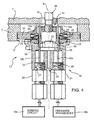
figure 1 is a cross section of a combustion chamber of a gas turbine; -
figure 2 is a perspective view from the top, partially cross-sectional, of a device for fastening thermoinsulating tiles of gas turbine combustion chambers according to an embodiment of the present invention; -
figure 3 is a perspective view from the bottom of the fastening device offigure 2 ; -
figure 4 is a side view, partially cross-sectional along a longitudinal axial plane and with parts removed for greater clarity, of the fastening device offigure 2 ; -
figure 5 is a perspective view from the top, partially cross-sectional, of a device for fastening thermoinsulating tiles of gas turbine combustion chambers according to a different embodiment of the present invention; and -
figure 6 is a side view, partially cross-sectional along a longitudinal axial plane and with parts removed for greater clarity, of the fastening device offigure 5 . - The invention will now be described with special reference to the fastening of thermoinsulating tiles to the inner wall of the casing of a toroidal combustion chamber of a gas turbine. However, the invention may also find advantageous application in different combustion chambers, for example silo combustion chambers.
- With reference to
figure 1 , acombustion chamber 1 of a gas turbine (not shown in its entirety) comprises atoroidal casing 2 extending around an axis A and having a radially outerfirst shell 3, defined by a ring-shaped wall, and a radially inner second shell 4, defined by a wall having substantially frustoconical shape. Thecasing 2 defines a combustion volume V, which extends between thefirst shell 3 and the second shell 4. Thecombustion chamber 1 is provided with thermoinsulating coating, which internally covers thefirst shell 3 and the second shell 4 and comprises a plurality of thermoinsulating tiles. In an embodiment, thethermoinsulating tiles 7 are arranged in adjacent rows along circumferences around the axis A of thecombustion chamber 1. - The
thermoinsulating tiles 7 of at least some rows are fastened to thecasing 2 of thecombustion chamber 1 by fasteningdevices 10 throughrespective housings 17 provided in thefirst shell 3 and in the second shell 4. - With reference to
figures 2 to 4 , in an embodiment of the invention, thefastening device 10 comprises a supportingbody 12, a bushing 13 andcoupling members 14. Furthermore, thefastening device 10 supports atemperature sensor 15 and apressure sensor 16. - The supporting
body 12 is configured to be coupled to ahousing 17 on a face of thecasing 2 that is on the outside relative to the combustion volume V. The supportingbody 12 also has alocking seat 18 and an access opening 20 to receive an end of the bushing 13. Thehousing 17 is defined by a through opening, for example a circular one, in the wall of thecasing 2. - The supporting
body 12 comprises a firstannular element 21, a secondannular element 22 and alid 23. - The first
annular element 21 has an edge that radially projects outward to be coupled in abutment with a corresponding margin of thehousing 17 in thecasing 2. The secondannular element 22 defines a side of thelocking seat 18 opposite to thelid 23. Furthermore, theaccess opening 20 is obtained in the secondannular element 22 and is aligned with a central opening of the firstannular element 21, so as to allow thebushing 13 to be introduced into thelocking seat 18. In other words, thebushing 13 is inserted into thelocking seat 18 through the firstannular element 21 and the secondannular element 22. A pack of Bellevillewashers 25 is arranged between the firstannular element 21 and the secondannular element 22 and allows to comply with the effects of the thermal expansion caused by the high temperatures of thecombustion chamber 1 in use. - The
lid 23 is opposite to the access opening 20, is cup-shaped and defines thelocking seat 18 on one side. Thelid 23 is removably fastened to the firstannular element 21 through screws and it has a first throughsensor seat 27 and a second throughsensor seat 28 to fasten thetemperature sensor 15, by aconnector 30, and thepressure sensor 16, by aconnector 31, respectively. The first throughsensor seat 27 and the second throughsensor seat 28 are provided in a bottom wall of thelid 23 and communicate with thelocking seat 18. - A
central opening 32 of thelid 23, communicating with thelocking seat 18 as well, allows cooling air to flow into the supportingbody 12. - The
bushing 13 is internally threaded and is removably coupled to the supportingbody 12. In an embodiment, the coupling between the bushing 13 and the supportingbody 12 is a bayonet coupling. More in detail, thebushing 13 extends along an axis B, has a substantially cylindrical shape and is provided, at one end, withlocking fins 33 extending radially relative to the axis B. Thebushing 13 can be inserted into thelocking seat 18 through the access opening 20 from the inside of thecasing 2 through thehousing 17 and is angularly movable in thelocking seat 18 between an insertion position, in which thelocking fins 33 are aligned with the access opening 20 and thebushing 13 is axially movable, and a locking position, in which thelocking fins 33 are held in a blind portion of thelocking seat 18. The blind portion of thelocking seat 18 communicates with the access opening 20 and is configured to receive and axially hold thelocking fins 33. - In an embodiment, the
bushing 13 is axially hollow and enables the passage of cooling air. - The
coupling members 14 are coupled to respectivethermoinsulating tiles 7 and, in a non-limiting embodiment, comprise a cup-shaped body 35, for example a substantially cylindrical one, and an axiallyhollow screw 36. The cup-shaped body 35 is housed in a throughseat 37 in one of thethermoinsulating tiles 7 and is provided with aplate 38 for locking against an inner face of thethermoinsulating tile 7 delimiting a portion of the combustion volume V. - The
screw 36 is arranged through a bottom wall of the cup-shaped body 35 and is coupled to an end of the bushing 13 opposite to thelid 23. In particular, thescrew 36 is coupled to thebushing 13 so that, when the bushing is in the locking position in thelocking seat 18, screwing thescrew 36 tends to tighten the secondannular element 22 against the firstannular element 21 and both of them in a clamping manner on the wall of thecasing 2. - As already mentioned above, the
temperature sensor 15 and thepressure sensor 16 are fastened to thefirst sensor seat 27, by theconnector 30, and to thesecond sensor seat 28, by theconnector 31, respectively. The first throughsensor seat 27 and the second throughsensor seat 28 are provided in a bottom wall of thelid 23 and communicate with thelocking seat 18. - The
temperature sensor 15, in an embodiment, is a thermocouple and comprises ajunction 15a and anelectrical connecting line 15b for connecting to asensing circuit 15c, which is schematically shown infigure 4 . - The
pressure sensor 16 comprises apressure inlet 16a and afluidic connecting line 16b for connecting to apressure transducer 16c, which is schematically shown infigure 4 . - The
electrical connecting line 15b and the fluidic connectingline 16b extend through thelid 23 in thefirst sensor seat 27 and in thesecond sensor seat 28, respectively, and through thelocking seat 18. Then, theelectrical connecting line 15b and the fluidic connectingline 16b run adjacent to thebushing 13, through the portions of the access opening 20 that remain free when thebushing 13 is in the locking position. - The sensing members of the
temperature sensor 15 and of thepressure sensor 16, defined by thejunction 15a and by thepressure inlet 16a, respectively, are arranged at ends of theelectrical connecting line 15b and of the fluidic connectingline 16b, close to thethermoinsulating tile 7. - The
fastening device 10 allows quantity detecting sensors to be easily arranged inside thecasing 2 of thecombustion chamber 1, without the need to modify the structure of thecasing 2 by making holes for the sensors. Furthermore, several points are available to install the sensors. As a matter of fact, it is possible to choose the most convenient locations for positioning the sensors, taking into account also easy access for operators, or, alternatively, banks of sensors may be installed to get a series of measures from which, for example, information concerning the symmetry of combustion and, anyway, more accurate data may be obtained. - The sensors may be installed permanently or, if it is preferable based on the circumstances, only temporarily, in order to carry out the measurements. The sensors may be easily be removed by extracting the
connectors seats sensors - A different embodiment of the invention is shown in
figures 5 and6 , where a device for fastening thermoinsulating tiles of gas turbine combustion chambers is indicated withnumber 110. - The
fastening device 110 comprises a supportingbody 112, abushing 113 andcoupling members 114. Thebushing 113 and thecoupling members 114 are substantially like the ones already described with reference tofigures 2-4 . - In particular, the
bushing 113 is removably inserted in a lockingseat 118 in the supportingbody 112 through anaccess opening 120, is internally threaded and axially hollow and has an end that projects in a direction opposite to the supportingbody 112. - The
coupling members 114 are coupled torespective thermoinsulating tiles 7 and, in a non-limiting embodiment, they comprise a substantially cylindrical cup-shapedbody 135 and an axiallyhollow screw 136. The cup-shapedbody 135 is housed in the throughseat 37 of one of thethermoinsulating tiles 7 and is provided with aplate 138 for locking it against a an inner face of thethermoinsulating tile 7 delimiting a portion of the combustion volume V. - The
screw 136 is arranged through a bottom wall of the cup-shapedbody 135 and is coupled to an end of thebushing 113 projecting from theaccess opening 120. - The supporting
body 112 comprises a firstannular element 121 and a secondannular element 122, which are substantially like the firstannular element 21 and the secondannular element 22 described above, and alid 123. - The
lid 123 is cup-shaped and delimits the lockingseat 118 on one side. Thelid 123 is removably fastened to the firstannular element 121 and has asensor seat 127 for fastening asensor 115 by aconnector 130. Thesensor seat 127 is provided in a bottom wall of thelid 123 and communicates with the lockingseat 118. - An
opening 132 diametrically crosses thelid 123. Theopening 132 communicates with the lockingseat 118 and allows cooling air to flow into the supportingbody 112. - The
sensor 115, for example a temperature or pressure sensor, is coupled to thesensor seat 127 by theconnector 130 and has asensing member 115a and a connectingline 115b. Thesensing member 115a (e.g. a junction of a thermocouple or a pressure inlet, depending on the type of sensor used) is arranged at one end of the connectingline 115b (e.g. an electrical connecting line or a fluidic connecting line). In an embodiment, the connectingline 115b extends through thesensor seat 127 and a portion of the lockingseat 118 and, furthermore, through thebushing 113 and thescrew 136, which are aligned with thesensor seat 127. Therefore, thesensing member 115a directly faces the combustion volume V of the combustion chamber, without the interposition of thethermoinsulating tile 7. - Also in this case, the
sensor 115 may be installed in a temporary or permanent manner, depending on the needs. In case of a temporary installation, thelid 123 may be removed and replaced with a lid without sensors. - Furthermore, in a combustion chamber, it is possible to use fastening devices equipped with different sensors. For example, part of the fastening devices may comprise temperature sensors and part of the fastening devices may comprise pressure sensors.
- Finally, it is clear that the fastening device described above may be subjected to changes and variations, without for this reason going beyond the scope of protection of the present invention, as set forth in the appended claims.
- In particular, the coupling members do not necessarily require to have the shape described above, with a cylindrical cup-shaped body provided with a plate and coupled to a respective thermoinsulating tile in the middle. On the contrary, coupling devices (and respective coupling members) may be used, which have any possible configuration, provided that they are suited to hold respective thermoinsulating tiles on the casing of the combustion chamber, of course.
- Any kind of sensor capable of detecting operating quantities of the combustion chamber may be used; temperature sensors and pressure sensors of the type described above are not the only possible solution. As already mentioned above, furthermore, in the same combustion chamber different fastening devices may be used, which are equipped with respective types of sensors that are different from one another.
Claims (16)
- Fastening device for thermoinsulating tiles of gas turbine combustion chambers, comprising:a supporting body (12; 112), provided with a lid (23; 123) and configured to be coupled to a housing (17) of a wall of a combustion chamber (1) of a gas turbine;coupling members (14; 114), connected to the supporting body (12; 112) at an end thereof opposite to the lid (23; 123) and configured to be coupled to thermoinsulating tiles (7) of the combustion chamber (1) through the wall;at least a sensor (15, 16; 115) connected to the lid (23; 123) and having a connecting line (15b, 16b; 115b), that extends through the supporting body (12; 112), and a sensing member (15a, 16a; 115a) at one end of the connecting line (15b, 16b; 115b).
- The fastening device according to claim 1, wherein:the supporting body (12; 112) has a locking seat (18; 118) and an access opening (20; 120) for accessing the locking seat (18; 118);the lid (23; 123) is opposite to the access opening (20; 120) and defines the locking seat (18; 118) on one side;a threaded bushing (13; 113) is removably inserted in the locking seat (18; 118) through the access opening (20; 120); andthe coupling members (14; 114) are connected to the bushing (13; 113) by a screw (36; 136).
- The fastening device according to claim 2, wherein the at least a connecting line (15b, 16b; 115b) extends through the lid (23; 123) and the locking seat (18; 118) of the bushing (13; 113).
- The fastening device according to claim 2 or 3, comprising a first sensor (15) and a second sensor (16) having a first connecting line (15b) and a second connecting line (16b), respectively, wherein:the lid (23) comprises a through first sensor seat (27) and a through second sensor seat (28), provided in a bottom wall and communicating with the locking seat (18);the first sensor (15) and the second sensor (16) have a first connector (30) coupled to the first sensor seat (27) and a second connector (31) coupled to the second sensor seat (28), respectively; andthe first connecting line (15b) and the second connecting line (16b) extend through the first sensor seat (27) and the second sensor seat (28), respectively, and run adjacent to the bushing (13).
- The fastening device according to claim 4, wherein the first connecting line (15b) and the second connecting line (16b) extend through the access opening (20).
- The fastening device according to claim 2 or 3, the lid (123) comprises a through sensor seat (127), centrally provided in a bottom wall and communicating with the locking seat (118);
the sensor (115) has a connector (130) coupled to the sensor seat (127); and
the connecting line (115b) extends through the sensor seat (127). - The fastening device according to claim 6, wherein the screw (136) is axially hollow and is aligned with the sensor seat (127) and the connecting line (115b) extends through the screw (136).
- The fastening device according to any one of claims 2 to 7, wherein:the supporting body (12; 112) comprises a first annular element (21; 121) and a second annular element (22; 122), that defines one side of the locking seat (18; 118) opposite to the lid (23; 123);the access opening (20; 120) is provided in the second annular element (22; 122); andthe bushing (13; 113) is inserted through the first annular element (21; 121) and the second annular element (22; 122).
- The fastening device according to claim 8, wherein the first annular element (21; 121) projects radially outward to be placed in abutment with a margin of the housing (17) in the wall (2) of the combustion chamber (1), so that, when the coupling members (14; 114) are coupled to the thermoinsulating tile (7), screwing the screw (36; 136) tend to tighten the second annular element (22; 122) against the first annular element (21; 121).
- The fastening device according to claim 8 or 9, comprising a pack of Belleville washers (25) between the first annular element (21; 121) and the second annular element (22; 122).
- The fastening device according to any one of claims 8 to 10, wherein the lid (23; 123) is removably fastened to the first annular element (21; 121).
- The fastening device according to any one of claims 2 to 11, wherein:the bushing (13) is provided with radial locking fins (33) ;the locking seat (18) has a blind portion communicating with the access opening (20) and adapted to receive and axially hold the radial locking fins (33); andthe bushing (13) is angularly movable in the locking seat (18) between an insertion position, in which the radial locking fins (33) are aligned to the access opening (20) and the bushing (13) is axially movable, and a locking position, in which the radial locking fins (33) are held in the blind portion of the locking seat (18).
- The fastening device according to any one of the foregoing claims, wherein the sensor (15) is a temperature sensor, the sensing member (15a) comprises a thermocouple and the connecting line (15b) is an electrical connecting line.
- The fastening device according to any one of the foregoing claims, wherein the sensor (15, 16; 115) is a pressure sensor, the sensing member (16a) comprises a pressure inlet and the connecting line (16b) is a fluidic connecting line.
- Combustion chamber of a gas turbine, comprising a casing (2) and a plurality of thermoinsulating tiles (7) arranged on an internal face of the casing (2); wherein the thermoinsulating tiles (7) are fastened to the casing (2) by at least one fastening device (10; 110) according to any one of the foregoing claims.
- Combustion chamber according to claim 15, wherein the supporting body (12; 112) is fastened to and external face of the casing (2), the lid (23; 123) is outside the casing (2) and the bushing (13; 113) is insertable and extractable from inside the casing (2) through a hole.
Applications Claiming Priority (1)
| Application Number | Priority Date | Filing Date | Title |
|---|---|---|---|
| ITMI20150015 | 2015-01-12 |
Publications (2)
| Publication Number | Publication Date |
|---|---|
| EP3043113A1 true EP3043113A1 (en) | 2016-07-13 |
| EP3043113B1 EP3043113B1 (en) | 2018-05-23 |
Family
ID=52633402
Family Applications (1)
| Application Number | Title | Priority Date | Filing Date |
|---|---|---|---|
| EP16150819.7A Active EP3043113B1 (en) | 2015-01-12 | 2016-01-11 | Fastening device for thermoinsulating tile of gas turbine combustion chamber |
Country Status (2)
| Country | Link |
|---|---|
| EP (1) | EP3043113B1 (en) |
| CN (1) | CN105783033B (en) |
Families Citing this family (1)
| Publication number | Priority date | Publication date | Assignee | Title |
|---|---|---|---|---|
| CN115493161A (en) * | 2022-11-15 | 2022-12-20 | 中国航发沈阳发动机研究所 | Gas turbine afterburner pressure pulsation sensor mounting structure |
Citations (3)
| Publication number | Priority date | Publication date | Assignee | Title |
|---|---|---|---|---|
| US4300774A (en) * | 1980-04-28 | 1981-11-17 | General Electric Company | Removable sealing plug for spaced apart wall structure |
| US20030123953A1 (en) * | 2001-09-29 | 2003-07-03 | Razzell Anthony G. | Fastener |
| EP2738470A1 (en) * | 2012-11-28 | 2014-06-04 | Rolls-Royce Deutschland Ltd & Co KG | Shingle attachment assembly of a gas turbine combustion chamber |
Family Cites Families (5)
| Publication number | Priority date | Publication date | Assignee | Title |
|---|---|---|---|---|
| US6951109B2 (en) * | 2004-01-06 | 2005-10-04 | General Electric Company | Apparatus and methods for minimizing and/or eliminating dilution air leakage in a combustion liner assembly |
| EP2236928A1 (en) * | 2009-03-17 | 2010-10-06 | Siemens Aktiengesellschaft | Heat shield element |
| US8647037B2 (en) * | 2012-05-01 | 2014-02-11 | General Electric Company | System and method for assembling an end cover of a combustor |
| US9267378B2 (en) * | 2012-06-27 | 2016-02-23 | General Electric Company | Turbomachine monitoring system and method |
| WO2014179328A1 (en) * | 2013-04-29 | 2014-11-06 | United Technologies Corporation | Joint for sealing a gap between casing segments of an industrial gas turbine engine combustor |
-
2016
- 2016-01-11 EP EP16150819.7A patent/EP3043113B1/en active Active
- 2016-01-12 CN CN201610097239.4A patent/CN105783033B/en active Active
Patent Citations (3)
| Publication number | Priority date | Publication date | Assignee | Title |
|---|---|---|---|---|
| US4300774A (en) * | 1980-04-28 | 1981-11-17 | General Electric Company | Removable sealing plug for spaced apart wall structure |
| US20030123953A1 (en) * | 2001-09-29 | 2003-07-03 | Razzell Anthony G. | Fastener |
| EP2738470A1 (en) * | 2012-11-28 | 2014-06-04 | Rolls-Royce Deutschland Ltd & Co KG | Shingle attachment assembly of a gas turbine combustion chamber |
Also Published As
| Publication number | Publication date |
|---|---|
| EP3043113B1 (en) | 2018-05-23 |
| CN105783033A (en) | 2016-07-20 |
| CN105783033B (en) | 2019-09-17 |
Similar Documents
| Publication | Publication Date | Title |
|---|---|---|
| JP6188050B2 (en) | thermocouple | |
| JP6240661B2 (en) | Fluid control device and thermal sensor installation structure on fluid control device | |
| EP2676065B1 (en) | Acoustic transducer assembly for a pressure vessel | |
| US8337081B1 (en) | Sensor assembly for mounting a temperature sensor to a tank | |
| EP2564034B1 (en) | Bore-scope sealing apparatus and plug therefor | |
| KR102109330B1 (en) | Heating Pipe Module | |
| BR112016000429B1 (en) | method for mounting a differential pressure sensor, and, differential pressure sensor assembly | |
| EP3043113B1 (en) | Fastening device for thermoinsulating tile of gas turbine combustion chamber | |
| KR101115575B1 (en) | Device of measuring the temperature and pressure probe | |
| US10960329B2 (en) | Sensor system and implementation of the same | |
| CN103649614B (en) | Detection probe erecting device, the housing including it and machine and method for maintaining thereof | |
| US10731895B2 (en) | Mounting adaptor for mounting a sensor assembly to a water heater tank | |
| JP2009162590A (en) | Pressure monitoring device | |
| US20130170521A1 (en) | Detector assembly | |
| RU2467295C1 (en) | Device to diagnose condition of flange protective cartridge of thermoelement | |
| JP5992944B2 (en) | Combustion equipment | |
| IT201800008109A1 (en) | IMPROVED THERMOSTAT GROUP | |
| CN210664584U (en) | Temperature and pressure sensor | |
| KR200361034Y1 (en) | Temperature measurement device used thermo couple | |
| CN106437930B (en) | Engine oil heat exchange system for engine and vehicle with same | |
| EP4119910B1 (en) | Protective tube, temperature measurement arrangements and methods for temperature measurements in a process vessel | |
| CN108942084A (en) | The accuracy control method of magnitude of interference in adopting conical surface interference assembling process | |
| KR20190013443A (en) | The equipment for condition monitoring of fluid | |
| US20080127754A1 (en) | Thin-film detecting device | |
| KR100785833B1 (en) | Cryogenic Temperature Measurement System for Expansion Fitting Technology and Measurement Method Using Them |
Legal Events
| Date | Code | Title | Description |
|---|---|---|---|
| PUAI | Public reference made under article 153(3) epc to a published international application that has entered the european phase |
Free format text: ORIGINAL CODE: 0009012 |
|
| AK | Designated contracting states |
Kind code of ref document: A1 Designated state(s): AL AT BE BG CH CY CZ DE DK EE ES FI FR GB GR HR HU IE IS IT LI LT LU LV MC MK MT NL NO PL PT RO RS SE SI SK SM TR |
|
| AX | Request for extension of the european patent |
Extension state: BA ME |
|
| STAA | Information on the status of an ep patent application or granted ep patent |
Free format text: STATUS: REQUEST FOR EXAMINATION WAS MADE |
|
| 17P | Request for examination filed |
Effective date: 20170113 |
|
| RBV | Designated contracting states (corrected) |
Designated state(s): AL AT BE BG CH CY CZ DE DK EE ES FI FR GB GR HR HU IE IS IT LI LT LU LV MC MK MT NL NO PL PT RO RS SE SI SK SM TR |
|
| GRAP | Despatch of communication of intention to grant a patent |
Free format text: ORIGINAL CODE: EPIDOSNIGR1 |
|
| STAA | Information on the status of an ep patent application or granted ep patent |
Free format text: STATUS: GRANT OF PATENT IS INTENDED |
|
| RIC1 | Information provided on ipc code assigned before grant |
Ipc: F23M 5/04 20060101AFI20171116BHEP Ipc: F23R 3/00 20060101ALI20171116BHEP |
|
| INTG | Intention to grant announced |
Effective date: 20171208 |
|
| GRAS | Grant fee paid |
Free format text: ORIGINAL CODE: EPIDOSNIGR3 |
|
| GRAA | (expected) grant |
Free format text: ORIGINAL CODE: 0009210 |
|
| STAA | Information on the status of an ep patent application or granted ep patent |
Free format text: STATUS: THE PATENT HAS BEEN GRANTED |
|
| AK | Designated contracting states |
Kind code of ref document: B1 Designated state(s): AL AT BE BG CH CY CZ DE DK EE ES FI FR GB GR HR HU IE IS IT LI LT LU LV MC MK MT NL NO PL PT RO RS SE SI SK SM TR |
|
| REG | Reference to a national code |
Ref country code: GB Ref legal event code: FG4D |
|
| REG | Reference to a national code |
Ref country code: CH Ref legal event code: EP |
|
| REG | Reference to a national code |
Ref country code: IE Ref legal event code: FG4D |
|
| REG | Reference to a national code |
Ref country code: AT Ref legal event code: REF Ref document number: 1001817 Country of ref document: AT Kind code of ref document: T Effective date: 20180615 |
|
| REG | Reference to a national code |
Ref country code: DE Ref legal event code: R096 Ref document number: 602016003132 Country of ref document: DE |
|
| RAP2 | Party data changed (patent owner data changed or rights of a patent transferred) |
Owner name: ANSALDO ENERGIA S.P.A. |
|
| REG | Reference to a national code |
Ref country code: NL Ref legal event code: MP Effective date: 20180523 |
|
| REG | Reference to a national code |
Ref country code: LT Ref legal event code: MG4D |
|
| PG25 | Lapsed in a contracting state [announced via postgrant information from national office to epo] |
Ref country code: BG Free format text: LAPSE BECAUSE OF FAILURE TO SUBMIT A TRANSLATION OF THE DESCRIPTION OR TO PAY THE FEE WITHIN THE PRESCRIBED TIME-LIMIT Effective date: 20180823 Ref country code: FI Free format text: LAPSE BECAUSE OF FAILURE TO SUBMIT A TRANSLATION OF THE DESCRIPTION OR TO PAY THE FEE WITHIN THE PRESCRIBED TIME-LIMIT Effective date: 20180523 Ref country code: SE Free format text: LAPSE BECAUSE OF FAILURE TO SUBMIT A TRANSLATION OF THE DESCRIPTION OR TO PAY THE FEE WITHIN THE PRESCRIBED TIME-LIMIT Effective date: 20180523 Ref country code: LT Free format text: LAPSE BECAUSE OF FAILURE TO SUBMIT A TRANSLATION OF THE DESCRIPTION OR TO PAY THE FEE WITHIN THE PRESCRIBED TIME-LIMIT Effective date: 20180523 Ref country code: ES Free format text: LAPSE BECAUSE OF FAILURE TO SUBMIT A TRANSLATION OF THE DESCRIPTION OR TO PAY THE FEE WITHIN THE PRESCRIBED TIME-LIMIT Effective date: 20180523 Ref country code: NO Free format text: LAPSE BECAUSE OF FAILURE TO SUBMIT A TRANSLATION OF THE DESCRIPTION OR TO PAY THE FEE WITHIN THE PRESCRIBED TIME-LIMIT Effective date: 20180823 |
|
| PG25 | Lapsed in a contracting state [announced via postgrant information from national office to epo] |
Ref country code: NL Free format text: LAPSE BECAUSE OF FAILURE TO SUBMIT A TRANSLATION OF THE DESCRIPTION OR TO PAY THE FEE WITHIN THE PRESCRIBED TIME-LIMIT Effective date: 20180523 Ref country code: HR Free format text: LAPSE BECAUSE OF FAILURE TO SUBMIT A TRANSLATION OF THE DESCRIPTION OR TO PAY THE FEE WITHIN THE PRESCRIBED TIME-LIMIT Effective date: 20180523 Ref country code: RS Free format text: LAPSE BECAUSE OF FAILURE TO SUBMIT A TRANSLATION OF THE DESCRIPTION OR TO PAY THE FEE WITHIN THE PRESCRIBED TIME-LIMIT Effective date: 20180523 Ref country code: GR Free format text: LAPSE BECAUSE OF FAILURE TO SUBMIT A TRANSLATION OF THE DESCRIPTION OR TO PAY THE FEE WITHIN THE PRESCRIBED TIME-LIMIT Effective date: 20180824 Ref country code: LV Free format text: LAPSE BECAUSE OF FAILURE TO SUBMIT A TRANSLATION OF THE DESCRIPTION OR TO PAY THE FEE WITHIN THE PRESCRIBED TIME-LIMIT Effective date: 20180523 |
|
| REG | Reference to a national code |
Ref country code: AT Ref legal event code: MK05 Ref document number: 1001817 Country of ref document: AT Kind code of ref document: T Effective date: 20180523 |
|
| PG25 | Lapsed in a contracting state [announced via postgrant information from national office to epo] |
Ref country code: SK Free format text: LAPSE BECAUSE OF FAILURE TO SUBMIT A TRANSLATION OF THE DESCRIPTION OR TO PAY THE FEE WITHIN THE PRESCRIBED TIME-LIMIT Effective date: 20180523 Ref country code: RO Free format text: LAPSE BECAUSE OF FAILURE TO SUBMIT A TRANSLATION OF THE DESCRIPTION OR TO PAY THE FEE WITHIN THE PRESCRIBED TIME-LIMIT Effective date: 20180523 Ref country code: CZ Free format text: LAPSE BECAUSE OF FAILURE TO SUBMIT A TRANSLATION OF THE DESCRIPTION OR TO PAY THE FEE WITHIN THE PRESCRIBED TIME-LIMIT Effective date: 20180523 Ref country code: PL Free format text: LAPSE BECAUSE OF FAILURE TO SUBMIT A TRANSLATION OF THE DESCRIPTION OR TO PAY THE FEE WITHIN THE PRESCRIBED TIME-LIMIT Effective date: 20180523 Ref country code: DK Free format text: LAPSE BECAUSE OF FAILURE TO SUBMIT A TRANSLATION OF THE DESCRIPTION OR TO PAY THE FEE WITHIN THE PRESCRIBED TIME-LIMIT Effective date: 20180523 Ref country code: AT Free format text: LAPSE BECAUSE OF FAILURE TO SUBMIT A TRANSLATION OF THE DESCRIPTION OR TO PAY THE FEE WITHIN THE PRESCRIBED TIME-LIMIT Effective date: 20180523 Ref country code: EE Free format text: LAPSE BECAUSE OF FAILURE TO SUBMIT A TRANSLATION OF THE DESCRIPTION OR TO PAY THE FEE WITHIN THE PRESCRIBED TIME-LIMIT Effective date: 20180523 |
|
| REG | Reference to a national code |
Ref country code: DE Ref legal event code: R097 Ref document number: 602016003132 Country of ref document: DE |
|
| PG25 | Lapsed in a contracting state [announced via postgrant information from national office to epo] |
Ref country code: IT Free format text: LAPSE BECAUSE OF FAILURE TO SUBMIT A TRANSLATION OF THE DESCRIPTION OR TO PAY THE FEE WITHIN THE PRESCRIBED TIME-LIMIT Effective date: 20180523 Ref country code: SM Free format text: LAPSE BECAUSE OF FAILURE TO SUBMIT A TRANSLATION OF THE DESCRIPTION OR TO PAY THE FEE WITHIN THE PRESCRIBED TIME-LIMIT Effective date: 20180523 |
|
| PLBE | No opposition filed within time limit |
Free format text: ORIGINAL CODE: 0009261 |
|
| STAA | Information on the status of an ep patent application or granted ep patent |
Free format text: STATUS: NO OPPOSITION FILED WITHIN TIME LIMIT |
|
| 26N | No opposition filed |
Effective date: 20190226 |
|
| PG25 | Lapsed in a contracting state [announced via postgrant information from national office to epo] |
Ref country code: SI Free format text: LAPSE BECAUSE OF FAILURE TO SUBMIT A TRANSLATION OF THE DESCRIPTION OR TO PAY THE FEE WITHIN THE PRESCRIBED TIME-LIMIT Effective date: 20180523 |
|
| PG25 | Lapsed in a contracting state [announced via postgrant information from national office to epo] |
Ref country code: MC Free format text: LAPSE BECAUSE OF FAILURE TO SUBMIT A TRANSLATION OF THE DESCRIPTION OR TO PAY THE FEE WITHIN THE PRESCRIBED TIME-LIMIT Effective date: 20180523 |
|
| REG | Reference to a national code |
Ref country code: CH Ref legal event code: PL |
|
| PG25 | Lapsed in a contracting state [announced via postgrant information from national office to epo] |
Ref country code: LU Free format text: LAPSE BECAUSE OF NON-PAYMENT OF DUE FEES Effective date: 20190111 |
|
| REG | Reference to a national code |
Ref country code: BE Ref legal event code: MM Effective date: 20190131 |
|
| REG | Reference to a national code |
Ref country code: IE Ref legal event code: MM4A |
|
| PG25 | Lapsed in a contracting state [announced via postgrant information from national office to epo] |
Ref country code: FR Free format text: LAPSE BECAUSE OF NON-PAYMENT OF DUE FEES Effective date: 20190131 |
|
| PG25 | Lapsed in a contracting state [announced via postgrant information from national office to epo] |
Ref country code: AL Free format text: LAPSE BECAUSE OF FAILURE TO SUBMIT A TRANSLATION OF THE DESCRIPTION OR TO PAY THE FEE WITHIN THE PRESCRIBED TIME-LIMIT Effective date: 20180523 Ref country code: BE Free format text: LAPSE BECAUSE OF NON-PAYMENT OF DUE FEES Effective date: 20190131 |
|
| PG25 | Lapsed in a contracting state [announced via postgrant information from national office to epo] |
Ref country code: LI Free format text: LAPSE BECAUSE OF NON-PAYMENT OF DUE FEES Effective date: 20190131 Ref country code: CH Free format text: LAPSE BECAUSE OF NON-PAYMENT OF DUE FEES Effective date: 20190131 |
|
| PG25 | Lapsed in a contracting state [announced via postgrant information from national office to epo] |
Ref country code: IE Free format text: LAPSE BECAUSE OF NON-PAYMENT OF DUE FEES Effective date: 20190111 |
|
| PG25 | Lapsed in a contracting state [announced via postgrant information from national office to epo] |
Ref country code: TR Free format text: LAPSE BECAUSE OF FAILURE TO SUBMIT A TRANSLATION OF THE DESCRIPTION OR TO PAY THE FEE WITHIN THE PRESCRIBED TIME-LIMIT Effective date: 20180523 |
|
| PG25 | Lapsed in a contracting state [announced via postgrant information from national office to epo] |
Ref country code: MT Free format text: LAPSE BECAUSE OF NON-PAYMENT OF DUE FEES Effective date: 20190111 Ref country code: PT Free format text: LAPSE BECAUSE OF FAILURE TO SUBMIT A TRANSLATION OF THE DESCRIPTION OR TO PAY THE FEE WITHIN THE PRESCRIBED TIME-LIMIT Effective date: 20180924 |
|
| GBPC | Gb: european patent ceased through non-payment of renewal fee |
Effective date: 20200111 |
|
| PG25 | Lapsed in a contracting state [announced via postgrant information from national office to epo] |
Ref country code: GB Free format text: LAPSE BECAUSE OF NON-PAYMENT OF DUE FEES Effective date: 20200111 |
|
| PG25 | Lapsed in a contracting state [announced via postgrant information from national office to epo] |
Ref country code: CY Free format text: LAPSE BECAUSE OF FAILURE TO SUBMIT A TRANSLATION OF THE DESCRIPTION OR TO PAY THE FEE WITHIN THE PRESCRIBED TIME-LIMIT Effective date: 20180523 |
|
| PG25 | Lapsed in a contracting state [announced via postgrant information from national office to epo] |
Ref country code: IS Free format text: LAPSE BECAUSE OF FAILURE TO SUBMIT A TRANSLATION OF THE DESCRIPTION OR TO PAY THE FEE WITHIN THE PRESCRIBED TIME-LIMIT Effective date: 20180923 |
|
| PG25 | Lapsed in a contracting state [announced via postgrant information from national office to epo] |
Ref country code: HU Free format text: LAPSE BECAUSE OF FAILURE TO SUBMIT A TRANSLATION OF THE DESCRIPTION OR TO PAY THE FEE WITHIN THE PRESCRIBED TIME-LIMIT; INVALID AB INITIO Effective date: 20160111 |
|
| PG25 | Lapsed in a contracting state [announced via postgrant information from national office to epo] |
Ref country code: MK Free format text: LAPSE BECAUSE OF FAILURE TO SUBMIT A TRANSLATION OF THE DESCRIPTION OR TO PAY THE FEE WITHIN THE PRESCRIBED TIME-LIMIT Effective date: 20180523 |
|
| P01 | Opt-out of the competence of the unified patent court (upc) registered |
Effective date: 20240430 |
|
| PGFP | Annual fee paid to national office [announced via postgrant information from national office to epo] |
Ref country code: DE Payment date: 20260120 Year of fee payment: 11 |